CCR Certification: Initial Inflow Design Flood Control System Plan for the. East Ash Pond. at the. F.B. Culley Generating Station.
|
|
|
- Ashlie Janel Phelps
- 6 years ago
- Views:
Transcription
 One Vectren Square Evansville, IN 4772 Submitted by AECOM 94 Amberglen")

1 Submitted to Southern Indiana Gas & Electric Company dba Vectren Power Supply, Inc. (SIGECO) One Vectren Square Evansville, IN 4772 Submitted by AECOM 94 Amberglen Boulevard Austin, Texas October 13, 216 CCR Certification: Initial Inflow Design Flood Control System Plan for the East Ash Pond at the F.B. Culley Generating Station Revision
2 AECOM CCR Certification: Initial Inflow Design Flood Control System Plan for the East Ash Pond at the F.B. Culley Generating Station i Table of Contents Table of Contents Executive Summary... ES-1 1 Introduction Purpose of This Report Brief Description of Impoundment Inflow from Plant Operations and Stormwater Runoff Outlet Structures Hydrologic Analysis Design Storm Rainfall Data Runoff Computations Hydraulic Analyses Process Flows Storage Capacity Discharge Analysis Results Inflow Analysis Outflow Analysis Inflow Design Flood Discharge Conclusions Certification Limitations October 13, 216
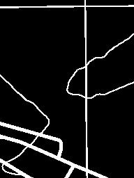
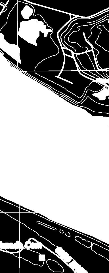
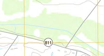
3 AECOM CCR Certification: Initial Inflow Design Flood Control System Plan for the East Ash Pond at the F.B. Culley Generating Station i Table of Contents Tables Table ES-1 Certification Summary Table 1-1 CCR Rule Cross Reference Table Table Summary of Hydrologic and Hydraulic Analysis 1,-Year, 24-Hour Storm Table Summary of Outlet Devices 1,-Year, 24-Hour Storm Appendices Appendix A Figures Figure 1 Location Map Figure 2 Site Map Figure 3 Drainage Area Map Appendix B Hydrologic and Hydraulic Calculations October 13, 216
4 AECOM CCR Certification: Initial Inflow Design Flood Control System Plan for the East Ash Pond at the F.B. Culley Generating Station ES-1 Executive Summary Executive Summary This Coal Combustion Residuals (CCR) Initial Inflow Design Flood Control System Plan (Inflow Flood Control Plan) for the East Ash Pond at the Southern Indiana Gas & Electric Company, dba Vectren Power Supply, Inc. F.B. Culley Generating Station has been prepared in accordance with the requirements specified in the USEPA CCR Rule under 4 Code of Federal Regulations CFR (a). These regulations require that the specified documentation, assessments and plans for an existing CCR surface impoundment be prepared by October 17, 216. This Inflow Flood Control Plan meets the regulatory requirements as summarized in Table ES-1. Table ES-1 Certification Summary Report Section CCR Rule Reference Requirement Summary Requirement Met? Comments Initial Inflow Design Flood Control System Plan (a)(1) Adequately manage flow into the CCR unit during and following the peak discharge of the inflow design flood Yes CCR unit has the storage capacity to handle the inflow design flood (a)(2) Adequately manage flow from the CCR unit to collect and control the peak discharge resulting from the inflow design flood (a)(3) Required Inflow design flood for Significant Hazard Potential Impoundment Yes Yes The pond has adequate capacity to contain 1,- year 24-hour storm with or without operational outlet pumps. Inflow design flood utilized was the 1,-year event (b) Discharge handled in accordance with Yes CCR unit discharges in accordance with the existing NPDES permit The East Ash Pond is considered to be a significant hazard potential CCR surface impoundment, therefore per (a)(3), the inflow design flood is the 1,-year flood. In accordance with the requirements of (a)(3), an Inflow Flood Control Plan was developed for the East Ash Pond. This was accomplished by evaluating the effects of a 24-hour duration design storm for the 1,-year Inflow Design Flood (IDF) to evaluate the East October 13, 216
5 AECOM CCR Certification: Initial Inflow Design Flood Control System Plan for the East Ash Pond at the F.B. Culley Generating Station ES-2 Executive Summary Ash Pond s ability to collect and control the 1,-year IDF of 1.2 inches, under existing operational and maintenance procedures. Under these conditions there are several interconnected and non-connected pools within the East Ash Pond. These pools are being utilized for treatment and removal of CCR material in the pond. The only outlet from the pond is a pump station, which the interconnected pools are tied to. This outlet does not allow for free flow discharge if the pump station was to malfunction or lose power. To simulate the worst case scenario, the analysis was completed with no pumps running in the East Ash Pond as if there was a malfunction or power outage at the pump station. Therefore, the East Ash Pond would be required to collect and store the 1,-year IDF. The results for the East Ash Pond indicate that the CCR unit has sufficient storage capacity and outlet structures to adequately manage inflows and collect and control outflows during peak discharge conditions created by the 1,-year IDF. October 13, 216
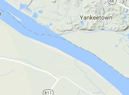
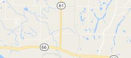
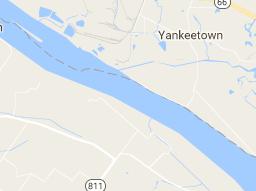
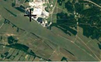
6 AECOM CCR Certification: Initial Inflow Design Flood Control System Plan for the East Ash Pond at the F.B. Culley Generating Station 1-1 Introduction 1 Introduction 1.1 Purpose of This Report The purpose of the Initial Inflow Design Flood Control System Plan (Inflow Flood Control Plan) is to document that the requirements specified in 4 code of Federal Regulations (CFR) have been met to support the certification required under each of the applicable regulatory provisions for the F.B. Culley Generating Station (Culley) East Ash Pond. The East Ash Pond is an existing coal combustion residuals (CCR) surface impoundment as defined by 4 CFR The CCR Rule requires that the, Inflow Flood Control Plan for an existing CCR surface impoundment be prepared by October 17, 216. The East Ash Pond has been evaluated to determine whether the inflow design flood control system requirements are met. The following table summarizes the documentation required within the CCR Rule and the sections that specifically respond to those requirements of this plan. Table 1-1 CCR Rule Cross Reference Table Report Section Title CCR Rule Reference 4.1 Inflow Analysis (a)(1) 4.2 Outflow Analysis (a)(2) 4.3 Inflow Design Flood (a)(3) 4.4 Discharge handled in accordance with (b) Analyses completed for the hydrologic and hydraulic assessments of the East Ash Pond are described in this report. Data and analyses results in the following sections are based on spillway design information shown on design drawings, topographic surveys, information about operational and maintenance procedures provided by Southern Indiana Gas & Electric Company, dba Vectren Power Supply, Inc. (SIGECO), and limited field measurements collected by AECOM. The analysis approach and results of the hydrologic and hydraulic analyses presented in the following sections were used by AECOM to confirm that the East Ash Pond meets the hydrologic and hydraulic capacity requirements of the rules referenced above for CCR surface impoundments. 1.2 Brief Description of Impoundment The Culley station is located in Warrick County, Indiana, southeast of Newburgh, Indiana, and is owned and operated by SIGECO. The station is located along the north bank of the Ohio River and the west bank of the Little Pigeon Creek along the southeast portion of the site. The Culley station consists of two CCR surface impoundments, identified as the West Pond and East Ash Pond. The East Pond is actively receiving CCR materials. The East Ash Pond is located directly east of the station and is approximately 1 acres in size. October 13, 216
7 AECOM CCR Certification: Initial Inflow Design Flood Control System Plan for the East Ash Pond at the F.B. Culley Generating Station 1-2 Introduction The East Ash Pond was commissioned in or around 1971 and operates as an unlined CCR impoundment. Earthen embankments were constructed along the south and east sides of the impoundment. Structural fill used for the original construction of the Culley station in the 195 s borders the impoundment to the west side, and west end of the north side. The east embankment intersects a natural hillside on the east end of the north side of the impoundment. The embankment is approximately 1,2 feet long, 3 feet high, and has 2.4 to 1 (horizontal to vertical) exterior side slopes covered with grassy vegetation. Interior side slopes varied from 2.5 to 1 (horizontal to vertical) to 2 to 1 (horizontal to vertical) for the upper and lower portion of the embankment, respectively. The embankment crest elevation varies from feet 1 to feet and has a crest width of approximately 15 feet. The surface area of the impoundment is approximately 9.8 acres. Within the pond, there are several small pools that are being utilized for treatment and separation of CCR material within the pond as part of an ongoing construction project. The ponding water has a surface area of approximately 2.56 acres and has normal operating level of 387 feet. A site Location Map showing the area surrounding the station is in Figure 1 of Appendix A. Figure 2 in Appendix A presents the F.B. Culley Generating Station Site Map Inflow from Plant Operations and Stormwater Runoff Bottom ash and flue gas desulfurization (FGD) blowdown material were previously sluiced from the plant into the eastern side of the impoundment at a rate of approximately.42 cubic feet per second. The water was discharged from the impoundment via pumping station through a permitted National Pollutant Discharge Elimination System (NPDES) outfall, identified as Internal Outfall 21, at a rate of.42 cfs. Due to operational changes at the station, there is no current inflow into the East Ash Pond from plant operations. In addition to rain that falls directly into the impoundment, there are upstream areas that contribute runoff to the impoundment. The grassy areas to the north drain directly to the East Ash Pond through ditches and culverts. The rest of the site areas, including the plant area, coal pile, and grassy areas to the northwest of the site drain to the inactive West Ash Pond where collected stormwater in the pond is pumped to the West Ash Pond pump station and is discharge to the Ohio River through the permitted outfall. The total drainage area to the East Ash Pond impoundment is approximately 25.8 acres Outlet Structures Water discharges from the impoundment through a pump station located at the west side of the East Ash Pond. The pond pump station consists of two CP 317 LT 3~63 model 5,4 gpm submersible pumps manufactured by Flygt. The 1 pump discharge connects to a manhole on an 84 inch pipe that discharges to an underground discharge tunnel, which collects stormwater and other process water from throughout the Culley station and then discharges to the Ohio River through NPDES permitted Outfall 1. 1 Unless otherwise noted, all elevations in this report are in the NAVD88 datum. October 13, 216
8 AECOM CCR Certification: Initial Inflow Design Flood Control System Plan for the East Ash Pond at the F.B. Culley Generating Station 2-1 Hydrologic Analysis 2 Hydrologic Analysis 2.1 Design Storm The East Ash Pond has been categorized as a Significant hazard potential CCR impoundment, which requires that the inflow design flood is the 1,-year return frequency design storm event. The full analysis for this classification determination is included in the CCR Certification: Initial Hazard Potential Classification for the East Ash Pond at the F.B. Culley Generating Station. 2.2 Rainfall Data The rainfall information used in the analysis was based on the National Oceanic and Atmospheric Administration (NOAA) Atlas 14, Volume 2, Version 3 which provides rainfall data for storm events with average recurrence intervals ranging from 1 to 1, years and durations ranging from 5 minutes to 6 days. The design storm rainfall depth, obtained from the NOAA website, is 1.2 inches for the 24-hour, 1,-year storm. The Indiana Huff, Third Quartile rainfall distribution was used by AECOM and is appropriate to use for storms up to the 1,- year, 24-hour flood at the project site. 2.3 Runoff Computations The drainage areas for the East Ash Pond were estimated using a computer-aided design (CAD) analysis of aerial survey conducted in 211 and topographic ground surveys completed in 215 by Three I Design and a drone topographic survey completed in 216 by Lochmueller Group. The grassy areas to the north drain directly to the East Ash Pond. The total drainage area to the East Ash Pond is approximately 25.8 acres. See Appendix A for the Drainage Area Maps. Runoff was calculated using the SCS Curve Number Method, where curve numbers (CN) were assigned to each subcatchment based on the type of land cover and soil type present. Using the USDA Natural Resources Conservation Service (NRCS) Web Soil Survey, the soil type of the site was selected as hydrologic soil group B. CN values for the land cover were selected from the CN Table available in HydroCAD. This data was obtained from the SCS NRCS Technical Release-55 (TR-55) publication. Ash, Industrial Areas, Water Surface, 5-75% grass cover, and >75% grass covers that are located on site were estimated to have CN values of 88, 88, 98, 69 and 61 respectively. A composite CN was calculated for each subcatchment area by summing the products of each CN multiplied by its percentage of the total area. The time of concentration is commonly defined as the time required for runoff to travel from the most hydrologically distant point to the point of collection. Calculations for the time of concentration for each subwatershed were performed in HydroCAD and are included in Appendix B. Stormwater runoff from the 1,-year event into the impoundment has a peak inflow of cfs and total inflow volume of acre-feet. Refer to Appendix B for HydroCAD results. October 13, 216
9 AECOM CCR Certification: Initial Inflow Design Flood Control System Plan for the East Ash Pond at the F.B. Culley Generating Station 3-1 Hydraulic Analyses 3 Hydraulic Analyses 3.1 Process Flows Process water containing bottom ash is currently pumped from the plant into the East Ash Pond at rate of.42 cubic feet per second or.27 million gallons per day (MGD). 3.2 Storage Capacity The storage volumes for the East Ash Pond were evaluated using a computer-aided design (CAD) analysis to estimate the volume of the pond under the conditions present. A survey was performed on September 29, 216 to verify the available volume within the East Ash Pond after ash removal operations. The volume of storage was calculated by estimating the incremental storage volume present for each 1 foot elevation within the updated topographic surface supplied by SIGECO representatives. The incremental storage volume was then used to calculate a cumulative storage volume and was input into HydroCAD. The volume of storage provided by the interconnected construction pools within the East Ash Pond from normal pool elevation of 387 feet to the top of embankment elevation of feet is approximately 3.37 acre-feet. This volume was determined with the assumption that the pools within the East Ash Pond basin are connected through culverts, allowing storm volumes to be shared by the connected pools. Refer to Appendix B for further storage volumes details. 3.3 Discharge Analysis A hydraulic model was created in HydroCAD 1. to assess the capacity of the pond to store and convey the storm flows. HydroCAD has the capability to evaluate each pond within the network, to respond to variable tailwater, pumping rates, permit flow loops, and reversing flows. HydroCAD routing calculations reevaluate the pond systems discharge capability at each time increment, making the program an efficient and dynamic tool for this evaluation. The analyzed scenario assumes the starting water surface elevation of the interconnected construction pools within the East Ash Pond is 387 feet. For the purposes of this analysis, the East Ash Pond was analyzed as if neither pump within its pump station was operational. This represents a worst case scenario. As such, the East Ash Pond must store the design storm. Therefore, the facility does not cause a discharge of pollutants into waters of the United States that is in violation of the requirements of the NPDES under section 42 of the Clean Water Act. October 13, 216
10 AECOM CCR Certification: Initial Inflow Design Flood Control System Plan for the East Ash Pond at the F.B. Culley Generating Station 4-1 Results 4 Results The hydrologic and hydraulic conditions of the East Ash Pond were modeled with the peak discharge of the 1,-year storm event. Regulatory Citation: 4 CFR (a); The owner or operator of an existing or new CCR surface impoundment or any lateral expansion of a CCR of a CCR surface impoundment must design, construct, operate, and maintain an inflow design flood control system as specified in paragraphs (a)(1) and (2) of this section. 4.1 Inflow Analysis Regulatory Citation: 4 CFR (a); (1) The inflow design flood control system must adequately manage flow into the CCR unit during and following the peak discharge of the inflows design flood specified in paragraph (3). Background and Assessment The East Ash Pond collects runoff from only a small area of the Culley station site and this runoff drains to the pond through sheet flow, overland ditching, and culverts located on the northwest side of the pond. These runoff volumes, in addition to the rainfall falling within the pond itself, produce the total inflow to the East Ash Pond. Using the HydroCAD model, the total inflow was stored within the East Ash Pond to evaluate the resulting peak water surface elevation. Table 4-1 summarizes the maximum water surface elevation of the construction pools within the East Ash Pond prior to and after the inflow design flood. Table Summary of Hydrologic and Hydraulic Analysis 1,-Year, 24-Hour Storm CCR Unit Beginning WSE 1 (feet) Peak WSE (feet) Top of Dam Elevation (feet) Freeboard Above Peak WSE (feet) East Ash Pond Notes: 1 WSE = Water Surface Elevation Conclusion and Recommendation As there is adequate storage within the East Ash Pond to manage the inflow design flood, there is no anticipated overtopping of the East Ash Pond embankment, which meets the requirements in (a)(1). 4.2 Outflow Analysis Regulatory Citation: 4 CFR (a); (2) The inflow design flood control system must adequately manage flow from the CCR unit to collect and control the peak discharge resulting from the inflow design flood specified in paragraph (3) of this section. October 13, 216
11 AECOM CCR Certification: Initial Inflow Design Flood Control System Plan for the East Ash Pond at the F.B. Culley Generating Station 4-2 Results Background and Assessment The East Ash Pond currently collects stormwater from a small area of the site including the grass areas to the north routed through a series of ditches and culverts, as well as any rainfall that falls directly within the perimeter embankments. The rain falling within the pond and the stormwater runoff directly draining to the pond, combine to produce the total inflow to the East Ash Pond. Using the HydroCAD model, the total inflow was stored within the East Ash Pond to estimate the peak water surface elevation during the design storm when the Ohio River is experiencing a 1-year flood. Table 4-2 summarizes the peak flowrates and velocities through each of the outlet devices. Table Summary of Outlet Devices 1,-Year, 24-Hour Storm Invert Elevation (feet) Peak Flowrate Velocity at Peak Flowrate (fps) Outlet Device Type and Size Pump Station - Outlet 2 pump 54 GPM; CP 317 LT 3~ N/A N/A Top of Berm Lowest Elevation Weir Conclusion and Recommendation In the case where the East Ash Pond pump station is not operational, AECOM recommends the Culley station provide pumping capacity equal to the existing lift station pumps by means of providing supplemental pumps or bringing the existing lift station pumps online within 48-hours. As the East Ash Pond can store the design storm from the plant without utilizing its pump station and without the peak water surface elevation overtopping the East Ash Pond embankment, the pond meets the requirements in (a)(2). 4.3 Inflow Design Flood Regulatory Citation: 4 CFR (a); (3) The inflow design flood is: o (i) For a high hazard potential CCR surface impoundment, as determined under (a)(2), the probable maximum flood; o (ii) For a significant hazard potential CCR surface impoundment, as determined under (a)(2), the 1,-year flood; o (iii) For a low hazard potential CCR surface impoundment, as determined under (a)(2), the 1-year flood; or October 13, 216
12 AECOM CCR Certification: Initial Inflow Design Flood Control System Plan for the East Ash Pond at the F.B. Culley Generating Station 4-3 Results o (iv) For an incised CCR surface impoundment, the 25-year flood. Background and Assessment The calculations for the inflow design flood are based on the hazard potential given to the impoundment. The different classifications of the impoundment hazard potential are high, significant, and low. Conclusion and Recommendation As the impoundment was given a significant hazard potential, the 1, year design storm was utilized in the analysis, which meets the requirements in (a)(3). 4.4 Discharge Regulatory Citation: 4 CFR (b); Discharge from the CCR unit must be handled in accordance with the surface water requirements under: Background and Assessment The East Ash Pond was modeled without a working pump station to simulate a worst case scenario. As such, there is no discharge from the pond in this model scenario. However, during normal operating conditions the discharge from the East Ash Pond pump station is conveyed through a 1 pipe that connects to a manhole on an 84 pipe and discharges to an underground discharge tunnel, which also collects discharge water from the cooling water system and various other clean discharge water sources located throughout the power plant. The underground discharge tunnel runs by the basement of Unit 2 within the power plant and discharges directly to the Ohio River through NPDES Permitting Outfall 1. The Ohio River was modeled at the FEMA 1 year flood elevation of The discharge must meet the requirements of the NDPES under section 42 of the Clean Water Act to meet the CCR rule. Conclusion and Recommendation No modifications are necessary or recommended to this unit for compliance with the CCR Rule. Runoff discharges from the site through a permitted NPDES outfall. As per the current NPDES permit, all discharged water is tested for pollutants to meet the minimum regulatory requirements of the permit, and thereby meets the requirements in (b). October 13, 216
13 AECOM CCR Certification: Initial Inflow Design Flood Control System Plan for the East Ash Pond at the F.B. Culley Generating Station 5-1 Conclusions 5 Conclusions The Inflow Flood Control Plan of the East Ash Pond adequately manages flow into the CCR unit during and following the peak discharge of the 1,-year frequency storm event inflow design flood. The inflow design flood control system of the East Ash Pond adequately manages flow from the CCR unit to collect and control the peak discharge resulting from the 1,-year frequency storm event inflow design flood. Therefore, the East Ash Pond meets the requirements for certification. In the case where the East Ash Pond pump station is not operational, AECOM recommended that the Culley Generating Station provide pumping capacity equal to the existing lift station pumps by means of providing supplemental pumps or bringing the existing lift station pumps online within 48-hours. The contents of this report, specifically Sections 1 through 4, represent the Initial Inflow Design Flood Control System Plan for this site. October 13, 216


14
15 AECOM CCR Certification: Initial Inflow Design Flood Control System Plan for the East Ash Pond at the F.B. Culley Generating Station 7-1 Limitations 7 Limitations Background information, design basis, and other data which AECOM has used in preparing this report have been furnished to AECOM by SIGECO. AECOM has relied on this information as furnished, and is not responsible for the accuracy of this information. Our recommendations are based on available information from previous and current investigations. These recommendations may be updated as future investigations are performed. The conclusions presented in this report are intended only for the purpose, site location, and project indicated. The recommendations presented in this report should not be used for other projects or purposes. Conclusions or recommendations made from these data by others are their responsibility. The conclusions and recommendations are based on AECOM s understanding of current plant operations, maintenance, stormwater handling, and ash handling procedures at the station, as provided by SIGECO. Changes in any of these operations or procedures may invalidate the findings in this report until AECOM has had the opportunity to review the findings, and revise the report if necessary. This hydrologic and hydraulic analysis was performed in accordance with the standard of care commonly used as state-of-practice in our profession. Specifically, our services have been performed in accordance with accepted principles and practices of the engineering profession. The conclusions presented in this report are professional opinions based on the indicated project criteria and data available at the time this report was prepared. Our services were provided in a manner consistent with the level of care and skill ordinarily exercised by other professional consultants under similar circumstances. No other representation is intended. While the CCR unit adequately manages the inflow design flood, SIGECO must perform routine maintenance on the CCR unit to continually manage flood events without failure. The pump station should be cleared of debris that could block or damage the device. The interconnected construction pools within the East Ash Pond should maintain a water surface elevation at or below 387 feet. Pipes, intake structures, and pumps should be monitored and repaired if deterioration or deformation occurs. All grass lined slopes should be examined for erosion and repaired if damaged. Rip rap lined channels should be inspected for stones that have shifted or bare spots that have formed. Replace rip rap as needed. Additionally, in the case where the East Ash Pond pump station is not working, SIGECO shall provide pumping capacity equal to the existing lift station pumps by means of providing supplemental pumps or bringing the existing lift station pumps online within 48-hours. October 13, 216
16 AECOM CCR Certification: Initial Inflow Design Flood Control System Plan for the East Ash Pond at the F.B. Culley Generating Station Appendix A Figures Figure 1 Location Map Figure 2 Site Map Figure 3 Drainage Area Map October 13, 216


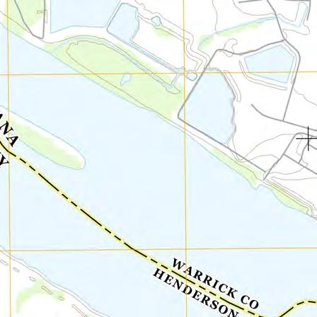


17 94 Amberglen Boulevard Austin, TX (phone) (fax) SOUTHERN INDIANA GAS AND ELECTRIC COMPANY dba VECTREN POWER SUPPLY, INC. One Vectren Square Evansville, IN (phone) F.B. CULLEY GENERATING STATION NEWBURGH, IN CCR CERTIFICATION EAST ASH POND ISSUED FOR CERTIFICATION ISSUED FOR BIDDING DATE BY ISSUED FOR CONSTRUCTION DATE BY REVISIONS NO. DESCRIPTION DATE F.B. CULLEY GENERATING STATION CULLEY EAST ASH POND AECOM PROJECT NO: DRAWN BY: DESIGNED BY: CHECKED BY: DATE CREATED: PLOT DATE: SCALE: ACAD VER: SHEET TITLE MJC MJC TLE 8/18/216 4/22/216 AS SHOWN 214 LOCATION MAP SCALE IN FEET
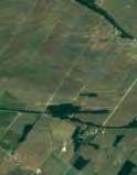
18 94 Amberglen Boulevard Austin, TX (phone) (fax) SOUTHERN INDIANA GAS AND ELECTRIC COMPANY dba VECTREN POWER SUPPLY, INC. One Vectren Square Evansville, IN (phone) F.B. CULLEY GENERATING STATION NEWBURGH, IN CCR CERTIFICATION EAST ASH POND CULLEY WEST ASH POND ISSUED FOR CERTIFICATION ISSUED FOR BIDDING DATE BY ISSUED FOR CONSTRUCTION DATE BY COAL PILE REVISIONS NO. DESCRIPTION DATE CULLEY GENERATING STATION OHIO RIVER CULLEY EAST ASH POND LITTLE PIGEON CREEK AECOM PROJECT NO: DRAWN BY: DESIGNED BY: CHECKED BY: DATE CREATED: PLOT DATE: SCALE: ACAD VER: SHEET TITLE MJC MJC TLE 8/18/216 4/22/216 AS SHOWN SCALE IN FEET SITE MAP
 SUBC")
19 94 Amberglen Boulevard Austin, TX (phone) (fax) SUBCATCHMENT 4 AREA = 11.1 ACRES SUBCATCHMENT 6 AREA = 3.8 ACRES SOUTHERN INDIANA GAS AND ELECTRIC COMPANY dba VECTREN POWER SUPPLY, INC. One Vectren Square Evansville, IN (phone) SUBCATCHMENT 3 AREA = 12.3 ACRES F.B. CULLEY GENERATING STATION NEWBURGH, IN CCR CERTIFICATION EAST ASH POND CULLEY WEST ASH POND SUBCATCHMENT 7 AREA = 24.7 ACRES SUBCATCHMENT 2 AREA = 1.2 ACRES SUBCATCHMENT 9 AREA = 4.9 ACRES ISSUED FOR CERTIFICATION ISSUED FOR BIDDING ISSUED FOR CONSTRUCTION DATE DATE BY BY COAL PILE SUBCATCHMENT 8 AREA = 1.9 ACRES REVISIONS NO. DESCRIPTION DATE SCALE IN FEET CULLEY GENERATING STATION SUBCATCHMENT 1 AREA = 15.8 OHIO RIVER CULLEY EAST ASH POND SUBCATCMENT 5 AREA = 11. ACRES LITTLE PIGEON CREEK AECOM PROJECT NO: DRAWN BY: DESIGNED BY: CHECKED BY: DATE CREATED: PLOT DATE: SCALE: ACAD VER: SHEET TITLE DRAINAGE AREA MAP MJC MJC TLE 8/24/216 4/22/216 AS SHOWN 214
20 AECOM CCR Certification: Initial Inflow Design Flood Control System Plan for the East Ash Pond at the F.B. Culley Generating Station Appendix B Hydrologic and Hydraulic Calculations NOAA Precipitation Data Soils Data Water Balance HydroCAD Output October 13, 216
21 AECOM Initial Inflow Design Flood Control System Plan For the Culley East Ash Pond at the F.B. Culley Generating Station NOAA Precipitation Data Attorney Client Privileged October 216

22


23


24
25
26 AECOM Initial Inflow Design Flood Control System Plan For the Culley East Ash Pond at the F.B. Culley Generating Station Soils Data Attorney Client Privileged October 216

27 87 2' 6'' W Hydrologic Soil Group Warrick County, Indiana 87 18' 56'' W 37 55' 3'' N ' 3'' N 37 54' 27'' N 37 54' 27'' N ' 6'' W N Map Scale: 1:7,78 if printed on A landscape (11" x 8.5") sheet. Meters Feet Map projection: Web Mercator Corner coordinates: WGS84 Edge tics: UTM Zone 16N WGS ' 56'' W Natural Resources Conservation Service Web Soil Survey National Cooperative Soil Survey 11/3/215 Page 1 of 4
28 Hydrologic Soil Group Warrick County, Indiana MAP LEGEND MAP INFORMATION Area of Interest (AOI) Area of Interest (AOI) Soils Soil Rating Polygons A A/D B B/D C C/D D Not rated or not available Soil Rating Lines A A/D B B/D C C/D D Not rated or not available Soil Rating Points A A/D B B/D C C/D D Not rated or not available Water Features Streams and Canals Transportation Rails Interstate Highways US Routes Major Roads Local Roads Background Aerial Photography The soil surveys that comprise your AOI were mapped at 1:15,8. Warning: Soil Map may not be valid at this scale. Enlargement of maps beyond the scale of mapping can cause misunderstanding of the detail of mapping and accuracy of soil line placement. The maps do not show the small areas of contrasting soils that could have been shown at a more detailed scale. Please rely on the bar scale on each map sheet for map measurements. Source of Map: Natural Resources Conservation Service Web Soil Survey URL: Coordinate System: Web Mercator (EPSG:3857) Maps from the Web Soil Survey are based on the Web Mercator projection, which preserves direction and shape but distorts distance and area. A projection that preserves area, such as the Albers equal-area conic projection, should be used if more accurate calculations of distance or area are required. This product is generated from the USDA-NRCS certified data as of the version date(s) listed below. Soil Survey Area: Warrick County, Indiana Survey Area Data: Version 18, Sep 11, 215 Soil map units are labeled (as space allows) for map scales 1:5, or larger. Date(s) aerial images were photographed: Oct 3, 211 Oct 4, 211 The orthophoto or other base map on which the soil lines were compiled and digitized probably differs from the background imagery displayed on these maps. As a result, some minor shifting of map unit boundaries may be evident. Natural Resources Conservation Service Web Soil Survey National Cooperative Soil Survey 11/3/215 Page 2 of 4
29 Hydrologic Soil Group Warrick County, Indiana Hydrologic Soil Group Hydrologic Soil Group Summary by Map Unit Warrick County, Indiana (IN173) Map unit symbol Map unit name Rating Acres in AOI Percent of AOI AfB2 Alford silt loam, 2 to 6 percent slopes, eroded AfC Alford silt loam, 6 to 12 percent slopes AfC3 Alford silt loam, 6 to 12 percent slopes, severely eroded AfD3 Alford silt loam, 12 to 18 percent slopes, severely eroded B % B % B % B % Du Dumps, mine % HeA Henshaw silt loam, to 2 percent slopes, rarely flooded C/D % Hu Huntington silt loam, frequently flooded MuB2 Muren silt loam, 2 to 6 percent slopes, eroded Ne Newark silty clay loam, frequently flooded B % B/D % B/D 1.4.8% W Water % Wa WbA WeD WeD3 WeE2 Wakeland silt loam, frequently flooded Weinbach silt loam, to 2 percent slopes Wellston silt loam, 12 to 18 percent slopes Wellston silt loam, 12 to 18 percent slopes, severely eroded Wellston silt loam, 18 to 25 percent slopes, eroded WhA Wheeling silt loam, to 2 percent slopes WhB2 Wheeling silt loam, 2 to 6 percent slopes, eroded Wo Woodmere silty clay loam, occasionally flooded B/D % C/D..% B % B % B % B.5.3% B.1.1% C.2.1% Totals for Area of Interest % Natural Resources Conservation Service Web Soil Survey National Cooperative Soil Survey 11/3/215 Page 3 of 4
30 Hydrologic Soil Group Warrick County, Indiana Description Hydrologic soil groups are based on estimates of runoff potential. Soils are assigned to one of four groups according to the rate of water infiltration when the soils are not protected by vegetation, are thoroughly wet, and receive precipitation from long-duration storms. The soils in the United States are assigned to four groups (A, B, C, and D) and three dual classes (A/D, B/D, and C/D). The groups are defined as follows: Group A. Soils having a high infiltration rate (low runoff potential) when thoroughly wet. These consist mainly of deep, well drained to excessively drained sands or gravelly sands. These soils have a high rate of water transmission. Group B. Soils having a moderate infiltration rate when thoroughly wet. These consist chiefly of moderately deep or deep, moderately well drained or well drained soils that have moderately fine texture to moderately coarse texture. These soils have a moderate rate of water transmission. Group C. Soils having a slow infiltration rate when thoroughly wet. These consist chiefly of soils having a layer that impedes the downward movement of water or soils of moderately fine texture or fine texture. These soils have a slow rate of water transmission. Group D. Soils having a very slow infiltration rate (high runoff potential) when thoroughly wet. These consist chiefly of clays that have a high shrink-swell potential, soils that have a high water table, soils that have a claypan or clay layer at or near the surface, and soils that are shallow over nearly impervious material. These soils have a very slow rate of water transmission. If a soil is assigned to a dual hydrologic group (A/D, B/D, or C/D), the first letter is for drained areas and the second is for undrained areas. Only the soils that in their natural condition are in group D are assigned to dual classes. Rating Options Aggregation Method: Dominant Condition Component Percent Cutoff: None Specified Tie-break Rule: Higher Natural Resources Conservation Service Web Soil Survey National Cooperative Soil Survey 11/3/215 Page 4 of 4
31 AECOM Initial Inflow Design Flood Control System Plan For the Culley East Ash Pond at the F.B. Culley Generating Station Water Balance Attorney Client Privileged October 216
32 NOTE: e i d g + n e (812) THREE I DESIGN JOB NUMBER: 7354A
33 Culley East Existing Conditions Process Flows Valid Through November 216 Current MGD CFS Unit 2 Bottom Ash Unit 2 Pyrite Unit 2 Air Heater Wash x per year.2443 FGD Waste Carified River Water
34 AECOM Initial Inflow Design Flood Control System Plan For the Culley East Ash Pond at the F.B. Culley Generating Station Other Supporting Documentation Attorney Client Privileged October 216
35 CP 317 LT 3~ 63 (Discontinued) Performance curv e Pump [ft] Head Motor Discharge Flange Diameter 9 13/16 inch Motor # C AA-W 25hp Power factor Inlet diameter 25 mm Stator variant 37 1/1 Load.81 Impeller diameter /16" Frequency 6 Hz 3/4 Load.75 Number of blades 2 Rated voltage 46 V 1/2 Load.64 Throughlet diameter 4 inch Number of poles 6 Phases 3~ Efficiency Rated power 25 hp 1/1 Load 85. % Rated current 34 A 3/4 Load 84.5 % Starting current 219 A 1/2 Load 81.5 % Rated speed 117 rpm ft % Eff mm [%] 6 4 Efficiency Total efficiency 71.3 % 6.8 % mm [hp] [ft] Shaft power P2 Power input P1 NPSH-values 2177 US g.p.m hp 63 3mm (P1) 24.2 hp 63 3mm (P2) 63 3mm 13.3 ft [US g.p.m.] Water, pure Curve ISO Project Project ID Created by Created on Last update
![CP 317 LT 3~ 63 (Discontinued) Duty Analysis [ft] 51 5 49 48 47 46 45 44 43 42 41 4 39 38 37 36 35 34 33 32 31 3 29 28 27 26 25 24 23 22 21 2 19 18 17 16 15 14 13 12 11 1 9 8 7 6 5 4 3 2 1 Head 2177](/docs-images/78/77082687/images/36-0.jpg "US g.p.m. 1 Eff. 76.4% 63 3mm 31.3 ft 5 1 15 2 25 3 35 4 45 5 55 [US g.p.m.] Water, pure Curve issue 6 Curve ISO Indiv idual pump Total Pumps running Specific /System Flow Head Shaft power Flow Head Shaft power Pump eff.")
36 CP 317 LT 3~ 63 (Discontinued) Duty Analysis [ft] Head 2177 US g.p.m. 1 Eff. 76.4% 63 3mm 31.3 ft [US g.p.m.] Water, pure Curve issue 6 Curve ISO Indiv idual pump Total Pumps running Specific /System Flow Head Shaft power Flow Head Shaft power Pump eff. energy NPSHre US g.p.m ft 24.2 hp 218 US g.p.m ft 24.2 hp 71.3 % 162 kwh/us MG 13.3 ft Project Project ID Created by Created on Last update
37 AECOM Initial Inflow Design Flood Control System Plan For the Culley East Ash Pond at the F.B. Culley Generating Station HydroCAD Output Report Attorney Client Privileged October 216

38 AECOM Initial Inflow Design Flood Control System Plan For the Culley East Ash Pond at the F.B. Culley Generating Station The East Ash Pond was constructed using structural fill on the west side and west end of the north side of the impoundment. The east embankment intersects a natural hillside on the east end of the north side of the impoundment. The embankment is approximately 1,2 feet long, 3 feet high, and has 2.4 to 1 (horizontal to vertical) exterior side slopes covered with grassy vegetation. Interior side slopes varied from 2.5 to 1 (horizontal to vertical) to 2 to 1 (horizontal to vertical) for the upper and lower portion of the embankment, respectively. The embankment crest elevation varies from feet 1 to feet and has a crest width of approximately 15 feet. The surface area of the impoundment is approximately 9.8 acres. Within the pond, there are several small pools that are being utilized for treatment and separation of CCR material within the pond as part of an ongoing construction project. The diagram below depicts the pool conditions within the Culley East Pond as the HydroCAD model was setup and analyzed for the certification. The interconnected pools include ponds 4P, 5P, 6P, 7P, and 8P. These 5 pools are connected with culverts ranging in size from 12 inch to 24 inch in diameter. The culverts are used to equalize the water surface elevations within the ponds during rainfall events and to prevent overtopping of the pools. In addition to the culverts connecting the pools, the North Pond (7P) is equipped with manual pumps that discharge to the Middle Pond (5P) to keep the North Pond (7P) mostly dry. The remaining pools (ponds 9P, 1P, 11P, and 12P) are isolated pools with structural connections to the other pools. Additionally pond 2P represents the East Ash Pond pump station wet well. The interconnected pools are connected to the pump station wet well by a 24 culvert discharging from the Middle Pond. If any of the pools in the East Ash Pond were to overtop, overflow would flow primarily toward the Middle Pond (5P) and ultimately remain within the East Ash Pond impoundment area. 1 unless otherwise noted, all elevations in this report are in the NAVD88 datum Attorney Client Privileged October 216
39 AECOM Initial Inflow Design Flood Control System Plan For the Culley East Ash Pond at the F.B. Culley Generating Station The subcatchments for each pool were measured using a computer-aided design (CAD) analysis A to calculate the area of drainage to each pool based on the most recent topographic survey provided by SIGECO. The runoff computations were completed the SCS Curve Number Method, where curve numbers (CN) were assigned to each subcatchment based on the type of land cover and soil type present. Using the USDA Natural Resources Conservation Service (NRCS) Web Soil Survey, the soil type of the site was selected as hydrologic soil group B. CN values for the land cover were selected from the CN Table available in HydroCAD. As all of the subcatchments except 9S are within the East Ash Pond, a CN value of 98 was specified as water surface. This provides the most conservative runoff values for these pools. The storage capacity for each pool was evaluated using CAD to estimate the volume of the pools under the conditions presented in the latest topographic survey dated September 26, 216. The volume of storage was calculated by estimating the incremental storage volume present for each 1 foot elevation within the updated topographic surface supplied by SIGECO representatives. The incremental storage volume was then used to calculate a cumulative storage volume and was input into HydroCAD. Only the volumes provided by the interconnected pools were used to calculate the total storage available within the East Ash Pond from normal pool elevation of 387 feet to the top of embankment elevation of feet. This volume was determined with the assumption that the interconnected pools will be maintained with an operating water surface elevation at or below 387 feet. A hydraulic model was created in HydroCAD 1. to assess the capacity of the pools to store and convey the storm flows. HydroCAD has the capability to evaluate each pool within the network, to respond to variable tailwater, pumping rates, permit flow loops, and reversing flows. HydroCAD routing calculations reevaluate the pools systems discharge capability at each time increment, making the program an efficient and dynamic tool for this evaluation. The interconnected pools are connected to the East Ash Pond pump station by a 24 inch culvert draining from the Middle Pond (5P). For the purposes of this analysis, the East Ash Pond was analyzed as if neither pump within the pump station was operational. This represents a worst case scenario. As such, the pools within the East Ash Pond must store the design storm. The detailed output from the HydroCAD model is presented in the following pages. Attorney Client Privileged October 216

40 6S Subcatchment 6 7S Subcatchment 7 4S Subcatchment 4 2R Ditch 2 3S 1P Subcatchment 3 Culley West Pond 2S 8S Subcatchment 8 1R Ditch 1 Subcatchment 2 9S Subcatchment 9 1S Subcatchment 1 14S West Pond 1 Drainage Area 11P West Pond 1 2P East Process Pond 17S 7P North Pond Drainage Area North Pond 3P Ohio River 16S 12P 5P West Pond 2 Drainage Area West Pond 2 1S Middle Pond Middle Pond Drainage Area 15S South Pond 2 Drainage Area 1P Settling Pond Drainage 4P 9P Area South Pond 2 18S Gypsum Treatment South Pond 1 11S Ditch South Pond 1 Drainage Area Gypsum Treatment Ditch Drainage Area 6P 12S Settling Pond 8P 13S Gypsum Pond Drainage Gypsum Pond Area Subcat Reach Pond Link Routing Diagram for Culley East Construction Configuration for Certification_rev387WSE_all ponds_nopumps_rev,
41 Culley East Construction Configuration for Certification_rev387WSE_all ponds_nopu Page 2 Area (acres) CN Description (subcatchment-numbers) Area Listing (all nodes) >75% Grass cover, Good, HSG B (2S) % Grass cover, Fair, HSG B (3S, 4S, 6S, 9S) Urban industrial, 72% imp, HSG B (1S, 2S, 8S) Water Surface, HSG B (7S, 1S, 11S, 13S, 14S, 15S, 16S, 17S, 18S) Water Surface, HSG C (12S) TOTAL AREA
42 Culley East Construction Configuration for Certification_rev387WSE_all ponds_nopu Page 3 Area (acres) Soil Group Subcatchment Numbers Soil Listing (all nodes). HSG A HSG B 1S, 2S, 3S, 4S, 6S, 7S, 8S, 9S, 1S, 11S, 13S, 14S, 15S, 16S, 17S, 18S.76 HSG C 12S. HSG D. Other TOTAL AREA
43 Culley East Construction Configuration for Certification_rev387WSE_all ponds_nopu Page 4 HSG-A (acres) HSG-B (acres) HSG-C (acres) Ground Covers (all nodes) HSG-D (acres) Other (acres) Total (acres) Ground Cover Subcatchment Numbers % Grass cover, Fair 3S, 4S, 6S, 9S >75% Grass cover, Good 2S Urban industrial, 72% imp 1S, 2S, 8S Water Surface 7S, 1S, 11S, 12S, 13S, 14S, 15S, 16S, 17S, 18S TOTAL AREA
44 Culley East Construction Configuration for Certification_rev387WSE_all ponds_nopu Page 5 Line# Node Number In-Invert (feet) Out-Invert (feet) Pipe Listing (all nodes) Length (feet) Slope (ft/ft) n Diam/Width Height Inside-Fill 1 4P P P P P P
45 Culley East Construction Configuration for Certification_rev387WSE_all ponds_nopu Page 6 Line# Node Number Notes Notes Listing (all nodes) 1 1S Acre number found using LIDAR data from 212 and measuring areas in AutoCAD. CN used for class B soils and urban industrial was Time of concentration data was determined using LIDAR data from 212 and measuring lengths in AutoCAD. 3 To complete time of concentration, a method of sheet flow, shallow flow, or channel flow is needed. These are estimated using LIDAR data. Other things that are needed include a surface description, length of flow, manning's number, land slope, and P2 are needed. The program then computes a Tc. 4 2S Acre number found using LIDAR data from 212 and measuring areas in AutoCAD. CN used for grass cover over 75% for class B soils is 61 and a CN of 88 was used for urban industrial. Each CN was used for half of the site. 5 Time of concentration data was determined using LIDAR data from 212 and measuring lengths in AutoCAD. 6 To complete time of concentration, a method of sheet flow, shallow flow, or channel flow is needed. These are estimated using LIDAR data. Other things that are needed include a surface description, length of flow, manning's number, land slope, and P2 are needed. The program then computes a Tc. 7 3S Acre number found using LIDAR data from 212 and measuring areas in AutoCAD. CN used for grass cover between 5-75% for class B soils of 69 was used. 8 Time of concentration data was determined using LIDAR data from 212 and measuring lengths in AutoCAD. 9 To complete time of concentration, a method of sheet flow, shallow flow, or channel flow is needed. These are estimated using LIDAR data. Other things that are needed include a surface description, length of flow, manning's number, land slope, and P2 are needed. The program then computes a Tc. 1 4S Acre number found using LIDAR data from 212 and measuring areas in AutoCAD. CN for class B soils and water surface was Time of concentration data was determined using LIDAR data from 212 and measuring lengths in AutoCAD. 12 To complete time of concentration, a method of sheet flow, shallow flow, or channel flow is needed. These are estimated using LIDAR data. Other things that are needed include a surface description, length of flow, manning's number, land slope, and P2 are needed. The program then computes a Tc. 13 9S Acre number found using LIDAR data from 212 and measuring areas in AutoCAD. CN used for class B soils and grass 5-75% was used. 14 Time of concentration data was determined using LIDAR data from 212 and measuring lengths in AutoCAD. 15 To complete time of concentration, a method of sheet flow, shallow flow, or channel flow is needed. These are estimated using LIDAR data. Other things that are needed include a surface description, length of flow, manning's number, land slope, and P2 are needed. The program then computes a Tc. 16 1P Culley West Pond is mostly dewatered. Any stormwater runoff draining to the Culley West Pond is pumped via trash pumps into the pump station where it is discharged to the underground tunnel and out to the Ohio River through the NPDES permitted outfall.
46 Culley East Construction Configuration for Certification_rev387WSE_all ponds_nopu Page 7 Line# Node Number Notes Notes Listing (all nodes) (continued) 17 For the purpose of this analysis the assumption is that the lift station is out of order and no pumps are running. 18 2P Pump curve modeled off of the given pumps for Culley East pump curves. Two Flyght pumps, CP 317 LT 3~ Base flow directed to the East Pond includes: Unit 2 & 3 Bottom Ash, Unit 2 & 3 Pyrite, Unit 2 & 3 Heater Wash, Unit 3 Boiler Sumps, Unit 3 Oil Trap, FGD Waste and Clarified River Water. The total of these was given by the water balance as.78 MGD, converted equates to 1.24 cfs. 2 Vectren has maintained operating WSE of 387'. 21 For the purpose of this analysis the assumption is that the lift station is out of order and no pumps are running. This simulates the worst case scenario at the pond for the certifying design storm. 22 3P Arbitrary storage entered for the Ohio River, begins at elevation of 383.5, the 1 year flood elevation. 23 6P Process flow Unit 2 =.22cfs 24 8P Process Flow FGD Waste and Clarified River Water =.2cfs
CCR Certification: Amended Inflow Design Flood Control System Plan for the. East Ash Pond. at the. F.B. Culley Generating Station.
 Submitted to Southern Indiana Gas & Electric Company dba Vectren Power Supply, Inc. (SIGECO) One Vectren Square Evansville, IN 4772 Submitted by AECOM 94 Amberglen Boulevard Austin, Texas 78729 February
CCR Certification: Initial Inflow Design Flood Control System Plan for the
 Submitted to Southern Indiana Gas & Electric Company dba Vectren Power Supply, Inc. (SIGECO) One Vectren Square Evansville, IN 4778 Submitted by AECOM 94 Amberglen Boulevard Austin, Texas 78729 October
CCR Certification: Initial Written Post-Closure Plan (d) for the East Ash Pond at the F.B. Culley Generating Station.
 for the East Ash Pond at the F.B. Culley Generating Station.") Submitted to Southern Indiana Gas & Electric Company dba Vectren Power Supply, Inc. (SIGECO) One Vectren Square Evansville, IN 47708 Submitted by 9400 Amberglen Boulevard Austin, Texas 78729 CCR Certification:
Submitted to Southern Indiana Gas & Electric Company dba Vectren Power Supply, Inc. (SIGECO) One Vectren Square Evansville, IN 47708 Submitted by 9400 Amberglen Boulevard Austin, Texas 78729 CCR Certification:
CCR Annual Inspection (b) for the Ash Pond at the A.B. Brown Generating Station. Revision 0
 for the Ash Pond at the A.B. Brown Generating Station. Revision 0") Submitted to Southern Indiana Gas & Electric Company dba Vectren Power Supply, Inc. (SIGECO) One Vectren Square Evansville, IN 47708 Submitted by AECOM 9400 Amberglen Boulevard Austin, Texas 78729 257.83
Submitted to Southern Indiana Gas & Electric Company dba Vectren Power Supply, Inc. (SIGECO) One Vectren Square Evansville, IN 47708 Submitted by AECOM 9400 Amberglen Boulevard Austin, Texas 78729 257.83
Site Description. CCR Rule Initial Inflow Design Flood Control System Plan (cont.) 2
 2") Site Description Kentucky Utilities Company (KU) owns and operates Ghent Gypsum Stack, a CCR surface impoundment, at the Ghent Generating Station in Carroll County, Kentucky. The impoundment is permitted
Site Description Kentucky Utilities Company (KU) owns and operates Ghent Gypsum Stack, a CCR surface impoundment, at the Ghent Generating Station in Carroll County, Kentucky. The impoundment is permitted
CCR Certification: Initial Written Post-Closure Plan (d) for the Ash Pond at the A.B. Brown Generating Station. Revision 0
 for the Ash Pond at the A.B. Brown Generating Station. Revision 0") Submitted to Southern Indiana Gas & Electric Company dba Vectren Power Supply, Inc. (SIGECO) One Vectren Square. Evansville, IN 47708 Submitted by AECOM 9400 Amberglen Boulevard Austin, Texas 78729 CCR
Submitted to Southern Indiana Gas & Electric Company dba Vectren Power Supply, Inc. (SIGECO) One Vectren Square. Evansville, IN 47708 Submitted by AECOM 9400 Amberglen Boulevard Austin, Texas 78729 CCR
CCR Annual Inspection (b) for the West Ash Pond at the F. B. Culley Generating Station. Revision 0
 for the West Ash Pond at the F. B. Culley Generating Station. Revision 0") Submitted to Southern Indiana Gas & Electric Company dba Vectren Power Supply, Inc. (SIGECO) One Vectren Square Evansville, IN 47708 Submitted by AECOM 9400 Amberglen Boulevard Austin, Texas 78729 257.83
Submitted to Southern Indiana Gas & Electric Company dba Vectren Power Supply, Inc. (SIGECO) One Vectren Square Evansville, IN 47708 Submitted by AECOM 9400 Amberglen Boulevard Austin, Texas 78729 257.83
INFLOW DESIGN FLOOD CONTROL SYSTEM PLAN 40 C.F.R. PART PLANT BOWEN ASH POND 1 (AP-1) GEORGIA POWER COMPANY
 GEORGIA POWER COMPANY") INFLOW DESIGN FLOOD CONTROL SYSTEM PLAN 40 C.F.R. PART 257.82 PLANT BOWEN ASH POND 1 (AP-1) GEORGIA POWER COMPANY EPA s Disposal of Coal Combustion Residuals from Electric Utilities Final Rule (40 C.F.R.
INFLOW DESIGN FLOOD CONTROL SYSTEM PLAN 40 C.F.R. PART 257.82 PLANT BOWEN ASH POND 1 (AP-1) GEORGIA POWER COMPANY EPA s Disposal of Coal Combustion Residuals from Electric Utilities Final Rule (40 C.F.R.
INFLOW DESIGN FLOOD CONTROL SYSTEM PLAN PLANT GREENE COUNTY ASH POND ALABMA POWER COMPANY
 INFLOW DESIGN FLOOD CONTROL SYSTEM PLAN PLANT GREENE COUNTY ASH POND ALABMA POWER COMPANY Section 257.82 of EPA s regulations requires the owner or operator of an existing or new CCR surface impoundment
INFLOW DESIGN FLOOD CONTROL SYSTEM PLAN 40 C.F.R. PART PLANT YATES ASH POND 3 (AP-3) GEORGIA POWER COMPANY
 GEORGIA POWER COMPANY") INFLOW DESIGN FLOOD CONTROL SYSTEM PLAN 40 C.F.R. PART 257.82 PLANT YATES ASH POND 3 (AP-3) GEORGIA POWER COMPANY EPA s Disposal of Coal Combustion Residuals from Electric Utilities Final Rule (40 C.F.R.
INFLOW DESIGN FLOOD CONTROL SYSTEM PLAN 40 C.F.R. PART 257.82 PLANT YATES ASH POND 3 (AP-3) GEORGIA POWER COMPANY EPA s Disposal of Coal Combustion Residuals from Electric Utilities Final Rule (40 C.F.R.
Stormwater Analysis Report
 Stormwater Analysis Report Solar Panel Array Temple Street (Rt. 14) West Boylston, MA February 24, 216 SITE Prepared for: West Boylston Municipal Lighting Plant 4 Crescent Street West Boylston, MA 1583
INFLOW DESIGN FLOOD CONTROL SYSTEM PLAN PLANT GASTON GYPSUM POND ALABAMA POWER COMPANY
 INFLOW DESIGN FLOOD CONTROL SYSTEM PLAN PLANT GASTON GYPSUM POND ALABAMA POWER COMPANY Section 257.82 of EPA s regulations requires the owner or operator of an existing or new CCR surface impoundment or
INFLOW DESIGN FLOOD CONTROL SYSTEM PLAN 40 C.F.R. Part PLANT MCINTOSH ASH POND 1 GEORGIA POWER COMPANY
 INFLOW DESIGN FLOOD CONTROL SYSTEM PLAN 40 C.F.R. Part 257.82 PLANT MCINTOSH ASH POND 1 GEORGIA POWER COMPANY EPA s Disposal of Coal Combustion Residuals from Electric Utilities Final Rule (40 C.F.R. Part
INFLOW DESIGN FLOOD CONTROL SYSTEM PLAN 40 C.F.R. PART PLANT YATES ASH POND B (AP-B ) GEORGIA POWER COMPANY
 GEORGIA POWER COMPANY") INFLOW DESIGN FLOOD CONTROL SYSTEM PLAN 40 C.F.R. PART 257.82 PLANT YATES ASH POND B (AP-B ) GEORGIA POWER COMPANY EPA s Disposal of Coal Combustion Residuals from Electric Utilities Final Rule (40 C.F.R.
INFLOW DESIGN FLOOD CONTROL SYSTEM PLAN 40 C.F.R. PART 257.82 PLANT YATES ASH POND B (AP-B ) GEORGIA POWER COMPANY EPA s Disposal of Coal Combustion Residuals from Electric Utilities Final Rule (40 C.F.R.
CCR Certification: Initial Inflow Design Flood Control System Plan for the
 Submitted to Southern Indiana Gas & Electric Company dba Vectren Power Supply, Inc. (SIGECO) One Vectren Square Evansville, IN 47708 Submitted by AECOM 9400 Amberglen Boulevard Austin, Texas 78729 December
INFLOW DESIGN FLOOD CONTROL SYSTEM PLAN 40 C.F.R. PART PLANT DANIEL ASH POND B MISSISSIPPI POWER COMPANY
 INFLOW DESIGN FLOOD CONTROL SYSTEM PLAN 40 C.F.R. PART 257.82 PLANT DANIEL ASH POND B MISSISSIPPI POWER COMPANY EPA s Disposal of Coal Combustion Residuals from Electric Utilities Final Rule (40 C.F.R.
REFERENCE MAPS FEMA FIRM MAP NRCS SOILS MAP
 REFERENCE MAPS FEMA FIRM MAP NRCS SOILS MAP Hydrologic Soil Group-Hillsborough County, Florida (Independence Parkway) 27' 58' 56" 27" 58' 57" 2r 58' 32" 27" 58' 33" Map Scale: 1:5,290 if printed on A size
THE CITY OF THE VILLAGE PLANNED UNIT DEVELOPMENT DESIGN STATEMENT FOR MULFORD ESTATES
 THE CITY OF THE VILLAGE PLANNED UNIT DEVELOPMENT DESIGN STATEMENT FOR MULFORD ESTATES Revised August 18, 2016, August 10, 2016, September 19,2016 Prepared By: Isch and Associates, Inc. 14848 Bristol Park
INFLOW DESIGN FLOOD CONTROL SYSTEM PLAN PLANT BARRY ASH POND ALABAMA POWER COMPANY
 INFLOW DESIGN FLOOD CONTROL SYSTEM PLAN PLANT BARRY ASH POND ALABAMA POWER COMPANY Section 257.82 of EPA s regulations requires the owner or operator of an existing or new CCR surface impoundment or any
INITIAL RUN-ON AND RUN-OFF CONTROL PLAN 40 C.F.R. PART 257
 INITIAL RUN-ON AND RUN-OFF CONTROL PLAN 40 C.F.R. PART 257.81 HUFFAKER ROAD (PLANT HAMMOND) PRIVATE INDUSTRIAL LANDFILL (HUFFAKER ROAD LANDFILL) GEORGIA POWER COMPANY EPA s Disposal of Coal Combustion
INITIAL INFLOW DESIGN FLOOD CONTROL SYSTEM PLAN PLANT MCMANUS ASH POND A (AP-1) 40 CFR
 40 CFR") INITIAL INFLOW DESIGN FLOOD CONTROL SYSTEM PLAN PLANT MCMANUS ASH POND A (AP-1) 40 CFR 257.82 EPA s Disposal of Coal Combustion Residuals from Electric Utilities Final Rule (40 C.F.R. Part 257 and Part
INITIAL INFLOW DESIGN FLOOD CONTROL SYSTEM PLAN PLANT MCMANUS ASH POND A (AP-1) 40 CFR 257.82 EPA s Disposal of Coal Combustion Residuals from Electric Utilities Final Rule (40 C.F.R. Part 257 and Part
INITIAL RUN-ON AND RUN-OFF CONTROL PLAN 40 C.F.R. PART 257
 INITIAL RUN-ON AND RUN-OFF CONTROL PLAN 40 C.F.R. PART 257.81 PLANT BOWEN PRIVATE INDUSTRY SOLID WASTE DISPOSAL FACILITY (ASH LANDFILL) GEORGIA POWER COMPANY EPA s Disposal of Coal Combustion Residuals
RUN-ON AND RUN-OFF CONTROL PLAN 40 C.F.R. PART PLANT DANIEL NORTH ASH MANAGEMENT UNIT MISSISSIPPI POWER COMPANY
 RUN-ON AND RUN-OFF CONTROL PLAN 40 C.F.R. PART 257.81 PLANT DANIEL NORTH ASH MANAGEMENT UNIT MISSISSIPPI POWER COMPANY EPA s Disposal of Coal Combustion Residuals from Electric Utilities Final Rule (40
STORMWATER MANAGEMENT REPORT FOR THE BORGATA OUTDOOR EVENT AREA POOL ADDITION
 STORMWATER MANAGEMENT REPORT FOR THE BORGATA OUTDOOR EVENT AREA POOL ADDITION City of Atlantic City, Atlantic County, New Jersey Prepared For: Marina District Development Company, LLC One Borgata Way Atlantic
Report. Inflow Design Flood Control System Plan St. Clair Power Plant St. Clair, Michigan. DTE Energy Company One Energy Plaza, Detroit, MI
 Report Inflow Design Flood Control System Plan St. Clair Power Plant St. Clair, Michigan DTE Energy Company One Energy Plaza, Detroit, MI October 14, 2016 NTH Project No. 62-160047-04 NTH Consultants,
Run-on and Run-off Control System Plan
 Run-on and Run-off Control System Plan CCR Temporary Storage Pad Lewis and Clark Station Prepared for Montana-Dakota Utilities Co. October 2016 Paul T. Swenson 2016.10.13 18:30:03-05'00' 234 West Century
INFLOW DESIGN FLOOD CONTROL SYSTEM PLAN. Bremo Power Station CCR Surface Impoundment: North Ash Pond INFLOW DESIGN FLOOD
 INFLOW DESIGN FLOOD CONTROL SYSTEM PLAN INFLOW DESIGN FLOOD CONTROL SYSTEM PLAN Bremo Power Station CCR Surface Impoundment: North Ash Pond Submitted To: Bremo Power Station 1038 Bremo Bluff Road Bremo
PEARCE CREEK CONFINED DISPOSAL AREA MODIFICATION
 US Army Corps of Engineers Philadelphia District PEARCE CREEK CONFINED DISPOSAL AREA MODIFICATION CECIL COUNTY MARYLAND STORMWATER MANAGEMENT PLAN NARRATIVE INITIAL SUBMISSION JUNE 2014 1 PEARCE CREEK
Report. Inflow Design Flood Control System Plan Belle River Power Plant East China, Michigan. DTE Energy Company One Energy Plaza, Detroit, MI
 Report Inflow Design Flood Control System Plan Belle River Power Plant East China, Michigan DTE Energy Company One Energy Plaza, Detroit, MI October 14, 2016 NTH Project No. 62-160047-04 NTH Consultants,
CCR Certification: Initial Structural Stability Assessment (d)
") Submitted to Southern Indiana Gas & Electric Company dba Vectren Power Supply, Inc. (SIGECO) One Vectren Square Evansville, IN 47708 Submitted by AECOM 9400 Amberglen Boulevard Austin, Texas 78729 CCR
Submitted to Southern Indiana Gas & Electric Company dba Vectren Power Supply, Inc. (SIGECO) One Vectren Square Evansville, IN 47708 Submitted by AECOM 9400 Amberglen Boulevard Austin, Texas 78729 CCR
Soil Map Lewis County, Kentucky (Denham Farm, Sand Hill/Trinity, Lewis Co., KY) Web Soil Survey National Cooperative Soil Survey
 Web Soil Survey National Cooperative Soil Survey") 83 37' 43'' W (Denham Farm, Sand Hill/Trinity, Lewis Co., KY) 83 36' 18'' W 38 40' 37'' N 271500 271700 271900 272100 272300 272500 272700 272900 273100 273300 38 40' 37'' N 38 39' 54'' N 4282900 4283100
83 37' 43'' W (Denham Farm, Sand Hill/Trinity, Lewis Co., KY) 83 36' 18'' W 38 40' 37'' N 271500 271700 271900 272100 272300 272500 272700 272900 273100 273300 38 40' 37'' N 38 39' 54'' N 4282900 4283100
Inflow Design Flood Control System Plan for Louisa Generating Station CCR Impoundment. MidAmerican Energy Company
 Control System Plan for Louisa Generating Station CCR Impoundment MidAmerican Energy Company October 10, 2016 Control System Plan for Louisa Generating Station CCR Impoundment Prepared for MidAmerican
Inflow Design Flood Control System Plan
 Inflow Design Flood Control System Plan Scrubber Ponds Lewis and Clark Station Prepared for Montana-Dakota Utilities Co. October 2016 Paul T. Swenson 2016.10.14 17:54:29-05'00' 234 West Century Avenue
Inflow Design Flood Control System Plan
 Inflow Design Flood Control System Plan For Compliance with the Coal Combustion Residuals Rule (40 CFR Part 257) Cherokee Station - CCR Surface Impoundments Public Service Company of Colorado Denver, Colorado
NEW CASTLE CONSERVATION DISTRICT. through. (Name of Municipality) PLAN REVIEW APPLICATION DRAINAGE, STORMWATER MANAGEMENT, EROSION & SEDIMENT CONTROL
 PLAN REVIEW APPLICATION DRAINAGE, STORMWATER MANAGEMENT, EROSION & SEDIMENT CONTROL") NEW CASTLE CONSERVATION DISTRICT through (Name of Municipality) PLAN REVIEW APPLICATION DRAINAGE, STORMWATER MANAGEMENT, EROSION & SEDIMENT CONTROL Office use only: Received by Municipality: Received by
NEW CASTLE CONSERVATION DISTRICT through (Name of Municipality) PLAN REVIEW APPLICATION DRAINAGE, STORMWATER MANAGEMENT, EROSION & SEDIMENT CONTROL Office use only: Received by Municipality: Received by
Drainage Letter for Falcon High School Building Expansion
 August 11, 2017 El Paso County Planning and Community Development Department 2880 International Circle, Suite 110 Colorado Springs, CO 80910 ATTN: RE: Mr. Jeff Rice Drainage Letter for Falcon High School
Watershed size and name: The drainage area is acres. The pond is located within the Ohio River watershed. (2016 Inflow Design Plan)
") A. B. Brown History of Construction 40 CFR 257.73 (c) (i.) (ii.) (iii.) Owner Name: Southern Indiana Gas and Electric Company dba Vectren Power Supply Owner Address: One Vectren Square, PO Box 209, Evansville,
A. B. Brown History of Construction 40 CFR 257.73 (c) (i.) (ii.) (iii.) Owner Name: Southern Indiana Gas and Electric Company dba Vectren Power Supply Owner Address: One Vectren Square, PO Box 209, Evansville,
Web Soil Survey National Cooperative Soil Survey
 99 52' 37'' W Yields of Irrigated Crops (Component): Cotton lint (Lbs) Haskell County, Texas 99 51' 40'' W 33 21' 4'' N 418500 418600 418700 418800 418900 419000 419100 419200 419300 419400 419500 419600
Green Station CCR Surface Impoundment
 Green Station CCR Surface Impoundment Disposal of Coal Combustion Residuals (CCR) from Electric Utilities Final Rule Hydrologic and Hydraulic Capacity Assessment and Initial Inflow Design Flood Control
Inflow Design Flood Control System Plan
 Inflow Design Flood Control System Plan Scrubber Ponds Lewis & Clark Station Prepared for Montana-Dakota Utilities Co. November 2018 234 West Century Avenue Bismarck, ND 58503 701.255.5460 www.barr.com
CCR Annual Inspection (b) for the Ash Pond at the San Miguel Plant. Revision 0
 for the Ash Pond at the San Miguel Plant. Revision 0") Submitted to San Miguel Electric Cooperative, Inc. 6200 FM 3387 Christine, Texas 78012 Submitted by AECOM 9400 Amberglen Boulevard Austin, Texas 78729 257.83 (b) for the Ash Pond at the San Miguel Plant
Submitted to San Miguel Electric Cooperative, Inc. 6200 FM 3387 Christine, Texas 78012 Submitted by AECOM 9400 Amberglen Boulevard Austin, Texas 78729 257.83 (b) for the Ash Pond at the San Miguel Plant
VISUAL SITE INSPECTION REPORT 2018
 VISUAL SITE INSPECTION REPORT 2018 SOUTHERN INDIANA GAS AND ELECTRIC A. B. BROWN GENERATING STATION TYPE III RESTRICTED WASTE LANDFILL WEST FRANKLIN, IN ATC PROJECT NO. 170LF00614 January 9, 2019 PREPARED
Mr. Michael Malone CPS Energy 145 Navarro Street San Antonio, Texas Project No
 Environmental Resources Management January 13, 2017 Mr. Michael Malone 145 Navarro Street San Antonio, Texas 78205 Project No. 0352436 CityCentre Four 840 West Sam Houston Parkway North, Suite 600 Houston,
Coal Combustion Residuals Inflow Design Flood Control System Plan
 gaiconsultants.com I transforming ideas into reality., Coal Combustion Residuals Inflow Design Flood Control System Plan Virginia Electric and Power Company Possum Point Power Station Surface Impoundment
Jacobi, Toombs, and Lanz, Inc.
 Area 5: Blackiston Mill Road at Dead Man's Hollow Flooding Assessment Jacobi, Toombs, and Lanz, Inc. This document summarizes an assessment of drainage and flooding concerns and provides recommendations
Inflow Design Flood Control System Plan
 Inflow Design Flood Control System Plan For Compliance with the Coal Combustion Residuals Rule (40 CFR Part 257) Valmont Station - CCR Surface Impoundments Public Service Company of Colorado Denver, Colorado
AMERICAN ELECTRIC POWER (SWEPCO)
") 2016 DAM & DIKE INSPECTION REPORT ASH PONDS GERS-16-163 WELSH POWER PLANT AMERICAN ELECTRIC POWER (SWEPCO) CASON, TEXAS NATIONAL INVENTORY NO. TX4357 PREPARED BY GEOTECHNICAL ENGINEERING AEP SERVICE CORPORATION
2016 DAM & DIKE INSPECTION REPORT ASH PONDS GERS-16-163 WELSH POWER PLANT AMERICAN ELECTRIC POWER (SWEPCO) CASON, TEXAS NATIONAL INVENTORY NO. TX4357 PREPARED BY GEOTECHNICAL ENGINEERING AEP SERVICE CORPORATION
Initial Inflow Design Flood Control System Plan
 Initial Inflow Design Flood Control System Plan Upper AQC Impoundment La Cygne Generating Station Kansas City Power & Light Company October 1, 216 Table of Contents Table of Contents 1 Introduction...
Initial Inflow Design Flood Control System Plan Holding Pond
 Submitted to: Submitted by: Marquette Board of Light and Power AECOM Shiras Steam Plant Marquette, Michigan Marquette, Michigan Project No. 60445171 October 2016 Initial Inflow Design Flood Control System
APPENDIX III Hydrologic and Hydraulic Evaluations
 APPENDI III Hydrologic and Hydraulic Evaluations Hydrologic and Hydraulic Analysis Related to Compliance Requirements South Fly Ash Pond, Boiler Slag Pond and Clearwater Pond Kyger Creek Power Plant, Gallia
Run-on and Run-off Control System Plan
 Run-on and Run-off Control System Plan For Compliance with the Coal Combustion Residuals Rule (40 CFR 257.81) Pawnee Station CCR Landfill Public Service Company of Colorado Denver, Colorado October 17,
Detention Pond Design Considering Varying Design Storms. Receiving Water Effects of Water Pollutant Discharges
 Detention Pond Design Considering Varying Design Storms Land Development Results in Increased Peak Flow Rates and Runoff Volumes Developed area Robert Pitt Department of Civil, Construction and Environmental
Technical Memorandum
 Tucson Office 3031 West Ina Road Tucson, AZ 85741 Tel 520.297.7723 Fax 520.297.7724 www.tetratech.com Technical Memorandum To: Kathy Arnold From: Greg Hemmen, P.E. Company: Rosemont Copper Company Date:
D.E. KARN GENERATING FACILITY BOTTOM ASH POND HAZARD POTENTIAL CLASSIFICATION ASSESSMENT REPORT. Assessment Report. Pursuant to 40 CFR 257.
 Hazard Potential Classification Assessment Report D.E. KARN GENERATING FACILITY BOTTOM ASH POND HAZARD POTENTIAL CLASSIFICATION ASSESSMENT REPORT Essexville, Michigan Pursuant to 40 CFR 257.73 Submitted
LAKE COUNTY HYDROLOGY DESIGN STANDARDS
 LAKE COUNTY HYDROLOGY DESIGN STANDARDS Lake County Department of Public Works Water Resources Division 255 N. Forbes Street Lakeport, CA 95453 (707)263-2341 Adopted June 22, 1999 These Standards provide
FINAL DRAINAGE REPORT CORNERSTONE RIVER VALLEY VILLAGE FILING NO. 1 CITY OF THORNTON, COUNTY OF ADAMS, STATE OF COLORADO
 FINAL DRAINAGE REPORT CORNERSTONE RIVER VALLEY VILLAGE FILING NO. 1 CITY OF THORNTON, COUNTY OF ADAMS, STATE OF COLORADO PREPARED FOR: Thornton Cornerstone LLC 558 Castle Pines Parkway Suite B4-321 Castle
ENVIRONMENTAL ENGINEERING LAND SURVEYING
 ENVIRONMENTAL ENGINEERING LAND SURVEYING Inflow Design Flood Control System Plan Scrubber Solids Pond No. 3 Sherburne County Generating Plant Introduction This report presents documentation and certification
ASH FILTER PONDS INFLOW DESIGN FLOOD CONTROL SYSTEM INITIAL PLAN
 CCR RULE COMPLIANCE ASH FILTER PONDS INFLOW DESIGN FLOOD CONTROL SYSTEM INITIAL PLAN Prepared for: GenOn Northeast Management Company Keystone Generating Station Shelocta, Pennsylvania Prepared by: CB&I
AMERICAN ELECTRIC POWER (SWEPCO)
") 2015 DAM & DIKE INSPECTION REPORT ASH PONDS GERS-15-034 WELSH POWER PLANT AMERICAN ELECTRIC POWER (SWEPCO) CASON, TEXAS NATIONAL INVENTORY NO. TX4357 PREPARED BY GEOTECHNICAL ENGINEERING AEP SERVICE CORPORATION
2015 DAM & DIKE INSPECTION REPORT ASH PONDS GERS-15-034 WELSH POWER PLANT AMERICAN ELECTRIC POWER (SWEPCO) CASON, TEXAS NATIONAL INVENTORY NO. TX4357 PREPARED BY GEOTECHNICAL ENGINEERING AEP SERVICE CORPORATION
2015 ANNUAL ENGINEERING INSPECTION REPORT ENTERGY INDEPENDENCE PLANT CLASS 3N LANDFILL PERMIT NO S3N-R2 AFIN:
 2015 ANNUAL ENGINEERING INSPECTION REPORT ENTERGY INDEPENDENCE PLANT CLASS 3N LANDFILL PERMIT NO. 0200-S3N-R2 AFIN: 32-00042 JANUARY 15, 2016 ENTERGY INDEPENDENCE PLANT CLASS 3N LANDFILL 2015 ANNUAL ENGINEERING
Jim Bridger Power Plant
 2015 Coal Combustion Residuals Annual Inspection Jim Bridger Power Plant Industrial Landfill Prepared for PacifiCorp Energy North Temple Office 1407 West North Temple Salt Lake City, Utah 84116 Final December
2017 ANNUAL ENGINEERING INSPECTION REPORT ENTERGY INDEPENDENCE PLANT CLASS 3N LANDFILL PERMIT NO S3N-R2 AFIN:
 217 ANNUAL ENGINEERING INSPECTION REPORT ENTERGY INDEPENDENCE PLANT CLASS 3N LANDFILL PERMIT NO. 2-S3N-R2 AFIN: 32-42 JANUARY 17, 218 217 Landfill Inspection Report Entergy Independence Plant Class 3N
APPENDIX K OPERATIONS AND FINAL COVER SURFACE WATER MANAGEMENT SYSTEM DESIGN
 ONONDAGA LAKE SEDIMENT CONSOLIDATION AREA CIVIL & GEOTECHNICAL FINAL DESIGN APPENDIX K OPERATIONS AND FINAL COVER SURFACE WATER MANAGEMENT SYSTEM DESIGN PARSONS P:\Honeywell -SYR\44483 - Lake Detail Design\9
Water Resources Management Plan
 P L Y M O U T H M I N N E S O T A Appendix D: The developed a to analyze and minimize the impact of existing and future development on the City s natural resources. It is important to the City to have
Watershed Delineation Techniques
 Watershed Delineation Techniques Stacy D. Dehne DATCP Engineer February 2008 1 What Is a Watershed? An Area of Land that Drains to a given location February 2008 2 Contour Map Features Contour Maps: Represent
Alapaha Tract. Alapaha Tract. Berrien County GA Acres Par LL 320 LD 5. Date: 6/6/2017. TractName
 The 996 Planted Slash was st thinned in 0 TractName Alapaha inch equals 74 miles in = 44,786 ft 0 0 60 Miles :,77,40 The 996 Planted Slash was st thinned in 0 TractName Alapaha inch equals miles in = 6,7
CCR Rule Report: Initial Inflow Design Flood Control System Plan For Ash Basin B At Brayton Point Power Station
 Submitted to Brayton Point Energy, LLC 1 Brayton Point Rd., Somerset, MA 02725 Submitted by AECOM 1001 Highlands Plaza Drive West Suite 300 St. Louis, MO 63110 CCR Rule Report: Initial Inflow Design Flood
Introduction to Storm Sewer Design
 A SunCam online continuing education course Introduction to Storm Sewer Design by David F. Carter Introduction Storm sewer systems are vital in collection and conveyance of stormwater from the upstream
INITIAL HAZARD POTENTIAL CLASSIFICATION ASSESSMENT REPORT
 INITIAL HAZARD POTENTIAL CLASSIFICATION ASSESSMENT REPORT Lower AQC Impoundment Kansas City Power & Light Company La Cygne Generating Station File No. 27216294.00 Prepared by: SCS ENGINEERS 7311 West 130th
CHOLLA POWER PLANT BOTTOM ASH POND INFLOW DESIGN FLOOD CONTROL SYSTEM PLAN CH_Inflowflood_003_
 CHOLLA POWER PLANT BOTTOM ASH POND INFLOW DESIGN FLOOD CONTROL SYSTEM PLAN CH_Inflowflood_003_20161017 This Inflow Design Flood Control System Plan (Plan) document has been prepared specifically for the
City of Fort Collins. Spring Creek Place (2105 South College Avenue) Preliminary Drainage Report
 Preliminary Drainage Report") City of Fort Collins Spring Creek Place (2105 South College Avenue) Preliminary Drainage Report OCTOBER 2016 VERSION 3 Prepared By: 4582 South Ulster Street, Suite 1500 Denver, CO 80237 Daniel L. Skeehan,
City of Fort Collins Spring Creek Place (2105 South College Avenue) Preliminary Drainage Report OCTOBER 2016 VERSION 3 Prepared By: 4582 South Ulster Street, Suite 1500 Denver, CO 80237 Daniel L. Skeehan,
McElroy s Run Impoundment Structural Stability Assessment Report
 Allegheny Energy Supply Company, LLC A FirstEnergy Company Pleasants Power Station Pleasants County, West Virginia October 2016 Prepared for: Allegheny Energy Supply Company, LLC A FirstEnergy Company
NC2 Ash Disposal Area Run-on and Run-off Control System Plan
 NC2 Ash Disposal Area Run-on and Run-off Control System Plan Omaha Public Power District Nebraska City Station Nebraska City, Nebraska October 17, 2016 OPPD NC2 Ash Disposal Area Run-On and Run-Off Control
Soil Map Lowndes County, Alabama (McEvoy_Gordonsville)
") 524700 525000 525300 525600 525900 526200 3568000 3568000 3567700 3567700 3567400 3567400 3567100 3567100 3566800 3566800 3566500 3566500 3566200 3566200 3565900 3565900 524700 525000 525300 525600 Map
524700 525000 525300 525600 525900 526200 3568000 3568000 3567700 3567700 3567400 3567400 3567100 3567100 3566800 3566800 3566500 3566500 3566200 3566200 3565900 3565900 524700 525000 525300 525600 Map
Coal Combustion Residuals Unit Structural Stability Assessment
 Coal Combustion Residuals Unit Structural Stability Assessment Virginia Electric and Power Company Chesterfield Power Station Upper (East) Pond Chesterfield County, Virginia GAI Project Number: C1500035.00
ENVIRONMENTAL ENGINEERING LAND SURVEYING
 ENVIRONMENTAL ENGINEERING LAND SURVEYING Inflow Design Flood Control System Plan Bottom Ash Pond Sherburne County Generating Plant Introduction This report presents documentation and certification of the
RETENTION BASIN EXAMPLE
 -7 Given: Total Tributary Area = 7.5 ac o Tributary Area within Existing R/W = 5.8 ac o Tributary Area, Impervious, Outside of R/W = 0.0 ac o Tributary Area, Pervious, Outside of R/W = 1.7 ac o Tributary
HISTORY OF CONSTRUCTION 40 CFR (c)(1)(i) (xii) PLANT HAMMOND ASH POND (AP 2) GEEORGIA POWER COMPANY
(1)(i) (xii) PLANT HAMMOND ASH POND (AP 2) GEEORGIA POWER COMPANY") HISTORY OF CONSTRUCTION 40 CFR 257.73(c)(1)(i) (xii) PLANT HAMMOND ASH POND (AP 2) GEEORGIA POWER COMPANY (i) Site Name and Ownership Information: Site Name: Plant Hammond Site Location: Site Address:
HISTORY OF CONSTRUCTION 40 CFR 257.73(c)(1)(i) (xii) PLANT HAMMOND ASH POND (AP 2) GEEORGIA POWER COMPANY (i) Site Name and Ownership Information: Site Name: Plant Hammond Site Location: Site Address:
Dawson County Public Works 25 Justice Way, Suite 2232, Dawsonville, GA (706) x 42228
 x 42228") Dawson County Public Works 25 Justice Way, Suite 2232, Dawsonville, GA 30534 (706) 344-3500 x 42228 DAWSON COUNTY STORM WATER REVIEW CHECKLIST Project Name: Property Address: Engineer: Fax #/Email: Date:
Dawson County Public Works 25 Justice Way, Suite 2232, Dawsonville, GA 30534 (706) 344-3500 x 42228 DAWSON COUNTY STORM WATER REVIEW CHECKLIST Project Name: Property Address: Engineer: Fax #/Email: Date:
CONSTRUCTION PLAN CHECKLIST
 CONSTRUCTION PLAN CHECKLIST The design engineer is responsible for ensuring that plans submitted for city review are in accordance with this checklist. It is requested that the executed checklist be submitted
North Omaha Ash Landfill Run-on and Run-off Control System Plan
 North Omaha Ash Landfill Run-on and Run-off Control System Plan Omaha Public Power District North Omaha Station Omaha, Nebraska October 17, 216 OPPD North Omaha Ash Landfill Run-On and Run-Off Control
Summary of Detention Pond Calculation Canyon Estates American Canyon, California
 July 15, 2015 Bellecci & Associates, Inc Summary of Detention Pond Calculation Canyon Estates American Canyon, California 1. Methodology: Method: Unit Hydrograph Software: Bentley Pond Pack Version 8i
Initial Inflow Design Flood Control System Plan
 Initial Inflow Design Flood Control System Plan Brunner Island Ash Basin No. 6 Prepared for: Brunner Island, LLC October 11, 2016 This page intentionally left blank. Initial Inflow Design Flood Control
VICINITY MAP AND SITE MAP. Page 1 of 9
 INTRODUCTION... 2 1. Background Information of West Bottom Ash Pond (BAP)... 2 1.1 Facility Location Description...2 1.2 Description of West BAP CCR Unit...2 1.2.1 Embankment Configuration...2 1.2.2 Construction
ALLIANT ENERGY WISCONSIN POWER AND LIGHT COLUMBIA ENERGY CENTER CCR SURFACE IMPOUNDMENT ANNUAL INSPECTION REPORT. January 15, 2016
 ALLIANT ENERGY WISCONSIN POWER AND LIGHT COLUMBIA ENERGY CENTER CCR SURFACE IMPOUNDMENT ANNUAL INSPECTION REPORT January 15, 2016 EXECUTIVE SUMMARY This annual inspection report has been prepared in accordance
HISTORY OF CONSTRUCTION 40 CFR (c)(1)(i)-(xii) PLANT MCDONOUGH ASH POND 1 (AP-1) GEORGIA POWER COMPANY
(1)(i)-(xii) PLANT MCDONOUGH ASH POND 1 (AP-1) GEORGIA POWER COMPANY") HISTORY OF CONSTRUCTION 40 CFR 257.73(c)(1)(i)-(xii) PLANT MCDONOUGH ASH POND 1 (AP-1) GEORGIA POWER COMPANY (i) Site Name and Ownership Information: Site Name: Site Location: Site Address: Owner: Address:
HISTORY OF CONSTRUCTION 40 CFR 257.73(c)(1)(i)-(xii) PLANT MCDONOUGH ASH POND 1 (AP-1) GEORGIA POWER COMPANY (i) Site Name and Ownership Information: Site Name: Site Location: Site Address: Owner: Address:
SC-01 Surface Outlet and Baffle Sediment Basin
 Greenville County Technical Specification for: SC-01 Surface Outlet and Baffle Sediment Basin 1.0 Surface Outlet and Baffle Sediment Basin This Specification contains requirements for the design and construction
Project Drainage Report
 Design Manual Chapter 2 - Stormwater 2A - General Information 2A-4 Project Drainage Report A. Purpose The purpose of the project drainage report is to identify and propose specific solutions to stormwater
Lyon Creek Cedar Way Stormwater Detention Dam Operation and Maintenance Manual
 Lyon Creek Cedar Way Stormwater Detention Dam Operation and Maintenance Manual Prepared by: Mike Shaw Stormwater Program Manager City of Mountlake Terrace January 2010 Section I General Information This
Stormwater Erosion Control & Post-Construction Plans (Stormwater Quality Plans)
") Stormwater Erosion Control & Post-Construction Plans (Stormwater Quality Plans) Allen County Stormwater Plan Submittal Checklist The following items must be provided when applying for an Allen County Stormwater
Stormwater Erosion Control & Post-Construction Plans (Stormwater Quality Plans) Allen County Stormwater Plan Submittal Checklist The following items must be provided when applying for an Allen County Stormwater
Run-on and Run-off Control System Plan
 Run-on and Run-off Control System Plan J.H. CAMPBELL GENERATING FACILITY DRY ASH LANDFILL RUN-ON AND RUN-OFF CONTROL SYSTEM PLAN West Olive, Michigan Pursuant to 4 CFR 257.81 Submitted To: Consumers Energy
Chapter 6. Hydrology. 6.0 Introduction. 6.1 Design Rainfall
 6.0 Introduction This chapter summarizes methodology for determining rainfall and runoff information for the design of stormwater management facilities in the City. The methodology is based on the procedures
Stantec Consulting Services Inc Lebanon Road, Cincinnati, OH 45241
 Stantec Consulting Services Inc. 11687 Lebanon Road, Cincinnati, OH 45241 File: 175534017 Revision 0 Ohio Valley Electric Corporation 3932 U.S. Route 23 P.O. Box 468 Piketon, Ohio 45661 RE: Run-on and
Design of Stormwater Wetlands
 Hydraulic & Hydrologic Stormwater Engineering Design of Stormwater Wetlands Jon Hathaway, EI Extension Associate NCSU Bio. And Ag. Engineering 6 Step Process 1. Watershed Analysis (Runoff Volume and Peak
DRAINAGE SUBMITTAL CHECKLIST
 Project Name: Firm Name: Map ID: Engineer: Address: City: State: Zip: Phone Number: Fax Number: Property Owner: Address: City: State: Zip: Reviewed By: Date Received: Date Accepted for Review: The following
WELSH POWER PLANT ASH LANDFILL. Run-on and Run-off Control System Plan
 WELSH POWER PLANT ASH LANDFILL Run-on and Run-off Control System Plan SEPTEMBER 27, 2016 PREPARED BY: MTG TEXAS FIRM REGISTRATION NUMBER: 354 MTG PROJECT NUMBER: 167003 WELSH POWER PLANT - ASH LANDFILL
CUYAHOGA COUNTY ENGINEER
 CUYAHOGA COUNTY ENGINEER DRAINAGE MANUAL Supplement to O.D.O.T. LOCATION and DESIGN MANUAL, Volume 2, Drainage Design, Section 1000 and 1100 May 28, 2010 Revisions to the July 29, 2009 edition are noted