Joining. 10. Tool Design for Joining. Joining. Joining. Physical Joining. Physical Joining
|
|
|
- Charlene Townsend
- 6 years ago
- Views:
Transcription
1 Joining 10. Tool Design for Joining Nageswara Rao Posinasetti The joining processes are generally divided into two classes: mechanical and physical. Mechanical joining does not ordinarily involve changes in composition of the workpiece material. The edges of the pieces being joined remain distinct. In the physical joining process, parts are made to join along their contacting surfaces through the application of heat or pressure or both. Often a filler material is added, with the edges losing their identity in a homogeneous mass. 2 Joining Two pieces of wood nailed together are joined mechanically. The same two pieces of wood could be joined physically by an adhesive. At the exact center of the joint, only the adhesive would be found. The adhesive would penetrate into the pores of the wood for some distance, and the workpiece edges would no longer exist as true entities but would have become a blend of wood and glue. Joining Joining processes may require tooling to hold the parts in correct relationship during joining. Another function of the tooling is to assist and control the joining process. Often, several parts may be joined both mechanically and physically. Thus, two workpieces may be bolted together to assure alignment during subsequent welding. Mechanical joining at times may be considered as the tooling method for the final physical joining. 3 4 Physical Joining Physical Joining Physical joining processes generally cannot be performed without tooling, because the high temperatures required usually make manual positioning impractical. The tooling must hold the workpieces in correct relationship during joining, and it must assist and control the joining process by affording adequate support. Tooling used for hot processes must not only withstand the temperatures involved, but in many cases must either accelerate or retard the flow of heat. Hot fixtures must be designed so that their heat-expanded dimensions remain functional
2 Fig 10-1 Degree of heat input Design of Welding Fixtures Heat Input High Low Process Gas Tungsten-arc welding Shielded Metal-Arc Welding Gas Metal-Arc Welding Flux Cored Arc Welding Submerged Arc Welding Laser Welding The purpose of a welding fixture is to hold the parts to be welded in the proper relationship both before and after welding. Many times a fixture will maintain the proper part relationship during welding, but the part will distort after removal from the fixture. Good fixture design will, of itself, largely determine product reliability. 7 8 Fig 10-3 Distortion potential Distortion Potential Lowest Highest Material Low carbon steel High Strength steel Nickel-copper alloys Copper alloys Stainless steel Aluminum 9 10 Design of Welding Fixtures Major fixture design objectives: (1) to hold the part in the most convenient position for welding, (2) to provide proper heat control of the weld zone, (3) to provide suitable clamping to reduce distortion, (4) to provide channels and outlets for welding atmosphere, (5) to provide clearance for filler metal, (6) to provide for ease of operation and maximum accessibility to the point of weld. Design of Welding Fixtures Other factors: (1) cost of tool, (2) size of the production run and rates, (3) adaptability of available welding equipment, (4) complexity of the weld, (5) quality required in the weldment, (6) process to be employed,
3 Design of Welding Fixtures Other factors: (7) conditions under which the welding will be performed, (8) dimensional tolerances, (9) material to be welded, (10) smoothness required, (11) coefficient of expansion and thermal conductivity of both workpiece and tool materials. Gas Welding Fixtures Gas Welding Fixtures A minimum of heat loss from the welding area is required. If the heat loss is too rapid, the weld may develop cracks. Heat loss by materials, particularly aluminum and copper, must be carefully controlled. To accomplish this, large fixture masses should not be placed close to the weld line, however, the part may distort. The contact area and clamps should therefore be of the minimum size consistent with the load transmitted through the contact point. Gas Welding Fixtures In welding copper and aluminum, the minimum contact surface often permits excessive heat loss, and prevents good fixture welds. This necessitates tack welding the fixtured parts at points most distant from the fixture contact points, with the rest of the welding done out of the fixture. With this method, excessive distortion may result, and subsequent stress relieving of the part may be required Gas Welding Fixture Fig 10-4 Simple welding fixture using gravity to help locate parts One of the simplest fixtures for gas welding is a gravity-type fixture shown in Figure This design eliminates excess fixture material from the weld area to minimize heat loss, while providing sufficient support and locating points. The design also permits making welds in a horizontal position, which is generally advantageous

4 Gas Welding Fixture Figure 10-5 shows another simple form of gas welding fixture which holds two flat sheets for joining. C-clamps hold the workpieces to steel support bars. Alignment is done visually or with a straight edge. A heat barrier of alumina-ceramic fiber is placed between the workpieces and the steel bars. Gas Welding Fixture Hold down plates are used to keep the workpieces flat and to prevent distortion. If the parts to be welded have curved surfaces, the supporting bar and hold down plates may be machined to match the part Fig 10-5 Workpieces with simple fixturing for gas welding operations Gas Welding Fixtures Simple parts may be properly located or positioned in a fixture visually. As workpiece shape becomes complex, or the production rate increases, positive location is desirable. The same locating methods used in work holder design can readily be adapted for the design of welding fixtures Gas Welding Fixtures - Materials The selection of material for gas welding fixtures is governed by these factors: (1) part print tolerances; (2) material heat resistance; (3) heat transfer qualities, and (4) the fixture rigidity required to assure workpiece alignment accuracy. Gas Welding Fixtures - Materials The fixture material should not be affected in the weld zone and should prevent rapid heat dissipation from the weld area. Some of the fixture materials commonly used are cast iron, carbon steel, and stainless steel

5 Arc Welding Fixtures Arc welding concentrates more heat at the weld line than gas welding. The fixtures for this process must provide support, alignment, and restraint on the parts, and also must permit heat dissipation. Arc Welding Fixtures Arc Welding Fixtures Some of the more important design considerations for arc welding fixtures are as follows: (1) the fixture must exert enough force to prevent the parts from moving out of alignment during the welding process, and this force must be applied at the proper point by a clamp supported by a backing bar; (2) backing bars should be parallel to the weld lines; Arc Welding Fixtures (3) backing bars should promote heat dissipation from the weld line; and (4) backing bars should support the molten weld, govern the weld contour, and protect the root of the weld from the atmosphere Arc Welding Fixtures Fig 10-6 Typical backing bars (Courtesy Alloy Rods Division, Chemetron) Backing bars are usually made from solid metal or ceramics. A simple backup could be a rectangular bar with a small groove directly under the weld. This would allow complete penetration without pickup material by the molten metal. In use, the backup would be clamped against the part to make the weld root as airtight as possible. Some common shapes are shown in Figure Figure 10-7 shows a backing bar in position against a fixed workpiece

6 Fig 10-7 Workpiece with simple fixturing for arc welding operation (Courtesy Alloy Rods Division, Chemetron) Backup Bar The size of the backup bar is dependent upon the metal thickness and the material to be welded. A thin weldment requires larger backup to promote heat transfer from the weld. A material with greater heat-conducting ability requires less backup than that required for a comparable thickness of a poor conductor Backup Bar Backup bars may be made of copper blast the weld area flood the weld area may be concentrated in the weld area stainless steel (used for tungsten inert gas) titanium ceramic, or a combination of several metals (sandwich construction) Resistance Welding Spot welding Projection welding Seam welding Pulsation welding Flash butt welding Resistance Welding Upset butt welding
7 37 38 Resistance Welding Fixtures There are two general types of fixtures for resistance welding. The first type is a fixture for welding in a standard machine having a single electrode. The second type is a fixture and machine designed as a single unit, usually to attain a high-production rate Resistance Welding Fixtures Certain design considerations apply to fixtures for resistance welding: (1) keep all magnetic materials, particularly ferrous materials, out of the throat of the welding machine; (2) insulate all gage pins, clamps, locators, index pins, etc.; (3) protect all moving slides, bearings, index pins, adjustable screws, and any accurate locating devices from flash; Resistance Welding Fixtures (4) give consideration to the ease of operation and protection of the operator; (5) provide sufficient water cooling to prevent overheating; and (6) bear in mind that stationary parts of the fixture and work are affected by the magnetic field of the machine. Work holder parts and clamp handles of nonmagnetic material will not be heated, distorted, or otherwise affected by the magnetic field
8 Resistance Welding Fixtures 1. The fixture loop or throat is the gap surrounded by the upper and lower arms or knees containing the electrodes and the base of the machine that houses the transformer. This gap or loop is an intense magnetic field within which any magnetic material will be affected. In some cases, materials have actually been known to melt or puddle. Power lost by unintentional heating of fixture material will decrease the welding current and lower the welding efficiency. This power loss may sometimes be used to advantage; e.g., if the current is burning the parts to be welded, the addition of a magnetic material in the throat will increase the impedance, lower the maximum current, and halt the burning of parts. Resistance Welding Fixtures 2. The throat of the machine should be as small as possible for the particular job. 3. Welding electrodes should be easily and quickly replaceable. Water for cooling should be circulated as close to the tips as possible. Provide adjustment for electrode wear. If the electrodes tend to stick, knockout pins or strippers may be specified. Current-carrying members should run as close to the electrodes as possible, have a minimum number of connections or joints, and be of adequate cross-sectional area Resistance Welding Fixtures 4. Provide adjustment for electrode wear. 5. Check welding pressure application. 6. Have knockout pins or strippers if there is a tendency of the electrode to stick to the electrode face. These may be leveraged or air operated
9 49 50 General Fixture Design Considerations Simple fixtures may have the part located visually with scribed lines as a guide. This is quite similar to locating parts for gas welding. For higher production, a quicker locating method is needed. A locating land may be incorporated in the fixture to accurately establish the edge position of the part to be welded (Figure 10-17). In some cases, setup blocks may be used in place of a locating land (Figure 10-18)
10 General Fixture Design Considerations When welding a variety of similar parts with different dimensions, setup blocks have a distinct advantage over the land method of locating. With proper design, setup blocks can be interchangeable to accommodate varying workpieces. Dowel pins may be used as locators (Figure 10-19). Other means of locating are V -blocks, adjustable clamps, rest buttons and pads, spring plungers, and magnets where applicable Clamping Design Considerations Clamping Design Considerations Clamps used in welding fixtures must hold the parts in the proper position and prevent their movement due to alternate heating and cooling. Clamping pressure should not deform the parts to be joined. Clamps must be supported underneath the workpiece (Figure 10-20). Owing to the heat involved, deflection by clamping force could remain in the part Clamping Design Considerations Quick-acting and power-operated clamps are recommended to achieve fast loading and unloading. C-clamps may be used for low production volume. Power clamping systems may be direct acting or work through lever systems (Figure 10-21)

.")
11 61 62 Projection welding fixture Clamping Design Considerations Boss In heavier plate applications, urethane tip or spring-loaded clamp spindles are recommended to compensate for plate thickness variations. dowel lever clamp Where weldments change in size and quantity, and where weldment tolerances are not critical, welding platens and their stock tooling can be used (Figure 10-22) Clamping Design Considerations Where weldment tolerances are critical, specially designed fixtures are used. These fixtures use all standard jig and fixture components (Figure 10-23)


12 Laser Welding Fixtures Laser Welding Because of the laser's high heat intensity, it can be used for welding. Since the laser delivers its energy in the form of light, it can be operated in any transparent medium without contact with the workpiece. In welding, the power is delivered in pulses rather than as a continuous beam. Laser Welding The beam is focused through a lens, on to the workpiece, where the weld is to be made, and the intense heat produces a fusion weld Laser Welding Laser welding is limited to depths of approximately " ( mm). Additional energy only tends to create gas voids and undercuts in the workpiece. Laser Welding Fixtures The laser should be mounted in a firm structure to prevent vibration. The design should allow sufficient room between the work table and the focusing lens to accommodate various types of positioning devices. The tooling used to position parts for laser welding is similar to that used in other areas of welding. However, laser tooling is scaled down to accommodate smaller piece parts
13 Laser Welding Fixtures In numerical control operations where more than one fixture is used, working heights of fixtures must be controlled in relation to each other to prevent accidental defocusing. This accidental defocusing causes poor quality. Because the laser energy is delivered to the workpiece without mechanical force, no fixturing is required on small piece parts. Use of mechanical force for these applications could induce strains and deformations. Tooling for Soldering and Brazing Tooling for Soldering and Brazing Soldering and brazing differ from welding in several respects. The metal introduced to the workpiece for the joining operation is nonferrous, usually lead, tin, copper, silver, or their alloys. The workpiece or base metal is not heated to the melting point during the operation. The added metal is melted and usually enters the joint by capillary action. Tooling for Soldering and Brazing Lead-tin soldering is called soft soldering and is conducted below 800 F (427 C). Silver soldering is called hard soldering and requires temperatures from F ( C). Copper brazing requires temperatures from F ( C) Tooling for Soldering and Brazing The success of these processes depends on chemical cleanliness, temperature control, and the clearance between the surfaces to be joined. Cleanliness is usually obtained by introducing a flux which cleans, dissolves, and floats off any dirt or oxides. The flux also covers and protects the area by shielding it from oxidation during the process. It may to some extent reduce the surface tension of the molten metal to promote free flow. Tooling for Soldering and Brazing The worst contamination is usually due to oxidation during the process. Many joining operations are conducted in a controlled atmosphere with a blanket of gas to shield the operation. Temperature control, although influenced somewhat by fixture design, is dependent primarily on the heat application method
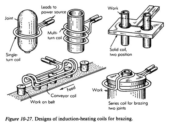
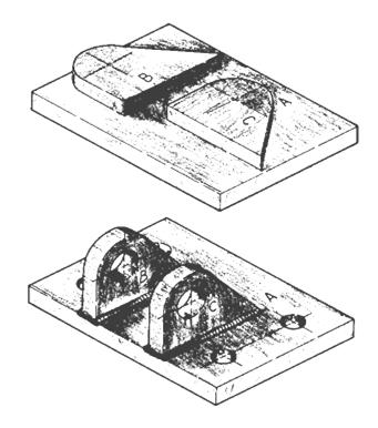
14 Tooling for Soldering and Brazing In a simple low- production process, the workman may hold a torch closer to the workpiece for a longer period of time. In a very precise high-production process, the instrumentation of a controlled atmospheretype furnace may be adjusted. Tooling for Soldering and Brazing Clearance between the surfaces being joined determines the amount of capillary attraction, the thickness of the alloy film, and consequently the strength of the finished joint. The best fitting condition would have about " ( mm) clearance. Larger clearances would lack sufficient capillary attraction, while smaller clearances would require expensive machining or fitting Tooling for Soldering and Brazing Many soldering and brazing operations are conducted without special tooling. As with mechanical joining methods, many work holding devices can be used to conveniently present the faces or areas to be joined. An electrical connecting plug can be conveniently held in a vise while a number of wires are soldered to its terminals. Tooling for Soldering and Brazing In many high-production assembly operations, parts are manually mated with a preformed brazing ring between them. They are then placed directly on the endless belt of a tunnel-type furnace, or on a gasheater ring fixture. If the shape of the workpiece is such that it will not support itself in an upright or convenient position, a simple nesting fixture may be required. Figure shows a simple nesting fixture in which two workpieces and a brazing ring have been placed Tooling for Soldering and Brazing The fixture can be mounted on a table while an operator applies heat with a hand torch. The same fixture could be mounted on a powered rotating base in the flame path of a fixed torch, while a feed mechanism would introduce wire solder at a predetermined rate (Figure 10-23). The same fixture could be attached in quantity to the belt of a tunnel furnace. A number of the fixtures could be attached to a rack for processing in a batch furnace


15 Examples

16
Materials & Processes in Manufacturing
 2003 Bill Young Materials & Processes in Manufacturing ME 151 Chapter 37 Arc Processes Chapter 38 Resistance Welding Chapter 39 Brazing and Soldering 1 Introduction Arc welding processes produce fusion
WELDING Topic and Contents Hours Marks
 Topic and Contents Hours Marks 3.1 Introduction 04 Marks Classification and selection of welding process. Working principle of Gas welding and types of flames. 3.2 Arc welding process 08 Marks Metal arc,
A Practical Design Guide for Welded Connections Part 1 Basic Concepts and Weld Symbols
 A Practical Design Guide for Welded Connections Part 1 Basic Concepts and Weld Symbols by James Doane, PhD, PE Course Overview This course is divided into 2 parts. Though it provides some basic concepts
Design for welding: Design recommendations
 Design for welding: Design recommendations Arc welding can be used to weld almost any kind of assembly, including even complex structures. Arc weldments use a wide variety of ferrous and non ferrous metals.
Welding Processes. Consumable Electrode. Non-Consumable Electrode. High Energy Beam. Fusion Welding Processes. SMAW Shielded Metal Arc Welding
 Fusion Consumable Electrode SMAW Shielded Metal Arc Welding GMAW Gas Metal Arc Welding SAW Submerged Arc Welding Non-Consumable Electrode GTAW Gas Tungsten Arc Welding PAW Plasma Arc Welding High Energy
Copyright 1999 Society of Manufacturing Engineers FUNDAMENTAL MANUFACTURING PROCESSES Welding NARRATION (VO):
:") Copyright 1999 Society of Manufacturing Engineers --- 1 --- FUNDAMENTAL MANUFACTURING PROCESSES Welding SCENE 1. CG: Fusion Welding Processes white text centered on black SCENE 2. tape 528, 14:18:33-14:18:52
Copyright 1999 Society of Manufacturing Engineers --- 1 --- FUNDAMENTAL MANUFACTURING PROCESSES Welding SCENE 1. CG: Fusion Welding Processes white text centered on black SCENE 2. tape 528, 14:18:33-14:18:52
Upon completion of this module
 Welding 1.4 Upon completion of this module 1. Cite the advantages of welding over other joining methods 2. Name & identify the various welding and cutting processes currently used in industry 3. Recognize
Chapter Outline. Joining Processes. Welding Processes. Oxyacetylene Welding. Fusion Welding Processes. Page 1. Welded Joints
 Joining Processes Chapter Outline R. Jerz 1 4/16/2006 R. Jerz 2 4/16/2006 Welding Processes Welded Joints Gas, electricity, or other heat source? Is electrode consumed? Is a filler material used? Is flux
Joining Processes R. Jerz
 Joining Processes R. Jerz 1 4/16/2006 Chapter Outline R. Jerz 2 4/16/2006 Welding Processes Gas, electricity, or other heat source? Is electrode consumed? Is a filler material used? Is flux used? Anything
Introduction to Welding Technology
 Introduction to Welding Technology Welding is a fabrication process used to join materials, usually metals or thermoplastics, together. During welding, the pieces to be joined (the workpieces) are melted
NAME 345 Welding Technology Lecture 09 SAW, ESW & Resistance Welding
 NAME 345 Welding Technology Lecture 09 Md. Habibur Rahman Lecturer Department of Naval Architecture & Marine Engineering Bangladesh University of Engineering & Technology Dhaka-1000, Bangladesh Submerged
Solid-State Welding Processes. Solid State Bonding 12/2/2009. Cold Welding
 Solid-State Welding Processes Solid-State Welding Processes Text Reference: Manufacturing Engineering and Technology, Kalpakjian & Schmid, 6/e, 2010 Chapter 31 Joining takes place without fusion at the
Module 4 Design for Assembly
 Module 4 Design for Assembly Lecture 2 Design for Welding-I Instructional Objective By the end of this lecture, the student will learn: (a) how a weld joint should be designed to improve the joint performance,
Dissimilar Metals DISSIMILAR METALS. Weld Tech News VOL 1. NO. 14
 Dissimilar Metals Weld Tech News VOL 1. NO. 14 WELD TECH NEWS is a newsletter for welders working primarily in maintenance and repair. Each issue contains useful information on materials (cast irons, steels,
Manufacturing Process-I Prof. Dr. D.K. Dwivedi Department of Mechanical and Industrial Engineering Indian Institute of Technology, Roorkee
 Manufacturing Process-I Prof. Dr. D.K. Dwivedi Department of Mechanical and Industrial Engineering Indian Institute of Technology, Roorkee Module - 03 Lecture - 02 Welding Process Classification Welcome
Solid-State Welding Processes
 Solid-State Welding Processes Text Reference: Manufacturing Engineering and Technology, Kalpakjian & Schmid, 6/e, 2010 Chapter 31 Solid-State State Welding Processes Joining takes place without fusion
Brazing & Braze Welding With Oxyacetylene
 Brazing & Braze Welding With Oxyacetylene 1 Definition A group of process that use heat to melt a metallic bonding agent, but not the base metal. The adhesion quality of the bonding agent binds the parts
WELDING TECHNOLOGY AND WELDING INSPECTION
 WELDING TECHNOLOGY AND WELDING INSPECTION PRESENTED BY: GOPAL KUMAR CHOUDHARY SVL ENGINEERING SERVICES CHENNAI CONTENTS: DEFINATION TYPES OF WELDING ELECTRODE GEOMETRY EQUIPMENT QUALITY PROCESS SAFETY
LIST OF PUBLISHED STANDARDS
 Report : 08-04-0 ost entre(s) : % Page o : Of 6 LST OF PUBLSHED STDRDS Total ount: 78 ommittee umber SS umber nt pproved mendment SBS/T 044 SS 44:009/SO 544:00 Welding consumables - Technical delivery
RESISTANCE WELDING MANUAL
 FTZSTSTA RWMA RESISTANCE WELDING MANUAL Revised Fourth Edition RWMA CONTENTS PREFACE ACKNOWLEDGEMENTS Section 1 PROCESSES Fundamentals Of Resistance Welding ;M INTRODUCTION 1-1 RESISTANCE WELDING PROCESSES
CIMC: Introduction to Agricultural Power and Technology
 CIMC: Introduction to Agricultural Power and Technology Unit 3- Shielded Metal Arc Welding 1. Shielded Metal Arc Welding also goes by other names. Which of the following is another term for this type of
Common Oxy Fuel Industry Terms
 Common Oxy Fuel Industry Terms A ACETYLENE Gas composed of two parts of carbon and two parts of hydrogen When burned in the atmosphere of oxygen, it produces one of the highest flame temperatures obtainable.
A METALCUTTING TECHNICAL ARTICLE BETTER TOGETHER: Non Defective Bonding of Resistance Spot Welding Electrodes
 A METALCUTTING TECHNICAL ARTICLE BETTER TOGETHER: Non Defective Bonding of Resistance Spot Welding Electrodes CONTENTS 1. INTRODUCTION 3 2. TRADITIONAL METHODS OF ELECTRODE BONDING 4 3. PROBLEMS WITH TRADITIONAL
Kasetsart University. INDT0204: Welding. Types of Welding
 Types of Welding Fusion Welding (Chap. 27) Oxyfuel Gas Welding Arc-Welding Processes Consumable-Electrode Nonconsumable-Electrode Others Electron-Beam Welding Laser-Beam Welding Solid State Welding (Chap.
Manufacturing Process II. Welding Processes-1
 Manufacturing Process II Welding Processes-1 1. Introduction: The term joining is generally used for welding, brazing, soldering, and adhesive bonding, which form a permanent joint between the parts a
PREVIEW COPY. Welding Principles. Table of Contents. Fundamentals of Welding...3. Oxyfuel Welding Equipment...35
 Welding Principles Table of Contents Lesson One Lesson Two Lesson Three Fundamentals of Welding...3 Welding Safety...19 Oxyfuel Welding Equipment...35 Lesson Four Arc Welding Equipment...53 Lesson Five
CLASSIFIATION OF WELDING PROCESSES
 Exp03: Welding Welding Welding is an art of joining metals by heating and then pressing together. Welding is a method of joining metals in which heat and/or pressure are applied to the area of contact
COMPARISON OF WELDING/BONDING METHODS
 TYPE OF WELDING/BONDING Adhesive Bonding Diffusion Welding Electron Beam Welding Explosive Welding SUMMARY ADVANTAGES DISADVANTAGES Bond is established through use of an intermediate adhesive layer applied
Manufacturing Process - I Prof. Dr. D.K. Dwivedi Department of Mechanical & Industrial Engineering Indian Institute of Technology, Roorkee
 Manufacturing Process - I Prof. Dr. D.K. Dwivedi Department of Mechanical & Industrial Engineering Indian Institute of Technology, Roorkee Module - 3 Lecture - 11 Tungsten Inert Gas Welding Part 1 Welcome
Brazing & Soldering. Brazing, Soldering, Adhesive-Bonding and Mechanical-Fastening. Brazing 12/2/2009
 Brazing, Soldering, Adhesive-Bonding and Mechanical-Fastening Processes Text Reference: Manufacturing Engineering and Technology, Kalpakjian & Schmid, 6/e, 2010 Chapter 32 Brazing & Soldering Joining processes
Fundamentals of Design for Welding. Kelly Bramble 32.1
 Fundamentals of Design for Welding Kelly Bramble 32.1 Fundamentals of Design for Welding Copyright, Engineers Edge, LLC www.engineersedge.com All rights reserved. No part of this training program may be
Welding Engineering Dr. D. K. Dwivedi Department of Mechanical & Industrial Engineering Indian Institute of Technology, Roorkee
 Welding Engineering Dr. D. K. Dwivedi Department of Mechanical & Industrial Engineering Indian Institute of Technology, Roorkee Module - 1 Introduction Lecture - 2 Classification of Welding Processes -
Resistance Welding Principle
 Resistance Welding Principle In resistance welding heat is generated by the electrical resistance of the work pieces and the interface between them. Pressure is supplied externally and is varied throughout
NAME 345 Welding Technology Lecture 07 Shielded Metal Arc Welding (SMAW)
") NAME 345 Welding Technology Lecture 07 Shielded Metal Arc Welding (SMAW) Md. Habibur Rahman Lecturer Department of Naval Architecture & Marine Engineering Bangladesh University of Engineering & Technology
NAME 345 Welding Technology Lecture 07 Shielded Metal Arc Welding (SMAW) Md. Habibur Rahman Lecturer Department of Naval Architecture & Marine Engineering Bangladesh University of Engineering & Technology
Beveling procedures and beveling machines beveling, a quick overview 1
 Beveling procedures and beveling machines 2018 beveling, a quick overview 1 Index 1. Fields of application S. 3 2. Welding procedures S. 8 3. Weld forms S. 9 4. Geometry of a bevel S. 13 5. User groups
Structure of Metals 1
 1 Structure of Metals Metals Basic Structure (Review) Property High stiffness, better toughness, good electrical conductivity, good thermal conductivity Why metals have these nice properties - structures
4/19/2018. The heat generated for welding comes from an arc
 Foundations of Agriculture The heat generated for welding comes from an arc Develops when electricity jumps across an air gap between the end of an electrode and the base metal. A. Alternating Current
Introduction to Joining Processes
 1. CLASSIFICATION OF JOINING METHODS The three basic options available for assembly and joining of engineering components may be designated: 1. mechanical 2. chemical 3. physical Some familiar examples:
Resistance Welding. Resistance Welding (RW)
") Resistance Welding (RW) Resistance Welding 1 Resistance Welding is a welding process, in which work pieces are welded due to a combination of a pressure applied to them and a localized heat generated by
Resistance Welding (RW) Resistance Welding 1 Resistance Welding is a welding process, in which work pieces are welded due to a combination of a pressure applied to them and a localized heat generated by
Casting, Forming & Welding
 Casting, Forming & Welding (ME31007) Jinu Paul Dept. of Mechanical Engineering CFW- Welding marks distribution CFW Total Marks = 100 Casting =33, Forming = 33, Welding =33 End semester exam 50 % Mid semester
Module - 4 Advanced Welding Processes Lecture - 1 Submerged Arc Welding (SAW)
") Advanced Manufacturing Processes Prof. Dr. Apurbba Kumar Sharma Department of Mechanical and Industrial Engineering Indian Institute of Technology, Roorkee Module - 4 Advanced Welding Processes Lecture
Advanced Manufacturing Processes Prof. Dr. Apurbba Kumar Sharma Department of Mechanical and Industrial Engineering Indian Institute of Technology, Roorkee Module - 4 Advanced Welding Processes Lecture
PULSED LASER WELDING
 PULSED LASER WELDING Girish P. Kelkar, Ph.D. Girish Kelkar, Ph.D, WJM Technologies, Cerritos, CA 90703, USA Laser welding is finding growing acceptance in field of manufacturing as price of lasers have
Fundamentals of Joining
 Fundamentals of Joining Chapter 30 30.1 Introduction to Consolidation Processes Consolidation Processes consist of Welding Brazing Soldering Fasteners Adhesives Shrink Fits Slots and Tabs Each Process
Lecture 23. Chapter 30 Fusion Welding Processes. Introduction. Two pieces are joined together by the application of heat
 Lecture 23 Chapter 30 Fusion Welding Processes Introduction Fusion welding Two pieces are joined together by the application of heat Melting and fusing the interface Filler metal Extra metal added (melted)
TIG Welding. Kyle Westmoreland Brad Watson
 TIG Welding Kyle Westmoreland Brad Watson Overview TIG=Tungsten Inert Gas Welding Uses a tungsten electrode to produce an electric arc. The weld is shielded by a gas typically argon and a welding rod is
VAC AERO International Inc. Training Manual BASIC HEAT TREATING
 Training Manual BASIC HEAT TREATING What is Heat Treating? -1- BASIC HEAT TREATING Heat treating is a process involving controlled heating and cooling of a solid metal to produce a desired change in the
Introduction. Online course on Analysis and Modelling of Welding. G. Phanikumar Dept. of MME, IIT Madras
 Introduction Online course on Analysis and Modelling of Welding G. Phanikumar Dept. of MME, IIT Madras Classification of Manufacturing Processes Manufacturing Processes Ingot Casting Shape Casting Power
Cutting Tool Materials and Cutting Fluids. Dr. Mohammad Abuhaiba
 Cutting Tool Materials and Cutting Fluids HomeWork #2 22.37 obtain data on the thermal properties of various commonly used cutting fluids. Identify those which are basically effective coolants and those
Welding Engineering Prof. Dr. D. K. Dwivedi Department of Mechanical and Industrial Engineering Indian Institute of Technology, Roorkee
 Welding Engineering Prof. Dr. D. K. Dwivedi Department of Mechanical and Industrial Engineering Indian Institute of Technology, Roorkee Module - 4 Arc Welding Processes Lecture - 1 SMAW- 1 So, dear students,
The principle Of Tungsten Inert Gas (TIG) Welding Process
 Welding Process") The principle Of Tungsten Inert Gas (TIG) Welding Process This chapter presents the principle of tungsten inert gas (TIG) welding process besides important components of TIG welding system and their role.
The principle Of Tungsten Inert Gas (TIG) Welding Process This chapter presents the principle of tungsten inert gas (TIG) welding process besides important components of TIG welding system and their role.
EML 2322L -- MAE Design and Manufacturing Laboratory. Welding
 EML 2322L -- MAE Design and Manufacturing Laboratory Welding Intro to Welding A weld is made when separate pieces of material to be joined combine and form one piece when heated to a temperature high enough
Lecture - 01 Introduction: Manufacturing and Joining
 Joining Technologies of Commercial Importance Dr. D. K. Dwivedi Department of Mechanical and Industrial Engineering Indian Institute of Technology Roorkee Lecture - 01 Introduction: Manufacturing and Joining
Residual Stresses and Distortion in Weldments
 Residual Stresses and Distortion in Weldments By: Aziz Shafiei Residual Stresses 1 Causes of Residual Stresses Residual stresses in metal structures occur for many reasons during various manufacturing
ANSI/AWS D R An American National Standard. Recommended Practices for Root Pass Welding of Pipe Without Backing
 ANSI/AWS D10.11-87R An American National Standard Recommended Practices for Root Pass Welding of Pipe Without Backing Key WordS Root pass welding, pipe, gas purging, consumable inserts, gas tungsten arc,
 VALLIAMMAI ENGINEERING COLLEGE DEPARTMENT OF MECHANICAL ENGINEERING ME 6302 MANUFACTURING TECHNOLOGY 1 (QUESTION BANK) I-METAL CASTING PROCESSES PART-A (2 MARKS) 1.Name any four types of commonly used
Chapter 31. Solid-State Welding Processes
 Chapter 31 Solid-State Welding Processes Roll Bonding Figure 31.1 Schematic illustration of the roll bonding or cladding process. Ultrasonic Welding Figure 31.2 (a) Components of an ultrasonic welding
MANUAL METAL ARC (MMA) STICK WELDING
 STICK WELDING") AN INTRODUCTION TO MANUAL METAL ARC (MMA) STICK WELDING Proline Welding Supplies sales@prolinewelding.com 0800 699 353 WARNING: This document contains general information about the topic discussed herein.
AN INTRODUCTION TO MANUAL METAL ARC (MMA) STICK WELDING Proline Welding Supplies sales@prolinewelding.com 0800 699 353 WARNING: This document contains general information about the topic discussed herein.
b) provide evidence of his qualifications and practical experience in welding.
 provide evidence of his qualifications and practical experience in welding.") NEPALESE CIVIL AIRWORTHINESS REQUIREMENTS SECTION D APPROVAL PROCEDURES CHAPTER D.6 ISSUE 1 NOVEMBER 1994 1. GENERAL WELDERS 1.1 This chapter is applicable to persons who weld parts which are essential
NEPALESE CIVIL AIRWORTHINESS REQUIREMENTS SECTION D APPROVAL PROCEDURES CHAPTER D.6 ISSUE 1 NOVEMBER 1994 1. GENERAL WELDERS 1.1 This chapter is applicable to persons who weld parts which are essential
!!!! WARNING!!!! WELDING FUMES AND GASES CAN BE DANGEROUS TO YOUR HEALTH.
 CAREFULLY!!!! WARNING!!!! CAREFULLY WELDING FUMES AND GASES CAN BE DANGEROUS TO YOUR HEALTH. BEFORE USING THIS PRODUCT THE WELDER (END-USER) MUST READ AND UNDERSTAND THE COMPLETE PRODUCT WARNING LABEL
Division 11 - Equipment Section 11401
 PART 1 - GENERAL 1.1 GENERAL A. Division 1 General Requirements applies and becomes a part of this Section of the Specification as fully as if repeated herein. B. Items of equipment which are included
The hardenable alloys contain copper (Cu), magnesium and silicon (Mg + Si), or zinc and magnesium (Zn + Mg).
, magnesium and silicon (Mg + Si), or zinc and magnesium (Zn + Mg).") Welding of Aluminium Much of the successful art of aluminium welding is to be found in careful thought and preparation even before welding is started. Through correct preparation, it is easier to avoid
Welding of Aluminium Much of the successful art of aluminium welding is to be found in careful thought and preparation even before welding is started. Through correct preparation, it is easier to avoid
Advancements in Laser Welding Technology
 June 015 [Volume 1, Issue 1] Advancements in Laser Welding Technology Broadening our Horizons Contents Special Interest Articles We are proud to announce the Broadening our Horizons 1 purchase of a brand
GRINDING AND OTHER ABRASIVE PROCESSES
 GRINDING AND OTHER ABRASIVE PROCESSES Grinding Related Abrasive Process Abrasive Machining Material removal by action of hard, abrasive particles usually in the form of a bonded wheel Generally used as
HOBART BROTHERS Metal core Process. Basics of Welding Metal Cored Wires
 HOBART BROTHERS Metal core Process Basics of Welding Metal Cored Wires AWS Metal Core Classification AWS A5.18 E 70 C-6 M Electrode Tensile (ksi) Composite Impact Strength 3=20 ft. lbs. @ 0 F 6=20 ft.
Design of Machine Elements I Prof. G. Chakraborty Department of Mechanical Engineering Indian Institute of Technology Kharagpur
 Design of Machine Elements I Prof. G. Chakraborty Department of Mechanical Engineering Indian Institute of Technology Kharagpur Lecture - 23 Design of Welded Joints-I Dear Student, let us begin lectures
CHAPTER 28. Solid-State Welding Processes. Kalpakjian Schmid Manufacturing Engineering and Technology 2001 Prentice-Hall Page 28-1
 CHAPTER 28 Solid-State Welding Processes Manufacturing Engineering and Technology 2001 Prentice-Hall Page 28-1 Roll Bonding Figure 28.1 Schematic illustration of the roll bonding, or cladding, process
SECOND SEMESTER DIPLOMA EXAMINATION IN MECHANICAL ENGINEERING- OCTOBER, 2013 MANUFACTURING PROCESS PART-A
 SECOND SEMESTER DIPLOMA EXAMINATION IN MECHANICAL ENGINEERING- OCTOBER, 2013 1. Give any two advantages of ultrasonic inspection test. i. High sensitivity and portability ii. Non hazardous operations MANUFACTURING
3/26/2015. Processes of Arc Welding. Kate Gilland
 3/26/2015 Processes of Arc Welding Kate Gilland Processes of Arc Welding Introduction Welding is a powerful technological advance. It allows for things to be conjoined that may have not been thought to
SHRI ANGALAMMAN COLLEGE OF ENGINEERING AND TECHNOLOGY (An ISO 9001:2008 Certified Institution) Siruganoor, Tiruchirappalli
 Siruganoor, Tiruchirappalli") SHRI ANGALAMMAN COLLEGE OF ENGINEERING AND TECHNOLOGY (An ISO 9001:2008 Certified Institution) Siruganoor, Tiruchirappalli 621 105. Department of Mechanical Engineering PR 1204--MANUFACTURING TECHNOLOGY
SHRI ANGALAMMAN COLLEGE OF ENGINEERING AND TECHNOLOGY (An ISO 9001:2008 Certified Institution) Siruganoor, Tiruchirappalli 621 105. Department of Mechanical Engineering PR 1204--MANUFACTURING TECHNOLOGY
Sn-Pb plating or Tin plating
 2/14 Unit mm L a a Code letter Dimension L 2..2 W 1.25.2 W t a b.4.1.4.2.4.2 t b b Fig.1 Construction and dimensions NOTE : Resistive element Electrode Protective coat Substrate Nichrome alloy thin film
ELECTRIC WELDING. Types Resistance, Electric arc, gas welding. Ultrasonic, Welding electrodes of various metals, Defects in welding.
 ELECTRIC WELDING Types Resistance, Electric arc, gas welding. Ultrasonic, Welding electrodes of various metals, Defects in welding. Introduction Welding is the process of joining two pieces of metal or
SECOND SEMESTER DIPLOMA EXAMINATION IN MECHANICAL ENGINEERING- MARCH, 2015 MANUFACTURING PROCESS PART-A
 SECOND SEMESTER DIPLOMA EXAMINATION IN MECHANICAL ENGINEERING- MARCH, 2015 MANUFACTURING PROCESS PART-A 1. Define hardness. It is the ability of a material to resist indentation or surface abrasion 2.
Chapter 14: Metal-Forging Processes and Equipments
 Manufacturing Engineering Technology in SI Units, 6 th Edition Chapter 14: Metal-Forging Processes and Equipments Chapter Outline Introduction Open-die Forging Impression-die and Closed-die Forging Various
NAME 345 Welding Technology Lecture 03 (Welding Joint Design)
") NAME 345 Welding Technology Lecture 03 (Welding Joint Design) Md. Habibur Rahman Lecturer Department of Naval Architecture & Marine Engineering Bangladesh University of Engineering & Technology Dhaka-1000,
NAME 345 Welding Technology Lecture 03 (Welding Joint Design) Md. Habibur Rahman Lecturer Department of Naval Architecture & Marine Engineering Bangladesh University of Engineering & Technology Dhaka-1000,
1 - Introduction and Overview of Manufacturing
 1 - Introduction and Overview of Manufacturing Manufacturing Processes - 2, IE-352 Ahmed M El-Sherbeeny, PhD Spring-2015 1 Chapter 1 INTRODUCTION AND OVERVIEW OF MANUFACTURING 1. What is Manufacturing?
FOREWORD. Communication on these practices is most welcome. MECHELONIC. The birth of Mechelonic took place a decade ago in January 1972.
 FOREWORD Mechelonic Welders Pvt Ltd This booklet has been prepared by our technical team in order to guide the Industries employing Resistance Welding Technology in their line of manufacture. We have tried
DOWNLOAD PDF SMAW : BEADS AND FILLET WELDS
 Chapter 1 : SMAW Fillet Welds?!!! - Miller Welding Discussion Forums View Notes - SMAW -beads and fillet weldsterm: Definition: wire brush or grinder used to remove heavy mill scale or corrosion from coupons
HANGERS AND SUPPORTS FOR HVAC PIPING AND EQUIPMENT SECTION HANGERS AND SUPPORTS FOR HVAC PIPING AND EQUIPMENT
 13686.00 HANGERS AND SUPPORTS FOR HVAC PIPING AND EQUIPMENT 230529-1 SECTION 230529 - HANGERS AND SUPPORTS FOR HVAC PIPING AND EQUIPMENT 1.1 SUMMARY A. Section Includes: 1. Metal pipe hangers and supports.
ATI 718 ATI 718. Technical Data Sheet. Nickel-Base Superalloy INTRODUCTION FORMS AND CONDITIONS AVAILABLE SPECIFICATIONS. (UNS Designation N07718)
") ATI 718 Nickel-Base Superalloy (UNS Designation N07718) INTRODUCTION ATI 718 alloy (N07718) is an austenitic nickel-base superalloy which is used in applications requiring high strength to approximately
ATI 718 Nickel-Base Superalloy (UNS Designation N07718) INTRODUCTION ATI 718 alloy (N07718) is an austenitic nickel-base superalloy which is used in applications requiring high strength to approximately
3 TIG welding. 3.1 A description of the method. 3.2 Equipment
 3 TIG welding 3.1 A description of the method TIG welding (also called Gas Tungsten Arc Welding, GTAW) involves striking an arc between a non-consumable tungsten electrode and the workpiece. The weld pool
Agenda. Hitsaustekniikka Kon Gas Metal Arc Welding Conventional control (solid wire) - Fundaments
 - Fundaments") Department of Engineering Design and Production Master Degree in Mechanical Engineering Hitsaustekniikka Kon-67.4200 Gas Metal Arc Welding Conventional control (solid wire) - Fundaments Materials Joining
Department of Engineering Design and Production Master Degree in Mechanical Engineering Hitsaustekniikka Kon-67.4200 Gas Metal Arc Welding Conventional control (solid wire) - Fundaments Materials Joining
MANUFACTURING TECHNOLOGY - I UNIT-1 TWO MARKS
 MANUFACTURING TECHNOLOGY - I UNIT-1 TWO MARKS 1. Define foundry? 2. Define casting. 3. Define mould. 4. Define pattern 5. Name the various pattern materials? 6. How is distortion allowances is made on
PRESTON HEALTH SERVICES ARCHITECT'S NO MITCHELL-HOLLINGSWORTH NURSING & REHAB ADPH #B
 SECTION 05 5213 - PIPE RAILINGS PART 1 - GENERAL 1.1 RELATED DOCUMENTS A. Drawings and general provisions of the Contract, including General and Supplementary Conditions and Division 01 Specification Sections,
Manufacturing Process - I Dr. D. K. Dwivedi Department of Mechanical and Industrial Engineering Indian Institute of Technology, Roorkee
 Manufacturing Process - I Dr. D. K. Dwivedi Department of Mechanical and Industrial Engineering Indian Institute of Technology, Roorkee Module - 3 Lecture - 14 Reaction in Weld Region & Welding Defects
Manufacturing Process - I
 Manufacturing Process - I UNIT II Metal Forming Processes Prepared By Prof. Shinde Vishal Vasant Assistant Professor Dept. of Mechanical Engg. NDMVP S Karmaveer Baburao Thakare College of Engg. Nashik
KCWONG. Shielded Metal Arc Welding (SMAW) Gas Metal Arc Welding (GMAW/MIG) Flux-cored Arc Welding (FCAW) Gas Tungsten Arc Welding (GTAW/TIG) KCWONG
 Gas Metal Arc Welding (GMAW/MIG) Flux-cored Arc Welding (FCAW) Gas Tungsten Arc Welding (GTAW/TIG) KCWONG") 1 Shielded Metal Arc Welding (SMAW) Gas Metal Arc Welding (GMAW/MIG) Flux-cored Arc Welding (FCAW) Gas Tungsten Arc Welding (GTAW/TIG) 2 Working Principle Equipment Filler metals Advantages Limitation
1 Shielded Metal Arc Welding (SMAW) Gas Metal Arc Welding (GMAW/MIG) Flux-cored Arc Welding (FCAW) Gas Tungsten Arc Welding (GTAW/TIG) 2 Working Principle Equipment Filler metals Advantages Limitation
Chapter 32 Resistance Welding and Solid State Welding. Materials Processing. Classification of Processes. MET Manufacturing Processes
 MET 33800 Manufacturing Processes Chapter 32 Resistance Welding and Solid State Welding Before you begin: Turn on the sound on your computer. There is audio to accompany this presentation. Materials Processing
ZIRCALOY WELDING IN OPAL REACTOR REFLECTOR VESSEL
 ZIRCALOY WELDING IN OPAL REACTOR REFLECTOR VESSEL Ortiz L. and Martínez R. INVAP SE, S. C. de Bariloche, Río Negro, Argentina Abstract This paper describes the development of the Zircaloy 4 welding processes
Laser Diodes System for Flexible Manufacturing Authors: John M. Haake, Crystal M. Cook and Mark S. Zediker
 Laser Diodes System for Flexible Manufacturing Authors: John M. Haake, Crystal M. Cook and Mark S. Zediker Introduction Industrial laser systems based on high power laser diodes are now available with
HOW TO SELECT A RESISTANCE WELDER
 HOW TO SELECT A RESISTANCE WELDER Despite the fact that resistance welding is one of the most widely used joining processes in the sheet metal fabricating industry, the proper selection of a resistance
Getting Started with Welding
 Getting Started with Welding With the biochar crew at Living Web Farms Introduction Who we are What we re going to talk about: Basic concepts of working with metals, predominantly steel How to protect
Initial Reliability Requirements
 Summary Initial Reliability Requirements Part, Process or Characteristic Major Minor Raw Material 92 90 Machined Parts (General Features) 97 92 Sheet metal fabrication 92 90 Composite Parts 97 90 Fastener
Work Holding. Manufacturing Tooling 4. Work Holding Principles. Nageswara Rao Posinasetti
 Manufacturing Tooling 4. Work Holding Principles Nageswara Rao Posinasetti Work Holding Work holder includes all devices that hold, grip, or chuck a work piece to perform a manufacturing operation. February
QForm. Form3D. Advanced software for forging simulation
 QForm Form3D Advanced software for forging simulation The goals of forging technology : Make the parts of the required shape Provide required properties Do it in time and at the lowest cost Forging process
Technical Data & Welding Guidelines for Ferralium 255SD50 Super Duplex Stainless Steel
 Technical Data & Welding Guidelines for Ferralium 255SD50 Super Duplex Stainless Steel Technical Data & Welding Guidelines FERRALIUM Alloy 255 Ferralium 255SD50 Super Duplex Stainless Steel General FERRALIUM
Spot Welding Instrumental technique. Soumabha Bag CY08D
 Spot W Instrumental technique Soumabha Bag CY08D021 09-02-13 Introduction: W is a fabrication or sculptural process that joins materials, usually metals, by causing coalescence. This is in contrast with
Roll Bonding or Roll Welding
 1 2 3 4 Roll Bonding or Roll Welding The pressure required for welding is applied through a pair of rolls Can be performed hot (Hot Roll Bonding) Surface preparation is important for interfacial bonding
PLASTICS TODAY THE MAGAZINE OF PLASTICS MANUFACTURING PRODUCTIVITY
 PLASTICS TODAY THE MAGAZINE OF PLASTICS MANUFACTURING PRODUCTIVITY Selecting the 'Right' Thermocouple: There Are More Choices Today Used every day by most processors, thermocouples tend to be taken for