Fabrication of Hydrogels with Controllable Heterogeneity in Stiffness
|
|
|
- Myron Haynes
- 6 years ago
- Views:
Transcription
1 Fabrication of Hydrogels with Controllable Heterogeneity in Stiffness Project Number: QW A Major Qualifying Project Report: Submitted to the Faculty Of the WORCESTER POLYTECHNIC INSTITUTE In partial fulfillment of the requirements for the Degree of Bachelor of Science By Olivia Hart Kathleen Hodge Margaret McDonough Amanda Ryan Date: May 2014 Approved: Professor Qi Wen 1. Hydrogel 2. Stiffness 3. Heterogeneity Professor Sakthikumar Ambady
2 ii Abstract Tissues in the body are heterogeneous in stiffness, yet there has been little investigation regarding how cells work cooperatively in heterogeneous environments. The mechanical properties of the extracellular matrix can affect cell morphology, proliferation, differentiation, and migration. Polyacrylamide hydrogels with regions of varying stiffnesses were fabricated to better represent in vivo tumor-like conditions to study cell behavior and cell-cell interactions. A method to fabricate hydrogels with uniform thickness and controllable heterogeneity in stiffness was developed. Atomic force microscopy was used to characterize stiffness of the fabricated hydrogels. NIH 3T3 cells were plated on the hydrogels and experimental tests were conducted to quantify cell viability and morphology.
3 iii Table of Contents Abstract... ii Table of Figures... vi Table of Tables... vii Authorship... viii Acknowledgements... ix Chapter 1 : Introduction... 1 Chapter 2 : Literature Review... 3 Extra Cellular Matrix... 3 Stiffness In Vitro and In Vivo... 4 Effects of Tumors on Cellular Environment... 5 Hydrogels... 5 Polyacrylamide... 6 Poly(ethylene glycol) diacrylate (PEG)... 7 Stiffening Methods... 8 UV Crosslinking... 8 Irgacure Photoinitiators... 8 Controlling the Regions of Stiffness... 9 Transglutaminases... 9 Measuring Techniques Atomic Force Microscopy Magnetic Resonance Elastography Chapter 3 : Project Strategy Initial Client Statement Objectives & Constraints Revised Client Statement Project Approach Technical Financial Chapter 4 : Alternative Designs Hydrogel Protocol... 21
4 iv Needs Analysis Functions and Specifications Preliminary Testing Fabrication System Needs Analysis Functions and Specifications Conceptual Designs Alternative Designs Feasibility Studies Decisions Chapter 5 : Design Verification Hydrogel Fabrication Protocol Preparing Coverslips Preparing Gel Solution Gel Fabrication Hydrogel Degradation Biocompatibility Testing Hydrogel Characterization: Atomic Force Microscopy (AFM) Data Homogeneous Gels Heterogeneous Gels Proof of Concept: Cell Testing Fluorescein o-acrylate Incorporation Chapter 6 : Discussion Economics Environmental & Societal Impact Political Ramifications & Ethical Concern Health and Safety Issues Manufacturability Chapter 7 : Final Design and Validation Chapter 8 : Conclusions and Recommendations References... 52
5 v Appendix A: CAD Drawings Appendix B: Alternative Mask Designs... 61
6 vi Table of Figures Figure 2-1: Atomic Force Microscopy Setup Figure 2-2: Magnetic Resonance Elastography Figure 3-1: Objectives Tree Figure 3-2: Pairwise Comparison Chart Figure 4-1: Chamber with Clips Figure 4-2: (A) PDMS Chamber Design, (B) Improved PDMS Chamber Design Figure 4-3: Original Chamber Design Figure 4-4: Chamber for 10 with thin wall Figure 4-5: Chamber for 10 with thin wall Figure 5-1: Polyacrylamide Hydrogel Figure 5-2: Gel Stiffness vs. UV Exposure Figure 5-3: Stiffness Profile Figure 5-4: Stiffness Profile Figure 5-5: NIH 3T3-Hard region (12kPa)-20X DAPI/Phalloidin Figure 5-6: NIH 3T3-Soft region (2kPa)-20X DAPI/Phalloidin Figure 5-7: NIH 3T3-Heterogeneous Gel (2-12kPa)-5X Brightfield Figure 8-1: Overarching Goals... 50
7 vii Table of Tables Table 4-1: Metal Printing Prices Table 5-1: Acrylamide/Bis-Acrylamide Concentrations Table 6-1: Cost Breakdown... 44
8 viii Authorship All authors contributed equally to the writing and editing of this report.
9 ix Acknowledgements The team would like to thank Worcester Polytechnic Institute, Department of Biomedical Engineering, Lisa Wall (Lab Manager, Biomedical Engineering), Gawain Thomas (PhD Student, Physics) for his time and talent with Atomic Force Microscopy, and our advisors, Professor Qi Wen (Physics) and Professor Sakthikumar Ambady (Biomedical Engineering) for their guidance and assistance throughout the course of this project.
10 1 Chapter 1 : Introduction Tissues in the body are heterogeneous in stiffness, yet there has been little investigation regarding how cells work cooperatively in heterogeneous environments. Stiffness of the extracellular matrix (ECM) in body tissue affects cell adhesion, migration, differentiation, and morphology. Because ECM stiffness is not uniform across tissues, cells may not all behave in the same way. Current in vitro systems used to study cell behavior are not representative of biological tissue. If tissue culture substrates better mimicked specific cellular environments, further research and experimentation could be conducted that more accurately represents cell behavior in vivo. Hydrogels have recently gained popularity as substrates in cell and tissue engineering research. These networks of highly hydrophilic polymer chains have mechanical properties similar to body tissue, and are therefore becoming more widely used as a substrate. Hydrogels have tunable mechanical properties and show promise to develop into research tools that better represent in vivo conditions. The goal of this project was to develop a system to fabricate hydrogels that more accurately represent in vivo conditions. Specifically, a cancerous, tumor-like environment. By developing a hydrogel that mimics the stiffness of tumors in the body, further research can be conducted regarding what specific changes in adhesion, morphology, migration, differentiation, and proliferation cells undergo and how far from the stiffness area these changes can be seen. Background research was conducted to narrow down and ultimately select viable polymers for hydrogel fabrication. Laboratory experiments were performed to select the most effective crosslinking method for altering regions of stiffness within the hydrogel. Tests were performed to verify stability and quantify stiffness by measuring the elastic modulus of the
11 2 hydrogel. Cells were plated on the hydrogel and cell adhesion, proliferation, and morphology were observed. The following report will include a literature review, in Chapter 2, providing background information about the ECM and the effects of tumors on cell behavior. Information on fabrication processes and methods to measure hydrogel properties will also be discussed. Chapter 3 will discuss the client statement, objectives, constraints, and overall project approach. Design alternatives and verification of our product design will be explained in Chapters 4 and 5. The results of the design verification will be discussed in Chapter 6 and Chapter 7 will detail our final product design and validation. Finally, conclusions and recommendations for future work are discussed in Chapter 8.
12 3 Chapter 2 : Literature Review Extra Cellular Matrix A significant volume of tissue in the body is not composed of cells, but a complex system of macromolecules known as the extracellular matrix (ECM) (Alberts et al, 2002). The ECM is composed of locally secreted polysaccharides and fibrous proteins organized into a network outside the cells. Cells in their natural biological environment are anchorage dependent and adhere to this matrix, which functions to support cellular structure and intercellular communication (Sternlicht et al, 2001). Properties of the ECM influence aspects of cell behavior such as cell adhesion, morphology, migration, proliferation, and differentiation. Cell behavior in response to mechanical properties of the ECM plays a role in processes ranging from embryogenesis (Ingber et al, 2006) to the pathogenesis of disease states. ECM stiffness in particular is a factor in cellular function. Cells have the ability to grow and develop on a range of stiffness. The ECM stiffness however, impacts the ways in which cells behave. Changes in stiffness have been associated with fibrosis, cancer, and cardiovascular disease (Cretu et al, 2010). A normal tissue cell anchors and pulls on its surroundings; this processes depends on myosin-based contractility and cell-ecm adhesions. Cells apply forces to the substrate and respond to the resistance it senses, through cytoskeleton organization. This process occurs whether resistance is from tissue matrix, synthetic substrate, or adjacent cells. The cell responds to this resistance by adjusting its adhesions, cytoskeleton, and overall state (Dischter et al, 2005). To gain a better understanding of how tissue cells like fibroblasts, myocytes, and neurons sense ECM stiffness, quantitative studies where cells adhere to gels elasticity similar to tissue have been carried out (Komatsu et al, 2010). Although there is cell-to-cell variability, and
13 4 cellular force response relationships are not linear, generally cells on stiffer substrates have stiffer, more organized cytoskeletons and more stable focal adhesions (Wells, 2008). The feedback of local matrix stiffness on cell state likely has important implications for development, differentiation, disease, and regeneration. Stiffness In Vitro and In Vivo Young s modulus, also known as elastic modulus (E), is defined as resistance to deformation. This value can be measured by applying force to a defined area in a material (stress) and calculating the resulting change in length (strain). The slope of the stress versus strain plot is the stiffness value, also known as the elastic modulus (Hibbler, 2012). Atomic Force Microscopy (AFM) is a common microindentation technique used to measure E values on a small scale, such as individual cells (Wells, 2008). AFM technique will be discussed in more detail in following sections. The elastic modulus of living tissues varies over orders of magnitude. The E of cells is largely determined by actin-myosin based cytoskeletons. The brain for example, has an E of several hundred pascals, the E of muscle is around 12 kpa, and tendon and cartilage is in the range of megapascals. When compared to the stiffness of tissue culture plastic or glass with an E in the gigapascal range, it is apparent that these in vitro surfaces are significantly stiffer than any living tissue (Wells, 2008). Cells in culture are in an environment with mechanical conditions not physiologically similar to living tissue. Substantial differences in E raises concern that behaviors attributed to cells in culture including cytoskeletal organization, proliferation, and differentiation may not be representative of cell behavior in vivo.
14 5 Effects of Tumors on Cellular Environment Tumors are masses of abnormal cells that result from rapid and uncontrolled cell division. Two types of tumors exists, malignant (cancerous) and benign (noncancerous). Both of which can pose threats to surrounding tissues (Baba et al, 2007). Malignant tumors invade surrounding tissues and can further shed cells, enter the bloodstream, and invade tissues in various parts of the body. Tumors compete for nutrients and space with healthy tissues and can be fatal if left untreated. Benign tumors can also be detrimental to surrounding cells as they compress adjacent cells and inhibit cell function (Lerner et al, 2008). Tumors have been found to be stiffer than the tissue which surrounds it. Healthy breast tissue, for example has an elastic modulus of approximately 0.2kPa, while breast tumor stiffness is approximately 4kPa. Liver tissue ranges in stiffness ( Pa) however, diseased liver tissue can be as stiff as 15 kpa (Janmey et al, 2011). In studies of cancerous tissue it has been observed that when cells form tumors, forces are applied to surrounding cells. These forces change the mechanical properties of the cellular environment and can potentially change the fate of cells (Tee et al, 2011). The effects of stiffness and other mechanical properties on cell behavior has not been studied as extensively as chemical signals, however these properties continue to prove significant. Hydrogels Hydrogels are hydrophilic polymer chains, crosslinked to form an interconnected network resulting in an insoluble gel. Due their crosslinked structure, hydrogels can absorb several hundred up to one thousand times their dry weight in water giving them solid-like properties. This means hydrogels have a defined shape and mechanical properties, such as an elastic modulus. However, hydrogels also exhibit liquid-like properties such as the ability of
15 6 solute molecules to diffuse through the matrix. The properties of a hydrogel can be manipulated in a variety of ways. The modulus can be altered by increasing concentrations of a particular polymer or crosslinking agent, or by changing the density of crosslinking.a hydrogel can become irreversible by covalently crosslinking or reversible by being physically crosslinked. Degradability of the gel can be altered based on the selection of polymers or introduction of degradable crosslinks (Lee et al, 2004). Hydrogels are currently used in a variety of biomedical applications including soft contact lenses, drug delivery systems, wound healing, cartilage repair, and most recently as substrates for tissue engineering (Hoffman, 2012). The ability of a hydrogel to swell and retain water, its porous matrix, tunable mechanical properties, and biocompatibility, provides reason to further investigate gels for use as scaffolds and substrates on which to grow cells. Hydrogel properties are similar to soft biological tissue ECM making this material an ideal candidates for studying cells in vitro with in vivo properties accounted for (Jia, 2011). There are many possible combinations of materials that can be used (natural vs. synthetic, copolymer vs. homopolyer, crosslinking methods) in the fabrication of hydrogels for cell culture. The following section provides background for potential materials that have been chosen for the design of this hydrogel. Polyacrylamide Polyacrylamide has become a common material in hydrogel fabrication; this polymer also has many advantages in cell culture applications. By changing relative concentrations of the monomer acrylamide and crosslinker bis-acrylamide, the stiffness of the gel can be varied, allowing for a wide range of controllable mechanical properties (Tse et al, 2010). Polyacrylamide can form thin, translucent gels, ideal for observing cell interactions in culture.
16 7 In order to fabricate a polyacrylamide hydrogel, crosslinking is necessary. A unique trait of polyacrylamide hydrogels is the thermal solution-gel transition. At lower temperatures polyacrylamide can be a liquid; it solidifies, forming a gel, at body temperature. Polyacrylamide crosslinked hydrogels provide mechanical support throughout the gel, preventing excessive amounts of shrinkage from occurring (Muniz et al, 2001). Another advantage of polyacrylamide gels is that changing the mechanical properties will not alter hydrogel surface chemistry. This is important in cell culture studies that are trying to demonstrate cell dependence on ligand density, when cells are in movement. In cell culture it is critical that cells can adhere to the hydrogel. Nonspecific binding of cell surface receptors is generally negligible with polyacrylamide, meaning only adhesive molecules that are chosen may be attached to the surface of the gel. A protein coating such as collagen must be added to the surface of a polyacrylamide hydrogel to allow for cell adhesion (Tse et al, 2010). Polyacrylamide hydrogels are fabricated by combining different concentrations of acrylamide and bis-acrylamide, then polymerization is initiated through the use of chemical or photoinitiator compounds. These compounds aid in polymerization by binding the crosslinker, bis-acrylamide to the monomer acrylamide (Tse et al, 2010). Disadvantages of polyacrylamide include the inability to readily absorb proteins and a need to covalently bind proteins in order to form a hydrogel. Poly(ethylene glycol) diacrylate (PEG) Poly(ethylene glycol) (PEG) has been used extensively in hydrogel applications including tissue engineering, controlled drug release, and cell culture. Its high hydrophilicity, biocompatibility, and easily tunable mechanical properties makes it a very attractive candidate in hydrogel fabrication. Mechanical and swelling properties can be easily altered by changing the
17 8 PEG chain length or varying the degree of crosslinking with UV exposure (Beamish et al, 2010). PEG diacrylate utilizes a single component as both a crosslinker and the crosslinked chain. This creates a dense network of crosslinks without chemical reactants being absorbed and later released by the gel, potentially harming cells plated on it. Photopolymerization can be employed to form PEG hydrogels. Many studies have been conducted altering the ratio of PEG to water to adjust the swelling (Beamish et al, 2010). PEG does not absorb proteins and will not allow for cell attachment unless modified. Collagen, gelatin or another natural polymer must be added to the surface to allow cell adhesion. Stiffening Methods In addition to selecting a polymer with favorable mechanical properties, there are various techniques that can be employed not only to finely tune the properties of the bulk material, but also achieve controlled regions of stiffness required for this project. This section will focus on the use of ultraviolet (UV) light for crosslinking of polymer chains to increase stiffness. Alternative means of creating controlled regions of stiffness will also be explored. UV Crosslinking In a laboratory setting, ultra violet crosslinking is achieved using a UV lamp at a specific wavelength and a photoinitiator to activate a photo-reactive crosslinking reagent. By varying the wavelength of ultraviolet light and the amount of exposure time, one can finely tune crosslinking within a material (Thermo Scientific, 2013). Irgacure Photoinitiators Irgacure photoinitiator is a component of the UV curing process. When added to solution, 1-[4-(2-hydroxyethoxy)-phenyl]-2-hydroxy-2-methyl-1-propanone, also known as Irgacure 2959, decomposes into free radicals and initiates the polymerization process due to the
18 9 absorption of light. This photoinitiated polymerization process involves UV light of a wavelength of 365nm which catalyzes free radical polymerization of acrylamide and bisacrylamide by cleaving the Irgacure 2959 molecules into free radicals. Chemical crosslinking, using the substances Tetramethylethylenediamine (TEMED) and Ammonium Persulfate (APS), is inconsistent in its ability to control spatial parameters and mechanical properties therefore, UV light and Irgacure are used as a more consistent and controllable means of crosslinking. Drawbacks to Irgacure 2959 include its low solubility in water and relatively narrow excitation spectrum (Tse et al, 2010). Controlling the Regions of Stiffness As previously stated, UV crosslinking on its own can change the mechanical properties of a hydrogel. In order to create differing regions of stiffness within the same hydrogel, a method of blocking UV light from particular regions of the gel is necessary. Sunyer et al. developed a method to create a gradient of stiffness across a hydrogel using ultraviolet light. An opaque film was positioned over the material, then pulled at a constant speed while the entire set up was exposed to UV light (Sunyer et al, 2012). This allowed the far end of the material to be exposed for a longer period of time, increasing the amount of crosslinking and yielding a stiffer region, than the near end which was only exposed to the UV light for a short time. Although a gradient of stiffness is not the goal of this project, the technique of the opaque mask and exposing different regions of the same material to different amounts of UV light, is one possible method for acquiring controlled regions of stiffness. Transglutaminases Enzymes often used in cross-linking are transglutaminases. These enzymes depend on calcium and catalyze a reaction between various polymers and solutions. There are numerous
19 10 forms of transglutaminases, many of which catalyze the formation of hydrogels. Polymer hydrogels formed by tissue transglutaminase crosslinking are continuously changing and adapting with new findings. Research has been conducted on the role transglutaminases have in crosslinking hydrogels. Current studies suggest that transglutaminase cross-linked hydrogels may be used as surgical tissue adhesives (Hu et al, 2005). A study completed by the Department of Chemical and Biomolecular Engineering at the University of Maryland created a hydrogel from gelatin that was thermally stable by using a transglutaminase, microbial transglutaminase (mtg), for crosslinking. This protein is not harmful and is often used in food manufacturing as it has been approved by the U.S. Food and Drug Administration (Yung et al, 2007). Gels formed using mtg as a crosslinking enzyme are resistant to thermal degradation. The mtg-cross-linked-hydrogels are also biocompatible, a necessary component in cell culture. Through this method of crosslinking, a denser hydrogel can be created, which will reduce susceptibility to degradation. Utilizing transglutaminases to form cross-linked polymer hydrogels is an effective means of producing gels with varying mechanical properties. Measuring Techniques An important aspect of this project is the characterization and quantification of the varying mechanical properties within the fabricated hydrogel. Atomic Force Microscopy A commonly used technique to measure the elastic modulus (stiffness) of a material is Atomic Force Microscopy (AFM). The basic framework of an atomic force microscope consists of a cantilever with a nanometer scale pyramidal shaped tip, which is moved over the surface of a material. A laser is shined on the top surface of the cantilever and the reflection of the laser
.")

20 11 beam is measured with a photodetector.as the cantilever is moved up and down, in response to the surface topography, the angle of the laser reflection changes and is analyzed to create an image of the surface (Angewandte Physik, 2012). A schematic of the AFM setup is shown in Fig Figure 2-1: Atomic Force Microscopy Setup There are several types of AFM available, but for measuring mechanical properties either force mode or PeakForce quantitative nanomechanical mapping is used. In force mode, the tip of the cantilever is moved over the surface of the material as in AFM imaging, however it is also moved vertically over each point. The force with which the tip presses on each point can be controlled and the distance of deflection it causes in the sample can be measured. From these measurements, elastic modulus can be calculated (Shi et al, 2012). A more recent technology known as PeakForce quantitative nanomechanical mapping is similar in its overall mechanism but oscillates the cantilever tip vertically at a controllable frequency. This technique allows for more data points per area and improves the precision and accuracy of measurements (Shi et al,
21 ). A major drawback with these methods is that the material being measured can be altered. The cantilever tip can scratch the material surface or cause imperfections if too much force is generated. In most cases however, the amount of force applied can be controlled and relatively little force needs to be applied to obtain these measurements. Magnetic Resonance Elastography Another method for characterizing the elastic modulus (stiffness) is Magnetic Resonance Elastography (MRE). MRE creates a two-dimensional, color-coded map of the material based on stiffness measurements. This method is currently being considered as a diagnostic tool for tumor detection, especially in regions of the body, like the brain, where manual palpation is not possible (Manduca et al, 2000). MRE technique consists of exposing a material to controlled magnetic waves, which induces a shear stress on the material. The original wave and the returned wave are measured and the phase shift is used to calculate the strain caused in the material (Manduca et al, 2000). From the measured stress and strain values, elastic modulus can be calculated. These values are then used to create images that show the distribution of stiffness within the material as shown in Fig. 2-2 (Manduca et al, 2000). A disadvantage to this method is that the imaging capabilities are on the scale of millimeters. This project requires greater accuracy.

22 Figure 2-2: Magnetic Resonance Elastography 13
23 14 Chapter 3 : Project Strategy Initial Client Statement The team s initial task was to develop a method to fabricate a hydrogel with controlled heterogeneity in stiffness. A transparent gel should be created so that cells can be imaged using a regular light microscope. The gel should be uniform in thickness, about microns, but preferably in the micron range. The gels should be easily mounted on a microscope cover glass slip. It should be possible to control the size, shape and stiffness of the heterogeneous regions of the gel. A measurement technique should be standardized in order to consistently characterize heterogeneity. A method should be developed to visually distinguish the heterogeneous regions across the gel, using a microscope. Cell studies should be conducted on the gels. The design team discussed the initial client statement together. After completing basic background research, the team met with the client in order to gain further understanding of the propositioned task. This meeting provided more background on the project details and helped form specific project objectives and constraints. This then helped the group to refine the initial client statement. Objectives & Constraints After gaining a detailed understanding of the project, a list of objectives was developed based on the client need. These objectives outlined the characteristics and standards of the design that were necessary to meet both the user requirements and expectancies of the client. The objectives for the design are for it to be measureable, biocompatible, reproducible, stable, able to be manufactured, and have controllable heterogeneity. These objectives were compiled in an
24 15 objective tree, with categories and sub-objectives adding further detail as shown in Fig Hydrogel Measurable Controllable Heterogeneity Biocompatible Reproducible Stable Able to manufacture Accurate Size Stiffness Identifiable Consistent Protocol Nondegradable Use readily available materials Figure 3-1: Objectives Tree The first objective identified was for the design to be measurable. This includes both the gel surface and the cells plated on the gel. This stipulates that once cells are cultured onto the gel, the area, migration and stiffness of those cells need to be measured. An important aspect of this objective is accuracy. If the group is able to satisfy all other objectives, but design properties cannot be accurately measured, then the data collected is unserviceable for both the project group and any future researchers that would potentially use this design. Another objective is for the device to be biocompatible. This is of importance, because if cells are plated on the hydrogel but unable to grow or survive in culture, then it will not be possible to gather data. Another objective is for the hydrogel to have controllable heterogeneity. This will enable the group to investigate how cells plated on the hydrogel will respond to heterogeneous materials, an essential aspect of the project. It is necessary for the size and stiffness of the hydrogel to be controllable, because this allows the group to collect a larger span of data regarding how the cells interact. A subobjective of controllable is identifiable. This will come into play when the team is using a microscope to visually determine the heterogeneity across the gel. Reproducible was identified as an objective; if the team is only able to create a single hydrogel that exhibits all of the
25 16 necessary characteristics, it will not be applicable to researchers. Creating a standard protocol for fabricating the hydrogel will ensure that the team is able to reproduce the design. Another objective is for the design to be stable, more specifically the hydrogel should be non-degradable. This is critical for cell culture in which researchers may study cells for extended periods of time. If the hydrogel degrades prior to gathering necessary data, the design would be inadequate to researchers. The final objective is for the designed gel to be manufacturable. The hydrogel should be made using readily available materials and simple to create. Improving simplicity will increase the manufacturability of the hydrogel and increase the appeal of this design for researchers and potential buyers. The team created a pairwise comparison chart to rank objectives in order of importance as shown in Fig All objectives were ranked against one another, using a numbering system of 0, 0.5, or 1. Higher numbers indicate that the objective is of greater significance. Biocompatible was ranked as the most important objective, followed by controllable heterogeneity. Measurable and reproducible were tied next, then stable, and finally able to be manufactured.
26 17 Objective Measureable Controllable Heterogeneity Biocompatible Reproducible Stable Able to be Manufactured Total Measureable X 0 0 ½ ½ Controllable Heterogeneity 1 X Biocompatible 1 1 X Reproducible ½ 0 0 X ½ Stable X 1 1 Able to be Manufactured X 0 Figure 3-2: Pairwise Comparison Chart Once the team finalized the design objectives, a list of constraints was compiled. One constraint is the timeframe for project completion; the team was given one academic year to complete all necessary requirements for the project. There is a budget of $ per student for purchasing any necessary materials in order to complete the design. The size and range of stiffness is also constraints the group will need to consider while working on the design. The stiffness of the gels should represent soft body tissues and fall in the range of kPa. If the group works without these constraints in place, the final design will not be acceptable for the client and the developed hydrogel would be inadequate. Though one academic year is a significant constraint for the design project, creating strict deadlines and limiting time spent on brainstorming design ideas will help the team remain within the time limit of the project. The team believes testing different hydrogel fabrication techniques
27 18 in the laboratory will be most beneficial, once enough background information has been gathered. Keeping within the budget is less of a concern for the team. However, if testing proves that expensive materials are necessary to create the final design, this will pose more of a challenge. The team will re-evaluate designs that are more costly in an attempt to develop a successful design with less expensive materials, and a more feasible design price. Keeping in mind the manufacturability of the gel, a constraint on the cost to fabricate each gel was imposed. The team must be able to produce gels for less than $1 for each gel. The size of the hydrogel is should be microns in thickness. The team will also have to control stiffness values within the hydrogel. This will pose a challenge for the team, as a design must be developed so that stiffer regions on the gel can be created while maintaining softer regions of stiffness. This stiffness variation is necessary to mimic tumor like conditions within the human body. Stiffness values must correlate to organ and tumor tissue stiffness similar to human body tissue ( kPa). The final constraint for our design was that Atomic Force Microscopy must be used to measure gel stiffness. An atomic force microscope was made available to the team to verify gel stiffness. Revised Client Statement This project aims to design and fabricate a hydrogel with controllable heterogeneity in stiffness. The hydrogel should be transparent, uniform in thickness ( 500 microns), able to be mounted on a microscope cover glass, and imaged using a light microscope. Size, shape, and stiffness of heterogeneous regions should be controllable and visually apparent. Cell behavior on the developed gel specifically morphology will be examined.
28 19 Project Approach Technical The team chose polyacrylamide (PA) to fabricate the hydrogel. This polymer was selected because of its advantages. There is a vast amount of information available on PA because it has been used in cell culture and is considered a standard material for hydrogels in research. This polymer has tunable mechanical properties and can be compatible with cell culture when prepared appropriately.pa is also a readily available material for the team. In order to ensure accurate hydrogel fabrication, with consistent size and shape, the team designed a fabrication chamber to produce uniform gels. This was an important consideration, as the hydrogels were designed for manufacturability. Once the chamber is exposed to UV light, polymerization begins, which causes cross-linking. A method to selectively inhibit ultraviolet light from reaching specific areas of the hydrogel was designed. This method needed to be impermeable to UV light, and protects the underlying hydrogel from ultraviolet radiation, except in the regions that we intended to become more crosslinked and therefore stiffer. To study cell behavior and determine the biocompatibility of the fabricated hydrogels the team worked with NIH 3T3 cells. NIH 3T3 cells are a robust mouse fibroblast cell line; these cells will be used in testing initially to prove our developed gels are compatible to study cell behavior. All general laboratory precautions and aseptic cell culture technique were carried out in order to ensure the safety of the team and the validity of the results gathered throughout the experiments. Financial With any design project there are financial constraints that must be considered. Not only does this project have budgetary considerations but the cost per hydrogel must also be considered
29 20 because it is being designed for manufacturability. With this in mind the cost and time of production must be reduced but a high level of quality must be maintained. Since the design has the potential to be sold as a research tool the cost per gel must be minimized to less than $1 per gel to make it a desirable product.
30 21 Chapter 4 : Alternative Designs The project contains two, almost independent, aspects of design: the what and the how. The what component refers to the protocol for making a hydrogel; the how component refers to the system designed to make the hydrogel controllable and reproducible. For ease of explanation, these two parts to the design will be evaluated separately in this section. Hydrogel Protocol Needs Analysis The initial client statement did not specify any particular type of hydrogel must be used, only that its stiffness could be controlled and that the hydrogel be biocompatible. Early on in the design process, the team narrowed its search to polyacrylamide hydrogels, as this material was widely used in the literature for similar applications, and it was available at no cost to the team. In order to develop an effective hydrogel that meets the needs of the user and its intended purpose, a thickness of less than 500 microns must be obtained. Ideally, the gel will be microns when complete. The gels must have defined regions of stiffness; these regions should fall within the range of kPa to mimic body tissue. Functions and Specifications The function of the fabricated hydrogel will be to promote cell adhesion and growth. The specification that follows is that more than 90% of plated cells adhere and survive on the gel. Preliminary Testing Before selecting polyacrylamide as the final gel fabrication material, the team tested a number of hydrogel fabrication protocols using chemical and UV crosslinking. Hydrogels were successfully fabricated using these protocols. After identifying challenges within the different
31 22 protocols, a finalized hydrogel fabrication protocol utilizing UV crosslinking was developed by the team. Based on successful fabrication, the team moved forward using polyacrylamide gel. Fabrication System To produce accurate and reproducible gels with controllable heterogeneity, the team determined that standardized fabrication system was necessary. To meet these objectives, the team brainstormed, designed, and conceptualized several original systems, most of which include a chamber within which the gel will be fabricated. Needs Analysis In addition to making the gels accurately, in a repeatable fashion, the team also identified the need for gel manufacturability. In order to do this a system needed to be created that would allow for the fabrication of more than one gel at a time. Because ultraviolet light was chosen to crosslink the hydrogel, the fabrication chamber needs to be UV resistant. The chamber cannot deform due to UV exposure as this may alter gel size and shape. A means to block UV light from specific regions of the gel is necessary to control heterogeneity. The chamber design should cost less than $100 to print, due to financial constraints; less than $20 however, is preferable. The chamber also needs to hold coverslips securely and so gel consistency is maintained. Functions and Specifications The developed chamber must control gel swelling such that gel thickness does not exceed 500 microns. There is a need for the chamber to hold glass coverslips to satisfy the constraint that gels must be mounted on glass coverslips. The chamber needs to ensure minimal coverslip movement to make certain the gels will not be disturbed when placing the gels under UV light or removing the gels from the chamber. There is a need for the chamber to withstand UV light of 365nm, 85W (power), as this was the UV box provided.
32 23 Conceptual Designs Based on the client need and team defined objectives, functions and constraints, several conceptual designs were developed as design alternatives for a hydrogel fabrication chamber. The designs that remained conceptual designs are discussed in this section. One component that remained consistent throughout all designs was the means to control heterogeneity. The team designed a UV resistant mask. The mask design allows for defined regions to be exposed to UV light while blocking the remainder of the gel. These masks provide a versatile way to define and control regions of stiffness. One of the earliest designs consisted of using the sandwich method to hold the gel, placing a mask directly on top of the sandwiched cover glass slips, and holding all of these components in place with metal clips in a chamber, as shown in Fig The sandwich method involves placing gel solution on one coverslip and putting the second coverslip directly on top of the first, creating a sandwich with the gel solution in between both coverslips. This design did not possess the necessary accuracy with respect to consistent mask placement, nor the desired control over hydrogel thickness. Figure 4-1: Chamber with Clips The next design was to make a Polydimethylsiloxane (PDMS) mold for hydrogel fabrication as shown in Fig. 4-2A. This concept involved creating the inverse of the desired

33 24 PDMS mold as a master using 3D printing technology. The 3D printed part would be used to create the desired profile in the cast PDMS mold. The bottom chamber of the PDMS mold would be filled with hydrogel solution and a treated coverslip would be placed directly above it. There would be a raised edge higher up the mold to hold a mask. One fault of this design is that the UV light source would have to come from above the chamber; the team had access to a UV box with a light source coming from below only. The primary reason an alternative design was chosen is due to anticipated difficulty of removing he hydrogel from the mold. A final shortcoming of this design was a way to hold the mask securely in place; as shown in Fig. 4-2A, the mask would simply sit on the top raised edge, and could easily be moved out of place. This issue was addressed in the next iteration of this design as shown in Fig. 4-2B.This design would also be cast from PDMS using a 3D printed inverse master. In this design a mask would be held securely in place. Figure 4-2: (A) PDMS Chamber Design, (B) Improved PDMS Chamber Design Alternative Designs Original 3D Printed Design (1 chamber with thin wall) The team was able to create hydrogels of the desired size and thickness (fitting on a 25x25 coverslip and no greater than 500 microns in thickness) using the design shown in Fig. 4-

34 25 3. This chamber was printed in VeroClear on the Objet260 Connex Rapid Prototype Machine. This design contained a thin wall that separated the coverslips, but allowed room for a gel to form. Another aspect of this design was a larger slot for a mask to slide in over the coverslips. This improved the versatility of the design, allowing for different masks to be placed over the gels; the possibility of varying placements of the stiff regions was realized with this design aspect. A major drawback with this design was that after approximately ten hours of UV exposure, the thin wall separating the coverslips began to deform, making it difficult to place the coverslips within these slots. This design did not provide for adequate manufacturability. The chamber only allowed for the fabrication of one gel at a time; this was time consuming and tedious. In order to improve design manufacturability and to allow for sufficient data collect it was necessary to design a chamber that will allow for increased gel production. Figure 4-3: Original Chamber Design Second 3D Printed Design (10 chambers with thin wall) In order to improve the manufacturability of this design, the team developed a similar chamber to the one shown in Fig This new chamber, shown in Fig. 4-4, contained a thin

35 26 wall separating the coverslips, but had ten separate sections for hydrogel fabrication. Again this design had a larger slot in order to maintain adequate spacing between the mask and the coverslips. This design increased manufacturability by allowing for an increased number of gels to be fabricated in the same amount of time. While these changes helped to improve the manufacturability of the chamber, it exhibited mechanical flaws. Upon repeated exposure to UV light, there was considerable residue buildup within the slots. This made it difficult to place the coverslips within the slots. The resin also attached to the gels, causing them to be imperfect and inconsistent. Figure 4-4: Chamber for 10 with thin wall Final 3D Printed Design (10 chambers without thin wall) The final chamber design removed the thin wall separating the two coverslips, shown in Fig This allowed for a sandwich-method to be employed while creating the hydrogels, which is a less challenging means of placing the polyacrylamide between the two coverslips. The final chamber had ten sections for hydrogel fabrication, each with a larger slot above in order to insert masks. Without the thin wall, the team was able to have the chamber printed on the

36 27 Dimension SST 1200es Rapid Prototype Machine, which allowed the chamber to be printed in ABS plastic, a less expensive material. The chamber was able to withstand repeated exposure to UV light without deforming. Residue was not observed in this chamber because of the material used and the method of printing. This enabled the team to create consistent hydrogels, while maintaining the versatility, accuracy, and manufacturability of this design. Figure 4-5: Chamber for 10 with thin wall Feasibility Studies Given the time and financial constraints of the project, a 3-Dimensional printer was used to fabricate a chamber made of ABS plastic. Based on the given resources and constraints for the project the team determined this was the most feasible option. However, with additional time and resources, a metal printed chamber would be a more viable option. A fabrication chamber made of metal would provide increased UV resistance, durability, and accuracy. This design can be produced on a machine with higher precision than the Dimension machine used to fabricate the current design. Numerous metal printing resources were considered however (Table 4-1), the team did not possess the time or money to pursue this option.
37 28 Table 4-1: Metal Printing Prices Company Process Quote Notes Laser FedTech / Cutting Stainless Laser / could not cut slots inside - straight cuts only Supply Cutting GPI DMLS Several hundred minimum wall thickness 0.381mm Prototype Solid Concepts DMLS $2, feature <0.012" thick will be considered on a best effort basis Plastic 3D Printing / minimum feature 0.030" Incodema DMLS $1,756 made in 2 pieces, welded together Fineline Micro Fine $1, slots Prototyping Metal Direct $1,200 4 slots Shapeways Stainless $ not certain they are capable of producing Steel thin feature Ceramic $26.37 The iterative process used by the team to develop a fabrication chamber allowed for improvements to be made to the chamber that could not be foreseen in the conceptual design stage. The team utilized rapid prototyping technology to identify issues with the preliminary designs and applied changes to future design alternatives. Decisions There were a number of decisions that had to be made regarding chamber design. Decisions made would affect the final outcome of the polyacrylamide gels. The first decision was choosing between a PDMS cast mold and a 3D printed mold. The PDMS mold would be less durable than a 3D printed part and would require multiple castings. The 3D printed design was also much simpler to produce than a PDMS mold. Ultimately the team selected 3D printing as a means to fabricate the chamber. Two 3D printers were available to the team on campus, the Dimension SST 1200es and the Objet260 Connex. The Dimension prints in durable, ABS plastic. This option is less expensive than the Objet machine, but also less
38 29 accurate. The Objet machine provides increased accuracy, allowed for the thin wall feature to be printed. This machine prints VeroClear, which is a transparent material with decreased UV resistance. The team initially chose to print the chamber using the Object machine due to its increased accuracy. However, when the design changed to exclude the thin wall feature, the Dimension machine was used to fabricate the chamber in ABS plastic, reducing costs as well as providing and opaque material for UV resistance. The decision to eliminate the thin wall feature was made based on the observed deformation of the wall in the VeroClear 10 gel chamber. The team determined that the thin wall was not vital to design, the swelling of the gel could be controlled without it. The spacing was kept the same as in the original design, but without the thin wall. This allowed coverslips to be inserted into the chamber via sandwich method. This larger space still prevented the coverslips from moving too far apart when the gel forms between, swells and expands. The new chamber cost less than one third of the VeroClear 10 gel chamber price. The final component of the design that required important decisions were the masks. The mask could be created with any design pattern, the only limit being the tolerances of the 3D printer the mask is being printed on. The team created many potential mask designs, but ultimately, chose to fabricate masks with one 3 mm circle in the exact center of the gel. A size of 3 mm was chosen due to machine constraints. Masks could be printed for about $1 each using the Dimension 3D printer. Another consideration that led to the selection of this mask design was input from the Atomic Force Microscope technician. A hole was placed at the center of the mask to create symmetry in the final gel. This symmetry made the stiff region easier to locate. To improve UV resistance the team decided to paint the masks using black acrylic paint. This helped
39 30 to insure that no UV light was reaching the blocked regions intending to remain softer than the exposed regions of the gel.
40 31 Chapter 5 : Design Verification This section provides verification for each for our ranked objectives: biocompatible, controllable heterogeneity, measureable, reproducible, stable, and manufacturable. Observation of the degradation of gels over time determined the stability, live/dead assays confirmed biocompatibility, Atomic Force Microscopy data demonstrates the controllable heterogeneity, and that gels were measurable. Fabrication of hydrogels using the developed protocol throughout the course of the project confirmed the reproducibility and manufacturability of the system. Also included are methods to incorporate fluorescein o-acrylate into the gel to visually identify stiff regions of the gels. Finally, testing was completed using NIH 3T3 to study cell behavior on heterogeneous gels. Hydrogel Fabrication Protocol The following protocols were created to satisfy the objective of reproducible hydrogel production. Preparing Coverslips Two coverslips were used to make one gel. The gel attached to one hydrophilic coverslip while the other was removed after gel polymerization. 1. Coverslips were oxygen plasma treated for removal of impurities on the coverslip surface. 2. All coverslips were completely submerged in 1% APTMS for 3 minutes to create a hydrophobic surface that the gel will not adhere. 3. Coverslips were removed from APTMS, rinsed with deionized (DI) water and dried.
41 32 4. One half of the coverslips were soaked in 0.5% Glutaraldehyde for a minimum of two hours in the refrigerator. This made the coverslips hydrophilic so that the gel would attach. 5. Coverslips were removed, rinsed with DI water, and air dried. Preparing Gel Solution 1. To obtain a gel of a desired stiffness (listed in the far right column of the table below) the appropriate volumes of 40% stock acrylamide, 2% stock bis-acrylamide, and DI water were mixed. Table 5-1: Acrylamide/Bis-Acrylamide Concentrations
42 mg/ml of Irgacure 2959 was added to the gel solution. The tube was covered in foil to protect the Irgacure from the light until it was ready to be used. The solution was put into a water bath (37ºC) for 10 minutes to dissolve the Irgacure into the solution. After it was removed from the water bath, the solution was vortexed until all of the Irgacure was completely dissolved. 3. The gel solution was vacuumed for 20 minutes to remove all dissolved gases. This enhances polymerization. Gel Fabrication µl of the gel solution was added to the glutaraldehyde treated coverslip. 2. An APTMS treated coverslip was placed over the gel solution to create a coverslipsolution-coverslip sandwich. 3. The coverslips were added to the chamber with the APTMS treated coverslip closest to the mask. 4. The chamber was placed in the Bio Rad Gel Doc 1000 UV box and exposed to 365nm wavelength UV light at 85 W power. The box was turned off after a predetermined exposure time. The mask was added to the chamber to inhibit UV light from reaching certain regions of the gel. This allowed the exposed regions to be further polymerized. 5. After polymerization was complete, the gels were rinsed three times with DI water. 6. A 1 mg/ml solution of (4-(2-hydroxyethyl)-1-piperazineethanesulfonic acid) HEPES buffer and Sulfo-SANPAH prepared for each gel. 250µl of solution was used for each gel. 2µl Dimethyl Sulofoxide (DMSO) was added to the 250µl of HEPES-Sulfo- SANPAH solution to aid in the dissolution Sulfo-SANPAH µl lightly was dropped onto the gel, covering the entire surface.

43 34 8. Gels were exposed to UV light for 6 minutes. 9. In a cell culture hood, the gels were rinsed 5 times with HEPES buffer. After the final rinse all liquid was aspirated mg/ml collagen solution was prepared and 250µl of the solution was lightly dropped onto the surface of the gel, covering the entire surface. 11. The gel was either left at room temperature for 2 hours or left in the refrigerator overnight before cells could be plated. Hydrogel Degradation To test the stability of the hydrogels a basic degradation test was completed. Four gels were fabricated using a 19.0 kpa gel solution and polymerized for 20 minutes. The gels were stored in DI water at room temperature on the laboratory shelf. Gels were observed weekly and no signs of degradation were seen after 28 days, as shown in Fig No gel debris was observed at any time point. Cells were plated on these gels and confluent layer formed. After a 28 day storage period it was confirmed that the hydrogels supported cell viability. Figure 5-1: Polyacrylamide Hydrogel
44 35 Biocompatibility Testing Hydrogels must be biocompatible to support cell studies on the developed gels. The gels had to be tested to investigate if the cells are viable once plated on the gels. Cells were plated at a density of 100,000 cells per gel. Cells were given three days to attach, spread, and proliferate on the gel. Cells were trypsinized and removed from the gels per proper cell culture protocol. 40µl of the cell suspension was removed and added to 40µl of Trypan blue. The solution was mixed by repeated pipetting to create a homogeneous mixture. The solution was then placed into a hemocytometer. Cells were counted and viability was determined based on dead (stained blue) or alive (no color) cell counts. Calculated results determined an average cell viability of 93% (n=3). Hydrogel Characterization: Atomic Force Microscopy (AFM) Data Gels were measured using AFM to determine stiffness profiles of the fabricated gels. Homogeneous gels were produced to determine the relationship between gel stiffness and exposure time. Heterogeneous gels were fabricated using masks (as previously described) and were measured to determine a stiffness profile. Effects of the exposure time on stiffness within the same gel was determined. Homogeneous Gels Several (n=5) gels were prepared using the gel fabrication protocol described above with acrylamide and bis-acrylamide concentrations anticipated to achieve a stiffness of ± 1.19 kpa. Each gel was exposed for either 1, 2, 10, 15, 17, or 20 minutes. Gels were measured at 5 random points per gel. Each time point on the graph represents the average of 25 measurements (Fig. 5-2). It appears that a linear relationship between UV exposure time and stiffness exists with a linear coefficient of
45 36 Figure 5-2: Gel Stiffness vs. UV Exposure Heterogeneous Gels Heterogeneous gels were fabricated using the same protocol as previously described in conjunction with the UV resistant mask. The entire gel was exposed to UV light for one minute, then the mask was inserted to the system, and exposed for an additional nine minutes. The stiff region had a total UV exposure time of ten minutes and the soft region, one minute. The gel was measured using AFM starting at the center of the gel, taking a measurement every 200 microns, in a straight line to a distance of about 3.5 mm from the center, shown in Fig The region exposed for ten minutes ranged in stiffness from kpa. There was a transitional distance of about 700 microns where stiffness decreased as a function of distance. After the transitional region leveled off, the region exposed for one minute was measured to be less than 2 kpa.
46 37 Figure 5-3: Stiffness Profile 1 An additional stiffness profile is shown in Fig This gel was prepared and measured in the same manner as the gel described above, with the soft and stiff regions exposed for one and ten minutes. Figure 5-4: Stiffness Profile 2

47 38 Proof of Concept: Cell Testing Preliminary testing was completed using NIH/3T3 cells cultured on the developed hydrogels to test cell morphology on heterogeneous gels. Cells were plated onto heterogeneous gels at a density of 100,000 and allowed to attach for 24 hours. Cells were fixed and stained using DAPI and Phalloidin fluorescent stains. Cells were then imaged using a fluorescent light microscope. Cells on the stiff region of the gel are shown in Fig. 5-5 and on the soft region in Fig Cells were plated on heterogeneous gels at a density of 300,000, fixed, and imaged using a light microscope. Images were taken at various regions of the gel as shown in Fig Figure 5-5: NIH 3T3-Hard region (12kPa)-20X DAPI/Phalloidin


48 39 Figure 5-6: NIH 3T3-Soft region (2kPa)-20X DAPI/Phalloidin Figure 5-7: NIH 3T3-Heterogeneous Gel (2-12kPa)-5X Brightfield Fluorescein o-acrylate Incorporation The following protocols were attempted to incorporate fluorescein o-acrylate dye into gels through UV exposure. The ability to visually identify regions of stiffness would provide useful and further cell behavior research. The first protocol was as follows: 1. A gel solution was prepared as previously described g/ml of fluorescein o-acrylate was added to the gel solution.
49 40 3. The tube was covered in foil as to not expose the dye to light before it was activated in the gel. The tube was placed in a water bath (37 degrees Celsius) for 10 minutes to accelerate the dissolution of the dye. The solution was to completely dissolve the dye µl of the dye solution was added to the glutaraldehyde treated coverslip. 5. An APTMS treated coverslip was placed over the gel solution to create a coverslipsolution-coverslip sandwich. 6. The coverslips and mask were added to the chamber with the APTMS treated coverslip closest to the mask. 7. The chamber was placed in the Bio Rad Gel Doc 1000 UV box and exposed to 365nm wavelength UV light at 85 W power. The box was turned off after 15 minutes exposure time. The mask was removed from the chamber to allow the remainder of the gel to be exposed to the UV light for 5 minutes. 8. The gel was rinsed 3 times and stored in DI water. 9. The gels were viewed using a fluorescent microscope. When viewed under the microscope, there was no noticeable difference in the intensity of the fluorescence of the stiff region (exposed to UV light for a total of 20 minutes) when compared to the soft region (exposed to UV light for 5 minutes). A second method was attempted to selectively attach dye to the stiff region of the gel. The protocol was as follows: 1. Gels were polymerized for a brief period of time (exposure time depends upon the desired stiffness of the soft region of the gel). For the following test gels were exposed to UV light for 1, 2, 3, and 5 minutes.
50 41 2. A fluorescein o-acrylate dye solution was made by weighing 0.001g of dye and adding it to 10 ml of HEPES buffer. The tube was covered in foil as to not expose the dye to light before it was activated in the gel. The tube was placed in a water bath (37 degrees Celsius) for 10 minutes to accelerate the dissolution of the dye. The solution was vortexed to dissolve the dye. 3. The 10 ml HEPES-dye solution was added to a petri dish and the gel sandwich was submerged in this solution and allowed to soak overnight. 4. The gels were removed from the solution and coverslips were dried. Gels were placed into the chamber with a mask, as previously described, to further crosslink the exposed area of the gel and crosslink the dye to the exposed area as well. 5. The gels were exposed such that the stiff region of the gel would be exposed for a total of 10 minutes per gel. For example, the gel exposed for 1 minute initially was exposed to the UV light for an additional 9 minutes with the mask, while the gel initially exposed for 5 minutes was exposed for an additional 5 minutes with the mask. 6. Gels were rinsed with HEPES buffer three times and then stored in fresh HEPES buffer for observation under the fluorescent microscope. When viewed under the fluorescent microscope the entire gel fluoresced.
51 42 Chapter 6 : Discussion The hydrogel fabrication approach is innovative in that gels with small controllable regions of stiffness have yet to be developed and used in cell behavior studies. Protocols exist to fabricate homogeneous hydrogels with different stiffness values; stiffness gradients within gels have also been produced. The versatility of the team s hydrogel makes it unique; different shapes and sizes of stiffness regions are controllable with masks used to fabricate the gel. Regions are well defined and accurate. This approach provides consistency and accuracy better than competitors due to the fabrication techniques. UV light exposure had a direct correlation to stiffness. Homogeneous gels with varying exposure times were prepared based on the developed protocol. The longer the exposure time, the stiffer the gel became, as shown in Fig It appears that a linear relationship between UV exposure time and stiffness exists with a linear coefficient of Gels can be produced to match research needs, such as a stiffness value for particular body tissue that may be of interest, by varying exposure time. The consistency of the fabrication method is shown in the similarities between the stiffness profiles of Fig. 5-3 and Fig Both gels have a relatively linear stiffness value in the center of the gel. As measurements continue across the gel a region of variability exists. This region is approximately 700 microns, followed by the gel leveling out to a consistent value of less than 2 kpa. The 700 micron transition region is likely due to the scattering of ultraviolet light within the provided UV light box. At the start of the project, a list of objectives and constraints was developed. The fabricated hydrogels had to be measurable; this objective was met as stiffness measurements using AFM were calculated for the gels. Heterogeneity was deemed controllable, as different UV light
52 43 exposure times yielded varying stiffness values in regions of the gel. Distinct gels exposed to UV light for the same amount of time were measured to have similar stiffness, with little variation. When viewed under the fluorescent microscope it was hypothesized that the stiff region in the center of the gel would fluoresce, however this was not the case. The entire gel fluoresced, which did not allow for the visual identification of the stiff region in the center of the gel. Fabricated hydrogels were biocompatible as cells successfully adhered and proliferated on the gels. Further cell studies conducted on gels demonstrated potential applications for the design as a research tool to study cell behavior. NIH/3T3 cells were plated at a density of 300,000 cells on to heterogeneous gels with a stiff region of 12 kpa and a soft region of 2 kpa. When observed at 5X objective, as shown in Fig. 5-7, the cell density was much higher on and around the stiff region of the gel when compared to the soft region. NIH/3T3 cells are accustomed to stiff substrates and therefore, it was expected that the cells would favor the stiff region of the gel. Figure 5-5 is a 20X image of NIH/3T3 cells stained with DAPI and Phalloidin fluorescent stains on the stiff 12 kpa region of a heterogeneous gel. The cells observed were larger and more spread when compared to the cells plated on the soft region (2 kpa), shown in Fig It should also be noted that there is a greater number of cells present on the stiff region compared to the soft region of the gel, despite the fact cells were plated at a uniform density. This result is likely due to the fact that cells are expected to proliferate on stiffer substrates, similar to cell behavior in tumors. These preliminary cell studies demonstrate that cell behavior changes as a result of substrate stiffness, and that this design can be a useful tool for research to study cell behavior as a result of substrate stiffness. A consistent protocol was designed to ensure gels were reproducible; this was confirmed by the team s ability to manufacture gels throughout the project. The developed protocol results
53 44 in consistency and low variability in the quality of the gels. Gels also proved to be stable, as they could successfully support cell adhesion and proliferation after a 28 day storage period. The chamber s design allowing the fabrication of ten gels at a time met the manufacturability objective. The project design also satisfied identified constraints. The design was chosen, developed, and tested over one academic year (the given timeframe). The project remained within budget. The designed fabrication chamber was approximately $25.00 to produce and masks were fabricated for $1.00 each. Each gel produced cost less than $1.00 as shown in Table 6-1. Table 6-1: Cost Breakdown Material Bulk Cost Cost per Batch Acrylamide (Bio-Rad) $49.00 $.20 Bisacrylamide (Bio-Rad) $50.00 $.13 Coverslips (VWR Int.) $92.00 $1.84 APTMS (Sigma-Aldrich) $54.60 $.82 Glutaraldehyde (Crescent) $56.70 $.57 Igracure 2959 (BASF) $41.20 $.01 Collagen (Krackeler Scientific) $ $.19 Sulfo-SANPAH (ProteoChem) $ $3.93 HEPES Buffer (Amresco) $ $.59 DMSO (Amresco) $34.06 $.01
54 45 Hydrogel stiffness was measured between 1 and 20 kpa. These stiffness ranges are similar to those found within the body, both healthy and tumor tissue. Hydrogel thickness did not exceed 250 microns, which remained within the design constraints. Human error is one limitation of the project. To fabricate the hydrogel, components were weighed and measured by the team in lab, with provided equipment. Inaccuracy and inconsistencies in laboratory equipment is an additional source of error. In cell testing, human error in cell counts and calculation inaccuracies may exist. Gel uniformity is assumed in the gel because masks and coverslips of the same size were used in fabrication. The gels were prepared and placed in chamber compartments of the same size and shape. All gels were prepared using a sandwich method with the same amount of liquid so even distribution is expected on the glass. Economics The final design has a direct economic impact on scientific research, specifically those studying cellular behaviors and interactions. There is a need in the scientific community for more affordable ways to grow cells in culture that better mimic in vivo conditions. The design will provide researchers with hydrogels that can meet the specific needs of their individual research. Compared to similar technology on the market, these hydrogels will be more individualized and can be sold at a fraction of the cost. Current multi-well culture plates with stiffness less than plastic are sold for $50-$100. The design can produce heterogeneous gels for less than $1.00. This new fabrication method for hydrogels will make cell behavior studies more affordable to research laboratories, allowing for more experimentation at a lower cost. Environmental & Societal Impact This design would have little environmental and societal impact. Some of the materials used in the hydrogel fabrication process are toxic. However, if handled appropriately using
55 46 proper safety precautions and laboratory procedures, this risk is minimal. Fabrication of the gels requires small amounts of the chemicals used, keeping the environmental impact to a minimum. The final product is biocompatible and a minimal risk for the user. The societal impact is indirect, as the product would only be used by scientific researchers. Ideally this hydrogel design will allow for more realistic in vitro experimentation leading to an increased understanding of cell behavior. This could provide potential improvements to current tumor treatment methods and other disease treatments that would impact society more directly. Political Ramifications & Ethical Concern There are currently no foreseen political ramifications of the design. This product would primarily impact the scientific community with furthering their research in a more cost efficient way. Ethical concerns are also minimal, as the goal of the design is to assist in the development of improved disease treatments through cell behavior studies researchers can conduct with the hydrogels. Health and Safety Issues As discussed in the environmental and society impacts section, there is minimal concern for public safety. The scientist fabricating these gels has minor exposure to toxic chemicals, but proper safety protocols have been described. The expected outcome of the research tool is an improvement in public health due to better detection and treatment of cancer. Manufacturability This design was developed with manufacturability in mind. The fabrication chamber can produce ten hydrogels at one time, and could be redesigned to produce more depending on the size of UV light space. The protocol is fairly simple and reproducible as well. This approach will provide consistency and accuracy better than competitors due to the fabrication techniques. The
56 47 design helps produce consistent gel thickness, shape, and size, all important features for manufacturability. Most hydrogel fabrication methods utilize chemical polymerization; this leads to more variability in the gel. The team s developed method uses UV light, producing more controlled and accurate stiffness values. When addressing sustainability, as previously mentioned, there is potential danger in using some of the materials used to fabricate the hydrogel. These chemicals are used in small quantities however and the final product is biocompatible. The hydrogels are a onetime use disposable product however, the designed fabrication chamber and masks are reusable; gels can be produced with these repeatedly.
57 48 Chapter 7 : Final Design and Validation The final design constructed by the team successfully met objectives defined during the design process. By revising the initial design in an iterative fashion, the team was able to create a final design that allowed for the fabrication of hydrogels, which were measureable, controllable in heterogeneity, biocompatible, reproducible, manufacturable, and stable. The final chamber had slots for ten gels to be fabricated at one time. This increased the manufacturability of the device, whereas initial designs allowed for only one gel to be fabricated at one time. Another means by which the team improved the manufacturability of the design was by selecting readily available materials. Acrylamide and bis-acrylamide, along with other materials used, were available in the lab, and are easily accessible through online vendors. When ordering new masks or chambers overall wait time was no longer than four days. If a consumer wanted a variation in the mask it would be possible to obtain this within a week, which further confirms the manufacturability of the device. The ten slots in the chamber enable the user to employ a "sandwich method while creating the hydrogels. This simplified the overall process, creating an easier way to place the gel solution between two coverslips. While ease to the user was not a major objective the team sought to meet, increasing the simplicity of the process can increase the number of users that benefit from the design. A simpler method allows for less experienced researchers to use this chamber, which increases the consumer market for the design. Another aspect of the final design is the thicker slot in order to insert masks into the chamber. This slot is located above the coverslips. Designed masks contain holes of varying sizes and location. By selecting specific masks geometries the user can control the size and location of the stiff regions on the hydrogels. Circles were the only shape this team chose to
58 49 create, however various shapes could be constructed depending on client need. Exposing the gels to different UV times, while the mask is in place, creates hydrogels containing areas of stiffer and softer regions. This creates gels with a controllable heterogeneity, another objective the team met. Atomic Force Microscopy was used to measure the stiffness of the hydrogels. Gels of the same UV exposure time were sent in weekly to be measured. Hydrogels formed by varying UV exposure times were also measured, in order to determine a correlation between stiffness and UV exposure time. Data gathered from Atomic Force Microscopy showed that the gels exposed to UV light at the same amount of time were of like stiffness. This data met another objective set by the team, to create measurable hydrogels. While fabricating the hydrogels the team followed an exact protocol, without variation, in order to determine that the process was reproducible. The data collected using AFM determined that the hydrogels fabricated were reproducible numerous times, while using the procedure created by the team. The team was able to hydrogel reproducibility throughout the entire design process, by maintaining a consistent and detailed protocol. After creating gels using the chamber several were set aside to soak in DI water, in order to assess the rate at which the hydrogels would degrade. After a period of 28 days there was no noticeable degradation of the gels. This addressed one of the design objectives. If the gels degrade, it shortens the time available to distribute the gels as well as the time customers have to use the gels. Creating stable gels that did not quickly degrade helped to increase the manufacturability of the design.

59 50 Chapter 8 : Conclusions and Recommendations The team successfully established a method of constructing a hydrogel, which had both uniform thickness and controllable heterogeneity in stiffness. Creating a chamber for the hydrogels to be formed within, improved the overall manufacturability of the design while consistently creating gels of varying yet controllable stiffness. Fabricating hydrogels with controllable heterogeneity in stiffness will provide scientific researchers with a precise and consistent tool, which will aid in research within the biomedical field, regarding cell-cell interactions, cell behavior, and tumor studies. The fabricated hydrogels will provide researchers with the necessary means to complete experiments that can lead to a further understanding of cell behavior, and can aid in the discovery of new tumor treatment methods and experiments, as well as other disease treatments. This design will allow for the expansion of research and development within the field of cancer research, as described in Fig More Accurate Representation of In Vivo Conditions Increased Understanding of Cell Behavior Potential to Improve Current Treatment Figure 8-1: Overarching Goals While this device is novel in its potential for future research, there are a few recommendations the team has to further develop the design. Potential goals for this design would be to improve the hydrogel to more accurately represent body tissue in vivo. In particular, advancing the hydrogel from 2D to a 3D system would be beneficial. The more representative and accurate hydrogel would further research in and applications for cell behavior and tumor research; this could lead to additional discovery and improved therapies for disease.
60 51 Given additional time and finances, 3D metal printing of the fabrication chamber and masks is recommended. This would provide a more durable, UV resistant product. This will help confirm that neither the masks nor the chamber are altered upon exposure to UV light. This also helps to ensure that the hydrogels will not be contaminated due to residue from the chamber. Machinery used in 3D metal printing would also offer more precise and accurate measurements for the chamber and masks produced. With more advanced printing technology, masks could be printed that allow for smaller stiffness areas on the gel or a more intricate shape to be formed within these masks. The team also recommends further investigation regarding improving the visualization of stiff regions within the hydrogel. Specifically, a means of integrating a fluorescent dye in order to visually distinguish regions of stiffness, either under a microscope or to the naked eye is suggested. Methods for incorporating fluorescein o-acrylate into the stiff regions of the hydrogels were tested using various protocols, but remained unsuccessful. The fabrication of hydrogels with controllable heterogeneity in stiffness provides researchers with a tool that will aid in the fields of study of cell biomechanics and tumor research.
61 52 References Alberts B., Johnson A., Lewis J., & NLM (National Library of Medicine) Gateway. (2002). Molecular biology of the cell. 4th edition Garland Science. Angewandte Physik. AFM (Atomic Force Microscope). from Baba A.I., Câtoi C. Comparative Oncology.(2007) Bucharest: The Publishing House of the Romanian. Beamish, J. A., Zhu, J., Kottke-Marchant, K. and Marchant, R. E. (2010), The effects of monoacrylated poly(ethylene glycol) on the properties of poly(ethylene glycol) diacrylate hydrogels used for tissue engineering. J. Biomed. Mater. Res., 92A: doi: /jbm.a Chowdhury, F., Na, S., Li, D., Poh, Y., Tanaka, T., Wang, F., & Wang, N. (2010). Material properties of the cell dictate stress-induced spreading and differentiation in embryonic stem cells. Nature Materials, 9(1), doi: /nmat2563 Cretu, A., Castagnino, P., & Assoian, R. (2010). Studying the effects of matrix stiffness on cellular function using acrylamide-based hydrogels. Journal of Visualized Experiments: JoVE, (42). doi: /2089 Discher, D., Janmey, P., & Wang, Y. (2005). Tissue cells feel and respond to the stiffness of their substrate. Science 310 (5751), doi: /science Hoffman, A. S. (2012). Hydrogels for biomedical applications. Advanced Drug Delivery Reviews, 64, 18. doi: /j.addr Hu, B.-H. and Messersmith, P. (2005), Enzymatically cross-linked hydrogels and their adhesive strength to biosurfaces. Orthodontics & Craniofacial Research, 8: Ingber, D. E. (2006). Cellular mechanotransduction: Putting all the pieces together again. FASEB Journal: Official Publication of the Federation of American Societies for Experimental Biology, 20(7), doi: /fj rev Janmey, P., & Miller, R. T. (2011). Mechanisms of mechanical signaling in development and disease. Journal of Cell Science, (124), Jia, X. (2011). Hydrogels in tissue engineering. (pp. 9-46). Vienna: Springer Vienna. doi: / _2 Komatsu, T., Sudo, R., Mitaka, T., Ikeda, M., & Tanishita, K. (2010). Effect of extracellular matrix stiffness on ductular formation of biliary epithelial cells. (pp ). Berlin, Heidelberg: Springer Berlin Heidelberg. doi: / _278
62 53 Lee, K. Y., Bouhadir, K. H., & Mooney, D. J. (2004). Controlled degradation of hydrogels using multi-functional cross-linking molecules. Biomaterials, 25(13), doi: /j.biomaterials Lerner, K. Lee ;Lerner,Brenda Wilmoth. Tumor. The Gale Encyclopedia of Science. Ed. Vol th ed. Detroit: Gale, p Manduca, A., Oliphant, T. E., Dresner, M. A., Mahowald, J. L., Kruse, S. A., Amromin, E., Felmlee, J.P., Greenleaf, J.F., Ehman, R. L. (2000). Magnetic resonance elastography: Non-invasive mapping of tissue elasticity. Medical Image Analysis, 5, Muniz, E., & Geuskens, G. (2001). Compressive Elastic Modulus of Polyacrylamide Hydrogels and Semi-IPNs with Poly (N-isopropylacrylamide). American Chemical Society, 34: Nyga, A., Cheema, U., & Loizidou, M. (2011). 3d tumour models: novel in vitro approaches. J. Cell Commun. Signal., (5), Shi, X., Zhang, X., Xia, T., & Fang, X. (2012). Living Cell Study at the Single-molecule and Single-cell Levels by Atomic Force Microscopy. Nanomedicine, 7(10), Sternlicht, M. D., & Werb, Z. (2001). How matrix metalloproteinases regulate cell behavior. Annual Review of Cell and Developmental Biology, 17, Sunyer, R., Jin, A. J., Nossal, R., & Sackett, D. L. (2012). Fabrication of Hydrogels with Steep Stiffness Gradients for Studying Cell Mechanical Response. PLOS ONE, 7(10). Tee, S., Fu, J.,Chen, C., and Janmey, P. A. (2011). Cell shape and substrate rigidity both regulate cell stiffness. Biophysical Journal, 100(5), Tse, J. R., & Engler, A. J. (2010). Preparation of hydrogel substrates with tunable mechanical properties. Current protocols in cell biology, Thermo Scientific. (2013). UVP 3UV Ultraviolet Lamps. from Wells, R. G. (2008). The role of matrix stiffness in regulating cell behavior. Hepatology (Baltimore, Md.), 47(4), doi: /hep Yung, C.W., Wu, L.Q., Tullman, J.A., Payne, G.F., Bentley, W.E. and Barbari, T.A. (2007), Transglutaminase crosslinked gelatin as a tissue engineering scaffold. J. Biomed. Mater. Res., 83A:

63 Appendix A: CAD Drawings 54
64 55

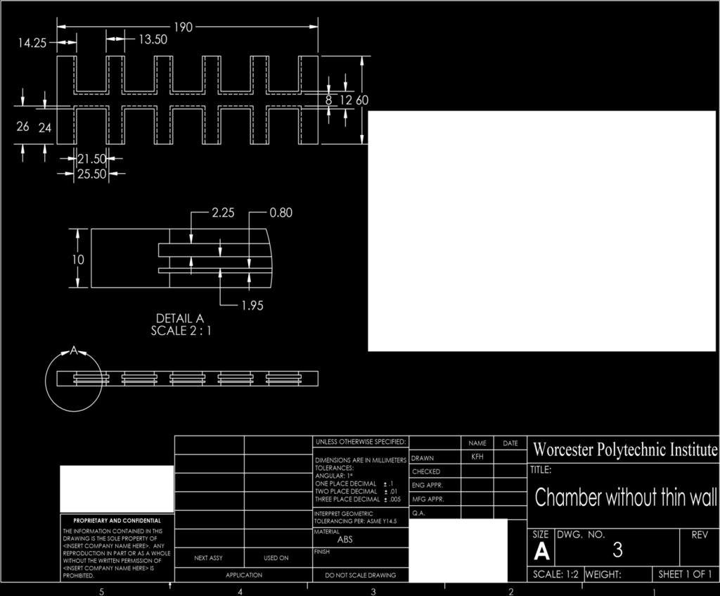
65 56
66 PROPRIETARY AND THE INFORMATION CONTAINED IN DRAWING IS THE SOLE PROPERTY <INSERT COMPANY NAME HERE>. REPRODUCTION IN PART OR EAS A WITHOUT THE WRITTEN NEXT <INSERT COMPANY NAME PROHIBITE APPLCATIO USED UNLESS OTHERWISE DIMENSIONS ARE IN TOLERANCES ANGULAR: ONE PLACE DECIMAL TWO PLACE DECIMAL THREE PLACE DECIMAL INTERPRET Q.A TOLERANCING PER: ASME COMMENTS MATERIA FINIS AB DO NOT SCALE 4 DRAW CHECKE ENG MFG NAM KF DAT Worcester Polytechnic TITLE Mask SIZ DWG. RE A SCALE: WEIGHT: SHEET 1 OF

67 58

68 59

69 60
70 61 Appendix B: Alternative Mask Designs All diameters = 500 microns (0.50 mm) Mask_5 holes cross X 4 distances Distances between outer holes to center, adjacent Top left = 250 microns (0.25 mm), 560 microns (0.56 mm) Top right = 500 microns (0.50 mm), 910 microns (0.91 mm) Bottom right = 750 microns (0.75 mm), 1270 microns (1.27 mm) Bottom left = 1000 microns (1 mm), 1620 microns (1.62 mm) Shortest distance between separate designs (between bottom left and right): 3.82 mm Shortest distance to edge of mask: 7.36 mm
, 680 microns (0.68 mm) Bottom right = 750 microns (0.75 mm), 970 microns (0.97 mm) Bottom left = 1000 microns (1 mm), 1260 microns (1.")
71 62 Mask_6 holes pentagon X 4 distances All diameters = 500 microns Distances between outer holes to center, adjacent Top left = 250 microns (0.25 mm), 380 microns (0.38 mm) Top right = 500 microns (0.50 mm), 680 microns (0.68 mm) Bottom right = 750 microns (0.75 mm), 970 microns (0.97 mm) Bottom left = 1000 microns (1 mm), 1260 microns (1.26 mm) Shortest distance between separate designs (between bottom left and right): 3.96 mm Shortest distance to edge of mask: 7.44 mm (bottom left to left edge)
72 63 Mask 7 holes hexagon X 4 distances All diameters = 500 microns Distances between outer holes to center, adjacent* Top left = 250 microns (0.25 mm) Top right = 500 microns (0.50 mm) Bottom right = 750 microns (0.75 mm) Bottom left = 1000 microns (1 mm) *Distance between all holes in pattern the same Shortest distance between separate designs (between bottom left and right): 4.19 mm Shortest distance to edge of mask: 7.36 mm (bottom left to bottom edge)
73 64 Mask_lines 500 microns thick_ varying distances microns Slots = 500 microns wide (0.50 mm) constant Distance between slots varies from 100 microns (0.100 mm) at bottom by increments of 100 microns up to 1000 microns (1 mm) at the top
 at bottom by increments of 100 microns up to 1000 microns (1 mm) at the top Distance between slots = 500 microns (0.")
74 65 Mask_lines varying microns thick_500 micron distances Thickness of slots vary from 100 microns (0.100 mm) at bottom by increments of 100 microns up to 1000 microns (1 mm) at the top Distance between slots = 500 microns (0.50 mm) constant
Frequently Asked Questions (FAQ)
") Frequently Asked Questions (FAQ) Matrigen Softwell Hydrogels Version 1.0 Contents General Questions... 3 Cell Culture and Experimental Questions... 6 Quality Control Technical Questions... 8 SoftTrac Products...
Frequently Asked Questions (FAQ) Matrigen Softwell Hydrogels Version 1.0 Contents General Questions... 3 Cell Culture and Experimental Questions... 6 Quality Control Technical Questions... 8 SoftTrac Products...
Hydrogel Viscoelastic Properties Pertaining to Cell Phenotype
 Washington University in St. Louis Washington University Open Scholarship Mechanical Engineering and Materials Science Independent Study Mechanical Engineering & Materials Science 9-12-2017 Hydrogel Viscoelastic
Electron Microscopy Sciences
 Electron Microscopy Sciences INSTRUCTIONAL MANUAL CAT. 64820, 64821 & 64822 Nanopatterned Cell Cultureware P.O. Box 550 s1560 Industry Road s Hatfield PA 19440 1 Terms Release of Liability This document
TractionsForAll. v1.0. September 1 st, Created by Aleksandar Marinković, Sc.D. & Daniel Tschumperlin, Ph.D.
 TractionsForAll v1.0 September 1 st, 2013 TractionsForAll v1.0 is freely distributed program that calculates tractions exerted by an adherent cell on the soft hydrogel substrate underneath. It is created
FORMLABS WHITE PAPER: A Guide to Post-Curing Formlabs Resins. March 2018 formlabs.com
 FORMLABS WHITE PAPER: A Guide to Post-Curing Formlabs Resins March 218 formlabs.com Table of Contents Abstract 3 Methodology 4 Introduction 5 Recommended Cure Settings: Clear. 6 Recommended Cure Settings:
FORMLABS WHITE PAPER: A Guide to Post-Curing Formlabs Resins. March 2018 formlabs.com
 FORMLABS WHITE PAPER: A Guide to Post-Curing Formlabs Resins March 218 formlabs.com Table of Contents Abstract 3 Methodology 4 Introduction 5 Recommended Cure Settings: Clear. 6 Recommended Cure Settings:
Application Note #124 VITA: Quantitative Nanoscale Characterization and Unambiguous Material Identification for Polymers
 Local thermal analysis identifies polymer AFM image of polymer blend Application Note #124 VITA: Quantitative Nanoscale Characterization and Unambiguous Material Identification for Polymers VITA module
Soft Fabrication and Polymers
 Introduction to BioMEMS & Medical Microdevices Soft Fabrication and Polymers Companion lecture to the textbook: Fundamentals of BioMEMS and Medical Microdevices, by Prof., http://saliterman.umn.edu/ R012408
3D Hydrogel System with Continuous Stiffness Gradient
 WORCESTER POLYTECHNIC INSTITUTE 3D Hydrogel System with Continuous Stiffness Gradient Christopher Gorgone, Claire Hambright, Lindsay Hock, and Melanie Wiater Advisors: Professor Ambady and Professor Wen
Methods in Bioengineering: 3D Tissue Engineering
 Methods in Bioengineering: 3D Tissue Engineering Berthiaume, Francois ISBN-13: 9781596934580 Table of Contents Preface Chapter 1. Chemical Modification of Porous Scaffolds Using Plasma Polymers 1.1. Introduction
Polymer-based Microfabrication
 Polymer-based Microfabrication PDMS SU-8 PMMA Hydrogel 1 Soft Lithography Developed by Whitesides, et. al A set of techniques for microfabrication based on the use of lithography, soft substrate materials
Lab Module 7: Cell Adhesion
 Lab Module 7: Cell Adhesion Tissues are made of cells and materials secreted by cells that occupy the spaces between the individual cells. This material outside of cells is called the Extracellular Matrix
The Effects of Scaffold Rigidity on Retinal Pigment Epithelial Cells. Corina White Symposium on Biomaterials Science 24 October 2016
 The Effects of Scaffold Rigidity on Retinal Pigment Epithelial Cells Corina White Symposium on Biomaterials Science 24 October 2016 Background Physiology The retina is the light-responsive tissue layer
Impact of Zinc Oxide on the UV Absorbance and Mechanical Properties of UV Cured Films
 Impact of Zinc Oxide on the UV Absorbance and Mechanical Properties of UV Cured Films R. K. SONI, MEENU TEOTIA* Department of Chemistry C.C.S, University, Meerut Ultraviolet radiation [UVR] UVR is divided
MECHANOBIOLOGY LAB MODULE
 MECHANOBIOLOGY LAB MODULE (MechB): Response of Patterned Fibroblast Cytoskeleton to Substrate Stiffness 1: Hydrogel Preparation Location: 3110 Digital Computing Laboratory (DCL) Lead Instructor: Andrew
The effectively utilization of oxygen in the process of. photopolymerization
 The effectively utilization of oxygen in the process of photopolymerization Ya Wu, Jun Nie Beijing University of Chemical Technology, Beijing 100029 Abstract: Oxygen has long been considered to be unfavorable
VitroGel ready-to-use tunable hydrogel for 3D cell culture and beyond
 VitroGel ready-to-use tunable hydrogel for 3D cell culture and beyond Cat No: TWG001 VItroGel 3D (10 ml high concentration) Cat No: TWG002 VitroGel 3D-RGD (10 ml high concentration) Handbook Rev. June
UV15: For Fabrication of Polymer Optical Waveguides
 CASE STUDY UV15: For Fabrication of Polymer Optical Waveguides Master Bond Inc. 154 Hobart Street, Hackensack, NJ 07601 USA Phone +1.201.343.8983 Fax +1.201.343.2132 main@masterbond.com CASE STUDY UV15:
1. Methacrylated poly(lactic acid) functionalized poly(ethylene glycol) (PEG) 2. Methacrylated sebacic acid
 functionalized poly(ethylene glycol) (PEG) 2. Methacrylated sebacic acid") LAB MODULE 2: Materials Degradation Surface vs. Bulk In this lab students will investigate how polymeric chemical structure can be used to control the degradation properties of the crosslinked network.
LAB MODULE 2: Materials Degradation Surface vs. Bulk In this lab students will investigate how polymeric chemical structure can be used to control the degradation properties of the crosslinked network.
Polymeric hydrogels are of special importance in polymeric biomaterials because of
 POLYMERIC HYDROGELS Polymeric hydrogels are of special importance in polymeric biomaterials because of their favorable biocompatibility. Hydrogels are cross-linked macromolecular networks formed by hydrophilic
Building HDI Structures using Thin Films and Low Temperature Sintering Paste
 Building HDI Structures using Thin Films and Low Temperature Sintering Paste Catherine Shearer, James Haley and Chris Hunrath Ormet Circuits Inc. - Integral Technology California, USA chunrath@integral-hdi.com
Advanced Polymers And Resists For Nanoimprint Lithography
 Q U A L I T Y A S S U R A N C E MICROSYSTEMS & NANOSYSTEMS SPECIAL REPORT Advanced Polymers And Resists For Nanoimprint Lithography Numerous polymer systems specifically designed for nanoimprint lithography
A REVIEW OF WATER RESISTANCE TEST METHODS FOR PRESSURE SENSITIVE ADHESIVES
 A REVIEW OF WATER RESISTANCE TEST METHODS FOR PRESSURE SENSITIVE ADHESIVES Laura J Donkus, Technical Service Scientist, The Dow Chemical Company, Collegeville, PA William B Griffith, PhD, Principal Scientist,
Growth factor delivery
 Growth factor delivery S. Swaminathan Director Centre for Nanotechnology & Advanced Biomaterials School of Chemical & Biotechnology SASTRA University Thanjavur 613 401 Tamil Nadu Joint Initiative of IITs
BFF1113 Engineering Materials DR. NOOR MAZNI ISMAIL FACULTY OF MANUFACTURING ENGINEERING
 BFF1113 Engineering Materials DR. NOOR MAZNI ISMAIL FACULTY OF MANUFACTURING ENGINEERING Course Guidelines: 1. Introduction to Engineering Materials 2. Bonding and Properties 3. Crystal Structures & Properties
STUDY OF SHAPE DEPOSITION MANUFACTURING
 STUDY OF SHAPE DEPOSITION MANUFACTURING 1 Ashish Bhorkade, 2 Chetan Bharambe, 3 Suraj Bhangale 4 Pankaj Patil 1,2,3 B.E.Scholar BVCOE&RI Nashik 4 Assistant Professor Mechanical Dept. BVCOE&RI Nashik ABSTRACT
Leveraging the Precision of Electroforming over Alternative Processes When Developing Nano-scale Structures
 VOLUME 4 - ELECTROFORMING Leveraging the Precision of over Alternative Processes When Developing Nano-scale Structures Electrical and mechanical component and subsystem designers generally have five techniques
NanoFabrication Systems DPN. Nanofabrication Systems. A complete line of instruments and tools for micro and nanopatterning applications
 DPN Nanofabrication Systems A complete line of instruments and tools for micro and nanopatterning applications DPN Nanofabrication Systems A complete line of instruments and tools for micro and nanopatterning
PREPARATION OF A MICROPATTERNED RIGID-SOFT COMPOSITE SUBSTRATE FOR PROBING CELLULAR RIGIDITY SENSING
 PREPARATION OF A MICROPATTERNED RIGID-SOFT COMPOSITE SUBSTRATE FOR PROBING CELLULAR RIGIDITY SENSING Materials 1. Coverslip (45x50mm #1; Fisher Scientific, Pittsburgh, PA) 2. Diamond-tip pen 3. Bunsen
Welcome to ENR116 Engineering Materials. This lecture summary is part of module 2, Material Properties.
 Welcome to ENR116 Engineering Materials. This lecture summary is part of module 2, Material Properties. 1 2 Mechanical properties. 3 The intended learning outcomes from this lecture summary are that you
A Novel Extrusion Microns Embossing Method of Polymer Film
 Modern Mechanical Engineering, 2012, 2, 35-40 http://dx.doi.org/10.4236/mme.2012.22005 Published Online May 2012 (http://www.scirp.org/journal/mme) A Novel Extrusion Microns Embossing Method of Polymer
Cell-Environment Interactions. Chieh-Chun Chen
 Cell-Environment Interactions Chieh-Chun Chen Part 1: Soft Lithography in Biology and Biochemistry Chieh-Chun Chen Outlines Introduction Key features of soft lithography Applications In microscopic biochemical
Microfluidic Devices that Capture Bacteria for Growth and Kill Analysis
 Microfluidic Devices that Capture Bacteria for Growth and Kill Analysis Michael J. Lochhead, PhD. Accelr8 Technology Corporation Denver, CO AVS Symposium Biomaterial Interfaces Microbe-Surface Interactions
Supplementary Figure S1. Swelling and mechanical properties as a function of the PS-b- PAA block copolymer composition. a, Swelling kinetics of PAA
 Supplementary Figure S1. Swelling and mechanical properties as a function of the PS-b- PAA block copolymer composition. a, Swelling kinetics of PAA homopolymer and PS-b-PAAs (4 mm disc with 1 mm thickness)
Regenerez : A Next-Generation Material for Functional Bioresorbable Coatings. by Carissa Smoot and Jeremy Harris, Ph.D, Secant Medical, Inc.
 Regenerez : A Next-Generation Material for Functional Bioresorbable Coatings by Carissa Smoot and Jeremy Harris, Ph.D, Secant Medical, Inc. Coatings consisting of natural and synthetic origin play an important
PLASTIC PIPE TERMS & DEFINITIONS
 PLASTIC PIPE TERMS & DEFINITIONS Every product has certain terms and definitions that are unique to that particular product. Listed below are some of the more common terms and definitions that relate to
Corning Microplates for Microscopy and High Content Imaging. Improve results with microplates for high resolution cell imaging
 Corning Microplates for Microscopy and High Content Imaging Improve results with microplates for high resolution cell imaging High Performance for Cell-based Assays Within the drug discovery process, high
Femtosecond micromachining in polymers
 Femtosecond micromachining in polymers Prof. Dr Cleber R. Mendonca Daniel S. Corrêa Prakriti Tayalia Dr. Tobias Voss Dr. Tommaso Baldacchini Prof. Dr. Eric Mazur fs-micromachining focus laser beam inside
Cells Culture Techniques Marta Czernik
 Cells Culture Techniques 13.03.2018 Marta Czernik Why we need the cell/tissue culture Research To overcome problems in studying cellular behaviour such as: - confounding effects of the surrounding tissues
Design of scaffolds with computer assistance
 Modelling in Medicine and Biology VII 157 Design of scaffolds with computer assistance H. A. Almeida 1, P. J. Bártolo 1 & J. C. Ferreira 2 1 Centre for Rapid and Sustainable Product Development CDRsp,
Modeling poly(ethylene glycol) Diacrylate Hydrogels Synthesized by EosinY/TEA Visible Light Photopolymerization
 Diacrylate Hydrogels Synthesized by EosinY/TEA Visible Light Photopolymerization") Modeling poly(ethylene glycol) Diacrylate Hydrogels Synthesized by EosinY/TEA Visible Light Photopolymerization Chu-Yi Lee, Georgia Papavasiliou, Omar Khalil and Fouad Teymour Department of Biomedical
Modeling poly(ethylene glycol) Diacrylate Hydrogels Synthesized by EosinY/TEA Visible Light Photopolymerization Chu-Yi Lee, Georgia Papavasiliou, Omar Khalil and Fouad Teymour Department of Biomedical
Analysis of cytoskeletal features in dried and living cells and slow dynamic experiments using Atomic Force Microscopy
 Analysis of cytoskeletal features in dried and living cells and slow dynamic experiments using Atomic Force Microscopy Author Watson, Gregory, Watson, Jolanta Published 008 Journal Title Journal of Physics:
Break the 3D barrier CORNING 3D CELL CULTURE
 Break the 3D barrier VESSELS SURFACES MEDIA CORNING 3D CELL CULTURE Get there fast with 3D cell culture. Whether you re just getting started in 3D cell culture, looking for proven ways to scale up, or
AN INEXPENSIVE TECHNIQUE TO FABRICATE HYBRID GLASS/PLASTIC OPTICAL FIBER SENSORS FOR STRUCTURAL HEALTH MONITORING
 4th International Conference on Earthquake Engineering Taipei, Taiwan October 1-13, 006 Paper No. 93 AN INEXPENSIVE TECHNIQUE TO FABRICATE HYBRID GLASS/PLASTIC OPTICAL FIBER SENSORS FOR STRUCTURAL HEALTH
High and Matched Refractive Index Liquid Adhesives for Optical Device Assembly
 As originally published in the SMTA Proceedings High and Matched Refractive Index Liquid Adhesives for Optical Device Assembly Taro Kenmochi Kyoritsu Chemical Chiyodaku, Tokyo, Japan Abstract There is
Low frequency magnetic shielding: Nanocrystalline coating vs. ferromagnetic foils.
 Low frequency magnetic shielding: Nanocrystalline coating vs. ferromagnetic foils. Nanovate -EM is an innovative direct coating technique proven to be a value-add alternative to conventional foils. Magnetic
Producing Metal Parts
 Producing Metal Parts CNC vs. Additive Manufacturing www.3dhubs.com METAL KIT 2 Introduction This Kit discusses how to select the right manufacturing process for metal parts by comparing CNC and Additive
Photolithography I ( Part 2 )
") 1 Photolithography I ( Part 2 ) Chapter 13 : Semiconductor Manufacturing Technology by M. Quirk & J. Serda Bjørn-Ove Fimland, Department of Electronics and Telecommunication, Norwegian University of Science
1 Photolithography I ( Part 2 ) Chapter 13 : Semiconductor Manufacturing Technology by M. Quirk & J. Serda Bjørn-Ove Fimland, Department of Electronics and Telecommunication, Norwegian University of Science
MICROFLUIDIC GAS DIFFUSION PLATFORM
 MICROFLUIDIC GAS DIFFUSION PLATFORM Bradley Wendorff Team Leader Drew Birrenkott Communicator Caleb Durante BWIG Jared Ness BSAC Professor Brenda Ogle, Ph.D. Client Professor Tracy Puccinelli, Ph.D. -
PROTEINS. *Adapted from Biotechnology: Science for the New Millennium by Ellyn Daugherty.
 PROTEINS Most biotech products have something to do with proteins either containing amino acids or entire proteins. To manufacture protein products, researchers must understand protein structure and function.
SET PROJECT STRUCTURAL ANALYSIS OF A TROUGH MODULE STRUCTURE, IN OPERATION AND EMERGENCY Luca Massidda
 SET PROJECT STRUCTURAL ANALYSIS OF A TROUGH MODULE STRUCTURE, IN OPERATION AND EMERGENCY Luca Massidda Table of Contents Introduction... 2 Finite element analysis... 3 Model description... 3 Mirrors...
Microfluidic for Testing Mechanical Properties of Cancer Cells
 Kaleidoscope Volume 11 Article 82 July 2014 Microfluidic for Testing Mechanical Properties of Cancer Cells Adrianne Shearer Follow this and additional works at: https://uknowledge.uky.edu/kaleidoscope
Properties of Dental Materials
 Properties of Dental Materials Importance of Studying Properties of Materials Materials used to replace teeth or parts of teeth must withstand oral environment and forces of mastication Materials must
Hydrogels: There is always room for Jello
 Hydrogels: There is always room for Jello Soft-solids and the evolution of medical device design Gavin Braithwaite, 56 Roland Street, Suite 310 Boston, MA 02129 Cambridge Polymer Group, Inc. Testing, Consultation,
Attenuated Total Reflectance (ATR)
") Technical Note FT-IR Spectroscopy Attenuated Total Reflectance (ATR) Key Features: Faster sampling Excellent for thick, continuous solids and liquids Saves sample preparation High quality spectral databases
Technical Note FT-IR Spectroscopy Attenuated Total Reflectance (ATR) Key Features: Faster sampling Excellent for thick, continuous solids and liquids Saves sample preparation High quality spectral databases
FORMLABS WHITE PAPER: How Mechanical Properties of Stereolithography 3D Prints are Affected by UV Curing. By Zachary Zguris, PhD formlabs.
 FORMLABS WHITE PAPER: How Mechanical Properties of Stereolithography 3D Prints are Affected by UV Curing By Zachary Zguris, PhD formlabs.com ABSTRACT The post-cure of parts printed with Formlabs resins
Characterization of Physical Properties of Roadware Clear Repair Product
 Characterization of Physical Properties of Roadware Clear Repair Product November 5, 2009 Prof. David A. Lange University of Illinois at Urbana-Champaign Introduction Roadware MatchCrete Clear (MCC) is
SUPPLEMENTAL INFORMATION: 1. Supplemental methods 2. Supplemental figure legends 3. Supplemental figures
 Supplementary Material (ESI) for Lab on a Chip This journal is The Royal Society of Chemistry 2008 A microfluidics-based turning assay reveals complex growth cone responses to integrated gradients of substrate-bound
University of Michigan
 University of Michigan Department of Mechanical Engineering Low-cost Non-invasive Diagnosis of Malaria Infected Red Blood Cells Han Yu Undergraduate Student Department of Electrical Engineering and Computer
If you were sick, say with cancer, would you not want a drug that has a way
 Stith 1 If you were sick, say with cancer, would you not want a drug that has a way of specifically targeting the cancer sell then releasing the medicine without harming the healthy cells? Of course you
Artificial blood vessels
 Artificial blood vessels S. Swaminathan Director Centre for Nanotechnology & Advanced Biomaterials School of Chemical & Biotechnology SASTRA University Thanjavur 613 401 Tamil Nadu Joint Initiative of
Illuminating Innovations
 Illuminating Innovations TM Silicone Solutions for LED Packaging Emir Debastiani Application Engineer Dow Corning Brazil Email: emir.debastiani@dowcorning.com Table of Contents Dow Corning Introduction
CHAPTER 3: DESIGN VALUES FOR MATERIALS
 CHAPTER 3: DESIGN VALUES FOR MATERIALS 3.1 GENERAL (1) The quality of concrete and reinforcing materials are expressed, in addition to compressive strength and tensile strength, in terms of material characteristics
Coatings. Ion Assisted Deposition (IAD) process Advance Plasma Source (APS) plasma-ion assisted Deposition. Coatings on Optical Fibers
 process Advance Plasma Source (APS) plasma-ion assisted Deposition. Coatings on Optical Fibers") Anti-Reflection Custom Ion Assisted Deposition (IAD) process Advance Plasma Source (APS) plasma-ion assisted Deposition Anti-Reflection on Optical Fibers OptoSigma supplies a wide selection of optical
Anti-Reflection Custom Ion Assisted Deposition (IAD) process Advance Plasma Source (APS) plasma-ion assisted Deposition Anti-Reflection on Optical Fibers OptoSigma supplies a wide selection of optical
EDGE CHIPPING RESISTANCE USING MACROINDENTATION TESTING
 EDGE CHIPPING RESISTANCE USING MACROINDENTATION TESTING Prepared by Ali Mansouri 6 Morgan, Ste156, Irvine CA 92618 P: 949.461.9292 F: 949.461.9232 nanovea.com Today's standard for tomorrow's materials.
Seevix s SVXgro: A Spidersilk Scaffold for Tissue Engineering
 Seevix s gro: A Spidersilk Scaffold for Tissue Engineering Spider dragline silk exhibits extraordinary mechanical properties that combine strength with elasticity, resulting in a toughness exceeding that
Material HDT Continuous Use Temp. Radal (Polyphenylsulfone) 400 F 300 F
 400 F 300 F") Material Selection* Failures arising from hasty material selection are not uncommon in plastics or any other industry. In an application that demands high-impact resistance, a high-impact material must
Material Selection* Failures arising from hasty material selection are not uncommon in plastics or any other industry. In an application that demands high-impact resistance, a high-impact material must
YIELD & TENSILE STRENGTH OF STEEL & ALUMINIUM USING MICROINDENTATION
 YIELD & TENSILE STRENGTH OF STEEL & ALUMINIUM USING MICROINDENTATION Prepared by Duanjie Li, PhD & Pierre Leroux 6 Morgan, Ste156, Irvine CA 9618 P: 949.461.99 F: 949.461.93 nanovea.com Today's standard
BY JACK AND TABO FIBER REINFORCED COMPOSITE
 BY JACK AND TABO FIBER REINFORCED COMPOSITE DEFINITION: FIBRE-REINFORCED PLASTIC (FRP) (ALSO FIBRE- REINFORCED POLYMER) IS A COMPOSITE MATERIAL MADE OF A POLYMER MATRIX REINFORCED WITH FIBRES. THE FIBRES
Methods: General Techniques OEST 740
 Methods: General Techniques OEST 740 042108 Outline Introduction Techniques for Growth Flow and steady state methods Microscopici Adherence Formation Physiology and Structure Chemical analysis Quantitative
BLOCK COPOLYMER PHOTONIC GEL FOR DETECTING INTERFACIAL SEPARATION
 BLOCK COPOLYMER PHOTONIC GEL FOR DETECTING INTERFACIAL SEPARATION Edwin P. Chan, Materials Research Engineer, National Institute of Standards and Technology, Gaithersburg, MD Introduction Mechanochromism,
Supplementary Information for
 Supplementary Information for An ultra-sensitive resistive pressure sensor based on hollow-sphere microstructure induced elasticity in conducting polymer film Lijia Pan, 1,2 Alex Chortos, 3 Guihua Yu,
3D Transfection System
 3D Transfection System Why 3D Technology? Introduction to Three Dimensional (3D) Cell Culture The goal of three-dimensional (3D) cell culture is to eliminate the stress and artificial responses cells experience
Cyclic Stress-Strain Curve for Low Cycle Fatigue Design and Development of Small Specimen Technology
 1 PD/P8-2 Cyclic Stress-Strain Curve for Low Cycle Fatigue Design and Development of Small Specimen Technology A. Nishimura 1, S. Nogami 2, E. Wakai 3 1 National Institute for Fusion Science (NIFS), Toki,
NanoTA2 Sub-100nm Local Thermal Imaging and Analysis
 Anasys Instruments introduces the second generation of its award winning nano thermal analysis product, the NanoTA2. This system extends the capabilities of the nano-ta system by the addition of local
Development of Elastic Polylactic Acid Material Using Electron Beam Radiation
 ELECTRONICS Development of Elastic Polylactic Acid Material Using Electron Beam Radiation Shinichi KANAZAWA Sumitomo Electric Fine Polymer has developed a technology for fabricating a brand new elastic
Sélection Internationale Ens Ulm 2012, Cell Biology
 Sélection Internationale Ens Ulm 2012, Cell Biology Please read the whole subject before starting. Questions 1-8 and 12-14 are general biology questions. In questions 9, 10, 11 and15, we ask you to interpret
Chapter 8. Comparison of static vs dynamic culture
 Chapter 8 Comparison of static vs dynamic culture 8.1. Literature Review Articular cartilage is a load-bearing connective tissue in which its functions not only transmitting the compressive joint loads
Design and fabrication of functionally graded components by selective laser melting. C. N. Sun*#, S. Y. Choy*+, K. F. Leong*+, J.
 Solid Freeform Fabrication 216: Proceedings of the 26th 27th Annual International Solid Freeform Fabrication Symposium An Additive Manufacturing Conference Design and fabrication of functionally graded
Freshman/Sophomore Junior Senior
 Freshman/Sophomore Junior Senior Course Recommendations Mathematics (6 courses) MA 1021 MA 1024 (Calculus I) (Calculus IV) MA 1022 MA 2051 (Calculus II) (Differential Equations) MA 1023 MA 2611 (Calculus
Part IA Paper 2: Structures and Materials MATERIALS Examples Paper 3 Stiffness-limited Design; Plastic Deformation and Properties
 Engineering Part IA Paper 2: Structures and Materials MATERIALS FIRST YEAR Examples Paper 3 Stiffness-limited Design; Plastic Deformation and Properties Straightforward questions are marked with a Tripos
Controlled Release Drug Delivery from Hydrogels
 Controlled Release Drug Delivery from Hydrogels Teacher s Guide Keith Neeves CSIP Graduate Fellow Cornell University 1 Overview The objective of this project is to introduce students to the concepts of
SELF HEALING COATINGS FOR CORROSION CONTROL
 SELF HEALING COATINGS FOR CORROSION CONTROL Bryan E. Koene, Shi-Hau Own, Kristen Selde Luna Innovations, Incorporated. Blacksburg, VA 24060 USA Tel: 1-540-558-1699 Fax: 1-540-951-0760 koeneb@lunainnovations.com
Pittsburgh Tissue Engineering Initiative Annual Progress Report: 2010 Formula Grant
 Pittsburgh Tissue Engineering Initiative Annual Progress Report: 2010 Formula Grant Reporting Period July 1, 2011 December 31, 2011 Formula Grant Overview The Pittsburgh Tissue Engineering Initiative,
The research work highlights the development and evaluation of. bioavailability of drugs. The buccal route can bypass the first-pass
 212 9. Summary, conclusion and recommendation 9.1 Summary and conclusion The research work highlights the development and evaluation of novel transbuccal drug antagonist of Famotidine. route have a rapid
Low-Cost Bioreactor to Enable Microbe Productivity Optimization
 Low-Cost Bioreactor to Enable Microbe Productivity Optimization Design Team David Christianson, Elizabeth Duffy Bryan Keen, Andrew Mazzotta Jameson Stark Design Advisor Prof. Jeffrey Ruberti Email: j.ruberti@neu.edu
UV-curable Dielectrics
 UV-curable Dielectrics Metal conductors are in general coated with a dielectric coating for insulating the conductors. Such coatings require good insulating properties in a variety of environments. It
Introduction to Polymer-Dispersed Liquid Crystals
 Introduction to Polymer-Dispersed Liquid Crystals Polymer-dispersed liquid crystals (PDLCs) are a relatively new class of materials that hold promise for many applications ranging from switchable windows
Biomaterials. Third Edition
 Biomaterials Third Edition Joon Park R.S. Lakes Biomaterials An Introduction Third Edition Joon Park Biomedical and Mechanical Engineering University of Iowa Iowa City, IA 52242-1414 USA joon-park@uiowa.edu
Introduction: Standard Plastic Terminology Plastic Program Analysis and Development p. 1 Selecting the Design Team for Success p. 3 Using Checklists
 Preface p. xv Introduction: Standard Plastic Terminology p. xix Plastic Program Analysis and Development p. 1 Selecting the Design Team for Success p. 3 Using Checklists to Develop Product Requirements
Multiphoton lithography based 3D micro/nano printing Dr Qin Hu
 Multiphoton lithography based 3D micro/nano printing Dr Qin Hu EPSRC Centre for Innovative Manufacturing in Additive Manufacturing University of Nottingham Multiphoton lithography Also known as direct
Developing Formable Properties in Energy Curable Flexographic Inks
 Developing Formable Properties in Energy Curable Flexographic Inks Robert Kensicki, William Wolf Sartomer Americas Arkema Group 502 Thomas Jones Way Exton, PA 19341 Abstract This paper investigates technical
RADIATION STERILIZATION OF DEVICES AND SCAFFOLDS FOR TISSUE ENGINEERING. Celina I. Horak National Commission of Atomic Energy Argentina
 RADIATION STERILIZATION OF DEVICES AND SCAFFOLDS FOR TISSUE ENGINEERING Celina I. Horak National Commission of Atomic Energy Argentina Effectively sterilize The selected method for sterilization of scaffolds
Biomedical Applications of Molecular Spectroscopy
 Biomedical Applications of Molecular Spectroscopy Mike Kayat B&W Tek, Inc 19 Shea Way Newark, DE 19713 United States of America +1 302 368 7824 mikek@bwtek.com 1 Overview Molecular spectroscopy is a large
Cell Processing Workstation. In Situ Laser-Mediated Cell Purification and Processing
 LEAP Cell Processing Workstation Cell Processing Workstation In Situ Laser-Mediated Cell Purification and Processing Expanding the Capabilities of Cell Processing Consistent, High-Yield, High-Purity Processing
Overview of Immunohistochemistry
 Overview of Immunohistochemistry Immunohistochemistry (IHC) combines anatomical, immunological and biochemical techniques to identify discrete tissue components by the interaction of target antigens with
Bio MEMS Class -1 st week
 Bio MEMS Class -1 st week Jang, Jaesung Ref: Bashir ADDR Review paper, 2004. 1 Introduction Bio-MEMS: devices or systems, constructed using techniques inspired from micro/nano-scale fabrication, that are
Cell and Tissue Culture
 Cell and Tissue Culture S. Swaminathan Director Centre for Nanotechnology & Advanced Biomaterials School of Chemical & Biotechnology SASTRA University Thanjavur 613 401 Tamil Nadu Joint Initiative of IITs
Micro Fabrication : Soft Lithography
 Micro Fabrication : Soft Lithography Last Class: 1. Electrowetting on Dielectric (EWOD) 2. Setup in EWOD 3. Basic Manipulations : Mixing Splitting, Translation 4. Optoelectrowetting (OEW) Today s Contents:
CHAPTER 4 WATER ABSORPTION BEHAVIOR AND ACCELERATED AGING EFFECTS
 1 CHAPTER WATER ABSORPTION BEHAVIOR AND ACCELERATED AGING EFFECTS.1 INTRODUCTION The mechanical properties of the polymer matrix composites depend on the properties of their constituents and their interaction