A Composite Structural Steel and Prestressed Concrete Beam for Building Floor Systems
|
|
|
- Owen Woods
- 6 years ago
- Views:
Transcription

1 University of Nebraska - Lincoln DigitalCommons@University of Nebraska - Lincoln Architectural Engineering -- Dissertations and Student Research Architectural Engineering Spring A Composite Structural Steel and Prestressed Concrete Beam for Building Floor Systems Nathan dewit University of Nebraska-Lincoln, ndewit@mail.unomaha.edu Follow this and additional works at: Part of the Architectural Engineering Commons, Construction Engineering Commons, and the Other Engineering Commons dewit, Nathan, "A Composite Structural Steel and Prestressed Concrete Beam for Building Floor Systems" (2012). Architectural Engineering -- Dissertations and Student Research This Article is brought to you for free and open access by the Architectural Engineering at DigitalCommons@University of Nebraska - Lincoln. It has been accepted for inclusion in Architectural Engineering -- Dissertations and Student Research by an authorized administrator of DigitalCommons@University of Nebraska - Lincoln.
2 A COMPOSITE STRUCTURAL STEEL AND PRESTRESSED CONCRETE BEAM FOR BUILDING FLOOR SYSTEMS by Nathan J. dewit A THESIS Presented to the Faculty of The Graduate College at the University of Nebraska In Partial Fulfillment of Requirements For the Degree of Master of Science Major: Architectural Engineering Under the Supervision of Professor George Morcous Lincoln, Nebraska May, 2012
3 A COMPOSITE STRUCTURAL STEEL AND PRESTRESSED CONCRETE BEAM FOR BUILDING FLOOR SYSTEMS Adviser: George Morcous Nathan Jon dewit, M.S. University of Nebraska, 2012 Precast prestressed concrete beams, such as rectangular and inverted tee beam, currently used in residential and commercial buildings are deep, heavy, and limited to span-to-depth ratios of 15. The research proposes a composite structural steel and prestressed concrete beam that is shallow, light, easy to produce and erect, and able to achieve a span-to-depth ratio of 24. The proposed beam is designed to be used with precast columns, hollow-core planks, and a cast-in-place topping to create a momentresisting floor system that minimizes the need for shear walls. The goal of this system is to eliminate as many of the limitations of precast concrete buildings as possible while remaining economically competitive. The developed beams consists of one half of a standard steel W-section, embedded into the top of a shallow rectangular prestressed concrete bottom flange, to create a composite section that supports hollow-core planks. Cast-in-place concrete is then used to fill the voids between the hollow-cores and composite beam and provide a leveled topping. A typical commercial building was analyzed and designed using the proposed beam under normal loading conditions. This design example indicated that the proposed system is economical, shallower, lighter, and more resistant to lateral loads than conventional precast concrete floor systems.
4 Table of Contents Chapter 1 - Introduction Problem Statement Objectives Scope... 3 Chapter 2 Literature Review Cast-in-place systems Structural Steel Systems Precast Systems Proprietary & Emerging Systems Delta Beam Girder-slab Versa: T Beam Shallow Hollow-Core Floor System Patented Systems Chapter 3 System Overview System Development System Description Structural System Overview Production Erection & Construction Service Chapter 4 System Analysis & Design Design Criteria Gravity Loads Hollow-Core Design T-RECS Beam Design Precast Column Design Precast L-Beam Design Lateral Analysis Deflections Connection Design Moment Embed Connection Design Torsion Connection Design Chapter 5 Cost Estimate and Design Aids Design Aids Cost Estimate Chapter 6 Conclusions Bibliography Appendix A Section Properties B Pre-Composite Shear Design C WF Beam Analysis during CIP Topping Pour i
5 D Composite Shear Design E Flexural Strength (Positive Moment) F Flexural Strength (Negative Moment at Support) G ASCE7 05 MWFRS Wind Profile Calculation H Structure Weight for Seismic Design I ASCE7-05 Seismic Load Story Shear Calculation J Beam Deflections ii
6 List of Figures Figure 2.1 Construction of Deltabeam Floor System with Shoring (Peikko Group, 2012)... 1 Figure 2.2 Typical Girder-Slab Floor System (Girder-Slab Technologies, 2008)... 1 Figure 2.3 Diversakore Floor System (Diversakore, 2012)... 1 Figure 2.4 Shallow Hollow-Core Floor System (Tadros and Morcous, 2011)... 1 Figure 2.5 Column Capital System (Hanlon,1990)... 1 Figure 2.6 T Shaped Steel Cutting (Kim, 2011)... 1 Figure 2.7 Composite beam with T-Type Steel (Kim, 2011)... 1 Figure 2.8 Composite Beam with T-Steel (Kim, 2011)... 1 Figure 3.1 Effects of Increasing Compression Steel Area (A ps = 1.53 in 2 )... 1 Figure 3.2 Effects of Increasing Compression Steel Area (A ps = in 2 )... 1 Figure 3.3 Effects of Increasing Compression Steel Area (A ps = in 2 )... 1 Figure 3.4 Effects of Increasing Compression Steel Area (A ps = in 2 )... 1 Figure 3.5 Typical Beam Elevation... 1 Figure 3.6 Wide Flange Beam Manufacturing Process... 1 Figure 3.7 Typical Cross Section at A... 1 Figure 3.8 Typical Cross Section at B... 1 Figure 3.9 Column Embed Detail... 1 Figure 3.10 Typ. Column Connection... 1 Figure 3.11 Typical Column Connection... 1 Figure 3.12 Erect precast columns cast with corbels and embed plates... 1 Figure 3.13 Erect T-RECS beams and L spandrels... 1 Figure 3.14 Make connection to precast column and install torsion restraints... 1 Figure 3.15 Place hollow-core on one half of beam & feed rebar into hollow-core... 1 Figure 3.16 Place second bay of hollow-core & reposition rebar... 1 Figure 3.17 Position topping reinforcement over beams & around columns... 1 Figure 3.18 Pour CIP topping... 1 Figure 4.1 Typical Floor Plan... 1 Figure 4.2 Typical Building Section... 1 Figure 4.3 Composite Hollow-Core Section... 1 Figure 4.7 Stage 3 Loads at Service Life... 1 Figure 4.4 Stage 1 Loads at Release... 1 Figure 4.5 Stage 2 Loads During Erection... 1 Figure 4.6 Stage 2 Loads During CIP Pour... 1 Figure 4.8 Cross Section at A... 1 Figure 4.9 Cross Section at B... 1 Figure 4.10 T-RECS Beam Elevation with Reinforcement... 1 Figure 4.11 WF Beam Manufacturing Detail... 1 Figure 4.12 Stage 2 Uniform Dead Load... 1 Figure 4.13 Stage 2 Shear Diagram... 1 Figure 4.14 Stage 2 Moment Diagram... 1 Figure 4.15 Stage 2 Factored Load Diagram (Pre-Composite)... 1 ii
7 Figure 4.16 Stage 2 Factored Shear Diagram (Pre-Composite)... 1 Figure 4.17 Stage 2 Factored Moment Diagram (Pre-Composite)... 1 Figure 4.18 Stage 3 Factored Load Diagram (Post-Composite)... 1 Figure 4.19 Stage 3 Factored Shear Diagram (Post-Composite)... 1 Figure 4.20 Stage 3 Factored Moment Diagram (Post-Composite)... 1 Figure 4.21 Fully Composite Cross Section... 1 Figure 4.22 Full Composite Cross Section at Web Opening... 1 Figure 4.23 Typical Connection at Column Section... 1 Figure 4.24 Typical Connection at Interior Column... 1 Figure 4.25 Stage 3 Service Loads... 1 Figure 4.26 Stage 3 Service Load Shear Diagram... 1 Figure 4.27 Stage 3 Service Load Moment Diagram... 1 Figure 4.28 Stress Diagrams for Transformed Cross Section (8 ksi)... 1 Figure 4.29 Strain Diagrams for Transformed Cross Section (8 ksi)... 1 Figure 4.30 Interaction Diagram for Prestressed Concrete Column... 1 Figure 4.31 Interaction Diagram for Reinforced Concrete Column... 1 Figure 4.32 Service Level Story Forces for Each Moment Frame Due to Wind Loading 1 Figure 4.33 Service Level Story Forces for Each Moment Frame Due to Seismic Loading... 1 Figure 4.34 Ultimate Factored Loads for Each Moment Frame Due to Seismic Loading1 Figure 4.35 Ultimate Factored Moment Diagrams for Beams... 1 Figure 4.36 Ultimate Factored Moment Diagrams for Columns... 1 Figure 4.37 Deflections at Release... 1 Figure 4.38 Deflections During Construction... 1 Figure 4.39 Deflections for Service Loads... 1 Figure 4.40 Total Deflections... 1 Figure TR24-S12 Load Table... 1 Figure TR24-S14 Load Table... 1 Figure TR28-S18 Load Table... 1 Figure TR32-S22 Load Table... 1 iii
8 iv List of Tables Table Summary of Section Properties Table Stress Check at Release Table Flexure Analysis of Steel Beam Table Stress Check at Erection Table Strength Design of T-RECS Beam Table Stress Check at Service Life Table Interstory Drift Table T-RECS Section Properties Table 5.2 Cost Analysis of Comparable Steel System... 1 Table 5.3 Cost Analysis of Proposed System... 1
9 1 Chapter 1 - Introduction Problem Statement Many options are available to designers when developing the structural system of a building. The most common approaches are precast concrete, cast-in-place (CIP) concrete, or structural steel, each with its own distinct advantages and disadvantages. Typical drawbacks of a standard precast system include low span-to-depth ratios of floors as well as the need for shear walls to resist lateral loads. This means increased costs in the façade, mechanical electrical and plumbing (M/E/P) systems, and greater energy consumption for heating and cooling, due to increased floor-to-floor heights as well as a decrease in the versatility of the space. Prestressing can be utilized to improve the spanto-depth ratios of precast but it still underperforms when compared to steel. Steel systems will often utilize bar joists to support the floor structure; however, they too have rather low span-to-depth ratios. One of the major deficiencies of steel structures is that they have low fire-resistance characteristics and require the use of special partitions or fireproofing methods. Steel structures typically will employ frames to resist the applied lateral loads, which allow the architect much more flexibility over a shear wall system when designing the layout and functionality of the building. Additionally, steel is much lighter than concrete and this saves on erection costs. One of the primary concerns of cast-in-place systems is they usually require the use of formwork and shoring while curing, which results in increases in construction cost and duration over typical precast construction. Post-tensioning of CIP concrete allows for some of the shallowest floor systems but they are rather complex systems to construct. The ideal structural system
10 2 would eliminate the drawbacks of each of these traditional systems while retaining as many of the advantages of each as possible Objectives The primary objective of this project is to develop a shallow composite structural steel and prestressed concrete beam for residential and commercial construction. The beam being developed is designed to have the following features to address the shortcomings of existing floor beams: All exposed surfaces should be concrete to take advantage of its fire-resistance characteristics. Utilize both steel and prestressing strand to achieve a span-to-depth ratio of 24 or better which will help decrease the floor-to-floor heights as well as decrease the erection weight over standard precast components. Detail member connections as full moment resistant connections to reduce the positive moments, and resist lateral loads, while maintaining simplicity of the connection for construction. Use precast concrete components for as much of the building as possible to take advantage of its greater production quality, improved construction and erection time, and eliminate the need for formwork and shoring. Produce all structural components with standard materials and in a minimally complex manner so that the system can be commercially viable in as many markets as possible.
11 Scope The scope of this project is constrained purely to the development and theoretical evaluation of the proposed system. An analysis is conducted on all structural components for resisting both the gravity and lateral loads of a typical six-story office building in zones with low seismic activity. This evaluation includes the analysis, design, production methodology, construction sequencing, and detailing of all typical members and member connections. Full-scale testing should be done in the future to verify the assumptions and performance of the structural system presented.
12 4 Chapter 2 Literature Review The literature review for this report focuses on current structural systems commonly available to designers for residential and commercial buildings, which is the target application for the proposed system. Currently, the most common systems are cast-inplace, structural steel with steel joist or wide flange beams, precast concrete, as well as several proprietary systems. The scope of the proprietary systems for this literature review is limited to composite structural systems. The remainder of this chapter briefly describes the attributes of each of these systems. 2.1 Cast-in-place systems CIP systems have many inherent advantages. It is an extremely versatile material because its shape is directed by formwork erected on site. The formwork can be configured into almost any shape or dimension desired. Another advantage of CIP concrete is the continuity of the system, which allows for the implementation of frames as the lateral load resisting system. This gives the architect significant versatility in the floor plan of the space by allowing for greater flexibility in placement of walls. Columns, beams, and floors are cast monolithically and therefore; do not require connections between members as most other structural systems do. The natural properties of concrete make it a very durable material, allowing it to withstand extreme weather and last a long time. It also has significant advantages over steel when it comes to fire protection, thermal performance, and acoustic characteristics. A typical span-todepth ratio of a CIP beam is typically around 15 to ensure that the beam conform to the
13 5 requirements for live load deflections. For the slab, a conservative estimate is around 30 but this can vary greatly based on the floor being a one or two-way system and whether or not it is constructed as a continuous floor over the beam supports. For a 30 x 30, bay this translates to beams with a depth of 24 and an approximate slab depth of These values can be significantly improved by implementing post-tensioning. However; this means added cost due to the need for specialty contractors to perform the post-tensioning, as the systems can be rather complex and have very strict construction tolerances. The main drawback of CIP systems is the cost and time required for formwork construction, as this is very labor intensive. The formwork may also require shoring to reach longer span lengths, thereby adding additional cost to the project. The subject of quality control is more of a concern with CIP concrete systems too, with issues such as material testing for strength and slump needing to be conducted on site. Weather also poses challenges to CIP systems; common concretes require certain temperatures for curing and typically cannot be poured during rain. 2.2 Structural Steel Systems Structural steel is a very common solution to many commercial applications as well. Steel is an attractive option due to the material s high strength and relatively lower weight compared to concrete. Similar to CIP structures, steel allows for great versatility to the floor plan due to its ability to utilize beam-column frames to resist the lateral loads. Steel joists can also attain very large span lengths. Typically, steel structures will utilize a 2 steel deck with an additional 2 CIP floor. The floor can be either composite or
14 6 non-composite with the joists. Steel joist, spaced at approximately 6 on center, support the floor and these are usually supported by either wide flange beams or steel joists spanning between columns. A 30 x 30 bay typically requires steel joist girders around 30 deep. Accounting for the 5 depth of the floor joist s bearing height and an additional 4 for the floor, the total depth is around 39. However, the joists allow mechanical chases to run between the webs in the joists, which enables finish ceiling to come up near the bottom of the joists. A standard wide flange (WF) section for this type of system would be a WF18x106. The drawbacks of steel include high material costs, a lead-time on the ordering of materials, and decreased fire and corrosion resistance compared to concrete, unless treated and maintained with fireproofing materials. 2.3 Precast Systems Precast concrete is another attractive solution to builders for a variety of reasons. It allows for much greater production quality and consistency of concrete over its CIP counterpart. Precast concrete also does not have the weather concerns that a CIP system is susceptible to because it is typically produced indoors away from the elements. Precast concrete also provides significant benefits in the schedule and cost of a project due to its fast erection time and the repetitious nature of the components. It does not require the setting up of formwork, pouring concrete, and then curing of the concrete to achieve an acceptable level of strength. To maximize these benefits, many precast elements have been standardized by the industry; these include solid slabs, hollow-core slabs, double tees, inverted tees, and L-beams. The cost effectiveness of precast is lost, however, if unusual sizes and shapes must be utilized and sometimes production
15 7 capabilities of the plant will not allow for these types of pieces to be produced. Most precast structures will typically consist of hollow-core slabs supported by inverted tee (IT) beams that are then supported by precast columns with corbels. Precast can also be effectively used in conjunction with other structural elements such as steel beams and CIP toppings. The topping can be either non-structural or composite with the precast to give additional strength and continuity to the system. Prestressing also helps to improve the performance of precast concrete. A typical precast prestressed concrete system with 30 spans will have 6 hollow-core planks with a 2 topping supported by 28 IT beams for a total depth of around 30. However, unlike joists, mechanical equipment cannot pass through the IT beams so additional depth is needed for drop ceilings to allow the mechanical equipment to pass below the IT beams. Precast concrete typically requires more planning in the preliminary design because pieces are produced off-site. Issues such as connections and penetrations must be coordinated with other trades prior to production. Precast concrete must be transported to the job site, and any cost savings can be lost if transporting pieces long distances. Concrete is significantly heavier than steel and this creates a need for cranes and/or lifting equipment with higher lifting capacities. Once constructed, however, the concrete provides great fire protection, durability, deflection performance, and vibration characteristics. 2.4 Proprietary & Emerging Systems There are a variety of systems available that could be considered non-standard types of structural systems. The scope here will be limited to systems that are currently available, for residential and commercial applications, and are composite in nature.

16 Delta Beam The Delta Beam system is a rapidly emerging shallow floor system produced by Peikko Group which implements a composite beam composed of a hollow steel member formed with steel plates into a trapezoidal shape. This steel beam supports a hollow-core, thin shell slabs, or CIP floor system. The beam is then integrated with a CIP topping which fills all of the voids in the steel beam. This system can span approximately 30 at a depth of around 18 with a 2 topping for a total depth of approximately 20 inches. This is shallower than precast concrete systems; however, the Delta Beam requires shoring of each span and this adds costs in time and material to the system. Materials must be purchased for the shoring and floor-to-floor construction times are slowed while waiting for the CIP concrete to obtain adequate strength. The construction of a project using this system is shown in Figure 2.1. Figure 2.1 Construction of Deltabeam Floor System with Shoring (Peikko Group, 2012)

17 9 Peikko s web site claims the system has a fire rating of R120 which is a two-hour fire rating. Higher ratings can be achieved with the delta beam but additional fireproofing steps must be taken. Another drawback of this system is that both the columns and beams cannot be continuous simultaneously which creates discontinuities for moment transfer in either the beams or columns Girder-slab Girder-Slab Technologies has developed the Girder-Slab System which is a steel and precast composite structural system. It utilizes precast slabs with an integral steel beam to form a composite beam. Extended bottom flanges of the steel beam support the precast planks. Figure 2.2 shows what the typical floor system looks like. Figure 2.2 Typical Girder-Slab Floor System (Girder-Slab Technologies, 2008) The system is only 8-10 deep, dependent on if a 2 topping is utilized, and provides a flat soffit which allows for mechanical equipment to be easily run without adding more depth to plenum space of the system. An effective bay size for this type of system is a 20 x 28 with the girders spanning the 20 dimension. This is lower than would typically

18 10 be expected for office applications and limits the space as well as increases the number of columns required. Due to its shorter span lengths, this product is marketed primarily for residential applications Versa: T Beam Diversakore has developed a system similar to the Delta Beam with a different take on the steel shape utilized to create the composite girder. The steel is formed into a channel with studs anchored to the bottom to help the concrete achieve composite action with the steel. The assembly is reinforced with longitudinal bars and stirrups. The Versa: T Beam can be used in conjunction with 8 hollow-core planks, hollow-core with a CIP topping (as shown in Figure 2.3), or a steel deck. This method gives it an advantage over traditional CIP systems because the floor system and steel beam act as the formwork for the CIP concrete. The primary disadvantage of this system is again the need to shore the steel members during construction. This system also only has a two-hour fire rating and additional measures must be taken if greater fire-resistance is required. Figure 2.3 Diversakore Floor System (Diversakore, 2012)

19 Shallow Hollow-Core Floor System Tested and developed by the University of Nebraska, the Shallow Hollow-Core Floor System is a prestressed concrete system that utilizes precast prestressed IT beams with hollow-core and a CIP topping. This system achieves a better span-to-depth ratio by making the IT beam wider instead of deeper and making all the components continuous throughout the structure. A cross section of the beam can be seen in Figure 2.4. The system achieves continuity through the column by having a key-way for CIP concrete and moment reinforcing. For bay sizes of 32 x 34, the system was able to have a beam depth of 16. Because the system is completely composed of concrete, it can easily achieve at least a two-hour fire rating, but it also causes the members to be much heavier than steel members. This creates the need for larger cranes with greater capacities. Figure 2.4 Shallow Hollow-Core Floor System (Tadros and Morcous, 2011) Patented Systems Many patents exist for a wide variety of composite beams and slab systems. Hanlon developed a precast system (US patent 2008/ ) where columns are cast integrally with large capitals at the floor level. The largest system described allows for spans up
20 12 to 50 with a capital depth of 24 and width of 12 x 12. The capitals support precast planks which span from capital to capital through the use of bearing connections across the precast joint. All components are preferably prestressed and reinforced with additional mild steel. Figure 2.5 shows a diagram of the systems. 10- Precast Column 20- Column Capital 30- Concrete Beam Slabs 40- Concrete Joist Slabs 70- Slab Hangers Figure 2.5 Column Capital System (Hanlon,1990) Kim et al. recently developed a system which was published and patented late in 2011 (US 2011/ ) after this project had been undertaken. It utilizes some of the same concepts to be presented in this project. The girder is composed of a steel WF beam cut in half with a saw tooth type pattern as shown in Figure 2.6. Each T-shaped portion of the steel beam can then be embedded into a prestressed precast concrete beam. A steel
21 13 deck with a non-composite CIP topping then creates the floor. The voids in the T-shaped beam are intended to allow mechanical equipment to pass through as can be seen in figure 2.7. A diagram of the girder with cross sections is given in Figure 2.8. Limited technical information is known about the geometry and performance of this system from the patent, however, several key differences exist between this system and the one presented. These differences are addressed in more detail later in Chapter 3 of this document. Figure 2.6 T Shaped Steel Cutting (Kim, 2011) Figure 2.7 Composite beam with T-Type Steel (Kim, 2011)
22 Steel Web 600- Prestressing tendons 200- T-shaped steel 700- Casing Concrete 400- Inverse T-shaped steel 800- Stud 500- Vertical stiffener 550- Reinforcing Figure 2.8 Composite Beam with T-Steel (Kim, 2011)
23 15 Chapter 3 System Overview 3.1 System Development The concept for the design of this system revolves around improving the performance of standard precast prestressed concrete structural systems. The proposed system incorporates as many of the advantages as possible from both steel and concrete systems previously described. The span-to-depth ratio of standard precast prestressed IT beams is poor relative to the other systems. Improving on this will be one of the goals of the proposed system. Making the beams wider and adding additional strand can reduce the depth of the precast IT beams, however, the section then becomes much larger and heavier. Also, when using more prestressing strands to increase the moment capacity it becomes difficult for concrete alone to counteract the large tension force generated. This results in the compression block of concrete moving much deeper into the cross section. As the compression block moves deeper, it begins to reduce the effectiveness of the prestressing strand because the strand is not being strained enough to reach its yield stress, and this causes the section to become compression controlled and significantly reduces the moment capacity. The solution to the problem for this proposed system was to introduce a large area of steel in the compression. The steel acts as the primary element utilized for carrying the compressive force during flexure instead of the concrete. Steel is more expensive than concrete so determining the most effective manner to utilize the steel is extremely important in order to develop an economical solution. Figures 3.1
24 16 through 3.4 show the general effect that increasing the area of compression steel has on the moment capacity of a member, divided by the depth (d) of that member. The data shown is for a standard 28IT28 prestressed IT beam made with common 5 ksi and 7 ksi concrete. Several different conditions with varying amounts of prestressing strand were evaluated using strain compatibility to establish when it becomes more effective to employ steel as the compression element instead of concrete. Several determinations can be established from these figures: 1) With lower areas of prestressing strand (Figure 3.1), the compressive capacity of the concrete can match the tension force of the strand by itself and compression steel has little to no value. 2) Increasing the area of compression steel is effective only to a certain extent. Eventually, the prestressing strand becomes fully utilized and additional compression steel no longer increases the section s moment capacity. 3) For cases where a large area of prestressing is being used, the effects of additional compression steel reinforcement yield the greatest results. In cases like this, the concrete cannot effectively generate an adequate compressive capacity to equal the full tension force of the strand, and the moment capacity is greatly reduced due to the prestressing strand being underutilized. Increasing the amount of steel allows for the complete utilization of the strand s strength and greater moment capacities. Figure 3.1 Effects of Increasing Compression Steel Area (A ps = 1.53 in 2 )
25 17 Figure 3.2 Effects of Increasing Compression Steel Area (A ps = in 2 ) Figure 3.3 Effects of Increasing Compression Steel Area (A ps = in 2 ) Figure 3.4 Effects of Increasing Compression Steel Area (A ps = in 2 ) 3.2 System Description Structural System Overview The proposed system is designed to be similar to a precast prestressed concrete structure in its construction, behavior, and performance characteristics. The columns will be
26 18 continuous through the beam connections at each floor level and each column can stretch roughly 35 or approximately three and a half stories for a typical office building. This would result in two precast column pieces at each grid line for a six-story building. The columns need to carry the gravity loads from the floors above as well as be able to resist significant moments from lateral loads. This is due to two different load cases: 1) They are part of the frame for the lateral load resisting system and 2) They must to be able to resist the negative moments from the continuous floor beams. A composite steel and prestressed concrete beam, referred to as the T-RECS beam (The Real Easy Composite System), is the primary members used to support the floor system. An elevation of the beam can be seen in Figure 3.5. The T-RECS beam has three primary components: Figure 3.5 Typical Beam Elevation 1) Multiple low-lax prestressing strand (270 ksi) 2) A rectangular precast beam 3) One half of a 50 ksi WF steel beam cut into a form similar to Figure 3.6.
27 19 The steel beam is cast directly into the top of the prestressed concrete rectangular section and becomes a singular unit with the precast concrete once it has hardened. The T-RECS beams bears on corbels cast into the columns at each story elevation. Figure 3.6 Wide Flange Beam Manufacturing Process Precast hollow-core slabs span from beam to beam and make up the floor system. They bear on the ledge between the edge of the steel flange and the edge of the precast concrete. A structural CIP topping is added once all the components have been put in place. Typical cross sections at A and B from Figure 3.5 are shown in Figures 3.7 and 3.8 at the final stage of construction which includes the hollow-core planks and CIP topping. Figure 3.7 Typical Cross Section at A
28 20 Figure 3.8 Typical Cross Section at B The T-RECS beam is not used at the perimeter of the structure because it is not well suited for cases where high torsion loads are present. Instead, precast prestressed L- beams are utilized where only one side of the beam is being loaded. The L-beams will likely need to be deeper than the T-RECS beams to resist the torsion loads, but it should have little effect on the span-to-depth ratio of the system because the L-beams can be integrated into the walls. Using L-beams at the perimeter also helps when pouring the CIP topping. It creates a projection above the floor level that acts as the sidewalls of the formwork for the CIP topping. Without this projection, construction of formwork would have been necessary around the perimeter. The structural system can easily be tailored to accommodate any building façade the architect desires, and it is ideally suited for the use of insulated architectural prestressed wall panels. Insulated wall panels can easily be connected to columns and/or perimeter
29 21 beams of the structure. They provide excellent durability, thermal insulation, fire protection, and are economical to produce Production All structural components in the system, with the exception of the CIP place topping, are manufactured or assembled in a precast plant. The columns are cast with any corbels and embed plates required to make the connections. They are then shipped to the job site for erection. There are a total of five embed plates needed at each floor level for a typical column connection. Four of the embed plates are used as torsion anchor restraints and the other is a plate assembly used to connect the T-RECS beam to the Figure 3.9 Column Embed Detail column. The plate assembly is shown in Figure 3.9 and consists of two flat plates held together by rows of rebar. The spacing of these bars can be altered to allow for the column reinforcement to pass through them. The steel beam, which is to be embedded in the precast concrete, is a WF steel beam that has effectively been cut in half. The beam is cut the entire length of the web in the general form shown in Figure 3.6. The beam is being cut in this fashion for four primary reasons: 1) It allows for fully composite behavior between the steel and concrete during flexure and the transfer of horizontal shear. 2) The voids created between the precast concrete and the steel where it has been cut back above the top of the precast allows for
30 22 reinforcement to be passed through. This will allow for greater continuity of the hollowcore, thereby improving its capacity. 3) It allows for the easy placement of the CIP topping as the concrete can easily flow from one side of the beam to the other. 4) It makes it possible to use less steel in terms of total weight because it uses a shallower section than would be possible if the beam were to be cut directly in half. Exact dimensions for the cut will vary slightly based on the required WF beam size determined by the design criteria of each building. Each end of the beam needs to be coped to allow for the placement of the backing bar to make the weld between the beam and column. Holes that are 9/16 are drilled in each tooth of the cut beam to allow a #4 bar to be eventually placed through it during production. When preparing the precast bed to pour the concrete, the necessary size and quantity of stirrups should be threaded onto the 0.6 strand prior to tensioning. Once the stirrups are placed on the strand, the strand can be tensioned to the appropriate stress and the stirrups spaced as required by design. The manufactured steel beam should be placed in the bed from above, prior to pouring the concrete and positioned so the top of the flange corresponds to the same elevation as the top of the hollow-core once erected. For example, if 8 hollow-core is required for the design, this means that the top of the steel should be located 8 above the top of the precast concrete. Positioning it this way will allow for a smooth transition from the hollow-core on one side of the beam, to the steel, and then over to the hollow-core on the
31 23 other side. Similarly, if 10 hollow-core was to be used, the steel section should be positioned so that the top of the steel is 10 above the top of precast. To assist in positioning of the beam, the holes should be drilled at the proper elevation so that when the #4 bar is threaded through them, it can be tied to the underside of the strand and the steel beam is held in the proper location. The #4 bars also act to interlock the steel beam with the precast concrete and prevent it from pulling out of the precast. Once all of the steel is properly positioned, the concrete can be poured. When the concrete is cured to the appropriate strength the strands can be cut, thereby shifting the tension force of the prestressing strand into a compressive force acting on the concrete and steel beam. The assumption that the steel also carries the compressive force from the prestressing strand is an important one that greatly affects the effective area, centroid, and moment of inertia of the cross section at release. This is an assumption that will be made throughout the design of the beam; however, it is unknown exactly how much of the prestressing force will actually be transferred to the steel. While the beam at this stage shows a resemblance to the patented system described previously in Chapter 2, several processes and aspects of the beam are different. Figure 2.6 shows the intended manufacturing process for the patented system. The beam is cut longitudinally from the mid-height of each end of the steel beam for a length of L1 before the saw tooth pattern begins. The intent is to then cut off pieces F and G. These two pieces should be of equal length so that once removed, length L2 will be equal to the length L1 at each end of the two beams thus making them identical. Compare this to
32 24 Figure 3.6, where the cut does not begin at the mid-height and travels horizontally; instead, the saw tooth pattern begins immediately. A second difference is the method for tolerating variance in the beam length. The proposed system addresses it through an irregularity in the pattern at the mid span of the beam while the patented beam allows for the adjustment to take place by varying the length of the first horizontal cut. Additionally, the proposed system requires that only one additional cut needs to be made at each end, instead of two, to make the halves identical. The means of anchoring the steel beam into the precast concrete is different as well. The proposed system relies on bars fed through pre-drilled holes in the steel which interlocks with the prestressing stands; whereas the other system uses headed studs (800 in Figure 2.8) welded to each tooth of the steel beam. The ends of the beam have differences as well. A separate T shaped section (400 in Figure 2.8) must be attached to the bottom half of the beam to recreate an I shape cross section at each end. This is not required by the proposed system. Stiffeners are also being added along the web, as seen in section H H, which are not required by the proposed system. When setting up the formwork to pour concrete, the proposed system utilizes a void form at each end of a standard prestressing bed to create an offset from the end to the steel to the end of the concrete. Section E E in Figure 2.8 shows that steel plates are welded to
33 25 the beam a certain distance from the end. These plates are intended to allow the strand to pass through them as well as act as the end-caps for the formwork. The proposed system uses the standard techniques that would be utilized for any typical prestressed beam Erection & Construction The T-RECS structural system is one that is extremely easy and straightforward to construct. Once the columns are erected, beams can be put into place on bearing pads on the column corbels. When the beam is properly positioned, loose angles are welded to the torsion embed plates in the column previously described. These angles act to prevent the beam from overturning during erection of the hollow-core and they ensure the entire torsion load is resisted by only the precast portion of the T-RECS beam. There are three distinct loading situations that the T-RECS beam must be designed for during construction of the building. The first load case to be considered occurs when all of the hollow-core for one bay has been put in place. This results in an unbalanced load where one side of the beam is loaded with the dead weight of the hollow-core, and the other is not. This creates a torsion load that the T-RECS beam and the connections must be designed to resist. Next, rebar should be fed through the openings in the steel web and into the voids in the hollow-core. This rebar will be used to help create greater continuity of the structural system. After the rebar has been put in place, the hollow-core for the other bay can be erected. Once all of the precast components have been put in place, the connection of the steel beam to the precast embed can be made, as shown in a column section in Figure 3.10, and as a section through the beam in Figure The connection
34 26 to the column is made by placing a backing bar in the coped portion of the steel beam near the flange and then making a plug-fillet weld over the full length of the joint. This whole process can then be repeated for each level of the structure. Figure 3.10 Typ. Column Connection Loads that the beam must resist during the second load case include the beam s self weight, the weight of the hollow core, and a construction live load. This load case is present until placement of the CIP topping. The non-composite beam s ability to resist these loads gives the erector the choice and flexibility of when to pour the topping at each floor level or to continue the erection of precast components for the story above. This type of flexibility is major advantage over traditional CIP which requires waiting for the concrete to gain adequate strength before continuing to the next floor. The third load case occurs when pouring the CIP topping. The loads at this stage consist of the beam s self weight, the weight of the hollow-core and the weight of the CIP topping. Under all of these load cases the beam behaves as a simple span with only the cross section of the non-composite T-RECS beam resisting the loads. A minimal amount of formwork is required to be constructed alongside the edge of the T-RECS beam and column to contain

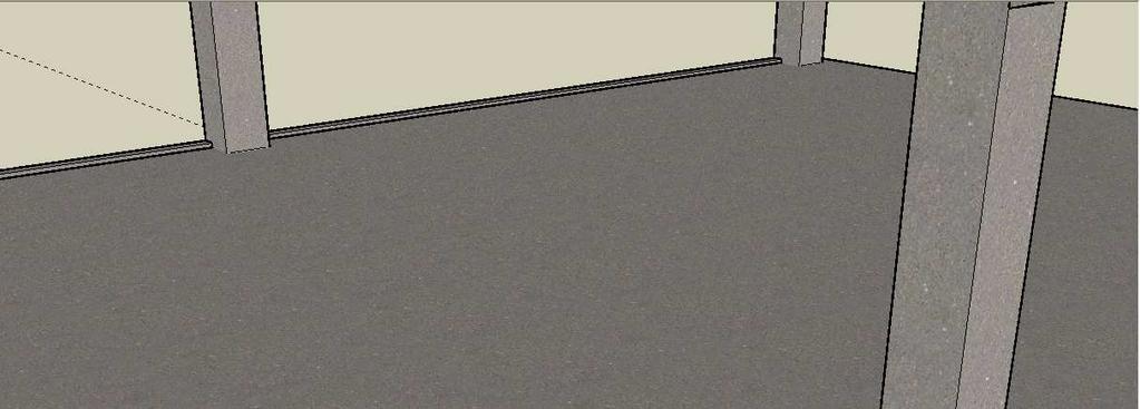
35 27 the concrete that flows into the gap between the precast beam and the face of the column. The formwork can be anchored into the column and removed once the concrete has hardened. Figures on the following pages detail in 3D representations the construction of the proposed system. Figure 3.11 Typical Column Connection Figure 3.12 Erect precast columns cast with corbels and embed plates


36 28 Figure 3.13 Erect T-RECS beams and L spandrels Figure 3.14 Make connection to precast column and install torsion restraints


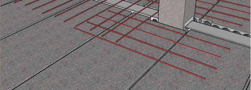
37 29 Figure 3.15 Place hollow-core on one half of beam & feed rebar into hollow-core Figure 3.16 Place second bay of hollow-core & reposition rebar


38 30 Figure 3.17 Position topping reinforcement over beams & around columns Figure 3.18 Pour CIP topping
39 31 Additional differences between the proposed system and the patented system from the literature review lie in the member connections. Figure 2.7 shows a typical bolted connection for the patented system which allows for continuous beams. These beams can also be connected to the columns using a standard bolted connection. The structural system is intended to be used in conjunction with a metal deck and CIP slab. This is also different than the hollow-core floor of the proposed system, and there is no intent to allow for the splicing together of two beams as is possible in the patented system Service Once the CIP topping hardens, it becomes a fully composite cross section with the T- RECS beam. The hardening of the CIP topping creates a moment connection between the beams and columns so that the structure now behaves as a moment frame with continuous beams. Due to the continuous beam loading, significant negative moments are generated at the face of the column. This moment must be resolved into the precast connections. The weld between the steel beam and precast column embed carries the tension force generated by these negative moments. Similarly, the compression force from the negative moment is carried by the hardened CIP topping between the precast column and the precast concrete of the T-RECS beam. At this point, any superimposed dead loads such as the mechanical, electrical, plumbing, flooring, drop ceilings, and partitions can now be installed. These loads as well as the live loads applied to the system are resisted by the fully composite cross section which
40 32 now includes the CIP concrete for the in-fill between hollow-core planks and the effective width of the CIP topping flange as prescribed in the ACI 318 (2008). There are also distinctions in the design intent between the patented system and the proposed one. The patented system is intended to be predominately a steel structure instead of concrete as evidenced by the connections and exposed steel web and top flange of the beam. It can be seen in Figure 2.7 that the designer wants to allow for M/E/P equipment to be able to pass through the voids in the steel web of the beam. This is quite different than the proposed system where reinforcing is passed through these openings, filled with concrete, and M/E/P systems must pass under the beam. The proposed system also does not have any exposed steel surfaces after pouring to the topping which is different that the patented system where the flange and web remain exposed. There are many advantages to the proposed system discussed in this chapter: All exposed surfaces are concrete. This gives the system superior fire performance characteristics over steel. The system utilizes moment connections at the columns. This allows for moment frames to be formed with the columns thereby eliminating the need for shear walls in the direction of the frame. Moment connections also make it possible for reductions in the moment demand due to continuous beam loading. The proposed system is able to achieve beam continuity while using continuous columns.
41 33 Cutting the steel beam in half in the manner proposed allows for a large reduction in the amount of steel required. The system uses all precast components with the exception of a CIP structural topping, which may be poured at any point prior to the installation of any superimposed dead loads. Having all precast components greatly increases the quality and allows for an expedited construction schedule. Perimeter L-beams act as formwork for the CIP topping thereby eliminating this costly and time-consuming process for typical CIP structures. The system is able to achieve span-to-depth ratios of over 20, which is an improvement over standard precast products. Field connections are simple, requiring only three welds at each column connection. Beams are able to resist construction loads and do not require the use of shoring during the construction process.
42 34 Chapter 4 System Analysis & Design Design Criteria The structural system developed in this paper is tailored toward applications such as residential and commercial buildings. The design criteria for these types of structures generally call for an approximate column-to-column spacing of 30 in each direction. The floor plan and a typical building section for the structure being designed for are shown in Figures 4.1 and 4.2 respectively. The overall plan dimensions for the structure are 124 x 120. Each story has a height of 10, and the building is six stories tall for a total height of 60. Span lengths for the beams are 30 at the exterior and 32 at the interior. In the opposite direction, the spans lengths for the hollow-core are 30. Span lengths at the exterior have been shortened to account for the larger moments that are present at the end spans of continuous beams. In addition to the self weight of the beams, the hollow-core, and CIP topping, a superimposed dead load (SIDL) of 15 psf is applied over the entire floor. This is to account for any M/E/P, additional flooring, drop ceiling loads, or partitions that may be required for typical office applications. ASCE 07 (2005) Table 4.1 requires that offices be designed for a minimum uniformly distributed live load of 50 psf at each floor level. The hollow-core and beams are design to meet the deflection limit of L/360 for applied live loads according to ACI 318 (2008) Table 9.5(b). For a 30 span, this requires that the service live loads do not cause deflections of more than 1. An occupancy Category
43 35 of II has been assumed for the building. The chosen location for the building is in the western portion of the state of Iowa. Non-standard manufacturing techniques or special materials would greatly add to the cost of producing the system and would limit the proposed system s commercial viability. To address this, an additional restriction imposed on the design is to limit the materials to standard materials that can be economically procured by, or produced at, typical prestressing plants. With this in mind, the following is a list of materials used for the design: Precast concrete: compressive release strength = f ci = 6500 psi 28-day compressive strength = f c = 8000 psi Prestressing strand: Reinforcing bars: Structural steel: Cast-in-place concrete: Welding electrodes: ASTM A416, 0.6ø 270 ksi low-relaxation strand ASTM A615, Grade 60 (F y = 60 ksi) ASTM A992, F y = 50 ksi, F u = 65 ksi 28-day compressive strength = f c = 4000 psi conform to AWS D1.4 with E70XX or E80EXX electrodes Plates, angles, channels, all-thread rod and other misc. shapes shall be ASTM A36 steel (F y = 36 ksi, F u = 58 ksi), UNO. Columns: Hollow-Core: 28-day compressive strength = f c = 5000 psi 28-day compressive strength = f c = 5000 psi
44 36 Figure 4.1 Typical Floor Plan Figure 4.2 Typical Building Section
45 37 Design procedures were conducted in accordance with the following design codes and manuals: Precast/Prestressed Concrete Institute (PCI) PCI Design Handbook, 6 th Edition, 2004 American Institute of Steel Construction (AISC) Steel Construction Manual, 13 th Edition, June 2008 American Society of Civil Engineers ASCE 7-05 Minimum Design Loads for Buildings and Other Structures, 2005 American Concrete Institute (ACI) Building Code Requirements for Structural Concrete (ACI318-08) and Commentary, Gravity Loads The criteria previously described are used in designing the members for the gravity loads on the system at three separate stages: Stage 1 - production, Stage 2 - erection/ construction, and Stage 3 - service. The member designs are detailed in the following sections Hollow-Core Design Hollow-core is an economical, easy to produce, and easily erected product. The hollowcore for the proposed system is similar to any conventional floor system. It comes in standard depths of 8, 10, and 12, with a standard width of 4. Design tables are available from precast manufacturers and can be used to determine the appropriate size needed for the applied loads and span length of the member. The hollow-core is designed as simply supported for gravity loads applied prior to pouring of the topping. Once the
46 38 CIP topping is poured, the continuity reinforcement previously described helps to make the hollow core continuous over the beam supports for the superimposed dead and live loads. This helps to give the hollow-core additional capacity. Stain compatibility was used to ensure adequate negative moment capacity at these supports for the continuous live loads. The following table is taken from the PCI Handbook (2004).
47 39 The boxed region in the table indicates the appropriate hollow-core strand configuration for a 30 span with a superimposed service load of 85 psf. A 4HC8+2 with a strand designation code 58-S satisfies the design requirements. This describes an 8 deep hollow-core plank with a 2 CIP structural topping and containing 5 - ½ ø strands. The typical cross section for the hollow-core is shown in Figure 4.3. Figure 4.3 Composite Hollow-Core Section T-RECS Beam Design The T-RECS beam is a prestressed member, and because of this, both stress design and ultimate strength design must be considered. The concrete should be designed to remain uncraked throughout the various stages of loading. PCI Handbook (2004), Chapter 4 details the design requirements that must be met. The stress limits used are 0.7 f c for compression and 12 f c for tension. Service loads for the various design stages can be seen in Figures 4.4 through 4.7. A summary of the section properties for each stage is provided in table 4.1. Refer to the appendix for detailed calculations of these properties. Table Summary of Section Properties A (in 2 ) I (in 4 ) y t (in) y b (in) S t (in 3 ) S b (in 3 ) Stage , Stage , Stage , ,199 1,106
48 40 Figure 4.4 Stage 1 Loads at Release Figure 4.5 Stage 2 Loads During Erection Figure 4.6 Stage 2 Loads During CIP Pour Figure 4.7 Stage 3 Loads at Service Life
49 Stage 1 Production The precast member must be designed for the first stage, which is at release of the prestressing strand. At this stage the member is analyzed as a simple span member. It is unknown exactly how much of the prestressing force is transferred to the steel beam once the prestressing force is released. The assumption made for this analysis is that the steel member is fully composite with the precast concrete; therefore, the section properties include the transformed area of the steel based on the modular ratio. Cross-sections detailing the T-RECS beam used for the design can be seen in Figures 4.8 and 4.9. Reference the elevation view in Figure 4.10 for locations of section cuts. A W18x76 was the steel section selected for the design. Figure 4.11 details the dimensions for how the steel beam should be cut to allow for proper production ø strands, tensioned to 0.78 f pu, are used to achieve the appropriate precompressive force in the concrete for stress design and moment capacity the strength design. The stress design for the beam is detailed in Table 4.2. A final concrete strength of 8 ksi with a release strength of 6.5 ksi are required to meet the stress limits for the design. Only the transformed area of the steel flange is used in the analysis, due to the uncertainty of how the cut portion of the web would behave when subjected to the prestressing force. This is a conservative assumption and should not result in an overestimation of the member s capacity. Initial stress losses in the prestressing strand due to anchorage seating and elastic shortening of the concrete were assumed to be approximately 7%. Analysis initially shows that stresses at the ends of the member are above the acceptable stress
50 42 limits for the concrete at release. To address this, the two strands in the top row are debonded at each end for 5 which reduces the stress at the ends of the member to acceptable limits. Steel Top (ksi) Table Stress Check at Release Mid-Span Conc. Bot. (ksi) Steel Top (ksi) Transfer Length Conc. Bot. (ksi) P/A Pe/S M/S Σ Limit Check OK OK OK OK Figure 4.8 Cross Section at A Figure 4.9 Cross Section at B
51 43 Figure 4.10 T-RECS Beam Elevation with Reinforcement Figure 4.11 WF Beam Manufacturing Detail
52 Stage 2 Erection During the erection of the precast, three loading cases need to be analyzed. All loads during the erection of the precast are temporary load cases, and therefore a load factor of 1.0 is applied. The first case occurs when one half of the beam is loaded with the weight of the hollowcore. This unbalanced load results in torsion being applied to the beam and the precast must be designed to resist this load. When analyzing the beam for torsion, strength of the steel beam was neglected because the torsional strength of the rectangular precast is much greater relative to the T-shaped steel section embedded in the top of the concrete. The torsion angles previously described are provided to ensure that the entire torsion force is resisted by the precast concrete and that the beam is restrained from overturning. Torsion loads were analyzed using the PCI Handbook (2004) recommended method developed by Zia and McGee. The detailed calculation of the torsion analysis is presented here and the design of the torsion restraints is detailed in the connection design section of this report. Results from the analysis require the use of 1.28 in 2 /ft not spaced at greater than 10 O.C. Stirrup placement can be seen by referencing back to Figure Stirrups are #4 bars spaced at 1½ on center which equals 1.6 in 2 /ft for the first segment of the beam where torsion is the greatest. The number of stirrups can be reduced closer the midspan where the torsion is theoretically equal to zero. The torsion design is conducted as follow:
53 45 Torsion Design bw Vu e Av+2At y h d x' y1 x1 1" TYP y' Al Note: Uses simplified PCI method which assumes f se > 40% f pu Beam Geometry *Width of stem b w = 24 in *Beam height h = 6.0 in *Depth to prestressing reinforcement d = 4.0 in *Moment of Area Σx2y = 864 in 3 *Short side of closed tie x 1 = 5 in *Long side of close tie y 1 = 20 in Material properties *Compressive strength of concrete f c = 8 ksi *Yield strength of reinforcement f y = 60 ksi *Concrete density modifier λ = 1.0 *Strand transfer length l t = 30 in *Area of prestressing strand A ps = in 2 Ultimate tensile strength of strand f pu = 270 ksi centroid of concrete after p/s losses f pc = 1.75 ksi Design load data *Factored vertical load at critical section V u = 12.3 kips *Factored moment at critical section M u = 92.4 kip_in *Factored Tosional moment T u = 130 kip_in *Section under investigation l = 3 in *Strength reduction factor φ = 0.75
54 46 Preliminary Torsion Check Prestressing factor γ = (1+10 (f pc /f c )) = 1.79 Torsion neglecting limit T umin = φ (0.5 λ (f c 1 lbs/in 2 ) Σx2y) γ = kip_in Check Shear & Torsional Limits NG - Member must be analyzed for torsion Torsion factor K t = γ (12-10 f pc /f c ) = Geometric torsion factor C t = 1in b w d / Σx2y = Maximum torsional limit T nmax =(1/3) K t λ (f c 1 lbs/in 2 ) Σx2y/ (1+(K t V u /(30 in - 1 C t T u )) 2 )=404 kip_in Maximum shear limit V nmax = 10 λ (f c 1 lbs/in 2 ) b w d/ (1+(30 in -1 C t T u /(K t V u )) 2 ) = 38 kip Ultimate combined torsion strength φt n = φ T nmax = kip_in Ultimate combined shear strength φv n = φ V nmax = kip φt n >= T u - Analysis may continue φv n >= V u - Analysis may continue Concrete Shear & Torsion Design Shear Strengths Nominal shear strength V c = (0.6 λ (f c 1 lbs/in 2 )+(700 lbs/in 2 min(1,v u d/m u ))) b w d = kip Maximum shear strength limit V cw max = 5 λ (f c 1 lbs/in 2 ) b w d = kip Minimum shear strength limit V cw min = 2 λ (f c 1 lbs/in 2 ) b w d = kip Support shear strength V cw sup = 3.5 λ (f c 1 lbs/in 2 ) b w d = kip Transition zone strength at x V cx = V cw sup + (V cw max - V cw sup ) min(l, l t ) / l t = kip Controlling value Nominal shear strength Torsional Strength V nx = kip V c = V nx = kip Nominal torsion strength T c = 0.8 λ (f c 1 lbs/in 2 ) Σx2y (2.5 γ 1.5) = kip_in Shear-Torsion Interaction Combined concrete torsional moment strength T c = T c /( (1+(T c V u /(T u V c )) 2 )) = kip_in Combined concrete shear strength V c = V c /( (1+(V c T u /(V u T c )) 2 )) = kip Reinforcement Design Closed stirrup design Spacing requirements *Spacing provided s = min(x 1 +y 1 /4, 12 in) = 10 in s prov = 4 in Pass - Spacing provided is adequate
55 47 α t = min(( y 1 /x 1 ), 1.5) = 1.5 Torsion reinforcement per leg A t = (T u /φ - T c ) s prov /(α t x 1 y 1 f y ) = 0.01 in 2 Area of shear steel required A vreq = (V u /φ - V c ) s prov /(f y d) = 0.02 in 2 Minimum area of shear steel required A vmin = A ps f pu s prov /(80 f y d) ( (d/b w )) = 0.06 in 2 Controlling area of shear steel A v = max(a vreq, A vmin ) = 0.06 in 2 Total area of stirrup reinforcing required A s = max(a v +2 A t, 50 lbs/in 2 b w s prov /f y γ 2, 200 lbs/in 2 b w s prov /f y ) = 0.32 in 2 *Shear reinforcement (user input) Diameter of strirrup bars D stir = 0.5 in Area of horizontal reinforcement provided A s_prov = 2 π D 2 stir / 4 = in 2 Longitudinal reinforcement design Pass - Torsion reinforcing is adequate Required longitudinal reinforcement A l1 = 2 A t (x 1 +y 1 )/s prov = 0.07 in 2 L = max(2 A t /s prov,min(200 lbs/in 2 b w /f y,50 lbs/in 2 b w /f y (1+12 f pc /f c ))) = in A l2 = (400 lbs/in 2 b w /f y (T u /(T u +V u /(3 in -1 C t ))) L) (x 1 +y 1 ) = in 2 Controlling longitudinal steel area A l = max(a l1, A l2 ) = 1.3 in 2 *Longitudinal reinforcement (user input) Area of prestressing strand A ps = in 2 Number of longitudinal bars n l = 12 Area of longitudinal reinforcement provided A l_prov = n l A ps = in 2 Pass - Torsion reinforcing is adequate Design Summary ~Beam height of 6.00'' by 24.0'' wide with 8000 psi concrete ~Section under investigation is located at 0.25 ft from support ~Reinforcement at section under investigation consists of 0.50 in dia vertical stirrups spaced at 4 in O.C. ~Longitudinal reinforcement consists of in dia strand. Once all of the hollow-core has been erected, two additional load cases must be checked. These loads are detailed in Figures 4.5 and 4.6 and the controlling load is shown in Figure In this design example, the load case during the pouring of the CIP topping

56 48 is the critical load case. Shear and moment diagrams for this load case are given in Figures 4.13 and 4.14 respectively. The clear span distance is 30 for the interior spans and 28 at the exterior spans. Figure 4.12 Stage 2 Uniform Dead Load Figure 4.13 Stage 2 Shear Diagram Figure 4.14 Stage 2 Moment Diagram At this stage, the entire shear force must be resisted by the precast concrete alone. This is because the loads are applied directly to the precast and the steel beam is not subjected to any shear until the CIP topping has hardened. Design of the precast is done in accordance with the PCI Design Handbook (2004). For a detailed calculation of the shear design, see the Appendix. The design requires 0.72 in 2 /ft. Reinforcement that was utilized to resist the torsion loads that are no longer present can now be considered as
57 49 reinforcement for the shear strength of the member. The amount of reinforcement required for torsion was 1.6 in 2 /ft, which exceeds the 0.72 in 2 /ft required here for shear. When analyzing the moment strength of the T-RECS beam during construction, the moment strength of the prestressing strand is not a concern because it is designed for higher factored loads during the service life of the member. However, the strength of the steel beam during this stage must be checked. The steel beam acts as the compression flange during flexure until the CIP topping has hardened. Because the steel beam is anchored in concrete at its base and has portions of the web removed, it is uncertain exactly how the steel behaves under loading. To help simplify this analysis, the steel beam is analyzed similar to any typical steel beam. This is likely a conservative assumption because a beam during flexure often undergoes lateral torsion buckling before achieving the full plastic strength of the beam. Lateral torsional buckling is a phenomenon where failure of a beam takes place normal to the plane of bending while also twisting about its shear center. This is not likely with the T-RECS beam due to the significant differences in the cross section and material properties. For instance, the moment of inertia in the weak axis for the T-RECS beam is significantly larger than a standard steel section and therefore global buckling of the beam in a lateral direction is extremely unlikely. It is possible, however, that this could occur locally in the compression flange in some similar manner. However, to be conservative the steel beam is still analyzed as if it were a W18x76 steel section unbraced for its entire length. The
58 50 results for this design are shown in table 4.3 and the detailed analysis can be seen in the Appendix. Table Flexure Analysis of Steel Beam Moment capacity φm n 374 k-ft Moment demand M u 306 k-ft Stress levels in the prestressed concrete are also checked at this stage even though it is fairly safe to assume that stress levels will be adequate because much higher loads are present during the service life. The results of the stress analysis for an interior span are shown in table 4.4. Section properties used in the calculations are based on those for Stage 2 in table 4.1. The section properties vary slightly from stage 1 due to changes in the concrete strength from 6.5 ksi at release to 8 ksi at final strength Stage 3 Service Life Table Stress Check at Erection Steel Top (ksi) Mid-Span Conc. Bot (ksi) P/A Pe/S M/S Σ Limit Check OK OK The third and final stage, which must be analyzed, is during the service life of the structure. At this stage, the CIP topping has hardened and is fully composite with the T- RECS beams. Any superimposed dead and live loads now act on the fully composite section. The structure now behaves as a moment frame with continuous beams and

59 columns, producing negative moments at the column connections. Refer to Figure 4.7 for the service loads applied at this stage for the example building. 51 First, the beam is analyzed for ultimate strength design. Figures 4.15 through 4.17 show the uniform factored loads applied prior to Stage 3 and the shear and moment diagrams for those loads. The factored loads, shear, and moment diagrams for State 3 are shown in Figures 4.18 through By using superposition, the loads previously applied are combined with the post-composite loads of Stage 3 shown in Figure 4.18 to get the total factored load applied to the beams. The final shear and moment diagrams for the design can similarly be obtained by superposition of the shear and moment diagrams for Stages 2 and 3. Figure 4.15 Stage 2 Factored Load Diagram (Pre-Composite) Figure 4.16 Stage 2 Factored Shear Diagram (Pre-Composite) Figure 4.17 Stage 2 Factored Moment Diagram (Pre-Composite)

60 52 Figure 4.18 Stage 3 Factored Load Diagram (Post- Composite) Figure 4.19 Stage 3 Factored Shear Diagram (Post- Composite) The assumed load case for the design at this point is 1.2D + 1.6L. The controlling load case will be verified upon completion of the lateral analysis conducted in subsequent sections. The final, fully composite cross section of the T-RECS beam is shown in Figures 4.21 and This section is analyzed for its shear capacity, moment capacity, and a deflection performance. Details of the column connection with component sizes are provided in Figures 4.23 and Figure 4.20 Stage 3 Factored Moment Diagram (Post- Composite)
61 53 Figure 4.21 Fully Composite Cross Section Figure 4.22 Full Composite Cross Section at Web Opening Figure 4.23 Typical Connection at Column Section
62 54 Some simplifying assumptions have been made to make calculating the shear capacity for the cross section easier because the member is a combination of prestressed concrete, reinforced concrete, and a steel beam and current design Figure 4.24 Typical Connection at Interior Column manuals to not provide specific guidelines to analyze a beam of this nature. To perform the analysis, the beam is assumed to be a prestressed concrete beam with a concrete strength equal to the topping strength because the majority of the depth of the member is the CIP topping. Also, there are too many irregularities in the steel beam to assume consistent performance for analysis as a steel member. These are conservative both fairly conservative assumptions. Completely ignoring the shear capacity of the steel is a too conservative approach so a methodology for incorporating the additional shear capacity of the T-shaped steel section must be considered as well. The assumption made is that each longer tooth of the steel beam is the equivalent of a stirrup with an area of steel equal to the cross sectional area of the stem. For this example, the stem has a minimum width of 3 with a thickness of for a total area of in 2. Each tooth is located at 12 O.C. which results in an area in 2 /ft. This is likely a conservative assumption as well because shear stress is a maximum near the neutral axis and the 3
63 55 width used is located near the bottom of the beam. A detailed calculation for the shear design can be found in the Appendix. Due to the continuous loads applied to the floor, the section must be analyzed for both positive and negative flexure. Flexural analysis of the beam for strength design is again done using strain compatibility. For the positive moment design, the area of the T-shaped flange is considered to act as longitudinal compression reinforcement. For the cross section shown, this area is equal to 7.23 in 2. An additional area of steel at the transition from the flange to the web is also included in the calculation. The effective width of the 2 CIP topping also acts as a compression element. This width is calculated according to ACI , (2008) and is equal to 52 wide. The two layers of strand, as detailed in the cross section, are the tension elements during flexure. The negative moment at the face of the column relies on the steel flange to act as tension reinforcement. This tension force is then transferred into the column through the weld to the precast embed plate. The area of the rebar in the precast embed plate must be able to carry this force to ensure that the steel flange can be fully developed. The capacity of this connection is calculated in Section Concrete from the CIP topping fills in the void between the precast beam and the column, and this concrete acts at the compression element for the negative moment. Both the negative and positive moment capacities are calculated in detail in the Appendix. The results of the design for an interior span are
 595 k-ft Moment demand - Mu (+) 468 k-ft 1.2D + 1.6L Moment capacity - φmn (-) 307 k-ft Moment demand - Mu (-) 271 k-ft 1.2D + 1.0E + L Stresses in the precast are analyzed at this stage as well.")
64 56 tabulated in Table 4.5. The governing value for the negative moment is found after completion of the lateral analysis. Table Strength Design of T-RECS Beam Shear capacity - φvn 110 kips Shear demand - Vu 96 kips 1.2D + 1.6L Moment capacity - φmn (+) 595 k-ft Moment demand - Mu (+) 468 k-ft 1.2D + 1.6L Moment capacity - φmn (-) 307 k-ft Moment demand - Mu (-) 271 k-ft 1.2D + 1.0E + L Stresses in the precast are analyzed at this stage as well. Service level load, shear, and moment diagrams applied during Stage 3 for the stress design are shown in Figures 4.25 through The total loads for stress design are obtained by superposition of loads from Stage 2, (Figures ) with those shown below. Figure 4.25 Stage 3 Service Loads Figure 4.26 Stage 3 Service Load Shear Diagram Figure 4.27 Stage 3 Service Load Moment Diagram
THE FORENSIC MEDICAL CENTER
 THE FORENSIC MEDICAL CENTER Image courtesy of Gaudreau, Inc. TECHNICAL REPORT #2 OCTOBER 26, 2007 KEENAN YOHE STRUCTURAL OPTION DR. MEMARI FACULTY ADVISOR EXECUTIVE SUMMARY Image courtesy of Gaudreau,
North Mountain IMS Medical Office Building
 North Mountain IMS Medical Office Building Phoenix, Arizona Michael Hopple Technical Assignment 2 October 29 th, 2007 AE 481W-Senior Thesis The Pennsylvania State University Faculty Adviser: Dr. Ali Memari,
Table of Contents.2. Introduction...3 Gravity Loading and Deflections..4. Existing Structural System..8
 WISCONSIN PLACE RESIDENTIAL TECHNICAL ASSIGNMENT 2 OCTOBER 29, 2007 KURT KRASAVAGE THE PENNSYLVANIA STATE UNIVERSITY STRUCTURAL OPTION FACULTY ADVISOR: DR. ALI MEMARI 1 Table of Contents Table of Contents.2
Crossroads at Westfields Building II
 Crossroads at Westfields Building II Chantilly, Va STEPHEN LUMPP Structural option Faculty Consultant: Dr. Andres Lepage Technical Report 2 EXECUTIVE SUMMARY This report is a study of alternate floor systems
Pro-Con Structural Study for Alternative Floor Systems October 27, 2004
 Ismail Al-Hadhrami Structural Option Faculty Consultant: Dr. Thomas Boothby Agricultural Hall and Annex East Lansing, MI Pro-Con Structural Study for Alternative Floor Systems October 27, 2004 Executive
151 First Side. Technical Assignment 2 November 16 th, William J. Buchko. AE 481w Senior Thesis The Pennsylvania State University
 November 16 th, 2007 William J. Buchko AE 481w Senior Thesis The Pennsylvania State University Thesis Advisor: Kevin Parfitt Table of Contents Executive Summary... 3 Structural System Overview Foundation...
Technical Report #2 10/26/06
 Photo courtesy of OTO Development, http://www.otodevelopment.com/ Dr. Memari Thesis Advisor Technical Report #2 10/26/06 Executive Summary Systems Overview Hollow Core Plank (precast) Solid Flat Slab (precast)
Alexis Pacella Structural Option Dr. Schneider Lexington II, Washington D.C. Technical Report #2 October 31,
 1 Executive Summary: Pro-Con Structural Study of Alternate Floor Systems is an investigation into possible alternative structural systems for Lexington II in Washington, D.C. For this report, several structural
North Mountain IMS Medical Office Building
 North Mountain IMS Medical Office Building Phoenix, Arizona Michael Hopple Technical Assignment 1 October 5 th, 2007 AE 481W-Senior Thesis The Pennsylvania State University Faculty Adviser: Dr. Ali Memari,
Earth and Engineering Sciences Building
 Executive Summary The purpose of this report is to provide an analysis of the existing floor system of the Earth and Engineering Sciences Building at University Park, Pennsylvania, as well as investigating
Pro-Con Structural Study of Alternate Floor Systems
 Andrew Covely Structural Dr. Linda Hanagan The Helena New York City, NY October 27, 2004 Pictures courtesy of Fox & Fowle Architects Pro-Con Structural Study of Alternate Floor Systems Executive Summary
Technical Report #2. Matthew R Peyton
 Technical Report #2 This Document is Technical Report #2 for 5th year senior thesis in the Architectural Engineering Departments at The Pennsylvania State University. This Report is to prepare a study
Kaleida Health Global Heart and Vascular Institute University at Buffalo CTRC/Incubator. Buffalo, New York. Technical Report #2
 University at Buffalo CTRC/Incubator Buffalo, New York William McDevitt October 27, 2010 Table of Contents Executive Summary...3 Introduction...4 Structural System Overview...5 Foundation...5 Floor System...5
Technical Assignment 3 December 3, 2007
 Technical Assignment 3 December 3, 2007 101 Eola Drive, Orlando, FL Justin Raducha Pennsylvania State University Faculty Advisor: M. Kevin Parfitt Table of Contents Table of Contents... 2 Executive Summary...
David A. Walenga Technical Assignment #2
 Executive Summary This report explores multiple structural design alternatives for the Residence Inn by Marriott. The existing system, precast concrete plank on steel, is the basis for comparison with
Structural Technical Report #2 Pro/Con Study of Alternate Floor Systems
 Christopher McCune Structural Option Eight Tower Bridge Faculty Advisor: Dr. Hanagan October 31 st, 2005 Structural Technical Report #2 Pro/Con Study of Alternate Floor Systems Executive Summary This technical
These systems are evaluated on the basis of serviceability issues such as:
 1 Traci Peterson Option: Structural Faculty Consultant: Memari The Del Monte Center at The North Shore Pittsburgh, PA Structural Technical Report 2 Pro Con Structural Study of Alternate Floor Systems Date
CONCRETE TECHNOLOGY CORPORATION
 PRECAST, PRESTRESSED HOLLOW CORE SLABS DESIGN CRITERIA & SPAN-LOAD CHARTS Introduction 2 Design Criteria for Development of the Span-Load Charts 2 Related Publications 3 Manufacturing Tolerances 4 8" Bare
Technical Report 1 Bed Tower Addition at Appleton Medical Center Appleton, WI
 Courtesy of HGA Technical Report 1 Bed Tower Addition at Appleton Medical Center Appleton, WI Jessel Elliott Structural 2011 Architectural Engineering Senior Thesis Studio Advisor: Dr. Richard Behr Date:
Temecula Medical Center Temecula, CA
 Temecula Medical Center Temecula, CA Technical Assignment #2 Sean F. Beville The Pennsylvania State University Architectural Engineering Structural Option Senior Thesis Project Student Advisor: Thomas
Jonathan R. Torch Technical Report 2 Columbia University. Technical Report 2. Pro-Con Structural Study of Alternate Floor Systems
 Technical Report 2 Pro-Con Structural Study of Alternate Floor Systems Columbia University Broadway & 120 th Street, New York, NY Jonathan R. Torch Pennsylvania State University Architectural Engineering
[TECHNICAL REPORT 3] Lateral System Analysis
![[TECHNICAL REPORT 3] Lateral System Analysis](/thumbs/96/126531717.jpg "[TECHNICAL REPORT 3] Lateral System Analysis") Science Center Research Park 3711 Market St. The Pennsylvania State University Department of Architectural Engineering Senior Thesis 2009-2010 Prepared by: November 30, 2009 [TECHNICAL REPORT 3] Lateral
Science Center Research Park 3711 Market St. The Pennsylvania State University Department of Architectural Engineering Senior Thesis 2009-2010 Prepared by: November 30, 2009 [TECHNICAL REPORT 3] Lateral
Technical Report 2: Pro-Con Structural Study of Alternate Floor Systems
 Gateway Plaza Wilmington, DE October 31, 2005 Elizabeth Hostutler Structural Option Advisor: Linda Hanagan Technical Report 2: Pro-Con Structural Study of Alternate Floor Systems EXECUTIVE SUMMARY The
Eric Alwine Structural Option George Read Hall The University of Delaware Dr. Boothby Technical Assignment #2 October 31, 2005 EXECUTIVE SUMMARY:
 EXECUTIVE SUMMARY: THIS REPORT IS A COMPARISON OF ALTERNATE FLOOR SYSTEMS FOR GEORGE READ HALL. FOUR DIFFERENT SYSTEMS WERE DESIGNED AND COMPARED TO THE EXISTING HAMBRO FLOOR SYSTEM. THE FOUR SYSTEMS WERE
Structural Technical Report 1 Structural Concepts / Structural Existing Conditions Report
 Michael A. Troxell Structural Option Advisor: Professor Parfitt College of Business Administration Oct. 5, 2005 Structural Technical Report 1 Structural Concepts / Structural Existing Conditions Report
Thesis Proposal. Matthew R Peyton
 This Document is for 5th year senior thesis in the Architectural Engineering Departments at The Pennsylvania State University. S t r u c t u r a l O p t i o n P r o f e s s o r B e h r H o s p i t a l
Caitlin Ferrell Structural Option Dr. Boothby, AE Faculty Consultant. Erie Convention Center and Sheraton Hotel
 Caitlin Ferrell Structural Option Dr. Boothby, AE Faculty Consultant Erie Convention Center and Sheraton Hotel Erie, Pennsylvania Technical Report #2: Pro-Con Structural Study of Alternate Floor Systems
Xyston Inn. NY. Proposal. Xiaodong Jiang. Structure Option. Advisor: Dr. Linda Hanagan
 Proposal Xiaodong Jiang Structure Option Advisor: Dr. Linda Hanagan December 12, 2014 Executive Summary Xyston Inn is a 17-story hotel building that will be located in Brooklyn, New York. The design of
SIGNAL HILL PROFESSIONAL CENTER Manassas, Virginia Morabito Consultants EXECUTIVE SUMMARY
 EXECUTIVE SUMMARY Like most suburban office building in Northern Virginia, the Signal Hill Professional Center, a four-story office structure in Manassas features composite steel construction for both
Simplified Building Schematic for Typical Floor (Levels 9 through 22):
:") Introduction to Structural System Simplified Building Schematic for Typical Floor (Levels 9 through 22): Key: - Tower Columns - Tower Shear Walls - Parking Garage Columns - Parking Garage Shear Walls Solid
Introduction to Structural System Simplified Building Schematic for Typical Floor (Levels 9 through 22): Key: - Tower Columns - Tower Shear Walls - Parking Garage Columns - Parking Garage Shear Walls Solid
Xyston Inn. NY. Proposal. Xiaodong Jiang. Structure Option. Advisor: Dr. Linda Hanagan
 Proposal Xiaodong Jiang Structure Option Advisor: Dr. Linda Hanagan December 12, 2014 Executive Summary Xyston Inn is a 17-story hotel building that will be located in Brooklyn, New York. The design of
THE PLAZA AT PPL CENTER HAMILTON BOULEVARD AT 9 TH STREET - ALLENTOWN, PA
 THE PLAZA AT PPL CENTER HAMILTON BOULEVARD AT 9 TH STREET - ALLENTOWN, PA Amy Graver, Structural Option - Dr. Hanagan, Advisor 10.21.2002 PRO-CON STRUCTURAL STUDY OF ALTERNATE FLOOR SYSTEMS Executive Summary
David A. Walenga Technical Assignment #1
 Executive Summary Contained in this report is design information related to the structural system of the Residence Inn by Marriot located in Stamford, Connecticut. Specifically, this report covers: code
Brent Ellmann Structural Option 200 Minuteman Park, Andover, MA Structural Consultant: Dr. Hanagan
 Brief Building Overview: 200 Minuteman Park stands as a 200,000 square foot Class A office building in Andover, Massachusetts, worth roughly $15,000,000. Although the building has a large square footage,
Hershey Research Park Building One. Technical Report 2. Jonathan Krepps Structural Option Advisor: Dr. Hanagan 10/12/12
 Hershey Research Park Building One Technical Report 2 Advisor: Dr. Hanagan 10/12/12 Table of Contents Executive Summary..3 Building Introduction 4 Structural Overview..5 Materials 9 Design Codes 10 Design
Trump Taj Mahal Hotel
 Trump Taj Mahal Hotel Atlantic City, New Jersey Thesis Proposal Prepared By: Stephen Reichwein, Structural Option Faculty Advisor: Dr. Andres Lepage The Pennsylvania State University Department of Architectural
Project Address: Name of Person Completing Form:
 Statement of Inspections This form is provided as a way to list aspects of the project that require special inspection and testing in accordance with IBC Sections 107.1, 1704, and 1705 and define duties
House of Sweden. Structural Study of Alternative Floor Systems K St. NW Washington, DC 20007
 Structural Study of Alternative Floor Systems 2900 K St. NW 20007 The Pennsylvania State University Department of Architectural Engineering Senior Thesis 2008-2009 October 24, 20008 Prepared by: Prepared
U.S. Pharmacopeia Headquarters Consolidation. Rockville, MD
 Consolidation Jeff Rothermel Structural Option Advisor: Dr. Ali Memari Technical Report 2 Submitted: Oct. 24 th, 2008 Table of Contents Executive Summary.1 Floor Systems Existing Two Way Slab with Drop
181 Fremont San Francisco, CA. Tech Report 3 10/17/2014. PSUAE Structural Option Advisor: Dr. Thomas Boothby
 181 Fremont San Francisco, CA Tech Report 3 10/17/2014 PSUAE Structural Option Advisor: Dr. Thomas Boothby Caroline Klatman cjk5258@psu.edu October 17, 2014 Dr. Thomas Boothby The Pennsylvania State University
AISC Steel & Timber Research for High-Rise Residential Buildings
 AISC Steel & Timber Research for High-Rise Residential Buildings Final Report December 4 th, 2017 SOM Designed Benchmark Concrete Building Skidmore, Owings, and Merrill, LLP 2017 224s Michigan Avenue Suite
Danielle Shetler - Structural option Courtyard by Marriott Lancaster, PA
 Structural Analysis Overview: During the structural analysis of the in Lancaster, Pa, a redesign of the lateral and gravity system from masonry bearing and shear walls to a staggered truss system was performed.
Anchor bolts ASTM F1554, Gr. 36 Wide flange beams ASTM A992, Fy = 50 ksi Misc. structural steel ASTM A36, Fy = 36 ksi
 STRUCTURAL NOTES MATERIAL STRENGTHS Structural Steel Reinforcing Steel Concrete Masonry Structural Lumber Anchor bolts ASTM F1554, Gr. 36 Wide flange beams ASTM A992, Fy = 50 ksi Misc. structural steel
Kaleida Health Global Heart and Vascular Institute University at Buffalo CTRC/Incubator. Buffalo, New York. Revised Thesis Proposal
 University at Buffalo CTRC/Incubator Buffalo, New York Revised William McDevitt January 14, 2011 Table of Contents Executive Summary...2 Introduction...3 Structural System Overview...4 Foundation...4 Floor
North Shore at Canton Baltimore, MD Beau Menard Technical Report 1
 North Shore at Canton Baltimore, MD Beau Menard Technical Report 1 Structural Schneider 10/05/05 Structural Concepts Executive Summary North Shore at Canton is a 4 story town home and parking garage structure
STEEL STRUCTURAL SYSTEMS
 STEEL STRUCTURAL SYSTEMS Steel elements are of two basic types: Structural steel shapes are formed into their final shapes by hot-rolling. This method produces such common elements as wide flange sections,
VARIOUS TYPES OF SLABS
 VARIOUS TYPES OF SLABS 1 CHOICE OF TYPE OF SLAB FLOOR The choice of type of slab for a particular floor depends on many factors. Economy of construction is obviously an important consideration, but this
TECHNICAL REPORT 1. Structural Concepts / Structural Existing Conditions. Penn State Hershey Medical Center Children s Hospital. Hershey, Pennsylvania
 TECHNICAL REPORT 1 Structural Concepts / Structural Existing Conditions Penn State Hershey Medical Center Children s Hospital Matthew V Vandersall The Pennsylvania State University Architectural Engineering
MOUNTAIN STATE BLUE CROSS BLUE SHIELD HEADQUARTERS
 MOUNTAIN STATE BLUE CROSS BLUE SHIELD HEADQUARTERS PARKERSBURG, WEST VIRGINIA DOMINIC MANNO STRUCTURAL OPTION FACULTY CONSULTANT: DR. ANDRES LEPAGE Technical Report 3 11-21-08 TABLE OF CONTENTS TABLE OF
Hilton Baltimore Convention Center Hotel Western Podium
 Hilton Baltimore Convention Center Hotel Western Podium CHRIS SIMMONS Structural Option Faculty Consultant: Dr. Ali M. Memari Technical Report 2 TABLE OF CONTENTS EXECUTIVE SUMMARY. Page 3 INTRODUCTION..
Structural Redesign Gravity System
 Redesign Gravity System Design Considerations A composite floor system was used for this design to maximize the efficiency of the material being used. This type of system requires less material and provides
Technical Report #1. Matthew R Peyton
 Technical Report #1 This Document is Technical Report #1 for 5th year senior thesis in the Architectural Engineering Departments at The Pennsylvania State University. This Report will include structural
SPECIAL INSPECTION AND OBSERVATION PROGRAM City of Walnut Creek Building Division. Project Address:
 SPECIAL INSPECTION AND OBSERVATION PROGRAM City of Walnut Creek Building Division Permit Application #: Project Address: Purpose: To meet the requirements of City of Walnut Creek Municipal Code Section
Thesis Proposal 12/13/06
 Photo courtesy of OTO Development, http://www.otodevelopment.com/ Dr. Memari Thesis Advisor Thesis Proposal 12/13/06 Executive Summary Structural System The in, is an eleven story hotel complex which reaches
HIGH RISE CONDO SOHO, NEW YORK, NY
 HIGH RISE CONDO SOHO, NEW YORK, NY TECHNICAL ASSIGNMENT 1 October 5, 2006 Joseph The Pennsylvania State University Structural Option Faculty Advisor: Andres Lepage TABLE OF CONTENTS TABLE OF CONTENTS 2
CONCRETE TECHNOLOGY CORPORATION
 PRECAST, PRESTRESSED HOLLOW CORE SLABS DESIGN CRITERIA & SPAN-LOAD CHARTS FOR STORM WATER DETENTION VAULT LIDS (CHARTS REVISED /18/08) Introduction Design Criteria for Development of the Span-Load Charts
Erie on the Park. Timothy Moore Penn State University Architectural Engineering Structural Emphasis Advisor: Prof. Ali Memari
 Timothy Moore Penn State University Architectural Engineering Structural Emphasis Advisor: Prof. Ali Memari Thesis Presentation - Spring 2006 Contents Introduction Building Professionals Existing Structure
Structural System. Design Criteria Fire Resistance Concrete designed for 2 HR rating (worst case) Geotechnical Report Allowable Bearing Capacity
 Geotechnical Report Allowable Bearing Capacity") System Codes and Criteria Design Codes and Standards The design code used is the Wisconsin Administrative Code along with the State of Wisconsin Department of Commerce-Safety & Buildings Chapters Comm
System Codes and Criteria Design Codes and Standards The design code used is the Wisconsin Administrative Code along with the State of Wisconsin Department of Commerce-Safety & Buildings Chapters Comm
Statement of Special Inspection Requirements
 Statement of Special Inspection Requirements California Building Code Chapter 17 Construction plans shall include a statement of special inspection in accordance with CBC chapter 17. The statement of special
Franklin Square Hospital Center Patient Tower
 Thomas Weaver Structural Option Franklin Square Hospital Center Patient Tower Baltimore, MD Thomas Weaver Structural Option AE 481W Senior Thesis Consultant: Professor M. Kevin Parfitt 12/14/2009 Page
Park Potomac Office Building E
 Kyle Wagner (IP) Advisor: Professor Kevin Parfitt 12/11/2009 Table of Contents I. Executive Summary. 3 II. Introduction / Material Strengths. 4 III. Codes and Design Standards.. 5 IV. Existing Structural
Analysis 2 Pre-fabricated Metal Stud Crete Panels-Structural Breadth
 Analysis 2 Pre-fabricated -Structural Breadth Background The current façade design calls for stick built 3-5/8 masonry on a 7-5/8 metal stud back-up with exterior sheathing board, 1 cavity board insulation
Interior Hangers. Application
 Application Interior bridge deck hangers are typically fabricated using two heavy duty sheet metal end clips that have been electrically resistance welded to an appropriate sized wire or formed metal connecting
UNION STATION EXPANSION AND RESTORATION TECHNICAL REPORT I
 UNION STATION EXPANSION AND RESTORATION WASHINGTON DC TECHNICAL REPORT I Joseph W. Wilcher III Adviser: M.K. Parfitt September 29, 2008 TABLE OF CONTENTS Executive Summary... 2 Structural Systems Foundation...
Drexel University Race Street Dormitory REVISED THESIS PROPOSAL Doug Tower Structural Advisor: Kevin Parfitt 2/7/07
 Drexel University Race Street Dormitory REVISED THESIS PROPOSAL Doug Tower Structural Advisor: Kevin Parfitt 2/7/07 Table of Contents I. Executive Summary... 3 II. Introduction... 4 III. Background...
Project. San Jose City College Physical Education Building. Prepared For. Prepared By PLACE IMAGE HERE. Ken Bauer, AIA Principal
 Project San Jose City College Physical Education Building PLACE IMAGE HERE Prepared For Ken Bauer, AIA Principal LPAS 2484 Natomas Park Drive Sacramento, CA 95833 916.443.0335 Prepared By Steve Ratchye,
Best Buy Corporate Building D (4) Richfield, MN
 Richfield, MN") Best Buy Corporate Building D (4) Thesis Proposal Professor Boothby December 12 th, 2008 Executive Summary: The Best Buy Corporate Building D is a 6 story building with a total area of 304,610 square feet.
Best Buy Corporate Building D (4) Thesis Proposal Professor Boothby December 12 th, 2008 Executive Summary: The Best Buy Corporate Building D is a 6 story building with a total area of 304,610 square feet.
Imaging Research Building
 University of North Carolina s Imaging Research Building Technical Report 2, LEED AP Structural Option Consultant- Dr. Thomas Boothby October 5, 2009 Table of Contents Executive Summary..3 Introduction...4
Southwest Housing, Arizona State University
 Prepared by KSENIA TRETIAKOVA Structural Option 01.09.2012 Architectural Engineering Pennsylvania State University 2012 Southwest Housing, Arizona State University Technical Report #3 Lateral System 01.09.2012
LIFE SCIENCES BUILDING STRUCTURAL CONCEPTS AND EXISTING CONDITIONS
 Structural Technical Report 1 LIFE SCIENCES BUILDING STRUCTURAL CONCEPTS AND EXISTING CONDITIONS Prepared for: Dr. Aly M. Said Dr. Thomas Boothby Professor Kevin Parfitt Dr. Charles D. Cox Prepared by:
Technical Report 3. Alyssa Stangl Structural Option Advisor Dr. Linda Hanagan L A J O L L A C O M M O N S P H A S E I I O F F I C E T O W E R
 Technical Report 3 Alyssa Stangl Structural Option Advisor Dr. Linda Hanagan L A J O L L A C O M M O N S P H A S E I I O F F I C E T O W E R Site and Location La Jolla Commons, San Diego, California General
Technical Report 1. Hakuna Resort Swift Water, Pennsylvania. Image Courtesy of LMN Development LLC
 Technical Report 1 Hakuna Resort Swift Water, Pennsylvania Image Courtesy of LMN Development LLC Young Jeon Structural Option Advisor: Heather Sustersic 13 September 2014 1 Table of Contents Technical
Learning Objectives. A Brief History
 Slide 1 Precast Structures and Frames Miles L. Blackman, P.E. Slide 2 Learning Objectives Discuss precast concrete characteristics, advantages and benefits, typical construction methods and construction
OVERALL STRUCTURAL SYSTEM
 EXECUTIVE SUMMARY The at the Pittsburgh International Airport, PA, is a 275,000 square foot multi-use building located directly adjacent to the airport s landside terminal. The building consists of an
Structural Technical Report 1 Structural Concepts / Existing Conditions
 Chris Shelow Structural Advisor: M. Kevin Parfitt Koshland Integrated Natural Science Center 10/05/05 AE 481W Structural Technical Report 1 Structural Concepts / Existing Conditions Executive Summary The
Campus Square Buildings C & D Lehigh University, Bethlehem, PA
 Depth Study: Structural Redesign As noted previously, Building C is the focus of the spring semester redesign, though the proposed alternatives could be applied to the other buildings in the complex, including
CORPORATE HEADQUARTERS
 TECHNICAL REPORT 1 `` CORPORATE HEADQUARTERS Great Lakes Region, U.S.A. M. JULIA HAVERTY STRUCTURAL OPTION ADVISOR: H. SUSTERSIC 12 SEPTEMBER 2014 Contents Executive Summary... 2 Purpose and Scope... 3
SJI Updates Expanded Load Tables for Noncomposite Joists / Joist Girders and Development of New Composite Joist Series
 SJI Updates Expanded Load Tables for Noncomposite Joists / Joist Girders and Development of New Composite Joist Series SUMMARY David Samuelson Steel joists are growing in recognition as being a very economical
Spring Hill Suites Marriott
 Spring Hill Suites Marriott Project Location: Amarillo, TX Prepared for: Girder Slab Technologies Contact: Daniel Fisher, Sr. January 15, 2008 Prepared by: Monica Stockmann Regional Engineer: Erika Winters-Downey
CORPORATE HEADQUARTERS
 TECHNICAL REPORT 1 REVISIONS `` Image Courtesy RTKL CORPORATE HEADQUARTERS Great Lakes Region, U.S.A. M. JULIA HAVERTY STRUCTURAL OPTION ADVISOR: H. SUSTERSIC 12 DECEMBER 2014 Contents Executive Summary...
Brent Ellmann Structural Option 200 Minuteman Park, Andover, MA Structural Consultant: Dr. Hanagan
 Structural Design: Goals: The original design of 200 Minuteman Drive was dictated largely by Brickstone Properties, the building s owner. The new design of 200 Minuteman Drive, with additional floors,
Statement of Special Inspections Michigan Building Code 2012 (MBC 2012)
") Gaines Charter Township 8555 Kalamazoo Ave SE Caledonia MI 49316 PH: 616 698-6640 Fax: 616 698-2490 www.gainestownship.org Building Department Statement of Special Inspections Michigan Building Code 2012
Gaines Charter Township 8555 Kalamazoo Ave SE Caledonia MI 49316 PH: 616 698-6640 Fax: 616 698-2490 www.gainestownship.org Building Department Statement of Special Inspections Michigan Building Code 2012
The Harry and Jeanette Weinberg Center Mercy Hospital Medical Office Building Baltimore, MD. Thesis Proposal
 The Harry and Jeanette Weinberg Center Mercy Hospital Medical Office Building Baltimore, MD Thesis Proposal Kevin Clouser December 15, 2006 Structural Option Faculty Consultant: Dr. Boothby 1 Executive
Structural Technical Report #2 By Robert Whitaker
 Structural Technical Report #2 By Robert Whitaker Robert Whitaker Structural ~ Parfitt Parkview at Bloomfield Station Bloomfield, NJ 10-31-05 Executive Summary This report covers the comparative redesign
Technical Report 1. Seneca Allegany Casino Hotel Addition. Salamanca, NY
 Technical Report 1 Seneca Allegany Casino Hotel Addition Salamanca, NY Nicholas Reed Structural Option Advisor: Prof. Parfitt Executive Summary The purpose of this technical report was to analyze the existing
Lateral System Analysis and Confirmation Design
 Andrew Covely Structural Dr. Linda Hanagan The Helena New York City, NY November 15, 2004 Pictures courtesy of Fox & Fowle Architects Lateral System Analysis and Confirmation Design Executive Summary This
Installing DELTABEAM. Installation of DELTABEAM. Deliveries. Storage on-site
 Installing DELTABEAM Installation of DELTABEAM These DELTABEAM installation instructions are intended to complement the project s erection plan. Peikko s technical support can help with the erection plan
Stephan Northrop Structural Option Dr. Linda Hanagan. North Shore Equitable Building Pittsburgh, PA Senior Thesis Proposal
 Stephan Northrop NORTHROP THESIS PROPOSAL PAGE - 1 TABLE OF CONTENTS Executive Summary.. 3 1. Introduction.. 4 2. Structural Systems.. 5 Foundation.. 5 General Floor Framing.. 6 Turret Framing.. 7 Roof
Design Criteria. Analysis and Design of a High Rise Steel Braced Frame Core 22
 Analysis and Design of a High Rise Steel Braced Frame 22 Design Criteria Design Methodology The design of a high rise lateral force resisting system and gravity system poses itself as a daunting and cumbersome
SPECIAL INSPECTION AGREEMENT
 PART 1 STATEMENT OF SPECIAL INSPECTIONS When special inspection is required to be performed in accordance with International Building Code Chapter 17, a building permit cannot be issued until a statement
A MEDLEY OF PRECAST AND PRESTRESSED CONCRETE SYSTEMS
 A MEDLEY OF PRECAST AND PRESTRESSED CONCRETE SYSTEMS Neil F. Dunbar Ketch u m-kon ke l-barrett-n i cke I-A u sti n Consulting Engineers Denver, Co!oredo Describes several structural systems using both
William W. Wilkins Professional Building Columbus, Ohio
 William W. Wilkins Professional Building Columbus, Ohio Technical Assignment 1 October 5, 2006 Michelle Structural Option AE 481W Senior Thesis Faculty Advisor: Dr. Boothby Table of Contents Executive
The Structural Redesign of Boyds Bear Country and its Related Systems. Boyds Bear Country, Pigeon Forge, Tennessee
 The Structural Redesign of Boyds Bear Country and its Related Systems Included in this Presentation: Background and Existing System Proposal Problem / Solution Structural System Redesigns Pre-cast Concrete
Brent Ellmann Structural Option 200 Minuteman Park, Andover, MA Structural Consultant: Dr. Hanagan
 Executive Summary: 200 Minuteman Park currently stands as a three story commercial building. The original design was limited to three stories by an industrial zoning law in Andover, Massachusetts. If this
Kiski Area High School Allegheny Township, PA FLOOR SYSTEM ANALYSIS
 FLOOR SYSTEM ANALYSIS Objective The objective of the following breadth study is to determine if an alternative floor system for Building N would be more advantageous than the existing floor system. The
Structural Technical Report I October 5, 2006 Structural Concepts / Structural Existing Conditions Report
 1 THE ODYSSEY ARLINGTON, VA Aaron Snyder Structural Option Advisor: M. Kevin Parfitt, PE Structural Technical Report I October 5, 2006 Structural Concepts / Structural Existing Conditions Report Executive
Thesis Proposal Structural Redesign / Cost, Schedule and Coordination Analysis / Architectural Impact
 Thesis Proposal Structural Redesign / Cost, Schedule and Coordination Analysis / Architectural Impact Executive Summary:, located in Pigeon Forge, Tennessee, is designed as a multifunctional space and
Lateral System Analysis and Confirmation Design November 15, 2004
 Jonathan Hill Structural AE Faculty Consultant Dr. Hanagan Lynde and Harry Bradley School of Technology & Trade Milwaukee, Wisconsin Lateral System Analysis and Confirmation Design November 15, 2004 Executive
Thesis Proposal. Aquablue at the Golden Mile. Hato Rey, Puerto Rico
 Thesis Proposal Hato Rey, Puerto Rico Lindsay Lynch Structural Option Dr. Andres Lepage 20 January 2009 Table of Contents Executive Summary.......................................................... 2 General
Structural Tests and Special Inspections Form. Inspection of Fabricators (1704.2)
") Inspection of Fabricators (1704.2) Furnish inspection reports (1704.2.1) - Fabricators that have not been approved Provide a Certificate of Compliance (1704.2.2) - Approved Fabricators Steel Construction
Inspection of Fabricators (1704.2) Furnish inspection reports (1704.2.1) - Fabricators that have not been approved Provide a Certificate of Compliance (1704.2.2) - Approved Fabricators Steel Construction