DISTRIBUTION SILICONE INSULATORS Deadend / Suspension 15 kv to 69 kv
|
|
|
- Priscilla Turner
- 6 years ago
- Views:
Transcription

1 K-LINE INSULATORS LIMITED TORONTO, ONTARIO, CANADA Catalogue D-DS DISTRIBUTION SILICONE INSULATORS Deadend / Suspension 15 kv to 69 kv ISO9001 SAI GLOBAL FILE No
2 Distribution Silicone Insulators Deadend / Suspension In general Overhead Distribution Lines tend to experience a large number of outages and interruptions due to insulation failures. These failures may be from surface contamination or wetting on line insulators that result in flashovers or pole fires. Silicone Deadend/Suspension Insulators offer the ultimate solution in improved performance. Because of its hydrophobicity, this material inherently resists water filming thereby limiting leakage currents. Insulators with reduced leakage currents, even when contaminated, require less frequent washing. The savings in such maintenance costs are added benefits of using silicone insulators. K LINE INSULATORS LIMITED (KLI) silicone Distribution Deadend/Suspension Insulators are manufactured and tested to world-class polymer insulator standards; CSA C411.5, ANSI C29.13, and IEC K-LINE INSULATORS LIMITED is registered to ISO 9001 Quality Systems. PERFORMANCE BENEFITS The performance benefits of KLI Distribution Deadend/Suspension Insulators are listed below. Improves Reliability (by minimizing interruptions and outages due to vandalism, pole fires, and flashovers in all types of environments) Eliminates or Reduces Maintenance (such as washing and trouble calls) and is compatible with existing plant Improves Power Quality (less RI and TVI) Energy Efficiency (lower losses due to lower leakage currents) Safety (light weight for handling and installation) Service Life (consistent performance over its service life) Life Cycle Cost (savings over porcelain insulators) APPLICATION Distribution Deadend/Suspension Insulators are used on overhead lines operating at or below 69 kv. These insulators are used to support line conductors in suspension or deadend modes such as line terminations, angles, and tangents. These insulators can be used with bare or covered conductors. CORE ROD The core rod of the insulator is made of a high quality, epoxy resin, E-Glass fiberglass rod that has been specially formulated for electrical and mechanical applications. HOUSING The housing (includes sheath and sheds) of the insulator is one piece, high temperature vulcanized, injection molded silicone rubber that is chemically bonded to the core rod. This ensures that the interface between the rubber and rod is impenetrable against moisture ingress. KLI uses its own proprietary silicone rubber formula in the manufacture of its insulators. The formulation has silicone rubber as the base polymer material with additives to enhance its performance in wet and contaminated environments. 2
3 DISTRIBUTION DEADEND/SUSPENSION INSULATORS TECHNICAL DATA SPECIFICATIONS UNIT CATALOGUE NUMBER** KL15ASCTM KL28ASCTM KL35SCTM KL46SCT KL46SCTA KL69HC1T116 Voltage Class kv CSA & ANSI Class - DS15 DS28 DS35 DS46 - DS69 Section Length L mm (in) 322 (12.7) 433 (17.0) 486 (19.1) 574 (22.6) 646 (25.4) 733 (28.9) Dry Arcing Distance mm (in) 193 (7.6) 290 (11.4) 348 (13.7) 419 (16.5) 490 (19.3) 627 (24.7) Leakage Distance mm (in) 384 (15.1) 590 (23.2) 750 (29.5) 988 (38.9) 1059 (41.7) 1798 (70.8) Low-Frequency Dry kv Flashover Wet kv Positive Critical Impulse Flashover kv Radio Influence Voltage Test kv (RIV) at 1 MHz Max. V Below 1 Below 1 Below 3 Below 3 Below Specified Mechanical Load (SML) kn (lb) 70 (15,750) 70 (15,750) 70 (15,750) 90 (20,230) 90 (20,230) 90 (20,230) Torsional Load Nm (ftlb) 62 (45) 62 (45) 62 (45) 62 (45) 62 (45) 62 (45) Approx. Weight kg (lb) 0.7 (1.5) 0.8 (1.8) 1.1 (2.5) 1.4 (3.0) 1.6 (3.5) 2.2 (4.8) Standard Packaging ** The catalogue numbers in the above table are for CT clevis-tongue fittings. For other combinations of end fittings, specified mechanical strengths or material, see End Fittings Section. 3
4 END FITTINGS There are six standard end fittings that are available on the Deadend/Suspension Insulators: Clevis, Tongue, Oval Eye, Y Clevis, Socket and Ball (See Below). The Clevis and Tongue fittings are made from high strength, corrosion resistant extruded aluminum or hot-dip galvanized iron or steel. While the socket, ball, thimble eye, oval eye, and y clevis fittings are made from hot-dip galvanized iron or steel. The end fittings are crimped on to the core rod to provide the mechanical performance. A watertight seal between the rubber and end fittings eliminates moisture ingress. This special silicone rubber to metal fittings sealing process provides total exclusion of moisture. The end fittings of the Distribution Class Deadend/Suspension are rated for a specified mechanical strength, SML of 70 kn (15,750 lb) or 90 kn (20,230 lb). The Clevis and Tongue end fittings are the two most common fittings used with additional adaptors and clamps. For other special end fittings please contact KLI. End Fitting END FITTING RATINGS AND DIMENSIONS End Fitting Designation Material SML kn (lbs) Class Dimensions (in) A B C D E Oval Eye E Galvanized Iron 90 (20,230) Y-Clevis Y Galvanized Iron 90 (20,230) Socket S Galvanized Steel 90 (20,230) ANSI IEC Ball B_IEC Galvanized Steel 90 (20,230) IEC 16A 16 mm ANSI Ball B Galvanized Steel 90 (20,230) ANSI C_F Galvanized Iron 70 (15,750) Clevis 70 (15,750) C Aluminum 90 (20,230) T_F Galvanized Iron 70 (15,750) Tongue 70 (15,750) T Aluminum 90 (20,230) K-LINE INSULATORS LIMITED 50 Passmore Avenue, Toronto, Ontario, Canada M1V 4T1 Tel.: (416) Fax: (416) insulators@k-line.net Web Page: October

5 K-LINE INSULATORS LIMITED Catalogue D-LP DISTRIBUTION SILICONE INSULATORS Line Post 15 kv to 69 kv ISO9001 SAI GLOBAL FILE No
6 Distribution Silicone Insulators Line Post Insulator contamination is a common problem on overhead lines. The fundamental element for interruptions with contaminated insulators is moisture. Wet atmospheric conditions result in water filming on surfaces and causing leakage currents to develop. On wood structures, leakage currents can cause pole fires. On steel structures, leakage currents can develop into faults. Silicone rubber formulations offer the ultimate solution in Line Post Insulator material. Due to its hydrophobicity, this material inherently resists water filming thereby limiting leakage currents. Silicone rubber insulators reduce leakage currents, even when contaminated and require less frequent washing. The savings in such maintenance costs are added benefits of using Silicone Rubber Insulators. K-LINE INSULATORS LIMITED (KLI) silicone Distribution Line Post Insulators are manufactured to meet world-class polymer insulator standards, CSA C411.6, IEC and ANSI C K-LINE INSULATORS LIMITED is registered to ISO 9001 Quality Systems. PERFORMANCE BENEFITS The performance benefits of KLI Distribution Line Post Insulators are listed below. Improves Reliability (by minimizing interruptions and outages due to vandalism, pole fires, and flashovers in all types of environments) Eliminates or Reduces Maintenance (such as washing and trouble calls) and is compatible with existing plant Improves Power Quality (less RI and TVI) Energy Efficiency (lower losses due to lower leakage currents) Safety (light weight for handling and installation) Service Life (consistent performance over its service life) Life Cycle Cost (savings over ceramic insulators) APPLICATION Distribution Silicone Line Post Insulators are used on overhead distribution lines operating at and below 69 kv. These insulators are commonly installed on metal, concrete or wooden structures to horizontally or vertically support the line conductor. Also, these insulators can be used to support high voltage conductor jumpers or leads. CORE ROD The core rod of the insulator is made of a high quality, epoxy resin, E-Glass fiberglass rod that has been specially formulated for electrical and mechanical applications. HOUSING The housing (includes sheath and sheds) of the insulator is one piece, high temperature vulcanized, injection molded silicone rubber that is chemically bonded to the core rod. This ensures that the interface between the rubber and rod is impenetrable against moisture ingress. KLI uses its own proprietary silicone rubber formula in the manufacture of its insulators. The formulation has silicone rubber as the base polymer material with additives to enhance its performance in wet and contaminated environments. 2
7 END FITTINGS LINE END FITTING The line end fitting of Line Post Insulators are available in four different configurations: Horizontal or Vertical Clamp-Top, Tie-Top, or K-CLAMP. End fittings on Line Post Insulators are made of corrosion resistant aluminum alloy or galvanized iron castings. SECTION LENGTH ADJUSTMENT Line End Fitting Line End Fitting Designation Section Length K-CLAMP K See Technical Data sheet Horizontal H L - 9 mm (0.4 ) Vertical V L - 23 mm (0.9 ) Tie-Top (F-neck) TF L - 33 mm (1.3 ) Tie-Top (C-neck) T L - 53 mm (2.1 ) Clamp-Top The conventional horizontal and vertical trunnion accommodates a standard Line Post Insulator, bolted conductor clamp. On the horizontal design the line end fitting has an additional eye for the attachment of other devices during installation or maintenance activities. Tie-Top The tie-top is designed for tying a conductor to the neck of the insulator. It is available in two standard neck sizes: C or F-neck. K-CLAMP K-LINE introduced the original K-CLAMP concept in the polymer Line Post live end fitting design. The uniqueness of this end fitting is a result of the many advantages it has over the traditional horizontal, vertical and tie-top configurations. Some advantages of the K-CLAMP include: 1) Excellent corrosion resistant aluminum casting 2) A long, smooth contoured conductor clamping zone 3) The clamp accommodates a full range of conductor sizes 4) A single captive live-line operable bolt 5) All parts are captive 6) Its overall length permits standard cover up hoods to effectively cover all insulator sheds 7) The design can be installed in either a horizontal or vertical configuration 8) Inventory reduction is accomplished because one insulator is used for both configurations and a separate clamp is not required 9) The price of the new insulator is cost comparative with the purchase of a standard trunnion post insulator and a separate clamp 10) Substantial labour cost savings in stringing, sagging and conductor clamping 11) Other savings related to shipping, stocking and maintenance BASE END FITTING The standard base for Line Post Insulators is a round flat iron base with a threaded hole that accommodates a standard insulator stud or bolt. For other special bases contact KLI. Hot-dip galvanizing to CSA G164 or ASTM A153 specifications provides corrosion protection of the base end fitting. 3
8 LINE POST INSULATORS Conductor diameter range is [5.1mm (0.20") mm (1.34")] K-CLAMP TM H-Horizontal V-Vertical TF or T-Tie Top TECHNICAL DATA KL69S SPECIFICATION UNIT CATALOGUE NUMBER* KL15S_ KL28S_ KL35S_ KL46S_ KL69S_P KL69S_ KL69S_P1 Voltage Class kv CSA Class - LP15 - LP28M LP46 LP46M LP46M LP69M ANSI Class C, 51-1F, 51-11, 51-21, C, 51-2F, 51-12, C, 51-3F, 51-13, 51-23, C, 51-4F, 51-14, 51-24, , 51-25, , 51-25, * Ordering Information To catalogue number, add suffix H for horizontal, V for vertical, T for C-neck Tie-top, TF for the F-neck Tie-top, or K for K-CLAMP. The standard base thread is 3/4-10 UNC, except for KL69S_P1 it has 7/8-9 UNC. Different base threads are available upon request. ** For KL69S_P & KL69S_P1 insulators with 3/4 threaded base, a minimum Grade 5 bolt or stud must be used. *** Section lengths are for K-CLAMP insulators. For others refer to Section Length Adjustment Table under End Fittings , 51-26, Section Length (L)*** mm (in) 297 (11.7) 348 (13.7) 424 (16.7) 500 (19.7) 571 (22.5) 619 (24.4) 694 (27.3) Dry Arcing Distance mm (in) 138 (5.4) 184 (7.2) 264 (10.4) 339 (13.3) 445 (17.5) 478 (18.8) 551 (21.7) Leakage Distance mm (in) 275 (10.8) 420 (16.5) 657 (25.9) 860 (33.9) 1171 (46.1) 1121 (44.1) 1511 (59.5) Positive Critical Impulse Flashover kv Low-Frequency Flashover Radio Influence Voltage (RIV) at 1000 khz Dry kv Wet Test kv Max V Specified Tensile Load (STL) kn (lb) 22 (5000) 22 (5000) 22 (5000) 22 (5000) 22 (5000) 22 (5000) 22 (5000) Specified Cantilever Load (SCL) kn (lb) 12.5 (2800) 12.5 (2800) 12.5 (2800) 12.5 (2800) 12.0 (2700) 14.0 (3150) 11.0 (2475) Max. Design Cantilever Load (MDCL) kn (lb) 6 (1350) 6 (1350) 6 (1350) 6 (1350) 6.0 (1350) 7.0 (1575) 5.5 (1240) Number of Sheds Approx. Weight kg (lb) 4.1 (9.0) 4.3 (9.5) 4.8 (10.5) 5.8 (12.8) 7.0 (15.4) 10.1 (22.2) 8.4 (18.4) Standard Packaging K-LINE INSULATORS LIMITED 50 Passmore Avenue, Toronto, Ontario, Canada M1V 4T1 Tel.: (416) Fax: (416) insulators@k-line.net Web Page: March

9 New Silicone Line Post Insulator For 69 kv Overhead Lines K-LINE INSULATORS LIIMITED (KLI) has introduced a new silicone line post insulator that is applicable for 69 kv overhead lines. This insulator is designed for installations with high electrical requirements. This insulator features the highly reliable proprietary KLI silicone rubber that is one piece, injection molded and chemically bonded to a high quality epoxy fiberglass rod. This insulator will greatly improve the electrical performance of the System, especially in contaminated environments. Insulator contamination is a common problem on overhead lines. The fundamental element for interruptions with contaminated insulators is moisture. Wet atmospheric conditions result in water filming on surfaces and causing leakage currents to develop. On wood structures, leakage currents can cause pole top fires and eventual failures. On steel structures, leakage currents can develop into faults. KLI s proprietary silicone rubber offers the ultimate solution in post insulator applications. Because of its hydrophobicity, this material inherently resists water filming thereby limiting leakage currents. These silicone rubber insulators reduce leakage currents, even when contaminated and require less frequent if any washing. The savings in maintenance costs are added benefits of using KLI silicone rubber insulators. The 69 kv line post insulator has been designed to meet the requirements of CSA C411.6, ANSI C29.18, and IEC The 69 kv line post insulator is available in four different configurations: Horizontal, Vertical, Tie-Top, or K-Clamp. The K-CLAMP design offers the best and most cost effective solution in most cases. 69 kv K-CLAMP Line Post The K-CLAMP Line Post insulator has an integral clamp for attaching the conductor directly to the line post insulator without the use of a separate conductor clamp. The K- CLAMP can be mounted either in the vertical or horizontal position and offers several advantages over conventional line post insulators. The K-CLAMP has a smooth clamping zone that accommodates a conductor diameter range of 0.20 inch (5.1 mm) to 1.34 inch (34 mm). The single galvanized steel clamp bolt that secures the keeper can be operated with hot line tools from either side of the clamp. It also extends beyond the clamp body to allow for the attachment of stringing devices. The K-CLAMP provides substantial labour cost savings in stringing, sagging and conductor clamping. There are other savings that can be achieved in shipping, stocking and maintenance.
. Conductor clamps are also available.")
 at 1 MHz Test kv 45 Max µv 6 CSA Class - LP69M Specified Tensile Load (STL) kn (lb) 22 (5000) ANSI Class - 51-16 & 51-26 Specified Cantilever Load")
 8.0 (17.")

10 Configuration & Hardware Accessories The 69 kv line post is available in three other configurations: vertical, horizontal, or tie-top (ANSI F-Neck). Also, the horizontal line post can be supplied with a gain base (See below). Conductor clamps are also available. Vertical Tie-Top Horizontal with Gain Base Technical Data SPECIFICATION UNIT CATALOGUE NUMBER* SPECIFICATION UNIT KL69S CATALOGUE NUMBER* KL69S Voltage Class kv 69 Radio Influence Voltage (RIV) at 1 MHz Test kv 45 Max µv 6 CSA Class - LP69M Specified Tensile Load (STL) kn (lb) 22 (5000) ANSI Class & Specified Cantilever Load (SCL) kn (lb) 11 (2475) Dry Arcing Distance Leakage Distance mm (in) mm (in) 551 (21.7) Max. Design Cantilever Load (MDCL) kn (lb) 5.5 (1240) 1511 (59.5) Approx. Weight kg (lb) 8.0 (17.5) Critical Impulse Flashover (Positive) kv 360 Standard Packaging - 2 Low-Frequency Flashover Dry 235 kv Wet 190** * Ordering Information To Line Post Catalogue Number, add suffix KP1 for K-CLAMP, HP1 for horizontal, VP1 for vertical, or TFP1 for tie-top. The standard base thread is ⅞ -9 UNC. Different base threads are available upon request. ** The value shown is as per CSA and the ANSI value is 165 kv. K-LINE INSULATORS LIMITED 50 Passmore Avenue, Toronto, Ontario, Canada M1V 4T1 Tel.: (416) Fax: (416) insulators@k-line.net Web Page: March

11 K-LINE INSULATORS LIMITED Catalogue D-SP TORONTO, ONTARIO, CANADA DISTRIBUTION SILICONE INSULATORS Station Post 15 kv to 46 kv ISO9001 SAI GLOBAL FILE No
12 Distribution Silicone Insulators Station Post One of the most critical assets of an electrical Distribution System is the station. Not only is this asset the heart of the supply to large electrical loads but it also serves many customers from industrial to residential. Therefore, power outages or interruptions due to insulation failures are costly and impact negatively on customer service. With K- LINE INSULATORS LIMITED (KLI) silicone Station Post Insulators these are greatly minimized through improved performance to reliability and savings in the life cycle cost. Silicone s hydrophobic property allows KLI Station Post Insulators to electrically outperform ceramic insulators. The lightweight feature of polymer insulators makes them easy to handle and install. The size and fittings of polymer Station Post Insulators ensure that they are compatible with existing Station Post hardware and arrangements. Experience with silicone polymer insulators has proven their superiority over ceramic insulators. KLI silicone Distribution Station Post Insulators are manufactured and tested to world-class polymer insulator standards, CSA and ANSI. K-LINE INSULATORS LIMITED is registered to ISO 9001 Quality Systems. PERFORMANCE BENEFITS The performance benefits of KLI Distribution Station Post Insulators are listed below. Improves Reliability (interruptions and outages due to vandalism, and flashovers in all types of environments are a thing of the past) Eliminates or Reduces Maintenance (such as washing and trouble calls) and are compatible with existing ceramic insulators Improves Power Quality (lower RI and TVI) Energy Efficiency (reduced losses due to lower leakage currents) Safety (light weight for handling and installation, eliminates catastrophic mechanical failures) Service Life (consistent performance over its service life) Life Cycle Cost (savings over ceramic insulators) APPLICATION Distribution Station Post Insulators are used in open-type stations operating at and below 46 kv. These insulators support the bus, leads, or other apparatus within the station. CORE ROD The core rod of the insulator is made of a high quality, epoxy resin, E-Glass fiberglass rod that has been specially formulated for electrical and mechanical applications. HOUSING The housing (includes sheath and sheds) of the insulator is one piece, high temperature vulcanized, injection molded silicone rubber that is chemically bonded to the core rod. This ensures that the interface between the rubber and rod is impenetrable against moisture ingress. KLI uses its own proprietary silicone rubber formula in the manufacture of its insulators. The formulation has silicone rubber as the base polymer material with additives to enhance its performance in wet and contaminated environments. 2
13 DISTRIBUTION STATION POST INSULATORS SPECIFICATION UNIT TECHNICAL DATA CATALOGUE NUMBER* KL15SCP KL25SC KL25SP KL25SPN KL35SP KL46SPT2 KL46SPP Voltage Class kv ANSI Technical Reference (TR) No. 4 & Section Length (L) mm (in) 254 (10) 305 (12) 356 (14) 381 (15) 457 (18) 559 (22) 559 (22) Dry Arcing Distance mm (in) 145 (5.7) 184 (7.2) 259 (10.2) 267 (10.5) 339 (13.3) 478 (18.8) 460 (18.1) Leakage Distance mm (in) 275 (10.8) 420 (16.5) 630 (24.8) 657 (25.9) 860 (33.9) 1121 (44.1) 1201 (47.3) Impulse Withstand kv Positive Critical Impulse Flashover kv Low-Frequency Wet Withstand kv Radio Influence Voltage (RIV) at 1000 khz Specified Tensile Load (STL) Specified Cantilever Load (SCL) Test kv Max V kn (lb) (10000) (10000) (10000) (10000) (10000) (10000) (10000) kn (lb) (2800) (2800) (2800) (2800) (2800) (3150) (2700) Max Design Cantilever Load (MDCL) kn (lb) 6 (1350) 6 (1350) 6 (1350) 6 (1350) 6 (1350) 7 (1575) 6.0 (1350) Number of Sheds No Approx. Weight kg (lb) 5.0 (11.0) 5.2 (11.5) 5.5 (12.0) 5.9 (12.9) 6.0 (13.4) 9.1 (20.0) 7.0 (15.4) * Ordering Information: 1. Above catalogue numbers apply to insulators with through holes on both ends. (Except for KL46SPT2). 2. Add T1 to catalogue numbers for insulators with one end tapped & the other with through holes. 3. Add T2 to catalogue number for insulators with both ends tapped. 3
14 END BASES The standard base fittings are flat round iron bases that are available with bolt circle mounting holes with either through or tapped holes. These bases are compatible with the ceramic Station Post Insulator standard. The end bases are radially swaged on to the core rod to provide the mechanical performance and reduce the stress concentration. Our proprietary design ensures a watertight seal between the rubber and end fitting. This special silicone rubber to metal fittings sealing process prevents moisture ingress to the core fiberglass rod. For other special base requirements, please contact KLI. Corrosion protection of the end bases is provided by hot-dip galvanizing to CSA G164 or ASTM A153 specifications. K-LINE INSULATORS LIMITED 50 Passmore Avenue, Toronto, Ontario, Canada M1V 4T1 Tel.: (416) Fax: (416) insulators@k-line.net Web Page: 4 October 2013

15 K-LINE INSULATORS LIMITED TORONTO, ONTARIO, CANADA Catalogue T-DS TRANSMISSION SILICONE INSULATORS Deadend / Suspension 69 kv to 400 kv ISO9001 SAI GLOBAL FILE No
16 Transmission Silicone Insulators Deadend / Suspension One of the most important items on any overhead transmission line is the insulator. This item is the backbone of the transmission system in minimizing interruptions, outages, and assuring system safety and reliability. Therefore, it is essential to have high quality and dependable insulators on the system. With K-LINE INSULATORS LIMITED silicone rubber transmission insulators these objectives can be easily achieved with a substantial savings in the life cycle cost. Experience with silicone polymer insulators has proven their superiority over ceramic insulators. Today more Electric Utilities are shifting to silicone polymer insulators to improve overall performance on transmission lines. KLI Transmission Silicone Suspension/Deadend Insulators are manufactured to meet world-class polymer insulator standards, CSA C411.4, ANSI C29.12 and IEC K-LINE INSULATORS LIMITED is registered to ISO 9001 Quality Systems. PERFORMANCE BENEFITS The performance benefits of KLI Transmission Suspension/Deadend Insulators are listed below. Improves Reliability (interruptions and outages due to vandalism, pole fires, and flashovers in all types of environments are a thing of the past) Eliminates or Reduces Maintenance (such as washing and trouble calls) and is compatible with existing plant Improves Power Quality (less RI and TVI) Energy Efficiency (lower losses due to lower leakage currents) Safety (light weight for handling and installation) Service Life (consistent performance over its service life) Life Cycle Cost (savings over ceramic insulators) APPLICATION Transmission Suspension/Deadend Insulators are used on transmission lines operating at and above 60 kv. These insulators are installed on support structures to hold conductors longitudinally (dead-end) or vertically (suspension). The connections to the structure attachment point and line vary depending on the line design or Utilities preference. CORE ROD The core rod of the insulator is made of a high quality, epoxy resin, E-Glass or ECR fiberglass rod that has been specially formulated for electrical and mechanical applications. HOUSING The housing (includes sheath and sheds) of the insulator is one piece, high temperature vulcanized, injection molded silicone rubber that is chemically bonded to the core rod. This ensures that the interface between the rubber and rod is impenetrable against moisture ingress. KLI uses its own proprietary silicone rubber formula in the manufacture of its insulators. The formulation has silicone rubber as the base polymer material with additives to enhance its performance in wet and contaminated environments. 2
17 TRANSMISSION DEADEND / SUSPENSION INSULATORS - 90 kn (20,000 lbs) TECHNICAL DATA: All values refer to insulators with the appropriate voltage class corona rings installed. (Note 1) Catalogue Number Voltage Class Section Length (Note 2) L Dry Arcing Distance Leakage Distance Positive Critical Impulse Flashover Impulse Withstand Low Frequency Dry Low Frequency Wet Weight (Note 3) kv mm (in) mm (in) mm (in) kv kv Flashover kv Withstand kv Flashover kv Withstand kv KL69HB1S (24.9) 526 (20.7) 1466 (57.7) (4.3) KL69HB1S (29.0) 627 (24.7) 1798 (70.8) (5.2) KL69HB1S (33.1) 732 (28.8) 2131 (83.9) (6.0) KL115HB1S (37.1) 815 (32.1) 2461 (96.9) (7.2) KL115HB1S (41.2) 917 (36.1) 2794 (110.0) (8.0) KL115HB1S (45.3) 1021 (40.2) 3127 (123.1) (8.9) KL138HB1S (49.3) 1125 (44.3) 3460 (136.2) (9.8) KL138HB1S (53.4) 1227 (48.3) 3792 (149.3) (10.7) KL138HB1S (57.5) 1331 (52.4) 4125 (162.4) (11.1) KL161HB1S (61.6) 1420 (55.9) 4458 (175.5) (14.4) KL161HB1S (65.6) 1521 (59.9) 4790 (188.6) (15.3) KL161HB1S (69.7) 1628 (64.1) 5123 (201.7) (16.2) KL230HB1S (73.8) 1702 (67.0) 5456 (214.8) (17.0) KL230HB1S (77.9) 1803 (71.0) 5789 (227.9) (17.9) KL230HB1S (81.9) 1908 (75.1) 6121 (241.0) (18.8) kg (lb) Notes: 1. See page 8 for correction factors for values for insulators without corona rings. 2. Section lengths are based on ANSI ball and socket hardware and 90 kn (20,000 lbs) SML rating. For lengths of insulators with alternate end fittings combination see Section Lengths. 3. Weight includes standard rings where applicable. See section on Corona Rings The formula for the catalogue number of a typical insulator is shown below. For specific catalogue number please contact KLI. Cat. No. KL 115 H B1S1 28 X Company ID Other Options Voltage Class (See Tech. Data No. of Sheds (See Tech. Data) High Leakage End Fitting Designation (See End Fittings) 3
18 TRANSMISSION DEADEND / SUSPENSION INSULATORS kn (27,000 lbs) TECHNICAL DATA: All values refer to insulators with the appropriate voltage class corona rings installed. (Note 1) Catalogue Number Voltage Class Section Length (Note 2) L Dry Arcing Distance Leakage Distance Positive Critical Impulse Flashover Impulse Withstand Low Frequency Dry Low Frequency Wet Weight (Note 3) kv mm (in) mm (in) mm (in) kv kv Flashover kv Withstand kv Flashover kv Withstand kv KL69HBS (26.0) 526 (20.7) 1466 (57.7) (6.3) KL69HBS (30.0) 627 (24.7) 1798 (70.8) (7.2) KL69HBS (34.1) 732 (28.8) 2131 (83.9) (8.0) KL115HBS (38.2) 815 (32.1) 2461 (96.9) (9.2) KL115HBS (42.3) 917 (36.1) 2794 (110.0) (10.0) KL115HBS (46.3) 1021 (40.2) 3127 (123.1) (10.9) KL138HBS (50.4) 1125 (44.3) 3460 (136.2) (11.8) KL138HBS (54.5) 1227 (48.3) 3792 (149.3) (12.7) KL138HBS (58.5) 1331 (52.4) 4125 (162.4) (13.1) KL161HBS (62.6) 1420 (55.9) 4458 (175.5) (16.4) KL161HBS (66.7) 1521 (59.9) 4790 (188.6) (17.3) KL161HBS (70.8) 1628 (64.1) 5123 (201.7) (18.2) KL230HBS (74.8) 1702 (67.0) 5456 (214.8) (19.0) KL230HBS (78.9) 1803 (71.0) 5789 (227.9) (19.9) 230 KL230HBS (83.0) 1908 (75.1) 6121 (241.0) (20.8) KL230HBS (87.1) 2012 (79.2) 6454 (254.1) (21.8) KL345HB7S (91.1) 2144 (84.4) 6787 (267.2) (22.7) KL345HB7S (95.2) 2248 (88.5) 7120 (280.3) (23.6) 345 KL345HB7S (99.3) 2357 (92.8) 7452 (293.4) (25.4) KL345HB7S (103.3) 2461 (96.9) 7785 (306.5) (26.3) KL400HB7S (107.4) 2512 (98.9) 8118 (319.6) (30.3) KL400HB7S (111.5) 2616 (103.0) 8451 (332.7) (31.0) KL400HB7S (115.6) 2649 (104.3) 8783 (345.8) (31.7) Notes: 1. See page 8 for correction factors for values for insulators without corona rings. 2. Section lengths are based on ANSI ball and socket hardware and 120 kn (27,000 lbs) SML rating. For lengths of insulators with alternate end fittings combination see Section Lengths. 3. Weight includes standard rings where applicable. See section on Corona Rings. The formula for the catalogue number of a typical insulator is shown below. For specific catalogue number please contact KLI. Cat. No. KL 115 H BS 28 X Company ID Other Options Voltage Class (See Tech. Data No. of Sheds (See Tech. Data) High Leakage End Fitting Designation (See End Fittings) 4 kg (lb)
19 TRANSMISSION DEADEND / SUSPENSION INSULATORS kn (30,000 lbs) TECHNICAL DATA TECHNICAL DATA: All values refer to insulators with the appropriate voltage class corona rings installed. (Note 1) Catalogue Number Voltage Class Section Length (Note 2) L Dry Arcing Distance Leakage Distance Positive Critical Impulse Flashover Impulse Withstand Low Frequency Dry Low Frequency Wet Weight (Note 3) kv mm (in) mm (in) mm (in) kv kv Flashover kv Withstand kv Flashover kv Withstand kv KL69HBS13D 660 (26.0) 523 (20.6) 1466 (57.7) (6.3) KL69HBS16D (30.0) 627 (24.7) 1798 (70.8) (7.2) KL69HBS19D 866 (34.1) 732 (28.8) 2131 (83.9) (8.0) KL115HBS22D 970 (38.2) 815 (32.1) 2461 (96.9) (9.2) KL115HBS25D (42.3) 917 (36.1) 2794 (110.0) (10.0) KL115HBS28D 1176 (46.3) 1021 (40.2) 3127 (123.1) (10.9) KL138HBS31D 1280 (50.4) 1128 (44.4) 3460 (136.2) (11.8) KL138HBS34D (54.5) 1229 (48.4) 3792 (149.3) (12.7) KL138HBS37D 1486 (58.6) 1331 (52.4) 4125 (162.4) (13.1) KL161HBS40D 1590 (62.6) 1410 (55.5) 4458 (175.5) (16.4) KL161HBS43D (66.7) 1514 (59.6) 4790 (188.6) (17.3) KL161HBS46D 1798 (70.8) 1628 (64.1) 5123 (201.7) (18.2) KL230HBS49D 1900 (74.8) 1702 (67.0) 5456 (214.8) (19.0) KL230HBS52D 2004 (78.9) 1803 (71.0) 5789 (227.9) (19.9) 230 KL230HBS55D 2108 (83.0) 1908 (75.1) 6121 (241.0) (20.8) KL230HBS58D 2212 (87.1) 2012 (79.2) 6454 (254.1) (21.8) KL345HB7S761D 2314 (91.1) 2144 (84.4) 6787 (267.2) (22.7) KL345HB7S764D 2418 (95.2) 2248 (88.5) 7122 (280.4) (23.6) 345 KL345HB7S767D 2522 (99.3) 2357 (92.8) 7452 (293.4) (25.4) KL345HB7S770D 2624 (103.3) 2461 (96.9) 7785 (306.5) (26.3) KL400HB7S773D 2728 (107.4) 2512 (98.9) 8118 (319.6) (30.3) 400 KL400HB7S776D 2832 (111.5) 2616 (103.0) 8451 (332.7) (31.0) KL400HB7S779D 2935 (115.6) 2649 (104.3) 8783 (345.8) (31.7) Notes: 1. See page 8 for correction factors for values for insulators without corona rings. 2. Section lengths are based on ANSI ball and socket hardware and 133 kn (30,000 lbs) SML rating. For lengths of insulators with alternate end fittings combination see Section Lengths. 3. Weight includes standard rings where applicable. See section on Corona Rings. The formula for the catalogue number of a typical insulator is shown below. For specific catalogue number please contact KLI. Cat. No. KL 115 H BS 28D X Company ID Other Options Voltage Class (See Tech. Data No. of Sheds (See Tech. Data) High Leakage End Fitting Designation (See End Fittings) 5 kg (lb)
20 TRANSMISSION DEADEND / SUSPENSION INSULATORS kn (36,000 lbs) TECHNICAL DATA TECHNICAL DATA: All values refer to insulators with the appropriate voltage class corona rings installed. (Note 1) Catalogue Number Voltage Class Section Length (Note 2) L Dry Arcing Distance Leakage Distance Positive Critical Impulse Flashover Impulse Withstand kv mm (in) mm (in) mm (in) kv kv Flashover kv Low Frequency Dry Withstand kv Flashover kv Low Frequency Wet Withstand kv Weight (Note 3) KL161H1BS40H 1638 (64.5) 1420 (55.9) 4458 (175.5) (16.7) KL161H1BS43H (68.6) 1521 (59.9) 4790 (188.6) (17.6) KL161H1BS46H 1847 (72.7) 1626 (64.0) 5123 (201.7) (18.5) KL230H1BS49H 1951 (76.8) 1702 (67.0) 5456 (214.8) (19.3) KL230H1BS52H 2052 (80.8) 1803 (71.0) 5789 (227.9) (20.2) 230 KL230H1BS55H 2156 (84.9) 1908 (75.1) 6121 (241.0) (21.1) KL230H1BS58H 2261 (89.0) 2012 (79.2) 6454 (254.1) (22.0) KL345HBS (93.0) 2144 (84.4) 6787 (267.2) (22.9) KL345HBS (97.1) 2248 (88.5) 7120 (280.3) (23.8) 345 KL345HBS (101.3) 2357 (92.8) 7452 (293.4) (25.4) KL345HBS (105.4) 2461 (96.9) 7785 (306.5) (26.3) KL400HBS73 KL400HBS (113.5) 2616 (103.0) 8451 (332.7) (30.3) kg (lb) 2781 (109.5) 2512 (98.9) 8118 (319.6) (29.4) KL400HBS (117.6 ) 2753 (108.4) 8783 (345.8) (31.0) Notes: 1. See page 8 for correction factors for values for insulators without corona rings. 2. Section lengths are based on ANSI ball and socket hardware and 160 kn (36,000 lbs) SML rating. For lengths of insulators with alternate end fittings combination see Section Lengths. 3. Weight includes standard rings where applicable. See section on Corona Rings. The formula for the catalogue number of a typical insulator is shown below. For specific catalogue number please contact KLI. Cat. No. KL 161 H BS 40 X Company ID Other Options Voltage Class (See Tech. Data No. of Sheds (See Tech. Data) High Leakage End Fitting Designation (See End Fittings) 6
21 SECTION LENGTHS The section lengths, (L) published on the Technical Data sheet, are of insulators with the ANSI Ball and Socket end fittings. For alternate combinations of end fittings, use the following table to establish section lengths. SECTION LENGTH ADJUSTMENT End Fitting Designation Section Length 120 kn, End Fitting 133 kn, For 90 kn For 120 kn & 133 kn For 160 kn 90 kn & 160 Fittings Fittings Fittings kn ANSI Ball / Socket B1S1 BS L 90 (page 3) L 120 (page 4 or 5) L 160 (page 6) ANSI Ball / Y-clevis B1Y1 BY L mm (1.1 ) L mm (1.3 ) L mm (3.0 ) ANSI Ball / Oval Eye B1E1 BE L mm (1.8 ) L mm (1.5 ) L mm (2.6 ) Oval Eye / Oval Eye E1E1 EE L mm (4.0 ) L mm (3.3 ) L mm (2.1 ) Clevis / Tongue C3T8 CT L mm (0.1 ) L mm (0.8 ) - CORONA RINGS High voltage lines above 88 kv phase-to-phase can generate unnecessary noise (RI and TVI) and corona due to the high electrical stress concentration. To minimize these effects, Gradient or Corona Rings are installed on the end fitting of the insulator. Guidelines used in the application of these rings are noted below. Insulators that are used on system voltages above 88 kv and below 150 kv are supplied with a built-in Gradient Ring. Insulators that are used on system voltages from 150 kv to 275 kv are supplied with a separate Corona Ring for assembly in the field before installation. Above 275 kv an additional ring is required on the ground end fitting. The large rings are designed for installation in only one orientation and location to prevent misapplication. These rings are made from aluminum making them light weight and corrosion resistant. Gradient (Built-in) Ring Corona Ring Corona Ring 88 kv to below 150 kv 150 kv to 161 kv 230 kv to 400 kv System Voltage Energized End Ground End (kv) Ring Needed Ring Size Ring Needed Ring Size 69 No - No Yes Ф3¼ No Yes Ф 3¼ No Yes Ф 8¼ No Yes Ф 10 No Yes Ф 10 Yes Ф 3¼ 345 Yes Ф 12 Yes Ф 3¼ 400 Yes Ф 12 Yes Ф 10 7
22 The values given in the tables on page 3 through 6 refer to insulators complete with the appropriate Corona Rings for the voltage class indicated in the tables. Corona Rings necessarily reduce the dry arc distance for a given insulator and give lower electrical values than could be anticipated for the insulator without rings as shown in the following figure. 8
23 END FITTINGS The end fittings on the transmission insulator are made of high strength, forged steel or cast iron. The insulators have a specified mechanical load (SML) rating of 90 kn (20,000 lbs.), 120 kn (27,000 lbs.), 133 kn (30,000 lbs.), or 160 kn (36,000 lbs.). The insulators are routine tension tested to 45 kn (10,000 lbs.), 60 kn (13,500 lbs.), 67 kn (15,000 lbs.) or 80 kn (18,000 lbs.), respectively. The end fittings are swaged on the core rod to provide the mechanical performance and reduce stress concentration. Our proprietary design ensures a watertight seal between the rubber and end fitting interface. This special silicone rubber to metal fittings to rod sealing process prevents moisture ingress to the fiberglass core rod. Hot-dip galvanizing to CSA G164 or ASTM A153 Standard provides corrosion protection of the end fittings. The cotter key is made from stainless steel. The standard end fittings available are listed and detailed below. For other special end fittings, such as Charpy V- notch tested fittings contact KLI. End Fitting Oval Eye Y-Clevis Socket IEC Ball ANSI Ball Clevis Tongue END FITTING RATINGS AND DIMENSIONS End Fitting Designation E Y S B_A B C T SML kn (lbs) Class Dimensions (in) A B C D E 90 (20,000) (27,000) 133 (30,000) (36,000) (20,000) (27,000) 133 (30,000) (36,000) (20,000) ANSI (27,000) 133 (30,000) ANSI (36,000) ANSI (20,000) IEC 16A 16 mm (27,000) 133 (30,000) IEC 16A 16 mm (36,000) IEC mm (20,000) ANSI (27,000) 133 (30,000) ANSI (36,000) ANSI (20,000) ANSI (27,000) 133 (30,000) ANSI (36,000) ANSI (20,000) (27,000) 133 (30,000) (36,000) Tel.: ( K-LINE INSULATORS LIMITED 50 Passmore Avenue, Toronto, Ontario, Canada M1V 4T1 416) Fax: (416) insulators@k-line.net Web Page: 8 March


24 K-LINE INSULATORS LIMITED Catalogue T-LP Transmission Silicone Insulators Line Post 69 kv to 230 kv ISO9001 SAI GLOBAL FILE No
25 Transmission Silicone Insulators Line Post Today transmission lines are required to be more aesthetically pleasing and are routed through narrow right-of-ways or along roadways. At lower transmission voltages (e.g., 115 kv and 69 kv) these lines are routed through urban areas and along roadways similar to distribution circuits to supply substations and larger customers. In some situations these lines share the same route and poles with distribution circuits. With K-LINE INSULATORS LIMITED (KLI) silicone rubber Transmission Line Post Insulators an aesthetic compact line design can be easily achieved with a substantial savings in the life cycle cost. KLI silicone rubber Transmission Line Post Insulators are manufactured and tested to world-class polymer insulator standards, CSA, ANSI and IEC. K-LINE INSULATORS LIMITED Quality System is registered to ISO 9001 Quality Systems. PERFORMANCE BENEFITS The performance benefits of KLI Transmission Line Post Insulators are listed below. Improves Reliability (interruptions and outages due to vandalism, pole fires, and flashovers in all types of environments are a thing of the past) Eliminates or Reduces Maintenance (such as washing and less trouble calls) and is compatible with existing plant Improves Power Quality (lower RI and TVI) Energy Efficiency (reduced losses due to lower leakage currents) Safety (light weight for handling and installation) Service Life (consistent performance over its service life) Life Cycle Cost (savings over porcelain insulators) APPLICATION Transmission Line Post Insulators are used on overhead transmission lines operating at and above 60 kv. These insulators are commonly installed either vertically or horizontally on metal or wooden structures to support the conductor. Also, these insulators are used to support high voltage conductor jumpers or leads. CORE ROD The core rod of the insulator is made of a high quality, epoxy resin, E-Glass fiberglass rod that has been specially formulated for electrical and mechanical applications. HOUSING AND SHEDS The housing (includes sheath and sheds) of the insulator is one piece, high temperature vulcanized, injection molded silicone rubber that is chemically bonded to the core rod. This ensures that the interface between the rubber and rod is impenetrable against moisture ingress. KLI uses its own proprietary silicone rubber formula in the manufacture of its insulators. The formulation has silicone rubber as the base polymer material with additives to enhance its performance in wet and contaminated environments. 2
26 TRANSMISSION LINE POST INSULATOR TECHNICAL DATA Catalog Number Voltage Class Section Length Dry Arcing Distance Leakage Distance Positive Critical Impulse Flashover Low Frequency Flashover L Dry Wet Specified Cantilever Load (SCL) Maximum Design Cantilever Load (MDCL) Specified Tensile Load (STL)* kv mm (in) mm (in) mm (in) kv kv kv kn (lbs) kn (lbs) kn (lbs) KL69ASH (30.5) 617 (24.3) 1544 (60.8) (6090) 13.5 (3045) 22.2 (5000) KL69ASH (35.4) 737 (29.0) 1890 (74.4) (5410) 12.0 (2705) 22.2 (5000) KL69ASH (40.3) 861 (33.9) 2238 (88.1) (4750) 10.6 (2375) 22.2 (5000) KL115ASH (45.2) 986 (38.8) 2583 (101.7) (4085) 9.1 (2043) 22.2 (5000) 115 KL115ASH (50.0) 1115 (43.9) 2931 (115.4) (3415) 7.6 (1707) 22.2 (5000) KL138ASH (54.9) 1234 (48.6) 3277 (129.0) (3100) 6.9 (1550) 22.2 (5000) 138 KL138ASH (59.8) 1361 (53.6) 3622 (142.6) (2775) 6.2 (1388) 22.2 (5000) KL161ASH (64.7) 1481 (58.3) 3970 (156.3) (2440) 5.4 (1220) 22.2 (5000) 161 KL161ASH (69.5) 1610 (63.4) 4315 (169.9) (2105) 4.7 (1053) 22.2 (5000) KL230ASH22X (90.1) 2032 (80.0) 5166 (203.4) (1791) 4.0 (896) 22.2 (5000) KL230ASH25X (99.9) 2281 (89.8) 5862 (230.8) (1608) 3.6 (804) 22.2 (5000) KL230ASH28X (108.9) 2540 (100.0) 6553 (258.0) (1469) 3.3 (735) 22.2 (5000) 230kV Post Insulators have a Ø300mm (Ø12") Corona Ring *Note: The specified tensile load (STL) of the Two Hole Drop Eye is 66.7 kn (15,000 lbs) and the Vertical Trunnion is 22.2 kn (5000 lbs). 3
27 BASE END FITTINGS K-LINE Transmission Line Post Insulators are available in four base mounting configurations: Bolt Circle Base, Gain Base, Curved Bendable Gain Base, or Flat Bendable Gain Base. Corrosion protection of the steel or iron end fittings is provided by hot-dip galvanizing to CSA G164 or ASTM A153 specifications. Both the Curved and the Flat Bendable Gain Bases are available in aluminum or steel. The standard base end fittings available are listed and detailed in the table below. For other special base end fittings contact KLI. Bolt Circle Base Gain Base G Curved Bendable Gain Base Steel B Aluminum B3 Flat Bendable Gain Base Steel BF8 Aluminum B3F8 4
28 LINE END FITTINGS KLI Transmission Line Post Insulators are available with one of the following fittings: Vertical Trunnion, Horizontal Trunnion or Drop Eye. The Vertical and Horizontal Trunnions accommodate a bolted conductor clamp. The Drop Eye is designed for a conductor suspension clamp. The Horizontal Trunnion and Drop Eye end fittings have an additional eye for the attachment of other devices during installation or maintenance activities. All end fittings are made of galvanized iron or steel. The line end fittings are radially swaged on to the core rod to provide the mechanical performance and to reduce the stress concentration. This along with our proprietary design ensures a watertight seal between the rubber and end fitting. This special silicone rubber to metal end fittings sealing process along with the sheath bond to the fiberglass rod prevents moisture ingress. For other special line fittings please contact KLI. Vertical Trunnion V Horizontal Trunnion H Drop Eye - E ORDERING INFORMATION For ordering, the catalog number of the specific insulator is formulated as shown below: Cat. No. KL115ASH_25 Voltage Class No. of sheds Base End Fitting Designation (See Base End Fittings) Line End Fitting Designation (See Line End Fittings) K-LINE INSULATORS LIMITED 50 Passmore Avenue, Toronto, Ontario, Canada M1V 4T1 Tel.: (416) Fax: (416) insulators@k-line.net Web Page: March

29 K-LINE INSULATORS LIMITED TORONTO, ONTARIO, CANADA Catalogue T-SP TRANSMISSION SILICONE INSULATORS Station Post 69 kv to 230 kv ISO9001 SAI GLOBAL FILE No
30 Transmission Silicone Insulators Station Post One of the most critical assets of an electrical Transmission System is the station. Not only is this asset the heart of the supply to large electrical loads but it also serves many customers from industrial to residential. Therefore, power outages or interruptions due to insulation failures are costly and impact negatively on customer service. With K-LINE INSULATORS LIMITED (KLI) silicone Station Post Insulators these are greatly minimized through improved performance to reliability and savings in the life cycle cost. Silicone s hydrophobic property allows KLI Station Post Insulators to electrically outperform ceramic insulators. The lightweight feature of polymer insulators makes them easy to handle and install. The size and fittings of polymer station insulators are compatible with existing Station Post hardware and arrangements. Experience with silicone polymer insulators has proven their superiority over ceramic insulators. KLI silicone Transmission Station Post Insulators are manufactured and tested to world-class polymer insulator standards, CSA and ANSI. K-LINE INSULATORS LIMITED is registered to ISO 9001 Quality Systems. PERFORMANCE BENEFITS The performance benefits of KLI Transmission Station Post Insulators are listed below. Improves Reliability (interruptions and outages due to vandalism, and flashovers in all types of environments are a thing of the past) Eliminates or Reduces Maintenance (such as washing and trouble calls) and are compatible with existing ceramic insulators Improves Power Quality (lower RI and TVI) Energy Efficiency (reduced losses due to lower leakage currents) Safety (light weight for handling and installation, eliminates catastrophic mechanical failures) Service Life (consistent performance over its service life) Life Cycle Cost (savings over ceramic insulators) APPLICATION Transmission Station Post Insulators are used in open-type stations operating at and above 60 kv. These insulators support the bus, leads, or other apparatus within the station. CORE ROD The core rod of the insulator is made of a high quality, epoxy resin, E-Glass fiberglass rod that has been specially formulated for electrical and mechanical applications. HOUSING The housing (includes sheath and sheds) of the insulator is one piece, high temperature vulcanized, injection molded silicone rubber that is chemically bonded to the core rod. This ensures that the interface between the rubber and rod is impenetrable against moisture ingress. KLI uses its own proprietary silicone rubber formula in the manufacture of its insulators. The formulation has silicone rubber as the base polymer material with additives to enhance its performance in wet and contaminated environments 2
31 TRANSMISSION STATION POST INSULATOR TECHNICAL DATA Catalogue Voltage Number Class (See Notes 1, 2, & 3) KL69ASP13 KL69ASP16 KL69ASP19 KL115ASP22 KL115ASP25 KL138ASP28 KL138ASP31 KL161ASP34 KL161ASP37 KL230ASP22X2 KL230ASP25X2 KL230ASP28X2 Section Length Dry Arcing Distance Leakage Distance Impulse Withstand Low Frequency Flashover L Dry Wet Specified Cantilever Load (SCL) Maximum Design Cantilever Load (MDCL) Specified Tensile Load (STL) Approx. Weight kv mm (in) mm (in) mm (in) kv kv kv kn (lbs) kn (lbs) kn (lbs) kg (lbs) (30.0) 895 (35.2) 1019 (40.1) 1143 (45.0) 1267 (49.9) 1372 (54.0) 1515 (59.6) 1639 (64.5) 1763 (69.4) 2286 (90.0) 2534 (99.8) 2743 (108.0) Ordering Information: 605 (23.8) 732 (28.8) 856 (33.7) 991 (39.0) 1115 (43.5) 1220 (48.0) 1351 (53.2) 1476 (58.1) 1600 (63.0) 2032 (80.0) 2281 (89.8) 2494 (98.2) 1534 (60.4) 1890 (74.4) 2238 (88.1) 2583 (101.7) 2931 (115.4) 3256 (128.2) 3622 (142.6) 3970 (156.3) 4315 (169.9) 5166 (203.4) 5862 (230.8) 6515 (256.5) (6090) 24.0 (5410) 21.1 (4750) 18.2 (4085) 15.2 (3415) 13.8 (3100) 12.3 (2775) 10.8 (2440) 9.4 (2105) 8.0 (1794) 7.2 (1610) 6.6 (1482) 13.5 (3045) 12.0 (2705) 10.6 (2375) 9.1 (2043) 7.6 (1707) 6.9 (1550) 6.2 (1388) 5.4 (1220) 4.7 (1053) 4.0 (897) 3.6 (805) 3.3 (741) 230kV Post Insulators have a Ø300mm (Ø12") Corona Ring 120 (27,000) 120 (27,000) 120 (27,000) 120 (27,000) 120 (27,000) 120 (27,000) 120 (27,000) 120 (27,000) 120 (27,000) 120 (27,000) 120 (27,000) 120 (27,000) 16.6 (36.5) 18.4 (40.5) 19.8 (43.5) 21.6 (47.5) 23.0 (50.5) 24.8 (54.5) 26.1 (57.5) 28.0 (61.5) 29.3 (64.5) 54.6 (120) 57.3 (126) 60.0 (132) Equivalent Height to ANSI Technical Reference Number TR216/278 - TR286/287 - TR288/ Above catalogue numbers apply to insulators with through holes on both ends. 2. Add T1 to catalogue numbers for insulators with one end tapped & the other with through holes. 3. Add T2 to catalogue number for insulators with both ends tapped. 3

32 END BASES The standard base fittings are flat round iron bases that are available with bolt circle mounting holes with either through or tapped holes. These bases are compatible with the ceramic Station Post Insulator standard. The end bases are radially swaged onto the core rod to provide the mechanical performance and reduce stress concentration. Our proprietary design insures a watertight seal between the rubber and end fitting. This special silicone rubber to metal fittings sealing process prevents moisture ingress to the fiberglass core rod. For other special base requirements, please contact KLI. Corrosion protection of the end bases is provided by hot-dip galvanizing to CSA G164 or ASTM A153 specifications. 230kV & ABOVE Station Post insulators can be stacked to achieve higher voltage classes. Stacked posts have the advantage of easier transportation, lighter weight for handling and installation. K-LINE INSULATORS LIMITED 50 Passmore Avenue, Toronto, Ontario, Canada M1V 4T1 Tel.: (416) Fax: (416) insulators@k-line.net Web Page: March


33 K-LINE INSULATORS LIMITED TORONTO, ONTARIO, CANADA Catalogue GI Silicone Guy Strain Insulators Safety codes mandate the electrical strength of Guy Strain Insulators have a dry flashover voltage at least twice the voltage to ground of the highest voltage supply circuit with which the guy could come in contact, and a wet flashover equal to the highest voltage between any two conductors. When using porcelain, two or more insulators are usually needed to comply with these requirements. Fiberglass Guy Strain Insulators so located that there is a possibility of contact with the supply conductors are prone to electrical tracking and failure. Paint coatings are easily removed in handling, and by weathering, and do not adequately protect the rod. Unprotected fiberglass core rod exposed to the elements can fail as a result of brittle fracture. K-LINE INSULATORS LIMITED (KLI) Guy Strain Insulators are protected from the environment including the effects of voltage, ultra-violet rays and acid rain by a fully bonded, electrically track-free, and impenetrable silicone rubber sheath. The electrical and mechanical requirements of the safety codes are easily met by KLI Silicone Guy Strain Insulators. Each assembled insulator is proof tested, and permanently marked to show the date of test. K-LINE INSULATORS LIMITED is registered to ISO 9001 Quality Systems. ISO9001 SAI GLOBAL FILE No. 0001
34 GUY STRAIN INSULATORS TECHNICAL DATA Catalogue Number* CSA Class Insulated Length A** Low Frequency Flashover Dry Wet Specified Mechanical Load (SML) Routine Test Load (RTL) Specified Torsional Load (ST o L) Approx. Weight mm (in) kv kv kn (lbs) kn (lbs) N m (ft lb) kg (lb) KL11 GI (11) (22,500) 50 (11,250) 56 (42) 0.6 (1.3) KL24 GI (24) (22,500) 50 (11,250) 56 (42) 0.7 (1.5) KL36 GI (36) (22,500) 50 (11,250) 56 (42) 0.9 (2.0) KL54 GI (54) (22,500) 50 (11,250) 56 (42) 1.5 (3.3) KL78 GI (78) (22,500) 50 (11,250) 56 (42) 2.0 (4.4) KL96 N/A 2438 (96) (22,500) 50 (11,250) 56 (42) 2.5 (5.5) * To catalogue number, add suffix CTS for Clevis-Tongue, CCS for Clevis-Clevis, CRS for Clevis-Roller, RRS for Roller-Roller, or HHSF for Thimble Eye- Thimble Eye, (other custom fittings can be accommodated). ** Other lengths are available on request. K-LINE INSULATOR LIMITED 50 Passmore Avenue, Toronto, Ontario, Canada M1V 4T1 Tel.: (416) Fax: (416) insulators@k-line.net Web Page: October 2013
35 K-LINE INSULATORS LIMITED TORONTO, ONTARIO, CANADA Catalogue EI-ELI EXTENSION INSULATORS AND EXTENSION LINK INSULATORS 15 kv to 69 kv ISO9001 SAI GLOBAL FILE No
36 Extension and Extension Link Insulators EXTENSION INSULATORS are one piece units manufactured by coupling silicone covered core rod to polymer deadend insulators. Extension Insulators are made using the same manufacturing methods and quality assurance program as deadend insulators. Each Extension Insulator is mechanically proof tested to a minimum of 45kN (10,000 lbs). EXTENSION LINK INSULATORS consist of a silicone covered core rod with a variety of end fittings. Each Extension Link Insulator is mechanically proof tested to a minimum of 45kN (10,000 lbs). These can be coupled with an insulator for application requiring extensions or extra clearance. PERFORMANCE BENEFITS The performance benefits of K-LINE INSULATORS (KLI) Extension & Extension Link Insulators are similar to all KLI standard insulator designs and are listed below. Improves Reliability (by minimizing interruptions and outages due to vandalism, pole fires, and flashovers in all types of environments) Eliminates or Reduces Maintenance (such as washing and trouble calls) and is compatible with existing plant Improves Power Quality (less RI and TVI) Energy Efficiency (lower losses due to lower leakage currents) Safety (light weight for handling and installation) Service Life (consistent performance over its service life) Life Cycle Cost (savings over porcelain insulators) APPLICATION Extension Insulators provide additional insulation value and are used on overhead lines operating at or below 69 kv. These insulators are used to support line conductors in deadend modes such as line terminations, angles, and tangents. Extension Link Insulators are designed to be used in series with Deadend Insulators. Extension Insulators and Extension Link Insulators are used to obtain more working clearance and electrical clearance or to move the conductor attachment point away from the structure. CORE ROD The core rod of the insulator is made of a high quality, epoxy resin, E-Glass fiberglass rod that has been specially formulated for electrical and mechanical applications. HOUSING The housing (includes sheath and sheds) of the insulator is one piece, high temperature vulcanized, injection molded silicone rubber that is chemically bonded to the core rod. This ensures that the interface between the rubber and rod is impenetrable against moisture ingress. KLI uses its own proprietary silicone rubber formula in the manufacture of its insulators. The formulation has silicone rubber as the base polymer material with additives to enhance its performance in wet and contaminated environments. FITTINGS Extension and Extension Link Insulators come standard with aluminum clevis and tongue end fittings, galvanized iron fittings are also available. Other fitting combinations are available upon request. 2
37 EXTENSION INSULATOR CATALOG NUMBER VOLTAGE RATING (kv) (See Notes 1 & 2) TECHNICAL DATA DIMENSIONS mm (in) A B SPECIFIED MECHANICAL LOAD (SML) kn (lbs) WEIGHT kg (lbs.) KL15ASX11S4 761 (29.9 ) 290 (11.43 ) 90 (20,230) 1.1 (2.4) KL15ASX24S (42.9 ) 621 (24.43 ) 90 (20,230) 1.4 (3.1) 15 KL15ASX36S (54.9 ) 925 (36.43 ) 90 (20,230) 1.7 (3.7) KL15ASX60S (78.9 ) 1535 (60.42 ) 90 (20,230) 2.2 (4.9) KL28ASX11S4 871 (34.3 ) 290 (11.43 ) 90 (20,230) 1.2 (2.6) KL28ASX24S (47.3 ) 621 (24.43 ) 90 (20,230) 1.5 (3.3) 28 KL28ASX36S (59.3 ) 925 (36.43 ) 90 (20,230) 1.8 (3.9) KL28ASX60S (83.3 ) 1535 (60.42 ) 90 (20,230) 2.3 (5.1) KL35SX11S4 924 (36.4 ) 290 (11.43 ) 90 (20,230) 1.5 (3.3) KL35SX24S (49.4 ) 621 (24.43 ) 90 (20,230) 1.8 (4.0) 35 KL35SX36S (61.4 ) 925 (36.43 ) 90 (20,230) 2.1 (4.7) KL35SX60S (85.4 ) 1535 (60.42 ) 90 (20,230) 2.7 (5.9) KL46SX11S4 991 (39.0 ) 290 (11.43 ) 90 (20,230) 1.7 (3.8) KL46SX24S (52.0 ) 621 (24.43 ) 90 (20,230) 2.0 (4.5) 46 KL46SX36S (64.0 ) 925 (36.43 ) 90 (20,230) 2.3 (5.1) KL46SX60S (88.0 ) 1535 (60.42 ) 90 (20,230) 2.9 (6.4) KL69H16X11S (45.3 ) 290 (11.43 ) 90 (20,230) 3.0 (6.6) 69 KL69H16X24S (58.3 ) 621 (24.43 ) 90 (20,230) 3.3 (7.3) Notes: 1) For complete specifications of the, kv, insulators, refer to Distribution Insulators Deadend/Suspension, Catalogue D-DS. 2) For complete specifications of the, 69 kv, insulators, refer to Transmission Insulators Deadend/Suspension, Catalogue T-DS. 3) The silicone covered core rod in series with the insulator will provide additional insulation value. 4) Standard lengths listed. Custom lengths are available on request. 5) End fittings available are: clevis, tongue, thimble eye, oval eye, y clevis, socket, ball, etc. 3
38 EXTENSION LINK INSULATOR CATALOG NUMBER TECHNICAL DATA DIMENSIONS mm (in) A B Specified Mechanical Load (SML) kn (lbs) WEIGHT kg (lbs.) KL11CTS4 464 (18.3 ) 281 (11.1 ) 90 (20,230) 0.8 (1.7) KL24CTS4 797 (31.4 ) 614 (24.2 ) 90 (20,230) 1.1 (2.4) KL36CTS (43.4 ) 919 (36.2 ) 90 (20,230) 1.4 (3.0) KL60CTS (67.2 ) 1524 (60.0 ) 90 (20,230) 1.9 (4.3) Notes: 1) Standard lengths listed. Custom lengths are available on request. 2) End fittings available are: Clevis, Tongue, Thimble Eye, Oval Eye, Y Clevis, Socket, Ball, etc. 3) Tested & meets CSA C411.7 CL DATAK-LINE INSULATORS LIMITED K-LINE ISULATORS LIMITED 50 Passmore Avenue, Toronto, Ontario, Canada M1V 4T1 Tel.: (416) Fax: (416) insulators@k-line.net Web Page: 4 October 2013


39 K-LINE INSULATORS LIMITED Catalogue TD-IPS TORONTO, ONTARIO, CANADA TRANSMISSION & DISTRIBUTION SILICONE INSULATORS InterPhase Spacers 15 kv to 400 kv ISO9001 SAI GLOBAL FILE No
40 Transmission & Distribution Silicone InterPhase Spacers With environmental exposure to ice and/or wind, Overhead Transmission and Distribution Lines are susceptible to conductor motion that may result in outages or interruptions on the electrical system due to conductor contact, flashovers, or plant damage. InterPhase Spacers (IPS) were developed to minimize the probability of these occurrences by maintaining conductor separation. K-LINE INSULATORS LIMITED (KLI) InterPhase Spacers consist of silicone rubber sheds and sheath injection molded over a fiberglass rod and may be coupled with silicone rubber covered rods to increase length. Although lightweight and flexible, InterPhase Spacers are designed to meet the torsional, bending and compression loads of the application. There are a variety of end fittings options available depending on the conductor clamping requirements with or without armour rod. KLI InterPhase Spacers meet the requirements of IEC 61109, ANSI C29.13, ANSI C29.12, CSA C411.5 and CSA C K-LINE INSULATORS LIMITED is registered to ISO 9001 Quality Systems. PERFORMANCE BENEFITS The performance benefits of KLI InterPhase Spacer Insulators are listed below. Improves Reliability (minimizes interruptions and outages due to conductor contact, flashovers or plant damage in all types of environments) Safety (light weight for handling and installation) Service Life (consistent performance over its service life) Life Cycle Cost (savings over porcelain insulators) APPLICATION The quantity and placement of InterPhase Spacers in a span depends on the span length and the application. Contact your KLI Representative for application / placement instructions. CORE ROD The core rod of the insulator is made of a high quality, epoxy resin, E-Glass fiberglass rod that has been specially formulated for electrical and mechanical applications. HOUSING The housing (includes sheath and sheds) of the insulator is one piece, high temperature vulcanized, injection molded silicone rubber that is chemically bonded to the core rod. This ensures that the interface between the rubber and rod is impenetrable against moisture ingress. KLI uses its own proprietary silicone rubber formula in the manufacture of its insulators. The formulation has silicone rubber as the base polymer material with additives to enhance its performance in wet and contaminated environments. 2


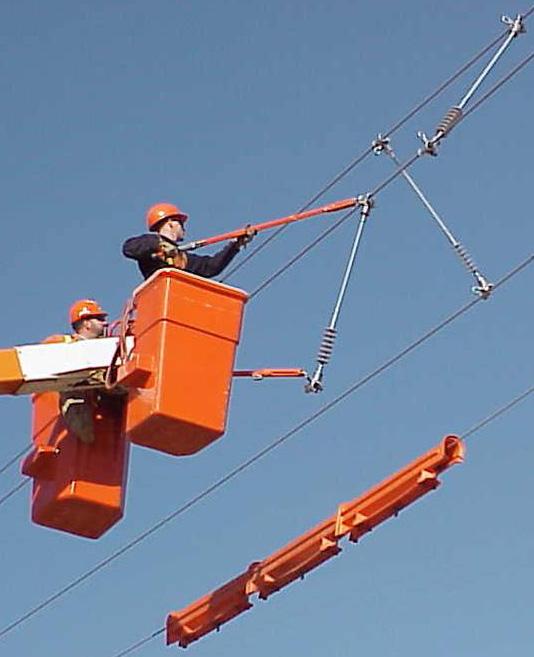
41 InterPhase Spacer installation from Helicopter using Barehand/Live Line work method Crossing InterPhase Spacer InterPhase Spacer installation InterPhase Spacer installation using Hot Line Tools 3
42 DISTRIBUTION INTERPHASE SPACER 15kV to 69kV ITEM SPECIFICATION DATA 1 OPERATING VOLTAGE (PHASE PHASE) kv 2 MOUNTING ARRANGEMENT: 1) HORIZONTAL 2) VERTICAL 3 LENGTH L (CONDUCTOR CONDUCTOR) mm 4 CONDUCTOR DIAMETER (INCLUDING ARMOUR ROD IF APPLICABLE) mm 5 CONDUCTOR CLAMP: 1) SUSPENSION 2) K-CLAMP 6 POLLUTION LEVEL (IEC 60815) 7 EYE NUT OPTION FOR LIVE LINE INSTALLATION (SEE DETAIL A ) YES NO NOTE: 1. OTHER DESIGNS ARE AVAILABLE, PLEASE CONTACT KLI FOR DETAILS. 2. ARMOR ROD MAY BE REQUIRED 4
43 SPECIAL APPLICATION DISTRIBUTION INTERPHASE SPACER 15kV to 69kV ITEM SPECIFICATION DATA 1 OPERATING VOLTAGE (PHASE PHASE) kv 2 MOUNTING ARRANGEMENT: 1) HORIZONTAL 2) VERTICAL 3 LENGTH L (CONDUCTOR CONDUCTOR) mm 4 CONDUCTOR DIAMETER (INCLUDING ARMOUR ROD IF APPLICABLE) mm 5 CONDUCTOR CLAMP: 1) ADJUSTABLE K-CLAMP 6 POLLUTION LEVEL (IEC 60815) 7 EYE NUT OPTION FOR LIVE LINE INSTALLATION (SEE DETAIL A ) YES NO NOTE: 1. OTHER DESIGNS ARE AVAILABLE, PLEASE CONTACT KLI FOR DETAILS. 2. THIS DESIGN IS INTENDED FOR SHORT SPANS AND TO ASSIST IN CONTROLLING LOW SEVERITY CONDUCTOR MOTION. 3. ARMOR ROD MAY BE REQUIRED. 5
44 TRANSMISSION INTERPHASE SPACER 69kV to 400kV ITEM SPECIFICATION DATA 1 OPERATING VOLTAGE (PHASE PHASE) kv 2 MOUNTING ARRANGEMENT: 1) HORIZONTAL 2) VERTICAL 3 LENGTH L (CONDUCTOR CONDUCTOR) mm 4 CONDUCTOR DIAMETER (INCLUDING ARMOUR ROD IF APPLICABLE) mm 5 CONDUCTOR CLAMP: 1) SUSPENSION 6 POLLUTION LEVEL (IEC 60815) NOTE: 1. OTHER DESIGNS ARE AVAILABLE, PLEASE CONTACT KLI FOR DETAILS. 2. ARMOR ROD MAY BE REQUIRED. K-LINE INSULATORS LIMITED 50 Passmore Avenue, Toronto, Ontario, Canada M1V 4T1 Tel.: (416) Fax: (416) insulators@k-line.net Web Page: April


45 K-LINE INSULATORS LIMITED TORONTO, ONTARIO, CANADA Catalogue D-RS DISTRIBUTION SILICONE INSULATORS Riser Support 15 kv to 69 kv ISO9001 GLOBAL FILE No
46 Distribution Silicone Insulators Riser Support On distribution overhead lines there are numerous tap-offs from the main line to provide connections to equipment (e.g., transformers, switches, fuses, underground cables, etc.) or lines (e.g., services, junctions, etc.). Normally leads are used to connect the equipment or line to the main line. These leads can be long and difficult or hazardous to operate. The use of riser support insulators can provide a safe and economical support for these leads. K-LINE INSULATORS LIMITED (KLI) silicone riser support insulators are manufactured and tested to world-class polymer insulator standards, CSA, ANSI and IEC. K-LINE INSULATORS LIMITED is registered to ISO 9001 Quality Systems. APPLICATION Distribution riser support insulators are used on distribution lines operating at or below 69 kv. These insulators are installed on metal, concrete or wooden structures, standoff brackets and cross arms to hold and insulate conductor leads. CORE ROD The core rod of the insulator is made of a high quality, epoxy resin, E-Glass fiberglass rod that has been specially formulated for electrical and mechanical applications. HOUSING The housing (includes sheath and sheds) of the insulator is one piece, high temperature vulcanized, injection molded silicone rubber that is chemically bonded to the core rod. This ensures that the interface between the rubber and rod is impenetrable against moisture ingress. KLI uses its own proprietary silicone rubber formula in the manufacture of its insulators. The formulation has silicone rubber as the base polymer material with additives to enhance its performance in wet and contaminated environments. FITTINGS The riser insulator comes standard with a clamp to hold the conductor and a threaded base for mounting to apparatus. Conductor Clamp The clamp is an aluminum clamp that can accommodate copper or aluminum conductors # 6 AWG (0.20 ) to kcmil (0.95 ). Threaded Base The base is typically threaded for ⅝ -11, ¾ -10, M16x2, or M20x2.5 galvanized bolt. For other special clamp features or base threads please contact KLI. 2
47 DISTRIBUTION RISER SUPPORT INSULATORS TECHNICAL DATA SPECIFICATIONS UNIT CATALOGUE NUMBER** KL15ARSIU KL28ARSIU KL35SRSIU KL46SRSIU KL69HRSIU16 Voltage Class kv Section Length L mm (in) 370 (14.6) 480 (18.9) 534 (21.0) 600 (23.6) 766 (30.2) Dry Arcing Distance mm (in) 193 (7.6) 290 (11.4) 348 (13.7) 419 (16.5) 627 (24.7) Leakage Distance mm (in) 384 (15.1) 590 (23.2) 750 (29.5) 988 (38.9) 1798 (70.8) Low-Frequency Flashover Dry kv Wet kv Critical Impulse Flashover (Pos.) kv Radio Influence Voltage (RIV) at 1 MHz Test kv Max. V Below 1 Below 1 Below 3 Below Specified Cantilever Load (SCL) kn (lb) 1.7 (381) 1.2 (270) 1.1 (237) 0.9 (205) 0.7 (155) Max. Design Cantilever Load (MDCL) kn (lb) 0.42 (95) 0.27 (60) 0.20 (45) 0.15 (35) 0.09 (20) Approx. Weight kg (lb) 0.7 (1.5) 0.9 (1.9) 2.1 (4.7) 2.2 (4.8) 2.3 (5.1) Standard Packaging ** Options: For 5/8 tapped hole add X, for M16 add M16, or for M20 add M20 and for tin-plated clamp add D to the catalogue number. K-LINE INSULATORS LIMITED 50 Passmore Avenue, Toronto, Ontario, Canada M1V 4T1 Tel.: (416) Fax: (416) insulators@k-line.net Web Page: October
48 Standoff Brackets for Line Post Insulators Material: Galvanized Steel KLI PART No. A mm (in) B mm (in) C mm (in) D mm (in) STUD HOLE in TOP MTG. HOLE mm (in) BOTTOM MTG. SLOT in No. OF BOTTOM MTG. HOLE KLOP (3) 255 (10) 102 (4) 10 (0.38) 13/16 21 (0.81) 0.81x KLOP-HWBK08 76 (3) 255/305 (10/12) 102 (4) 10 (0.38) 13/16 21 (0.81) 0.81x KLMP-BK03 76 (3) 255/305 (10/12) 127 (5) 13 (0.50) 15/16 21 (0.81) 0.81x KLOP (9) 255 (10) 102 (4) 10 (0.38) 13/16 21 (0.81) 0.81x KLMP-BK (9) 305 (12) 127 (5) 13 (0.50) 15/16 23 (0.90) 0.90x KLOP-GB (18) 255 (10) 102 (4) 10 (0.38) 13/16 21 (0.81) 0.81x K-LINE INSULATOR LIMITED 50 Passmore Avenue, Toronto, Ontario, Canada M1V 4T1 Tel.: (416) Fax: (416) insulators@k-line.net Web Page: March 2016
49 Trunnion Clamp for Line Post Insulators K-LINE INSULATOR LIMITED 50 Passmore Avenue, Toronto, Ontario, Canada M1V 4T1 Tel.: (416) Fax: (416) Web Page: April 2017
50 Studs for Line Post Insulators LONG STUD TABLE 1 KLI Part No. D1 D2 L 1 L 2 T Washer Size KLOP032B 3/4-10UNC 5/8-11 UNC /4 x 2-1/4 KLOP032 3/4-10 UNC 5/8-11 UNC /2 2 x 2 KLOP153 3/4-10 UNC 3/4-10 UNC 1 7-1/ /4 x 2-1/4 KLOP032E 3/4-10 UNC 3/4-10 UNC x 3 KLOP032C 3/4-10 UNC 3/4-10 UNC 1 7-1/2 4 3 x 3 KLOP-HWBP03 7/8-9 UNC 3/4-10 UNC 1-1/4 7-1/2 4 3 x 3 KLOP032D 7/8-9 UNC 7/8-9 UNC 1-1/ x 3 Note: Item KLOP032 has a hex nylock nut. SHORT STUD TABLE 2 KLI Part No. D1 D2 L 1 L 2 KLOP027 3/4-10 UNC 3/4-10 UNC 1 2-1/4 KLOP027A 3/4-10 UNC 3/4-10 UNC 1 2-1/2 KLOP027B 7/8-9 UNC 7/8-9 UNC 1-1/4 3-1/2 Material: Steel, Hot Dipped Galvanized. Dimension: L 1, L 2 & T are approximate. K-LINE INSULATOR LIMITED 50 Passmore Avenue, Toronto, Ontario, Canada M1V 4T1 Tel.: (416) Fax: (416) insulators@k-line.net Web Page: March 2016

51 K-LINE INSULATORS LIMITED Catalogue: Hardware SCORPION Neutral Conductor Clamp Keeper Body Spurs Longitudinal Load Transversal Load 6.85" Vertical Load 3.25" Longitudinal Load Transversal Load Ø0.72" Vertical Load 3.75" 4.70" Stinger Eye The SCORPION Neutral Conductor Clamp was developed specifically to address the expressed needs of Customers using a wide range of Neutral Conductor sizes, including large diameter conductors. The Galvanized Iron SCORPION was designed to accommodate Conductor sizes from #4 AWG to 715 kcmil. The Stinger Eye has a 0.72 diameter hole for temporary support of Conductor Stringing Rollers during line construction. The Stinger Eye also serves as a permanent attachment point for an Overhead Secondary Service Tap. The SCORPION is supplied with a Round Washer and Lock Washer, Spurs or no Spurs and installed with Customer supplied ¾ Bolt Hardware. FEATURES: Material: Ductile Iron, Hot Dip Galvanized. Mounting Spurs for Wood Pole. No Spurs for Steel, Concrete, and Composite Poles. Conductor Range: 0.20 (#4 AWG) to 0.98 (715 kcmil AAC) Maximum Line Angle: 15º Stinger Eye: For the attachment of a Stringing Roller during conductor installation or Secondary Service Tap. Pole Mounting: The SCORPION is shipped with one ¾ flat round washer (max. 2 OD and min thick) and one ¾ lock washer. The bolt and nut are customer supplied at appropriate length. The installation torque for the ¾ -10 UNC bolt and nut is 130 ftlbs. ISO9001 SAI GLOBAL FILE No
52 CLAMPS Catalogue Number Mounting Spurs Body Tapped Weight per Unit Standard Packaging KLOP-HWCP08-A KLOP-HWCP08-B Yes No ¾ -10 UNC Bolt 4.5 lbs. 12 Units per box MAXIMUM DESIGN LOADS Loads supported by Neutral Clamp (Body and Keeper) Loads supported by Neutral Clamp Stinger Eye Maximum Design Loads kn (lbs) Maximum Design Slip Load (MDSL) for a dia. conductor 5.5 (1,250) Maximum Design Transversal Load (MDTL) on Keeper 10.0 (2,250) Maximum Design Transversal Load (MDTL) on Body 13.0 (2,900) Maximum Design Vertical Load (MDVL) 13.0 (2,900) Maximum Design Transversal Load (MDTL) 11.0 (2,500) Maximum Design Vertical Load (MDVL) 12.5 (2,800) NOTES: The MAXIMUM DESIGN LOADS are allowable loads The Loads are independent K-LINE INSULATORS LIMITED 50 Passmore Avenue, Toronto, Ontario, Canada M1V 4T1 Tel.: (416) Fax: (416) insulators@k-line.net Web Page: October 2013

53 K-LINE INSULATORS LIMITED TORONTO, ONTARIO, CANADA Catalogue MB-PT Single Circuit Pole Top Framing Assembly ISO9001 SAI GLOBAL FILE No
54 Single Circuit Pole Top Framing Assembly The ultimate in labour savings and convenience is provided by K-Line Insulators Limited s single circuit pole-top framing assembly. The assembly comes complete in kit form with mounting bracket, polymer line post insulators, trunnion clamps or K-Clamp and insulator mounting studs. Install with two bolts and the structure is ready to go. This assembly provides increased clearance for work methods, wildlife outages and clearance above ground. The hot dip galvanized steel brackets come with predrilled holes for mounting of riser support insulators and a grounding lug. The insulators are of silicone, the ultimate in polymer line post insulators for maintenance-free operation 2
55 Single Circuit Pole Top Framing Assembly SPECIFICATIONS TECHNICAL DATA UNITS CATALOGUE NUMBER KL15SCFKK KL28SCFKK KL35SCFKK KL46SCFKK Voltage Class kv Critical Impulse Flashover (Pos.) kv Dry Arcing Distance mm (in) 193 (7.6) 290 (11.4) 348 (13.7) 627 (24.7) Leakage Distance mm (in) 275 (10.8) 425 (16.7) 660 (26.0) 865 (34.0) Low-Frequency Wet Flashover kv DIMENSION A mm (in) 1168 (46) 1270 (50) 1422 (56) 1575 (62) DIMENSION B mm (in) 915 (36) 980 (40) 1087 (44) 1197 (48) VERTICAL LOAD RATING kn (lb) 5.3 (1200) 5.3 (1200) 5.3 (1200) 5.3 (1200) LONGITUDINAL LOAD RATING kn (lb) 5.3 (1200) 5.3 (1200) 5.3 (1200) 5.3 (1200) TRANSVERSE LOAD RATING kn (lb) 11.0 (2500) 11.0 (2500) 11.0 (2500) 11.0 (2500) TENSION LOAD RATING kn (lb) 11.0 (2500) 11.0 (2500) 11.0 (2500) 11.0 (2500) APPROXIMATE WEIGHT kg (lb) 27 (59) 28 (61) 30 (66) 32 (70) The loads are independent design loads Ordering Information The Single Circuit Pole Top Framing Assemblies are available with K-Clamps or Vertical & Horizontal trunnions with conductor clamps. CL DATAK-LINE INSULATORS LIMITED IMITED K-LINE ISULATORS L 50 Passmore Avenue, Toronto, Ontario, Canada M1V 4T1 Tel.: (416) Fax: (416) insulators@k-line.net Web Page: October
56 K-LINE INSULATORS LIMITED TORONTO, ONTARIO, CANADA Catalogue D-TIF Totally Insulated Framing System (TIF) 3-Phase TIF Tri-Frame - Distribution 15kV - 69kV (Patent Pending) ISO9001 SAI GLOBAL FILE No. 0001
57 3-Phase TIF Tri-Frame - Distribution Totally Insulated Framing System (Patent Pending) Generally Insulators are used to support electrical conductors on Overhead Distribution and Sub- Transmission systems to prevent line to ground contact. Conductors may be attached to Deadend/Suspension Insulators and suspended from Crossarms or supported on Line Post/Pin Insulators on Crossarms or Side Post Brackets. Conventional Crossarms have service life limitations due to wood rot, steel corrosion or fiber reinforced polymer (FRP) deterioration. K-LINE INSULATORS LIMITED (KLI) is introducing the Totally Insulated Framing (TIF) Tri-Frame design for Distribution Lines for nominal voltages up to and including 69 kv. This innovative design reduces many common concerns and difficulties encountered with wood, steel or fiberglass Crossarms. K-LINE INSULATORS LIMITED (KLI) Totally Insulated Framing (TIF) Systems offer alternative line designs that increase service life, reduce installation labour costs, enhance system reliability and improves safety during installation. KLI TIF Systems are a new, cost effective approach for Line Design, Construction, Maintenance and Hardening of Distribution and Sub-Transmission Systems. The TIF Tri-Frame configuration for Distribution or Sub-Transmission Lines offers an integrated onepiece framing concept that forms a compact three phase framing. TIF Tri-Frames are delivered fully assembled in a one piece frame configuration for rapid installation by simply bolting the TIF Tri-Frame assembly to the pole. Patented K-CLAMP TM or conventional Line Post End Fittings can be supplied with TIF Tri-Frame designs. The TIF Tri-Frame provides required horizontal and vertical conductor spacing and clearances and is an alternative to typical single circuit Crossarm or Armless Construction Standards. TIF offers significant cost savings over conventional line construction practices due to reduced labour for installation of the TIF Tri-Frame. Installation is a simple matter of Bolting the TIF Tri- Frame to the Pole with two Bolts compared to conventional line design and construction practices which normally require installation of Crossarms/Braces or Pole Top/Side Post Brackets, Insulator Pins/Studs, Insulators and related hardware. Summary of TIF Feature/Advantages/Benefits: TIF Tri-Frame offers improved safety in application. Rapid installation reduces Lineman exposure time in energized work environment Improved system reliability with integrated KLI proprietary Silicone Rubber Insulators Corrosion resistant Aluminum Alloy End Fittings and Frame TIF eliminates Crossarm life limitations due to rot, hidden corrosion and fiberglass deterioration TIF is lightweight and can be transported by line crews into areas difficult to access and erected in place without heavy lifting equipment TIF avoids vandalism associated with glass and porcelain insulators Improved aesthetics and compact triangular appearance TIF Tri-Frame Insulator configuration discourages roosting thus minimizing the probability of wildlife contact issues. 2
58 3-Phase TIF - Distribution (Patent Pending) SPECIFICATIONS UNITS TECHNICAL DATA CATALOGUE NUMBER KL35TIF_ KL46TIF_ KL69PTIF_ KL69P1TIF_ Voltage Class kv Leakage mm (in) 660 (26) 860 (34) 1170 (46) 1525 (60) Critical Impulse Flashover (Pos.) kv Low-Frequency Wet Flashover kv * Dimension A (Approx.) mm (in) 1520 (60) 1730 (68) 1930 (76) 2235 (88) Dimension B (Approx.) mm (in) 1040 (41) 1210 (48) 1350 (53) 1550 (61) Vertical Design Load ** kn (lbs) 6.0 (1350) 6.0 (1350) 6.0 (1350) 5.5 (1240) Transverse Design Load ** kn (lbs) 5.5 (1240) 5.5 (1240) 5.5 (1240) 5.5 (1240) Weight (Approx.) kg (lbs) 37.2 (82.0) 40.3 (88.9) 44.0 (96.9) 50.5 (111.0) *The value shown is as per CSA. **Individual conductor loads NOTE: The selection of the appropriate TIF design model depends on the minimum insulation voltage design required. Additionally, the minimum phase spacing requirement must also be considered in selecting the TIF design model. Ordering Information The TIF Framing Assemblies are available with K-CLAMPS or Horizontal/Vertical Trunnions. Add suffix K for K-CLAMP or HV for Horizontal & Vertical Trunnions. Conductor Clamps are ordered separately. 3


 292-2008 Fax: (416)")

59 3-Phase TIF - Distribution Field Trial (Patent Pending) CL DATAK-LINE INSULATORS LIMITED K-LINE ISULATORS L IMIT 50 Passmore Avenue, Toronto, Ontario, Canada M1V 4T1 Tel.: (416) Fax: (416) insulators@k-line.net Web Page: April
Transmission Silicone Insulators Line Post 69 kv to 230 kv
 K-LINE INSULATORS LIMITED Catalogue T-LP Transmission Silicone Insulators Line Post 69 kv to 230 kv ISO9001 SAI GLOBAL FILE No. 000117 Transmission Silicone Insulators Line Post Today transmission lines
TRANSMISSION & DISTRIBUTION SILICONE INSULATORS InterPhase Spacers 15 kv to 400 kv
 K-LINE INSULATORS LIMITED Catalogue TD-IPS TORONTO, ONTARIO, CANADA TRANSMISSION & DISTRIBUTION SILICONE INSULATORS InterPhase Spacers 15 kv to 400 kv ISO9001 SAI GLOBAL FILE No. 000117 Transmission &
INSULATORS NEW. See page J-4 for more information.
 INSULATORS INSULATORS NEW Improved 23613 Dead End/Suspension Insulator Salisbury s Improved 23613 Dead End/Suspension Insulator has aluminum end fittings. These new end fittings create a lightweight product
Polymer Suspension Insulators 69kV to 765kV
 CATALOG Polymer Suspension Insulators 69kV to 765kV NGK Locke Polymer Insulators, Inc. Virginia Beach, Virginia, U.S.A. TABLE of CONTENTS Table of Contents... 1 Design Features... 2 Material... 2 Definition
Polymer Post Insulators for 46 to 500kV Applications
 CATALOG 142 Polymer Post Insulators for 46 to 500kV Applications NGK-Locke Polymer Insulators, Inc. Virginia Beach, Virginia, U.S.A. TABLE of CONTENTS Process and Design Features...2 Materials...3 Application
Polymer Station Post Insulators for 69 to 345 kv Applications
 CATALOG 143 Polymer for 69 to 34 kv Applications NGK-Locke Polymer Insulators, Inc. Virginia Beach, Virginia, U.S.A. TABLE of CONTENTS Polymer... 1 Application Guidelines for Polymer Station Posts (SP)...
GROUP A. Polymeric Insulators.
 GROUP A Polymeric Insulators PYUNGIL Bldg., 1475-10, Gwanyang 2-dong, Dongan-gu, Anyang-si, Gyeonggi-do, 431-808, Korea Tel : 82-31-420-6650~3 FAX : 82-31-424-7300 www.pyungil.com Silicone Railway
Veri*Lite Deadend, Suspension & Line Post Insulators for 15-69kV Applications
 Veri*Lite Deadend, Suspension & Line Post Insulators for 569kV Applications Section Warranty Material Hubbell Power Systems, Inc. warrants all products sold by it to be merchantable (as such term is defined
General Requirements. Technical Specifications for Insulators of Transmission Lines
 Islamic Republic of Iran Vice Presidency for Strategic Planning and Supervision General Technical Specification and Execution Procedures for Transmission and Subtransmission Networks Insulators of Transmission
CS type composite silicone insulators up to 750 kv overhead lines for all pollution of the atmosphere levels
 Climate test equipment. Allows to perform test in various temperature and humidity conditions. CS type composite silicone insulators up to overhead lines for all pollution of the atmosphere levels Insulators
Notes Changed note Date. 1 (A) Changed template 09 / 07 / 2008
 Changed template 09 / 07 / 2008") Revisions Notes Changed note Date 1 (A) Changed template 09 / 07 / 2008 2 Changed template. Clause 12.5.4.1 hot-rolled steel added. Clause 12.5.4.2, 12.5.2.4, 12.5.3.4, 12.5.4.4, 12.5.5.4, 12.5.6.4, 12.5.7.4
Revisions Notes Changed note Date 1 (A) Changed template 09 / 07 / 2008 2 Changed template. Clause 12.5.4.1 hot-rolled steel added. Clause 12.5.4.2, 12.5.2.4, 12.5.3.4, 12.5.4.4, 12.5.5.4, 12.5.6.4, 12.5.7.4
General Technical Specification and Execution Procedures for Transmission and Subtransmission Networks Substation Insulators (63 kv- 400 kv)
") Islamic Republic of Iran Vice Presidency for Strategic Planning and Supervision General Technical Specification and Execution Procedures for Transmission and Subtransmission Networks Substation Insulators
Islamic Republic of Iran Vice Presidency for Strategic Planning and Supervision General Technical Specification and Execution Procedures for Transmission and Subtransmission Networks Substation Insulators
Energy Division Insulators
 Energy Division http://energy.tycoelectronics.com Insulators R Insulators Tyco Electronics Energy Division covers a wide range of polymeric, hybrid and porcelain insulators. For decades all these products
Veri*Lite Silicone Rubber Line Post Insulators for 15-72kV Applications
 Section 2-2 Veri*Lite Silicone Rubber Line Post Insulators for 15-72kV Applications Warranty - Material Hubbell Power Systems, Inc. warrants all products sold by it to be merchantable (as such term is
United States Department of Agriculture Rural Development Rural Utilities Service. RUS Bulletin 1724E-220
 United States Department of Agriculture Rural Development Rural Utilities Service RUS Bulletin 1724E-220 SUBJECT: Procurement and Application Guide for Non-Ceramic Composite Insulators, Voltage Class 34.5
Composite insulators. Features. Sicat 8WL3068, 8WL3078 and 8WL3088 for overhead contact line systems. siemens.com/rail-electrification
 Composite insulators Sicat 8WL3068, 8WL3078 and 8WL3088 for overhead contact line systems siemens.com/rail-electrification The Sicat 8WL3068, 8WL3078 and 8WL3088 type silicone composite insulators in accordance
Suspension clamps. Contents. General Oscillating and trunnion type suspension clamps forged.. 3. Oscillating type suspension clamps cast...
 Contents General......................................... 2 Oscillating and trunnion type suspension clamps forged.. 3 Oscillating type suspension clamps cast............... 4 Envelope type suspension
FOREWORD SCOPE NORMATIVE REFERENCES DEFINITIONS REQUIREMENTS... 4
 INSULATORS VERTICAL & HORIZONTAL MOUNTING - SPECIFICATION Page 1 of 20 Table of Contents FOREWORD... 2 1. SCOPE... 2 2. NORMATIVE REFERENCES... 3 3. DEFINITIONS... 4 4. REQUIREMENTS... 4 4.1. SERVICE CONDITIONS...
GUJARAT ENERGY TRANSMISSION CORPORATION LTD. TECHNICAL SPECIFICATIONS
 GUJARAT ENERGY TRANSMISSION CORPORATION LTD. SARADAR PATEL VIDYUT BHAVAN, RACE COURSE, BARODA 390 007. TECHNICAL SPECIFICATIONS FOR 220, 132 & 66 COMPOSITE SOLIDCORE STATION POST INSULATORS GETCO/E/2,1,6
Composite Insulator Components
 Composite Insulator Components Composite insulator components A composite insulator is made of at least two insulating parts a core and housing. It is equipped with end fittings. Core. The core is the
 Cutouts and Fuse Links Equipment to protect against faults and over-current conditions on power distribution systems. Open-Type Cutouts Linkbreak Cutouts Loadbreak Cutouts Cutout-Arrester Combinations
INSULATORS. Industry photo: should be a the same image as larger industry photo. Either a different crop or different angle.
 Industry photo: should be a the same image as larger industry photo. Either a different crop or different angle. Human photo. Can be environmental/ documentaty style or portrait of engineer. industry photo.
TRANSMISSION NEW PROJECTS DEPARTMENT TRANSMISSION LINES TOWER DESIGN AND SPECIFICATIONS SECTION ATHENS - GREECE SPECIFICATION TR-1
 I NDEPENDE N T POWER TR ANSM ISSION OP ER AT O R S.A. TRANSMISSION NEW PROJECTS DEPARTMENT TRANSMISSION LINES TOWER DESIGN AND SPECIFICATIONS SECTION ATHENS - GREECE SPECIFICATION TR-1 STRING INSULATOR
33-SDMS-02 SPECIFICATIONS FOR
 SPECIFICATIONS FOR MV AUTOMATIC LINE SECTIONLIZER UP TO 36 KV This specification is property of SEC and subject to change or modification without any notice TABLE OF CONTENTS SECTION T I T L E PAGE NO.
Data Sheet 110kV TD123II dry type outdoor termination
 3 Data Sheet 110kV TD123II dry type outdoor termination 1. Product Description: 3M 110kV TD123II dry type outdoor termination meets requirement of test and product according to IEC60840 and GB11017.3,
30-SDMS-01 SPECIFICATIONS FOR LOAD BREAK SWITCH
 SPECIFICATIONS FOR LOAD BREAK SWITCH This specification is property of SEC and subject to change or modification without any notice TABLE OF CONTENTS 1.0 SCOPE 3 2.0 CROSS REFERENCES 3 3.0 APPLICABLE CODES
8. Hydrophobicity classification guide STRI guide 1.92/1 9. Radio interference characteristics of overhead power lines and high-voltage equipment
 Revised in Jan 14 TECHNICAL SPECIFICATION FOR 11KV POLYMER INSULATORS (C&T) 1.0. Scope This specification covers design, manufacture, testing and supply of composite insulators for use in the 11KV overhead
ENGINEERING SPECIFICATION EE SPEC
 /. Company Directive ENGINEERING SPECIFICATION EE SPEC : 84/1 Relating to Surge Arresters EE SPEC : 84/1 20 December 2013-1 of 7 - IMPLEMENTATION PLAN Introduction This document defines the surge arresters
NPS/001/008 Technical Specification for Gapless Metal Oxide Surge Arresters
 Version:- 5.0 Date of Issue:- October 2017 Page 1 of 18 NPS/001/008 Technical Specification for Gapless Metal Oxide Surge Arresters 1. Purpose The purpose of this document is to detail the technical requirements
Innovative New Live Line Tool and Framing Designs Facilitating Safe and Efficient Cross-arm Replacement
 Innovative New Live Line Tool and Framing Designs Facilitating Safe and Efficient Cross-arm Replacement A.J. Carreira, P.Eng., SMIEEE President Toronto, Canada carreira@k-line.net ISSUES WITH CURRENT CROSS
TEMPORARY PROTECTIVE GROUNDING EQUIPMENT
 TEMPORARY PROTECTIVE GROUNDING EQUIPMENT TEMPORARY PROTECTIVE GROUNDING EQUIPMENT NOTE: When ordeing assemblies of grounding products, please make sure all items included in the assembly are only from
ISO Rules Part 500, Facilities Division 502, Technical Requirements Section Bulk Transmission Technical Requirements
 Part 500, Facilities Division 502, Technical Requirements Section 502.2 Bulk Transmission Technical Requirements Applicability 1 This section 502.2 applies to: Requirements the legal owner of any bulk
Prototype Test Report ANSI C29.17 Quadri*Sil Line Post Insulators 2.5 Dia. Rod HPS Silicone rubber R
 PAGE: 1 Test Requests: R18-01-03 Report Number: R18-01-03 Prototype Test Report ANSI C29.17 Quadri*Sil Line Post Insulators 2.5 Dia. Rod HPS Silicone rubber R18-01-03 Introduction: Sample Quadri*Sil line
Technical Specification for Helical Fittings for Overhead Power Lines
 Ergon Energy Corporation Limited Technical Specification for Helical Fittings for Overhead Power Lines ETS01-09-03 Specification ETS01-09-03 Ver 3 Contents 1. Purpose and Scope... 4 2. References... 4
Power Systems 2 ELE3015. Lecture 1: Transmission Lines
 Power Systems 2 ELE3015 Lecture 1: Transmission Lines Transmission Lines: Introduction Use to carry electrical power from point of generation to the point of use. Usually over large distances. Made with
TEMPERED GLASS INSULATORS
 TEMPERED GLASS INSULATORS SUSPENSION-TYPE» Non-conducing support composed of an insulating glass piece and iron fittings allowing other units to be connected in series. A fastening iron fitting is included
SPECIFICATION FOR 11 & 33kV COMPOSITE INSULATORS Part 1: Pin Type
 Doc. KPLC1/3CB/TSP/04/017/1 1 Page 1 of 7 TABLE OF CONTENTS 0.1 Circulation List 0.2 Amendment Record FOREWORD 1. SCOPE 2. REFERENCES 3. TERMS AND DEFINITIONS 4. REQUIREMENTS 5. TESTS AND INSPECTION 6.
HIGH VOLTAGE INSULATORS. By JP Holtzhausen. Glass. Bushings & hollow core insulators. Cap & pin insulators
 HIGH VOLTAGE INSULATORS By JP Holtzhausen The principal dielectric used on overhead power lines is air at atmospheric pressure. The air, surrounding the bare high voltage aluminium or steel- cored aluminium
11KV PORCELAIN INSULATORS AND FITTINGS
 REC Specification 3/1971 (Revised 1993) 11KV PORCELAIN INSULATORS AND FITTINGS FOREWORD This specification was originally issued in 1971 on the basis of the decisions taken in the First and Second Standardisation
Project: Type: Qty: Optics. Series. Reflector Mounting Lamping Finish Voltage Options BLC - S BLC-L 21 1 /4" 36 1 /4" 3 1 /2" O.D.
 Project: Type: Qty: Series Optics Mounting Lamping Finish Voltage Options Pole Series Finish Pole Options Series Optics Mounting Lamping Finish Voltage Options BLC Beta Lantern L S Flat Glass Lens Sagged
Data Sheet 110kV TP123-II Porcelain Insulator Outdoor Termination
 3 Data Sheet 110kV TP123-II Porcelain Insulator Outdoor Termination 1 Product Description 3M 110kV TP123-II termination meets requirements of IEC60840 and GB11017.3 standards. The porcelain insulator is
Polluted Outdoor Insulators Maintenance and Washing
 Polluted Outdoor Insulators Maintenance and Washing Ali Naderian, PhD, PEng, SM IEEE Toronto, Canada February 2018 ali.naderian@ieee.org 1 برگزار کنندگان ایکهربا سامانه تجهیزات صنعت برق ایران کارشناسان
IEEE T&D Insulators 101
 Insulators 101 Section A Introduction Presented by Andy Schwalm IEEE Chairman, Lightning and Insulator Subcommittee IEEE/PES 2010 Transmission and Distribution Conference and Exposition New Orleans, Louisiana
094: 2000 CEB STANDARD. MEDIUM VOLTAGE PIN INSULATORS & HARDWARE (12kV & 36 kv) CEYLON ELECTRICITY BOARD SRI LANKA
 CEYLON ELECTRICITY BOARD SRI LANKA") 094: 2000 CEB STANDARD MEDIUM VOLTAGE PIN INSULATORS & HARDWARE (12kV & 36 kv) CEYLON ELECTRICITY BOARD SRI LANKA Specification for MEDIUM VOLTAGE PIN INSULATORS & HARDWARE (12kV & 36 kv) CEB Standard
094: 2000 CEB STANDARD MEDIUM VOLTAGE PIN INSULATORS & HARDWARE (12kV & 36 kv) CEYLON ELECTRICITY BOARD SRI LANKA Specification for MEDIUM VOLTAGE PIN INSULATORS & HARDWARE (12kV & 36 kv) CEB Standard
ECONOMIC ANALYSIS OF 400 KV TRANSMISSION TOWERS WITH CROSS ARMS INSULATORS
 ECONOMIC ANALYSIS OF 400 KV TRANSMISSION TOWERS WITH CROSS ARMS INSULATORS Kumissay Saudeger Yildiz Technical University TURKEY Altug Bozkurt Yildiz Technical University TURKEY ABSTRACT For economic and
POST AND DISC INSULATOR
 POST AND DISC INSULATOR September 2017 Engineering Department WEST BENGAL STATE ELECTRICITY TRANSMISSION COMPANY LIMITED Regd. Office: VidyutBhawan, Block DJ, Sector-II, Bidhannagar, Kolkata 700091. CIN:
56-SDMS-01 REV. 01 SPECIFICATIONS FOR
 56-SDMS-01 REV. 01 SPECIFICATIONS FOR 13.8KV UNIT SUBSTATIONS This specification is property of SEC and subject to change or modification without any notice CONTENTS PAGE No. 1.0 SCOPE 3 2.0 CROSS REFERENCES
Unit Price Labor. INSTALL 138KV DISCONNECT SWITCH WITH MOTOR OPERATOR AND AUXILIARY SWITCHES ON EXISTING STRUCTURE 1 ea.
 SUBSTATION B UPGRADE CONSTRUCTION MAJOR MATERIAL NOTES: Contractor to fill in line item column "Est. Qty." for items left blank. Construction Unit No. Description Est. Qty. Unit Labor 100 INSTALL 138KV
Outdoor High Voltage Non-Ceramic Insulators
 Outdoor High Voltage Non-Ceramic Insulators V.P. Karthika 1, P. Anitha 2, A. Hearty Rugesh 3 1 Teaching Fellow, 2 Assistant Professor, 3 UG Student 1, 2, 3 Department of EEE, Anna University, Thoothukudi
Technical Specification for Outdoor Porcelain Station Post Insulators
 Ergon Energy Corporation Limited Technical Specification for Outdoor Porcelain ETS10-01-02 Specification ETS10-01-02 Ver 2 Contents 1. Purpose and Scope... 1 2. References... 1 2.1 Applicable Standards...
Why do Transmission Asset Owners Need a Transmission Restoration System (ERS)? Transmission Line Emergencies Do Occur
? Transmission Line Emergencies Do Occur") Sabotage of a critical 500 kv DC transmission line necessitated the erection of this Lindsey Emergency Restoration Structure. Total erection time was 5-1/2 hours. Why do Transmission Asset Owners Need
Sabotage of a critical 500 kv DC transmission line necessitated the erection of this Lindsey Emergency Restoration Structure. Total erection time was 5-1/2 hours. Why do Transmission Asset Owners Need
Details of technical leaflets/write-up on various pieces of equipment.
 Details of technical leaflets/write-up on various pieces of equipment. (1) Insulator Designs: The insulators are provided in one, two, three, or four insulator designs per location and spaced to provide
STANDARD TECHNIQUE : OH4L/1
 Company Directive STANDARD TECHNIQUE : OH4L/1 Relating to Stay Strands and Fittings for Overhead Lines ST:OH4L/1 March 2012-1 of 21 - Document Revision & Review Table Date Comments Author 06/06/13 Note
Series IEEE 1070 ERS
 Series IEEE 1070 ERS Quality and innovations in Q UESTION: WHY DO TRANSMISSION ASSET OWNERS NEED AN EMERGENCY RESTORATION SYSTEM (ERS)? A NSWER: Transmission line emergencies do occur. Whether caused by
Specification for Polymer Disc Insulator
 Specification for Polymer Disc Insulator Scope : This specification cover the design, manufacturing, testing at manufacturers works, transport to site, insurance, storage of 11 KV & 33 KV Polymer Disc
SPECIFICATION FOR POLYMER DISC INSULATOR
 SPECIFICATION FOR POLYMER DISC INSULATOR Scope : This specification cover the design, manufacturing, testing at manufacturers works, transport to site, insurance, unloading & storage of 11 KV & 33 KV Polymer
Index GROUNDING CONNECTORS. TYPE WB Ground Rod Clamps. TYPE G/SRC Ground Rod Clamps. Heavy-Duty Clamps. Standard-Duty Clamps (Universal)
") TYPE B Ground Rod Clamps Heavy-Duty Clamps GROUNDING CONNECTORS R30117 For direct burial. For connecting ground wire to driven rod. Designed to maintain proper alignment between ground wire and rod. Cast
TYPE B Ground Rod Clamps Heavy-Duty Clamps GROUNDING CONNECTORS R30117 For direct burial. For connecting ground wire to driven rod. Designed to maintain proper alignment between ground wire and rod. Cast
Daytona Beach Pier Building Renovation Jun 2010
 SECTION 15060 - HANGERS AND SUPPORTS PART 1 - GENERAL 1.1 RELATED DOCUMENTS A. Drawings and general provisions of the Contract, including General and Supplementary Conditions and Division 1 Specification
SECTION HANGERS AND SUPPORTS FOR PLUMBING
 SECTION 22 05 29 HANGERS AND SUPPORTS FOR PLUMBING PART 1 - GENERAL 1.1 RELATED DOCUMENTS A. Drawings and general provisions of the Contract, including General and Supplementary Conditions and Division
V. Design, Application, Maintenance & Operation Technical Requirements
 V. Design, Application, Maintenance & Operation Technical Requirements V.A PJM Design & Application of Overhead Transmission Lines 69 kv & Above These design criteria have been established to assure acceptable
056 : 1997 CEB STANDARD
 056 : 1997 CEB STANDARD CONDUCTOR AND INSULATOR HARDWARE FITTINGS FOR MEDIUM VOLTAGE OVERHEAD POWER LINES CEYLON ELECTRICITY BOARD SRI LANKA CEB STANDARD 056:1997 Specification for CONDUCTOR AND INSULATOR
12-SDMS-01 Rev.02 SPECIFICATIONS FOR
 12-SDMS-01 Rev.02 SPECIFICATIONS FOR CABLE JOINTS, TERMINATIONS, AND ACCESSORIES UP TO 36 KV This specification is property of SEC and is subject to change or modification without any notice. TABLE OF
COMPOSITE INSULATORS
 Maharashtra State Electricity Distribution Co. Ltd. SPECIFICATION NO.MSEDCL/ DIST: MM-III/07/2007 SPECIFICATION FOR 11 KV/22 KV/33 KV COMPOSITE INSULATORS 1 TECHNICAL SPECIFICATION FOR 11 KV/22 KV/33 KV
MASONRY ANCHORS AND CONNECTORS May 6, 2014
 Page - 1 This section includes specification text to assist in describing a variety of masonry anchors, connectors, and accessories intended for masonry construction. This document contains prepared master
SECTION OVERHEAD CONDUCTOR RAIL
 SECTION 34 23 06 OVERHEAD CONDUCTOR RAIL PART 1 - GENERAL 1.1 DESCRIPTION This Section describes and specifies the performance requirements to design, furnish, install, test, and place into satisfactory
Distributor Safety Bulletin HAZARD AWARENESS
 Distributor Safety Bulletin HAZARD AWARENESS Electrical Distribution Safety HAZARD DESCRIPTION K-Line Polymer Insulators: ESA has been made aware of K-Line Bulletin B06-01 and B06-03 addressing K-Line
PRY-MOULD. High Voltage Accessories for Extruded Cables
 PRY-MOULD High Voltage Accessories for Extruded Cables Linking the future As the worldwide leader in the cable industry, Prysmian Group believes in the effective, efficient and sustainable supply of energy
NPS/001/024 Technical Specification for Low Voltage Aerial Bundled Conductor Fittings
 Version:- 5.0 Date of Issue:- July 2017 Page 1 of 12 NPS/001/024 Technical Specification for Low Voltage Aerial Bundled Conductor Fittings 1. Purpose The purpose of this document is to outline the technical
New designed XLPE-insulated cables substituting paper-insulated pipe type cables
 MODERN CABLE SYSTEMS IN STEEL PIPES New designed XLPE-insulated cables substituting paper-insulated pipe type cables Volker AUE, Nexans Deutschland Industries, Germany, Volker.Aue@nexans.com Wilfried ROSEBROCK,
Hi-Tension News Spring/Summer Arresters. Introduction. Shield Wires EU1413-H
 Polymer Arresters as an Alternative to Shield Wire This article is taken from a paper presented at the 24th Annual Transmission & Substation Design and Operation Symposium. by Jim Sanders and Kevin Newman
HANGERS AND SUPPORTS FOR HVAC PIPING AND EQUIPMENT SECTION HANGERS AND SUPPORTS FOR HVAC PIPING AND EQUIPMENT
 13686.00 HANGERS AND SUPPORTS FOR HVAC PIPING AND EQUIPMENT 230529-1 SECTION 230529 - HANGERS AND SUPPORTS FOR HVAC PIPING AND EQUIPMENT 1.1 SUMMARY A. Section Includes: 1. Metal pipe hangers and supports.
NPS/003/015 Technical Specification for 33kV, 66kV and 132kV Post Insulators
 Version:- 3.1 Date of Issue:- June 2014 Page 1 of 13 NPS/003/015 Technical Specification for 33kV, 66kV and 132kV Post Insulators 1. Purpose This document is the technical specification for 33kV, 66kV
5 / 8" AFL NO. ULTIMATE STRENGTH (LBS.) APPROX. WEIGHT EACH (LBS.) APPLICATION SCE , HIBUS Double Suspension R1"
 APPROX. WEIGHT EACH (LBS.) APPLICATION SCE , HIBUS Double Suspension R1") Standard Clevis Eye (TYP.) C L C L 2 C L Hot Dip Galvanized Ductile Iron C L SCE--62-BC APPLICATION SCE--62 2,000. HIBUS Double Suspension NOTE: For Bolt, Nut and Cotter instead of Clevis Pin and Cotter,
Standard Clevis Eye (TYP.) C L C L 2 C L Hot Dip Galvanized Ductile Iron C L SCE--62-BC APPLICATION SCE--62 2,000. HIBUS Double Suspension NOTE: For Bolt, Nut and Cotter instead of Clevis Pin and Cotter,
Molded Product Catalog Revised: April A Marmon Wire & Cable / Berkshire Hathaway Company
 Molded Product Catalog Revised: April 2017 www.hendrixhpi.com A Marmon Wire & Cable / Berkshire Hathaway Company Hendrix Molded Products Division began with the development of HPI Tie Top Insulators in
SECTION CRL70 HEAVY GLASS TOP HUNG SLIDING DOOR SYSTEMS
 Page 1 of 6 SECTION 08 32 20 CRL70 HEAVY GLASS TOP HUNG SLIDING DOOR SYSTEMS USE THIS SECTION WHEN SPECIFYING OVERHEAD SUPPORTED GLASS [OR WOOD] PANEL PARTITIONS. SECTION INCLUDES OVERHEAD TRACK ASSEMBLY,
NEW Items. Wire Rope and Accessories. Eye Nuts, Bolts and Turnbuckles. Roller Chain. kent-automotive.com NI1
 In the digital version, you can navigate to each section by clicking on the page numbers. You can return to the Table of Contents by clicking in the header. Wire Rope and Accessories Wire Rope Commercial
E-Z-Ground Grounding Systems. Ground Wire Size. Water Pipe Size. 1/2 in /4 in. 2 in /2 in. 3-1/2 in TB
 Waterpipe Ground Clamps Cat. No. Ground Wire Size Water Pipe Size 2-TB 1/2 in., 3/4 in., 1 or rebar 4-10 3-TB 1-1/4 in., 1-1/2 in. or 2 in. #6, #4, 4 2-1/2 in., 3 in. or 3-1/2 in. #2 WG 5-TB 4 in., 4-1/2
SECTION VIBRATION AND SEISMIC CONTROLS FOR ELECTRICAL SYSTEMS
 PART 1 - GENERAL 1.1 RELATED DOCUMENTS A. Drawings and general provisions of the Contract, including General and Supplementary Conditions, apply to this Section. 1.2 SUMMARY A. This Section includes the
SECTION CHAIN-LINK FENCES AND GATES 02821/1
 SECTION 02821 - CHAIN-LINK FENCES AND GATES 02821/1 PART 1 - GENERAL 1.1 SUMMARY A. This Section includes the following: 1. Chain-Link Fences: 2. Gates: horizontal slide or swing. 3. Fences installed where
ASTM C857 A -16 AASHTO H -20 (for vaults beneath roadways) ASTM C857 A-8 (for vaults beneath incidental light truck traffic)
 ASTM C857 A-8 (for vaults beneath incidental light truck traffic)") 1 Scope This specification outlines the minimum requirements for 5i 7i (56I 84I) vaults to be used for three-phase sectionalizing cabinets and metering equipment. This specification applies to all 5i 7i
1 Scope This specification outlines the minimum requirements for 5i 7i (56I 84I) vaults to be used for three-phase sectionalizing cabinets and metering equipment. This specification applies to all 5i 7i
Easy assembly with standard tools. Fully insulated for direct mounting to steel panels. Threaded stud and
 1496-1497.qxp 12/16/2013 8:44 PM Page 1497 Cam-Lok J Series Connectors or NEMA 4 Cam-Lok J Series Connectors are specifically designed to meet the needs of demanding portable applications. J Series Plugs
Transmission Line General Requirements Including Typical Overhead Line Structures. Document Number: 1-03-FR-09
 Transmission Line General Requirements Including Typical Overhead Line Structures Document Number: 1-03-FR-09 VERSION 1.0 June 2018 This functional requirements document is in line with the organisation's
OVERHEAD SERVICES - SECONDARY
 OVERHEAD SERVICES - SECONDARY Contents - Overhead Services... O-1 General Requirements for Overhead Service... O-2 Names of Parts for Overhead Service... O-3 Service Attachment on an Unguyed Service Mast...
SECTION EZ-SLIDE 80 AND 180 HEAVY GLASS TOP HUNG SLIDING DOOR SYSTEMS
 Page 1 of 6 SECTION 08 32 20 EZ-SLIDE 80 AND 180 HEAVY GLASS TOP HUNG SLIDING DOOR SYSTEMS USE THIS SECTION WHEN SPECIFYING OVERHEAD SUPPORTED GLASS PANEL PARTITIONS. SECTION INCLUDES OVERHEAD TRACK ASSEMBLY,
Company Replaces previous document Document ID Issue E.ON Elnät Sverige AB Ny engelsk utgåva D
 Document type Page Verksamhetsstyrande 1 (5) Company Replaces previous document Document ID Issue E.ON Elnät Sverige AB Ny engelsk utgåva D17-0008968 1.0 Organisation Valid from Valid until Regionnätsaffärer
TS 804 CABLES TABLE OF CONTENTS TRAFFIC SIGNAL EQUIPMENT POLE WIRING DIAGRAM LOCATIONS WITH CENTRE MEDIANS
 TORONTO TRANSPORTATION January 2012 TS 804 CABLES TABLE OF CONTENTS 1. DRAWINGS TTD 804.001 TTD 804.002 TTD 804.003 TTD 804.005 TTD 804.006 TTD 804.007 TTD 804.010 TTD 804.015 TTD 804.020 TTD 804.025 TTD
NATIONAL ELECTRIC POWER COMPANY (NEPCO) TENDERNO. 9/2013 FOR THE SUPPLY OF INSULATORS AND FITTINGS FOR DOUBLE AND QUADRUPLE CIRCUITS 132 kv OHTL's
 TENDERNO. 9/2013 FOR THE SUPPLY OF INSULATORS AND FITTINGS FOR DOUBLE AND QUADRUPLE CIRCUITS 132 kv OHTL's") TENDERNO. 9/2013 7. TECHNICAL SPECIFICATION 7.A SCOPE: This specification covers the design, manufacture, testing, packing, supply, CFR delivery to Aqaba Docks in Jordan and guarantee (maintain) the following
TENDERNO. 9/2013 7. TECHNICAL SPECIFICATION 7.A SCOPE: This specification covers the design, manufacture, testing, packing, supply, CFR delivery to Aqaba Docks in Jordan and guarantee (maintain) the following
NEW! PUPI Fiberglass Transmission & H-frame Products
 NEW! PUPI Fiberglass Transmission & H-frame Products REV06-2013 PUPI Transmission and H-frame Products Everything that makes PUPI the leader in fiberglass distribution crossarms makes us the best choice
CONNECTOR S T U D S H E A R. Design for Composite Structural Action STUD SHEAR CONNECTOR APPLICATION
 S T U D S H E A R CONNECTOR STUD SHEAR CONNECTOR APPLICATION Design for Composite Structural Action Exterior ashlar-type masonry veneer, typically of clay brick or concrete block masonry, are commonly
APDRP SCHEME, WESCO. Technical Specification for 33KV Air Break Switch PART 1: SCOPE AND CONDITIONS
 PART 1: SCOPE AND CONDITIONS 1. SCOPE This specification covers the design, engineering, manufacture, testing, supply, delivery, off-loading and performance requirements of 33kV, 200 amp, triple pole Gang
FIJI ELECTRICITY AUTHORITY BIDDING DOCUMENT
 FIJI ELECTRICITY AUTHORITY BIDDING DOCUMENT MR 15/2018 PREFERRED SUPPLIER FOR 33KV INSULATORS i Section 1: Instructions to Bidders 1. Scope of Bid The Fiji Electricity Authority (hereinafter referred to
BIDDING DOCUMENT FOR. Supply of Galvanized Steel Tubular Poles, 11KV Polymer Insulators and ACSR Conductors under Saubhagya Scheme
 BIDDING DOCUMENT FOR Supply of Galvanized Steel Tubular Poles, 11KV Polymer Insulators and ACSR Conductors under Saubhagya Scheme TENDER IDENTIFICATION NOS: No.ACE(MM)Saubhagya/2018-19/01. MAIN CONTENTS
Brugg Cables High Voltage Accessories. Swiss solutions for independent applications.
 Brugg Cables High Voltage Accessories. Swiss solutions for independent applications. Fact Book High Voltage Accessories Brugg Cables Business Unit High Voltage Accessories Dr. Ruben Vogelsang Head of Product
1.2 ACTION AND INFORMATIONAL SUBMITTALS.1 Provide submittals in accordance with Section Submittal Procedures.
 BID OPPORTUNITY NO. 253-2011 PAGE 1 OF 7 PART 1 GENERAL 1.1 REFERENCES.1 American Society of Mechanical Engineers (ASME).1 ASME B31.1, Power Piping, B31.3 Process Piping, B31.9 Building Services Piping..2
Pins Insulator. Composite/Polymers Insulators
 Composite/Polymers Insulators Electric network in India operates under very harsh environments. Industrial pollution, marshy land, hilly and unfriendly terrain, extreme weather, coastal region etc. make
Project number 36B/61952/Ed2. Date of circulation Supersedes document 36B/231/MCR. Safety EMC Environment Quality assurance
 IEC/TC or SC: SC 36B Title of TC/SC: Insulators for overhead lines Also of interest to the following committees TC 11 Functions concerned: Project number 36B/61952/Ed2 Date of circulation 2004-03-19 Supersedes
TABLE OF CONTENTS. Page FOREWORD INTRODUCTION SCOPE NORMATIVE REFERENCES
 TITLE SPECIFICATION FOR STAYS AND REFERENCE DATE: PAGE: 1 REV 1 APRIL 2009 OF 16 TABLE OF CONTENTS Page FOREWORD...... 3 INTRODUCTION...... 4 1 SCOPE...... 4 2 NORMATIVE REFERENCES...... 4 3 DEFINITIONS