Evaluation of the Flow Characteristics in the Intake Structure and Pump Sumps Using Physical Model
|
|
|
- Louisa Carter
- 6 years ago
- Views:
Transcription
1 International Journal of Engineering Research and Technology. ISSN Volume 7, Number 1 (2014), pp International Research Publication House Evaluation of the Flow Characteristics in the Intake Structure and Pump Sumps Using Physical Model Essam A. Khalifa* Mostafa A. Abu-Zeid ** S. M. Abdel-Rahman*** Sami A. A. El-Shaikh *** *Associate Professor, National Water Research Center, ** Chairman of the Mechanical & Electrical Department, MWRI, Egypt, abuzeidm@link.net ***Mechanical & Electrical Research Institute, National Water Research Center, Ministry of Water Resources ABSTRACT This paper presents a case study on the use of CFD modeling to re-evaluate and modify the design of a large plant influent pump station. A sump is designed to provide adequate water supply to pumps installed in sump. It is also essential to design the sump to provide fairly uniform and swirl free flow to pumps. The Hydraulic Institute Standards specify general guidelines for the design of sumps and is based on extensive studies on variety of sumps [1]. In case the sump is designed as per the guidelines of HIS, it is ensured that the flow pattern will be relatively uniform and swirl free flow to pumps. However it is not always possible to follow guidelines of HIS due to site constraints and to ensure uniform and swirl free flow to pump. Investigation of sump is required prior to installing the pumps at site. In the present analysis, sump with a circular design is analyzed using latest computational analysis tools i.e., CFD tools. CFD study was carried out on initial sump geometry and initial CFD results were analyzed. Based on initial CFD results, final sump geometry is modified and its results are presented herein along with suggested geometrical modifications. Key words: Intake, vortices, pump sump, flow velocity, Swirl, pre-rotation INTRODUCTION The basic purpose of a pump intake is to supply water with uniform velocity at the entry of an impeller. The fluid flow in Pump intakes is rather complex involving expansions and turns together with fluid structure interactions [2]. It is essential to
2 80 Essam A. Khalifa et al ensure that the pumps operating in such pump intakes get smooth swirl free flow at their inlets. Proper intake design provides uniform swirl free flow to the pumps. Intakes of such pumps and the geometrical layout of the channel surrounding the pump bells are usually designed in an empirical fashion, relying on laboratory model studies and experiences with previous installations [3]. The Hydraulic Institute Standards specify general guidelines for the design of pump intakes. The site constraints usually call for a deviation from the Standards. It then, becomes essential to investigate the pump intake to ensure smooth flow over the entire flow range of the pumps and in all the combinations of the pumps. Traditional approach was to carry out sump model studies experimentally with a reduced scale model and applying Froude Similarity rules. Computational Fluid Dynamics (CFD) has recently come up as an alternative approach to investigate the complex fluid flow phenomenon in sumps [4]. It is rapidly becoming an important tool for analysis and design in hydraulic engineering. Hydraulic engineering encompasses a broad range of activity from flow in a river to design of structures to control and distribute/divert water for various purposes. These flow problems have features that are not commonly found in other applications. In the case of pump industry applications, CFD tools are important in view of analysis of the hydraulic passage of the pumps and sumps. For impeller inlet, CFD can help to improve the inlet flow distribution by proper designing / checking the quality of flow in pump sump [5]. In case of sumps, CFD analysis is used to investigate flow quality entering into the pump at various combinations of pumps in operation. The analysis is done at minimum water level with pumps running at duty point. The velocities in the sump are highest at minimum water level [6]. OBJECTIVE Any flow pattern which departs from the one of the steady uniform flow is not desirable. Phenomena that cannot be present to an excessive degree are submerged vortices, free surface vortices, excessive pre-swirl of flow entering the pump chambers, non uniform spatial distribution of velocity at the impeller eye, excessive variations in velocity and swirl with time and entrained air/gas bubbles.it is prudent to investigate the flow pattern in entire sump i.e., pump chambers, fore-bay and pump bell etc before its actual construction. Undesirable flow condition like non-uniform flow, hydraulic jump, air entrainment, swirl beyond acceptable limits, submerged vortex etc. could be revealed right in advance of actual construction at site. Undesirable flow conditions could be eliminated / reduced to minimum, by incorporating the necessary modifications in sump and their effectiveness could be ascertained by studying the flow under modified conditions. USE OF CFD The development of computational tools has helped in resolving some of the issues in Sump Model studies [7]. The experimental study calls for enormous time and there are some inherent limitations of experimental activity as the exact modeling of
3 Evaluation of the Flow Characteristics in the Intake Structure 81 Reynolds Number, Froude Number & Weber number is not possible on geometrically similar smaller models. As the CFD analysis can be carried out on prototype also, the issues related to in-accurate prediction of prototype flows from model studies using smaller size experimental models do not come into picture. CFD tools avoid physical modeling and testing every time. Better and faster design of sump and its analysis leads to shorter design cycles. The civil construction work at site can progress faster based on CFD results. Due to various constraints the model sump has to destroy after the sump model study and again will have to make it, if required in future for solving sump problem. But the data generated in the CFD analysis of the sump can be kept for future reference [8]. CFD analysis can be used to see parts of the system or phenomena happening within the system that would not otherwise be visible through experimental analysis. CFD gives a means of visualizing and enhanced understanding of the fluid flow and hence better insight of the flow in sump [9, 10, 11, and 12]. CASE STUDY In this sump water is supplied to the sump through the intake channels fig.1 shows the plan and 3D views of the sump geometry respectively. The pumping system consists of 3 nos. of BHMa 55 pumps with capacity of 4968 m3/hr for each pump, out of which 1 pump are in operation and other 2 are kept as a standby for one case. CFD analysis also carried out for all pumps are in operation. It was proposed to carry out CFD analysis of the sump to see its overall suitability and to modify the geometry, in view of flow quality, if required. The CFD analysis of the sump includes a part of pump intake channel, forebay, intake bar screens and pipe representing the pump etc. The flow study is carried out for various combinations of pumps running at duty point at minimum water level (Please refer fig.1 for nomenclature of pumps). The flow quality was not good for initial sump geometry. Several trails have been done to improve the flow quality. Results of the recommended geometry are presented herein. The flow study is done with under consideration that pumps working at minimum water level as the operation at minimum water level is considered to be worst. CFD ANALYSIS TOOLS CFD tools are currently used worldwide to get advance information on hydraulic performance of systems. For this analysis the latest version of ANSYS CFX 14.0 is used. The surface model of the sump geometry of is created using well known solid modeler Pro-Engineer Wildfire (Creo-1). The geometry (.iges form) is taken into ANSYS ICEM-CFD 14.0 software for good quality grid generation. This grid file is further taken into ANSYS CFX-Pre 14.0 for applying the suitable physics to the geometry. CFX-Solver and CFX-Post is used to solve and analyzing the results respectively.
4 82 Essam A. Khalifa et al BOUNDARY CONDITIONS In CFD analysis, solution depends upon the appropriate boundary conditions. The outer wall is considered as a surface through which no flow can pass and the velocity at the surface is zero. These walls are defined as walls with no slip. The inlet boundary condition is applied at the entry in terms of total mass flow that is entering into the sump. The boundary conditions at the outlets were specified in terms of mass flow / pressure boundary i.e., amongst all outlets any one of outlet is specified in terms of pressure boundary and remaining outlets is specified in terms of mass flow boundary. The free surface was treated as a surface with zero normal gradients of flow properties. This is applied in terms of symmetry boundary condition at the top. All the pipes representing the Pumps are thin surfaces and treated as walls with no slip. Since this sump is located in sea, hence side walls of inlet domain are considered walls with free slip.the outer circular surface of sump is considered as wall with no slip. The domain type is fluid domain with water as the flowing fluid in the domain. The standard κ-ε turbulence model is used for analysis. This is one of the most prominent turbulence models. The κ-ε model has been implemented in most general purpose CFD codes and is considered the industry standard model. It has proven to be stable and numerically robust. For general purpose simulations, the κ-ε model offers a good compromise in terms of accuracy and robustness. The turbulence model uses the scalable wall-function approach to improve robustness and accuracy when the near-wall mesh is very fine. The scalable wall functions allow solution on arbitrarily fine near wall grids, which is a significant improvement over standard wall functions. SOLVER SCHEME USED FOR SOLVER The advection scheme that is used is High resolution. In this scheme, the blend factor values vary throughout the domain based on the local solution field in order to enforce a boundedness criterion. This scheme is a higher order scheme and gives good results especially in the case of recirculation of flows. Mostly the solution is converged to 10-5 RMS level. The convergence of Mass and momentum is ensured in the solution. RESULTS & DISCUSSION CFD RESULTS OF INITIAL GEOMETRY The initial geometry is prepared as per drawings and given in Fig 1. The initial geometry is prepared as per drawings and given in Fig 1. Fig.1 shows the plan view and fig.1 shows the 3D view of the sump geometry. For the analysis some part of the common canal is consider. Pump house is nearly perpendicular to the common canal. In the original geometry there is a forebay in between common canal and the pump chambers. Flow direction is shown in the fig.1.in the original sump geometry there was a blocking wall of unequal height also consider for the analysis to see the effect of the wall. There is a screen at 4.5 m from the pump centerline. There are 3 pumps in this pump house which are modeled as a pipe with bell and column pipe.

5 Evaluation of the Flow Characteristics in the Intake Structure 83 Fig.1. Initial Sump Geometry used for CFD analysis; Plan View 3D View The corresponding grid structure for the initial sump geometry is shown in Fig 2. The generated mesh is unstructured hybrid tetrahedral mesh with Mostly tetrahedral elements.total nos. of nodes is approx.0.4 million in the sump. Fine tetra elements were used near the wall pump chambers to achieve good computational results. Fig.2. Surface Grid Plot of Initial Sump; Plan View 3D View COMBINATION OF TEST CASES Working X Stand-By Table (1)-The combination of pumps in operation & pumps kept in standby mode for test cases is as per. Pump P-1 P-2 P-3 Original-1 X X Original-2 X X Original-3 X X Original-4


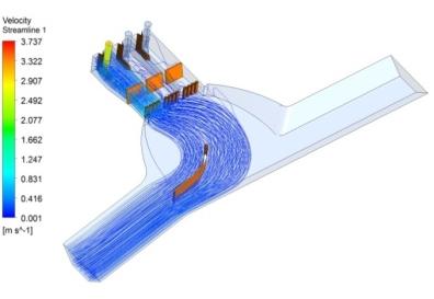
6 84 Essam A. Khalifa et al Modified-1 X X Modified-2 X X Modified-3 X X Modified-4 CFD RESULTS OF INITIAL SUMP GEOMETRY The qualitative results of CFD analysis of initial geometry for all combinations of test cases are presented in terms of streamline plots (Ref Fig 3.1 & 3.4). ORIGINAL-1 (P-1Working) Fig.3.1. Case 1 Pump 1 operate with Swirl Angles ; Plan View 3D View It is observed from the streamline plots of the sump geometry in fig.no.3.1 when P-1 is in operation and other pumps are in standby mode. It is observed that the flow is not getting distributed uniformly in the forebay. Large amount of recirculation zone and non-uniform flow in the pump chamber this may add to formation of swirl while flow enters in the bell. Due to this, flow pattern is almost un-symmetric in entire pump chamber. The swirl angle is found for this test case is which is much higher than the acceptable limit of 5 (As suggested in HIS). Hence sump geometry is not adequate for safe operation of pumps and sump. Thus for efficient and safe operation of pumps and sump, it is required to modify the sump geometry.


7 Evaluation of the Flow Characteristics in the Intake Structure 85 ORIGINAL-2 (P-2 Working) Fig. 3.2 Streamline plot for Case 2 Pump 2 operate with Swirl Angles ; Plan View 3D View It is observed from the streamline plots of the sump geometry in fig.no.3.2 when P-2 is in operation and other pumps are in standby mode. It is observed that the flow is not getting distributed uniformly in the forebay. Large amount of recirculation zone and non-uniform flow in the pump chamber this may add to formation of swirl while flow enters in the bell. The swirl angle is found for this test case is which is much higher than the acceptable limit of 5 (As suggested in HIS). ORIGINAL-3 (P-3 Working) Fig. 3.3 Streamline plot for Case 3 Pump 3 operate with Swirl Angles ; Plan View 3D View It is observed from the streamline plots of the sump geometry in fig.no.3.3 when P-3 is in operation and other pumps are in standby mode. It is observed that the flow is not getting distributed uniformly in the forebay. Large amount of recirculation zone and non-uniform flow in the pump chamber and especially behind and around the pump this may add to formation of swirl while flow enters in the bell. The swirl angle found is maximum for this case. Which is much higher than the acceptable limit of 5 (As suggested in HIS)?


8 86 Essam A. Khalifa et al ORIGINAL-4 (All Working) Fig. 3.4 Streamline plot for Case 4 All Pumps operate with Swirl Angles , , and respectively; Plan View 3D View It is observed from the streamline plots of the sump geometry in fig.no.3.4 when all pumps are in operation. It is observed that flow is not attached to the sidewalls of the forebay. Non-uniform flow recirculation zone and in the pump chamber and especially behind and around the pump this may add to formation of swirl while flow enters in the bell. The maximum swirl angle is found for this case. Which is much higher than the acceptable limit of 5 (As suggested in HIS)? As per the CFD results of the initial geometry for all test cases the quantitative results are given in the form of swirl angles in Table-2 it is found that the sump geometry is not adequate for safe operation of pumps and sump. Thus for efficient and safe operation of pumps and sump, it is required to modify the sump geometry. Table (2)-Swirl angle values for test cases of Initial sump geometry. Pump P-1 P-2 P-3 Original X X Original-2 X X Original-3 X X Original MODIFICATIONS IN INITIAL SUMP GEOMETRY CFD analysis of initial sump geometry was carried out and flow pattern is not found adequate. To have uniform flow entry in forebay and to reduce the recirculation zone in front of the corner pump chambers following geometrical modifications are done in the initial sump geometry for efficient and safe operation of pumps:- 1) Guide walls are placed at common channel to make the flow distribution uniform in all pump chambers. 2) Array of Flow Straightening Blocks is placed in the forebay to make the uniform flow distribution in the pump chamber.

.")
9 Evaluation of the Flow Characteristics in the Intake Structure 87 3) Floor and back wall splitters are added inside the pump chamber to avoid the recirculation of the flow behind and near the pumps. MODIFIED GEOMETRY The modified sump geometry is given in Fig 4. The corresponding grid structure for the modified sump geometry is shown in Fig 5. Fig.4. Modified Sump Geometry for CFD analysis; Plan View 3D View MODIFIED GEOMETRY MESH Fig.5.Surface Grid Plot of Modified Sump Geometry; Plan View 3D View CFD RESULTS OF MODIFIED SUMP GEOMETRY CFD analysis has been carried out for modified sump geometry. The qualitative results of CFD analysis of modified sump geometry are presented in terms of streamline plots (Fig 6.1 to 6.4 ).It is observed from the streamline plots of the sump geometry that flow pattern is almost uniformly distributed in entire pump chamber.

10 88 Essam A. Khalifa et al The modifications which are provided, ensures an equal distribution of the flow into the pump chamber. The recirculation zone is reduced to significant level and flow is entering uniformly into the suction bell of the pump. Some low velocity regions without any vortices are seen in front of the stand by pump chamber, which does not have significant contribution to the main flow. Also the strength of vortices formation at appropriate height of the pump is very low. The quantitative results are given in the form of swirl angles in Table-3. Swirl angles are measured at the appropriate locations in the pump. The table indicates that swirl angles are within acceptable limit acceptable limit of 5 (As suggested in HIS) for efficient operation of pumps/sump. Table (2)-Swirl angle values for test cases of Initial sump geometry. Pump P-1 P-2 P-3 Modified X X Modified-2 X X Modified-3 X X Modified MODIFIED-1 (P-1 Working) Fig.6.1. Streamline plot for Case 5 modified Case 1 with Swirl Angles ; Plan View 3D View It is observed from the streamline plots of the sump geometry in fig.no.6.1 when P-1 is in operation and other pumps are in standby mode that flow pattern is almost uniformly distributed in entire pump chamber. The modifications which are provided, ensures an equal distribution of the flow into the pump chamber. The recirculation zone is reduced to significant level and flow is entering uniformly into the suction bell of the pump. The swirl angle found is 2.29 for this case which is within the acceptable limit of 5 (As suggested in HIS).


. MODIFIED-3 (P-3 Working) Fig.6.3. Streamline plot for Case 7 modified Case 3 with Swirl Angles 0.")
11 Evaluation of the Flow Characteristics in the Intake Structure 89 MODIFIED-2 (P-2 Working) Fig.6.2. Streamline plot for Case 6 modified Case 2 with Swirl Angles ; Plan View 3D View It is observed from the streamline plots of the sump geometry in fig.no.6.2 when P-2 is in operation and other pumps are in standby mode that flow pattern is almost uniformly distributed in entire pump chamber. The modifications which are provided, ensures an equal distribution of the flow into the pump chamber. The recirculation zone is reduced to significant level and flow is entering uniformly into the suction bell of the pump. The swirl angle found is 0.25 for this case which is within the acceptable limit of 5 (As suggested in HIS). MODIFIED-3 (P-3 Working) Fig.6.3. Streamline plot for Case 7 modified Case 3 with Swirl Angles ; Plan View 3D View It is observed from the streamline plots of the sump geometry in fig.no.6.2 when P-2 is in operation and other pumps are in standby mode that flow pattern is almost uniformly distributed in entire pump chamber. The modifications which are provided, ensures an equal distribution of the flow into the pump chamber. The recirculation zone is reduced to significant level and flow is entering uniformly into the suction bell of the pump. The swirl angle found is 0.25 for this case which is within the acceptable limit of 5 (As suggested in HIS).
 analysis of the sump is carried out to confirm check the suitability of the sump.")
.")
12 90 Essam A. Khalifa et al MODIFIED-4 (All Working) Fig.6.4. Streamline plot for Case 8 modified Case 4 with Swirl Angles ; Plan View 3D View CONCLUSION The Computational Fluid dynamics (CFD) analysis of the sump is carried out to confirm check the suitability of the sump. It is observed from the streamline plots of the sump geometry that flow pattern is almost uniformly distributed in entire pump chambers due to appropriate geometrical modifications. Swirl angle is also within acceptable limit of 5 (As suggested in HIS). Geometrical modifications suggested are:- Guide wall in the forebay Array of flow straightner blocks Floor and back wall splitters Hence proposed sump geometry is recommended with the suggested geometrical modifications. REFERENCES [1] American National Standard for Pump Intake design (ANSI / HI ) by Hydraulic Institute, 9 Sylvan Way, Parsippany, New Jersey, USA. [2] Shazy A. Shabayek1, "Improving Approach Flow Hydraulics at Pump Intakes" International Journal of Civil & Environmental Engineering IJCEE-IJENS Vol: 10 No: 06, IJCEE, Nov. 10, [3] S.M. Borghei and A.R. Kabiri-Samani, "Effect of Anti-Vortex Plates on Critical Submergence at a Vertical Intake", Transaction A: Civil Engineering, Vol. 17, No. 2, pp. 89{95, c Sharif University of Technology, April [4] Shyam N. shukla, and J. T. Kshirsagar, "Numerical prediction of air entrainment in pump intakes", Proceedings of the Twenty-Fourth International Pump Users Symposium, [5] Khalifa, E.A. "Sensitivity Analysis of a Groundwater Flow Model" ASCE,
13 Evaluation of the Flow Characteristics in the Intake Structure 91 regional conference on environmental impacts on civil engineering technology. Cairo, Egypt, October 10-12, [6] Cecilia Lucino, Sergio Liscia y Gonzalo Duró, "Vortex Detection in Pump Sumps by Means of CFD", Xxiv Latin American Congress on Hydraulics Punta Del Este, Uruguay, (Iahr), November [7] ANSYS-CFX users guide, V. 14.0, By M/s ANSYS Inc., USA. [8] Tanweer S. Desmukh & V.K Gahlot, "Simulation of Flow through A Pump Sump and its Validation", IJRRAS 4 (1), July [9] Sami A. A. El-Shaikh, Enhancing Hydraulic Performance of Pump Intakes Using Computational Fluid Dynamics (CFD): Case Study, Water Science Journal, 2014 [10] Khalifa, E.A. "Groundwater Mathematical Model" is published in U.A.E. Japanese Workshop on "Water Resources and Greening in Desert" Abu Dhabi, January 28-29, [11] Abu-Zeid, M.A., The effect of Open Sump Intake on the Pump Performance, 11 th ICID International Drainage Workshop organized by Egyptian National Committee on Irrigation & Drainage (ENCID) & National Water Research Center (NWRC), [12] Abu-Zeid, M.A, Finite Element Analysis For Prediction Hydraulic Performance Of A Rectangular Flap Valve, International Journal of Engineering Research & Technology (IJERT)-International Research Publication House, 2013.
14 92 Essam A. Khalifa et al
nhc EARTH TECH CANADA INC. CITY OF WINNIPEG NORTH END WATER POLLUTION CONTROL CENTRE PUMP STATION MODEL TEST FINAL REPORT JANUARY 2005
 EARTH TECH CANADA INC. CITY OF WINNIPEG NORTH END WATER POLLUTION CONTROL CENTRE PUMP STATION MODEL TEST FINAL REPORT JANUARY 2005 nhc northwest hydraulic consultants CITY OF WINNIPEG NORTH END WATER POLLUTION
CFD Analysis of Pelton Runner
 International Journal of Scientific and Research Publications, Volume 4, Issue 8, August 2014 1 CFD Analysis of Pelton Runner Amod Panthee *, Hari Prasad Neopane **, Bhola Thapa ** * Turbine Testing Lab,
Lateral Outflow from Supercritical Channels
 Lateral Outflow from Supercritical Channels J. Coonrod 1, J. Ho 2 and N. Bernardo 3 1 Associate Professor, Department of Civil Engineering, University of New Mexico, Albuquerque, NM 87131; PH (505) 277-3233;
Heat transfer modelling of slot jet impinging on an inclined plate
 Heat transfer modelling of slot jet impinging on an inclined plate A. Ramezanpour 1, H. Shirvani 1 & I. Mirzaee 2 1 School of Design and Communication Systems, APU University, UK 2 CFD Research Centre,
Derivation of Global Parametric Performance of Mixed Flow Hydraulic Turbine Using CFD. Ruchi Khare, Vishnu Prasad and Sushil Kumar
 Derivation of Global Parametric Performance of Mixed Flow Hydraulic Turbine Using CFD Ruchi Khare, Vishnu Prasad and Sushil Kumar Ruchi Khare Vishnu Prasad Sushil Kumar Abstract: The testing of physical
CFD/FEM Based Analysis Framework for Wind Effects on Tall Buildings in Urban Areas
 2017 2nd International Conference on Industrial Aerodynamics (ICIA 2017) ISBN: 978-1-60595-481-3 CFD/FEM Based Analysis Framework for Wind Effects on Tall Buildings in Urban Areas Qiao Yan, Dalong Li,
CFD Analysis of a Low Head Propeller Turbine with Comparison to Experimental Data By: Artem Ivashchenko, Mechanical Solutions, Inc.
 CFD Analysis of a Low Head Propeller Turbine with Comparison to Experimental Data By: Artem Ivashchenko, Mechanical Solutions, Inc. Edward Bennett, Mechanical Solutions, Inc. CFD Analysis of a Low Head
Impellers of low specific speed centrifugal pump based on the draughting technology
 IOP Conference Series: Earth and Environmental Science Impellers of low specific speed centrifugal pump based on the draughting technology To cite this article: C Hongxun et al 2010 IOP Conf. Ser.: Earth
Hydraulic performance of a low specific speed centrifugal pump with Spanwise-Slotted Blades
 IOP Conference Series: Materials Science and Engineering OPEN ACCESS Hydraulic performance of a low specific speed centrifugal pump with Spanwise-Slotted Blades To cite this article: D X Ye et al 2013
CRHT VII. Design and CFD analysis of Pico- hydro Turgo turbine. Paper no. CRHT17-11
 Proceedings of the International Symposium on Current Research in Hydraulic Turbines CRHT VII April 04, 2016, Turbine Testing Lab, Kathmandu University, Dhulikhel, Nepal Paper no. CRHT17-11 Design and
Comparison between 2D and 3D Hydraulic Modelling Approaches for Simulation of Vertical Slot Fishways
 5 th International Symposium on Hydraulic Structures Brisbane, Australia, 25-27 June 2014 Hydraulic Structures and Society: Engineering Challenges and Extremes ISBN 9781742721156 - DOI: 10.14264/uql.2014.49
Numerical Investigation of the Combustion of Methane Air Mixture in Gas Turbine Can-Type Combustion Chamber
 International Journal of Scientific & Engineering Research, Volume 3, Issue 10, October-2012 1 Numerical Investigation of the Combustion of Methane Air Mixture in Gas Turbine Can-Type Combustion Chamber
Engineering & Expertise Designing Pump Sumps
 Engineering & Expertise Designing Pump Sumps Large submersible centrifugal pumps Engineering & Expertise Total solution engineering increases operational efficiency Introduction The proper design of the
ISSN No MIT Publications
 MIT International Journal of Mechanical Engineering Vol. 1 No. 2 Aug 2011, pp 93-100 93 CFD Analysis of 3-D Flow for Francis Turbine Manoj Kumar Shukla Lecturer, KNPC, Jabalpur (MP), India (Email: mksmact@gmail.com)
International Symposium on Current Research in HydraulicTurbines DESIGN AND CFD ANALYSIS OF PICO HYDRO TURGO TURBINE
 Kathmandu University International Symposium on Current Research in HydraulicTurbines (CRHT-VII) DESIGN AND CFD ANALYSIS OF PICO HYDRO TURGO TURBINE Sudish Gyanwali 1*, Kush Kuikel 1 and Abinath Thapa
New Developments in Design and Application of Long-Throated Flumes
 New Developments in Design and Application of Long-Throated Flumes Tony L. Wahl (1), John A. Replogle (2), Brian T. Wahlin (3), and James A. Higgs (4) (1) Hydraulic Engineer, U.S. Bureau of Reclamation,
CFD analysis of high speed Francis hydraulic turbines
 TRANSACTIONS OF THE INSTITUTE OF FLUID-FLOW MACHINERY No. 131, 2016, 111 120 Maciej Kaniecki a, Zbigniew Krzemianowski b CFD analysis of high speed Francis hydraulic turbines a Research and Development
Design and distribution of air nozzles in the biomass boiler assembly
 TRANSACTIONS OF THE INSTITUTE OF FLUID-FLOW MACHINERY No. 125, 2013, 13 28 KAROL RONEWICZ, TOMASZ TURZYŃSKI, DARIUSZ KARDAŚ Design and distribution of air nozzles in the biomass boiler assembly The Szewalski
Numerical Modelling of Air Distribution in the Natatorium Supported by the Experiment
 Proceedings of the World Congress on Mechanical, Chemical, and Material Engineering (MCM 2015) Barcelona, Spain July 20-21, 2015 Paper No. 277 Numerical Modelling of Air Distribution in the Natatorium
CFD modeling of airflows and contaminant transport in an aircraft cabin
 20th International Congress on Modelling and Simulation, Adelaide, Australia, 1 6 December 2013 www.mssanz.org.au/modsim2013 CFD modeling of airflows and contaminant transport in an aircraft cabin Jiuzhou
Flow simulation and efficiency hill chart prediction for a Propeller turbine
 IOP Conference Series: Earth and Environmental Science Flow simulation and efficiency hill chart prediction for a Propeller turbine To cite this article: T C Vu et al 2010 IOP Conf. Ser.: Earth Environ.
Introduction To Computational Fluid Dynamics. Presented by Marc Laing CFD Team Manager
 Introduction To Computational Fluid Dynamics Presented by Marc Laing CFD Team Manager Slide 1 50 years research in fluid and thermodynamics Flow meter calibration and development testing State-of-the-art
Heat Transfer Augmentation of Air Cooled Internal Combustion Engine Using Fins through Numerical Techniques
 Research Journal of Engineering Sciences ISSN 2278 9472 Heat Transfer Augmentation of Air Cooled Internal Combustion Engine Using Fins through Numerical Techniques Abstract Mishra A.K., Nawal S. and Thundil
Design of a Small Scale CFB Boiler Combustion Chamber for Laboratory Purposes
 International Journal of Emerging Engineering Research and Technology Volume 3, Issue 9, September, 2015, PP 1-7 ISSN 2349-4395 (Print) & ISSN 2349-4409 (Online) Design of a Small Scale CFB Boiler Combustion
Task 1 For Task 1, the outlet was set as a zero-gauge pressure outlet, which is the same outlet condition as the five smaller pipes.
 Jacob Schichtel Project 2 Page 1 of 9 Setup The geometry was created in ANSYS Design modeler as specified in the report instructions. A plane of symmetry was used to reduce the computation time and to
Computational Fluid Dynamic Analysis of Cross Flow Turbine
 Computational Fluid Dynamic Analysis of Cross Flow Turbine Mrudang Patel, Nirav Oza, Karna Patel U.G. Student, Department of Mechanical Engineering, NIRMA University, Ahmedabad, Gujarat, India ABSTRACT:
CFD on Small Flow Injection of Advanced Accumulator in APWR
 54 CFD on Small Flow Injection of Advanced Accumulator in APWR TOMOSHIGE TAKATA TAKAFUMI OGINO TAKASHI ISHIBASHI TADASHI SHIRAISHI The advanced accumulator in the advanced pressurized-water reactor is
Comparison Between PIV Measurements and CFD Simulation on a Model of GT Annular Burner
 Comparison Between PIV Measurements and CFD Simulation on a Model of GT Annular Burner D. Giordano, S. Giammartini, M. Rufoloni, G. Calchetti, F. Manfredi, E. Giacomazzi ENEA - C. R. Casaccia Sec. ENE-IMP
STUDY OF SHAPE OF INTERMEDIATE SILL ON THE DESIGN OF STILLING BASIN MODEL
 STUDY OF SHAPE OF INTERMEDIATE SILL ON THE DESIGN OF STILLING BASIN MODEL H. L. Tiwari 1, Avinash Panwar 2, Bharat Gehlot 3, Jalam Singh 4 1 Department of Civil Engineering, Maulana Azad National Institute
Aerodynamic Design of 2.5 MW Horizontal Wind Turbine Blade in Combination with CFD Analysis
 Aerodynamic Design of 2.5 MW Horizontal Wind Turbine Blade in Combination with CFD Analysis Seul-Ki Yeom *, Tae-Jin Kang *, Warn-Gyu Park 1) School of Mechanical Engineering, Pusan National University,
Design of Experiment Pressure Measurements Inside the Tokke Runner. * Corresponding author
 Proceedings of the International Symposium on Current Research in Hydraulic Turbines CRHT VI March 14, 2016, Turbine Testing Lab, Kathmandu University, Dhulikhel, Nepal Paper no. CRHT2016-16 Design of
COOLING EFFECT ENHANCEMENT IN MAGNETRON SPUTTERING SYSTEM
 Fifth International Conference on CFD in the Process Industries CSIRO, Melbourne, Australia 13-15 December 2006 COOLING EFFECT ENHANCEMENT IN MAGNETRON SPUTTERING SYSTEM Jae-Sang BAEK and Youn J. KIM*
A techno-economical view on energy losses at hydropower dams (case study of Karun III Dam and Hydropower Plant)
") Computational Methods in Multiphase Flow VI 253 A techno-economical view on energy losses at hydropower dams (case study of Karun III Dam and Hydropower Plant) M. Jorabloo 1, M. Abdolahpour 2, R. Roshan
Computational Methods in Multiphase Flow VI 253 A techno-economical view on energy losses at hydropower dams (case study of Karun III Dam and Hydropower Plant) M. Jorabloo 1, M. Abdolahpour 2, R. Roshan
NUMERICAL SIMULATION AND CFD ANALYSIS FOR ENERGY LOSS COMPUTATION IN FULLY OPEN GEOMETRY OF PELTON TURBINE NOZZLE
 International Journal of Latest Research in Science and Technology Volume2,Issue 1 :Page No.586-593,January-February (2013) http://www.mnkjournals.com/ijlrst.htm ISSN (Online):2278-5299 NUMERICAL SIMULATION
Design and Simulation of Very Low Head Axial Hydraulic Turbine with Variation of Swirl Velocity Criterion
 International Journal of Fluid Machinery and Systems DOI: http://dx.doi.org/10.5293/ijfms.2014.7.2.068 Vol. 7, No. 2, April-June 2014 ISSN (Online): 1882-9554 Original Paper (Invited) Design and Simulation
Flow Induced Vibration A Review of Current Assessment Methods
 Flow Induced Vibration A Review of Current Assessment Methods David Fielding, Matt Straw (Norton Straw Consultants) Alex Graham, Phil Shorter (CD-adapco) Introduction Presenting a joint study into flow-induced
ScienceDirect. CFD Analysis of a Kerosene Fuel Tank to Reduce Liquid Sloshing
 Available online at www.sciencedirect.com ScienceDirect Procedia Engineering 69 ( 2014 ) 1365 1371 24th DAAAM International Symposium on Intelligent Manufacturing and Automation, 2013 CFD Analysis of a
Performance improvement of headworks: a case of Kalignadaki A Hydropweor Project through physical hydraulic modelling
 Performance improvement of headworks: a case of Kalignadaki A Hydropweor Project through physical hydraulic modelling Dr. Ing. Meg B. Bishwakarma General Manager, Hydro Lab Pvt. Ltd., Nepal ABSTRACT: The
Computational Fluid Dynamics Based Investigation on Volute Geometry of Centrifugal Pump
 Computational Fluid Dynamics Based Investigation on Volute Geometry of Centrifugal Pump Arul Kumar.T Department Of Mechanical Engineering Sri Shakthi Institute Of Engineering And Technology, Coimbatore,
EXPERIMENTAL STUDY OF EFFECT OF END SILL ON STILLING BASIN PERFORMANCE
 EXPERIMENTAL STUDY OF EFFECT OF END SILL ON STILLING BASIN PERFORMANCE H.L.Tiwari Department of Civil Engineering, Maulana Azad National Institute of Technology, Bhopal, Madhya Pradesh INDIA Arun Goel
Modal Analysis as a Tool to Resolve Pump Vibration Issues
 Modal Analysis as a Tool to Resolve Pump Vibration Issues John Koch HDR, Bellevue, WA jkoch@hdrinc.com ABSTRACT Vibration spectrum analysis and modal analysis are tools designers and plant staff can use
Quenching steels with gas jet arrays
 Quenching steels with gas jet arrays PAUL F STRATTON ANDREW P RICHARDSON BOC Rother Valley Way, Holbrook, Sheffield UNITED KINGDOM Paul.stratton@boc.com http://www.catweb.boc.com Abstract: - Single components
THERMO-HYDRAULIC BEHAVIOUR OF COOLANT IN NUCLEAR REACTOR VVER-440 UNDER REFUELLING CONDITIONS
 Journal of MECHANICAL ENGINEERING Strojnícky časopis, VOL 67 (2017), NO 1, 87-92 THERMO-HYDRAULIC BEHAVIOUR OF COOLANT IN NUCLEAR REACTOR VVER-440 UNDER REFUELLING CONDITIONS PAULECH Juraj 1, KUTIŠ Vladimír
Comparison of RANS, URANS and LES in the Prediction of Airflow and Pollutant Dispersion
 Comparison of RANS, URANS and LES in the Prediction of Airflow and Pollutant Dispersion S. M. Salim, K. C. Ong, S. C. Cheah Abstract The performance of three different numerical techniques, i.e. RANS,
A CFD ANALYSIS OF CENTRIFUGAL PUMP TO IMPROVE DISCHARGE BY VARYING BLADE GEOMETRY
 A CFD ANALYSIS OF CENTRIFUGAL PUMP TO IMPROVE DISCHARGE BY VARYING BLADE GEOMETRY 1 ANJANI KUMAR SINHA, 2 A. JOHN RAJAN, 3 ERIKI ANANDA KUMAR 1,3 Senior Lecturer, Dept. of Mech. Eng., Nilai University,
Advanced Grit Removal Technology
 Advanced Grit Removal Technology Superior Performance Lowest Total Cost of Ownership Unequalled Experience Since pioneering the first flat-floor vortex grit removal system, S&L Engineering leads the water
Analysis of the corrosion test process for heat exchangers in corrosion test chambers by CFD simulation
 Analysis of the corrosion test process for heat exchangers in corrosion test chambers by CFD simulation STAR Global Conference, Wien, March 17-19, 2014 R. Stauch, F. Brändle, M. Pfitzer, W. Kühnel MAHLE
Development of hydraulic tanks by multi-phase CFD simulation
 Group M - Hydraulic Components Paper M-4 619 Development of hydraulic tanks by multi-phase CFD simulation Dipl.-Ing. Thees Vollmer Institute for Mobile Machines and Commercial Vehicles (IMN), Technische
FE ANALYSIS OF RUNNER BLADE FOR WELLS TURBINE
 Int. J. Mech. Eng. & Rob. Res. 2014 Kevin A Patel and Devendra A Patel, 2014 Research Paper ISSN 2278 0149 www.ijmerr.com Vol. 3, No. 3, July 2014 2014 IJMERR. All Rights Reserved FE ANALYSIS OF RUNNER
Heat Transfer Simulation of Impinging Jet with Finned Heat Sink
 Heat Transfer Simulation of Impinging Jet with Finned Heat Sink Shivakumar H 1, Krishnamurthy K N 2, Akashdeep B.N 3 Department of Thermal power Engineering, M.Tech student 1, Assistant professor 2, VTU
CFD Analysis of Domestic Centrifugal Pump for Performance Enhancement
 CFD Analysis of Domestic Centrifugal Pump for Performance Enhancement Satish M.Rajmane 1, Dr.S.P.Kallurkar 2. 1Research Scholar, WIT Research Center, Solapur University, Solapur, India (satishrajmane79@gmail.com)
BEHAVIOR OF REINFORCED CONCRETE BEAM WITH OPENING
 International Journal of Civil Engineering and Technology (IJCIET) Volume 8, Issue 7, July 2017, pp. 581 593, Article ID: IJCIET_08_07_062 Available online at http:// http://www.iaeme.com/ijciet/issues.asp?jtype=ijciet&vtype=8&itype=7
Hydraulics Laboratory Experiment Report
 Hydraulics Laboratory Experiment Report Name: Ahmed Essam Mansour Section: Title: "1", Monday 2-5 pm Centrifugal Pumps Date: 27 November, 2006 Objectives: To study the performance of a centrifugal pumps
Preliminary Study for Design Core of Nuclear Research Reactor of TRIGA Bandung Using Fuel Element Plate MTR
 Article Preliminary Study for Design Core of Nuclear Research Reactor of TRIGA Bandung Using Fuel Element Plate MTR Anwar Ilmar Ramadhan 1,3, *, Aryadi Suwono 1, Efrizon Umar 2, and Nathanael Panagung
Parametric Study for Evaluation of Design Parameters of Standing Column Well
 Proceedings World Geothermal Congress Bali, Indonesia, 5-9 April Parametric Study for Evaluation of Design Parameters of Standing Column Well Dong-Yeop Kwak 1, Duhee Park 1, Jae-Hoon Chang 1, Sang-Min
Abstract. Nomenclature. A Porosity function for momentum equations L Latent heat of melting (J/Kg) c Specific heat (J/kg-K) s Liquid fraction
 c Specific heat (J/kg-K) s Liquid fraction") Enthalpy Porosity Method for CFD Simulation of Natural Convection Phenomenon for Phase Change Problems in the Molten Pool and its Importance during Melting of Solids Abstract Priyanshu Goyal, Anu Dutta,
Enthalpy Porosity Method for CFD Simulation of Natural Convection Phenomenon for Phase Change Problems in the Molten Pool and its Importance during Melting of Solids Abstract Priyanshu Goyal, Anu Dutta,
Investigation of Rotating Instability in the Last Stage of Low Pressure Turbine during Low volume flow Operation
 Investigation of Rotating Instability in the Last Stage of Low Pressure Turbine during Low volume flow Operation Dilip Kumar Garg 1, Shrinivas Chambalwar 2, Jayant Sarode 3, Ajay Dhanopia 4 1 Department
Modeling Flow through a Lock Manifold Port
 Modeling Flow through a Lock Manifold Port by Richard L. Stockstill and E. Allen Hammack BACKGROUND: Manifolds are essential components of a navigation lock s filling and emptying system. They are used
Optimization of embedded Heat Exchanger in a flat plate Integrated Collector Storage Solar Water Heater (ICSSWH), with indirect heat withdrawal.
, with indirect heat withdrawal.") World Renewable Energy Congress (WRECX) Editor A. Sayigh 2008 WREC. All rights reserved. 1815 Optimization of embedded Heat Exchanger in a flat plate Integrated Collector Storage Solar Water Heater (ICSSWH),
World Renewable Energy Congress (WRECX) Editor A. Sayigh 2008 WREC. All rights reserved. 1815 Optimization of embedded Heat Exchanger in a flat plate Integrated Collector Storage Solar Water Heater (ICSSWH),
Study of Multiphase Flow at the Suction of Screw Compressor
 Purdue University Purdue e-pubs International Compressor Engineering Conference School of Mechanical Engineering 2014 Study of Multiphase Flow at the Suction of Screw Compressor Mohammad Arjeneh City University
CFD SIMULATION OF HEAVY GAS DISPERSION IN VENTILATED ROOMS AND VALIDATION BY TRACING EXPERIMENTS
 CFD SIMULATION OF HEAVY GAS DISPERSION IN VENTILATED ROOMS AND VALIDATION BY TRACING EXPERIMENTS L. Ricciardi, C. Prévost, L. Bouilloux, R. Sestier-Carlin Institut de Radioprotection et de Sûreté Nucléaire,
CFD Analysis of Clarifier Performance With and Without Energy Dissipating Inlet
 CFD Analysis of Clarifier Performance With and Without Energy Dissipating Inlet Figure 1: Energy Dissipating Inlet (LA-EDI) Introduction To estimate performance enhancements resulting from the use of an
MODELING OF DISPERSION AND DIFFUSION OF POLLUTANTS FROM INDUSTRIAL CHIMNEY STACKS IN RIJEKA REFINERY
 4th International Congress of Croatian Society of Mechanics September, 18-20, 2003 Bizovac, Croatia MODELING OF DISPERSION AND DIFFUSION OF POLLUTANTS FROM INDUSTRIAL CHIMNEY STACKS IN RIJEKA REFINERY
(b) Discuss in brief shaft spillway with neat sketches. Marks 04. OR Q (2) Explain in brief USBR stilling basin. Marks 08
 Discuss in brief shaft spillway with neat sketches. Marks 04. OR Q (2) Explain in brief USBR stilling basin. Marks 08") (b) Discuss in brief shaft spillway with neat sketches. Marks 04 OR Q (2) Explain in brief USBR stilling basin. Marks 08 Stilling Basins The basins are usually provided with special appurtenances including
(b) Discuss in brief shaft spillway with neat sketches. Marks 04 OR Q (2) Explain in brief USBR stilling basin. Marks 08 Stilling Basins The basins are usually provided with special appurtenances including
40-Ton Articulated Truck Cooling System Modelling Using STAR-CCM+
 40-Ton Articulated Truck Cooling System Modelling Using STAR-CCM+ Gary Yu, Martin Timmins and Mario Ciaffarafa DENSO Marston Ltd, Bradford, BD17 7JR, UK DENSO Marston Founded in 1904 Acquired by DENSO
Performance of an Open Ducted Type Very Low Head Cross- Flow Turbine
 Performance of an Open Ducted Type Very Low Head Cross- Flow Turbine Zhenmu Chen, Van Thanh Tien Nguyen, Morihito Inagaki, and Young-Do Choi * Abstract Cross Flow Turbine (CFT) known as a Banki turbine
Simulation of the Flow in a Packed-Bed with and without a Static Mixer by Using CFD Technique
 Simulation of the Flow in a Packed-Bed with and without a Static Mixer by Using CFD Technique Phavanee Narataruksa, Karn Pana-Suppamassadu, Sabaithip Tungkamani Rungrote Kokoo, and Prayut Jiamrittiwong
5 th OpenFOAM Workshop, Gothenburg, Sweden, June 21-24th, 2010 Using OpenFOAM for Tunnel Ventilation Design
 5 th OpenFOAM Workshop, Gothenburg, Sweden, June 21-24th, 2010 Using OpenFOAM for Tunnel Ventilation Design Jeannine Croll, 22/06/2010 ILF Group ILF Consulting Engineers The Company was established by
Urban Physics: towards sustainable buildings and cities
 Inauguration Event & Mini-Symposium for Prof.dr. Alexey Voinov: SYSTEMS AND SUSTAINABILITY IN TIME AND SPACE Urban Physics: towards sustainable buildings and cities Prof.dr.ir. Bert Blocken Eindhoven University
CFD Simulation Studies on Integrated Approach of Solar Chimney and Earth Air Tunnel Heat Exchanger for Building Space Conditioning
 International Journal of Economy, Energy and Environment 2017; 2(3): 32-39 http://www.sciencepublishinggroup.com/j/ijeee doi: 10.11648/j.ijeee.20170203.11 CFD Simulation Studies on Integrated Approach
Numerical Investigation of the Integration of Heat Transfer Devices into Wind Towers
 A publication of CHEMICAL ENGINEERING TRANSACTIONS VOL. 34, 2013 Guest Editors: Neven Duić, Petar Sabev Varbanov Copyright 2013, AIDIC Servizi S.r.l., ISBN 978-88-95608-25-9; ISSN 1974-9791 The Italian
Created by Simpo PDF Creator Pro (unregistered version) Asst.Prof.Dr. Jaafar S. Maatooq
 Asst.Prof.Dr. Jaafar S. Maatooq") Lect.No.9 2 nd Semester Barrages, Regulators, Dams 1 of 15 In order to harness the water potential of a river optimally, it is necessary to construct two types of hydraulic structures, as shown in Figure
Lect.No.9 2 nd Semester Barrages, Regulators, Dams 1 of 15 In order to harness the water potential of a river optimally, it is necessary to construct two types of hydraulic structures, as shown in Figure
Thermal Imaging for Discharge and Velocity Measurements in Open Channels. PKI 205C, Omaha, NE ;
 Thermal Imaging for Discharge and Velocity Measurements in Open Channels E. Jackson 1, D. Admiraal 2, D. Alexander 3, J. Stansbury 4, J. Guo 5, D. Rundquist 6, and M. Drain 7 1 Dept. of Electrical Engineering,
Limitations of Using Uniform Heat Flux Assumptions in Sizing Vertical Borehole Heat Exchanger Fields
 Limitations of Using Uniform Heat Flux Assumptions in Sizing Vertical Borehole Heat Exchanger Fields Veera Malayappan 1, Jeffrey D. Spitler 2 1,2 Mechanical and Aerospace Engineering, Oklahoma State University
CFD Analysis of Decay Heat Removal Scenarios of the Lead cooled ELSY reactor. Michael Böttcher
 CFD Analysis of Decay Heat Removal Scenarios of the Lead cooled ELSY reactor Michael Böttcher Institut für Neutronenphysik und Reaktortechnik (INR), Karlsruher Institut für Technologie, KIT Abstract In
ELBE RIVER MODEL: UVP FLOW MAPPING
 ELBE RIVER MODEL: UVP FLOW MAPPING Vojtech Bares 1 and Prof. Vojtech Broza 2 1 Doctorand, Czech Technical University in Prague, Faculty of Civil Engineering, Laboratory of Ecological Risks in Urban Drainage,
NUMERICAL MODEL FOR PREDICTION OF CRACKS IN CONCRETE STRUCTURES
 NUMERICAL MODEL FOR PREDICTION OF CRACKS IN CONCRETE STRUCTURES A. van Beek FEMMASSE B.V., Geldermalsen, The Netherlands B.E.J. Baetens INTRON B.V., Geldermalsen, The Netherlands E. Schlangen INTRON B.V.,
Design and Analysis of 3D Blades for Wells Turbine
 IJIRST International Journal for Innovative Research in Science & Technology Volume 1 Issue 11 April 2015 ISSN (online): 2349-6010 Design and Analysis of 3D Blades for Wells Turbine Shyjo Johnson Saintgits
Vortex Separator. May be more cost-effective pre-treatment devices than traditional wet or dry basins.
 Description Vortex separators: (alternatively, swirl concentrators) are gravity separators, and in principle are essentially wet vaults. The difference from wet vaults, however, is that the vortex separator
ANNUAL OF NAVIGATION 13/2008
 ANNUAL OF NAVIGATION 13/28 LUCJAN GUCMA, MARTA SCHOENEICH Maritime University of Szczecin JACEK JACHOWSKI Gdansk University of Technology CFD SHIP SQUAT DETERMINATION METHOD VALIDATION BY GPS-RTK MEASUREMENTS
Effect of Rotation Speed of a Rotary Thermal Wheel on Ventilation Supply Rates of Wind Tower System
 Available online at www.sciencedirect.com ScienceDirect Energy Procedia 75 (2015 ) 1705 1710 The 7 th International Conference on Applied Energy ICAE2015 Effect of Rotation Speed of a Rotary Thermal Wheel
October 20~ , Hohai University Nanjing, China 1 VORTEX SHAFT OUTLET. Naples Italy,
 October 20~23 2008, Hohai University Nanjing, China 1 VORTEX SHAFT OUTLET Giuseppe Del Giudice 1, Corrado Gisonni 2, Giacomo Rasulo 1 1 Department of Hydraulic and Environmental Engineering - University
THERMAL ANALYSIS OF CPU WITH VARIABLE BASEPLATE HEAT- SINK USING CFD
 THERMAL ANALYSIS OF CPU WITH VARIABLE BASEPLATE HEAT- SINK USING CFD Channamallikarjun Department of Mechanical Engineering, BKIT-Bhalki-585328 Abstract The computational fluid dynamics is concentrated
Computational study of Staggered and Double Cross Flow Heat Exchanger
 Defence Science Journal, Vol. 67, No. 4, July 2017, pp. 396-400, DOI : 10.14429/dsj.67.11427 2017, DESIDOC Computational study of Staggered and Double Cross Flow Heat Exchanger A.S. Krishnan * and P. Gowtham
Analysis of Shear Wall Transfer Beam Structure LEI KA HOU
 Analysis of Shear Wall Transfer Beam Structure by LEI KA HOU Final Year Project report submitted in partial fulfillment of the requirement of the Degree of Bachelor of Science in Civil Engineering 2013-2014
HYDRAULIC DEMONSTRATION CHANNEL
 HYDRAULIC DEMONSTRATION CHANNEL PACKING LIST Pitot-Static Tube and Manometer Tube Flow Meters 1. 48 Long Differential Manometer 2. Clear Tubing 3. Pitot-static Tube Clamp 4. Pitot-static Tube 1. Venturi
STUDY OF WATER DISTRIBUTION NETWORK USING EPANET
 STUDY OF WATER DISTRIBUTION NETWORK USING EPANET Darshan Mehta 1, Krunal Lakhani 2, Divy Patel 3, Govind Patel 4 Assistant Professor, Civil Engg. Dept., S.S.A.S.I.T, Surat, Gujarat, India 1 UG Student,
Investigation on pressure fluctuation in a Francis turbine with improvement measures
 IOP Conference Series: Earth and Environmental Science OPEN ACCESS Investigation on pressure fluctuation in a Francis turbine with improvement measures To cite this article: J J Feng et al 2014 IOP Conf.
Pumps, Turbines, and Pipe Networks. Ch 11 Young
 Pumps, Turbines, and Pipe Networks Ch 11 Young Chapter Topics Types of pumps and turbines Moment of momentum review Pump and turbine theory Energy and power Pump selection Pump-pipe networks Use of pipe
Minerals. WARMAN Centrifugal Slurry Pumps WBV Vertical Cantilever Slurry Sump Pump Series
 Minerals WARMAN Centrifugal Slurry Pumps WBV Vertical Cantilever Slurry Sump Pump Series The Warman WBV ultra heavy-duty range of vertical cantilevered slurry pumps sets a new industry benchmark for general
Prediction of Pollutant Emissions from Industrial Furnaces Using Large Eddy Simulation
 Paper # B03 Topic: Turbulent Flames 5 th US Combustion Meeting Organized by the Western States Section of the Combustion Institute and Hosted by the University of California at San Diego March 25-28, 2007.
Coal Pipe Coal Flow Distribution Control for Coal Pulverizer Systems
 Technical Publication Coal Pipe Coal Flow Distribution Control for Coal Pulverizer Systems by John Rath Engineer Pulverizer Engineering RILEY POWER INC. Jilin Zhang Engineer Fuel Equipment Design RILEY
Proceedings of the ASME nd International Conference on Ocean, Offshore and Arctic Engineering OMAE2013 June 9-14, 2013, Nantes, France
 Proceedings of the ASME 2013 32nd International Conference on Ocean, Offshore and Arctic Engineering OMAE2013 June 9-14, 2013, Nantes, France OMAE2013-10684 A COMPARISON STUDY OF PRESSURE VESSEL DESIGN
Agenda. Background Validation studies. 3D application. Co-simulation. Summary. Espedal stratified flow. StatOil wavy-slug flow.
 www.cd-adapco.com Computational Flow Assurance Recent progress in modelling of multiphase flows in long pipelines Simon Lo, Abderrahmane Fiala (presented by Demetris Clerides) Subsea Asia 2010 Agenda Background
Comparison of experimental results of horizontal kaplan turbine with computational fluid dynamics
 University of Iowa Iowa Research Online Theses and Dissertations Summer 2012 Comparison of experimental results of horizontal kaplan turbine with computational fluid dynamics Vijaya Bijukchhe University
Water Measurement. Presentation by. L. Niel Allen Extension Irrigation Specialist Utah State University
 Water Measurement Presentation by L. Niel Allen Extension Irrigation Specialist Utah State University to Utah State Engineer s Office Division of Water Rights Salt Lake City, Utah December 11, 2013 Introduction
Swansea Bay tidal powerplant: Bi-directional bulb pump-turbine with variable speed
 Swansea Bay tidal powerplant: Bi-directional bulb pump-turbine with variable speed M. Kragl, E. Kontoleontos, J. Michelcic, M. Case S. Weissenberger and B. Benz Tidal Lagoon Power Research and Development
FSI ANALYSIS OF TRAILING EDGE REGION COOLING IN HP STAGE TURBINE BLADE
 FSI ANALYSIS OF TRAILING EDGE REGION COOLING IN HP STAGE TURBINE BLADE Harishkumar Kamat Chandrakant R Kini Engineering,Manipal Institute of Technology, Engineering,Manipal Institute of Technology, N Yagnesh
Innovative Technology: Development and implementation of a self-cleaning wet-well
 Innovative Technology: Development and implementation of a self-cleaning wet-well Robert Domkowski Business Development Manager Municipal Market / Engineering Consultant Wastewater Workshop March 10, 2010