Created by Simpo PDF Creator Pro (unregistered version) Asst.Prof.Dr. Jaafar S. Maatooq
|
|
|
- Shanna Hunt
- 6 years ago
- Views:
Transcription


1 Lect.No.9 2 nd Semester Barrages, Regulators, Dams 1 of 15 In order to harness the water potential of a river optimally, it is necessary to construct two types of hydraulic structures, as shown in Figure 1. These are: 1. Storage structure : Usually a dam, which acts like a reservoir for storing excess runoff of a river during periods of high flows and releasing it according to a regulated schedule. 2. Diversion structure : which may be a weir or a barrage that raises the water level of the river slightly, not for creating storage, but for allowing the water to get diverted through a canal situated at one or either of its banks. The diverted water passed through the canal may be used for irrigation, industry, domestic water needs or power generation.
2 Lect.No.9 2 nd Semester Barrages, Regulators, Dams 2 of 15 1-Diversion Structures : 1-1 Barrages : A barrage, by definition, is a weir structure fitted with gates to regulate the water level in the pool behind in order to divert water through a canal for irrigation, power generation, and flow augmentation to another river. The barrages may be classified as being located in the following four types of river regimes: - Mountainous and sub-mountainous. - Alluvial and deltaic. The barrages constructed in these different types of rivers have their own advantages and disadvantages, as discussed below: * Advantages - The mountainous and sub-mountainous regions ; are suitable for locating a diversion structure for hydroelectric power schemes due to the availability of high heads and less siltation problems. For power canals (usually called power channels) the difference in elevations can be effectively utilized by generating hydro-power. - The disadvantageous of a large number of drops For the canal taking off from the barrage located in the mountainous and sub-mountainous regions, but it give a beneficial if it employment with a hydro-electric power generating units. * Disadvantages - For irrigation canals taking off from the barrage, the service area (where the water would actually be used for irrigation) will start after a long distance from the barrage,so the length of the canal would be more than that when the barrage constructed for alluvial and deltaic river.


3 2 nd Semester Barrages, Regulators, Dams 3 of 15 - There would be more number of drainages structures (e.g. Culverts ) needs for hilly streams that has to be crossed by the canal as compared to the one in the plains ( alluvial and deltaic rivers ). - For the canal taking off from the barrage located in the mountainous and submountainous regions the relatively larger changes in elevation than the canals passing through alluvial or deltaic stretches of rivers ; accordingly a large number of drops have to be provided. Some times, the canal drops have been combined with a hydro-electric power generating unit, as shown in Figure 3. - Steps for planning, layout, design, construction and operation of barrages The successful working of a barrage depends on a proper selection of the location, alignment, layout, design and operation of the structure. Hence, the following aspects have to be carefully looked in Barrage working :- Site investigation and data collection ; This consists of :-
4 2 nd Semester Barrages, Regulators, Dams 4 of Study of available maps and satellite imageries, 2- Regional and site geology, 3- Study of foundation strata, 4- Study of available hydrological data, 5- Assessment of water needed for diversion, 6- Effect of the barrage on environment, 7- Limitations on water withdrawal, 8- Availability of construction material, 9- Communication to the site of work, 10- Detailed topographical survey, 11- Hydro-meteorological data, 12- Sediment concentration data, 13-Pond survey, 14- Study of navigation and fish, 15- Study for power generation, and 16- Study for provision of a rail or a road bridge across the barrage. Location and alignment selection of the barrage axis ; The location for a barrage should be decided on considerations of suitability for the main structure (barrage) and its appurtenant works, like silt removing devices and intake for canals (also called canal head regulators). An ideal location would be that which satisfies the requirements of all these three components. Some of the points that have to be kept in mind in selecting an appropriate location for a barrage are as follows: 1- The canal head regulators (or head-works, as they are called) must planned to be suitable to divert water to a canal for irrigation, by achieve a barrage of reasonable height. The combined cost of construction of head-works and that


5 2 nd Semester Barrages, Regulators, Dams 5 of 15 of the canal from the barrage up to the point where the water is first used for irrigation should be small. 2- The favorable location for fixing the site for a barrage and canal head- works may have to be selected due to large quantities of rock excavation required. 3- The river reach at the proposed location should be straight, as far as possible, so that velocities may be uniform and the sectional area of the river fairly constant. Planning, layout of the barrage and its appurtenant structures ; The location and alignment of the barrage axis and that of the canal head works may be decided but the other details, like the width of the barrage and regulator, levels crests, lengths of floors, river training works, pond level, etc. have to be finalized based on the hydraulic conditions and geologic characteristics of the river bed and banks of the site. The major planning aspects are as follows: 1- Design flood ; The diversion structure has to be designed in such a way that it may be able to pass a high flood of sufficient magnitude (called the design flood) safely. It is assumed that when the design flood passes the structure all the gates of the structure are fully open and it acts like a weir across the river with only the obstruction of the piers between the abutments. (see fig. below)


6 Lect.No.9 2 nd Semester Barrages, Regulators, Dams 6 of Afflux ; The structure would cause a rise in the water level on the upstream compared to level in the downstream at the time of passage of a high flood (equal to or more than the design flood) with all the gates open. This rise in water level on the upstream is called afflux. (see fig. below). 3- Free Board ; When the permissible afflux is decided, the necessary upstream, sufficient Free Board has to be provided so that there is no overtopping of the water over the barrage and banks. The Free Board to be provided depends on the importance of the structure generally, 1.5 to 2 m Free Board above the afflux water level on the upstream is provided. 4- Pond Level ; Pond level is the level of water, immediately upstream of the barrage, which is required to divert a water into the main irrigation canal with its full supply. The pond level is measured by adding the energy losses through the head regulator of canal to the full supply level of the canal at its starting point just downstream of the head regulator. (see fig. below)


7 2 nd Semester Barrages, Regulators, Dams 7 of Waterway ; The waterway, is the clear opening of a barrage to allow flood flow to pass has a bearing on the afflux. Hence, a maximum limit placed on the afflux also limits the minimum waterway. Many a times, the Lacey s stable perimeter for the highest flood discharge is taken as the basis of calculating the waterway, where :- P = 4.83 Q 1/2 Q is the design flood discharge in m3/s for the 50 year frequency flood. 6- River training works ; This works needs to, guide the river to flow axially through the barrage, Proper alignment of guide bunds is essential to ensure satisfactory flow conditions in the vicinity of the barrage. In case of wide alluvial banks, the length and curvature at the head of the guide bunds should be kept such that the worst meander loop is kept away from either the canal embankment or the approach embankment. (see fig. below)


8 2 nd Semester Barrages, Regulators, Dams 8 of Crest levels of spillway ; The bays of a barrage are in the shape of weirs or spillways and the crest levels of these have to be decided correctly. Some of the bays towards the canal end of the barrage are provided with lower crest (Figure 12) in order to: Maintain a clear and well defined river channel towards the canal head regulator. Enable the canal to draw silt free water from surface only as much as possible. Scour the silt deposited in front of the head regulator. (see fig. below)


9 2 nd Semester Barrages, Regulators, Dams 9 of Spillway bays ; This is the main body of the barrage for controlling the discharges and to raise the water level to the desired value to feed the canals. It is a reinforced concrete structure designed as a raft foundation supporting the weight of the gates, piers and the bridge above to prevent sinking into the sandy river bed foundation. The Figures below illustrate a typical feature and section of a spillway bay.


10 2 nd Semester Barrages, Regulators, Dams 10 of Cut-off ; Cut-offs are barriers provided below the floor of the barrage both at the upstream and the downstream ends. They may be in the form of concrete lungs or steel sheet-piles, The purpose of providing cutoff is to increases the flow path and reduces the uplift pressure, that resulting due to the differential pressure head between upstream and downstream which cause uplift of river bed particles against the barrage floor, thus the cut-off ensuring stability to the structure. (see fig. below)
11 2 nd Semester Barrages, Regulators, Dams 11 of Silt excluding devices ; The silt excluding tunnels carry heavy silt down the river below the under sluices. It is a thin, vertical, curved parallel walled structures constructed of plain or reinforced concrete, it is provided as a part of the under sluice bays of the barrage floor in the river pocket adjacent to the head regulator to minimize sediment entry into the canal through the head regulator. As such, the excluders have to deal with alluvial materials such as boulders, gravel, and sand or silt depending upon the parent bed material and that which is being transported by the river. (see fig. below) 11- Canal Head Regulator ; The water that enters a canal is regulated through a Head Regulator. A typical cross section through a regulator is shown in Figure below. As it is desirable to exclude silt as much as possible from the head regulator, the axis of the head regulator is laid at an angle from 90 o to 110 o to the barrage axis.

12 2 nd Semester Barrages, Regulators, Dams 12 of 15 Hydraulic design The hydraulic design, is need to fix the overall dimensions and profiles of the barrage structure, this design consists of :- 1- Hydraulic design for sub-surface flow ; The sub-surface flow below a barrage causes two definite instability problems, as listed and illustrated in Figure below. a. Uplift forces due to the sub soil pressure that tends to lift up the barrage raft floor, and b. Upward rising seepage forces through the river bed just down stream of the solid apron causes sand particles to erupt upwards and tends to piping failure of the foundation.


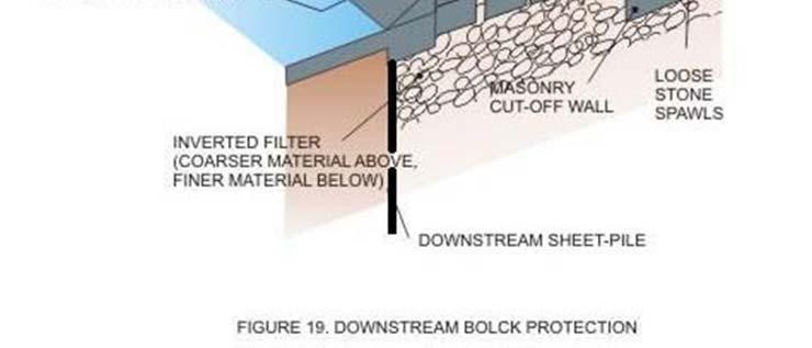
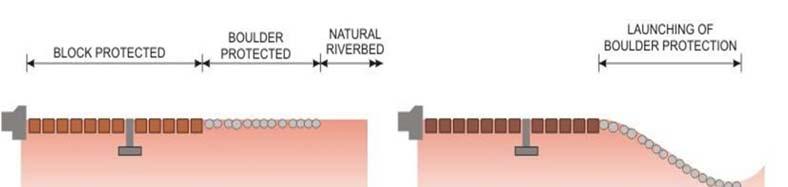
13 2 nd Semester Barrages, Regulators, Dams 13 of Computation of seepage pressure and Exit gradient. 3- Hydraulics of barrage surface flow. 4- Fixing dimensions of barrage components. 5- Protection works ; Just upstream and downstream of the solid floor of the barrage, the river bed is protected by certain methods like block protection, loose stone apron, etc. as may be seen from Figures below, showing a typical section of spillway of a barrage.

14 2 nd Semester Barrages, Regulators, Dams 14 of 15

15 2 nd Semester Barrages, Regulators, Dams 15 of 15 Structural design. After fixing all dimensions of barrages and related components, the structure design must be completed by structural engineers in order to ensures that the barrage must be able to resists all the external and internal forces such as : Buoyancy, Wind forces, Forces due to water current, Differential hydrostatic pressure with the gate of one bay open and the adjacent bay closed, Seismic forces, if any, and Hydro dynamic forces due to seismic conditions. The typical plan of barrage and related components can be illustrated with the help of figure below.
Module 4. Hydraulic structures for flow diversion and storage. Version 2 CE IIT, Kharagpur
 Module 4 Hydraulic structures for flow diversion and storage Lesson 1 Structures for Flow Diversion Investigation Planning and Layout Instructional objectives On completion of this lesson, the student
Irrigation Structures 1
 CHAPTER 8 Irrigation Structures 1 Dr. M. R. Kabir Professor and Head, Department of Civil Engineering University of Asia Pacific (UAP), Dhaka LECTURE 20 Diversion Head Works Definition: The works, which
Asst.Prof.Dr. Jaafar S. Maatooq. 1 st Semester HYDRAULIC STRUCTUER, KINDS & FUNCTIONS 1 of 26
 1 st Semester HYDRAULIC STRUCTUER, KINDS & FUNCTIONS 1 of 26 1 st Semester HYDRAULIC STRUCTUER, KINDS & FUNCTIONS 2 of 26 Water is often more useful to people when it is properly controlled, conveyed,
Using SWAT Module in the Design of Submerged Weir on narrow rivers having high flood discharge
 Using SWAT Module in the Design of Submerged Weir on narrow rivers having high flood discharge Presented by Er. Narendra Kumar Tiwary, B.Tech IIT Delhi, M.Tech NIT(Pat), Ph.D Scholar IIT Delhi Professor,
(b) Discuss in brief shaft spillway with neat sketches. Marks 04. OR Q (2) Explain in brief USBR stilling basin. Marks 08
 Discuss in brief shaft spillway with neat sketches. Marks 04. OR Q (2) Explain in brief USBR stilling basin. Marks 08") (b) Discuss in brief shaft spillway with neat sketches. Marks 04 OR Q (2) Explain in brief USBR stilling basin. Marks 08 Stilling Basins The basins are usually provided with special appurtenances including
(b) Discuss in brief shaft spillway with neat sketches. Marks 04 OR Q (2) Explain in brief USBR stilling basin. Marks 08 Stilling Basins The basins are usually provided with special appurtenances including
Solution for Irrigation Engineering
 Solution for Irrigation Engineering December 2015 Index Q.1) a). 2-3 b).3-5 c).5-6 d).6-8 e).9-10 Q.2) a).10-11 b). 12-14 c). 14-15 Q.3) a). 15-16 b). 17 c). 18 Q.4) a). N.A b). N.A c). N.A Q.5) a).20-22
Irrigation Structures 2. Dr. M. R. Kabir
 CHAPTER 9 Irrigation Structures 2 Dr. M. R. Kabir Professor and Head, Department of Civil Engineering University of Asia Pacific (UAP), Dhaka LECTURE 22 What is Cross Drainage Works? In an irrigation project,
RIVER STRUCTURAL WORKS AND OPERATION. Diversion Works (by Bizuneh Asfaw) Date of the project report
 Date of the project report") RIVER STRUCTURAL WORKS AND OPERATION Diversion Works (by Bizuneh Asfaw) Date of the project report 1 Table of Content 3.1 Introduction 3 3.1.1 General definition of headworks 3 3.1. Classification of diversion
RIVER STRUCTURAL WORKS AND OPERATION Diversion Works (by Bizuneh Asfaw) Date of the project report 1 Table of Content 3.1 Introduction 3 3.1.1 General definition of headworks 3 3.1. Classification of diversion
Module 3. Irrigation Engineering Principles. Version 2 CE IIT, Kharagpur
 Module 3 Irrigation Engineering Principles Lesson 8 Conveyance Structures for Canal Flows Instructional objectives On completion of this lesson, the student shall learn the following: 1. The need for structures
Temporary Watercourse Crossing: Fords
 Temporary Watercourse Crossing: Fords DRAINAGE CONTROL TECHNIQUE Low Gradient Velocity Control Short Term Steep Gradient Channel Lining Medium-Long Term Outlet Control Soil Treatment Permanent [1] [1]
Temporary Watercourse Crossing: Culverts
 Temporary Watercourse Crossing: Culverts DRAINAGE CONTROL TECHNIQUE Low Gradient Velocity Control Short Term Steep Gradient Channel Lining Medium-Long Term Outlet Control Soil Treatment Permanent Symbol
FORM B: DAMMING AND DIVERSION OF WATER
 APPLICATION FOR RESOURCE CONSENT FORM B: DAMMING AND DIVERSION OF WATER NOTES Resource use activities must meet all the conditions of any relevant Permitted Activity Rules in the Waikato Regional Plan
Earth Brickwork Concrete Plain Radial Drum Roller Flap. fixed. Weirs Barrages. mobile. rockfills. Gravity butress Arch Arch-gravuty Cupola.
 Dams type 1 Weirs Barrages fixed mobile Earth Brickwork Concrete Plain Radial Drum Roller Flap embankment Earthfills rockfills Dams Concrete gravity Arch Gravity butress Arch Arch-gravuty Cupola 2 Dams
Water Control Structures Selected Design Guidelines Alberta Environment Page 13-1
 Alberta Environment Page 13-1 13.0 DROP INLET SPILLWAYS 13.1 General The drop inlet spillway is commonly used for providing flood protection for earth dams which have smaller reservoirs and/or smaller
Welded Mesh Gabions and Mattresses River Protection Design Guide Anping County Zhuoda Hardware Mesh Co.,Ltd. Wire Mesh Industrial Zone, Anping
 Welded Mesh Gabions and Mattresses River Protection Design Guide Anping County Zhuoda Hardware Mesh Co.,Ltd. Wire Mesh Industrial Zone, Anping County, Hebei, P. R. China. Tel : 0086-318-7752001 7531068
Planning, Design and Estimation of a Check Dam B.H. Ramathilagam 1, S. Murugesan 2, M. Manikandan 3, A. Arumugaraja 4, Assistant professor 1 2, 3, 4
 ISSN XXXX XXXX 2017 IJESC Research Article Volume 7 Issue No.4 Planning, Design and Estimation of a Check Dam B.H. Ramathilagam 1, S. Murugesan 2, M. Manikandan 3, A. Arumugaraja 4, Assistant professor
Lyon Creek Cedar Way Stormwater Detention Dam Operation and Maintenance Manual
 Lyon Creek Cedar Way Stormwater Detention Dam Operation and Maintenance Manual Prepared by: Mike Shaw Stormwater Program Manager City of Mountlake Terrace January 2010 Section I General Information This
COTTON CREEK CULVERT REPLACMENT
 COTTON CREEK CULVERT REPLACMENT Integrating Mobility with Environmental Innovation Located along a scenic section of Highway 3/95 in British Columbia, Moyie Bluffs, a 6.5 km stretch of inland highway had
Fig: Alignment of a ridge or watershed canal (Head reach of a main canal in plains)
") SYSTEM OF IRRIGATION CANAL CHAPTER 6 Alluvial Soil and Non-Alluvial Soil The soil which is formed by transportation and deposition of silt through the agency of water, over a course of time, is called
SYSTEM OF IRRIGATION CANAL CHAPTER 6 Alluvial Soil and Non-Alluvial Soil The soil which is formed by transportation and deposition of silt through the agency of water, over a course of time, is called
DESIGN OF CHANNEL FLOW DIVERSION FACILITIES
 DESIGN OF CHANNEL FLOW DIVERSION FACILITIES FOR RIPARIAN HABITAT IRRIGATION BRUCE M. PHILLIPS, M.S., P.E. ABSTRACT Increased awareness and concern regarding environmental degradation has resulted in protection
Training on Roads for Water and Resilience
 Training on Roads for Water and Resilience ROADS AND FLOODS Floods have costs and benefits Costs: damage to infrastructure and houses, lost lives and crops Benefits: sedimentation provides fertile lands,
Application for resource consent Form B Damming and diversion of water
 Application for resource consent Form B Damming and diversion of water Notes Resource use activities must meet all the conditions of any relevant Permitted Activity Rules in the Waikato Regional Plan or
Irrigation Crossing Structures
 Irrigation Crossing Structures Road Open channel H.R. Open Irrigation Canal Tail escape Water way + Road way Culvert Bridge Water way + Water way Syphon Aqueduct Retaining walls Lining ١ 1- FUNCTION AND
ILLINOIS URBAN MANUAL PRACTICE STANDARD TEMPORARY STREAM CROSSING (no.) CODE 975. Source: Hey and Associates, Inc.
 CODE 975. Source: Hey and Associates, Inc.") ILLINOIS URBAN MANUAL PRACTICE STANDARD TEMPORARY STREAM CROSSING (no.) CODE 975 Source: Hey and Associates, Inc. DEFINITION A bridge or culvert crossing installed across a stream or watercourse for short-term
ILLINOIS URBAN MANUAL PRACTICE STANDARD TEMPORARY STREAM CROSSING (no.) CODE 975 Source: Hey and Associates, Inc. DEFINITION A bridge or culvert crossing installed across a stream or watercourse for short-term
CONSTRUCTION PLAN CHECKLIST
 CONSTRUCTION PLAN CHECKLIST The design engineer is responsible for ensuring that plans submitted for city review are in accordance with this checklist. It is requested that the executed checklist be submitted
Gabions. Introduction
 Gabions Introduction 1. A gabion is a wire mesh cage or basket filled with stones. Gabions are useful in construction works, for example to protect earth embankments, to line channels, to manage or divert
Dam Safety and Low Cost Spillway Designs
 Dam Safety and Low Cost Spillway Designs By F. Lempérière & J.P. Vigny (Hydrocoop France) THE CHALLENGE 5 th International Conference on Dam Engineering Lisbon 14-16 February 2007 Increasing dams safety
LOCATION AND DESIGN DIVISION
 VIRGINIA DEPARTMENT OF TRANSPORTATION LOCATION AND DESIGN DIVISION INSTRUCTIONAL AND INFORMATIONAL MEMORANDUM GENERAL SUBJECT: CULVERT DESIGN SPECIFIC SUBJECT: COUNTERSINKING AND LOW FLOW CONSIDERATIONS
Civil Engineering Department. 2 Marks Question and Answer. CE:2301:Irrigation Engineering
 Civil Engineering Department 2 Marks Question and Answer CE:2301:Irrigation Engineering 1 UNIT 1 INTRODUCTION 1) Define irrigation? Irrigation is defined as the science of artificial application of water
HISTORY OF CONSTRUCTION 40 CFR (c)(1)(i)-(xii) PLANT WANSLEY ASH POND (AP-1) GEORGIA POWER COMPANY. Carrollton, Georgia 30116
(1)(i)-(xii) PLANT WANSLEY ASH POND (AP-1) GEORGIA POWER COMPANY. Carrollton, Georgia 30116") (i) Site Name and Ownership Information: HISTORY OF CONSTRUCTION 40 CFR 257.73(c)(1)(i)-(xii) PLANT WANSLEY ASH POND (AP-1) GEORGIA POWER COMPANY Site Name: Site Location: Site Address: Owner: Owner Address:
(i) Site Name and Ownership Information: HISTORY OF CONSTRUCTION 40 CFR 257.73(c)(1)(i)-(xii) PLANT WANSLEY ASH POND (AP-1) GEORGIA POWER COMPANY Site Name: Site Location: Site Address: Owner: Owner Address:
Emergency Underwater Rehabilitation of the Poti Main Diversion Weir, Georgia
 Emergency Underwater Rehabilitation of the Poti Main Diversion Weir, Georgia LJILJANA SPASIC-GRIL, Jacobs, Reading, UK SYNOPSIS. The Dam Safety Project (DSP) in Georgia, which is a part of the Irrigation
Types of cross drainage works
 Definition: A cross drainage work is a structure carrying the discharge from a natural stream across a canal intercepting the stream. Canal comes across obstructions like rivers, natural drains and other
Inflow pipe. Drain. Drain
 Inflow pipe Screened overflow Drain Foul flush diverter Screened intake Manhole cover Maximum water level Seal Inspection cover Possible local drainage through screen Drain Bottom sloped Screened outlet
10(a) Bridge and culvert design information
 Bridge and culvert design information") 10(a) Bridge and culvert design information The following information is required to accompany resource consent applications for bridges or culverts on waterways. Please answer all questions if possible.
10(a) Bridge and culvert design information The following information is required to accompany resource consent applications for bridges or culverts on waterways. Please answer all questions if possible.
WEST POINT PERTINENT DATA. GENERAL Location (damsite) Troup County GA, Chambers County AL, miles above mouth of Chattahoochee River
 Troup County GA, Chambers County AL, miles above mouth of Chattahoochee River") WEST POINT PERTINENT DATA GENERAL Location (damsite) Troup County GA, Chambers County AL, miles above mouth of Chattahoochee River 201.4 Drainage area, Buford Dam to West Point Dam, square miles 2,406
WEST POINT PERTINENT DATA GENERAL Location (damsite) Troup County GA, Chambers County AL, miles above mouth of Chattahoochee River 201.4 Drainage area, Buford Dam to West Point Dam, square miles 2,406
Irrigation System. BWCDD Zanjero Training 2/13/2008
 Irrigation System BWCDD Zanjero Training Session #7 2/13/2008 Irrigation System The (main) intake structure t directs water from the source of supply, such as a reservoir or a river, into the irrigation
PRELIMINARY DESIGN OF THE HYDRAULIC STRUCTURES DAM IN THE PISÃO RIVER
 PRELIMINARY DESIGN OF THE HYDRAULIC STRUCTURES DAM IN THE PISÃO RIVER Margarida Isabel Godinho Sobral Department of Civil Engineering and Architecture, Instituto Superior Técnico - Lisbon, Portugal SUMMARY
Dams are generally constructed in the mountainous reach of the river where the valley is narrow and the foundation is good.
 [ DAMS ] 1 of 26 1-Definition : A dam is a hydraulic structure of fairly impervious material built across a river to create a reservoir on its upstream side for impounding water for various purposes. A
Flood Hazard Assessment Report Falls Gulch, Larimer County, Colorado January 16, 2013
 United States Department of Agriculture Natural Resources Conservation Service Denver Federal Center Building 56, Room 2604 P.O. Box 25426 Denver, CO 80225 720-544-2818-OFFICE alton.albin@co.usda.gov Flood
DAMS AND OTHER HYDRAULIC STRUCTURES
 GAP.2.9.1 A Publication of Global Asset Protection Services LLC DAMS AND OTHER HYDRAULIC STRUCTURES INTRODUCTION The purpose of a dam evaluation is to review the design, construction and performance history
Water distribution within the canal network
 Structures for water control and distribution 15 Chapter 4 Water flowing in a secondary irrigation canal can be divided over the tertiary canal network in several ways. One way is to divide the flow proportionally
Tulsi Prasad Phuyal Research Engineer Hydro Lab, Pulchowk, Lalitpur, Nepal
 Himalayan Small Hydropower Summit (October 12-13, 2006), Dehradun SMALL HYDROPOWER AND HEADWORKS MODELLING Tulsi Prasad Phuyal Research Engineer Hydro Lab, Pulchowk, Lalitpur, Nepal Manohar Shrestha Deputy
Modeling and Simulation of Irrigation Canals with Hydro Turbines
 Modeling and Simulation of Irrigation Canals with Hydro Turbines S Mohan Kumar Scientist, Department of Research, ABB Global Industries and Services Ltd Bangalore, India * mohan.s.kumar@in.abb.com (corresponding
Strategies to Mitigate Scour Critical Structures
 U.S. Department of Transportation Federal Highway Administration Strategies to Mitigate Scour Critical Structures Dan Ghere Hydraulics Engineer (708) 283-3557 dan.ghere@dot.gov Support Material HEC 23,
INCREASING LATERAL CAPACITY OF OLD BARRAGES INTRODUCING CABLES
 INCREASING LATERAL CAPACITY OF OLD BARRAGES INTRODUCING CABLES Ahmed Hashad 1, Yasser El-Hakem 1 and Eehab Khalil 2 1 Assistant Professor, Construction Research Institute, National Water Research Center,
1.6 Experience and challenges of spate irrigation projects in Tigray. (By Demisew Abate)
") 1.6 Experience and challenges of spate irrigation projects in Tigray (By Demisew Abate) Part I : Introduction What is spate irrigation? o Spate irrigation is a flood harvesting and management system, involving
1.6 Experience and challenges of spate irrigation projects in Tigray (By Demisew Abate) Part I : Introduction What is spate irrigation? o Spate irrigation is a flood harvesting and management system, involving
Water Resources. Associate Prof. Ahmed Moustafa Moussa Lecture -1 Lecture 4
 Water Resources By Associate Prof. Ahmed Moustafa Moussa Lecture -1 Lecture 4 High Aswan Dam Project 1. Location The High Aswan Dam (HAD) location was determined to fit the topographical features of the
SMALL HYDRO BIG CHALLENGES Renewable Energy World Asia 2016 Martin P. Bieri. September 21, 2016
 SMALL HYDRO BIG CHALLENGES Renewable Energy World Asia 2016 Martin P. Bieri September 21, 2016 CONTENT Introduction Potential in Southeast Asia Challenges in Small Hydro Main Design Steps (Bad) Examples
Supplemental Watershed Plan Agreement No. 10 for Neshaminy Creek Watershed Core Creek Dam (PA-620) Bucks County, Pennsylvania
 Bucks County, Pennsylvania") Supplemental Watershed Plan Agreement No. 10 for Neshaminy Creek Watershed Core Creek Dam (PA-620) Bucks County, Pennsylvania Project Authorization USDA's Small Watershed Program is carried out under the
Supplemental Watershed Plan Agreement No. 10 for Neshaminy Creek Watershed Core Creek Dam (PA-620) Bucks County, Pennsylvania Project Authorization USDA's Small Watershed Program is carried out under the
Performance Assessment of Taunsa Barrage Subsidiary Weir for Long Term Rehabilitation Planning
 Pak. J. Engg. & Appl. Sci. Vol. 7, Jul., 2010 (p. 65-70) Performance Assessment of Taunsa Barrage Subsidiary Weir for Long Term Rehabilitation Planning Zulfiqar Ali Chaudhry Civil Engineering Department,
Modular Sediment Barriers (Instream)
") Modular Sediment Barriers (Instream) INSTREAM PRACTICES Flow Control No Channel Flow Dry Channels Erosion Control Low Channel Flows Shallow Water Sediment Control High Channel Flows Deep Water Symbol Photo
Modular Sediment Barriers (Instream) INSTREAM PRACTICES Flow Control No Channel Flow Dry Channels Erosion Control Low Channel Flows Shallow Water Sediment Control High Channel Flows Deep Water Symbol Photo
BLOCKING AND FILLING SURFACE DRAINAGE DITCHES
 MINNESOTA WETLAND RESTORATION GUIDE BLOCKING AND FILLING SURFACE DRAINAGE DITCHES TECHNICAL GUIDANCE DOCUMENT Document No.: WRG 4A-1 Publication Date: 10/14/2015 Table of Contents Introduction Application
LOW WATER CROSSINGS, fords, or drifts, as they
 Chapter 9 For ords and Low-Water Crossings Keep the ford profile low, armor the driving surface, and protect against scour. LOW WATER CROSSINGS, fords, or drifts, as they are commonly called, can offer
Hydraulics of Jinnah Barrage; Existing Structure and Rehabilitation Alternatives
 Pak. J. Engg. & Appl. Sci. Vol. 4, Jan 2009 (p. 66-73) Hydraulics of Jinnah Barrage; Existing Structure and Rehabilitation Alternatives Z. A. Chaudhry 1 1 Professor, Civil Engineering Department, University
Water Control Structures Selected Design Guidelines Alberta Environment Page 14-1
 Alberta Environment Page 14-1 14.0 LOW LEVEL OUTLET WORKS 14.1 General In general, a low level outlet structure can be used to provide one or more of the following functions: Supply adequate water to meet
UPSC ESE/IES Civil Engineering Syllabus
 1 UPSC ESE/IES Civil Engineering Syllabus PAPER I 1. Building Materials: Stone, Lime, Glass, Plastics, Steel, FRP, Ceramics, Aluminum, Fly Ash, Basic Admixtures, Timber, Bricks and Aggregates: Classification,
Chapter 11 Culverts and Bridges
 Chapter 11 Culverts and Bridges Contents 1.0 Introduction... 1 2.0 General Design... 1 2.1 Design Criteria... 1 2.2 Design Flows... 1 2.3 Permitting and Regulations... 1 2.4 Aesthetics and Safety... 2
A Study on Physical Model Test for Cheongpyeong Dam Discharge Recalculation
 Engineering, 014, 6, 731-74 Published Online October 014 in SciRes. http://www.scirp.org/journal/eng http://dx.doi.org/10.436/eng.014.611071 A Study on Physical Model Test for Cheongpyeong Dam Discharge
Appendix E: Bridge Site Information Summary
 BRIDGE MANUAL E - 1 APPENDIX E: BRIDGE SITE INFORMATION SUMMARY Appendix E: Bridge Site Information Summary Table of Contents Notes..E 3 Section 1: Basic Information..E 4 Section 2: River Data..E 8 Section
CHAPTER 3 Environmental Guidelines for WATERCOURSE CROSSINGS GOVERNMENT OF NEWFOUNDLAND AND LABRADOR DEPARTMENT OF ENVIRONMENT AND LABOUR
 GOVERNMENT OF NEWFOUNDLAND AND LABRADOR DEPARTMENT OF ENVIRONMENT AND LABOUR CHAPTER 3 Environmental Guidelines for WATERCOURSE CROSSINGS WATER RESOURCES MANAGEMENT DIVISION Water Investigations Section
FRST 557 Lecture 7b Cross Drainage Structures: Culverts and Bridges
 FRST 557 Lecture 7b Cross Drainage Structures: Culverts and Bridges Lesson Background and Overview: The last lesson introduced the topic of water management relative to forest roads and further explored
Travers Reservoir Rehabilitation Project Irrigation Technical Conference Lethbridge, AB June 2, 2010
 Travers Reservoir Rehabilitation Project 2010 Irrigation Technical Conference Lethbridge, AB June 2, 2010 Location Plan Western Irrigation District Headworks CALGARY Eastern Irrigation District Headworks
Bridge Planning Updates. Bridge Planning Practitioners Workshop April 2012
 Bridge Planning Updates Bridge Planning Practitioners Workshop April 2012 Bridge Website Bridge Website Bridge Website Bridge Website BPG 11 Stormwater Management at Rural Bridges Released July 2010 Documents
RÍO AMOYÁ - LA ESPERANZA Hydroelectric Power Plant
 RÍO AMOYÁ - LA ESPERANZA Hydroelectric Power Plant The power plant is located in southern Tolima, in the municipality of Chaparral, approximately 150 km from Ibague. It has an installed capacity of 80
1 Small Hydro Power Plants Wetzmann
 5 th Bulgarian-Austrian Seminar SMALL DAMS AND HPP 30 March 2012, Sofia R.9 REFURBISHMENT OF TWO SMALL HYDRO POWER PLANTS IN AUSTRIA P. Tschernutter Abstract: A weir at the River Gail, which was used for
A dam and a reservoir are complements of each other.
 A dam is a hydraulic structure of fairly impervious material built across a river to create a reservoir on its upstream side for impounding water for various purposes. A dam and a reservoir are complements
WELCOME TO POND 101 OREGON WATER RESOURCES DAM SAFETY SECTION. John Falk, PE
 WELCOME TO POND 101 OREGON WATER RESOURCES DAM SAFETY SECTION John Falk, PE MISCONCEPTION 101 This is my own property..so I guess it s really none of your %*&^`!# business if I want to build a pond. R
Appendix 3-G SWM AND BMP CONSTRUCTION INSPECTIONS
 Appendix 3-G SWM AND BMP CONSTRUCTION INSPECTIONS Table of Contents APPENDIX SECTION HEADINGS 3-G.1.0 INTRODUCTION 3-G-2 3-G.1.1 Construction Inspections 3-G-2 3-G.1.2. As-Built Survey and Plan 3-G-2 3-G.1.2.1
Freight Street Development Strategy
 Freight Street Development Strategy Appendix B: Naugatuck River Floodplain Analysis Freight Street Development Strategy DECEMBER 2017 Page B-1 1.0 NAUGATUCK RIVER FLOODPLAIN AT FREIGHT STREET 1.1 Watershed
NUMERICAL ANALYSIS AND INVESTIGATION OF PIPING IN AN EARTH DAM FOUNDATION BY SOFTWARE SEEP / W (CASE STUDY OF KERMANSHAH EZGELEH EARTH DAM)
") NUMERICAL ANALYSIS AND INVESTIGATION OF PIPING IN AN EARTH DAM FOUNDATION BY SOFTWARE SEEP / W (CASE STUDY OF KERMANSHAH EZGELEH EARTH DAM) *Seyyed Hossein Naghmehkhan Dahandeh Civil Engineering, Hydraulic
NUMERICAL ANALYSIS AND INVESTIGATION OF PIPING IN AN EARTH DAM FOUNDATION BY SOFTWARE SEEP / W (CASE STUDY OF KERMANSHAH EZGELEH EARTH DAM) *Seyyed Hossein Naghmehkhan Dahandeh Civil Engineering, Hydraulic
NS-5 CLEAR WATER DIVERSION. Objectives
 CLEAR WATER DIVERSION NS-5 Objectives Erosion Control - EC Sediment Control - SE Tracking Control - TC Wind Erosion Control - WE Non-Storm Water Management - NS Waste and Materials Management - WM DESCRIPTION
Block & Aggregate Drop Inlet Protection
 Block & Aggregate Drop Inlet Protection SEDIMENT CONTROL TECHNIQUE Type 1 System Sheet Flow Sandy Soils Type 2 System [1] Concentrated Flow Clayey Soils Type 3 System Supplementary Trap Dispersive Soils
Xayaburi Hydroelectric Power Project
 The MRC Regional Workshop on Discharge and Sediment Monitoring and Geomorphological Tool for the Lower- Mekong Basin, 21-22 22 October 2008 Xayaburi Hydroelectric Power Project TEAM Consulting Engineering
Appendix J Hydrology and Hydraulics
 Appendix J Hydrology and Hydraulics Marsh Lake Dam Ecosystems Restoration Feasibility Study Hydraulics & Hydrology Appendix January 2011 Contents List of Figures iii List of Tables iii I. General 1 II.
SECTION 303 CULVERTS
 303.01 Scope - This section covers the construction of pipe culverts. 303.01.01 Definitions for the purposes of this section, the following general terms are defined as follows: a) Backfilling means the
NOT-MODELLING FOR STORMWATER AROUND THE KAIKOURA ALLUVIAL FANS
 NOT-MODELLING FOR STORMWATER AROUND THE KAIKOURA ALLUVIAL FANS Mark Pennington Pattle Delamore Partners Limited, Kaikoura, New Zealand ABSTRACT The Kaikoura plains are formed by a process of coalescing
Physical models application of flow analysis in regulated reservoir dams
 River Basin Management III 15 Physical models application of flow analysis in regulated reservoir dams M. R. M. Tabatabai 1, S. Faghihirad 2 & M. Kolahdoozan 3 1 Water Engineering Department, Power and
PAPERWORK REDUCTION ACT A. GENERAL
 U.S. DEPARTMENT OF HOMELAND SECURITY - FEDERAL EMERGENCY MANAGEMENT AGENCY RIVERINE STRUCTURES FORM O.M.B No. 1660-0016 Expires: 12/31/2010 PAPERWORK REDUCTION ACT Public reporting burden for this form
Suggested Stormwater Management Practices For Individual House Lots
 Suggested Stormwater Management Practices For Individual House Lots These practices are necessary to satisfy the water quantity and water quality criteria of the Rappahannock Stormwater Ordinance. These
APPENDIX G DIVERSION AND PELICAN LAKE CUTOFF CHANNELS HYRAULICS AND BRIDGE TECHNICAL MEMORANDUM
 APPENDIX G DIVERSION AND PELICAN LAKE CUTOFF CHANNELS HYRAULICS AND BRIDGE TECHNICAL MEMORANDUM To: File Memo From: Matt Redington, P.E. Project: Watertown South Connector CC: Date: March 6, 2007; revised
HYDRAULICS DIVISION. Assoc. Prof. Dr. Mustafa ERGİL. Assoc. Prof. Dr. Umut TÜRKER
 HYDRAULICS DIVISION Assoc. Prof. Dr. Mustafa ERGİL Assoc. Prof. Dr. Umut TÜRKER HYDRAULICS AND C.E. Civil Engineers plan, design and construct: new harbors and waterways, pipelines, irrigation and drainage
CHAPTER 8 SEEPAGE CONTROL IN EMBANKMENTS
 CHAPTER 8 SEEPAGE CONTROL IN EMBANKMENTS 8-1. General. All earth and rock-fill dams are subject to seepage through the embankment, foundation, and abutments. Seepage control is necessary to prevent excessive
Filter Tube Barriers (Instream)
") Filter Tube Barriers (Instream) INSTREAM PRACTICES Flow Control No Channel Flow Dry Channels Erosion Control Low Channel Flows Shallow Water Sediment Control High Channel Flows Deep Water Symbol Photo
Filter Tube Barriers (Instream) INSTREAM PRACTICES Flow Control No Channel Flow Dry Channels Erosion Control Low Channel Flows Shallow Water Sediment Control High Channel Flows Deep Water Symbol Photo
Module 4 Hydraulic Structures for Flow Diversion and Storage
 Module 4 Hydraulic Structures for Flow Diversion and Storage Lesson 9 Reservoir Outlet Works Instructional objectives On completion of this lesson, the student shall learn: 1. Functions of outlet works
Water Control Structures Selected Design Guidelines Alberta Environment Page 17-1
 Alberta Transportation Water Control Structures Selected Design Guidelines Alberta Environment Page 17-1 17.0 MAIN CANAL CONVEYANCE STRUCTURES 17.1 General Conveyance structures typically employed on main
ONE DIMENSIONAL DAM BREAK FLOOD ANALYSIS FOR KAMENG HYDRO ELECTRIC PROJECT, INDIA
 ONE DIMENSIONAL DAM BREAK FLOOD ANALYSIS FOR KAMENG HYDRO ELECTRIC PROJECT, INDIA S. Masood Husain Nitya Nand Rai Director Assistant Director Foundation Engineering & Special Analysis Directorate Central
Reclamation Manual Design Data Collection Guidelines Chapter 5 Typical Design Data Package Template
 Reclamation Manual The Introduction (Chapter 1) for these design data collection guidelines contains additional information concerning: preparing a design data collection request, design data collection
TOSHKA SPILLWAY BARRAGES STABILITY ANALYSIS
 Ninth International Water Technology Conference, IWTC9 5, Sharm El-Sheikh, Egypt 57 TOSHKA SPILLWAY BARRAGES STABILITY ANALYSIS Sherine S. Ismail * and Medhat Aziz ** * Researcher, Nile Research Institute,
STUDY 7.0 FISH PASSAGE
 STUDY 7.0 FISH PASSAGE STUDY 7.0 FISH PASSAGE... 7-1 1. GOALS AND OBJECTIVES OF STUDY... 7-1 2. RELEVANT RESOURCE MANAGEMENT GOALS... 7-2 3. BACKGROUND AND EXISTING INFORMATION... 7-2 4. PROJECT NEXUS...
MCKAYS CREEK HYDRO-ELECTRIC POWER SCHEME ENHANCEMENT FEASIBILITY AND SCOPING REPORT PREPARED FOR SCHEME RECONSENTING
 i MCKAYS CREEK HYDRO-ELECTRIC POWER SCHEME ENHANCEMENT FEASIBILITY AND SCOPING REPORT PREPARED FOR SCHEME RECONSENTING ii Table of contents 1 Enhancement Scope of Work 1 1.1 Introduction 1 2 McKays Intake
Stream Restoration at Road Crossings in Northern Wisconsin. Dale Higgins, USDA Forest Service
 Stream Restoration at Road Crossings in Northern Wisconsin Dale Higgins, USDA Forest Service Key Points Large # of road and trail stream crossings on the landscape Many crossings adversely impact streams
378 - POND NATURAL RESOURCES CONSERVATION SERVICE CONSERVATION PRACTICE SPECIFICATION I. SCOPE
 378-1 NATURAL RESOURCES CONSERVATION SERVICE CONSERVATION PRACTICE SPECIFICATION 378 - POND I. SCOPE The work shall consist of constructing an earthfill embankment and appurtenances to the lines, grades,
THE CONSTRUCTION PHASES OF THE NEW NAGA HAMMADI BARRAGE COFFERDAMS
 Ninth International Water Technology Conference, IWTC9 2005, Sharm El-Sheikh, Egypt 355 THE CONSTRUCTION PHASES OF THE NEW NAGA HAMMADI BARRAGE COFFERDAMS Yasser Shawky ( 1), Hala Badawy ( 2) (1) Researcher,
STORM DRAINAGE DESIGN MANUAL
 Appendix I STORM DRAINAGE DESIGN MANUAL by: SUNGATE DESIGN GROUP, P.A. GEN ERAL DESIGN STAN DARDS AN D POLICIES 1. STREET AND LOCAL DRAINAGE Discharge estimates for specified design storms shall be calculated
Control and Mitigation of Drinking Water Intake Problems along Nile River
 International Network on Sustainable Water Management i n D e v e l o p i n g C o u n t r i e s ex)(ceed SWINDON Control and Mitigation of Drinking Water Intake Problems along Nile River Gamal A. Sallam,
Stream Reaches and Hydrologic Units
 Chapter United States 6 Department of Agriculture Natural Resources Conservation Service Chapter 6 Stream Reaches and Hydrologic Units Rain clouds Cloud formation Precipitation Surface runoff Evaporation
Highway Drainage 1- Storm Frequency and Runoff 1.1- Runoff Determination
 Highway Drainage Proper drainage is a very important consideration in design of a highway. Inadequate drainage facilities can lead to premature deterioration of the highway and the development of adverse
The Study of Reservoir Immersion of a Hydropower Station
 2017 2 nd International Conference on Architectural Engineering and New Materials (ICAENM 2017) ISBN: 978-1-60595-436-3 The Study of Reservoir Immersion of a Hydropower Station Shi You Zhang, Ai Guo Li
Pier (TYP) Tainter Gate (TYP) Chapter 2 Applications General
 Tainter Gate (TYP) Chapter 2 Applications General") Chapter 2 Applications 2-1. General a. Application. Controlled spillways include crest gates that serve as a movable damming surface allowing the spillway crest to be located below the normal operating
Chapter 2 Applications 2-1. General a. Application. Controlled spillways include crest gates that serve as a movable damming surface allowing the spillway crest to be located below the normal operating
DRAFTS IN WIDE CIRCULATION
 DRAFTS IN WIDE CIRCULATION TECHNICAL COMMITTEE: CANALS AND CROSS DRAINAGE WORKS SECTIONAL COMMITTEE, WRD 13 ADDRESSED TO: Dear Sir(s), REFERENCE DATE WRD 13/T-20 14-07-2005 a) ALL MEMBERS OF WATER RESOURCES