80M 4-Square. An antenna project to obtain a bigger signal on the 80 Meter (3.5 to 3.8 MHz) amateur radio band. Bruce Whitney W8RA
|
|
|
- Bertha Stafford
- 6 years ago
- Views:
Transcription
1 An antenna project to obtain a bigger signal on the 80 Meter (3.5 to 3.8 MHz) amateur radio band Bruce Whitney W8RA
2 The Goal: Convert a vacant back field into 4.2 db of power (directional) gain Switchable to 4 compass directions Low take off angle for DX (long distances) Good performance on CW (3.51 MHz) and in the SSB DX window (3.79 to 3.80 MHz)


3 RADIATION PATTERNS The goal of 4.2 db gain is obtained by squeezing the transmit energy from 360 degrees into these smaller patterns Alternate feeding methods: Left: Quadrature Feed (hybrid), 0 o -back, 90 o - corners, 180 o -front, equal amplitude currents Right: Discrete component phasing method, 1.0 amp at 0 o -back,.9 amp at -111 o - corners,.872 amp at-218 o - front Top graphs Azimuth pattern, Bottom graphs- Vertical pattern
4 The Plan: Prep the Land 240 ft X 240 ft (1.3 Acres) Clear and Grade Flat Obtain the Materials 260 feet of aluminum tubing or pipe 170 feet of treated 6x6 timber for supports Misc. stainless rod, nuts and galv. hardware 10,000 ft of copper radial wires counterpoise 850 ft #6 stranded copper bus to connect radials together ft of high strength Dacron guy rope Phasing network and 500 ft of coaxial feed lines
5 The Plan (continued): Build the Antenna Construct the base supports Auger 13 holes- 4 for verticals and 9 for guy anchors Plant the 6x6 supports- pressure treated timbers in concrete Bury conduit for all feed lines (300 feed, 200 phasing) Lay out and staple all the radials to the ground Hydro-seed the field Erect one vertical Falling Derrick Method Erect and Test Find resonance for the first vertical and adjust length Construct the other 3 verticals - identical Erect all verticals and install phasing / feed lines Test the array for SWR bandwidth and pattern


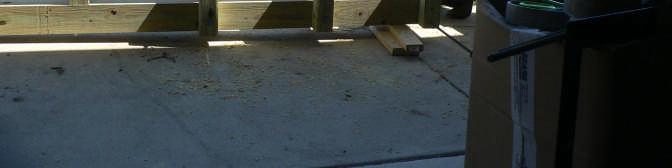
6 The min required Green Field 200 ft X 200 ft About 1 Acre


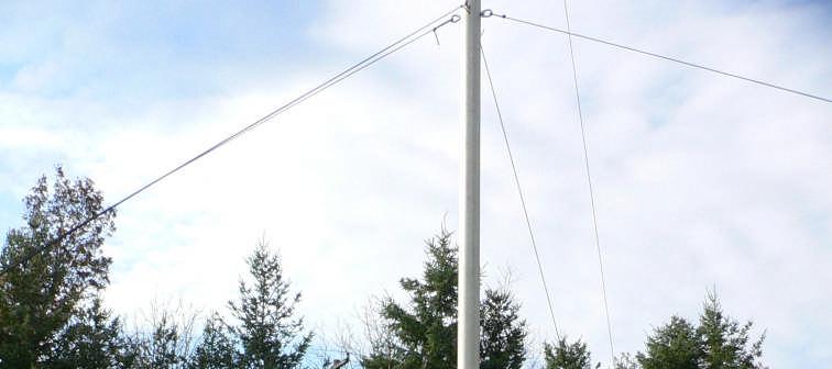
7 The Prepped Field and aluminum pipes for the antenna (verticals) Pipes are 5 schedule 40 AL, ¼ wall, 5 ½ OD, 5 lbs per ft
 The four vertical antennas are arranged in a square 65 feet on a side (1/4 wavelength). The 4-square array is directional across its diagonals.")
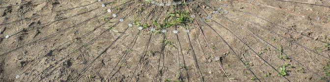
8 Antenna Layout (plan view) 4-65 foot tall vertical elements, 5 ½ inch diameter Spaced 65 feet apart in a square 48 radial wires 65 feet long for each vertical - 2 miles (10,000+ ft) of radial wires laid on the ground in pattern (below) The four vertical antennas are arranged in a square 65 feet on a side (1/4 wavelength). The 4-square array is directional across its diagonals. The 4-square system phasing unit is located in the center of the square with 75 ohm coaxial cables feeding each vertical.
9 Vertical Element Support 5 ½ AL pipe Side view 6 ½ nylon bushings 4x4 treated timbers 6x6 treated timbers 66 Hinge Pin 5/8 threaded rod inside ¾ PVC conduit nylon washers ground line 54 concrete The 5 ½ inch OD aluminum pipe is supported between two 6 x6 by 10 ft pressure treated SPF timbers, in concrete - 54 deep in the earth. The pipe is insulated from the wood by two machined nylon bushings 6 ½ square. The top bushing is held by 4 x4 horizontal braces on both sides, double bolted through the 6 x6 s with ½ threaded rod and nuts. The bottom bushing is pinned through the 6 x6 s and pipe with 5/8 threaded rod inside a piece of ¾ PVC electrical conduit with nylon washers on the ends thus providing double insulation from the wood. A single 3/8 diameter hole is drilled through the pipe at the bottom for attaching the feed wire


10 Vertical Element Support 5 ½ AL pipe 6 ½ nylon bushings 4x4 treated timbers 6x6 treated timbers hinge pin 5/8 threaded rod inside ¾ PVC conduit nylon washers feed coax & wire radial plate concrete The 5 ½ inch OD aluminum pipe is supported between two 6 x6 by 10 ft pressure treated SPF timbers, in concrete - 54 deep in the earth. The pipe is insulated from the wood by two machined nylon bushings 6 ½ square. The top bushing is held by 4 x4 horizontal braces on both sides, double bolted through the 6 x6 s with ½ threaded rod and nuts. The bottom bushing is pinned through the 6 x6 s and pipe with 5/8 threaded rod inside a piece of ¾ PVC electrical conduit with nylon washers on the ends thus providing double insulation from the wood. A single 3/8 diameter hole is drilled through the pipe at the bottom for attaching the feed wire
11 Guying System 5/16 diam lb breaking strength Dacron ropes at 3 levels in 4 directions (828 ft) on each of the 4 verticals (3312 ft total) All guy points secured with 5/8 utility grade galvanized eye bolts and eye nuts Erection Method Falling Derrick (25 ) pulled by 1/2 nylon rope and pulleys to raise 65 foot vertical
")
12 All verticals guyed to 9 guy timbers 48 guy lines, 3312 ft of Dacron guy rope Wind survival greater than 90 MPH (estimated) with ice


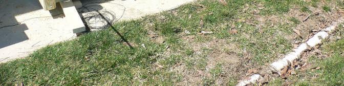


13 The Supports and Conduits


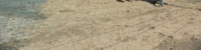


14 Work in Progress


15 Work in Progress


16 Work in Progress


17 Center guy support, feed lines and DXE phasing network Erecting anchor eyebolt in concrete

18 Impedance Plot Single Vertical
19 SWR & DUMP LOAD PERFORMANCE 10% SWR 1.6 9% 8% 7% 6% 1.5 5% 1.4 4% 1.3 3% 1.2 2% 1.1 1% % Frequency MHZ DIR SWR OMNI SWR DUMP PWR Note: zero power dumped in Omni DUMP PWR NOTE: 4 square spacing, phasing line length and single vertical resonance all set for KHz
20 TO BE CONTINUED 1. Measure Front to Back ratio at frequencies throughout the band to determine performance bandwidth 2. Cut different length phasing lines for CW, center band and SSB DX window check SWR and F/B performance bandwidth
Houston Community College 3200 Main Parking Garage November 15, 2010 Houston Community College
 SECTION 323113 - CHAIN LINK FENCES AND GATES PART 1 - GENERAL 1.1 RELATED DOCUMENTS A. Drawings and general provisions of the Contract, including General and Supplementary Conditions and Division 01 Specification
Foundation Manual. Part Number: Version: Updated: July 5, S. Meadows Pkwy. A-9, #329 Reno, NV
 Foundation Manual Part Number: 150002 Version: 1.22 Updated: July 5, 2009 748 S. Meadows Pkwy. A-9, #329 Reno, NV 89521 775-831-9463 www.mariahpower.com July 2009, Mariah Power, All Rights Reserved Dear
Underground Residential Distribution (Specifications for Installation) PES March 2008 Spec 11
 PES March 2008 Spec 11") Underground Residential Distribution (Specifications for Installation) PES March 2008 Spec 11 Underground Residential Distribution (URD) Index General Discussion... 1-2 Description... 3-7 Drawings (Available
Underground Residential Distribution (Specifications for Installation) PES March 2008 Spec 11 Underground Residential Distribution (URD) Index General Discussion... 1-2 Description... 3-7 Drawings (Available
PV Mounting System 2703 SERIES 200 UL GROUND MOUNT SYSTEM. SnapNrack Residential PV Mounting Systems Code Compliant Installation Manual
 PV Mounting System 2703 SERIES 200 UL GROUND MOUNT SYSTEM SnapNrack Residential PV Mounting Systems Code Compliant Installation Manual Series 200 UL Introduction Series 200 UL Introduction SnapNrack Series
HF Tower Collapse ! We re not the only ones. NSARC HF Operators 1 KFI KRBC-TV
 HF Tower Collapse! We re not the only ones. KFI KRBC-TV NSARC HF Operators 1 Building the Original! 24 foot Aluminum tower! TH6 3 element tri-band (20/15/10M) yagi! Restrictions " No guy points no guy
POST FRAME BUILDING STANDARDS
 CASS COUNTY, MISSOURI BUILDING CODES, ENVIRONMENTAL HEALTH AND ZONING DEPARTMENT 30508 S. West Outer Road, Harrisonville, MO 64701 P- (816) 380-8134 F- (816) 380-8130 POST FRAME BUILDING STANDARDS 201.3
A. Product Data shall be provided for each type of product indicated.
 32 31 13 CHAIN LINK FENCES AND GATES SECTION 1 GENERAL 1.1 SUMMARY This Section includes the following: 1. Chain Link Fences 2. Gates for Chain Link Fences. See electrical specifications for electrical
CONDUITS AND FITTINGS
 CONDUIT AND FITTINGS Rigid Steel Conduit 3801 Rigid PVC Conduit 3803 HDPE Conduit 3803 Flexible Non Metallic Liquid Tight Conduit Type LFNC-B 3804 PVC Coated Urethane Lined Galvanized Rigid Steel Conduit
Practical Checklists of Best Practices Frank Donovan, W3LPL
 Design, Construction and Maintenance of Antennas and Towers for Storm Survival and Long Term Reliability Practical Checklists of Best Practices Frank Donovan, W3LPL Typical A Typical Guyed Guyed Tower
DESIGN GUIDELINES WIRING AND CONDUITS PAGE 1 of 7
 DESIGN GUIDELINES WIRING AND CONDUITS PAGE 1 of 7 1.1. REFERENCE STANDARDS 1.1.1. Publications listed below (including amendments, addenda, revisions, supplements and errata) form a part of this specification
Electric Service Handbook
 Electric Service Handbook Revised August 2017 Contact Information Telephone (253): Electrical Inspection Office 502-8277 7:30 am - 4:30 pm Electrical Inspectors Area Map on Website 7:30 am - 8:30 am Automated
UNDERGROUND SERVICES SECONDARY
 Reference UNDERGROUND SERVICES SECONDARY Underground services secondary... U- 1 General requirements for underground service... U- 2 Name of parts for underground service... U- 3 Conduit layouts... U-
SPECIAL SPECIFICATION 8826 Self Supporting Communications Tower (20 to 100 feet)
") 2004 Specifications CSJ 2103-01-030 SPECIAL SPECIFICATION 8826 Self Supporting Communications Tower (20 to 100 feet) 1. Description. Furnish and install 100 foot tall or less, self-supporting light duty
2004 Specifications CSJ 2103-01-030 SPECIAL SPECIFICATION 8826 Self Supporting Communications Tower (20 to 100 feet) 1. Description. Furnish and install 100 foot tall or less, self-supporting light duty
SECTION GROUNDING AND BONDING
 SECTION 16060 PART 1 GENERAL 1.01 DESCRIPTION A. Section includes requirements for an electrical grounding system, including electrodes, grounding rods, connectors, insulators, equipment grounding and
CHAIN LINK FENCES AND GATES
 SECTION 02831 CHAIN LINK FENCES AND GATES PART 1 GENERAL 1.01 SUMMARY A. Alternate Material for Fence Post and Framing Material: Where schedule 40 galvanized steel is specified, the following will be accepted:
D D TYPE A1, A2 & B MICHIGAN DEPARTMENT OF TRANSPORTATION 5-40 CONNECTION. L4" x 4" x 3/8" Brace. C8 x 4.25 Strut. WT9 x 17.5.
 Sign length minus Adjust to avoid interference with sign legend A Deck fascia A 6" Equal Equal 6" Sign length (L) varies 6 to 12 PLAN 0 CONNECTION (DECK FASCIA) Angle connection assembly F Face of concrete
Electric Service Standards
 V: 1 of 6 A. Padmounted Requirements Complete requirements are contained in FPL specifications given to Customers for individual projects. Typical pad mounted transformer requirements include, but are
CHAPTER 11 CONDUITS AND FITTINGS
 CONDUITS AND FITTINGS CHAPTER 11 CONDUITS AND FITTINGS The standards and requirements for conduits and fittings used for traffic control signal and lighting systems are presented in this chapter. 11.1
MERCHANTS METALS. A. ASTM F552 Standard Terminology Relating to Chain Link Fencing
 MERCHANTS METALS SECTION 32 31 13 COLORBOND CHAIN LINK FENCE AND GATES 2014 PART 1 GENERAL 1.1 RELATED DOCUMENTS A. DIVISION 01 - GENERAL REQUIREMENTS: Drawings, quality, product and performance requirements,
PATENTS ARE PENDING. Building Dimensions. Exterior Dimensions Roof Edge to Roof Edge
 Assembly Manual 8x9 PATENTS ARE PENDING Approximate Size 7640303 Storage Area Building Dimensions Exterior Dimensions Roof Edge to Roof Edge Interior Dimensions Wall to Wall Sq. Ft. Cu. Ft. Width Depth
Modular CABANA Kit 16 x 16 (6x6) Lumber: Western Red CEDAR #1 (Cabinet) Shingles: 5X / 16" long / 1/2" thick or 16 oz. copper
 Lumber: Western Red CEDAR #1 (Cabinet) Shingles: 5X / 16 long / 1/2 thick or 16 oz. copper") Lumber: Western Red CEDAR #1 (Cabinet) Shingles: 5X / 16" long / 1/2" thick or 16 oz. copper Modular CABANA Kit 16 x 16 (6x6) Hipped Roof & Build-in Transoms Entry Key Lock Set (bright brass or dark bronze)
Lumber: Western Red CEDAR #1 (Cabinet) Shingles: 5X / 16" long / 1/2" thick or 16 oz. copper Modular CABANA Kit 16 x 16 (6x6) Hipped Roof & Build-in Transoms Entry Key Lock Set (bright brass or dark bronze)
Table of Contents. Page Title
 Page Title Table of Contents 1 Floor plan/ Room utilization 2 Elevation (EAST) 3 Elevation (SOUTH) 4 Elevation (WEST) 5 Elevation (NORTH) 6 Foundation plan details 7 Foundation cross sections A Main grade
WIND SPEED AND DESIGN CRITERIA FOR FLEXIBLE FACE SIGNS CONSTRUCTED OF ABC EXTRUSIONS
 WIND SPEED AND DESIGN CRITERIA FOR FLEXIBLE FACE SIGNS CONSTRUCTED OF ABC EXTRUSIONS 2005 EDITION This edition is based upon ASCE 7-98 recommendations for wind speed and wind loads. These have changed
GUY-GRIP Dead-end NOMENCLATURE GENERAL INFORMATION SAFETY CONSIDERATIONS
 GUY-GRIP Dead-end NOMENCLATURE Please visit our web site at www.preformed.com for additional literature.guy-grip Dead-end Application Procedure - SP2045 Cross-over Marks: (A) Indicate starting point for
Fig. 1 - Standard Clevis Hanger
 Revision 10/24/2007 Fig. 1 - Standard Clevis Hanger Component of State of California OSHPD Approved Seismic Restraints System Size Range Size 1/2" thru 36" pipe. Function Recommended for the suspension
GroundTrac. Installation Manual
 APPLICATION: The GroundTrac system is designed with a minimum amount of installed footings at greatly reduced labor. The system integrates with ordinary 1-1/2 schedule #40 galvanized water pipe. This ground
UNDERGROUND SERVICES (RESIDENTIAL) SINGLE FAMILY RESIDENTIAL, DUPLEXES, OR TOWNHOUSES
 SINGLE FAMILY RESIDENTIAL, DUPLEXES, OR TOWNHOUSES") 7.01 GENERAL UNDERGROUND SERVICES (RESIDENTIAL) SINGLE FAMILY RESIDENTIAL, DUPLEXES, OR TOWNHOUSES Also refer to Chapter 3 (Service Entrances), and Chapter 4 (Metering Installation). OPPD will install,
7.01 GENERAL UNDERGROUND SERVICES (RESIDENTIAL) SINGLE FAMILY RESIDENTIAL, DUPLEXES, OR TOWNHOUSES Also refer to Chapter 3 (Service Entrances), and Chapter 4 (Metering Installation). OPPD will install,
ROOF MOUNT KIT OWNERS MANUAL
 ROOF MOUNT KIT OWNERS MANUAL Made in the USA by: Primus Wind Power, Inc. 938 Quail St. Lakewood, CO 80215 Phone: (303) 242-5820 www.primuswindpower.com AIR is a trademark of Primus Wind Power, Inc. ROOF
Tower Site Inspection Procedures
 Engineering, Manufacturing, Construction & Erection Specializing in Radio & TV Communication Towers 6037 S. Industrial Rd. 918-789-9020 Office 918-789-9922 Fax www.belltowercorp.com bob@belltowercorp.com
SECTION CHAIN-LINK FENCES AND GATES 02821/1
 SECTION 02821 - CHAIN-LINK FENCES AND GATES 02821/1 PART 1 - GENERAL 1.1 SUMMARY A. This Section includes the following: 1. Chain-Link Fences: 2. Gates: horizontal slide or swing. 3. Fences installed where
GARAGES/ONE-STORY City of Grand Rapids Building Safety Division
 GARAGES/ONE-STORY City of Grand Rapids Building Safety Division 218-326-7601 www.cityofgrandrapidsmn.com This handout is intended only as a guide and is based in part on the 2015 Minnesota State Building
HANDSET WALL FORM. Handset Wall Form. Quick Assembly - can be built using only a hammer. Reduced weight increases productivity
 HANDSET WALL FORM Quick Assembly - can be built using only a hammer Reduced weight increases productivity Unsurpassed flexibility in design and availability of panels for a wide variety of applications
Scaffolding and Raised Platforms
 Standard Operating Procedures Scaffolding and Raised Platforms Last Modified: JAN 2013 1 of 7 Scaffolding and Raised Platforms I Purpose To provide a guideline for personnel who work around or on stationary
EXCEL MODULAR STANDARD SCAFFOLD COMPONENT TECHNICAL MANUAL
 EXCEL MODULAR STANDARD SCAFFOLD COMPONENT TECHNICAL MANUAL EMSLC-TSM-1001 Engineering Approval: Lance Smith Manual Release Date: 04/25/2017 Release Authorization: ECN EMSLC-0191 Revision: AK TABLE OF
ITEM L-119 AIRPORT OBSTRUCTION LIGHTS DESCRIPTION
 SECTION 74 AIRPORT OBSTRUCTION LIGHTS (FAA L-119) 74-1 GENERAL The Contractor shall perform all work required by the plans and specifications for construction of obstruction lights in accordance with the
SECTION HANGERS AND SUPPORTS FOR ELECTRICAL SYSTEMS
 SECTION 26 05 29 HANGERS AND SUPPORTS FOR ELECTRICAL SYSTEMS PART 1 GENERAL 1.1 DESCRIPTION A. Scope: 1. CONTRACTOR shall provide all labor, materials, equipment, and incidentals as shown, specified, and
Safety on Heights: Our Policy
 11/17/14 Safety on Heights: Our Policy Only volunteers over the age of 18 are allowed to work on heights of more than six feet off the ground. This includes all work on scaffolds. Only volunteers who are
Douglas County Traffic Signal Installation Guidelines (January 2013)
") Douglas County Traffic Signal Installation Guidelines (January 2013) The following guidelines are minimum requirements for equipment installation. Section A. Poles and Foundations ( Wood, Concrete, Mast
Douglas County Traffic Signal Installation Guidelines (January 2013) The following guidelines are minimum requirements for equipment installation. Section A. Poles and Foundations ( Wood, Concrete, Mast
SECTION I -- IRONWORK
 SECTION I -- IRONWORK CONTENTS PAGE 1. GENERAL... I-2 1.1. Introduction... I-2 2. REQUIREMENTS... I-2 2.1. General... I-2 2.2. Auxiliary Framing... I-2 2.3. High Seismic Risk Zone Requirements... I-3 2.4.
B. Polyethylene samples shall be submitted for Owner approval of color and quality.
 Glass Rail ENGINEERED DASHERBOARD SPECIFICATIONS PART 1 - GENERAL 1.01 PROJECT SCOPE A. Contractor shall furnish and install one complete set of steel framed dasherboards as indicated on the drawings and
Smarter. Safer. Leaner.
 Smarter. Safer. Leaner. Fast Installation and Removal Decrease Leading Edge Exposure by 87% OSHA Compliant Versatile and Reusable Use Perimeter Protection Posts During Construction: At Building Perimeter
2008 NEC Guide Lines for Home Owner Doing Electrical Work on their Property
 2008 NEC Guide Lines for Home Owner Doing Electrical Work on their Property A brief summary of the most used code references for residential wiring State of Idaho Division of Building Safety Electrical
SECTION VIBRATION CONTROLS FOR HVAC PIPING AND EQUIPMENT
 SECTION 230548 - PART 1 - GENERAL 1.1 SUMMARY A. This Section includes the following: 1. Elastomeric Isolation pads. 2. Elastomeric Isolation mounts. 3. [Freestanding] [Restrained] [Freestanding and restrained]
John Corini - PE. Key To Successful Tower Installations: Under Stack And Over Guy
 John Corini - PE Key To Successful Tower Installations: Under Stack And Over Guy Tom Wagner N1MM 1 KE1IH BACKGROUND First Licensed as KA1MDG in 1983 One of The YCCC Smaller Guns Practicing Design/Structure
SECTION (Master Template Final-05) ELECTRICAL BOXES. A. Provide boxes for electrical equipment and wiring devices as follows:
 ELECTRICAL BOXES. A. Provide boxes for electrical equipment and wiring devices as follows:") SECTION 16130 (Master Template Final-05) ELECTRICAL BOXES PART 1 GENERAL 1.01 SECTION INCLUDES A. Provide boxes for electrical equipment and wiring devices as follows: 1. Wall and ceiling outlet boxes.
SECTION 16130 (Master Template Final-05) ELECTRICAL BOXES PART 1 GENERAL 1.01 SECTION INCLUDES A. Provide boxes for electrical equipment and wiring devices as follows: 1. Wall and ceiling outlet boxes.
SECTION Summit Phenolic Lockers (Solid Phenolic Lockers)
") SECTION 10 51 00 Summit Phenolic Lockers (Solid Phenolic Lockers) Part 1-General 1.01 Summary A. Section includes: solid phenolic lockers solid phenolic benches 1.02 Submittals A. Submittals: Comply with
SECTION 10 51 00 Summit Phenolic Lockers (Solid Phenolic Lockers) Part 1-General 1.01 Summary A. Section includes: solid phenolic lockers solid phenolic benches 1.02 Submittals A. Submittals: Comply with
CONSULTANT PROCEDURES & DESIGN GUIDELINES Electrical Manholes and Handholes UNIVERSITY OF MISSOURI
 GENERAL: The scope of this document is to provide instruction for the installation of concrete electric manholes. DESIGN GUIDELINES: 1. Materials for Manhole 1.1. Cast-in-Place or Pre-Cast concrete may
Basic Service. This Section provides information regarding a. Introduction
 Basic Service Introduction This Section provides information regarding a new electric Basic Service for a single phase service less than or equal to 400 amps, and a three phase service less than 50kW.
(Condensed from National Electric Code)
") WIRING, SPECIFICATIONS, INSPECTION, AND METER INSTALLATION PROCEDURES FOR RESIDENTIAL CUSTOMERS SERVED BY SOUTHWEST ARKANSAS ELECTRIC COOPERATIVE CORPORATION Effective April 1, 1974 Revised February 3,
WIRING, SPECIFICATIONS, INSPECTION, AND METER INSTALLATION PROCEDURES FOR RESIDENTIAL CUSTOMERS SERVED BY SOUTHWEST ARKANSAS ELECTRIC COOPERATIVE CORPORATION Effective April 1, 1974 Revised February 3,
ITT# 5P /A Page 1 of 6 Bison Paddock Fence Removal & Replacement. Statement of Work
 ITT# 5P420-11-5047/A Page 1 of 6 1. Purpose: Statement of Work To install approximately 1.88 kilometers of new bison paddock fence in Waterton Lakes National Park, including the removal and proper environmental
2015 Georgia Grazing School: Choosing the right fence, fence charger, and wire or tape for your grazing system
 Choosing the Right Fence, Charger, and Wire or Tape for Your Grazing System 2015 Georgia Grazing School Fencing Systems Plan the system before building Choose the right materials Use the right construction
Section BUILDINGS, SHELTERS, ENCLOSURES
 Section 13121 BUILDINGS, SHELTERS, ENCLOSURES Part 1 GENERAL 1.1 SECTION INCLUDES 1.2 A. Pre-engineered buildings. B. Pre-engineered shelters. C. Pre-engineered enclosures. D. Electrical wiring and devices
American Metal Specialties, Inc.
 American Metal Specialties, Inc. www.cablerailings.com (253) 272-9344 (253) 627-3843 Fax PART 1 GENERAL 1.1 SECTION INCLUDES SECTION 05 73 00 STAINLESS STEEL ORNAMENTAL HANDRAILS AND RAILINGS For best
Masonry Wall Bracing. A Simplified Approach To Bracing Masonry Walls Under Construction. Masonry Bracing Task Force.
 Masonry Wall Bracing A Simplified Approach To Bracing Masonry Walls Under Construction Produced by the Masonry Wall Bracing A Simplified Approach to Bracing Masonry Walls Under Construction Produced by
DOUBLE SLIDE RAIL INSTALLATION METHOD. Double Slide Rail August
 Double Slide Rail August 2015 1 DOUBLE SLIDE RAIL INSTALLATION METHOD Introduction Slide rail shoring systems can be used for trenches up to 12m wide and 6m deep. Module length is determined by panels
2003 International Residential Code ELECTRICAL PROVISIONS ONLY October 2005 EDITORIAL CHANGES SEVENTH PRINTING
 2003 International Residential Code ELECTRICAL PROVISIONS ONLY October 2005 EDITORIAL CHANGES SEVENTH PRINTING E3305.3: now reads The space equal to the width and depth of the panelboard and extending
Building Construction Occupations
 Job Ready Assessment Blueprint Building Construction Occupations Test Code: 2011 / Version 01 Measuring What Matters Specific Competencies and Skills Tested in this Assessment: Safety and General Knowledge
CITY OF FARGO SPECIFICATIONS SIGNING
 SIGNING PART 1 DESCRIPTION OF WORK The work to be done under this section of the Specifications and the accompanying plans consists of furnishing all labor, material and accessories necessary to complete
Tom Taormina, K5RC Amateur Radio Emergency Coordinator Storey County NV
 Tom Taormina, K5RC Amateur Radio Emergency Coordinator Storey County NV Attachment to Building Permit Application Amateur Radio Antenna Support Structures Submitted to the Storey County Building Department
A. All materials shall be tested and listed by an OSHA approved Nationally Recognized Testing Laboratory (NRTL).
.") 16450 GROUNDING ************************************************************************************************************* SPECIFIER: CSI MasterFormat 2004 number: 26 05 26 An optional keynote to the
16450 GROUNDING ************************************************************************************************************* SPECIFIER: CSI MasterFormat 2004 number: 26 05 26 An optional keynote to the
Overturning Forces. 12 times 300 lbs = 3,600 lbs of shear force along top of wall. Shear Wall
 2,400 lbs of compression Overturning Forces Overturning forces act on all shear walls. However, sometimes a shear wall will be subjected to very strong overturning forces that can damage the shear wall.
SECTION SEISMIC CONTROL OSHPD
 SECTION 01451 PART 1 - GENERAL 1.01 DESCRIPTION A. Provide all required seismic restraints and calculations in order to insure that the installation of all architectural, mechanical, and electrical equipment/components
CITY OF LOS ANGELES CALIFORNIA
 BOARD OF BUILDING AND SAFETY COMMISSIONERS VAN AMBATIELOS PRESIDENT E. FELICIA BRANNON VICE PRESIDENT JOSELYN GEAGA-ROSENTHAL GEORGE HOVAGUIMIAN JAVIER NUNEZ CITY OF LOS ANGELES CALIFORNIA ERIC GARCETTI
Lifting Sockets. Flat Lifting Sockets
 Lifting sockets are widely used in the application of precast concrete construction, such as lifting beams, wall and floor slabs etc.. A reinforcement bar is to be inserted through the cross hole to transfer
How to Construct a Feral Enclosure
 How to Construct a Feral Enclosure by Bob Breeze For questions and further information: bob.breeze@gmail.com April 2016 Please note, this is a living document. If you need further information or would
De Montfort Mark 7 Incinerator (Flatpack)
") De Montfort Mark 7 Incinerator (Flatpack) Introduction This design is specially for those occasions when a large number of incinerators are to be built at one location and transported to the places where
De Montfort Mark 7 Incinerator (Flatpack) Introduction This design is specially for those occasions when a large number of incinerators are to be built at one location and transported to the places where
1. Hangers and supports for electrical equipment and systems. 2. Construction requirements for concrete bases.
 SECTION 260529 - HANGERS AND SUPPORTS PART 1 - GENERAL 1.1 SUMMARY A. Section includes: 1. Hangers and supports for electrical equipment and systems. 2. Construction requirements for concrete bases. 1.2
2005 Seismic Bracing System. Kindorf Modular Metal Framing
 2005 Seismic Bracing System Kindorf Modular Metal Framing What is Seismic Bracing? Seismic Bracing is support systems that account for forces generated by an earthquake Vertical Pipes or Duct hanging overhead
B B B B3104 CT B3104CT CT B3104CT B3100C AS B422 Right Angle Clamp
 EMPIRE ANVIL PHD BLINE 11 11B Plain Carbon Steel (1/2 24 ) 260 450 B3100 11G ElectroGalvanized (1/2 24 ) 11SS T304 Stainless (1/2 14 ) Adjustable Clevis 11GI 11GI ElectroGalvanized (1/2 12 ) 260 450 B3100
Materials Carbon Steel is used in the manufacturing of riser and pipe clamps. Stainless Steel and other materials are available.
 Pipe clamps offered in this section are designed for support and attachment of pipe to structural members. wide range of pipe clamps are available for various applications. Materials arbon Steel is used
Section 2: Underground
 Section 2: Underground GENERAL INSTALLATION REQUIREMENTS FOR UNDERGROUND FACILITIES Underground electric service and meter location will be established by NHEC upon site visit. In some instances the type,
SECTION LIGHT DUTY SLIDING AND STACKING GLASS DOOR SYSTEMS
 Page 1 of 9 SECTION 10 2238.13 LIGHT DUTY SLIDING AND STACKING GLASS DOOR SYSTEMS USE THIS SECTION WHEN SPECIFYING OVERHEAD SUPPORTED FOLDING GLASS PANEL PARTITIONS. SECTION INCLUDES OVERHEAD TRACK ASSEMBLY,
SECTION SLUICE GATES
 SECTION 11100 SLUICE GATES PART 1--GENERAL Fill in the blank with a short description of sluice gate usage, i.e., for isolation of wastewater, or for tank drainage, or for control of water surface. 1.01
SECTION PRE-ENGINEERED MEMBRANE STRUCTURE
 SECTION 13125 PART 1 - GENERAL 1.1 SUMMARY A. Section includes the design, engineering, fabrication and erection of a frame-supported, tensilemembrane structure complete with entrance and exit doors and
B R OA DWAY RAC K. High Security
 B R OA DWAY RAC K High Security The Broadway Rack is a great fit on Broadway or in areas where maximum security is a top priority. Made of thick, two-inch square steel, the Broadway Rack renders pipe-cutters
EXTERNAL GROUNDING (EARTHING)
") EXTERNAL GROUNDING (EARTHING) CHAPTER 4 This chapter provides requirements and guidelines for designing and installing the external grounding (earthing) electrode system at a communications site. This
EXTERNAL GROUNDING (EARTHING) CHAPTER 4 This chapter provides requirements and guidelines for designing and installing the external grounding (earthing) electrode system at a communications site. This
SECTION VIBRATION AND SEISMIC CONTROLS FOR ELECTRICAL SYSTEMS
 PART 1 - GENERAL 1.1 RELATED DOCUMENTS A. Drawings and general provisions of the Contract, including General and Supplementary Conditions, apply to this Section. 1.2 SUMMARY A. This Section includes the
ENGINEERING DESIGN & IMPROVEMENT STANDARDS
 ENGINEERING DESIGN & IMPROVEMENT STANDARDS 2016 Prepared by: Engineering Division For latest edition of these Improvement Standards, refer to City of Visalia website at: www.visalia.city/engineeringdocuments
ROLLING RACK. Simple Security
 Simple Security The graceful design and high security of the Rolling Rack has made this type of bike rack a standard for many schools and communities. The Rolling Rack can be used as a single-sided or
1. Vertical reciprocating conveyor, Hydraulic straddle VRC.
 PART 1: GENERAL 1.01 Section Includes: 1. Vertical reciprocating conveyor, Hydraulic straddle VRC. a. Machine, controller, platform, structural steel hoist frame. b. Wire mesh enclosure and gates. Related
Seismic Installation Manual
 Seismic Installation Manual This manual provides the design strength capacities and installation guidelines for the Restraint systems brace components for use in the design of an overall bracing/restraint
ENGINEERED POWER SOLUTIONS
 Date: May 2, 2017 Subject: To: From: Structural Overview of Earth Anchors For PV Ground Mounted Arrays Brian Boguess Nuance Energy Group, Inc. Matthew Gilliss Engineered Power Solutions (EPS) INTRODUCTION
SECTION ALUMINUM STORM WINDOWS
 PART 1 - GENERAL 1.1 DESCRIPTION: SECTION 08 51 69.11 ALUMINUM STORM WINDOWS SPEC WRITER NOTES: 1. Delete between // // if not applicable to project. 2. Also delete any other item or paragraph not applicable
OVERSHOT GATE TECHNICAL DATA SHEET
 FRESNO OVERSHOT GATE TECHNICAL DATA SHEET Applications Fresno Overshot Gates effectively control upstream and downstream levels of canals. Improved flow control is achieved through the use of this fully
Projector mounts. CMA115 6 (152 mm) CEILING PLATES. concrete. vaulted. CMA330 8 (203 mm) CMA700 6 (152 mm)
 CEILING PLATES. concrete. vaulted. CMA330 8 (203 mm) CMA700 6 (152 mm)") CEILING PLATES CMA105 4 (102 mm) Flat Ceiling Plate General purpose ceiling plate with small mounting footprint Use with short columns or when mounting space is limited concrete CMA330 & CMA345 CMA100
CEILING PLATES CMA105 4 (102 mm) Flat Ceiling Plate General purpose ceiling plate with small mounting footprint Use with short columns or when mounting space is limited concrete CMA330 & CMA345 CMA100
HIGH MAST CAMERA POLE ASSEMBLY GENERAL
 10-3.24 HIGH MAST CAMERA POLE ASSEMBLY GENERAL The Contractor must furnish and install the following equipment for high mast camera pole assembly as described herein and as shown on the plans: 1. Camera
SECTION CHAIN LINK FENCES AND GATES
 SECTION 32 31 13 SPEC WRITER NOTES: Use this section only for NCA projects. Delete text between // // not applicable to project. Edit remaining text to suit project. PART 1 - GENERAL 1.1 SUMMARY A. Section
1 Exam Prep Placing Reinforcing Bars Tabs and Highlights
 1 Exam Prep Placing Reinforcing Bars Tabs and s These 1 Exam Prep Tabs are based on the CRSI Placing Reinforcing Bars Recommended Practices, 9 th Edition. Each 1 Exam Prep tabs sheet has five rows of tabs.
REV. 9/08. Mounting Structure PRE-INSTALLATION GUIDE for Ergon Skybooms
 REV. 9/08 Mounting Structure PRE-INSTALLATION GUIDE for Ergon Skybooms SKYTRON MOUNTING STRUCTURES for Ceiling Mounted Equipment Foreword Skytron s objective is to provide a program and guideline to assist
Seismic Restraints. Cent-R-Rail Supplement* SYSTEMS THAT MAKE SENSE
 SRSCR-0 Seismic Restraints Cent-R-Rail Supplement* Multi-Directional Bracing For Data-Track, Half-Rack and Multi-Tier Half-Rack Systems Structural Engineer S 9 *To be used in conjunction with Cooper B-Line
HELIOSTAR 252, 218 VERTICAL, FREE INSTALLATION
 HELIOSTAR 252, 218 VERTICAL, FREE INSTALLATION INSTRUCTION MANUAL ENERGY AND SANITARY SYSTEMS Installation requirements General requirements The free-standing installation set is to be used or installing
Delivering Reliability. Electrical Vaults. Power & Energy-Underground Structures
 A Delivering Reliability Electrical Vaults Power & Energy-Underground Structures A The Benefits of Precast Vaults Electrical vaults house power cables and transformers, and are a preferred alternative
R Code and Commentary for 2012 NC Residential Code final 03/06/13
 R602.10 Code and Commentary for 2012 NC Residential Code final 03/06/13 Commentary italicized and printed in red 1. Section R602.10 -- provides charging language for two simplified bracing approaches (isolated
Modern Rumford. MR 48 fireplaces
 Modern Rumford MR 48 fireplaces Construction Guidelines For MR-48-1 Kit System Cellar Building, Suite 300 1124 NW Couch Street Portland, OR 97209 Ph. 503-227-0547 Fax 503-227-0548 info@mobergfireplaces.com
SECTION 1043 FENCE MATERIAL
 SECTION 1043 FENCE MATERIAL 1043.1 Scope. This specification covers the material required in the construction of chainlink fence and woven wire fence. 1043.2 Basis of Acceptance. The basis of acceptance
Diffused Aeration Piping Equipment
 1.0 General 1.1. The specifications in this section include all components of the Diffused Aeration System with the exception of the individual diffuser units. Refer to additional specification sections
Large cable sizes stronger than pipe/strut
 Legrand Seismic Wire Rope/Cable Bracing is the recommended seismic bracing for Legrand wire mesh and ladder tray systems. It is UL Listed, complies with all building codes and standards, and offers significant
SECTION MASONRY ACCESSORIES
 PART 1 GENERAL 1.01 SCOPE OF WORK A. Contractor shall furnish all labor, materials, equipment and incidentals required to provide masonry accessories as shown on the Contract Drawings and specified herein.
Panel Jack Pro System BRACING, ALIGNMENT AND SCAFFOLDING EQUIPMENT
 IMPORTANT SAFETY INFORMATION FOR USERS OF THE REECHCRAFT, BRACING SYSTEM PLEASE READ BEFORE USE Panel Jack Pro System BRACING, ALIGNMENT AND SCAFFOLDING EQUIPMENT UK Edition 1.3 26/11/2012 1 TABLE OF CONTENTS
KINETICS Pipe & Duct Seismic Application Manual
 KINETICS ipe & Duct Seismic Application Manual FIRE ROTECTION IING SYSTEMS S13.1 Introduction: Historically the ICC (2000, 2003, 2006, and 2009 IBC) and the NFA (NFA 5000) have been competing code writing