CE 316 Design of Concrete Structures Sessional
|
|
|
- Jesse Allison
- 6 years ago
- Views:
Transcription


1 CE 316 Design of Concrete Structures Sessional Department of Civil Engineering Ahsanullah University of Science and Technology Version 2, November, 2017
2 Preface Design of Concrete Structure Sessional-I (CE316) manual contains the analysis and design of Slab bridge, Deck Girder Bridge and a Low rise masonry building. This sessional is focused on bridge design and building design with an intention to make the students familiar with the difference between the design approach of these two very basic type of structures. For providing a complete guideline about the design procedure of a low rise masonry building, detailed procedures are given on the design of slab, beam, stair and foundation. Also, different types of live load which are considered during the design of concrete structures are emphasized in this manual. AASHTO Code, Bangladesh National Building Code (BNBC 2006) and ACI Building Code are followed in this manual. Sincere gratitude and reverences to the most respected faculty members Prof. Dr. Md. Mahmudur Rahman, Prof. Dr. Abdur Rouf and Mr. Md. Mashfiqul Islam for their precious time, valuable suggestions, and constructive advice in the entire process of updating the manual. Fatema Tuz Zahura Sabreena Nasrin Department of Civil Engineering Ahsanullah University of Science and Technology Updated by Fatema Tuz Zahura Sabuj Chowdhury Department of Civil Engineering Ahsanullah University of Science and Technology
3 Index Course Content Design of Low Rise Masonry Structure Page 1. Design of slab Design of Beam Design of Stair Design of Sunshade Design of Lintel Design of Foundation Design of Slab Bridge 1. Design of Slab Design of Curb Design of Deck Girder Bridge 1.Design of Slab Design of Interior Girder Design of Exterior Girder Diaphragms 56 References 57
4 Design of Low Rise Masonry Building Introduction Load bearing construction is most appropriately used for buildings in which the floor area is subdivided into a relatively large number of rooms of small to medium size and in which the floor plan is repeated on each story throughout the height of the building. These considerations give ample opportunity for disposing load bearing walls, which are continuous from foundation to roof level and, because of the moderate floor spans, are not called upon to carry unduly heavy concentrations of vertical load. The types of buildings which are compatible with these requirements include flats, hostels, hotels and other residential buildings. The basic advantage of masonry construction is that it is possible to use the same element to perform a variety of functions, which in a steel framed building, for example, have to be provided for separately, with consequent complication in detailed construction. Thus masonry may, simultaneously, provide structure, subdivision of space, thermal and acoustic insulation as well as fire and weather protection. As a material, it is relatively cheap but durable and produces external wall finishes of very acceptable appearance. Masonry construction is flexible in terms of building layout and can be constructed without very large capital expenditure on the part of the builder. However, the quality of the masonry in a building depends on the materials used, and hence all masonry materials must conform to certain minimum standards. The basic components of masonry are block, brick and mortar, the latter being in itself a composite of cement, lime and sand and sometimes of other constituents.
5 1. Design of one way slab (USD) One-way slabs are those slabs having supports along one way only (Figure 1(a)) or slabs having supports having on all sides but with an aspect ratio in plan of 2:1 or greater, in which bending is primarily about the long axis (Figure 2(a)). The slabs having supports on all sides acts as two way slab (Figure 1(b) and 2(b)) where there are bending about the both axes, but acts as one way slab where L/B 2. One way slab can be 1. Solid 2. Hollow or 3. Ribbed (a) One-way slab (b) Two-way slab Figure 1: One-way Slab and Two-way Slab In figure 2(a) slab is supported on two opposite sides only. In this case the structural action of the slab is essentially one way. In figure 2(b) there are beams on all four sides. Now if length to width ratio is 2 or greater, slab acts as one way slab even though supports are provided on all sides. LOADING OF ONE WAY SLAB Figure 2: Slab (a) Supported on two opposite sides only and (b) Supported on all four sides Page 2
6 Figure 2(a) shows that when slabs are supported on two opposite sides only loads being carried by the slab in the direction perpendicular to the supporting beams. Figure 2(b) shows that when supports are provided on all sides most of the load is carried in the short direction to the supporting beams and one way action is obtained. 1.1 SPECIFICATIONS Minimum Slab Thickness To control deflection, ACI Code specifies minimum thickness values for one-way solid slabs. Element One-way solid slabs Here, l is the clear span Simply Supported Multiplying factor = f y 100, f y in ksi If, One end continuous Both ends continuous Cantilever l/20 l/24 l/28 l/10 Thickness < 6 inch then upper rounding to neatest 0.25 Thickness 6 inch then upper rounding to neatest 0.50 Minimum Concrete Cover According to ACI Code 7.7.1, the following minimum concrete cover is to be provided: a. Concrete not exposed to weather or in contact with ground: Larger than Ø 36 mm bar cm Ø 36 mm and smaller bars cm b. Concrete exposed to weather or in contact with ground: Ø 19 mm and larger bars cm Ø 16 mm and smaller bars cm c. Concrete cast against and permanently exposed to earth cm Span Length According to ACI code 8.7.1, if the slab rests freely on its supports, the span length may be taken equal to the clear span plus the depth of the slab but need not exceed the distance between centers of supports. Page 3
7 Bar Spacing The spacing of the flexural bars should not exceed 3 times the thickness h or 18 inch according to ACI code The spacing of temperature and shrinkage reinforcement should not be placed farther apart than 5 times the slab thickness or 18 inch according to ACI code Generally, bar size should be selected so that actual spacing is not less than about 1.5 times the slab thickness. Maximum Reinforcement Ratio Reinforcement ratio: Reinforcement ratio is the ratio of reinforcement area to gross concrete area. One-way solid slabs are designed as rectangular sections subjected to moment. Thus, the maximum reinforcement ratio corresponds to a net tensile stain in the reinforcement,(ε t ) of For temperature and shrinkage reinforcement ratio: According to ACI Code Slabs with Grade 40 or 50 deformed bars Slabs with Grade 60 deformed bars Slabs where reinforcement with yield strength Exceeding psi f y For flexural reinforcement: According to ACI Code , The minimum flexural reinforcement ratio is not to be less than the shrinkage reinforcement. Page 4
8 1.2 DESIGN EXAMPLE Design the slab following the provisions of the ACI code. Figure 3: Typical Layout of Load Bearing Building Design Data Dimension, A Ultimate Strength of Concrete, f c Yield Strength of Steel, f y Live Load on Floor Floor Finish (FF) 12 ft 3 ksi 40 ksi 60 psf 25 psf Page 5

9 THICKNESS ESTIMATION Figure 4: Load Transfer in Shorter Direction For one end continuous l = = 133 Multiplying factor, MF = = 0.8 Thickness = l 0.8 = For both end continuous l = = 133 Multiplying factor, MF = = 0.8 Thickness = l 0.8 = Figure 5: Section 1-1 Page 6
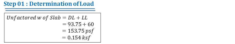
10 For Cantilever l = = 67 Multiplying factor, MF = = 0.8 Thickness = l 0.8 = Among the thickness maximum thickness = 5.36 Hence use 5.5 DETERMINING LOADS Consider only a 1 ft width of beam. Floor Finish = 25 psf Live load = 60 psf Dead load = /12=68.75 psf (Unit wt. of Concrete = 150 pcf) Factored DL and LL, wu =[( )x x1.6] psf = psf = 0.21 ksf DETERMINING MAXIMUM MOMENTS Moment coefficients at critical sections by ACI code: Figure 6: Moment Coefficient Page 7
11 At Section 1 : M u = 0 w u l 2 = 0 k ft/ft = 0 k in/ft At Section 2 : M u = 1 11 w ul 2 = 2.35 k ft/ft = 28.2 k in/ft At Section 3 (Left) :M u = 1 12 w ul 2 = 2.15 k ft/ft = 25.8 k in/ft At Section 3 (Right) : M u = 1 12 w ul 2 = 2.15 k ft/ft = 25.8 k in/ft At Section 3 (Max.) : M u = 25.8 k in/ft At Section 4 : M u = 1 11 w ul 2 = 2.35 k ft/ft = 28.2 k in/ft At Section 5 (Left) : M u = 1 11 w ul 2 = 2.35 k ft/ft = 28.2 k in/ft At Section 5 (Right) : M u = 1 2 w ul 2 = 3.27 k ft/ft = k in/ft At Section 5 (Max.) : M u = k in/ft Maximum Moment (Only Value) : M max = k in/ft (For all Sections) MINIMUM EFFECTIVE DEPTH ρ = 0.85β 1 f c f y ε u ε u + ε t ρ = ρ = 0.85β 1 f c f y ε u ε u ρ = ρ = = d req = M max ρf y b (1 0.59ρ f y f c ) = ( ) = 2.31 in Page 8
12 CHECKING AVAILABILITY OF THICKNESS As required effective depth, dreq is less than provided effective depth, dprov. of ( ) = 4.50 in, the thickness of 5.50 in can be adopted. MINIMUM REINFORCEMENT AREA A s,min = bt = ( ) in 2 /ft = 0.13 in 2 /ft Minimum reinforcement of 0.13 in 2 /ft should be provided at every section. REINFORCEMENT AREA DETERMINATION AT ALL SECTIONS A s = At Section 1: (Mu = 0 k-in/ft) Let, a = 1 in A s = = and, a = a = M u f y (d a/2) (4.5 1/2) = 0 in 2 /ft A sf y 0.85f c b = 0 in Again, A s = = M u f y (d a/2) (4.5 0/2) M u f y (d a/2) & a = A sf y 0.85f c b = 0 in 2 /ft (Same as before)(but As < As,min) = in 2 /ft Page 9
13 At Section 2: (Mu = 28.2 k-in/ft) Let, a = 1 in M u A s = f y (d a/2) = and, a = a = (4.5 1/2) = 0.2 in 2 /ft A sf y 0.85f c b = 0.26 in Again, A s = = and, a = a = M u f y (d a/2) ( /2) = 0.18 in 2 /ft A sf y 0.85f c b = 0.24 in Again, A s = = M u f y (d a/2) ( /2) = 0.18 in 2 /ft (Same as before)(here, As > As,min), OK Page 10
14 At Section 3: (Mu = 25.8 k-in/ft) Let, a = 1 in M u A s = f y (d a/2) = and, a = a = (4.5 1/2) = 0.18 in 2 /ft A sf y 0.85f c b = 0.24 in Again, A s = = and, a = a = M u f y (d a/2) ( /2) = 0.16 in 2 /ft A sf y 0.85f c b = 0.21 in Again, A s = = M u f y (d a/2) ( /2) = 0.16 in 2 /ft (Same as before)(here, As > As,min), OK Page 11
15 At Section 4: (Mu = 28.2 k-in/ft) Let, a = 1 in M u A s = f y (d a/2) = and, a = a = (4.5 1/2) = 0.2 in 2 /ft A sf y 0.85f c b = 0.26 in Again, A s = = and, a = a = M u f y (d a/2) ( /2) = 0.18 in 2 /ft A sf y 0.85f c b = 0.24 in Again, A s = = M u f y (d a/2) ( /2) = 0.18 in 2 /ft (Same as before)(here, As > As,min), OK Page 12
16 At Section 5: (Mu = k-in/ft) Let, a = 1 in M u A s = f y (d a/2) = and, a = a = (4.5 1/2) = 0.27 in 2 /ft A sf y 0.85f c b = 0.35 in Again, A s = = and, a = a = M u f y (d a/2) ( /2) = 0.25 in 2 /ft A sf y 0.85f c b = 0.33 in Again, A s = = M u f y (d a/2) ( /2) = 0.25 in 2 /ft (Same as before)(here, As > As,min), OK Page 13
17 Figure 7: Reinforcement Area Required REINFORCEMENT SPACING DETERMINATION Short Direction: S min = 1.5t = = 8.25" S max = 3t or 18=(3 5.5)" or 18" =16.5" or 18" = 16.5" (Lower one) A s = in 2 /ft (If #3 is provided) (At Section 2 & Section 4) 0.18 in 2 reinforcement required in 12 inch 1 in 2 reinforcement required in inch 0.11 in 2 reinforcement required in inch But, S < S min (not Ok) = 7.33" 7" (0.5" lower rounding) A s = in 2 /ft (If #4 is provided) (At Section 2 & Section 4) 0.18 in 2 reinforcement required in 12 inch 1 in 2 reinforcement required in inch 0.2 in 2 reinforcement required in inch = 13.33" 13" (0.5" lower rounding) Now, S min < S < S max (Ok) A s = in 2 /ft (At Section 1) c/c alt. ckd 26" c/c is already provided In 26 inch already provided reinforcement area = 0.2 in 2 Page 14
18 In 12 inch required reinforcement area = 0.13 in 2 In 1 inch required reinforcement area = In 26 inch required reinforcement area = 0.28 in 2 Extra reinforcement required = ( ) =0.08 in 2 No. of extra top bar required (if # 3 bar is used) = = A s = in 2 /ft (At Section 3) in 2 1#3 extra top between ckd. bar 26" c/c is already provided In 26 inch already provided reinforcement area = 0.2 in 2 In 12 inch required reinforcement area = 0.16 in 2 In 1 inch required reinforcement area = In 26 inch required reinforcement area = 0.35 in 2 Extra reinforcement required = ( ) =0.15 in 2 No. of extra top bar required (if # 4 bar is used) = = A s = in 2 /ft (At Section 5) in 2 1#4 extra top between ckd. bar 26" c/c is already provided In 26 inch already provided reinforcement area = 0.2 in 2 In 12 inch required reinforcement area = 0.25 in 2 In 1 inch required reinforcement area = In 26 inch required reinforcement area = 0.54 in 2 Extra reinforcement required = ( ) =0.34 in 2 No. of extra top bar required (if # 4 bar is used) = = in 2 2#4 extra top between ckd. bar Page 15
19 Long Direction: S min = 1.5t = = 8.25" S max = 5t or 18=(5 5.5)" or 18" =27.5" or 18" = 18" (Lower one) A s,min = 0.13 in 2 /ft A s = in 2 /ft 0.13 in 2 reinforcement required in 12 inch 1 in 2 reinforcement required in inch 0.11 in 2 reinforcement required in inch = 10.15" 10" (0.5" lower rounding) Now, S min < S < S max (Ok) DETAILING: c/c Figure 8: Detailing at Plan Page 16
20 Figure 9: Detailing at Section 1-1 Figure 10: Detailing at Section 2-2 Page 17
21 2. DESIGN OF BEAM (USD) Introduction: Ultimate Strength Design (USD) Based on the ultimate strength of the structure, assuming a failure condition either due to concrete crushing or by yielding of steel. Additional strength of steel due to strain hardening is not encountered in the analysis or design. Actual / working loads are multiplied by load factor to obtain the design loads. ACI codes emphasizes this method. Assumptions: There are five assumption that are made 1. Plane sections before bending remain plane after bending. 2. Strain in concrete is the same as in reinforcing bars at the same level, provided that the bond between the steel and concrete is sufficient to keep them acting together under the different load stages i.e., no slip can occur between the two materials. 3. The stress-strain curves for the steel and concrete are known. 4. The tensile strength of concrete may be neglected. 5. At ultimate strength, the maximum strain at the extreme compression fiber is assumed equal to Design and Analysis The main task of a structural engineer is the analysis and design of structures. The two approaches of design and analysis will be used. Design of a section: This implies that the external ultimate moment is known, and it is required to compute the dimensions of an adequate concrete section and the amount of steel reinforcement. Concrete strength and yield of steel used are given. Analysis of a section: This implies that the dimensions and steel used in the section (in addition to concrete and steel yield strengths) are given, and it is required to calculate the internal ultimate moment capacity of the section so that it can be compared with the applied external ultimate moment. Beam Types Singly reinforced section Doubly reinforced section Page 18
22 Flexure Équations Figure 12: Diagrams for flexure equations A s bd FAILURE MODES No Reinforcing Brittle failure Reinforcing < balance Steel yields before concrete fails ductile failure Reinforcing = balance 200 min f y 0. max 75 bal bal 0.85 f y f ' 1 c f y Concrete fails just as steel yields Reinforcing > balance Concrete fails before steel yields max Page 19
 133 24 = 7315 32 ft2 Page")
23 DESIGN EXAMPLE OF BEAMS Load Calculation for Beam Design Figure 12: Beam Layout Figure 13: Determination of Contributing Area for Load Calculation Controlling Area = ( ) = ft2 Page 20


24 Bending Moment and Shear Force Diagram for Beam Design Reactions at supports: (Assume the beam to have the following support conditions) Figure 14: Determination Support Reactions SFD and BMD Page 21

25 Figure 15: Shear Force Diagram and Bending Moment Diagram d check for Maximum Moment FLEXURAL REINFORCEMENT AREA DETERMINATION: Page 22
 A")
")

26 A s = 1.85 in 2 (2#6 & 1#9) A s = 3.48 in 2 (2#10 & 1#9) SHEAR REINFORCEMENT DETERMINATION Figure 16: Shear Force Diagram of Beam Page 23

27 Figure 17: Distance determination where V u = V c Page 24


28 Detailing of Beam Reinforcement Figure 18: Beam Reinforcement Detailing Guideline Figure 19: Beam Reinforcement Detailing According to the Design Page 25

29 3. DESIGN OF STAIR (USD) Figure 20: Stair Figure 21: Components of Stair Page 26

30 Figure 22: Parameters of Stair Page 27
31 Page 28
32 Page 29
33 Figure 23: Reinforcement Details of stair. Page 30
 Figure 24:")

34 4. DESIGN OF SUNSHADE (USD) Figure 24: Section and Side View of a Wall with Window Page 31


35 Figure 25: Detailing of Sunshade Page 32


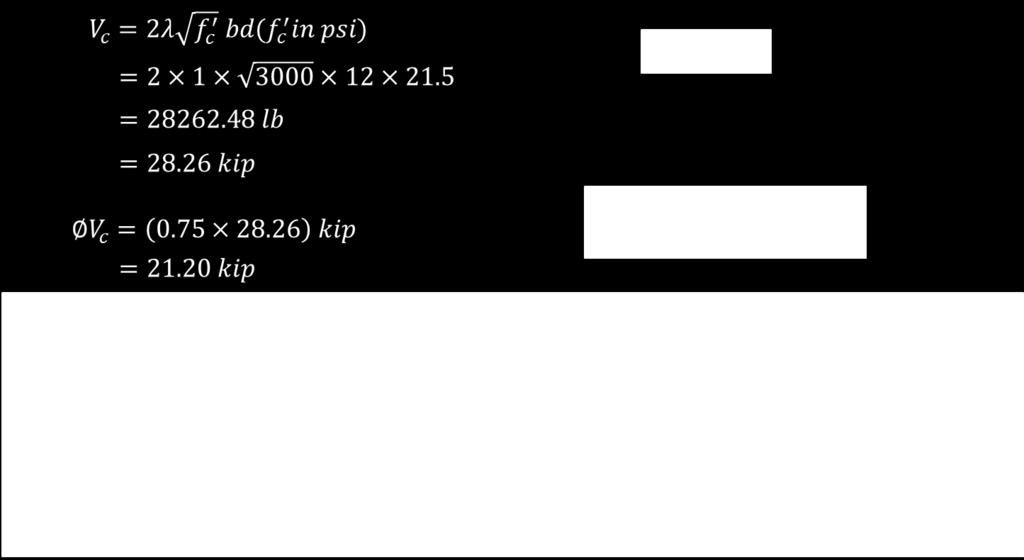
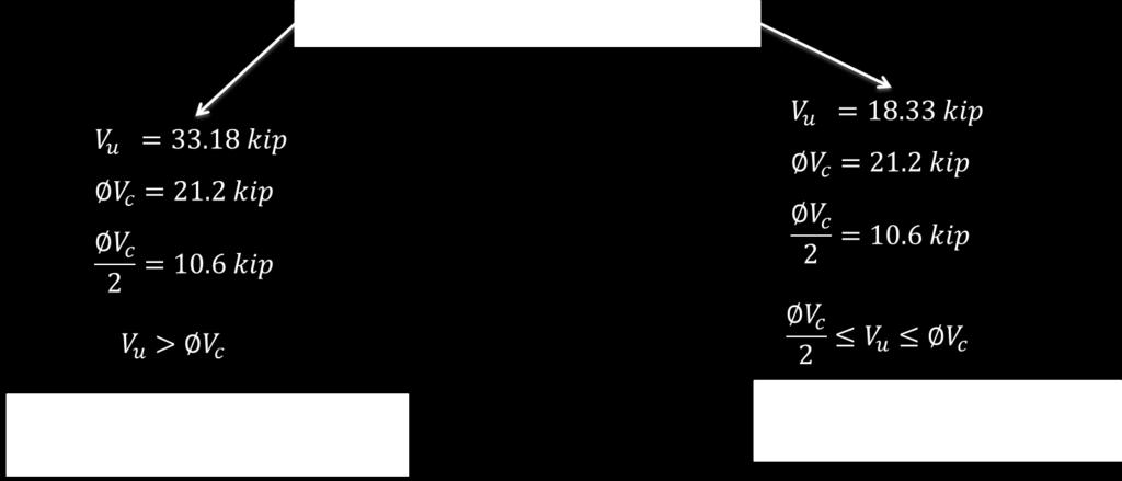
36 5. DESIGN OF LINTEL (USD) Figure 26: Information necessary to determine lintel load Figure 27: Loads come to Lintel from Slab Page 33
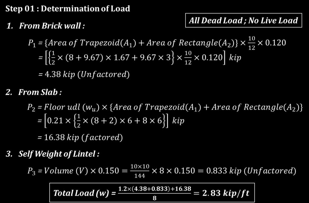
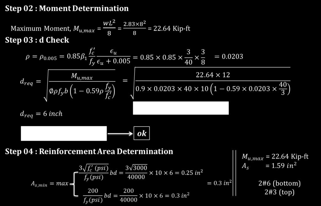
37 Page 34


38 Figure 28: Detailing of Lintel Page 35
39 6. DESIGN OF BRICK FOUNDATION (WSD) Design of brick foundation requires study and examination of multiple components, and it is the main structure of any building, since it is the base of it. Foundation Depths The required depth of the foundation will depend on several factors like: 1. Soil bearing capacity: How much load the existing soil can withstand. 2. Type of soil: This depth will vary depending on the type of soil beneath the structure. 3. Depth of frost penetration in case of fine sand and silt. 4. Height of ground water table: This will usually be reported on the soil study. 5. The minimum depth should not be less than 18 inches to allow removal of top soil and variations in ground level. However, depending on the structure, the engineer will select the best depth. Foundation Material The foundation is usually built in brick work, masonry or concrete under the base of a wall or column. This will enable to transfer the load to the soil in a uniform manner and allow the transition from the structure to the soil. It will depend on the recommendation by the structural engineer. For smaller and lightweight structures, the design will be different depending on the material and location of the structure. Usually dry and uniform graded dense materials should have maximum shear resistance and maximum bearing capacity. In general submerged soil and clay have fewer bearing capacities, reducing the capacity to handle loads imposed by the structure. Foundation Design Precaution The foundation will be designed in a way that loads will be transferred uniformly to the contact surface. It should be designed to transmit the sum of dead load, live load and wind load to the ground. The net loading capacity coming into the soil should not exceed the bearing capacity of the soil. Settlements expected from the building will be design in such way that they will be controlled and uniform for the complete structure to avoid damages to the structure. Whole design of the foundation, super structure and characteristics of the ground should be studied to obtain benefits during construction work. Page 36
 k. Generally 10%-12% is considered as first assumption. For this example 10% load of superstructure is added as self-weight.")
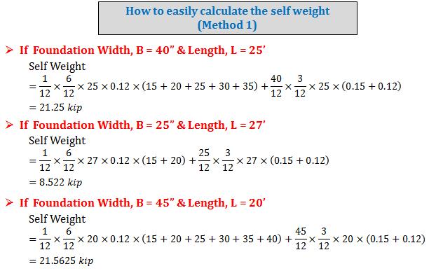
40 Figure 29: Typical Brick Foundation Design Procedure 1. Find the total load on foundation. Suppose the load is 135k considering all load of superstructure on that particular foundation. Then the total load P is (135+Self weight of the foundation under G.L) k. Generally 10%-12% is considered as first assumption. For this example 10% load of superstructure is added as self-weight. So the total load P is ( ) = k 2. Find the soil bearing capacity. Suppose soil bearing capacity is 3 ksf Then the width of the foundation is B = soil bearing capacity length of the foundation = where length of the foundation is 22.5 ft = 26.4 inch required width but in brick foundation width must be rounded to upper 5". So width for this foundation is 30". 3. Check the self-weight of the foundation whether it is less than the assumed value. If it is less than the design is ok. Page 37

41 DESIGN EXAMPLE OF FOUNDATION Figure 30: Contributing area of slab on brick wall Figure 31: Loads on Foundation Page 38
42 Page 39

43 Page 40

44 Design of a slab bridge Page 41
45 Design of a slab bridge Data and Specifications Clear Span Clear width Live Loading Wearing surface Concrete strength f c 15 ft 26 ft HS20 30 psf 3000 psi Grade 40 reinforcement By AASHTO specifications, an allowable concrete stress of f c = 0.40 f c = 1200 psi Slab Design Assume trial slab thickness, t = 12 in And an allowable steel stress of f s = 0.5 f y = 20,000 psi will be used The effective span of the slab,s = = 16 ft [for simple span the span length shall be the distance of center to center of supports but shall not exceed clear span plus thickness of slab] Total dead load = (t/12)*150 + wearing surface = 180 psf For a strip of 1 ft width W dl = 180 lb/ft Dead load moment, DLM = W dl S 2 /8 = 180*16*16/8 = 5760 ft-lb Total load on each rear wheel, P 20= lb [for HS20 truck loading] Width of slab over which wheel load is distributed,e = S [ for main reinforcement parallel to traffic] = *16 = 4.96 ft The load on unit width of slab, P = P 20/E =16000/4.96 =3230 lb Page 42
46 Live load moment, LLM = PS/4 =3230*16/4 Impact coefficient, I = = ft-lb 50 l Where l is the loaded length which is equal to effective span, S here 50 I = S+125 = 0.355>0.3 So I will be taken as 0.3 Impact moment, IM = Impact coefficient*live load moment = I*LLM =0.3*12900 =3870 ft-lb Total moment,m = DLM+LLM+IM =22,530 ft-lb The design will be based on service load and the slab will be proportioned based on the cracked elastic section k = n n + r Use n = 10 and r = fs/fc k= j = 1-k/3= effective depth, d reqd = 2M = 10.7 in fckjb d provided = t-protective cover-half of main bar dia = [by providing #8 bar] = 10.5 Page 43
47 dprovidedis sufficiently close to dreqd Reinforcement Calculation: The required main reinforcement, As= M = = 1.47 fsjd in2 /ft This is furnished by #8 bars 6 in on centers Transverse reinforcement For main reinforcement parallel to traffic transverse reinforcement Ast= As S = 0.37in 2 #5 bars 10 in on centers are directly placed on top of the longitudinal reinforcement. Curb design To facilitate screeding off the slab the required curb will not be made monolithically. The dead load carried by the edge beam = = 550 plf 144 Dead load moment = 550*16 2 /8 = ft-lb The specified live load moment = 0.1*P20*S = 0.1*16000*16 = ft-lb Total moment = = ft-lb The resisting moment of the given section,mr = 0.5fckjbd 2 Which is adequate The steel required,as = Which will be provided by three No. 7 bar = 1.44 in2 = 0.5*1200*0.375*0.875*24* /12= ft-lb Page 44
48 2'-0" #5 3" 2'-0" 12" 1'-6" 15'-0" 1'-6" Longitudinal Section 3" bituminous surface Crown 1¼ 2 - #5 10" 12" Symmetrical about Center line #8@6" 13'-0" Tranverse Section #5@10" 2'-0" 3 - #7 Page 45

49 Design of a Deck Girder bridge Page 46
50 Design of a Deck Girder bridge Data and Specifications Clear Span Clear width Live Loading Concrete strength f c Future protective cover 48 ft 29 ft HS psi 15 pf Grade 40 reinforcement The bridge will consist of six girders By AASHTO specifications, an allowable concrete stress of f c = 0.40 f c = 1200 psi And an allowable steel stress of f s = 0.5 f y = 20,000 psi will be used 2' 48' 2' Bridge Profile Page 47
51 Slab Design Span = clear distance between girders [The slab will be poured monolithically with the girder and fully continuous] Assume the girder width = 14 and total slab thickness = 6 [including ¾ in wearing surface] Clear span,s = 4 ft 4 in Total dead load, W dl = 6/12* = 90 psf A coefficient of 1 will be used for both positive and negative moment 10 2'-0" 14'-6" 10" 6.5" 2'-9" 5'-6" 5'-6" 2'-9" Dead load moment, DLM = W dl S 2 /10 = 1 10 *90*4.332 = 169 ft-lb Transverse Section Total load on each rear wheel, P 20= lb [for HS20 truck loading] Page 48
52 Live load moment, LLM = S+2 32 P20 [for main reinforcement perpendicular to traffic] For slabs continuous over three or more supports a continuity factor of 0.8 shall be applied to the above formula Live load moment, LLM = S+2 32 P20 Impact coefficient, I = = 0.8* *16000 = 2530 ft-lb 50 l Where l is the loaded length which is equal to clear span, S here So I will be taken as I = S+125 = 0.387>0.3 Impact moment, IM = Impact coefficient*live load moment = I*LLM =0.3*2530 =760 ft-lb Total moment,m = DLM+LLM+IM =3459 ft-lb The design will be based on service load and the slab will be proportioned based on the cracked elastic section k = n n + r Use n = 10 and r = fs/fc k= j = 1-k/3= effective depth, d reqd = 2M = 4.19 in fckjb Page 49
53 d provided = t-protective cover-half of main bar dia = * [by providing #6 bar, 1 in protective cover and ¾ wearing surface] = in dprovided is lower than dreqd So 6.5 in slab will be used Reinforcement Calculation: The required main reinforcement, As= M = fsjd = 0.54 in2 /ft This is furnished by #6 bars 10 in on centers Transverse reinforcement For main reinforcement perpendicular to traffic transverse reinforcement Ast= 2.20As S = 0.57 in 2 > 0.67* As = 0.36 in 2 #5 bars 10 in on centers are directly placed on top of the longitudinal reinforcement. Page 50
54 Interior Girder Design Interior girders are T beams with a flange width equal to the center to center distance of girders [ based on ACI code] Total moment calculation is done by following the steps listed below: 1. Dead load moment calculation: a. Calculate total load from slab and assumed 14 X30 stem (below the slab)in plf b. Calculate maximum dead load moment DLMmax[the girder will act like a simply supported beam with uniformly distributed load] c. Calculate DLM at one quarter and two quarter points of the span. 2. Live load moment calculation: For live load moment calculation both truck load moment and lane loading moment needed to be calculated. Based on this calculation the governing Live Load Moment, LLMmaxhas to be decided. Live load moment at one quarter and two quarter points of the span have to also be calculated. 3. Impact moment calculation: Impact moment, IM max = Impact coefficient*live load moment Impact moment at one quarter and two quarter points of the span have also to be calculated. Total Moment = DLMmax+ LLMmax+ IM max Total moment moment at one quarter and two quarter points of the span have also to be calculated. Total shear calculation is done by following the steps listed below: 1. Dead load shear calculation: Calculate maximum dead load shear at the end of the beam and at atone quarter and two quarter points of the span of the beam. Page 51
55 2. Live load shear calculation: Calculate maximum live load shear for truck loading and lane loading at the end of the beam and atone quarter and two quarter points of the span of the beam. Based on the above calculation decide the governing Live load shear. 3. Impact shear: Impact shear, IS = Impact coefficient*live load shear Impact shear at one quarter and two quarter points of the span have also to be calculated. Total shear (63400 psi) at the end of the beam and at one quarter and two quarter points of the span have to be calculated. Determination of cross section and steel area According to AASHTO specification Nominal shear stress at service load, v = V/bwd Where bw = width of web. In beam with web reinforcement the nominal shear stress, v may not exceed 4.95 fc In sizing the web area maximum shear force of 2.95 fc = 162 psi will be used bwd = V v = 63, = 391 in2 asbw = 14 in, drequired = 28 in if three rows of #11 bars are used with 2 in clear between rows and 2.5 in clear below the bottom row to allow for stirrups and concrete protection a total depth of in ( *11/8) is obtained. A total depth of 36 in will be used. The depth of the stem below the slab is then = 29.5 in which is so close to the assumed value that the dead load moments need not be revised. The next step is tensile steel area calculation and web reinforcement calculation. The final step is bar cut off Page 52
56 Exterior Girder Design The exterior girders are identical in cross section with the interior girders cause the raised curb section will be poured separately and cannot be counted in to participate in carrying loads. Moment Calculation: In addition to the total dead load obtained for the interior girders the safety curbs will add some extra load (total 1215 plf). By following the same procedure total moment and shear have to be calculated. A portion of the wheel load which rests on the exterior slab panel is supported by the exterior girder. That portion is obtained by placing the wheels as close to the curb as the clearance diagram will permit and treating the exterior slab panel as a simple beam. The portion is shown in the following fig and the proportion of the load is 4.25/5.5 = '-6" 2'-0" 6'-0" 2'-0" 2'-9" 5'-6" 4'-3" 5'-6" 1'-3" 2'-9" Lateral Position of Wheel The absolute maximum live load moment = * = ft-lb 1.1 The impact moment is 0.285* = ft-lb and the total maximum moment is ft-lb. Page 53
57 Shear Calculation: The maximum dead load shear is V D = 1215*25 = lb The maximum live load shear is proportional to the maximum live load shear in interior girder V L = *30600 = lb The impact shear is 6100 lb. The total shear at the support is then lb. Shear at other points are found similarly. Determination of cross section and reinforcement: Once the shears and moments due to dead loads, live loads and impact are obtained the design of the exterior girders would follow along the lines of that of interior girders. 12" diaphragm 3" #5 U stirrup 13@9"=9'-9" 12@15"=15'-0" 5@20" = 8'-4" 2#6 12" diaphragm 6.5" 36" 4#11 4#11 3#11 2'-2" 8'-8" Details of Interior Girder Page 54
58 Diaphragms: A transverse will be built between the girders at either end of the bridge. The chief function of these diaphragm is to furnish lateral support to the girders, with some abutment details it also serve to prevent the backfill from spilling out onto the bridge seats. A similar diaphragm will be built between girders at midspan. Such intermediate diaphragms are required for all spans in excess of 40 ft and serve to ensure that all girders act together in resisting loads. Fixed bearing is provided at one end and expansion bearing is provided at the other end. Water proofing and drainage: all joints will be filled with a mastic compound to prevent water from seeping through the joints. Crowing is provided for quick drainage of the rain water. Page 55
59 REFERENCES Bangladesh National Building Code (BNBC), Arthur H. Nilson, David Darwin and Charles W. Dolan, Design of Concrete Structures, 13 th Edition, Mc-Graw Hill Publication. Arthur H. Nilson, David Darwin and Charles W. Dolan, Design of Concrete Structures, 7 th Edition, Mc-Graw Hill Publication. Design of RCC Members by WSD and USD Methods, Public Works Department (PWD), Sushil Kumar, 2001, Building Construction, 19 th Edition, Standard Publishers Distribution, New Delhi. Neville, A.M., Concrete Technology. Page 56
VARIOUS TYPES OF SLABS
 VARIOUS TYPES OF SLABS 1 CHOICE OF TYPE OF SLAB FLOOR The choice of type of slab for a particular floor depends on many factors. Economy of construction is obviously an important consideration, but this
Analysis and Design of One-way Slab System (Part-I)
") Lecture-02 Analysis and Design of One-way Slab System (Part-I) By: Prof Dr. Qaisar Ali Civil Engineering Department UET Peshawar www.drqaisarali.com 1 Topics Addressed Concrete Floor Systems Analysis and
Lecture-02 Analysis and Design of One-way Slab System (Part-I) By: Prof Dr. Qaisar Ali Civil Engineering Department UET Peshawar www.drqaisarali.com 1 Topics Addressed Concrete Floor Systems Analysis and
Design of Reinforced Concrete Slabs
 Lecture 07 Design of Reinforced Concrete Slabs By: Prof Dr. Qaisar Ali Civil Engineering Department UET Peshawar drqaisarali@uetpeshawar.edu.pk 1 Topics Addressed Introduction Analysis and Design of slabs
How Loads Are Distributed
 LOAD DISTRIBUTION 1 LOAD DISTRIBUTION This section illustrate how load will transmit from the deck to the stringers. Determining the fraction of load carried by a loaded member and the remainder distributed
Agricultural Hall and Annex East Lansing, MI. Structural Design. Gravity Loads. 1- Based on US Standards
 Structural Design Gravity Loads 1- Based on US Standards Occupancy or Use Uniform (psf) Concentrated (lbs) Office building -Office -Lobbies and first-floor corridors -Corridor above first floor -Partitions
VOL I: Bridge Design & Load Rating
 PRESERVATION OF MISSOURI TRANSPORTATION INFRASTRUCTURES VOL I: Bridge Design & Load Rating VALIDATION OF FRP COMPOSITE TECHNOLOGY THROUGH FIELD TESTING Strengthening of Bridge X-495 Iron County, MO Prepared
One-Way Wide Module Joist Concrete Floor Design
 One-Way Wide Module Joist Concrete Floor Design A 1 3 4 30'-0" 30'-0" 30'-0" 3' B 3' C 3' D 3' E 4" 4" (typ.) 3' F 0" 0" (typ.) Figure 1 One-Way Wide Module Joist Concrete Floor Framing System 1 Overview
Alternate Design Method- Design Procedure of Two-way Slabs using ACI Moment Coefficients and Approved by BNBC 2013
 Alternate Design Method- Design Procedure of Two-way Slabs using ACI Moment Coefficients and Approved by BNBC 2013 Scope and Limitations (BNBC) 6.5.8.2.1 The provisions of this section may be used as alternative
Figure: Grid or Waffle slab
 Two Way Beam Supported Slab References: 1. Design of. Reinforced Concrete, 2014, 9 th Edition, ACI 318-11 Code Edition, by Jack C. McCormac. Clemson University. Russell H. Brown. Clemson University 2.
Parapet/railing terminal walls shall be located on the superstructure.
 GENERAL INFORMATION: This section of the chapter establishes the practices and requirements necessary for the design and detailing of deck slab extensions at abutments. For general requirements and guidelines
Ce 479 Reinforced Masonry Fall 2005
 INTRODUCTION TO STRUCTURAL DESIGN OF REINFORCED MASONRY In the preceding lecture on structural design of masonry, we have seen examples of unreinforced masonry bearing walls. In bearing walls, when the
Section A A: Slab & Beam Elevation
 CE 331, Spring 2011 Flexure Strength of Reinforced Concrete s 1 / 5 A typical reinforced concrete floor system is shown in the sketches below. The floor is supported by the beams, which in turn are supported
STRONGWELL GRIDFORM SLAB DESIGN MANUAL
 STRONGWELL GRIDFORM SLAB DESIGN MANUAL LAWRENCE C. BANK MICHAEL G. OLIVA JEFFREY J. BRUNTON VERSION 2 JANUARY 1, 2011 Table of Contents 1 INTRODUCTION 4 2 GENERAL DESIGN NOTES 5 3 INPUT SHEET 5 3.1 Design
STRONGWELL GRIDFORM SLAB DESIGN MANUAL
 STRONGWELL GRIDFORM SLAB DESIGN MANUAL LAWRENCE C. BANK MICHAEL G. OLIVA JEFFREY J. BRUNTON VERSION 1 AUGUST 31, 2009 Table of Contents 1 INTRODUCTION 4 2 GENERAL DESIGN NOTES 5 3 INPUT SHEET 5 3.1 Design
Continuous Beam Design with Moment Redistribution (ACI )
") Continuous Beam Design with Moment Redistribution (ACI 318-14) Continuous Beam Design with Moment Redistribution (ACI 318-14) A structural reinforced concrete continuous beam at an intermediate floor level
Continuous Beam Design with Moment Redistribution (ACI 318-14) Continuous Beam Design with Moment Redistribution (ACI 318-14) A structural reinforced concrete continuous beam at an intermediate floor level
DESIGN OF SLABS. 3) Based on support or boundary condition: Simply supported, Cantilever slab,
 Based on support or boundary condition: Simply supported, Cantilever slab,") DESIGN OF SLABS Dr. G. P. Chandradhara Professor of Civil Engineering S. J. College of Engineering Mysore 1. GENERAL A slab is a flat two dimensional planar structural element having thickness small compared
DESIGN OF SLABS Dr. G. P. Chandradhara Professor of Civil Engineering S. J. College of Engineering Mysore 1. GENERAL A slab is a flat two dimensional planar structural element having thickness small compared
EGCE 406: Bridge Design
 EGCE 406: Bridge Design Design of Slab for Praveen Chompreda Mahidol University First Semester, 2006 Bridge Superstructure Outline Components of bridge Superstructure Types Materials Design of RC Deck
A Guide for the Interpretation of Structural Design Options for Residential Concrete Structures
 CFA Technical Note: 008-2010 A Guide for the Interpretation of Structural Design Options for Residential Concrete Structures CFA Technical This CFA Technical Note is intended to serve as a guide to assist
CHAPTER 9 STAIR CASES 9.1 GENERAL FEATURES 9.2 TYPES OF STAIR CASES
 CHAPTER 9 STAIR CASES 9.1 GENERAL FEATURES Stair cases are provided for connecting successive floors. It is comprised with flights of steps with inter mediate landings which provides rest to the user and
Effect of Edge Beam and Shear Wall on the Structural Behavior of Flat Plate Multistoried Building: A Computing Modeling for lateral load Analysis
 Effect of Edge Beam and Shear Wall on the Structural Behavior of Flat Plate Multistoried Building: A Computing Modeling for lateral load Analysis Zasiah Tafheem 1, A.S.M Rubaiat Nahid 2, Tanzeelur Rahman
BrD Superstructure Tutorial
 AASHTOWare BrD 6.8 BrD Superstructure Tutorial PS12 Prestressed Concrete I Beam Using BrD LRFD Engine BrD Superstructure Training PS12 - Prestressed Concrete I Beam Using BrD LRFD Engine 1'-9" 55'-6" Total
Lecture-06 Analysis and Design of Slab Systems
 Lecture-06 Analysis and Design of Slab Systems By: Prof Dr. Qaisar Ali Civil Engineering Department UET Peshawar drqaisarali@uetpeshawar.edu.pk www.drqaisarali.com 1 Topics Addressed Organization of the
CHAPTER 2. Design Formulae for Bending
 CHAPTER 2 Design Formulae for Bending Learning Objectives Appreciate the stress-strain properties of concrete and steel for R.C. design Appreciate the derivation of the design formulae for bending Apply
Prestress Superstructure Tutorial
 AASHTOWare BrDR 6.8.2 Prestress Superstructure Tutorial PS14 Prestressed Concrete I Beam Example PS14 - Prestressed Concrete I Beam Example This example details the data input of a prestressed concrete
CE2401-DESIGN OF REINFORCED CONCRETE AND BRICK MASONRY QUESTION BANK
 CE2401-DESIGN OF REINFORCED CONCRETE AND BRICK MASONRY QUESTION BANK UNIT-1 PART-A 1. What is a Retaining wall? 2. What are the disadvantages of gravity retaining walls? 3. What are the types of retaining
MASONRY WALL DATA: Wall Height = ft. Nominal Wall Thickness = 8.00 in. Depth to c.g. Steel, Wall = 3.81 in.
 TIME: 10:49 AM Page: 1 DESIGN METHOD : ACI 530-99: Working Stress Design MASONRY MATERIAL : Hollow Core Concrete Masonry Units MORTAR TYPE : Type S MORTAR MATERIAL : Portland Cement Lime Mortar BLOCK PLACEMENT
V Slab Bridge Design Software, Version 4.0 Superstructure Design Check
 V Slab Bridge Design Software, Version 4.0 This superstructure design check is provided to assist the designer in understanding the key program functions and associated design calculations. This is intended
Alexis Pacella Structural Option Dr. Schneider Lexington II, Washington D.C. Technical Report #2 October 31,
 1 Executive Summary: Pro-Con Structural Study of Alternate Floor Systems is an investigation into possible alternative structural systems for Lexington II in Washington, D.C. For this report, several structural
3.4.2 DESIGN CONSIDERATIONS
 3.4.2 DESIGN CONSIDERATIONS Formwork Where Flatdeck sheet is used as formwork, the profile provides resistance to wet concrete (G) and construction loads (Q). Maximum formwork spans given in Section 3.4.4.1
mortarless masonry Design Manual Part 1 (IS 456:2000) Section 1 Page 1 IS 456:2000 PLAIN AND REINFORCED CONCRETE - CODE OF PRACTICE
 Section 1 Page 1 IS 456:2000 PLAIN AND REINFORCED CONCRETE - CODE OF PRACTICE") SECTION 1. mortarless masonry Design Manual Part 1 (IS 456:2000) Section 1 Page 1 1.1 Overview of IS 456:2000 IS 456:2000 PLAIN AND REINFORCED CONCRETE - CODE OF PRACTICE IS 456:2000 is the current Indian
SECTION 1. mortarless masonry Design Manual Part 1 (IS 456:2000) Section 1 Page 1 1.1 Overview of IS 456:2000 IS 456:2000 PLAIN AND REINFORCED CONCRETE - CODE OF PRACTICE IS 456:2000 is the current Indian
ANALYSIS AND DESIGN OF MULTI-STOREY COMPOSITE BUILDING
 ANALYSIS AND DESIGN OF MULTI-STOREY COMPOSITE BUILDING Mr Nann Tin 1, Dr Tin Tin Win 2 1 Postgraduate Student, Department of Civil Engineering, Mandalay Technological University, Myanmar 2 Director, Myanma
Class Topics & Objectives
 EGCE 406: Bridge Design Design of Slab for Bridge Deck Praveen Chompreda, Ph.D. Mahidol University First Semester, 2010 Class Topics & Objectives Topics Objective Bridge Superstructures Students can identify
UNIT-1 RETAINING WALLS
 UNIT-1 RETAINING WALLS PART-A 1. Describe about Retaining wall. 2. Define gravity retaining walls. BT-1 3. Classify the types of retaining walls. 4. Explain cantilever retaining wall? 5. Describe about
SIDDHARTH GROUP OF INSTITUTIONS :: PUTTUR Siddharth Nagar, Narayanavanam Road QUESTION BANK (DESCRIPTIVE)
") SIDDHARTH GROUP OF INSTITUTIONS :: PUTTUR Siddharth Nagar, Narayanavanam Road 517583 QUESTION BANK (DESCRIPTIVE) Subject with Code : DDRCS(13A01502) Year & Sem: III-B.Tech & I-Sem Course & Branch: B.Tech
SIDDHARTH GROUP OF INSTITUTIONS :: PUTTUR Siddharth Nagar, Narayanavanam Road 517583 QUESTION BANK (DESCRIPTIVE) Subject with Code : DDRCS(13A01502) Year & Sem: III-B.Tech & I-Sem Course & Branch: B.Tech
Flexure Design Sequence
 Prestressed Concrete Beam Design Workshop Load and Resistance Factor Design Flexure Design Flexure Design Sequence Determine Effective flange width Determine maximum tensile beam stresses (without prestress)
Atkinson Engineering, Inc.
 Atkinson Engineering, Inc. Atkinson Engineering, Inc. One of the problems in underpinning a typical post-tensioned foundation is support for the slab part that spans between the stiffening beams. An example
111 MORGAN ST. Ryan Friis
 Technical Report No. 1 September 30, 2002 Executive Summary: 111 Morgan St. is a 9 story cast-in-place concrete condominium building being constructed in Chicago, Illinois. The building s floor system
Reinforced Concrete Design. A Fundamental Approach - Fifth Edition
 CHAPTER REINFORCED CONCRETE Reinforced Concrete Design A Fundamental Approach - Fifth Edition Fifth Edition REINFORCED CONCRETE A. J. Clark School of Engineering Department of Civil and Environmental Engineering
LEARNING OF ETABS. 15 ft
 LEARNING OF ETABS Ram Krishna Mazumder, Institute of Earthquake Engineering Research, Chittagong University of Engineering and Technology, Chittagong 4349, Bangladesh rkmazumder@gmail.com +8801712862281
Table of Contents.2. Introduction...3 Gravity Loading and Deflections..4. Existing Structural System..8
 WISCONSIN PLACE RESIDENTIAL TECHNICAL ASSIGNMENT 2 OCTOBER 29, 2007 KURT KRASAVAGE THE PENNSYLVANIA STATE UNIVERSITY STRUCTURAL OPTION FACULTY ADVISOR: DR. ALI MEMARI 1 Table of Contents Table of Contents.2
Structural Technical Report 1 Structural Concepts / Structural Existing Conditions Report
 Michael A. Troxell Structural Option Advisor: Professor Parfitt College of Business Administration Oct. 5, 2005 Structural Technical Report 1 Structural Concepts / Structural Existing Conditions Report
CONCRETE TECHNOLOGY CORPORATION
 PRECAST, PRESTRESSED HOLLOW CORE SLABS DESIGN CRITERIA & SPAN-LOAD CHARTS FOR STORM WATER DETENTION VAULT LIDS (CHARTS REVISED /18/08) Introduction Design Criteria for Development of the Span-Load Charts
Slab Bridge Designer 2.1 Help: Example Analysis
 August 21, 2006 Slab Bridge Designer 2.1 Help: Example Analysis Using data from the Portland Cement Association Engineering Bulletin 232, AASHTO LRFD Design of Cast-In-Place Concrete Bridges This example
Section G1. Design of Cast-In-Place Box Conduits
 G1-1 Economy of Design 1. Height to Width Ratio Section G1 Design of Cast-In-Place Box Conduits Careful economic studies should be made to determine the greatest economy of the entire storm drain. As an
CE 4460 Bridge Project Spring By: Megan Allain Bryan Beyer Paul Kocke Anna Wheeler
 CE 4460 Bridge Project Spring 2006 By: Megan Allain Bryan Beyer Paul Kocke Anna Wheeler Objective: Design a new I-10 bridge across Lake Ponchartrain Design according to LRFD and AASHTO 4 span segment design
Elimination of Deck Joints Using a Corrosion Resistant FRP Approach
 Elimination of Deck Joints Using a Corrosion Resistant FRP Approach Louisiana Transportation Conference February 2009 Aziz Saber, Ph.D., P.E. Chair of Civil Engineering Louisiana Tech University LTRC LA
Proposed Modifications to the LRFD Design of U-Beam Bearings
 Proposed Modifications to the LRFD Design of U-Beam Bearings Charles D. Newhouse, Scott A. Bole, W. R. Burkett, Phillip T. Nash, Mostafa El-Shami Performed in Cooperation with the Texas Department of Transportation
APPENDIX B ABC STRUCTURES DESIGN GUIDE
 APPENDIX B ABC STRUCTURES DESIGN GUIDE The Cohos Evamy Partners TABLE OF CONTENTS Page No. DISCLAIMER... I 1. STRUCTURAL DESIGN GUIDELINES... 1 2. GENERAL REQUIREMENTS (FIGURE B.2, STEP 1)... 1 3. GENERAL
Flexure and Serviceability Limit State
 UNIT 3 Flexure and Serviceability Limit State Beam A structural member that support transverse (Perpendicular to the axis of the member) load is called a beam. Beams are subjected to bending moment and
Stress-Laminated / Steel T-Beam Bridge System
 Stress-Laminated / Steel T-Beam Bridge System David A. Apple and Clinton Woodward, New Mexico State University Abstract The stress-laminated timber bridge deck has been successfully used for short span
ADAPT-PT 2010 Tutorial Idealization of Design Strip in ADAPT-PT
 ADAPT-PT 2010 Tutorial Idealization of Design Strip in ADAPT-PT Update: April 2010 Copyright ADAPT Corporation all rights reserved ADAPT-PT 2010-Tutorial- 1 Main Toolbar Menu Bar View Toolbar Structure
SPECIFICATIONS FOR THE CONSTRUCTION OF NEW PASSENGER EQUIPMENT CARS PREFACE
 SPECIFICATIONS FOR THE CONSTRUCTION OF NEW PASSENGER EQUIPMENT CARS Standard ADOPTED 1939; ADVANCED TO STANDARD, 1945. PREFACE The specifications have been prepared on the basis that they will be used
ACI Code Revisions Impact on StructurePoint Software
 ACI 318-19 Code Revisions Impact on StructurePoint Software General Themes & Summary ACI 318-19 continues to unify and simplify code provisions started in 2014 reorganization of chapters by members. Nearly
Development of Some Design Charts for Slab, Beam, Column and Flat Plate
 Banglavision ISSN: 2079-567X Vol. 13 No. 1 January 2014 Development of Some Design Charts for Slab, Beam, Column and Flat Plate Nitish Ranjan Gaine Nazma Khatun Suite Kumar Abstract The aim of this project
Check the strength of each type of member in the one story steel frame building below.
 CE 331, Summer 2015 nalysis of Steel Braced Frame Bldg 1 / 9 Check the strength of each type of member in the one story steel frame building below. 4 @ 8 ft B 20 f 1 2 3 @ 25 ft Side Elevation 3 4 Plan
USE OF 500 GRADE STEEL IN THE DESIGN OF REINFORCED CONCRETE SLAB. Prof. M. Shafiul Bari, Ph.D Department of Civil Engg., BUET
 1.0 Introduction USE OF 500 GRADE STEEL IN THE DESIGN OF REINFORCED CONCRETE SLAB Prof. M. Shafiul Bari, Ph.D Department of Civil Engg., BUET There is growing interest within the reinforced concrete industry
Design and analysis of T and inverted L beams- Theory and Examples
 Design and analysis of T and inverted L beams- Theory and Examples - Dr. E. R. Latifee Reference Book: Design of Reinforced Concrete by Jack C. McCormac and Russell H. Brown, Clemson University, 9 th Edition,
Sabah Shawkat Cabinet of Structural Engineering 2017
 3.3 Staircases Staircases provide means of movement from one floor to another in a structure. The effective span of a simply supported slab should normally be taken as the clear distance between the faces
Table of Contents 2. Structural Systems.4 Foundations.4 Floor System...4 Columns..5 Lateral System...5
 WISCONSIN PLACE RESIDENTIAL TECHNICAL ASSIGNMENT 1 OCTOBER 5, 2007 KURT KRASAVAGE THE PENNSYLVANIA STATE UNIVERSITY STRUCTURAL OPTION FACULTY ADVISOR: DR. ALI MEMARI Table of Contents Table of Contents
HORROCKS. Engineering Review of Proposed Cast-in-Place. Reinforced Arch Culvert Specification. For. Rinker Material Concrete Pipe Division
 JO7 For Engineering Review of Proposed Cast-in-Place SPECS Item #6 December 12, 2018 Handout Date: December11, 201$ Prepared By: PLK Reviewed By: DAA HORROCKS PROJECT NO. 18001 Phase 27 Rinker Material
CIVIL ENGINEERING YEAR QUESTION BANK
 CE 6505-DESIGN OF RC ELEMENTS CIVIL ENGINEERING SEM- V YEAR 2015-16 STAFF NAME: THIVAKAR.S A/P QUESTION BANK Subject Name: DESIGN OF RC ELEMENTS Subject Code: CE6505 PART-A UNIT I 1. What are the advantages
Continuous Beam Design with Moment Redistribution (CSA A )
") Continuous Beam Design with Moment Redistribution (CSA A23.3-14) Continuous Beam Design with Moment Redistribution (CSA A23.3-14) A structural reinforced concrete continuous beam at an intermediate floor
Continuous Beam Design with Moment Redistribution (CSA A23.3-14) Continuous Beam Design with Moment Redistribution (CSA A23.3-14) A structural reinforced concrete continuous beam at an intermediate floor
Originally Issued: 05/01/2015 Revised: 09/01/2017 Valid Through: 05/31/2018
 HEBEL AUTOCLAVED AERATED CONCRETE (AAC) PANELS AND THIN BED MORTAR CSI Section: 03 41 00 Precast Structural Concrete 1.0 RECOGNITION Hebel Autoclaved Aerated Concrete (AAC) and Thin Bed Mortar have been
CE 315: Design of Concrete Structures I
 CE 315: Design of Concrete Structures I Dr. Tahsin Reza Hossain Professor, Room No-649 Email: tahsin@ce.buet.ac.bd Syllabus New Fundamental behavior of reinforced concrete Introduction to strength design
VTU EDUSAT PROGRAMME Lecture Notes on Design of Stair cases
 VTU EDUSAT PROGRAMME 17 2012 Lecture Notes on Design of Stair cases DESIGN OF RCC STRUCTURAL ELEMENTS - 10CV52 (PART B, UNIT 8) Dr. M. C. Nataraja Professor, Civil Engineering Department, Sri Jayachamarajendra
CH. 9 WOOD CONSTRUCTION
 CH. 9 WOOD CONSTRUCTION PROPERTIES OF STRUCTURAL LUMBER Grading Load carrying capacity effected by: - Size and number of knots, splits & other defects - Direction of grain - Specific gravity of wood Grading
ADAPT-PTRC 2016 Getting Started Tutorial ADAPT-PT mode
 ADAPT-PTRC 2016 Getting Started Tutorial ADAPT-PT mode Update: August 2016 Copyright ADAPT Corporation all rights reserved ADAPT-PT/RC 2016-Tutorial- 1 This ADAPT-PTRC 2016 Getting Started Tutorial is
Flexural Analysis and Design of Beams. Chapter 3
 Flexural Analysis and Design of Beams Chapter 3 Introduction Fundamental Assumptions Simple case of axial loading Same assumptions and ideal concept apply This chapter includes analysis and design for
10.5 ECCENTRICALLY LOADED COLUMNS: AXIAL LOAD AND BENDING.
 13 10.5 ECCENTRICALLY LOADED COLUMNS: AXIAL LOAD AND BENDING. Members that are axially, i.e., concentrically, compressed occur rarely, if ever, in buildings and other structures. Components such as columns
CD 360 Use of Compressive Membrane Action in Bridge Decks
 Design Manual for Roads and Bridges Highway Structures & Bridges Design CD 360 Use of Compressive Membrane Action in Bridge Decks (formerly BD 81/02) Revision 1 Summary This document provides requirements
DIRECT DESIGN METHOD DDM
 DIRECT DESIGN METHOD DDM Load Transfer Path For Gravity Loads All gravity loads are basically Volume Loads generated due to mass contained in a volume Mechanism and path must be found to transfer these
Sabah Shawkat Cabinet of Structural Engineering 2017
 3.1-1 Continuous beams Every building, whether it is large or small, must have a structural system capable of carrying all kinds of loads - vertical, horizontal, temperature, etc. In principle, the entire
Design of Semi gravity Retaining Walls
 Design of Semi gravity Retaining Walls Example 13.1 A semi gravity retaining wall consisting of plain concrete (weight = 145 lb/ft³) is shown in Figure 13.9. The bank of supported earth is assumed to weigh
Structural Technical Report 1 Structural Concepts / Existing Conditions
 Chris Shelow Structural Advisor: M. Kevin Parfitt Koshland Integrated Natural Science Center 10/05/05 AE 481W Structural Technical Report 1 Structural Concepts / Existing Conditions Executive Summary The
Structural System. Design Criteria Fire Resistance Concrete designed for 2 HR rating (worst case) Geotechnical Report Allowable Bearing Capacity
 Geotechnical Report Allowable Bearing Capacity") System Codes and Criteria Design Codes and Standards The design code used is the Wisconsin Administrative Code along with the State of Wisconsin Department of Commerce-Safety & Buildings Chapters Comm
System Codes and Criteria Design Codes and Standards The design code used is the Wisconsin Administrative Code along with the State of Wisconsin Department of Commerce-Safety & Buildings Chapters Comm
STRUCTURAL ENGINEERING CALCULATIONS NEW WINDOW OPENING IN EXISTING PERIMETER LOAD BEARING WOOD FRAMED WALL Project Address: Job #: 80167
 4533 MacArthur Blvd., Ste A-2003 Newport Beach, CA 92660 949-478-4026 cell www.ocstructurecheck.com jeremy@ocstructurecheck.com STRUCTURAL ENGINEERING CALCULATIONS NEW WINDOW OPENING IN EXISTING PERIMETER
Design of Short Span Steel Bridges
 PDHonline Course S122 (3 PDH) Design of Short Span Steel Bridges Instructor: Frank Russo, Ph.D. & John C. Huang, Ph.D., PE 2012 PDH Online PDH Center 5272 Meadow Estates Drive Fairfax, VA 22030-6658 Phone
DESIGN OF RC ELEMENTS UNIT 1 PART-A
 DESIGN OF RC ELEMENTS UNIT 1 PART-A 1. Calculate the design strength for M 30 grade concrete and Fe 415 grade steel? 2. What is the important principle of ultimate load method? 3. Write the classification
Schöck Isokorb Type CM
 Schöck Isokorb Type Schöck Isokorb Type The Schöck Isokorb Type is suitable for cantilevered reinforced concrete slabs. (C for concrete slab) It transmits negative moment (M) and positive shear force.
How to Design a Singly Reinforced Concrete Beam
 Time Required: 45 minutes Materials: -Engineering Paper -Calculator -Pencil -Straight Edge Design For Flexural Limit State How to Design a Singly Reinforced Concrete Beam Goal: ΦMn > Mu Strength Reduction
Diploma in Civil Engineering. Term-End Examination June, BCE-041 : THEORY OF STRUCTURES II
 No. of Printed Pages : 6 BCE-041 Diploma in Civil Engineering Term-End Examination June, 2012 00819 BCE-041 : THEORY OF STRUCTURES II Time : 2 hours Maximum Marks : 70 Note : Question number 1 is compulsory.
Structural Technical Report #2 Pro/Con Study of Alternate Floor Systems
 Christopher McCune Structural Option Eight Tower Bridge Faculty Advisor: Dr. Hanagan October 31 st, 2005 Structural Technical Report #2 Pro/Con Study of Alternate Floor Systems Executive Summary This technical
ISSN Vol.03,Issue.18 August-2014, Pages:
 www.semargroup.org, www.ijsetr.com ISSN 2319-8885 Vol.03,Issue.18 August-2014, Pages:3716-3721 Analysis and Design of High-Rise Reinforced Concrete Building with Basement under Seismic Load SOE THU PHAY
181 Fremont San Francisco, CA. Tech Report 3 10/17/2014. PSUAE Structural Option Advisor: Dr. Thomas Boothby
 181 Fremont San Francisco, CA Tech Report 3 10/17/2014 PSUAE Structural Option Advisor: Dr. Thomas Boothby Caroline Klatman cjk5258@psu.edu October 17, 2014 Dr. Thomas Boothby The Pennsylvania State University
OVERALL STRUCTURAL SYSTEM
 EXECUTIVE SUMMARY The at the Pittsburgh International Airport, PA, is a 275,000 square foot multi-use building located directly adjacent to the airport s landside terminal. The building consists of an
Precast Concrete Bearing Wall Panel Design (Alternative Analysis Method) (Using ACI )
 (Using ACI )") Precast Concrete Bearing Wall Panel Design (Alternative Analysis ethod) (Using ACI 318-14) Precast Concrete Bearing Wall Panel Design (Alternative Analysis ethod) (Using ACI 318-14) A structural precast
Precast Concrete Bearing Wall Panel Design (Alternative Analysis ethod) (Using ACI 318-14) Precast Concrete Bearing Wall Panel Design (Alternative Analysis ethod) (Using ACI 318-14) A structural precast
ADAPT PT7 TUTORIAL FOR ONE-WAY SLAB 1
 Structural Concrete Software System TN187_PT7_tutorial_one_way_slab 012705 ADAPT PT7 TUTORIAL FOR ONE-WAY SLAB 1 1. ONE-WAY SLAB SUPPORTED ON BEAMS The objective of this tutorial is to demonstrate the
Two-way slabs. Flat plate with or without drop panels / capitals
 Two-way slabs Two-way slab behavior is described by plate bending theory which is a complex extension of beam bending. Codes of practice allow use of simplified methods for analysis and design of two-way
ICBO Evaluation Service, Inc Workman Mill Road, Whittier, California
 Reissued June 1, 2002 ICBO Evaluation Service, Inc. 5360 Workman Mill Road, Whittier, California 90601 www.icboes.org Filing Category: DESIGN Concrete DURISOL WALL FORMS FOR CONCRETE CONSTRUCTION DURISOL
> 0. 1 f, they are treated as beam-columns.
 223 A- Flexural Members (Beams) of Special Moment Frames Requirements of ACI 21.5 are applicable for special moment frame members proportioned primarily to resist flexure with factored axial forces 0.
CHAPTER 3 BEHAVIOUR OF FERROCEMENT HOLLOW SLABS
 30 CHAPTER 3 BEHAVIOUR OF FERROCEMENT HOLLOW SLABS 3.1 INTRODUCTION There are numerous similarities between ferrocement and reinforced concrete. Both use similar matrix and reinforcement materials. They
ALLOWABLE STRESS DESIGN OF CONCRETE MASONRY LINTELS. TEK 17-1C Structural (2009) Related TEK: Uniform load. Triangular load. Concentrated loads
 Related TEK: Uniform load. Triangular load. Concentrated loads") An information series from the national authority on concrete masonry technology ALLOWABLE STRESS DESIGN OF CONCRETE MASONRY LINTELS TEK 17-1C Structural (2009) INTRODUCTION Lintels and beams are horizontal
An information series from the national authority on concrete masonry technology ALLOWABLE STRESS DESIGN OF CONCRETE MASONRY LINTELS TEK 17-1C Structural (2009) INTRODUCTION Lintels and beams are horizontal
Crossroads at Westfields Building II
 Crossroads at Westfields Building II Chantilly, Va STEPHEN LUMPP Structural option Faculty Consultant: Dr. Andres Lepage Technical Report 2 EXECUTIVE SUMMARY This report is a study of alternate floor systems
6. Design of Portal Frames (For class held on 20 th, 26 th and 27 th March 07)
") 6. Design of Portal Frames (For class held on 0 th, 6 th and 7 th March 07) By Dr. G.S.Suresh, Professor, Civil Engineering Department, NIE, Mysore (Ph:934188467, email: gss_nie@ yahoo.com) 3.1 Introduction:
6. Design of Portal Frames (For class held on 0 th, 6 th and 7 th March 07) By Dr. G.S.Suresh, Professor, Civil Engineering Department, NIE, Mysore (Ph:934188467, email: gss_nie@ yahoo.com) 3.1 Introduction:
Anchor bolts ASTM F1554, Gr. 36 Wide flange beams ASTM A992, Fy = 50 ksi Misc. structural steel ASTM A36, Fy = 36 ksi
 STRUCTURAL NOTES MATERIAL STRENGTHS Structural Steel Reinforcing Steel Concrete Masonry Structural Lumber Anchor bolts ASTM F1554, Gr. 36 Wide flange beams ASTM A992, Fy = 50 ksi Misc. structural steel
ST7008 PRESTRESSED CONCRETE
 ST7008 PRESTRESSED CONCRETE QUESTION BANK UNIT-I PRINCIPLES OF PRESTRESSING PART-A 1. Define modular ratio. 2. What is meant by creep coefficient? 3. Is the deflection control essential? Discuss. 4. Give
Seismic Behaviour of RC Shear Walls
 Ductile Detailing of RC Structures :: IS:13920-1993 1993 Short Course on Seismic Design of RC Structures Durgesh C. Rai Department of Civil Engineering, IIT Kanpur The material contained in this lecture
Masonry and Cold-Formed Steel Requirements
 PC UFC Briefing September 21-22, 2004 Masonry and Cold-Formed Steel Requirements David Stevens, ARA Masonry Requirements Composite Construction Masonry is often used in composite construction, such as
TECHNICAL REPORT 1. Structural Concepts / Structural Existing Conditions. Penn State Hershey Medical Center Children s Hospital. Hershey, Pennsylvania
 TECHNICAL REPORT 1 Structural Concepts / Structural Existing Conditions Penn State Hershey Medical Center Children s Hospital Matthew V Vandersall The Pennsylvania State University Architectural Engineering