Aluminum Lagging Roll Jacketing Fittings
|
|
|
- May Armstrong
- 6 years ago
- Views:
Transcription
1 Product Catalog
2 Aluminum Lagging
3 DESCRIPTION ITW Pabco/Childers Aluminum Jacketing is the premier protective outer surface for mechanical insulation systems including pipe, vessels, and equipment. It protects the insulation and underlying pipe/vessel from physical damage, UV exposure, corrosive atmospheres, and water. ITW Aluminum jacketing (also called cladding) is available in smooth, stucco embossed, and 3/16 corrugated (cross-crimped) finishes. For larger surfaces, box-rib and deep corrugated sheets are also available. ITW Aluminum Jacketing has a bare outer surface and comes standard with a 3-mil thick polysurlyn moisture barrier heat-laminated to the interior surface to help prevent corrosion of the jacketing and the underlying metal pipe, vessel, or equipment. COMPOSITION Commercially pure aluminum is relatively soft and less suited for use in this application. Its strength can be greatly improved by alloying with small percentages of one or more other elements such as manganese, silicon, copper, zinc, and magnesium. Additional strength can be achieved by cold working. ITW Insulation Systems carefully screens all potential aluminum coil suppliers to assure our products have the highest quality, are corrosion resistant, and comply with all relevant standards. ITW Aluminum Jacketing is typically manufactured using alloys 3105 or 3003 which have very similar composition and performance and are considered interchangeable for use as insulation jacketing. ITW reserves the right to ship whichever alloy is in stock at the time of order placement. One of these two specific alloys or an alternative alloy can be specified by purchaser at time of order placement but this may affect minimum quantity, lead-time, and price. Composition Differences in Aluminum Alloys (%) Alloy Cu Mn Mg Zn COMPLIANCE TO STANDARDS All bare and polysurlyn lined Aluminum Jacketing from ITW Insulation Systems complies with the requirements of ASTM C1729 (Aluminum Jacketing ALUMINUM ROLL JACKETING (cladding) Material Standard) which includes the strength and chemical composition requirements for compliance to ASTM B209 (Aluminum Alloy Standard). RECOMMENDED USES Aluminum Jacketing is recommended for use in all of the following insulation system applications: Standard outdoor use on all pipe, vertical tank insulation systems up to 8 ft outer diameter, and all horizontal tanks Indoor insulation system applications up to 8 ft outer diameter where increased damage resistance is desired LIMITATIONS ON USE Aluminum Jacketing is not appropriate for the following applications: For vertical tank insulation system applications where the outer diameter is larger than 8 ft, ITW deep corrugated aluminum sheets should be used Where increased emissivity is desired, painted aluminum jacketing should be considered For applications where a maximum resistance to fire is required, stainless steel jacketing should be used For applications where additional resistance to corrosion from the external environment is required, ITW painted aluminum jacketing may be used. Where maximum resistance to corrosion is required, ITW stainless steel jacketing (T304 or T316) should be used. POLYSURLYN MOISTURE BARRIER Polysurlyn Moisture Barrier (PSMB) is an engineered three layer coextruded film of polyethylene and Surlyn* polymers with a total film thickness of 3 mils (76 µm) that is heat laminated in the factory to the interior surface of aluminum jacketing. ITW recommends the use of PSMB on all aluminum jacketing to help prevent pitting, crevice, and galvanic corrosion of the interior surface of the metal jacketing and the insulated pipe, tank, or equipment. Due to its superior performance characteristics, PSMB replaces the old moisture barrier technology of 1 to 3 mil thick polykraft 2013 ITW Insulation Systems ACCS-0513 Pabco / Childers Metal Supercedes ACCS-0111 *Trademark of DuPont 2.10
4 ALUMINUM ROLL JACKETING (cladding) RECOMMENDED THICKNESS ITW recommends that the thickness of aluminum jacketing used vary based on the outer diameter of the insulation system per the requirements of ASTM C1729. This recommended thickness is shown in the table below. EMITTANCE ITW Aluminum Jacketing has an outer surface emittance per ASTM C1371 and specified by ASTM C1729 of: Bare aluminum (oxidized in service ) = 0.1 SURFACE FINISHES Each of the three surface finishes available for ITW Aluminum Jacketing (smooth, stucco embossed, and 3/16 corrugated has applications where it is recommended. All of these can be supplied with a painted exterior. For more information on this, consult the ITW data sheet on painted aluminum jacketing. Smooth (Plain Mill) Finish This is a very popular finish and is the default for the many end-users/specifiers who prefer the clean look of this finish. This finish sheds rain water the best. However, this smooth surface readily shows damage such as from hail or other physical abuse. It is also shows the dirt more than the other finishes due to its smoothness. Lastly, it is highly reflective of sunlight and when located near roadways, some specifiers see this reflection as a possible safety hazard. Stucco Embossed Finish This is another popular finish used for aluminum jacketing. The stucco-like surface texture hides small imperfections and scratches caused by physical damage during or after installation. This finish also reduces reflectivity while still looking very professional. Lastly, the use of stucco embossed finish provides a small increase to the rigidity and strength of the aluminum jacketing. 3/16 Corrugated (Cross-Crimped) Finish This finish consists of parallel grooves or crimps about 3/16 apart running in the length direction of the pipe. This finish also hides small damage and scratches to the jacketing and reduces sunlight reflection. In addition, the nature of this finish gives the aluminum jacket more ability to expand and contract to adapt to insulation movement caused by pipe or ambient temperature changes. Lastly, the rigidity and strength of 3/16 corrugated finish is substantially increased making it ideal for use as jacketing on large diameter pipe and vessels up to 8 ft diameter. This finish is available in a maximum thickness of inches. FLAMMABILITY ITW Aluminum Jacketing with a 3 mil polysurlyn moisture barrier has been tested for flammability using the industry standard ASTM E84 test method. The results were: ASTM E84 Flame Spread Index = 0 ASTM E84 Smoke Developed Index = 5 (Tested with exterior metal surface exposed to the flame) Outer Insulation Diameter (in) Minimum Aluminum Jacket Thickness, inches (mm) Rigid Insulation Non-Rigid Insulation (0.41) (0.41) Over 8 thru (0.41) (0.51) Over 11 thru (0.41) (0.61) Over 24 thru (0.51) (0.81) > (0.61) (1.01) 2013 ITW Insulation Systems ACCS-0513 Pabco / Childers Metal Supercedes ACCS-0111 *Trademark of DuPont 2.10
5 ALUMINUM ELBOW COVERS DESCRIPTION ITW Insulation Systems Aluminum Elbow Covers are made in two precision formed matching halves to cover and weatherproof insulated 45 and 90 pipe elbows. These elbow covers are also known under the ITW Pabco and Childers brand names as Sure-Fit and Ell-Jacs, respectively. Like ITW Aluminum Jacketing, Aluminum Elbow Covers are a premier protective outer surface for mechanical insulation systems on pipe and are an excellent performing and critical accessory to compliment the aluminum jacketing. ITW Aluminum Elbow Covers protect the insulation and underlying pipe/tank from physical damage, UV exposure, corrosive atmospheres, and water and reduce the labor necessary to install the metal jacketing system. The ITW standard Aluminum Elbow Covers have a gold colored acrylic or polyester painted moisture barrier on the interior surface to help reduce interior surface corrosion. They also have a factory applied and baked on finish of highly durable hard film clear acrylic or polyester paint on the exterior surface to help resist external corrosion and to raise the emittance. The special paints used on the interior and exterior of ITW Aluminum Elbow Covers are chalk and fade resistant. They exhibit better resistance to oxidation and to the effects of various corrosive environments than bare aluminum jacketing. This painted surface also resists water and fingerprint staining. COMPOSITION ITW Aluminum Elbow Covers are made from the commercially pure (>99% aluminum) and highly corrosion resistant 1100 aluminum alloy. The performance of even commercially pure aluminum can be improved by alloying with small percentages of one or more other elements such as silicon, iron, copper, manganese, and zinc. ITW Insulation Systems carefully screens all potential aluminum coil suppliers to assure our products have the highest quality, are corrosion resistant, and comply with all relevant standards. Composition of Aluminum 1100 Alloy (max %) Alloy Si + Fe Cu Mn Zn SIZE SELECTION AND INSTALLATION For details on ITW Aluminum Elbow Cover sizes, their fit on insulation, and installation, see the ITW data sheet on Aluminum Elbow Sizes and Installation. FIT ITW Aluminum Elbow Covers are available to fit: 45 and 90 pipe elbows Long or short radius pipe elbows Butt weld, socket weld, and screwed elbows Insulated pipe from ½ to 12 NPS* *ITW Aluminum Elbow Covers are available for some insulation thicknesses at NPS > 12. Not all combinations of NPS, insulation thickness, radius, and elbow angle are available. See your ITW sales representative for details. THICKNESS ITW Aluminum Elbow Covers are in thickness to allow the elbows to be formed in the press. RECOMMENDED USES ITW Aluminum Elbow Covers are recommended for use anywhere aluminum jacketing is used on the associated straight sections of pipe ITW Insulation Systems EJE-1211 Pabco / Childers Metal Supersedes EJE
6 ALUMINUM ELBOW COVERS LIMITATIONS ON USE ITW Aluminum Elbow Covers are not appropriate for the following applications: For applications where a maximum resistance to fire is required, stainless steel elbow covers should be used Where maximum resistance to corrosion is required, ITW stainless steel elbow covers should be used. MOISTURE BARRIER ITW Aluminum Elbow Covers have a painted moisture barrier on the interior surface. When coupled with the ultrapure 1100 alloy used in these elbows, this moisture barrier helps to prevent pitting/crevice and galvanic corrosion of the interior surface of the elbow cover and the underlying pipe. EMITTANCE OF ALUMINUM ELBOWS ITW Aluminum Elbow Covers have an outer surface emittance as measured by ASTM C1371 and specified by ASTM C1729 of: Standard clear coated = 0.5 White painted = 0.8 Bare aluminum (oxidized in service ) for comparison = 0.1 COMPLIANCE TO STANDARDS All Aluminum Elbow Covers from ITW Insulation Systems comply with the applicable requirements of ASTM C1729 (Aluminum Jacketing Material Standard), Type III, Grade 3, Class D, which includes the strength and chemical composition requirements for compliance to ASTM B209 (Aluminum Alloy Standard). ETERIOR COLORS The standard exterior color for ITW Aluminum Elbow Covers is a clear paint which reveals the natural aluminum color. ITW Aluminum Elbow Covers are also available via special order with a white or gray painted exterior surface to match the colors of our standard painted aluminum jacketing or other colors. SEALING OF JOINTS For best insulation system performance and resistance to water infiltration, ITW recommends that all joints in Aluminum Elbow Covers be sealed with an appropriate joint sealant. This should be applied between the overlapping pieces of metal in the joint and not as a caulking bead on the exterior lip of the joint. FLAMMABILITY ITW Aluminum Jacketing with a 3 mil polysurlyn moisture barrier has been tested for flammability using the industry standard ASTM E84 test method. The results are shown below. ITW would expect Aluminum Elbow Covers to have flammability performance as good as or better than our aluminum jacketing since the elbows have no organic film present. ASTM E84 Flame Spread Index = 0 ASTM E84 Smoke Developed Index = 5 (Tested with exterior metal surface exposed to the flame) SURFACE FINISHES Due to the pressing process during elbow formation, ITW Aluminum Elbow Covers have a smooth (mill) finish ITW Insulation Systems EJE-1211 Pabco / Childers Metal Supersedes EJE

7 ALUMINUM ELBOW COVERS DESCRIPTION ITW Insulation Systems Aluminum Elbow Covers are made in two precision formed matching halves to cover and weatherproof insulated 45 and 90 pipe elbows. These elbow covers are also known under the ITW Pabco and Childers brand names as Sure-Fit and Ell-Jacs, respectively. Like ITW Aluminum Jacketing, Aluminum Elbow Covers are a premier protective outer surface for mechanical insulation systems on pipe and are an excellent performing and critical accessory to compliment the aluminum jacketing. ITW Aluminum Elbow Covers protect the insulation and underlying pipe/tank from physical damage, UV exposure, corrosive atmospheres, and water and reduce the labor necessary to install the metal jacketing system. The ITW standard Aluminum Elbow Covers have a gold colored acrylic or polyester painted moisture barrier on the interior surface to help reduce interior surface corrosion. They also have a factory applied and baked on finish of highly durable hard film clear acrylic or polyester paint on the exterior surface to help resist external corrosion and to raise the emittance. The special paints used on the interior and exterior of ITW Aluminum Elbow Covers are chalk and fade resistant. They exhibit better resistance to oxidation and to the effects of various corrosive environments than bare aluminum jacketing. This painted surface also resists water and fingerprint staining. COMPOSITION ITW Aluminum Elbow Covers are made from the commercially pure (>99% aluminum) and highly corrosion resistant 1100 aluminum alloy. The performance of even commercially pure aluminum can be improved by alloying with small percentages of one or more other elements such as silicon, iron, copper, manganese, and zinc. ITW Insulation Systems carefully screens all potential aluminum coil suppliers to assure our products have the highest quality, are corrosion resistant, and comply with all relevant standards. Composition of Aluminum 1100 Alloy (max %) Alloy Si + Fe Cu Mn Zn SIZE SELECTION AND INSTALLATION For details on ITW Aluminum Elbow Cover sizes, their fit on insulation, and installation, see the ITW data sheet on Aluminum Elbow Sizes and Installation. FIT ITW Aluminum Elbow Covers are available to fit: 45 and 90 pipe elbows Long or short radius pipe elbows Butt weld, socket weld, and screwed elbows Insulated pipe from ½ to 12 NPS* *ITW Aluminum Elbow Covers are available for some insulation thicknesses at NPS > 12. Not all combinations of NPS, insulation thickness, radius, and elbow angle are available. See your ITW sales representative for details. THICKNESS ITW Aluminum Elbow Covers are in thickness to allow the elbows to be formed in the press. RECOMMENDED USES ITW Aluminum Elbow Covers are recommended for use anywhere aluminum jacketing is used on the associated straight sections of pipe ITW Insulation Systems EJE-1211 Pabco / Childers Metal Supersedes EJE

8 ALUMINUM ELBOW COVERS LIMITATIONS ON USE ITW Aluminum Elbow Covers are not appropriate for the following applications: For applications where a maximum resistance to fire is required, stainless steel elbow covers should be used Where maximum resistance to corrosion is required, ITW stainless steel elbow covers should be used. MOISTURE BARRIER ITW Aluminum Elbow Covers have a painted moisture barrier on the interior surface. When coupled with the ultrapure 1100 alloy used in these elbows, this moisture barrier helps to prevent pitting/crevice and galvanic corrosion of the interior surface of the elbow cover and the underlying pipe. EMITTANCE OF ALUMINUM ELBOWS ITW Aluminum Elbow Covers have an outer surface emittance as measured by ASTM C1371 and specified by ASTM C1729 of: Standard clear coated = 0.5 White painted = 0.8 Bare aluminum (oxidized in service ) for comparison = 0.1 COMPLIANCE TO STANDARDS All Aluminum Elbow Covers from ITW Insulation Systems comply with the applicable requirements of ASTM C1729 (Aluminum Jacketing Material Standard), Type III, Grade 3, Class D, which includes the strength and chemical composition requirements for compliance to ASTM B209 (Aluminum Alloy Standard). ETERIOR COLORS The standard exterior color for ITW Aluminum Elbow Covers is a clear paint which reveals the natural aluminum color. ITW Aluminum Elbow Covers are also available via special order with a white or gray painted exterior surface to match the colors of our standard painted aluminum jacketing or other colors. SEALING OF JOINTS For best insulation system performance and resistance to water infiltration, ITW recommends that all joints in Aluminum Elbow Covers be sealed with an appropriate joint sealant. This should be applied between the overlapping pieces of metal in the joint and not as a caulking bead on the exterior lip of the joint. FLAMMABILITY ITW Aluminum Jacketing with a 3 mil polysurlyn moisture barrier has been tested for flammability using the industry standard ASTM E84 test method. The results are shown below. ITW would expect Aluminum Elbow Covers to have flammability performance as good as or better than our aluminum jacketing since the elbows have no organic film present. ASTM E84 Flame Spread Index = 0 ASTM E84 Smoke Developed Index = 5 (Tested with exterior metal surface exposed to the flame) SURFACE FINISHES Due to the pressing process during elbow formation, ITW Aluminum Elbow Covers have a smooth (mill) finish ITW Insulation Systems EJE-1211 Pabco / Childers Metal Supersedes EJE
9 Calcium Silicate
.")
10 PIPE & EQUIPMENT INSULATIONS Thermo-12 Gold PIPE & BLOCK INSULATION DESCRIPTION Thermo-12 Gold is a pre-formed, high temperature, abuse-resistant pipe and block insulation with exceptional structural strength, composed of hydrous calcium silicate for use on systems operating up to 1200 F(650 C). It is inorganic, noncombustible, Asbestos Free and meets or exceeds the physical and thermal property requirements of ASTM C533, Type 1. Integral to Thermo-12 Gold is, a distinctive formula and process that inhibits corrosion to outside surfaces of pipe and equipment. ADVANTAGES Excellent resistance to damage enhancing the life of the system. Inhibits corrosion on carbon steel and stainless steel piping and equipment. Consistent thermal performance to 1200 F(650 C). Noncombustible Insulation. Structural strength protects against damage to lagging. Asbestos, Mercury and Lead Free. No organic binders; No loss of insulation integrity due to binder burn out. Large selection of sizes and forms. APPLICATIONS Thermo-12 Gold is the product of choice for high temperature pipe and equipment due to it s high strength and durability, low thermal conductivity and corrosion inhibiting performance. Thermo-12 Gold is especially recommended for use in the petrochemical, power generation and process industries where piping and equipment operating up to 1200 F (650 C). The corrosion inhibiting properties are not diminished by temperature cycling so the corrosion protection will continue for the life of the product. Thermo-12 Gold will not burn and may be used as a component in fire protection systems in the some applications. Please visit our website at for specific application information. FIRE SAFETY Surface Burning Characteristics. When tested in accordance with ASTM E84, NFPA 255, and UL 723, Thermo-12 Gold has flame spread/smoke developed ratings of 0/0. Non Combustible. When tested in accordance with ASTM E136 as defined by NFPA 255 and NFPA 101. ADDITIONAL INFORMATION AND MSDS Please visit our website at Thermo-12 Gold Operating Temperature Limit: 1200 F (650 C) AVAILABLE FORMS AND SIZES in. Pipe Sizes mm Thermo-12 Gold ½ Pipe Insulation Quad Segments Hex Pipe Covering (Ruston Plant Only) 30 minimum 750 minimum Scored Block [12 (305 mm) wide] [18 (457 mm) wide (Mesa Plant Only)] Flat Surfaces Flat Block [6, 12 and 18 wide] (152 mm, 305 mm and 457 mm wide) Thermo-12 Gold pipe insulation is 36 (914 mm) in length, and is available in thicknesses from 1 to 6 (25 mm to 150 mm) in 1 2 (15 mm) increments. Thick wall material is furnished in double layers. Thermo-12 Gold flat block insulation is 12 (305 mm) wide and 36 (914 mm) in length, and is available in thicknesses from 1 to 4 (25 mm to 100 mm) in 1 2 (15 mm) increments. Non-standard widths of 18, 24 and 36 (457 mm, 610 mm and 914 mm) are available on a made-to-order basis. Inquire for price and availability. SCORED BLOCK APPLICATION GUIDE Minimum Diameter Insulation Thickness Triple Scored in. mm in. mm 1½ ½ ½ Your insulation partner in a safer work place and world. SAFETY Personnel Process Planet IIG (REPLACES 07-10)
11 Thermo-12 Gold PIPE & BLOCK INSULATION THERMAL CONDUCTIVITY * Mean F Temperature C Btu in/(hr ft 2 ºF) W/m ºC * Thermo-12 Gold Pipe & Block Insulation as tested in accordance with ASTM C177, ASTM C518 and ASTM C335. PRODUCT CERTIFICATION When ordering material to comply with any government specification or any other listed specification, a statement of that fact must appear on the purchase order. Government regulations and other listed specifications require specific lot testing, and prohibit the certification of compliance after shipment has been made. There may be additional charges associated with specification compliance testing. Please refer to IIG-CSP-3 for Certification Procedures and Charges. Call customer service for more information. ISO 9000 CERTIFICATION Thermo-12 Gold is designed, manufactured, and tested in our own facilities, which are certified and registered to stringent ISO 9000(ANSI/ASQ 90) series quality standards. This certification, along with regular independent thirdparty auditing for compliance, is your assurance that this product delivers consistent high quality. Industrial Insulation Group, LLC is a Johns Manville company. IIG manufactures MinWool-1200 mineral fiber pipe, block and a variety of other insulations; Thermo-12 Gold Calcium Silicate pipe and block insulation; Super Firetemp fireproofing board; SprouleWR-1200 Perlite pipe and block insulation; high temperature adhesives, and insulating finishing cement LINE STREET BRUNSWICK, GA SPECIFICATION COMPLIANCE ASTM C165 Compressive Strength >100psi(690kPa) 5% compression ASTM C203 Flexural Strength >50psi(450kPa) ASTM C302 Density (Dry) Average >14pcf(230kg/m 3 ) <2.0% after 24hr ASTM C356 Linear Shrinkage Soaking period at 1200 F(650 C) ASTM C421 Abrasion Resistance Weight Loss by Tumbling ASTM C447 Maximum Service Temperature ASTM C533, Type I Material Specification ASTM C665 Corrosivity to Steel ASTM C795/C871/C692 Corrosion ASTM C1338 Fungi Resistant ASTM C1617 Corrosion ASTM E84 Surface Burning Characteristics ASTM E119 Building Fire Test ASTM E136 Non Combustibility BS 476 PART II Can/ULC S-102 Surface Burning Characteristics City of New York MEA ISO 8143 Material Specification MIL-I Military Specification After the first 10min <20% After the second 10min <40% 1200 F(650 C) Passes Passes-Inhibits Passes-Inhibits Passes Passes-Inhibits Flame Spread -0 Smoke Developed -0 Passes Passes Passes Flame Spread -0 Smoke Developed M Passes Passes MIL-I-2781F to 1200 F(650 C) [Pipe] Military Specification Passes MIL-I-2819F Class 2 to 1200 F(650 C) [Block] Military Specification Passes NRC Reg. Guide 1.36 Passes NFPA 255 Surface Burning Characteristics Flame Spread -0 Smoke Developed -0 UL 1709 Hydrocarbon Fire Test Rated (See IIG document TB005 ) The physical and chemical properties presented herein represent typical, average values obtained in accordance with accepted test methods and are subject to normal manufacturing variations. They are supplied as a technical service and are subject to change without notice. Numerical flame spread and smoke developed ratings are not intended to reflect hazards presented by these or any other materials under actual fire conditions. Check with the Customer Service Office to assure current information. All Industrial Insulation Group products are sold subject to the IIG Limited Warranty and Limitation of Remedy. For a copy of the IIG Limited Warranty and Limitation of Remedy, - info@iig-llc.com. CUSTOMER SERVICE, TECHNICAL & GENERAL INFORMATION (800) Industrial Insulation Group. Printed in USA. IIG (REPLACES 07-10)
12
13
14 Elastromeric & Polyethylene Insulations

15 Fiber Free White and Black Tube Insulation The original, fiber-free, flexible elastomeric pipe insulation for reliable protection against condensation and energy loss Fiber-free, formaldehyde-free, low VOC and nonparticulating formulation protects indoor air quality Closed-cell structure provides excellent condensation control Built-in vapor barrier eliminates need for additional vapor retarder Microban antimicrobial product protection provides exceptional mold resistance 25/50 rated for use in air plenums up to 2 wall Available up to 2 wall advanced insulation
16 Technical Data: AP Armaflex Tube Insulation Description: Black or white flexible closed-cell elastomeric thermal insulation in a tubular form Specifications Compliance: ASTM C 534, Type I Grade 1 ASTM D 1056, 2B1 ASTM E 84, NFPA 255, UL723 ASTM G21/C1338 ASTM G22 CAN/ULC S102 1 MEA M MIL-P-15280J, FORM T 2 MIL-C-3133C (MIL STD 670B) Grade SBE 3 2 NFPA 90A, 90B UL 181 UL 94 5V-A, V-0, File E55798 City of LA RR 7642 Approvals, Certifications, Compliances: Key physical properties are approved by Factory Mutual. GREENGUARD Children & Schools Indoor Air Quality certified. Manufactured without CFCs, HFCs, HCFCs, PBDEs, or Formaldehyde. Made with EPA registered Microban antimicrobial product protection. All Armacell facilities in North America are ISO 9001:2008 certified. Typical Properties Specifications: Values: Test Method: Through 1 Wall 1-1/2 & 2 Walls Thermal Conductivity: Btu in./h ft 2 F (W/mK) 75 F Mean Temperature (24 C) 90 F Mean Temperature (32 C) 0.25 (0.036) (0.037) 0.28 (0.040) (0.041) ASTM C 177 or C 518 Water Vapor Permeability: Perm-in. [Kg/(s m Pa)] Flame Spread and Smoke Developed Index: 0.05 (0.725 x ) 0.08 (1.16 x ) ASTM E 96, Procedure A 25/50 rated 25/50 rated ASTM E 84 CAN/ULC S102 1 Water Absorption, % by Volume: 0.2% 0.2% ASTM C 209 Mold Growth: Fungi Resistance: Bacterial Resistance: Passed Passed UL181 ASTM G21/C1338 ASTM G22 Upper Use Limit: F (105 C) 220 F (105 C) ASTM C534 Lower Use Limit: F (-183 C) F (-183 C) 5 ASTM C534 Ozone Resistance: GOOD GOOD Ozone Chamber Test Sizes: Wall Thickness (nominal) Inside Diameter, Tubular Length of Sections, Feet, Tubular 3/8, 1/2, 3/4, 1, 1-1/2, 2 (10, 13, 19, 25, 38, 50mm) 3/8 ID to 8 ID (10mm ID to 203mm) 6 (1.8m) 1 AP Armaflex meets CAN/ULC S102 through 1 wall. AP Armaflex Black tested. AP Armaflex White determined to be comparable through 1 wall. 2 AP Armaflex meets MIL-P-15280J and MIL-C-3133C (MIL STD 670B) Grade SBE through 1 wall. 3 On the heating cycle, AP Armaflex Pipe Insulation will withstand temperatures as high as 220 F (105 C). 520, 520 Black or 520 BLV Adhesive may be used with pipe insulation applications up to 220 F (105 C). 4 At temperatures below -20 F (-29 C), elastomeric insulation starts to become less flexible. However, this characteristic does not affect thermal efficiency and resistance to water vapor permeability of Armaflex insulation. 5 For applications of -40 F to -297 F (-40 C to -183 C), contact Armacell. ARMACELL LLC TEL: FA: info.us@armacell.com Oakwood Street Extension, Mebane, NC advanced insulation Armacell provides this information as a technical service. To the extent the information is derived from sources other than Armacell, Armacell is substantially, if not wholly, relying upon the other source(s) to provide accurate information. Information provided as a result of Armacell s own technical analysis and testing is accurate to the extent of our knowledge and ability, as of date of printing, using effective standardized methods and procedures. Each user of these products, or information, should perform their own tests to determine the safety, fitness and suitability of the products, or combination of products, for any foreseeable purposes, applications and uses by the user and by any third party to which the user may convey the products. Since Armacell cannot control the end use of this product, Armacell does not guarantee that the user will obtain the same results as published in this document. The data and information are provided as a technical service and are subject to change without notice. The GREENGUARD Children & Schools Certified Mark is a registered certification mark used under license through the GREENGUARD Environmental Institute. Microban is a registered trademark of Microban Products Company. AP Armaflex Tube Submittal 017 Eng/USA 5/ Armacell LLC. Printed in United States of America

17 Fiber Free Self-Seal Tube Insulation The original, fiber-free flexible elastomeric pipe insulation with a labor-saving self-seal system for reliable protection against condensation, mold and energy loss Fiber-free, formaldehyde-free, low VOC and nonparticulating formulation protects indoor air quality Closed-cell structure provides excellent condensation and energy loss control. Built-in vapor barrier eliminates need for additional vapor retarder Microban antimicrobial product protection provides exceptional mold resistance 25/50 rated for use in air plenums Wall thicknesses up to 1 Self-seal system makes application easy and reduces installation time advanced insulation
18 Technical Data: AP Armaflex SS Self-Seal Tube Insulation Description: Black flexible elastomeric thermal insulation in tube form with self-seal strips Specifications Compliance: ASTM C 534, Type I Grade 1 ASTM E 84, NFPA 255, UL 723 CAN/ULC S102 NFPA 90A, 90B UL 181 ASTM G-21/C1338 ASTM G-22 ASTM D 1056, 2B1 MIL-P-15280J, FORM T MIL-C-3133C (MIL STD 670B), Grade SBE 3 MEA M City of LA RR 7642 Approvals, Certifications, Compliances: Key physical properties are approved by Factory Mutual. GREENGUARD Children & Schools Indoor Air Quality certified. Manufactured without CFCs, HFCs, HCFCs, PBDEs, or Formaldehyde. Made with EPA registered Microban antimicrobial product protection. All Armacell facilities in North America are ISO 9001:2008 certified. Typical Properties Specifications: Values Test Method: Thermal Conductivity: Btu in./h ft 2 F (W/mK) 75 F Mean Temperature (24 C) 90 F Mean Temperature (32 C) 0.25 (0.036) (0.037) ASTM C 177 or C 518 Water Vapor Permeability: Perm-in. [Kg/(s m Pa)] Flame Spread and Smoke Developed Index: 0.05 (0.725 x ) ASTM E 96, Procedure A 25/50 rated ASTM E 84 CAN/ULC S102 Water Absorption, % by Volume: 0.2% ASTM C 209 Mold Growth: Fungi Resistance: Bacterial Resistance: Passed UL181 ASTM G21/C1338 ASTM G22 Upper Use Limit: 180 F (82 C) ASTM C534 Lower Use Limit: F (-183 C) 2 ASTM C534 Ozone Resistance: GOOD Ozone Chamber Test Sizes: Wall Thickness (nominal) Inside Diameter, Tubular Length of Sections, Feet, Tubular 3/8, 1/2, 3/4, 1 (10, 13, 19, 25mm) 5/8 ID to 4 ID (15mm ID to 114mm) 6 (1.8m) 1 At temperatures below -20 F (-29 C), elastomeric insulation starts to become less flexible. However, this characteristic does not affect thermal efficiency and resistance to water vapor permeability of Armaflex insulation. 2 For applications of -40 F to -297 F (-40 C to -183 C), contact Armacell. ARMACELL LLC TEL: FA: info.us@armacell.com Oakwood Street Extension, Mebane, NC advanced insulation Armacell provides this information as a technical service. To the extent the information is derived from sources other than Armacell, Armacell is substantially, if not wholly, relying upon the other source(s) to provide accurate information. Information provided as a result of Armacell s own technical analysis and testing is accurate to the extent of our knowledge and ability, as of date of printing, using effective standardized methods and procedures. Each user of these products, or information, should perform their own tests to determine the safety, fitness and suitability of the products, or combination of products, for any foreseeable purposes, applications and uses by the user and by any third party to which the user may convey the products. Since Armacell cannot control the end use of this product, Armacell does not guarantee that the user will obtain the same results as published in this document. The data and information are provided as a technical service and are subject to change without notice. The GREENGUARD Children & Schools Certified Mark is a registered certification mark used under license through the GREENGUARD Environmental Institute. Microban is a registered trademark of Microban Products Company. AP Armaflex SS Tube Submittal 012 Eng/USA 1/ Armacell LLC. Printed in United States of America

19 Fiber Free Sheet & Roll Insulation The original, fiber-free, flexible elastomeric pipe, valve and duct insulation for reliable protection against condensation, mold and energy loss Fiber-free, formaldehyde-free, low VOC and non-particulating formulation protects indoor air quality Closed-cell structure provides excellent condensation control Built-in vapor barrier eliminates need for additional vapor retarder Microban antimicrobial product protection provides exceptional mold resistance 25/50 rated for use in air plenums up to 1 thickness in AP Armaflex and 1-1/2 and 2 thickness in AP Armaflex FS Thickness up to 2 with R-value up to R-8 advanced insulation
20 Technical Data: AP Armaflex and AP Armaflex FS Sheet and Roll Insulation Description: Black flexible closed-cell elastomeric thermal insulation in sheet and roll form Specifications Compliance: ASTM C 534, Type II Sheet Grade 1 ASTM C 1534 ASTM D 1056, 2B1 ASTM E 84, NFPA 255, UL723 ASTM G21/C1338 ASTM G22 CAN/ULC S102 1 MEA M MIL-P-15280J, FORM S 2 MIL-C-3133C (MIL STD 670B) Grade SBE 3 2 NFPA 90A, 90B UL 181 UL 94 5V-A, V-0, File E55798 City of LA RR 7642 Approvals, Certifications, Compliances: GREENGUARD Children & Schools Indoor Air Quality certified. Manufactured without CFCs, HFCs, HCFCs, PBDEs, or Formaldehyde. Made with EPA registered Microban antimicrobial product protection. All Armacell facilities in North America are ISO 9001:2008 certified. Typical Properties Specifications: Values Test Method: AP Armaflex Through 1 Thermal Conductivity: Btu in./h ft 2 F (W/mK) 75 F Mean Temperature (24 C) 90 F Mean Temperature (32 C) Water Vapor Permeability: Perm-in. [Kg/(s m Pa)] Flame Spread and Smoke Developed Index: 0.25 (0.036) (0.037) AP Armaflex FS 1-1/2 & (0.040) (0.041) AP Armaflex 1-1/2 & (0.036) (0.037) ASTM C 177 or C (0.725 x ) 0.08 (1.16 x ) 0.05 (0.725 x ) ASTM E 96, Procedure A 25/50 rated 25/50 rated Does not pass ASTM E 84 CAN/ULC S102 1 Water Absorption, % by Volume: 0.2% 0.2% 0.2% ASTM C 209 Mold Growth: Fungi Resistance: Bacterial Resistance: Passed Passed Passed UL181 ASTM G21/C1338 ASTM G22 Upper Use Limit: F (105 C) 220 F (105 C) 220 F (105 C) ASTM C534 Lower Use Limit: F (-183 C) F (-183 C) F (-183 C) 5 ASTM C534 Ozone Resistance: GOOD GOOD GOOD Ozone Chamber Test R-Value: R-1.6 R-2.1 R-3.1 R-4.2 R-6 R-8 Thickness: 3/8 1/2 3/ /2 2 Sizes: Sheet: Width x Length Thickness (nominal) 36 x 48 (.915m x1.22m) 1/8, 1/4, 3/8, 1/2, 3/4, 1, 1-1/2 & 2 (3, 6,10, 13, 19, 25, 38 & 50mm) Roll: Width 48 wide (1.22m) Thickness (nominal) x Length 3/8 x 100 (10mm x 30.5m) 1/2 x 70 (13mm x 21.4m) 3/4 x 50 (19mm x 15.2m) 1 x 35 (25mm x 10.7m) 1-1/2 x 25 (38mm x 7.6m) 2 x 18 (50mm x 5.4m) 1 AP Armaflex meets CAN/ULC S102 through 1 thickness. 2 AP Armaflex meets MIL-P-15280J, FORM S and MIL-C-3133C (MIL STD 670B) Grade SBE through 1 thickness. 3 On the heating cycle, AP Armaflex Pipe Insulation will withstand temperatures as high as 220 F (105 C). 520, 520 Black or 520 BLV Adhesive may be used with pipe insulation applications up to 220 F (105 C). 4 At temperatures below -20 F (-29 C), elastomeric insulation starts to become less flexible. However, this characteristic does not affect thermal efficiency and resistance to water vapor permeability of Armaflex insulation. 5 For applications of -40 F to -297 F (-40 C to -183 C), contact Armacell. ARMACELL LLC TEL: FA: info.us@armacell.com advanced insulation 7600 Oakwood Street Extension, Mebane, NC Armacell provides this information as a technical service. To the extent the information is derived from sources other than Armacell, Armacell is substantially, if not wholly, relying upon the other source(s) to provide accurate information. Information provided as a result of Armacell s own technical analysis and testing is accurate to the extent of our knowledge and ability, as of date of printing, using effective standardized methods and procedures. Each user of these products, or information, should perform their own tests to determine the safety, fitness and suitability of the products, or combination of products, for any foreseeable purposes, applications and uses by the user and by any third party to which the user may convey the products. Since Armacell cannot control the end use of this product, Armacell does not guarantee that the user will obtain the same results as published in this document. The data and information are provided as a technical service and are subject to change without notice. The GREENGUARD Children & Schools Certified Mark is a registered certification mark used under license through the GREENGUARD Environmental Institute. Microban is a registered trademark of Microban Products Company. AP Armaflex & FS Sheet Roll Submittal 015 Eng/USA 1/ Armacell LLC. Printed in United States of America


21 Fiber Free The mold resistant, elastomeric, AP/Armaflex pressure sensitive insulation tape that provides a fast, easy method of insulating pipes and fittings High-quality AP/Armaflex insulation Fast on difficult pipes and fittings Controls condensation and heat loss Clean, smooth appearance advanced insulation
22 Technical Data: AP Armaflex Insulation Tape Description: A black, closed cell, mold resistant, elastomeric thermal insulation for insulating pipes and fittings Specifications Compliance: ASTM C 534, Type I Grade 1 ASTM E 84, NFPA 255, UL 723 CAN/ULC S102 NFPA 90A, 90B UL 181 ASTM G-21/C1338 Approvals, Certifications, Compliances: Key physical properties are approved by Factory Mutual. GREENGUARD Children & Schools Indoor Air Quality certified. Manufactured without CFCs, HFCs, HCFCs, PBDEs, or Formaldehyde. ASTM G-22 ASTM D 1056, 2B1 MIL-P-15280J, FORM S MIL-C-3133C (MIL STD 670B), Grade SBE 3 MEA M City of LA RR 7642 Made with EPA registered Microban antimicrobial product protection. All Armacell facilities in North America are ISO 9001:2008 certified. Typical Properties Specifications: Values Test Method: Thermal Conductivity: ASTM C 177 or C 518 Btu in./h ft 2 F (W/mK) 75 F Mean Temperature (24 C) 90 F Mean Temperature (32 C) 0.25 (0.036) (0.037) Water Vapor Permeability: 0.05 (0.725 x ) ASTM E 96, Procedure A Perm-in. [Kg/(s m Pa)] Flame Spread and Smoke Developed Index: 25/50 rated ASTM E 84 Can/ULC S102 Mold Growth: Fungi Resistance : Bacterial Resistance: UL181 ASTM G21/C1338 ASTM G22 UL181 ASTM G21/C1338 ASTM G22 Upper Use Limit: 2 Up to 180 F (82 C) ASTM C534 Lower Use Limit: F (-183 C) 3 ASTM C534 Ozone Resistance: GOOD Thickness Recommendations: Thickness recommendations to control sweating and dripping based upon available manufactured thicknesses and not intended to supersede any state or local building codes. Air Temperature and Relative Humidity Pipe Temperature 50 F* (10 C) 35 F** (2 C) 80 F (27 C) & 50% RH 50% overlap 50% overlap 85 F (30 C) & 70% RH 50% overlap plus single layer 50% overlap plus 50% overlap * Up to 2-5/8 ID 3/8 (10 mm) required; 3-1/8 ID 5 IPS 1/2 (13 mm) required ** Up to 2-5/8 ID 1/2 (13 mm) required; 3-1/8 ID 5 IPS 3/4 (19 mm) required Approximate Coverage: Linear feet (Linear Meters) of pipe one 30-ft (9.1 m) roll Copper Tubing Size Installation Methods* Iron Pipe Size Installation Methods* A B C A B C lin. ft. lin. m lin. ft. lin. m lin. ft. lin. m lin. ft. lin. m lin. ft. lin. m lin. ft. lin. m 3/8 OD 15-1/4 (4.6) 8-1/2 (2.6) 15-1/4 (1.7) 1/4 IPS 12 (3.7) 7 (2.1) 4-1/2 (1.4) 1/2 OD 12-3/4 (3.9) 7-1/4 (2.2) 12-3/4 (1.5) 3/8 IPS 10-1/4 (3.1) 6 (1.8) 4 (1.2) 5/8 OD 11 (3.4) 6-1/2 (2.0) 11 (1.2) 1/2 IPS 8-3/4 (2.7) 5-1/4 (1.6) 3-1/2 (1.1) 3/4 OD 9-1/2 (2.9) 5-3/4 (1.8) 9-1/2 (1.1) 3/4 IPS 7-1/4 (2.2) 4-1/4 (1.3) 3 (0.9) 7/8 OD 8-1/2 (2.6) 5 (1.5) 8-1/2 (1.1) 1 IPS 6 (1.8) 3-3/4 (1.1) 2-1/2 (0.8) 1 OD 7-1/2 (2.3) 4-1/2 (1.4) 7-1/2 (1.0) 1-1/4 IPS 5 (1.5) 3 (0.9) 2-1/4 (0.7) 1-1/8 OD 7 (2.1) 4-1/4 (1.3) 7 (0.9) 1-1/2 IPS 4-1/2 (1.4) 2-3/4 (0.9) 2 (0.6) 1-3/8 OD 6 (1.8) 3-1/2 (1.1) 6 (0.8) 2 IPS 3-1/2 (1.1) 2-1/4 (0.7) 1-3/4 (0.5) 1-5/8 OD 5 (1.5) 3-1/4 (1.0) 5 (0.7) 2-1/8 OD 4 (1.2) 2-1/2 (0.8) 4 (0.5) * INSTALLATION METHODS: A 50% overlap wrapping; B 50% overlap plus single-layer wrapping; C 50% overlap wrapping plus overlap wrapping ARMACELL LLC TEL: FA: info.us@armacell.com Oakwood Street Extension, Mebane, NC advanced insulation Armacell provides this information as a technical service. To the extent the information is derived from sources other than Armacell, Armacell is substantially, if not wholly, relying upon the other source(s) to provide accurate information. Information provided as a result of Armacell s own technical analysis and testing is accurate to the extent of our knowledge and ability, as of date of printing, using effective standardized methods and procedures. Each user of these products, or information, should perform their own tests to determine the safety, fitness and suitability of the products, or combination of products, for any foreseeable purposes, applications and uses by the user and by any third party to which the user may convey the products. Since Armacell cannot control the end use of this product, Armacell does not guarantee that the user will obtain the same results as published in this document. The data and information are provided as a technical service and are subject to change without notice. The GREENGUARD Children & Schools Certified Mark is a registered certification mark used under license through the GREENGUARD Environmental Institute. Microban is a registered trademark of Microban Products Company. Armaflex Tape Submittal 016 Eng/USA 5/ Armacell LLC. Printed in United States of America
23 Fiberglass Insulation
24 Product Data Sheet Availability and Thermal Performance QuietR Rotary Duct Liner QuietR Rotary Duct Liner is available in the following combinations of thicknesses and types. Thickness R-Value Roll Length in mm (hr ft 2 F)/Btu (m 2 C)/W ft m ½ ½ Description QuietR Rotary Duct Liner enhances indoor quality by absorbing noise within sheet metal ducts, and contributes to indoor comfort by lowering heat loss or gain through duct walls. Key Features Absorbs fan and air turbulence noise and reduces popping noises within sheet metal ducts. Outstanding thermal and acoustical performance. Bacterial and fungal growth resistant with an EPA registered biocide that protects the airstream surface from microbial growth. Product Applications/ Installation All portions of duct designated to receive QuietR Rotary Duct Liner shall be completely covered with duct liner, adhered to the sheet metal with 90% coverage of adhesive complying with ASTM C 916. Transverse joints shall be neatly butted and there shall be no interruptions or gaps. All transverse joints shall be edgecoated. Metal nosing on leading edges must be used where duct liner is preceded by unlined metal, and on all upstream edges when Typical Physical Properties Property Test Method Value Operating Temperature ASTM C F (121 C) Maximum Air Velocity UL 181 Erosion Test 6,000 fpm (30.5 m/sec) ASTM C1071 Water Vapor Sorption (by weight) ASTM C1104 <3% at 120 F (49 C), 95% R.H. Fungi Resistance ASTM C1338 Meets requirements Fungi Resistance ASTM G21 Meets requirements Bacteria Resistance ASTM G22 Meets requirements Corrosiveness 1 ASTM C665 (Corrosiveness Test) Will not cause corrosion greater than caused by sterile cotton on aluminum or steel* Thermal Conductivity k at 75 F (λ at 24 C mean) Type 200 R-4.2 R-6.3 R-8 Surface Burning Characteristics 2 Flame Spread Smoke Developed velocity exceeds 4,000 fpm (20.3 m/s). The black mat faced surface of the duct liner shall face the airstream. QuietR Rotary Duct Liner shall also be secured with mechanical fasteners, either impact-driven or weld-secured, which shall compress the duct liner suffi ciently to hold it fi rmly in place. For fastener spacing, see Figure 1. Duct Liner shall be cut to assure overlapped and compressed ASTM C518 Btu in/hr ft 2 F ASTM E84, UL 723, CAN/ULC S W/m C When wet, coated surfaces of QuietR Rotary Duct Liner in contact with galvanized steel may cause discoloration of the sheet metal. 2. The surface burning characteristics of these products have been determined in accordance with UL 723 or CAN/ULC-S102. This standard should be used to measure and describe the properties of materials, products or assemblies in response to heat and fl ame under controlled laborato ry conditions and should not be used to describe or appraise the fi re hazard or fi re risk of materials, products or assemblies under actual fi re conditions. However, results of this test may be used as elements of a fi re risk assessment which takes into account all of the factors which are pertinent to an assessment of the fi re hazard of a particular end use. Values are reported to the nearest 5 rating. UL 723 and ASTM E84 are the same test methods. longitudinal corner joints. For details, refer to NAIMA Publication AH124, Fibrous Glass Duct Liner Standard. Minor damage and small tears may be repaired by coating with adhesive. After installation, and prior to occupancy, blow out duct system to remove any cutting scraps or foreign material remaining in the duct. Installing two layers of material to meet a specifi c liner thickness is
25 QuietR Rotary Duct Liner Product Data Sheet not recommended. If the specifi cation forces the use of multiple layers, the following steps must be taken: 1. Adhere bottom layer of duct liner to duct in normal manner. 2. Adhere top layer to bottom layer of liner using a minimum of 90% adhesive coverage. 3. Treat all leading edges with metal nosings to prevent separation of the two layers. 4. Use mechanical fasteners of the proper length for double layer. Application Limitations Use of QuietR Rotary Duct Liner is not recommended for the following applications: With wood or coal fi red equipment, or equipment of any type which does not include automatic maximum temperature controls and where operating temperatures of 250 F (121 C) may be exceeded. Acoustic Performance Tested Values QuietR Duct Liner Figure 1 Sound absorption coeffi cients at octave band center frequencies (Hz) Thickness in (mm) NRC ½ (13) (25) ½ (38) (51) These data were collected using a limited sample size and are not absolute values. Reasonable tolerances must therefore be applied. All tests were conducted in accordance with ASTM C423, Mounting A (material placed against a solid backing such as a block wall). For more information, call your Owens Corning Representative. Insertion Loss, db per ft of Lined Duct 1" Liner 2" Liner Octave band center frequencies, Hz Octave band center frequencies, Hz P/A, ft/ft Duct Liner Insertion Loss Data extracted from ASHRAE Handbook, HVAC Applications, Chapter 43, 1999 P/A = duct perimeter, ft/duct cross sectional area (ft2). Example: 12" x 12", P/A = 4 (1/ft.). For more information, call your Owens Corning Representative. In kitchen or fume exhaust ducts, or ducts conveying solids or corrosive gases In any application where the duct liner may come in direct contact with liquid water (such as cooling coils, humidifi ers, and evaporative coolers) unless protected from the water source. Inside fi re damper sleeves.
26 QuietR Rotary Duct Liner Product Data Sheet Immediately adjacent to high temperature heating coils without radiation protection. Standards, Code Compliance ASTM C1071, Type I, Flexible (replaces obsolete Federal Specifi cation HH-1-545B.) NFPA 90A/90B ICC Compliant California Title 24 SMACNA Application Standard for Duct Liners Environmental and Sustainability Owens Corning is a worldwide leader in building material systems, insulation and composite solutions, delivering a broad range of highquality products and services. Owens Corning is committed to driving sustainability by delivering solutions, transforming markets and enhancing lives. More information can be found at www. sustainability.owenscorning.com. NAIMA Fibrous Glass Duct Liner Installation Standard Conforms to ASHRAE Certifications and Sustainable Features of QuietR Rotary Duct Liner Certifi ed by Scientifi c Certifi cation Systems to contain a minimum of 57% recycled glass content Certifi ed to meet indoor air quality standards under the stringent GREENGUARD Indoor Air Quality Certifi cation Program, and the GREENGUARD Children & Schools Certifi cation Program SM
27 QuietR Textile Duct Liner Product Data Sheet Description QuietR Textile Duct Liner is a bonded blanket of long glass fi bers designed to be installed inside sheet metal ductwork and plenums with metal fasteners and adhesives. Key Features Absorbs fan and air turbulence noise and reduces popping noises within sheet metal ducts. Outstanding thermal and acoustical performance. Bacterial and fungal growth resistant with an EPA registered biocide that protects the airstream surface from microbial growth. Product Applications/ Installation All portions of duct designated to receive QuietR Textile Duct Liner shall be completely covered with duct liner, adhered to the sheet metal with 90% coverage of adhesive complying with ASTM C 916. Transverse joints shall be neatly butted and there shall be no interruptions or gaps. All transverse joints shall be edgecoated. Metal nosing on leading edges must be used where duct liner is preceded by unlined metal, and on all upstream edges when velocity exceeds 4,000 fpm (20.3 m/s). The black mat faced surface of the duct liner shall face the airstream. Availability QuietR Textile Duct Liner is available in the following combinations of thicknesses and types: R-values, hr ft 2 F/Btu (RSI, m 2 C/W) Product Type and Thickness 0.5 in (13mm) 1.0 in (25mm) 1.5 in (38mm) 2.0 in (51mm) Type (0.67) 5.8 (1.02) 7.7 (1.36) Type (0.35) 4.1 (0.72) (1.06) 8.0 (1.41) Type (0.38) 4.3 (0.76) Popular roll widths are standard products. Other widths can be made to order. 1. Actual fi nished thickness is 1.06" thick (nominal 1.0") Typical Physical Properties Property Test Method Value Operating Temperature ASTM C F (121 C) Maximum Air Velocity UL 181 Erosion Test 6,000 fpm (30.5 m/sec) ASTM C 1071 Water Vapor Sorption (By Weight) ASTM C 1104 <3% at 120 F (49 C), 95% R.H. Fungi Resistance ASTM C 1338 Meets requirements Fungi Resistance ASTM G 21 Meets requirements Bacteria Resistance ASTM G 22 Meets requirements Corrosiveness ASTM C 665 (Corrosiveness Test) Thermal Conductivity ASTM C 518 k at 75 F (λ at 24 C mean) Type 150 Type 200 Type 300 Surface Burning Characteristics 3 Flame Spread Smoke Developed QuietR Textile Duct Liner shall also be secured with mechanical fasteners, either impact-driven or weld-secured, which shall compress the duct liner suffi ciently to hold it fi rmly in place. For fastener spacing, see illustration. Duct liner shall be cut to assure over-lapped and compressed longitudinal corner joints. For details, refer to NAIMA Publication AH124, Fibrous Glass Duct Liner Standard. Will not cause corrosion greater than caused by sterile cotton on aluminum or steel 2 Btu in/hr ft 2 F (W/m C) UL 723, or CAN/ULC-S (0.038) (0.036) (0.034) 2. When wet, coated surfaces of QuietR Textile Duct Liner in contact with galvanized steel may cause discoloration of the sheet metal. 3. The surface burning characteristics of these products have been determined in accordance with UL 723 or CAN/ULC-S102. This standard should be used to measure and describe the properties of materials, products or assemblies in response to heat and fl ame under controlled laborato ry conditions and should not be used to describe or appraise the fi re hazard or fi re risk of materials, products or assemblies under actual fi re conditions. However, results of this test may be used as elements of a fi re risk assessment which takes into account all of the factors which are pertinent to an assessment of the fi re hazard of a particular end use. Values are reported to the nearest 5 rating. UL 723 and ASTM E 84 are the same test methods. Minor damage and small tears may be repaired by coating with adhesive. After installation, and prior to occupancy, blow out duct system to remove any cutting scraps or foreign material remaining in the duct. Installing two layers of material to meet a specifi c liner thickness is not recommended. If the specifi cation forces the use of multiple layers, the following steps must be taken:

28 QuietR Textile Duct Liner Product Data Sheet 1. Adhere bottom layer of duct liner to duct in normal manner. 2. Adhere top layer to bottom layer of liner using a minimum of 90% adhesive coverage. 3. Treat all leading edges with metal nosings to prevent separation of the two layers. 4. Use mechanical fasteners of the proper length for double layer. Limitations Use of QuietR Textile Duct Liner is not recommended for the following applications: With wood or coal fi red equipment, or equipment of any type which does not include automatic maximum temperature controls and where operating temperatures of 250 F (121 C) may be exceeded. In kitchen or fume exhaust ducts, or ducts conveying solids or corrosive gases. Acoustic Performance Tested Values - QuietR Textile Duct Liner Thickness, Sound Absorption coefficients at octave band center frequencies (Hz) Product in. (mm) NRC Type (25) (38) (51) Type (13) (25) (38) (51) Type (13) (25) These data were collected using a limited sample size and are not absolute values. Reasonable tolerances must therefore be applied. All tests were conducted in accordance with ASTM C 423, Mounting A (material placed against a solid backing such as a block wall). For more information, call your Owens Corning Representative. Insertion Loss, db per ft. of Lined Duct Octave band center frequencies, Hz P/A, 1" Liner 2" Liner ft./ft Duct Liner Insertion Loss Data extracted from ASHRAE Handbook, HVAC Applications, Chapter 43, 1999 P/A = duct perimeter, ft/duct cross sectional area (ft 2 ). Example: 12" x 12", P/A = 4 (1/ft.). For more information, call your Owens Corning Representative. In any application where the duct liner may come in direct contact with liquid water (such as cooling coils, humidifi ers, and evaporative coolers) unless protected from the water source. Inside fi re damper sleeves. Immediately adjacent to high temperature heating coils without radiation protection. Tips to Avoid Mold Growth in Ducts Mold in duct systems occurs when moisture comes into contact with dirt or dust collected on the duct system
29 QuietR Textile Duct Liner Product Data Sheet surfaces. Proper fi lters will minimize the collection of dust and dirt, but care needs to be exercised to prevent water formation in the duct. A properly sized and operated air conditioning unit will minimize the likelihood of water formation. The system must be maintained and operated to insure that suffi cient dehumidifi cation is occurring and that fi lters are installed and changed as recommended by the equipment manufacturer. Standards, Codes Compliance ASTM C 1071, Type I, Flexible (replaces obsolete Federal Specifi cation HH-I-545B.) NFPA 90A/90B ICC Compliant California Title 24 SMACNA Application Standard for Duct Liners NAIMA Fibrous Glass Duct Liner Installation Standard Conforms to ASHRAE Meets requirements of ASTM C 1338, ASTM G 21 (fungi test) and ASTM G 22 (bacteria test). Certifications and Sustainable Features of QuietR Textile Duct Liner Certifi ed by Scientifi c Certifi cation Systems to contain a minimum of 57% recycled glass content Certifi ed to meet indoor air quality standards under the stringent GREENGUARD Indoor Air Quality Certifi cation Program SM, and the GREENGUARD Children & Schools Certifi cation Program SM Environmental and Sustainability Owens Corning is a worldwide leader in building material systems, insulation and composite solutions, delivering a broad range of highquality products and services. Owens Corning is committed to driving sustainability by delivering solutions, transforming markets and enhancing lives. More information can be found at www. sustainability.owenscorning.com.

30 a a a a Air Handling Systems Linacoustic RC Fiber Glass Duct Liner with Reinforced Coating System Description Linacoustic RC insulation is a flexible duct liner made from strong, glass fibers bonded with a thermosetting resin. The airstream surface is protected with JM s exclusive Reinforced Coating system, which combines our state-of-the-art Permacote acrylic coating with a flexible glass mat reinforcement to provide a smooth airstream surface. Factory-Applied Edge Coating Edge coating is factory applied to the edges of the liner core, ensuring coverage of the leading edges per NAIMA/SMACNA requirements. Shop fabrication cuts may be coated with SuperSeal edge treatment (refer to publication AHS-202). Uses Linacoustic RC insulation is specifically designed for lining sheet metal ducts in air conditioning, heating and ventilating systems, providing superior acoustical and thermal performance. General Properties Operating temperature (max.) ASTM C411 Air velocity (max.) ASTM C1071 Water repellency INDA IST 80.6 Fungi resistance ASTM C1338 Fungi resistance ASTM G21 Bacteria resistance ASTM G F (121 C) 6,000 fpm (30.5 m/sec) 6 Does not breed or promote No growth No growth Standard Thicknesses and Packaging Thickness Roll Length Roll Widths for All Thicknesses* in mm lineal feet lineal meters in mm ½ , 150, , 46, to to , 100, 150, , 31, 46, to to ½ 38 50, , to to to to 1829 *Available in ¼ (6.4 mm) increment. Contact your Regional Sales Office for stock items and availability of special sizes. Surface Burning Characteristics Linacoustic RC duct liner meets the Surface Burning Characteristics and Limited Combustibility of the following standards: Standard/Test Method ASTM E84 UL 723 NFPA 255 Maximum Flame Spread Index 25 NFPA 90A and 90B Maximum Smoke Developed Index 50 NFPA 259 CAN/ULC S102-M88 UL labels supplied on packages when requested on order. Specification Compliance ASTM C1071, Type I ICC Compliant California Title 24 MEA # M Conforms to ASHRAE 62 SMACNA Application Standards for Duct Liners NAIMA Fibrous Glass Duct Liner Installation Standard Canada: CGSB 51-GP-11M and CAN/CGSB Advantages Improves Indoor Building Environment. Linacoustic RC duct liner improves indoor environmental quality by helping to control both temperature and sound. Resistant to Dust and Dirt. The tough acrylic polymer Permacote coating helps guard against the incursion of dust or dirt into the substrate, minimizing the potential for biological growth. Will Not Support Microbial Growth. Permacote coating is formulated with an immobilized EPA-registered protective agent to protect the coating from potential growth of fungi and bacteria. Linacoustic RC duct liner meets all requirements for fungi and bacterial resistance. Tests were conducted in accordance with ASTM C1338 and ASTM G21 (fungi testing) and ASTM G22 (bacteria resistance testing). Detailed information is available in Johns Manville fact sheet HSE-103FS. Note: As with any type of surface, microbial growth may occur in accumulated duct system dirt, given certain conditions. This risk is minimized with proper design, filtration, maintenance and operation of the HVAC system. Cleanability. If HVAC system cleaning is required, the Reinforced Coating airstream surface may be cleaned with industry-recognized dry methods. See the North American Insulation Manufacturers Association (NAIMA) Cleaning Fibrous Glass Insulated Air Duct Systems. Highly Resistant to Water. The reinforced coating surface provides superior resistance to penetration of incidental water into the fiber glass wool core. Green Building Attributes GREENGUARD certification is not intended for residential environments. Instead, the certification is intended only for buildings meeting ASHRAE commercial building ventilation rates. This certification is proof that the product meets the GREENGUARD Environmental Institute s indoor air quality standards and product emission standards for VOCs. Recycled Content 15% minimum post consumer AHS-329 3/13 (Replaces 5/12)
31 a a a a Linacoustic RC Fiber Glass Duct Liner with Reinforced Coating System Installation Linacoustic RC duct liner installation must be performed in accordance with the requirements of the NAIMA Fibrous Glass Duct Liner Standards or SMACNA HVAC Duct Construction Standard. All transverse edges, or any edges exposed to airflow, must be coated with an approved duct liner coating material, such as Johns Manville SuperSeal products. Minimizes Pre-installation Damage. Linacoustic RC duct liner s Reinforced Coating System is highly resistant to damage that can occur during in-shop handling, fabrication, jobsite shipping and installation. Easy to Fabricate. Linacoustic RC duct liner is lightweight and easy to handle. Clean, even edges can be accurately cut with regular shop tools. Thermal Performance Thickness R-value Conductance in mm (hr ft 2 F)/Btu m 2 C/W Btu/(hr ft 2 F) W/m 2 C ½ ½ R-value and conductance are calculated from the material thermal conductivity tested in accordance with ASTM C518 at 75 F (24 C) mean temperature. Sound Absorption Coefficients (Type A Mounting) Sound Absorption Coefficient at Frequency Thickness (Cycles per Second) of in mm NRC ½ ½ Coefficients were tested in accordance with ASTM C423 and ASTM E795. ISO 9000 Certification Johns Manville mechanical insulation products are designed, manufactured and tested in our own facilities, which are certified and registered to stringent ISO 9000 (ANSI/ASQC 90) series quality standards. This certification, along with regular, independent thirdparty auditing for compliance, is your assurance that Johns Manville products deliver consistent high quality. JMCOM th St. Denver, CO specjm.com AHS-329 3/13 (Replaces 5/12) North American Sales Offices, Insulation Systems Eastern Region P.O. Box 158 Defiance, OH (800) Fax: (419) Western Region and Canada P.O. Box 5108 Denver, CO (800) Fax: (303) The physical and chemical properties of the Linacoustic RC Fiber Glass Duct Liner with Reinforced Coating System listed herein represent typical, average values obtained in accordance with accepted test methods and are subject to normal manufacturing variations. They are supplied as a technical service and are subject to change without notice. Numerical flame spread and smoke developed ratings are not intended to reflect hazards presented by these or any other materials under actual fire conditions. Check with the Regional Sales Office nearest you to ensure current information. All Johns Manville products are sold subject to Johns Manville s standard Terms and Conditions, including Limited Warranty and Limitation of Remedy. For a copy of the Johns Manville standard Terms and Conditions, Limited Warranty and Limitation of Remedy, and information on other Johns Manville thermal insulation and systems, call (800) Johns Manville

32 Air Handling Systems Permacote Linacoustic HP Fiber Glass Duct Liner Description Permacote Linacoustic HP is a flexible duct liner insulation made from strong glass fibers bonded with a thermosetting resin. The airstream surface is protected with Permacote, a state-of-the-art acrylic surface coating system. The exclusive Permacote coating system offers exceptional durability in exposure to air velocity, as well as superior acoustical and thermal performance. Factory-Applied Edge Coating Edge coating is factory applied to the edges of the liner core, ensuring coverage of the leading edges per NAIMA/SMACNA requirements. Shop fabrication cuts may be coated with the SuperSeal Duct Butter and Edge Treatment products (refer to publication AHS-202). Uses Permacote Linacoustic HP is specifically designed for lining sheet metal ducts in air conditioning, heating and ventilating systems. General Properties Operating temperature (max.) ASTM C F (121 C) Air velocity (max.) ASTM C fpm (30.5 m/sec) Water repellency INDA IST Fungi resistance ASTM C 1338 Does not breed or promote Fungi resistance ASTM G 21 No growth Bacteria resistance ASTM G 22 No growth Standard Thicknesses and Packaging Thickness Roll Length Roll Widths* in mm lineal feet lineal meters in mm to to to to to to to to 1829 *Available in 1 4 (6.4 mm) increments. Contact your Regional Sales Office for stock items and availability of special sizes. Specification Compliance ASTM C 1071, Type I ASHRAE 62 California Title 24 MEA M SMACNA Application Standards for Duct Liners NAIMA Fibrous Glass Duct Liner Installation Standard State of Washington Building Services Department requirements for emissions of total volatile organic compounds (TVOC) and formaldehyde (CHOH) in accordance with ASTM D 5116 Canada: CGSB 51-GP-11M and CAN/ULC S102-M88 Surface Burning Characteristics Permacote Linacoustic HP meets the Surface Burning Characteristics and Limited Combustibility of the following standards: Standard/Test Method ASTM E 84 UL 723 NFPA 255 NFPA 90A and 90B NFPA 259 CAN/ULC S102-M88 UL labels supplied on packages when requested on order. Maximum Flame Spread Index 25 Maximum Smoke Developed Index 50 Advantages Improves Indoor Building Environment. Permacote Linacoustic HP improves indoor environmental quality by helping to control both temperature and sound. Withstands High Velocity. Permacote Linacoustic HP has been tested to the recommended maximum velocity of 6,000 fpm (30.5 m/sec). Fiber erosion test results were determined using the Isokinetic Sampling Method described in JM Fiber Erosion Testing Fact Sheet HSE-133FS. Absorbs Disturbing Sound. Permacote Linacoustic HP has exceptional sound-absorbing properties far exceeding the requirements of ASTM C Duct-transmitted noise, such as crosstalk and sound energy from air movement and mechanical equipment, is noticeably reduced. Conserves Energy. The unique glass fiberization process used in the manufacture of Permacote Linacoustic HP provides very good thermal properties. Resistant to Dust and Dirt. The tough acrylic polymer Permacote coating helps guard against the incursion of dust or dirt into the substrate, minimizing the potential for biological growth. Will Not Support Microbial Growth. Permacote coating is formulated with an immobilized, EPA-registered, protective agent to protect the coating from potential growth of fungus and bacteria. Permacote Linacoustic HP duct liner meets all the requirements of ASTM C 1071 for fungi and bacterial resistance. Tests were conducted in accordance with ASTM C 1338 and ASTM G 21 (fungi testing) and ASTM G 22 (bacteria resistance testing). AHS /10 (Replaces 10/08)
33 Permacote Linacoustic HP Fiber Glass Duct Liner Detailed information is available in Johns Manville fact sheet HSE-103FS. Note: As with any type of surface, microbial growth may occur in accumulated duct system dirt, given certain conditions. This risk is minimized with proper design, filtration, maintenance and operation of the HVAC system. Cleanability. If HVAC system cleaning is required, the Permacote airstream surface may be cleaned with industry-recognized dry methods. See the North American Insulation Manufacturers Association (NAIMA) Cleaning Fibrous Glass Insulated Air Duct Systems. Minimizes Pre-Installation Damage. The Permacote coating system has more than twice the toughness of the original Permacote. It effectively doubles the resistance to damage that can occur from in-shop handling, fabrication, jobsite shipping and installation. Increased Resistance to Water. The Permacote airstream coating resists penetration of incidental water into the fiber glass wool core. Easy to Fabricate. Permacote Linacoustic HP is lightweight and easy to handle. Clean, even edges can be accurately cut with regular shop tools. Thermal Performance Thickness R-value Conductance in mm (hr ft 2 F)/Btu m 2 C/W Btu/(hr ft 2 F) W/m 2 C R-value and conductance are calculated from the material thermal conductivity tested in accordance with ASTM C 518 at 75 F (24 C) mean temperature. Sound Absorption Coefficients (Type A Mounting) Sound Absorption Coefficient at Frequency Thickness (Cycles per Second) of: in mm NRC Coefficients were tested in accordance with ASTM C 423 and ASTM E 795. ISO 9000 Certification Johns Manville mechanical insulation products are designed, manufactured and tested in our own facilities, which are certified and registered to stringent ISO 9000 (ANSI/ASQC 90) series quality standards. This certification, along with regular, independent third-party auditing for compliance, is your assurance that Johns Manville products deliver consistent high quality Permacote Linacoustic HP Friction of Air in Straight Duct* Cubic Feet of Air per Minute Friction Loss in Inches of Water per 100 Feet * Permacote Linacoustic HP Liner air flow properties were tested with the material applied to galvanized sheet metal duct with mechanical fasteners in accordance to the SMACNA Duct Liner Application Standard.
 thick Permacote Linacoustic HP fiber glass duct liner with factory-applied edge coating or approved equal.")
34 Permacote Linacoustic HP Fiber Glass Duct Liner Materials Lining for Rectangular Metal Ducts. All ducts, where shown on the drawings, shall be lined with 1 (25 mm) thick Permacote Linacoustic HP fiber glass duct liner with factory-applied edge coating or approved equal. The liner shall meet the Life Safety Standards as established by NFPA 90A and 90B, FHC 25/50 and Limited Combustibility and the airstream surface coating should contain an immobilized, EPA-registered, antimicrobial agent so it will not support microbial growth as tested in accordance with ASTM G 21 and G 22. The duct liner shall conform to the requirements of ASTM C 1071, with an NRC not less than 0.70 as tested per ASTM C 423 using a Type A mounting, and a thermal conductivity no higher than.25 Btu in/(hr ft 2 F) at 75 F [.036 W/m C at 24 C] mean temperature. Material Handling and Storage. Permacote Linacoustic HP shall be kept clean and dry during transportation, storage and installation. Care should be taken to protect the liner from exposure to the elements or damage from mechanical abuse. Application Installation Recommendations. All portions of duct designed to receive duct liner shall be completely covered with 1 (25 mm) thick Permacote Linacoustic HP. The smooth, black, acryliccoated surfaces of the Permacote Linacoustic HP shall face the airstream. Permacote Linacoustic HP shall be cut to ensure tight, overlapped corner joints. The top pieces shall be supported by the side pieces. Permacote Linacoustic HP shall be installed following the guidelines in the NAIMA Duct Liner Installation Standard. Permacote Linacoustic HP shall be adhered to the sheet metal with full coverage of an approved adhesive that conforms to ASTM C 916, and all exposed leading edges and transverse joints shall be coated with Permacote factory-applied or field-applied edge coating and shall be neatly butted without gaps. Shop or field cuts shall be liberally coated with Johns Manville SuperSeal Edge Treatment or approved adhesive. Metal nosings shall be securely installed over transversely oriented liner edges facing the airstream at forward discharge and at any point where lined duct is preceded by unlined duct. When velocity exceeds 4,000 fpm (20.3 m/sec), use metal nosing on every leading edge. Nosing may be formed on duct or be channel or zee attached by screws, rivets or welds. Permacote Linacoustic HP shall be additionally secured with mechanical fasteners spaced per the schedule shown in the diagram on the back page. The pin length should be such as to hold the material firmly in place with minimum compression of the material. Restrictions and Limitations of Use Fiber glass liner should not be used in the following applications: In air duct systems operating above 250 F (121 C) In systems conveying solids or corrosive gases Not closer to electric coils or gas heaters than indicated by equipment manufacturer In ducts operating at a velocity in excess of the liner s maximum recommended velocity Precautions should be taken to keep liner from coming in contact with liquid water when it is installed within the first six feet (1.83 m) downstream from a fresh air intake, outside grille, in-duct humidifier or other source of water In contact with water drain pan or dehumidification coils Special Applications Unconditioned Spaces. All ducts located outside of the building or in other unconditioned areas may require a higher thermal resistance to prevent condensation or energy waste " or 2" (38 mm or 51 mm) Linacoustic RC may be specified. (See data sheet AHS-329 for details.) Metal ducts must be sealed to prevent moisture and dirt from entering the system. Special Noise Control. In plenums or duct systems with severe noise conditions or more demanding acoustical requirements, use Permacote Linacoustic HP. Hospitals and Medical Facilities. Duct liner can be used without any special application or installation requirements in duct systems serving general areas of the hospital. Duct liners cannot be used in duct systems supplying surgical suites, delivery rooms, intensive care units and isolation areas as listed in the American Institute of Architects Guidelines for Construction and Equipment of Hospitals and Medical Facilities, Edition.
35 Permacote Linacoustic HP Fiber Glass Duct Liner Duct Liner Installation When velocity exceeds 4000 fpm (20.3 m/sec), use metal nosing on every leading edge. Nosing may be formed on duct or be channel or zee attached by screws, rivets or welds. A metal nosing shall also be installed at the fan discharge and at any point where lined duct is preceded by unlined duct. Air Flow The velocity-rated side of liner must face the air flow Liner Fasteners Liner Type 1 Clinched Pin: Integral Head (Impact Applied) Liner Type 2 Welded Pin: Integral Head Lapped and Butted Corner Washer Liner Washer Liner Duct Section (Typically 4 or 5 [1.22 m or 1.52 m]) All Transverse Edges to be Coated with Adhesive Alternate Folded Corner Type 3 Welded Pin: Press-on Head Cupped Type 4 Adhered Pin: Press-on Head Beveled Maximum spacing for fasteners. Actual intervals are approximate. Dimensions A B C E Velocity* in mm in mm in mm in mm fpm ( m/sec) fpm ( m/sec) *Unless a lower level is set by the listing agency. Liner adhered to the duct with 90% minimum area coverage of adhesive. Adhesive shall conform to ASTM C 916. Shop or field cuts shall be liberally coated with SuperSeal Edge Treatment or approved adhesive. Nominal Insulation Thickness Head Types Hold firmly in place with minimum compression of material Approx. 1 / 8 (3 mm) JMCOM th St. Denver, CO (800) specjm.com AHS /10 (Replaces 10/08) North American Sales Offices, Insulation Systems Eastern Region P.O. Box 158 Defiance, OH (800) Fax: (419) Western Region and Canada P.O. Box 5108 Denver, CO (800) Fax: (303) The physical and chemical properties of Permacote Linacoustic HP Fiber Glass Duct Liner listed herein represent typical, average values obtained in accordance with accepted test methods and are subject to normal manufacturing variations. They are supplied as a technical service and are subject to change without notice. Numerical flame spread and smoke developed ratings are not intended to reflect hazards presented by these or any other materials under actual fire conditions. Check with the Regional Sales Office nearest you to assure current information. All Johns Manville products are sold subject to Johns Manville s standard Terms and Conditions, including Limited Warranty and Limitation of Remedy. For a copy of the Johns Manville standard Terms and Conditions, Limited Warranty and Limitation of Remedy, and information on other Johns Manville thermal insulation and systems, call (800) Printed on recycled paper Johns Manville. Printed in USA.
36 SOFTR Duct Wrap FRK Product Data Sheet Description SOFTR Duct Wrap is a blanket of glass fi ber insulation factorylaminated to FRK vapor retarder facing. A 2" (50mm) stapling and taping fl ange is provided on one edge. This product is designed to meet existing performance standards such as NFPA 90A and 90B and other mechanical and energy codes. Key Features Condensation control. Enhanced comfort control. Easy to clean surface. Flexible and easy to install. Product Applications SOFTR Duct Wrap FRK is used for external insulation of commercial and residential heating, air conditioning and dualtemperature ducts operating at temperatures from 40 F (4 C) to 250 F (121 C). This insulation, when applied in accordance with installation instructions, will provide the installed R-value as published for the product and printed on the facing, assuring specifi ed in-place thermal performance and condensation control. Availability and Installed R-Values Standard roll width: 48" (1.2m), 60" (1.5m) Installed R (RSI) values: When installed in accordance with recommended installation procedures, SOFTR Duct Wrap FRK will provide installed R (RSI) values as follows: Installed Thickness 2 Installed R (RSI) Nominal Thickness Out-of-Package in. mm R (RSI) Value 1 in. mm Value 1,2 Type pcf (12 kg/m 3 ) 1½ (38) 5.1 (0.90) (29) 4.2 (0.74) 2.2 (56) 7.4 (1.30) (42) 6.0 (1.06) 3 (76) 10.0 (1.76) 2¼ (57) 8.3 (1.46) Type pcf (16 kg/m 3 ) 1½ (38) 5.6 (0.99) (29) 4.5 (0.79) 2 (51) 7.4 (1.30) 1½ (38) 6.0 (1.06) Type pcf (24 kg/m 3 ) 1½ (38) 6.0 (1.06) (29) 4.8 (0.85) 2 (51) 8.0 (1.41) 1½ (38) 6.4 (1.13) 1. hr ft 2 F/Btu (m 2 C/W) at 75 F (24 C) mean temperature. 2. Assumes 25% compression of insulation. Specifi cation Compliance ASTM C 1290, Flexible Fibrous Glass Blanket Insulation Used to Externally Insulate HVAC Ducts, Type III ASTM C 1136, Flexible Low Permeance Vapor Retarders for Thermal Insulation, Type II (facing only) ASTM C Mineral Fiber Thermal Insulation: Type I Fiberglas Duct Wrap Type 75; Type II SOFTR Duct Wrap FRK Types 100 and 150. (Operating temperatures to 250 F (121 C) and thermal values to 150 F (66 C) mean. 3. Preferred specifi cation is ASTM C NOTE TO SPECIFIERS Federal Specifi cation HH-I-558B (Amendment 3), Form B (covering the duct wrap), and Federal Specifi cation HH-B-100B (Covering the facing and CAN/CGSB-51.11), are obsolete. These are replaced by the above referenced ASTM specifi cations. Physical Property Data Property Test Method Value Operating Temperature ASTM C 411 up to 250 F (121 C) Insulation Jacket Temperature Limit ASTM C 1136 up to 150 F (66 C) Jacket Puncture Resistance ASTM C units (0.7 joules) Water Vapor Permeance ASTM E perms Water Vapor Sorption ASTM C 1104 <3% by weight at 120 F (49 C), 95% R.H. Fungi Resistance ASTM C 1338 Meets requirements Thermal Conductivity ASTM C 518 Out-of-Package k-value k Btu in/hr ft 2 F (λ at 24 C Mean, W/m C) Type (0.043) Type (0.039) Type (0.036) Installed (Compressed) k-value k Btu in/hr ft 2 F (λ at 24 C Mean, W/m C) Surface Burning Characteristics 4 Flame Spread Smoke Developed ASTM E 84 Type (0.039) Type (0.036) Type (0.033) 4. The surface burning characteristics of these products have been determined in accordance with ASTM E 84. This standard should be used to measure and describe the properties of materials, products or assemblies in response to heat and fl ame under controlled laboratory conditions and should not be used to describe or appraise the fi re hazard or fi re risk of materials, products or assemblies under actual fi re conditions. However, results of this test may be used as elements of a fi re risk assessment which takes into account all of the factors which are pertinent to an assessment of the fi re hazard of a particular end use. Values are reported to the nearest 5 rating.
37 SOFTR Duct Wrap FRK Limitations SOFTR Duct Wrap FRK is not recommended for use on duct systems subject to continuous service at temperatures in excess of 250 F (121 C). It should not be used in conditions where condensation might occur on the facing nor exposed to weathering or mechanical abuse without proper protection. It should not be used on the inside of ducts. Installation Before applying SOFTR Duct Wrap FRK, ducts shall be clean, dry and tightly sealed at all joints and seams. Install in accordance with instructions so that compression is controlled. See R-value table. SOFTR Duct Wrap FRK shall be cut to stretch-out dimensions and a 2 (50mm) (approx.) piece of duct wrap removed from the facing at the end of the piece of duct wrap to form an overlapping staple and tape fl ap, as shown below. Install duct wrap tightly butted with facing outside. Overlap 2 (50mm) formed tape fl ap and facing at other end of piece of duct wrap. If ducts are rectangular or square, install so insulation is not excessively compressed at duct corners. Seams shall be stapled 6 (150mm) (approx.) on center with outward clinching staples. Adjacent sections of duct wrap shall be tightly butted with the 2 (50mm) tape fl ap overlapping. Where a vapor retarder is required, seal all seams and joints with pressure-sensitive tape matching the facing (either plain Product Data Sheet foil or FRK backing stock) or with glass fabric and mastic. Cloth duct tape of any color and fi nish using reclaimed rubber adhesives is not recommended for use on SOFTR Duct Wrap FRK. Where rectangular ducts are 24 (600mm) in width or greater, duct wrap shall be additionally secured to the bottom of the duct with mechanical fasteners such as pins and speed clip washers, spaced on 18 (425mm) centers (maximum) to prevent sagging of insulation. It is neither necessary nor desirable to adhere duct wrap to duct surfaces. Where a vapor retarder is required, seal all tears, punctures and other penetrations of the duct wrap facing using one of the above methods to provide a vapor-tight system. The installed R-value is based on installation of product over sealed sheet metal ductwork with the average installed thickness at 75% of nominal thickness and thermal conductivity (k) at the installed compressed density as shown in Thermal Conductivity table. Technical Information To determine thickness to prevent condensation at various ambient temperature and humidity levels, based on installed thickness 75% of nominal (out-ofpackage) thickness, 55 F (13 C) air duct internal temperature: 1. Referring to nominal duct thickness to prevent surface condensation select maximum expected relative humidity (R.H.) on the lower scale. 2. Move up vertically until that line intersects the expected maximum ambient air temperature. 3. Select the thickness indicated by the intersection point. 4. Specifi ed design thickness should be adequate to prevent exterior surface condensation. Certifications and Sustainable Features of SoftR Duct Wrap FRK Certifi ed by Scientifi c Certifi cation Systems to contain a minimum of 57% recycled glass content Certifi ed to meet indoor air quality standards under the stringent GREENGUARD Indoor Air Quality Certifi cation Program SM, and the GREENGUARD Children & Schools Certifi cation Program SM Environmental and Sustainability Owens Corning is a worldwide leader in building material systems, insulation and composite solutions, delivering a broad range of highquality products and services. Owens Corning is committed to driving sustainability by delivering solutions, transforming markets and enhancing lives. More information can be found at www. sustainability.owenscorning.com.
38 SOFTR Duct Wrap FRK Material Requirements to Achieve Installed R-Value Nominal Thickness Installed Thickness Product Data Sheet Stretch Out Dimensions, in. (mm) in. (mm) in. (mm) Round and Oval Ducts Square Ducts Rectangular Ducts 1½ (38) (29) P+9 1 /2 (240) P+8 (205) P+7 (180) 2 (51) 1½ (38) P+12 (305) P+10 (255) P+8 (205) (56) (41) P+13 (330) P+11 (280) P+8 1 /2 (215) 3 (76) 2¼ (57) P+17 (430) P+14 1 /2 (370) P+11 1 /2 (290) 4 (102) 3 (76) P+22 (560) P+19 (483) P+16 (406) P = measured duct perimeter THIS NOT THIS BUTT TIGHTLY SEAM 2" BUTT JOINT DO NOT COMPRESS WRAP ECESSIVELY AT CORNERS STRETCH-OUT FROM TABLE ABOVE TAPE FLAP DISCARD All seams and joints stapled approximately 6" (150mm) on centers before sealing with tape or mastic. Thermal Conductivity 0.45 k, Btu in/hr ft 2 F Nominal Duct Wrap Thickness to Prevent Surface Condensation TYPE TYPE 100 (0.043) (0.039) TYPE (0.036) ( F) (-3.8) (10) (23.8) (37.7) (51.6) (65.5)( C) NONE REQ D MORE THAN 3" (75mm) REQ D Apparent thermal conductivity curve determined in accordance with ASTM Practice C 1045 with data obtained by ASTM Test Method C 177. Values are nominal, subject to normal testing and manufacturing tolerances. The above chart is based on indoor conditions so far as wind and other factors are concerned
39 SOFTR Duct Wrap FRK Product Data Sheet Disclaimer of Liability Technical information contained herein is furnished without charge or obligation and is given and accepted at recipient s sole risk. Because conditions of use may vary and are beyond our control, Owens Corning makes no representation about, and is not responsible or liable for the accuracy or reliability of data associated with particular uses of any product described herein. Nothing contained in this bulletin shall be considered a recommendation. The GREENGUARD Indoor Air Quality Certifi ed mark is a registered certifi cation mark used under license through the GREENGUARD Envronmental Institute. OWENS CORNING INSULATING SYSTEMS, LLC ONE OWENS CORNING PARKWAY TOLEDO, OHIO GET-PINK Pub. No H. Printed in U.S.A. April THE PINK PANTHER & Metro-Goldwyn-Mayer Studios Inc. All Rights Reserved. The color PINK is a registered trademark of Owens Corning Owens Corning. All Rights Reserved.

40 a a Air Handling Systems a a Microlite EQ Formaldehyde-free Fiber Glass Duct Wrap Insulation Description Microlite EQ Formaldehyde-free duct wrap insulation is a brown, lightweight, highly resilient, blanket-type thermal insulation. The insulation blanket is manufactured from rotary-process fiber glass bonded with a resin made primarily from rapidly renewable plant-based materials. Available Forms Microlite EQ Formaldehyde-free insulation is available in a variety of densities, thicknesses and roll lengths. It is supplied with an FSK (foil-scrim-kraft) vapor barrier facing to meet installed performance requirements, with a 2" (51 mm) stapling tab. Uses Microlite EQ insulation is recommended as thermal insulation for the exterior of HVAC systems or other spaces or surfaces where temperature control is required. Facing Information FSK Aluminum Foil Reinforced with fiber glass scrim laminated to UL-rated kraft. Permeance: 0.02 perms* * Per ASTM E96, Procedure A for facing material prior to lamination. After lamination, permeance values may be higher. General Properties Temperature (max.) ASTM C411 Water vapor sorption ASTM C1104 Corrosivity with steel ASTM C665 Fungi resistance ASTM C1338 Standard Thicknesses and Packaging 250 F (121 C) <5% by weight Does not accelerate Does not breed or promote 100' Roll 75' Roll 50' Roll (31 m) (23 m) (15 m) Type Thickness, in (mm) 75 1½ (38) 2, (51, 58) 3 (76) 100 1½ (38) 2 (51) 150 1½ (38) 2 (51) Note: Additional thicknesses, widths and other lengths available on special order. Contact Regional Sales Office for availability. Surface Burning Characteristics Microlite EQ insulation meets the Surface Burning Characteristics and Limited Combustibility of the following standards: Standard/Test Method ASTM E84 Maximum Flame Spread Index 25 UL 723 Maximum Smoke Developed Index 50 NFPA 90A and 90B UL Guide No. 40 U8.3. Card R3711 CAN/ULC S102-M88 Standard Note: Faced materials are tested as composite products (insulation, adhesive and facing). Specification Compliance ASTM C1290 Type 75, 100 & 150 ASTM C553* Type II Type 75, 100 & 150 Type III Type 150 * For faced material: 250 F (121 C) maximum temperature. ASTM C1136s Type II Replaces HH-B-100B, Type II. Canada: CGSB 51-GP-11M NYC MEA M Recycled Content 15% minimum post consumer FSK Facing Certified JM Formaldehyde-free Fiber Glass Insulation Certified JM Formaldehyde-free fiber glass insulation offers superior thermal and acoustical performance and it improves indoor air quality because it s made without formaldehyde. Why is that important? Because the U.S. Environmental Protection Agency (EPA) recommends limiting exposure to formaldehyde as much as possible, and the California Air Resources Board, a division of the California EPA, recommends that builders and architects use building materials and insulation made without formaldehyde.
41 a a Microlite EQ Formaldehyde-free Fiber Glass Duct Wrap Insulation a Application Recommendations The R-value will vary depending upon how much the insulation is compressed during installation. To obtain the published installed R-values, the insulation stretch-out should be determined using the following table: Duct Wrap Stretch-outs Installed Labeled Compressed Thick. (in) Thickness (in) Round Square Rectangular P+ 7.0" P+ 6.0" P+ 5.0" 1½ P+ 9.5" P+ 8.0" P+ 7.0" P+ 12.0" P+ 10.0" P+ 8.0" P+ 13.0" P+ 11.0" P+ 8.5" P+ 17.0" P+ 14.5" P+11.5" Stretch-outs include 2" (51 mm) for overlap. P = perimeter of duct to be insulated. Prepare overlap by removing approximately 2" (51 mm) of insulation from facing. 2" (51 mm) Overlap Stretch-out Dimension Before applying duct wrap, sheet metal duct shall be clean, dry and tightly sealed at all joints and seams. Wrap insulation around duct with facing to the outside so the 2" (51 mm) flap completely overlaps facing and insulation at the other end of stretchout. Insulation shall be snugly butted. Secure seams with outward clinching staples placed approximately 6" (152 mm) on center. If required, seal seam with pressure-sensitive tape designed for use with duct insulation. Insulation on the underside of ducts spanning 24" (610 mm) or greater shall be secured with mechanical fasteners and speed clips spaced approximately 18" (457 mm) on center. Fasteners should be cut off flush after the speed clips are installed, and when required, sealed with the same tape as specified above. Adjacent sections of duct wrap insulation shall be snugly butted with the circumferential 2" (51 mm) tape flap overlapping and secured as recommended for the longitudinal seam. When a vapor seal is required, two coats of vapor retarder mastic reinforced with one layer of 4" (102 mm) wide, open-weave glass fabric may be used in lieu of pressuresensitive tape. Guide Specifications Insulation for Metal Ducts. All ducts shall be insulated on the outside with a Formaldehyde-free, flexible glass fiber blanket. Microlite EQ Formaldehyde-free fiber glass duct wrap insulation should have a minimum installed R-value* of, and a Type facing. Insulation shall be furnished with a factory-applied facing with a composite UL FHC rating of 25/50. * The minimum insulation installed R-value should be determined in accordance to the duct operating and ambient conditions. Thermal Conductivity (ASTM C518) k* k Compressed Thickness Labeled Thickness Type Btu in/(hr ft 2 F) W/m C Btu in/(hr ft 2 F) W/m C Conductivity at 75 F (24 C) mean temperature. *Tested with material thickness compressed 25%. Installed R-values Labeled Thickness Installed R ** Out-of-Package R Type in mm (hr ft 2 F)/Btu m 2 C/W (hr ft 2 F)/Btu m 2 C/W 75 1½ ½ ½ ** Installed R-value calculated with a material thickness compressed to a maximum of 25% following recommended duct wrap stretch-outs. JMCOM th St. Denver, CO specjm.com AHS /13 (Replaces 1/13) North American Sales Offices, Insulation Systems Eastern Region P.O. Box 158 Defiance, OH (800) Fax: (419) Western Region and Canada P.O. Box 5108 Denver, CO (800) Fax: (303) The physical and chemical properties of the Microlite EQ Formaldehyde-free fiber glass duct Wrap Insulation listed herein represent typical, average values obtained in accordance with accepted test methods and are subject to normal manufacturing variations. They are supplied as a technical service and are subject to change without notice. Numerical flame spread and smoke developed ratings are not intended to reflect hazards presented by these or any other materials under actual fire conditions. Check with the Regional Sales Office nearest you to ensure current information. All Johns Manville products are sold subject to Johns Manville s standard Terms and Conditions, including Limited Warranty and Limitation of Remedy. For a copy of the Johns Manville standard Terms and Conditions, Limited Warranty and Limitation of Remedy, and information on other Johns Manville thermal insulation and systems, call (800) Johns Manville
 facing.")
42 QuietR Duct Board Product Data Sheet Description Owens Corning QuietR Duct Board is a rigid, resin bonded fi brous glass board with a tough, damage-resistant, fl ame retardant, reinforced aluminum foil (FRK) facing. When fabricated into duct systems, it combines excellent thermal and acoustical insulating properties with substantially airtight transmission of air when all joints are sealed with UL 181A listed closures. QuietR Duct Board features a durable mat air stream surface that isolates the glass fi ber substrate from the airstream and inhibits penetration of the insulation by dirt, dust and other pollutants. This durable air stream surface makes it easy to clean the duct system using methods and equipment described in North American Insulation Manufacturers Association (NAIMA) Publication AH122, Cleaning Fibrous Glass Insulated Duct Systems, Recommended Practice. Key Features Absorbs noise and reduces popping noises caused by expansion, contraction and vibration. Assured thermal R-value performance. Bacterial and fungal growth resistant with an EPA registered biocide that protects the air stream surface from microbial growth. Thermal/acoustical insulation board plus jacket forms a single component duct system, thus reducing inspection time. Lightweight boards are easier to transport and handle than insulated sheet metal ducts. Virtually eliminates air leakage thus saving energy and removing the need for system overdesign. Typical Physical Properties Property Test Method Value Product Applications QuietR Duct Board may be used to fabricate components for indoor commercial and residential heating, ventilating and air conditioning duct systems operating at static pressures to ±2 in. w.g. (500 Pa), internal air temperatures 40 F (4 C) to 250 F (121 C), and air velocities to 6,000 fpm (30.5 m/s). Straight duct sections, elbows, tees, offsets and other system elements can quickly and easily be fabricated at the shop or on the job and assembled into a complete air transmission system using these lightweight, thermally effi cient boards. UL Class 1 Air Duct National Fire Protection Association Standards NFPA 90A and 90B for air conditioning and ventilating systems require air ducts to be Class 0 or 1. The tests set stringent requirements on fi re safety as well as ruggedness. To meet Class 1 air duct requirements, the system Maximum Operating Temperature Limits UL 181/ULC S110 Internal: 250 F (121 C) External: 150 F (66 C) Maximum Air Velocity UL 181/ULC S110 6,000 fpm (30.5 m/s) Erosion Test Static Pressure Limit UL 181/ULC S110 ±2 in. w.g. (500 Pa) Water Vapor Sorption ASTM C1104 <3% by weight at 120 F (49 C), 95% R.H. Mold Growth UL 181/ULC S110 Meets requirements Fungi Resistance ASTM G21 Meets requirements Bacteria Resistance ASTM G22 Meets requirements Surface Burning Characteristics 1 Flame Spread Smoke Developed UL 723/ULC S102 < 25 1 < 50 Fire Retardancy UL 181/ULC S110 Flame Penetration 30 min. 1. The surface burning characteristics of these products have been determined in accordance with UL 723/ULC S102. This standard should be used to measure and describe the properties of materials, products or assemblies in response to heat and fl ame under controlled laboratory conditions and should not be used to describe or appraise the fi re hazard or fi re risk of materials, products or assemblies under actual fi re conditions. However, results of this test may be used as elements of a fi re risk assessment which takes into account all of the factors which are pertinent to an assessment of the fi re hazard of a particular end use. Values are reported to the nearest 5 rating.
43 QuietR Duct Board must withstand UL 181/ULC S110 tests such as errosion, pressure loss, impact, collapse, puncture, static load and fi re retardancy (30 minute fl ame penetration test). Also, to qualify as a Class 1 Air Duct System, the following UL 723/ULC S102 fi re testing requirements must be met: Flame spread, 25; Smoke developed, 50. Limitations Fiber glass ducts should not be used in the following applications: A. Kitchen or fume exhaust ducts, or to convey solids or corrosive gases; B. In concrete or buried below grade; C. Outdoors; Product Data Sheet sheet metal sleeve extending through the fi re wall; or J. When the duct system is located in non-conditioned space and is used for cooling only (when heating is from another source), unless all registers which would allow moist air into the duct system are vapor sealed during the heating season to prevent condensation from forming inside the duct. Technical Information Fabrication and installation of fi ber glass Duct Systems shall be in accordance with the UL listing and shall conform to Owens Corning s published methods and/or latest editions of NAIMA (North American Insulation Manufacturers Association) Fibrous Glass Duct Construction Standards or SMACNA (Sheet Metal and Air Conditioning Contractors National Association) Fibrous Glass Duct Construction Standards. One of the following closure methods must be employed to meet the requirements of UL 181/ULC S110. USE OF A NON-LISTED CLOSURE SYSTEM VOIDS THE UL CLASS 1 AIR DUCT RATING. 1. Pressure-Sensitive Tape Any tape listed and labeled under UL 181A, Part I (P). a. All longitudinal and D. As casings and/or housings of built-up equipment; E. Immediately adjacent to high temperature electric heating coils without radiation protection; F. For vertical risers in air duct systems serving more than two stories in height; G. With coal or wood fueled equipment, or with equipment of any type which does not include automatic maximum temperature controls; H. In variable air volume systems on the high pressure side unless reinforced to withstand the full fan pressure; I. As penetrations in construction where fi re dampers are required, unless the fi re damper is installed in a Thermal Performance 1" (25mm) 1½" (38mm) 2" (51mm) R-value, hr ft 2 F/Btu (RSI, m 2 C/W) 4.30 (0.76) 6.50 (1.15) 8.70 (1.53) k-value, Btu in/hr ft 2 F (W/m C) 0.23 (0.033) 0.23 (0.033) 0.23 (0.033) C-value, Btu/hr ft 2 F (W/m 2 C) 0.23 (1.32) 0.16 (0.87) 0.12 (0.65) Mean temperature is the average of two temperatures: that of the air inside the duct and that of the ambient air outside it. Note: Specifi ed design thickness should be adequate to prevent exterior surface condensation. Acoustical Performance Sound absorption coeffi cients at octave band center frequencies, Hz. Type NRC Type 475, 1" (25mm) Type 800, 1" (25mm) Type 800, 1½" (38mm) Type 1400, 2" (51mm) These data were collected using a limited sample size and are not absolute values. Therefore, reasonable tolerances must be applied. Tests were conducted in accordance with ASTM C423, Mounting A (material placed against a solid backing). Product Availability QuietR Fiber Glass Duct Board is available in the following forms: Type Thickness Density, pcf (kg/m 3 ) Type 475 1" (25mm) 4.4 (70) Type 800 1" (25mm) 5.3 (85) Type 800 1½" (38mm) 3.8 (61) Type " (51mm) 3.8 (61) Type designates board stiffness defi ned by fl exural rigidity. Type selection depends on duct size, pressure and reinforcement schedule. The 1½" (38mm) and 2" (51mm) thickness provides superior thermal value.
44 QuietR Duct Board circumferential joints must be stapled with outward fl aring ½" (13mm) (min.) staples, 2" (50mm) (approx.) O.C. b. Wipe surface where tape is to be applied to fi eld joints with clean cloth. If surface has grease or oil, saturate cloth with approved solvent. Refer to tape manufacturer s recommendations. c. Center tape over edge of stapling fl ap and rub fi rmly in place immediately after application, using a squeegee or similar tool. d. A heat sealing iron must be used to assure a good bond when installed below 50 F (10 C). e. Tape should not be applied to surface of duct board when temperature is below 32 F (0 C) due to the possibility of entrapping ice crystals which will cause tape to loosen upon melting. Heat surface fi rst to drive off moisture. 2. Heat-Activated Tape Any tape listed and labeled under UL 181A,Part II (H). a. All longitudinal and circumferential joints must be stapled with outward fl aring ½" (13mm) (min.) staples, 2" (50mm) (approx.) O.C. b. Wipe surface where tape is to be applied with clean cloth. If surface has grease or oil, saturate cloth with approved solvent. Refer to tape manufacturer s recommendations. Product Data Sheet c. Center tape over joint and seal down tape end with 500 F (260 C) iron. Do not use heat gun; heat and pressure are both required to effect a seal. d. Press down entire length of tape to hold in place using a smearing action to get good bond. Colored dots on tape surface darken when satisfactory bonding temperature is reached. e. Staples may be omitted when automatic closure machines such as Glass Master Closemasters are used. Iron temperature must be set at 650 F (343 C) minimum. Continuous production may require periodic pauses to allow sealing iron to recover to 650 F (343 C). f. Allow joint to cool before stressing. 3. Mastic and Glass Fabric Any mastic and glass fabric closure system listed and labeled under UL 181, Part III (M). a. All longitudinal and circumferential joints must be stapled with outward fl aring ½" (13mm) (min.) staples, 2" (50mm) (approx.) O.C. b. Brush mastic onto joint and embed glass fabric in mastic. c. Brush second coat of mastic over fabric until completely fi lle d. d. Allow joints to dry in accordance with mastic manufacturer s recommendation before pressurizing system. Tips to Avoid Mold Growth in Ducts Mold in duct systems occurs when moisture comes into contact with dirt or dust collected on the duct system surfaces. Proper fi lters will minimize the collection of dust and dirt, but care needs to be exercised to prevent water formation in the duct. A properly sized and operated air conditioning unit will minimize the likelihood of water formation. The system must be maintained and operated to insure that suffi cient dehumidifi cation is occurring and that fi lters are installed and changed as recommended by the equipment manufacturer. Standards, Code Compliance Meets NFPA 90A/90B Meets ICC International Mechanical Code, Corps of Engineers Guide Spec., NYC MEA # Supported by NAIMA and SMACNA industry standards Meets requirements of ASTM C1338, ASTM G21 (fungi test) and ASTM G22 (bacteria test)
45 QuietR Duct Board Product Data Sheet Certifications and Sustainable Features of QuietR Duct Board Certifi ed by Scientifi c Certifi cation Systems to contain a minimum of 57% recycled glass content Certifi ed to meet indoor air quality standards under the stringent GREENGUARD Indoor Air Quality Certifi cation Program, and the GREENGUARD Gold Certifi cation.* Environmental and Sustainability Owens Corning is a worldwide leader in building material systems, insulation and composite solutions, delivering a broad range of highquality products and services. Owens Corning is committed to driving sustainability by delivering solutions, transforming markets and enhancing lives. More information can be found at www. sustainability.owenscorning.com. * Duct Board up to and including 1" is GREENGUARD Gold Certifi ed. Disclaimer of Liability Technical information contained herein is furnished without charge or obligation and is given and accepted at recipient s sole risk. Because conditions of use may vary and are beyond our control, Owens Corning makes no representation about, and is not responsible or liable for the accuracy or reliability of data associated with particular uses of any product described herein. Nothing contained in this bulletin shall be considered a recommendation. GREENGUARD Certifi ed products are certifi ed to GREENGUARD standards for low chemical emissions into indoor air during product usage. For more information, visit ul.com/gg. OWENS CORNING INSULATING SYSTEMS, LLC ONE OWENS CORNING PARKWAY TOLEDO, OHIO GET-PINK Pub. No K. Printed in U.S.A. June THE PINK PANTHER & Metro-Goldwyn-Mayer Studios Inc. All Rights Reserved. The color PINK is a registered trademark of Owens Corning Owens Corning. All Rights Reserved.
 facing is laminated to the exterior surface of the board.")
46 Air Handling Systems SuperDuct RC High-Performance Air Duct Board Description SuperDuct RC air duct board is made from strong, resilient glass fibers bonded with a thermosetting resin. Male/female joints are factory made on the transverse edges of each board. A tough FSK (foil-scrim-kraft) facing is laminated to the exterior surface of the board. Reinforced Coating System The airstream surface of SuperDuct RC features Johns Manville s exclusive Reinforced Coating system a high-tensile glass mat that reinforces our proven Permacote acrylic polymer coating to provide a smooth surface with excellent durability and acoustical properties. Uses SuperDuct RC duct board is ideal for fabrication into rectangular ductwork for use in heating, ventilating and air-conditioning systems in new commercial or residential construction, or for renovating older sheet metal systems. Facing Information Permeance: 0.02 perms* * Per ASTM E96, Procedure A for facing material prior to lamination. After lamination, permeance values may be higher. General Properties Operating temperature (max.) ASTM C F (121 C) Air velocity (max.) UL fpm (30.5 m/sec) Internal pressure (max.) UL 181 2" w.c. (498 Pa) Water repellency INDA IST Fungi resistance ASTM C1338 Does not breed or promote Fungi resistance ASTM G21 No growth Bacteria resistance ASTM G22 No growth Standard Thicknesses and Packaging SuperDuct RC duct board is available in cartons or on pallets in several size configurations. Size Thickness in mm in mm 48 x x , 1½, 2 25, 38, x x , 1½, 2 25, 38, x x 3048* 1 25 *Wide Board available on pallets only. Surface Burning Characteristics SuperDuct RC duct board meets the Surface Burning Characteristics and Limited Combustibility of the following standards: Standard/Test Method ASTM E84 Maximum Flame Spread Index 25 UL 723 Maximum Smoke Developed Index 50 NFPA 255 NFPA 90A and 90B NFPA 259 CAN/ULC S102-M88 UL labels supplied on packages when requested on order. Specification Compliance UL 181 Class 1 Rigid Air Duct Listed ASHRAE 62 MEA# M California Title 24 Universal Building Code (UBC) International Mechanical Code (IMC) Canada: CGSB and CAN/ULC-S110M Advantages Resistant to Dust and Dirt. The tough acrylic polymer Permacote coating helps guard against the incursion of dust or dirt into the substrate, minimizing the potential for biological growth. Will Not Support Microbial Growth. Permacote coating is formulated with an immobilized, EPA-registered protective agent to protect the coating from potential growth of fungus and bacteria. SuperDuct RC passes UL 181 mold-growth resistance testing. Tests were conducted in accordance with ASTM C 1338 and ASTM G 21 (fungi testing) and ASTM G 22 (bacteria resistance testing). Detailed information is available in Johns Manville fact sheet HSE-103FS. Note: As with any type of surface, microbial growth may occur in accumulated duct-system dirt, given certain conditions. This risk is minimized with proper design, filtration, maintenance and operation of the HVAC system. Cleanability. If HVAC system cleaning is required, the Reinforced Coating airstream surface may be cleaned with industry-recognized dry methods. See the North American Insulation Manufacturers Association (NAIMA) Cleaning Fibrous Glass Insulated Air Duct Systems. Quiet Operation. SuperDuct RC features exceptional noise-absorbing characteristics. Fabricated SuperDuct RC systems noticeably decrease the audibility of crosstalk, equipment noise and the sounds associated with the expansion and contraction of sheet metal systems. Better Temperature Control. The thermal performance inherent in the SuperDuct RC product helps deliver warmed or cooled air at the desired temperatures and eliminates condensation problems when installed properly. AHS /10 (Replaces 08/10)
47 a SuperDuct RC High-Performance Air Duct Board a a Closure Systems Johns Manville recommends only closure systems that comply fully with the requirements of UL 181A when installed with SuperDuct RC as listed in Johns Manville UL Fabrication Sheet, AHS-30. Limitation of Liability If the closure system used is not one of the UL 181-approved systems as listed in Johns Manville s Fabrication Sheet, AHS-30, and if application is not in accordance with the tape manufacturer s stated procedures, the UL 181 air duct rating and all product warranties are void. Flexural Rigidity SuperDuct RC air duct board is available in stiffness values of 475 and 800 El. The stiffness or flexural rigidity is the product of Young s Modulus of Elasticity (E) and the Moment of Inertia (I), as determined in accordance with NAIMA AHC (REF, ASTM D 1037). Maximum Unreinforced Duct Dimensions Internal Pressure Positive Negative Thickness in. water column in in Type " Type ½", 2" Internal Pressure Positive Negative Thickness Pa mm mm Type mm Type , 51 mm This table summarizes span/pressure limitations for unreinforced duct. For larger duct sizes, see The Pocket Installer, AHS-3. Green Building Attributes GREENGUARD certification is not intended for residential environments. Instead, the certification is intended only for buildings meeting ASHRAE commercial building ventilation rates. This certification is proof that the product meets the GREENGUARD Environmental Institute s indoor air quality standards and product emission standards for VOCs. Thermal Conductivity Thickness Mean 75 F (24 C) in mm Btu in/(hr ft 2 F) W/m C ½ Conductivity per ASTM C 518. Thermal Performance Thickness R-Value in mm hr ft 2 F)/Btu m 2 C/W ½ SuperDuct RC Sound Absorption Coefficients (Type A Mounting) Thickness Frequency (Hz) Type in mm NRC ½ Coefficients were tested in accordance with ASTM C 423 and ASTM E 795. SuperDuct RC Sound Attenuation in db/ft [db/0.305 m] (1" [25 mm] thickness) Duct Size Frequency (Hz) Type in mm x x x x x x x x x x Tests conducted on 10' (3.1 m) sections in accordance with ASTM E 477. Attenuation data for subsequent sections are not accumulative. ISO 9000 Certification Johns Manville mechanical insulation products are designed, manufactured and tested in our own facilities, which are certified and registered to stringent ISO 9000 (ANSI/ASQC 90) series quality standards. This certification, along with regular, independent third-party auditing for compliance, is your assurance that Johns Manville products deliver consistent high quality. JMCOM th St. Denver, CO (800) specjm.com AHS /10 (Replaces 08/10) North American Sales Offices, Insulation Systems Eastern Region P.O. Box 158 Defiance, OH (800) Fax: (419) Western Region and Canada P.O. Box 5108 Denver, CO (800) Fax: (303) The physical and chemical properties of the SuperDuct RC High-Performance Air Duct Board listed herein represent typical, average values obtained in accordance with accepted test methods and are subject to normal manufacturing variations. They are supplied as a technical service and are subject to change without notice. Numerical flame spread and smoke developed ratings are not intended to reflect hazards presented by these or any other materials under actual fire conditions. Check with the Regional Sales Office nearest you to ensure current information. All Johns Manville products are sold subject to Johns Manville s standard Terms and Conditions, including Limited Warranty and Limitation of Remedy. For a copy of the Johns Manville standard Terms and Conditions, Limited Warranty and Limitation of Remedy, and information on other Johns Manville thermal insulation and systems, call (800) Printed on recycled paper Johns Manville. Printed in USA.
 long, hinged sections are opened, placed over the pipe, closed and secured by means specifi c to the type as described below.")
48 Fiberglas Pipe Insulation Evolution Paper-Free ASJ SSL II ASJ SSL I ASJ No-Wrap Description Owens Corning Fiberglas Pipe Insulations are molded of heavy density resin bonded inorganic glass fi bers. The one-piece, 36" (914mm) long, hinged sections are opened, placed over the pipe, closed and secured by means specifi c to the type as described below. Fiberglas Pipe Insulation with Evolution Paper-Free ASJ is jacketed with durable, paper free all-service vapor retarder jacket. The SSL II double adhesive closure provides positive mechanical and vapor sealing of the longitudinal jacket seam. All Evolution Paper- Free ASJ sizes come with the SSL II closure system. Fiberglas SSL II Pipe Insulation is jacketed with a smooth, reinforced, wrinkle resistant all-service vapor retarder jacket (ASJ). This product has the same SSL II closure system as Evolution Paper-Free ASJ and is available in the most popular Product Data Sheet pipe sizes. For the larger ASJ sizes, Fiberglas Pipe Insulation is furnished with a SSL I single adhesive lap seal. Both systems include pressure sensitive butt strip seals that complete the positive closure system. Fiberglas Pipe Insulation is also available without a jacket. No Wrap pipe insulation intended for fi eld installation with jacketing appropriate to the vapor control, damage or corrosion resistance requirements of the application. Key Features Evolution jacket is more than 3 tougher than standard ASJ. The paper free all service jacket does not support mold growth and is designed to have compatible fi nished job appearance with standard ASJ. The double adhesive lap seal and two-part butt strip seal provide effective long term vapor sealing of the longitudinal and butt joints. SSL II Positive Closure is fast, neat and foolproof. There is no need for staples which promotes job site productivity. Short pieces of insulation can be cut without jacket loss and the section will not come apart in handling. There are no dogears in or out of the carton. Dust and moisture cannot reach the lap seal. Butt strips come in sealed bags inside the carton so they can stay clean until the moment of use. Fiberglas Pipe Insulation s low thermal conductivity contributes to lower operating costs of heating and cooling equipment. The fl ame spread rating of 25 or less and smoke developed rating of 50 or less usually means that Fiberglas Pipe Insulation will be granted immediate building code approval. Product Applications Insulation of hot, cold, concealed and exposed piping operating at temperatures from 0 F (-18 C) to 850 F (454 C) in commercial buildings, industrial facilities and process or power plants. The hinged sections of Fiberglas Pipe Insulation are opened, placed over the pipe, carefully aligned, and sealed or jacketed as required by the form of the insulation and the application. All jacketed SSL II Pipe Insulation is shipped with the jacket and longitudinal lap closed, the two adhesives separated by a release strip. The insulation is opened by pulling the release strip from between the two adhesive strips. The insulation is placed on the pipe, carefully aligned, and the two adhesives rubbed fi rmly together to close and seal. The two part butt strip seal completes the positive closure. Application may be at ambient temperatures from 25 F (-4 C) to 110 F (43 C). Fiberglas No-Wrap Pipe Insulation is designed for fi eldjacketing. The pipe covering is secured by wires or bands, and vapor sealed where required.
49 Fiberglas Pipe Insulation Product Data Sheet Outdoor applications must be protected from weather. If painting is required, use only water based latex paint. Standards, Codes Compliance ASTM C547, Mineral Fiber Pipe Insulation, Type I to 850 F (454 C) ASTM C1136, Flexible Low Permeance Vapor Retarders for Thermal Insulation: Types 1-IV ASTM C795, Thermal Insulation for Use in Contact with Austenitic Stainless Steel 4 MIL-I-22344D, Insulation, Pipe, Thermal, Fibrous Glass Nuclear Regulatory Commission Guide 1.36, Non- Metallic Thermal Insulation 4 Doesn t contain the fi re retardant decabrominated diphenyl ether (decabde) MIL C (Ships) Insulation Material with Special Corrosion, Chloride, and Fluoride Requirements 4 U.S. Coast Guard Approval No , Noncombustible Materials (no-wrap) CAN/CGSB-51.9 Type 1, Class 2 5 New York City MEA No , M NFPA 90A 4. Preproduction qualifi cation testing complete and on fi le. Chemical analysis of each production lot required for total conformance. 5. Standard Obsolete, replaced by ASTM C547. Availability Fiberglas Pipe Insulations are available in thicknesses and for pipe sizes as follows 1 : Insulation Thickness Nominal Pipe Size in. (mm) in. (mm) ½ (13) ½ - 2 ½ (15-65) 1 (25) ½ - 33 (15-825) 1 ½ (38) ½ - 33 (15-825) 2 (51) ½ - 33 (15-825) 2 ½ (64) ½ - 32 (15-800) 3 (76) ½ - 31 (15-775) 3 ½ (89) ½ - 30 (15-750) 4 (102) ½ - 29 (15-725) 4 ½ (114) ½ - 28 (15-700) 5 (127) ½ - 27 (15-675) 5 ½ (140) 6-26 ( ) 6 (152) 6-25 ( ) 1. Please refer to product packaging and data guide for load factors, standard products, minimum order quantity and carton sizes. Contact your customer service representative for product leadtime. Physical Property Data Property Test Method Value Density (size dependent) ASTM C to 5.5 pcf Operating Temperature Range 2 ASTM C411 0 F to 850 F (-18 C to 454 C) Jacket Temperature Limitation ASTM C F to 150 F (-29 C to 66 C) Jacket Permeance ASTM E96, Proc.A 0.02 perm Burst Strength, min ASTM D774/D774M 55 psi Composite Surface Burning Characteristics 3 UL 723, ASTM E84 or CAN/ULC-S102 Flame spread 25 Smoke Developed Limited to single layer applications above 650 F (343 C), but not greater than 6" (152mm) thickness. 3. The surface burning characteristics of these products have been determined in accordance with UL 723, ASTM E84 or CAN/ULC-S102. These standards should be used to measure and describe the properties of materials, products or assemblies in response to heat and fl ame under controlled laboratory conditions and should not be used to describe or appraise the fi re hazard or fi re risk of materials, products or assemblies under actual fi re conditions. However, results of this test may be used as elements of a fi re risk assessment which takes into account all of the factors which are pertinent to an assessment of the fi re hazard of a particular end use. Values are reported to the nearest 5 rating. Thermal Conductivity Mean Temperature F k Btu in/hr ft 2 F Mean Temperature C W/m C Apparent thermal conductivity values determined in accordance with ASTM practice C1045 with data obtained by ASTM Test Method C335. Values are nominal, subject to normal testing and manufacturing tolerances.
50 Fiberglas Pipe Insulation Personnel Protection Table Thickness Required for Surface Temperatures 140 F, inches (mm) 6,7 Nominal Pipe Size Product Data Sheet System Operating Temperatures F ( C) in. (mm) 200 F (93 C) 300 F (149 C) 400 F (204 C) 500 F (260 C) 600 F (316 C) 800 F (427 C) 0.5 (15) 0.5 (15) 0.5 (15) 0.5 (15) 1.0 (25) 1.0 (25) 1.5 (38) 0.75 (20) 0.5 (15) 0.5 (15) 0.5 (15) 1.0 (25) 1.5 (38) 2.0 (51) 1 (25) 0.5 (15) 0.5 (15) 0.5 (15) 1.0 (25) 1.5 (38) 2.0 (51) 1.25 (32) 0.5 (15) 0.5 (15) 1.0 (25) 1.0 (25) 1.5 (38) 2.0 (51) 1.5 (40) 0.5 (15) 0.5 (15) 1.0 (25) 1.0 (25) 1.5 (38) 2.0 (51) 2 (50) 0.5 (15) 0.5 (15) 1.0 (25) 1.0 (25) 1.5 (38) 2.0 (51) 2.5 (65) 0.5 (15) 0.5 (15) 1.0 (25) 1.0 (25) 1.5 (38) 2.0 (51) 3 (80) 0.5 (15) 0.5 (15) 1.0 (25) 1.0 (25) 1.5 (38) 2.5 (64) 4 (100) 0.5 (15) 0.5 (15) 1.0 (25) 1.0 (25) 1.5 (38) 2.5 (64) 5 (125) 0.5 (15) 0.5 (15) 1.0 (25) 1.0 (25) 1.5 (38) 2.5 (64) 6 (150) 0.5 (15) 0.5 (15) 1.0 (25) 1.5 (38) 1.5 (38) 2.5 (64) 7 (175) 0.5 (15) 0.5 (15) 1.0 (25) 1.5 (38) 1.5 (38) 2.5 (64) 8 (200) 0.5 (15) 0.5 (15) 1.0 (25) 1.5 (38) 1.5 (38) 2.5 (64) 9 (225) 0.5 (15) 0.5 (15) 1.0 (25) 1.5 (38) 1.5 (38) 2.5 (64) 10 (250) 0.5 (15) 0.5 (15) 1.0 (25) 1.5 (38) 1.5 (38) 2.5 (64) 12 (300) 0.5 (15) 0.5 (15) 1.0 (25) 1.5 (38) 1.5 (38) 3.0 (76) 14 (350) 0.5 (15) 0.5 (15) 1.0 (25) 1.5 (38) 2.0 (51) 3.0 (76) 16 (400) 0.5 (15) 0.5 (15) 1.0 (25) 1.5 (38) 2.0 (51) 3.0 (76) 18 (450) 0.5 (15) 0.5 (15) 1.0 (25) 1.5 (38) 2.0 (51) 3.0 (76) 20 (500) 0.5 (15) 0.5 (15) 1.0 (25) 1.5 (38) 2.0 (51) 3.0 (76) 24 (600) 0.5 (15) 0.5 (15) 1.0 (25) 1.5 (38) 2.0 (51) 3.0 (76) 30 (750) 0.5 (15) 0.5 (15) 1.0 (25) 1.5 (38) 2.0 (51) 3.0 (76) 6. Calculations estimated using NAIMA 3E Plus Version 4.0 Software. Fixed Design Conditions: Steel horizontal piping, 80 F (27 C) average ambient temperature, 0 mph wind speed and outer surface jacket emittance of 0.9. For alternate design conditions, contact your Owens Corning representative. 7. Thermal conductivity values used in these calculations are subject to normal manufacturing tolerances. Thickness to Prevent Surface Condensation Owens Corning ASJ Jacket for up to 16" NPS (400mm DN), in. (mm) 8,9 Ambient Temperature Relative System Operating Temperatures F ( C) Humidity 35 F (2 C) 45 F (7 C) 55 F (13 C) 110 (43) 70% 1 (25) 1 (25) 1 (25) 80% 1½ (38) 1½ (38) 1½ (38) 90% 3½ (89) 3½ (89) 3 (76) 100 (38) 70% 1 (25) 1 (25) 1 (25) 80% 1½ (38) 1½ (38) 1 (25) 90% 3½ (89) 3 (76) 2½ (64) 90 (32) 70% 1 (25) 1 (25) 1 (25) 80% 1½ (38) 1 (25) 1 (25) 90% 3½ (89) 3 (76) 2½ (64) 80 (27) 80% 1½ (38) 1 (25) 1 (25) 90% 3 (76) 2½ (64) 2 (51) 70 (21) 80% 1 (25) 1 (25) 1 (25) 90% 2½ (64) 2 (51) 1 (25) 8. Calculations estimated using NAIMA 3E Plus version 4.0 software. Fixed design conditions: Steel Horizontal Piping, 16" NPS, 0 mph wind speed, Outer Surface Jacket Emittance of Thermal conductivity values used in these calculations are subject to normal manufacturing tolerances.
51 Fiberglas Pipe Insulation Product Data Sheet Certifications and Sustainable Features of Fiberglas Pipe Insulation Certifi ed by Scientifi c Certifi cation Systems to contain a minimum of 57% recycled glass content Certifi ed to meet indoor air quality standards under the stringent GREENGUARD Indoor Air Quality Certifi cation Program SM, and the GREENGUARD Gold Certifi cation. Environmental and Sustainability Owens Corning is a worldwide leader in building material systems, insulation and composite solutions, delivering a broad range of highquality products and services. Owens Corning is committed to driving sustainability by delivering solutions, transforming markets and enhancing lives. More information can be found at sustainability.owenscorning.com. Disclaimer of Liability Technical information contained herein is furnished without charge or obligation and is given and accepted at recipient s sole risk. Because conditions of use may vary and are beyond our control, Owens Corning makes no representation about, and is not responsible or liable for the accuracy or reliability of data associated with particular uses of any product described herein. Nothing contained in this bulletin shall be considered a recommendation. GREENGUARD Certifi ed products are certifi ed to GREENGUARD standards for low chemical emissions into indoor air during product usage. For more information, visit ul.com/gg. No-Wrap Pipe Insulation is not yet GREENGUARD Certifi ed. OWENS CORNING INSULATING SYSTEMS, LLC ONE OWENS CORNING PARKWAY TOLEDO, OHIO GET-PINK Pub. No K. Printed in U.S.A. August THE PINK PANTHER & Metro-Goldwyn-Mayer Studios Inc. All Rights Reserved. The color PINK is a registered trademark of Owens Corning Owens Corning. All Rights Reserved.
52 HAMFAB TYPE 650 HAMFAB TYPE Weld Elbows 90 Copper Tube Elbows 90 Screwed & Socket Elbows Weld & Screwed Tees 45 Weld Elbows 45 Screwed & Socket Elbows Order your free sample today! TECHNICAL DATA At ICA we ve perfected the production of pipe fitting insulation to a science; consequently the HAMFAB product has the reputation of being the best preformed insulator on the market. Over 30 years of continued service to the insulation industry with no reports of job site failure solidifies that claim. HAMFAB fitting insulators are unique and better because they re molded, not mitered and glued together from sections of straightrun insulation or machine routed from flat stock board. Molding means that the HAMFAB product is manufactured utilizing the same type of process employed in the production of the straightrun insulation; and that ensures that our fitting insulator is going to match the rest of the system in thickness, density, thermal and acoustical efficiency. Molding versus mitering or routing renders a truly rugged fitting. HAMFAB fitting insulators don t have to be pampered to eradicate in transit or on the job site breakage; if you drop them from a scaffold, or accidentally step on them, don t worry, they re still usable. In fact, HAMFAB fitting insulators are so durable and tough that when applied with wire or tape they are actually removable and reusable. And because they don t delaminate from normal lineal expansion and contraction in the system, they effect real longevity of service! HAMFAB fitting insulators have a smooth surface finish with fibers that don t dust or fuzz us, so they re easy to coat with a vapor barrier or breather coating. And their clean contours ensure that any metal or plastic protective cover will fit without necessary field alteration. Because all HAMFAB insulators are molded in identical half Copper Tube Tees sections, you can pick up any half section and be confident that it will exactly match any other half section of the same size, whether you buy two fittings or one thousand and two fittings. And identically matched half sections means that you can insulate a monstrous 18x6 or 24x4 elbow almost as simply as a little 7/8x1 elbow. At ICA we re truly proud of our reputation and the fact that we re perfectionists and experts in the field of custom molding. Truth is, we re so confident of our product that we even stamp the inside of all of our insulators with an identifying H. And last but not least HAMFAB fitting insulators are competitively priced. We ll send you free price lists to prove it. So when HAMFAB preformed fiberglass pipe fitting insulators have all this to offer......why WOULD YOU SETTLE FOR ANYTHING LESS? APPLICATIONS: HAMFAB Type 650 premolded insulators are designed to insulate heating, cooling, or process piping systems operating at temperatures from -20 to The insulators are normally applied by placing two premolded matching half-sections over the pipe fitting, and joining them together using tape, wire, or adhesive (applied to the seams). After being joined, the fitting insulator is ready for jacketing, vapor barrier coating, or other finishes.

53 HAMFAB TYPE 650 ADHESIVE AND COATING Specifications: Metal or Plastic Protective Jackets that conform to ASTM-C-585. Note: contact HAMFAB for additional specification compliance and data. APPLICATION BENEFITS OF HAMFAB INSULATORS Time and Labor Savings: Two-piece, pre-formed design minimizes guesswork in estimates of labor and fitting costs. Superior fiberglass thermal efficiency. Fast, economical application coverage. Eliminates costly blanket wrapping or mitering. All L.R. Weld Ells fit standard aluminum & plastic covers. New design SR Screwed Ells designed to fit aluminum and plastic covers. Insulation: Insulates Hot or Cold piping systems provides superior safety from -20 to +650 F. Reduces noise levels in piping. Low, stable K factor: 23 to 75 F mean. Allows damage-free expansion/contraction/deflection in fittings and couplings. Superior Fit and Assembly: Available in sizes 1/2 to 24 pipe size. Precision cut for easy assembly with tie wire, tape or adhesive. Inner chamber dimensions allow easy assembly over pipe fittings. Two-piece unit permits easy removal for inspection purposes. Fine cut edges mating and sealing of fitting halves and straight-run covering is precise. Superior smooth inner and outer surfaces finish of close-knit bonded glass fibers will not separate surface accepts fire-resistive vapor barrier and breather coatings. YOUR BEST INVESTMENT HAMFAB premolded fitting insulators are the answer to today s demand for better, more economical performance in thermal/acoustical insulation. Consider all the design and application benefits they provide. Fitting insulators can comprise as much as one-third the total surface area of a piping system. It makes sense to choose HAMFAB, the insulators that give you ease of application, superior thermal and acoustical performance, and longevity of service. It makes sense to choose fiberglass, a proven performer, used safely in countless millions of applications, worldwide, for many years. More and more engineers and their customers recognize that installed cost and enduring dependable performance are the real measures of economy and profitable return. It makes sense to choose the fitting insulator that is a proven investment - HAMFAB Fitting Insulators. You can be sure if it s HAMFAB. PHYSICAL PROPERTIES HAMFAB custom-molded pipe fitting insulators are molded in two matching half sections, using fine, inert fibered glass of uniform density, utilizing a thermosetting resin. Sections match as premolded units with no handwork, and are resilient and light in weight. Density: 4-6 lb./cu. Ft. Moisture absorption: 0.2% by volume, 96 hrs. at 120 F and 96% RH Shrinkage/expansion: None. Dimensionally stable Temperature application: From -20 to +650 F. Alkalinity: Ph 9 Thermal conductivity: 0.21 Btu., in./ft2, hr. F at 75 Mean Temperature OTHER Incombustible. Immune to rot, corrosion, odors, insects, oxidation. Resists aging and thermal shock. Good water and solvent resistance. Damage-resistant molded half-sections can take more than expected on-site abuse and spring back to shape and no loss of physical insulating properties. ASBESTOS FREE!
.")
54 Product Data Sheet Fiberglas FLEWRAP ASJ Description Fiberglas FLEWRAP ASJ is a fl exible insulation product made from fi berglass blanket bonded together with a thermosetting resin. The fi bers are oriented to provide good compressive strength while providing fl exibility during installation. FLEWRAP ASJ is suitable for operating temperatures up to 850 F (454 C). Available only with ASJ facing. Key Features A cost effective alternative to larger sized pre-formed pipe insulation. Fits all pipes and equipment of 10" NPS and larger which reduces inventory requirement caused by multiple diameter requirements. The continuous blanket of material easily wraps tanks, pipes, and irregular shaped objects without the effi ciency losses related to strip delamination of fabricated and segmented wrap. Physical Property Data Property Test Method Value Max Use Temperature ASTM C F (454 C) Density ASTM C pcf (40 kg/m 3 ) Compressive Resistance ASTM C psf (1200 Pa) Composite Surface Burning Characteristics ASTM E84 Flame Spread Smoke Developed Corrosiveness ASTM C665 Meets requirements Fungi Resistance ASTM C1338 Meets requirements Facing Temperature Limit ASTM C F (66 C) Water Vapor Permeance (Facing) ASTM E perm Surface Burning Characteristics 1 Flame Spread Smoke Developed Low thermal conductivity compared to segmented products which means less thickness is required for equivalent heat fl ow. FLEWRAP ASJ is available in rolls 48" in width and thicknesses from 1½" to 3". Standard roll lengths are given in the table above. Product Applications Fiberglas FLEWRAP ASJ is used to insulate either hot or cold surfaces of pipes, tanks, storage vessels, ducts, and similar round or irregular shaped surfaces. All joints and facing penetrations must be sealed with appropriate pressure sensitive tape or vapor retarder mastic when the application requires a vapor seal. The product ASTM E84 1. The surface burning characteristics of these products have been determined in accordance with ASTM E84. This standard should be used to measure and describe the properties of materials, products or assemblies in response to heat and fl ame under controlled laboratory conditions and should not be used to describe or appraise the fi re hazard or fi re risk of materials, products or assemblies under actual fi re conditions. However, results of this test may be used as elements of a fi re risk assessment which takes into account all of the factors which are pertinent to an assessment of the fi re hazard of a particular end use. Values are reported to the nearest 5 rating. Available Sizes Thickness Width Length Minimum Wrap in. (mm) in. (mm) ft. (m) Diameter (NPS) 1.5" (38) 48" (1,219) 30' (9.14) 8" (203) 2" (51) 48" (1,219) 26' (7.92) 10" (254) 2.5" (64) 48" (1,219) 20' (6.10) 12" (305) 3" (76) 48" (1,219) 18' (5.48) 16" (406) is intended for indoor use and should be weather protected for use outdoors. When determining the length required, simply determine the circumference of the piece being insulated and remember to add twice the thickness of the FLEWRAP ASJ when calculating the diameter. If a lap is desired, add 3-4" of length and remove the additional insulation to form the lap. Take care to not cut the facing when removing the lap portion of the insulation. The FLEWRAP ASJ is installed around the surface to be insulated, secured and either outward clenching stapled or taped. If necessary, a vapor retarder mastic is applied. Adjacent sections should be butted together and sealed with tape. Use of bands or
55 Product Data Sheet Fiberglas FLEWRAP ASJ impalement pins for securement purposes are permitted but should be sealed as necessary with mastic. Standards, Codes Compliance ASTM C1393 "Standard Specifi cation for Perpendicularly Oriented Mineral Fiber Roll and Sheet Thermal Insulation for Pipes and Tanks"; Types I, II IIIA, IIIB; Category 2 Doesn't contain the fi re retardant decabrominated diphenyl ether (decabde) Environmental and Sustainability Owens Corning is a worldwide leader in building material systems, insulation and composite solutions, delivering a broad range of highquality products and services. Owens Corning is committed to driving sustainability by delivering solutions, transforming markets and enhancing lives. More information can be found at sustainability.owenscorning.com. Thermal Conductivity k, Btu in/(hr ft 2 F) k vs Temperature Mean Temperature, F Mean Temp. F k Btu in/ hr ft 2 F Mean Temp. C λ W/m C Stretch-Out Requirements The following table may be used to estimate stretch-out lengths for various standard pipe sizes. FLEWRAP Pipe and Tank Wrap Thickness Pipe OD 1.5" (38mm) 2" (51mm) 2.5" (64mm) 3" (76mm) NPS in. in. mm in. mm in. mm in. mm , , , , , , , , , , , , , , , , , , , , , , , , , , , , , , , , , , , , , , , , , , , , , , , , , , , ,353 Note: Lengths provided in table do not include a staple fl ap. Add 3-4 inches of length if a staple fl ap is desired. Disclaimer of Liability Technical information contained herein is furnished without charge or obligation and is given and accepted at recipient s sole risk. Because conditions of use may vary and are beyond our control, Owens Corning makes no representation about, and is not responsible or liable for the accuracy or reliability of data associated with particular uses of any product described herein. Nothing contained in this bulletin shall be considered a recommendation. OWENS CORNING INSULATING SYSTEMS, LLC ONE OWENS CORNING PARKWAY TOLEDO, OHIO GET-PINK Pub. No A. Printed in U.S.A. July THE PINK PANTHER & Metro-Goldwyn-Mayer Studios Inc. All Rights Reserved. The color PINK is a registered trademark of Owens Corning Owens Corning. All Rights Reserved.
 1½ (38) 10 (250) & up 27 (8.2) 2 (51) 10 (250) & up 20 (6.1) 2½ (64) 14 (350) & up 26 (7.9) 3 (76) 17 (425) & up 21 (6.4) 3½ (89) 20 (500) & up 18 (5.5) 4 (102) 23 (575) & up 16 (4.")


56 Product Data Sheet Fiberglas Pipe and Tank Insulation Availability Thickness Recommended Pipe Size Roll Length in. (mm) NPS in. (DN, mm) ft. (m) 1 (25) 10 (250) & up 42 (12.8) 1½ (38) 10 (250) & up 27 (8.2) 2 (51) 10 (250) & up 20 (6.1) 2½ (64) 14 (350) & up 26 (7.9) 3 (76) 17 (425) & up 21 (6.4) 3½ (89) 20 (500) & up 18 (5.5) 4 (102) 23 (575) & up 16 (4.9) Re-Insulation Fittings And Valves Description Fiberglas Pipe and Tank Insulation is made of semi-rigid fi brous glass board material, factory-jacketed with a laminated kraft-aluminum foil ASJ facing. The insulation is adhered with the end grain perpendicular to the jacket. This provides a fl exible product that is easily wrapped around pipes, tanks or vessels, while providing good rigidity and abuse resistance. Valve bonnet should also be insulated Steam Tracing Groups of Parallel Pipes Key Features High compressive strength with a vertical fi ber orientation makes this the strongest, most abuse-resistant Fiberglas Pipe Insulation product available. ASJ Vapor Retarder Jacket matches the jacket of Fiberglas Pipe Insulation for uniformly good appearance in mechanical rooms. Fits all pipes and equipment of 10" NPS (250mm DN) and larger, eliminating the need to stock as many as 60 different pipe insulation thickness and diameter variations. Product Applications Applied to pipes, tanks and vessels 10" NPS (250mm DN) and larger. Fiberglas Pipe and Tank Insulation can also be used to insulate pipe fl anges, valves, groups of parallel pipes, and pipes with heat tracing lines. It may be applied over existing insulation to increase thickness and satisfy demands for increased energy conservation in already-operating systems. Measure the length of insulation required according to the fabrication guide located on the carton. Cut completely through the insulation and jacket. Use a fl ap tool to fi let a stapling fl ange on one end of the insulation. Each 36" (914mm) section of insulation may be secured around the pipe using outward clenching staples and mastic, or by applying outward clenching staples and pressure sensitive vapor retarder tape. Special care must be taken to vapor seal systems operating below ambient temperatures. Adjacent sections must be tightly butted together, then sealed with vapor retarder tape.
57 Product Data Sheet Fiberglas Pipe and Tank Insulation If indoor applications will be painted, use only a water base latex paint. Outdoor applications require protection against weather. Standards, Codes Compliance ASTM C1393 Standard Specifi cation for Perpendicularly Oriented Mineral Fiber Roll and Sheet Thermal Insulation for Pipes and Tanks ; Types I, II IIIA, IIIB; Category 2 Physical Property Data Property Test Method Value Pipe or equipment operating temperature range 1 ASTM C411 0 to 650 F (-18 C to 343 C) Insulation jacket temperature limitation ASTM C F to 150 F (-29 C to 66 C) Jacket Permeance ASTM E96, Proc. A 0.02 perm Burst Strength, min. ASTM D774/D774M 55 psi Compressive Strength at 10% Deformation ASTM C lb/ft 2 (5985 Pa) minimum Surface Burning Characteristics 2 ASTM E84 Flame Spread Smoke Developed Limited to single layer application. 2. The surface burning characteristics of these products have been determined in accordance with ASTM E84. This standard should be used to measure and describe the properties of materials, products or assemblies in response to heat and fl ame under controlled laboratory conditions and should not be used to describe or appraise the fi re hazard or fi re risk of materials, products or assemblies under actual fi re conditions. However, results of this test may be used as elements of a fi re risk assessment which takes into account all of the factors which are pertinent to an assessment of the fi re hazard of a particular end use. Values are reported to the nearest 5 rating. ASTM C795, Thermal Insulation for Use Over Austenitic Stainless Steel 1 ASTM C1136, Flexible Low Permeance Vapor Retarders for Thermal Insulation, Types I and II Mil. Spec. MIL-I-24244C, Insulation Materials, Special Requirements, Type VIh 1 Nuclear Regulatory Commission Guide 1.36, Non- Metallic Thermal Insulation 3 Meets fi re retardant decabrominated diphenyl ether (decabde) Certifications and Sustainable Features of Fiberglas Pipe and Tank Insulation Certifi ed by Scientifi c Certifi cation Systems to contain a minimum of 57% recycled glass content Environmental and Sustainability Owens Corning is a worldwide leader in building material systems, insulation and composite solutions, delivering a broad range of highquality products and services. Owens Corning is committed to driving sustainability by delivering solutions, transforming markets and enhancing lives. More information can be found at sustainability.owenscorning.com. 3. Preproduction qualifi cation testing complete and on fi le. Chemical analysis of each production lot required for total conformance.
58 Thermal Performance ASTM C680 Insulation NPS x Thk. in. (DN x Thk. mm) 12 x 1 (300 x 25) 251 (241) 121 (49) 18 x 1 (450 x 25) 345 (332) 122 (50) 24 x 1 (600 x 25) 453 (436) 123 (51) 30 x 1 (750 x 25) 561 (539) 123 (51) Product Data Sheet Fiberglas Pipe and Tank Insulation Pipe Operating Temperature, F ( C) 300 (149) 450 (232) 600 (316) HL ST HL ST HL ST 12 x 2 (300 x 51) 292 (281) 122 (50) 18 x 2 (400 x 51) 414 (398) 126 (52) 24 x 2 (600 x 51) 539 (518) 127 (53) 30 x 2 (750 x 51) 663 (637) 127 (53) 12 x 3 (300 x 76) 370 (356) 127 (53) 18 x 3½ (450 x 89) 449 (432) 124 (51) 24 x 3½ (600 x 89) 576 (554) 125 (52) 30 x 3½ (750 x 89) 702 (675) 126 (52) Heat Loss (HL), Btu/hr ft (W/m); Surface Temperature (ST), F ( C). Design Conditions: Horizontal piping, 80 F (27 C) average ambient temperature, 0 mph wind speed, ASJ jacket. Thermal Conductivity Mean Temperature, F k, Btu in/hr ft 2 F TYPE 703 Mean Temp. F k Btu in/ hr ft 2 F Mean Temp. C W/m C Apparent thermal conductivity curve determined in accordance with ASTM Practice C1045 with data obtained by ASTM Test Method C177. Values are nominal, subject to normal testing and manufacturing tolerances.
59 Product Data Sheet Fiberglas Pipe and Tank Insulation Disclaimer of Liability Technical information contained herein is furnished without charge or obligation and is given and accepted at recipient s sole risk. Because conditions of use may vary and are beyond our control, Owens Corning makes no representation about, and is not responsible or liable for the accuracy or reliability of data associated with particular uses of any product described herein. Nothing contained in this bulletin shall be considered a recommendation. OWENS CORNING INSULATING SYSTEMS, LLC ONE OWENS CORNING PARKWAY TOLEDO, OHIO GET-PINK Pub. No L. Printed in U.S.A. July THE PINK PANTHER & Metro-Goldwyn-Mayer Studios Inc. All Rights Reserved. The color PINK is a registered trademark of Owens Corning Owens Corning. All Rights Reserved.

60 700 Series FIBERGLAS Insulation Product Data Sheet Type 701 Type 703 Type 704 Type 705 Type 707 Description 700 Series Insulations are made of inorganic glass fi bers with a thermosetting resin binder and formed into fl exible, semi-rigid or rigid rectangular boards of varying densities. Types 703, 704 and 705 are available with factory-applied FRK or ASJ facings. Both facings are vapor retarders and provide a neat, fi nished appearance in mechanical applications. Key Features Fiberglas 700 Series Insulations save energy and reduce heat transfer, lowering operating costs. Available in fi ve densities, providing a selection of products to meet specifi c performance, appearance and economic requirements. Resists damage and maintains structural integrity and effi ciency. Effi ciently reduces sound transmission. Physical Property Data Property Test Method Value Equipment Operating ASTM C411 0 to 450 F (-18 C to 232 C) Temperature Limitation 1 Insulation Jacket ASTM C F to 150 F (-29 C to 66 C) Temperature Limitation Jacket Permeance ASTM E96, Proc. A 0.02 perm Jacket Burst Strength ASTM D774 FRK: 35 psi; ASJ: 55 psi Compressive Strength (minimum) at 10% deformation at 25% deformation ASTM C165 Lightweight and resilient, 700 Series products are easy to handle, fabricate on the job site and install. Fiberglas 700 Series Insulations are available in: 24"x48" (610mm x 1219mm) in thicknesses from 1" (25mm) to 4" (102mm) in ½" (13mm) increments Maximum thickness, Type 705, is 3" (76mm) Type 704 is made-to-order Product Applications 701 Lightweight, resilient, fl exible insulation in sheet form, used on vessels with irregular surfaces where an exterior fi nish will be supported mechanically. 703, 704 Semi-rigid boards for use on equipment, vessels and air conditioning ductwork. Type lb/ft 2 (1197 Pa) 90 lb/ft 2 (4309 Pa) Type lb/ft 2 (2873 Pa) 225 lb/ft 2 (10.8 kpa) Water Vapor Sorption ASTM C1104 <2% by weight at 120 F (49 C), 95% R.H. Nominal Density ASTM C167 Type 701: 1.5 pcf (24 kg/m 3 ) ASTM C303 Type 703: 3.0 pcf (48 kg/m 3 ) Type 704: 4.2 pcf (67 kg/m 3 ) Type 705: 6.0 pcf (96 kg/m 3 ) Type 707: 7.0 pcf (112 kg/m 3 ) Surface Burning Characteristics 2 Flame Spread Smoke Developed UL 723, ASTM E84 or CAN/ULC-S102 Type lb/ft 2 (9576 Pa) 1. Maximum thickness at 450 F (232 C): Type 701: 6" (152mm); Type 703, 704, 705: 4" (102mm). 2. The surface burning characteristics of these products have been determined in accordance with UL 723, ASTM E84 or CAN/ULC-S102. This standard should be used to measure and describe the properties of materials, products or assemblies in response to heat and fl ame under controlled laboratory conditions and should not be used to describe or appraise the fi re hazard or fi re risk of materials, products or assemblies under actual fi re conditions. However, results of this test may be used as elements of a fi re risk assessment which takes into account all of the factors which are pertinent to an assessment of the fi re hazard of a particular end use. Values are reported to the nearest 5 rating A high strength rigid board for use on chillers, hot and cold equipment, and heating and air conditioning ductwork where high abuse resistance and good appearance are required. 707 For use in acoustical wall panels and specialized ceiling applications. Technical Information Type 701 is a lightweight, unfaced, fl exible insulation in batt form for use on vessels having irregular surfaces, where the compressive strength is not a performance criterion. Types 703, 704 and 705 are board insulations usually impaled over welded pins on fl at surfaces. They are cut in segments and banded in place on irregular surfaces. Unfaced boards are normally fi nished with reinforced insulating cement or weatherproof mastic.
61 700 Series FIBERGLAS Insulation Product Data Sheet 703, 704 and 705 Series Recommended Impaling Pin Patterns Pins should be located 3-8" from the edges of the board Walls: 703 and 705 Series Insulation Up To 48" Ceilings: 703 and 705 Series Insulation Up To 24" Up To 48" Up To 96" Up To 48" Up To 96" Installation 700 Series Insulation can be easily cut with a knife and fi t neatly into irregularly shaped areas. ASJ- or FRK-faced insulation boards shall be applied using mechanical fasteners such as weld pins or speed clips. Fasteners shall be located not less than 3" (75mm) from each edge or corner of the board. Pin spacing along the equipment should be no greater than 12" (300mm) on centers. Additional pins or clips may be required to hold the insulation tightly against the surface where cross breaking is used for stiffening. Weld pin lengths must be selected to ensure tight fi t but avoid oil-canning. Thermal Performance ASTM C680 (Type 703) Operating Temperature, F ( C) Thickness 250 (121) 300 (149) 350 (177) 400 (204) 450 (232) in. (mm) HL ST HL ST HL ST HL ST HL ST 1.0 (25) (38) (5l) (64) (76) (89) (102) The above table provides approximate heat loss values (HL), Btu/hr ft 2, and Surface Temperatures (ST), F, for fl at surfaces. Values are based on horizontal heat fl ow, vertical fl at surface, 80 F ambient temperature, still air, ASJ jacket. To convert heat loss values to W/m 2, multiply values by To convert surface temperatures, use the formula: C = ( F-32)/1.8. For similar information using other assumptions, contact your Owens Corning Representative. Sound Absorption Coeffi cients ASTM C423; Mounting: Type A Material placed against a solid backing. Thickness Octave Band Center Frequencies, Hz Product Type in. (mm) NRC 701, unfaced 1 (25) (51) , unfaced 1 (25) (51) , unfaced 1 (25) (51) , FRK 1 (25) (51) , FRK 1 (25) (51) , ASJ 1 (25) (51) , ASJ 1 (25) (51) Values given are for design approximations only; production and test variabilities will alter results. Specifi c designs should be evaluated in end-use confi gurations. In multiple layer applications, use faced material on outer layer only. Where a vapor retarder is required, cover pins and clips with vapor sealing, pressure-sensitive patches matching insulation facing. Rub hard with a plastic sealing tool to ensure a tight bond and a vapor seal. All insulation joints should be sealed with pressure-sensitive joint sealing tape to match the insulation facing. Rub hard with a plastic sealing tool to effect a tight bond. Recommended practice suggests 3" (76mm) wide tape on fl at surfaces or where edges are shiplapped and stapled. Use 5" (102mm) wide tape in lieu of shiplapping. If insulation is being applied to sheet metal duct work, all sheet metal joints must be sealed prior to insulating. Glass fabric and mastic may be used in lieu of pressure-sensitive tape. For Vertical Applications 700 Series Insulation can be installed between furring strips,
62 700 Series FIBERGLAS Insulation Product Data Sheet Thermal Conductivity Mean k, Btu in/hr ft 2 F Mean, W/m C Temp. F Temp. C Thermal Conductivity k, Btu in/hr ft 2 F Mean Temperature, F Apparent thermal conductivity curve determined in accordance with ASTM Practice C1045 with data obtained by ASTM Test Method C177. Values are nominal, subject to normal testing and manufacturing tolerances. hat channels and Z-shaped furring where a fi nish will be applied. For exposed applications, the product can be impaled on impaling pins or adhered with adhesive. For Horizontal Applications 700 Series Insulation can be installed on horizontal surfaces by using impaling pins. On Curtainwalls 700 Series Insulation is easily installed by mounting on impaling pins or holding in place with supporting clips designed for the application. Follow curtainwall manufacturer s instructions for clearance. On Masonry Construction 700 Series Insulation can be TYPE 703 installed between wythes, on the interior face with stick pins, or by using appropriate adhesives. On Precast Concrete 700 Series Insulation can be installed using impaling pins or appropriate adhesives. When using adhesive, follow adhesive manufacturer s recommendations for surface preparation and adhesive pattern. When using impaling pins, follow pin manufacturer s recommendations for surface preparation. Lengths should be selected to ensure tight fi t. Protect pin tips where subject to contact. Pins should be located 3"-8" from the edge(s) of the board. Maintaining the integrity of the vapor retarder is important for effective moisture/humidity control. Repair any punctures or tears in the facing by taping with a pressure sensitive foil tape. Product should be kept dry during shipping, storage and installation. Standards, Codes Compliance ASTM C553, Mineral Fiber Blanket Thermal Insulation, Type III Type 701 ASTM C612, Mineral Fiber Block & Board Thermal Insulation, Types IA, IB Types 703, 704, 705, 707 ASTM C795, Thermal Insulation For Use Over Austenitic Stainless Steel 3 ASTM C1136, Flexible Low Permeance Vapor Retarders for Thermal Insulation, Type I: ASJ; Type II: FRK Nuclear Regulatory Commission Guide 1.36, Non- Metallic Thermal Insulation 3 Doesn't contain the fi re retardant decabrominated diphenyl ether (decabde) CAN/CGSB Type I, Class I Types 703, 704 NFPA 90A and 90B California Insulation Quality Standards CA-T Preproduction qualifi cation testing complete and on fi le. Chemical analysis of each production lot required for total conformance.
63 700 Series FIBERGLAS Insulation Product Data Sheet Certifications and Sustainable Features of 700 Series Fiberglas Insulation Certifi ed by Scientifi c Certifi cation Systems to contain a minimum of 57% recycled glass content Environmental and Sustainability Owens Corning is a worldwide leader in building material systems, insulation and composite solutions, delivering a broad range of highquality products and services. Owens Corning is committed to driving sustainability by delivering solutions, transforming markets and enhancing lives. More information can be found at sustainability.owenscorning.com. Disclaimer of Liability Technical information contained herein is furnished without charge or obligation and is given and accepted at recipient s sole risk. Because conditions of use may vary and are beyond our control, Owens Corning makes no representation about, and is not responsible or liable for the accuracy or reliability of data associated with particular uses of any product described herein. Nothing contained in this bulletin shall be considered a recommendation. OWENS CORNING INSULATING SYSTEMS, LLC ONE OWENS CORNING PARKWAY TOLEDO, OHIO GET-PINK Pub. No R. Printed in U.S.A. July THE PINK PANTHER & Metro-Goldwyn-Mayer Studios Inc. All Rights Reserved. The color PINK is a registered trademark of Owens Corning Owens Corning. All Rights Reserved.

64 Product Data Sheet Fiberglas Insul-Quick Insulation Description Fiberglas Insul-Quick Insulation is a lightweight insulation composed of glass fi bers bonded together in a semi-rigid, boardlike form with a special high temperature binder. Key Features Thermal effi ciency helps conserve energy and lower costly heat loss. Easy to handle and install, even when large size boards are used and won t crumble or break during installation. Resists tearing and pulling apart, which contributes to excellent long-term installed thermal performance. Boards in sizes to 4' by 8' (1.2m x 2.4m) help reduce the number of joints, speeding installation and eliminating potential sources of heat leakage. Product Applications Fiberglas Insul-Quick Insulation is designed for use on power and process boilers, breechings, ducts, precipitators, chimney liners and other heated equipment operating at temperatures up to 850 F (454 C). It is used in applications where an outside facing of metal or Availability Sizes, in. (m) Thickness, in. (mm) 24 x 48 (0.6 x 1.2) 1 through 4 36 x 48 (0.9 x 1.2) (25 through 102) in ½ (13) increments 48 x 48 (1.2 x 1.2) Physical Property Data Property Test Method Value Hot Surface Performance ASTM C411 Up to 850 F (454 C) Maximum thickness 6" (152 mm) Up to 650 F (343 C) Maximum thickness 8" (203 mm) Compressive Strength at 10% Deformation at 20% Deformation metal mesh with a fi nishing cement is required. It can also be used as insulation in a metal panel system. Fiberglas Insul-Quick Insulation is used in panel systems. It is secured to the panel using pins and clips with metal mesh. Panels can be erected fl ush to heated surfaces or away from them and secured to buckstays or breeching and ductwork angle iron stiffeners. Fiberglas Insul-Quick Insulation can be installed directly to hot, fl at or curved surfaces. It can be attached using welded pins or studs and fi nished with sheet metal; or using metal mesh and insulating cement, then canvassed and painted. Pins with speed washers or studs and nuts should be installed on 12" (300mm) x 18" (450mm) (approx.) centers and the insulation impaled over them. The sheet metal or metal mesh is secured to the same fasteners. Joints of the ASTM C lb/ft 2 (4309 Pa) 130 lb/ft 2 (6225 Pa) Nominal Density ASTM C pcf (48 kg/m 3 ) Water Vapor Sorption ASTM C1104 < 2.0% by weight, at 120 F (49 C), 95% R.H. Shot Content ASTM C1335 Negligible Composite Surface Burning Characteristics 1 Flame Spread Smoke Developed UL 723, ASTM E84 or CAN/ULC-S The surface burning characteristics of these products have been determined in accordance with UL 723, ASTM E84 or CAN/ULC-S102.This standard should be used to measure and describe the properties of materials, products or assemblies in response to heat and fl ame under controlled laboratory conditions and should not be used to describe or appraise the fi re hazard or fi re risk of materials, products or assemblies under actual fi re conditions. However, results of this test may be used as elements of a fi re risk assessment which takes into account all of the factors which are pertinent to an assessment of the fi re hazard of a particular end use. Values are reported to the nearest 5 rating. sheet metal are offset from joints of the insulation. For temperatures over 400 F (204 C), good practice suggests double layer application, regardless of insulation type. Single layer installation requires good workmanship to minimize heat loss and hot spots at insulation joints. Fiberglas Insul-Quick Insulation may be installed in either single or multiple layers up to a maximum of 6" (152mm) at all temperatures up to 850 F (454 C), or to a maximum of 8" (203mm) at temperatures not over 650 F (343 C). Standards, Codes Compliance ASTM C612, Mineral Fiber Block & Board Thermal Insulation, Types IA, IB, II ASTM C795, Thermal Insulation for Use Over Austenitic Stainless Steel 2


 HL ST HL ST HL ST HL ST HL ST 1 (25) 106 179 154 213 213 251 285 294 372 341 2 (51) 58 141 84 162 117 187 156 214 203 245 3 (76) 40 125 58 141 80 159 107 180 140 203 4 (102) 31 116 44 129 61 144")
65 Product Data Sheet Fiberglas Insul-Quick Insulation Nuclear Regulatory Commission Guide 1.36, Non- Metallic Thermal Insulation 2 U. S. Coast Guard Approval No , Noncombustible Materials CAN/CGSB Type 1, Class 1 Certifications and Sustainable Features of Fiberglas Insul-Quick Insulation Certifi ed by Scientifi c Certifi cation Systems to contain a minimum of 57% recycled glass content Environmental and Sustainability Owens Corning is a worldwide leader in building material systems, insulation and composite solutions, delivering a broad range of highquality products and services. Owens Corning is committed to driving sustainability by delivering solutions, transforming markets and enhancing lives. More information can be found at www. sustainability.owenscorning.com. Thermal Performance, ASTM C680 Operating Temperature, F ( C) Thickness, 450 (232) 550 (288) 650 (343) 750 (399) 850 (454) in. (mm) HL ST HL ST HL ST HL ST HL ST 1 (25) (51) (76) (102) (127) (152) (178) (203) The above table provides approximate heat loss values (HL), Btu/hr ft2, and Surface Temperatures (ST), F, for fl at surfaces. Values are based on horizontal heat fl ow, vertical fl at surface, 80 F ambient temperature, still air, weathered aluminum jacket. To convert heat loss values to W/m2, multiply values by To convert surface temperatures, use the formula: C=( F-32) 1.8. Thermal Conductivity Mean Temperature, F k, Btu in/hr ft 2 F Apparent thermal conductivity curve determined in accordance with ASTM Practice C1045 with data obtained by ASTM Test Method C177. Values are nominal, subject to normal testing and manufacturing tolerances. PANEL CONSTRUCTION Mean Temp. F FLUSH APPLICATION METAL LAGGING k Btu in/ hr ft2 F Mean Temp. C λ W/m C FLUSH APPLICATION CANVASSED, PAINTED 2. Preproduction qualifi cation testing complete and on fi le. Chemical analysis of each production lot required for total conformance. METAL WIRE MESH OR EPANDED METAL LATH RIBBED METAL LAGGING CENTENT 8 OZ. CANVAS AND PAINT Disclaimer of Liability Technical information contained herein is furnished without charge or obligation and is given and accepted at recipient s sole risk. Because conditions of use may vary and are beyond our control, Owens Corning makes no representation about, and is not responsible or liable for the accuracy or reliability of data associated with particular uses of any product described herein. Nothing contained in this bulletin shall be considered a recommendation. Minimum 57% SCIENTIFIC CERTIFICATION SYSTEMS SCS-MC OWENS CORNING INSULATING SYSTEMS, LLC ONE OWENS CORNING PARKWAY TOLEDO, OHIO, USA GET-PINK Pub. No M. Printed in U.S.A. July THE PINK PANTHER & Metro-Goldwyn-Mayer Studios Inc. All Rights Reserved. The color PINK is a registered trademark of Owens Corning Owens Corning. All Rights Reserved.

66 Fiberglas TIW Types 1 & II Insulations Thermal Insulating Wool Product Data Sheet Type I Type II Description Fiberglas TIW Types I and II Insulations are off-white to light tan, noncombustible wool with resilient, inorganic glass fi bers bonded with a thermosetting resin. TIW Type I Insulation is available in rolls; TIW Type II Insulation comes in batts. Key Features Excellent thermal performance contributes to lower fuel costs due to reduced heat loss. Easy to handle and install. The insulation is easily impaled over welded studs or pins, or may be held in place with wire ties, metal lath or lagging. Can be used in direct contact with steel, copper and aluminum without corrosive effects. Product Applications Fiberglas TIW Type I Insulation is used in applications up to 1,000 F (538 C) at maximum recommended thickness requiring a lightweight insulation, such as that used in panel systems, fl exible wrap, industrial ovens Physical Property Data Property Test Method Type I Value Type II Value Equipment Operating Temperature Range 1 ASTM C 411 Up to 1,000 F (538 C) Nominal Density ASTM C pcf (16 kg/m 3 ) 2.4 pcf (38 kg/m 3 ) Shot Content ASTM C 1335 Negligible Water Vapor Sorption ASTM C 1104 < 2.0% by weight at 120 F (49 C), 95% R.H. Surface Burning Characteristics Flame Spread 2 Smoke Developed or surfaces having irregularities. Its low compressive strength does not make it suitable for use as a base wool for metal mesh blankets. Installation Fiberglas TIW Type II Insulation is especially suitable for use in metal mesh blankets and for use on boilers, vessels and many other types of industrial equipment operating at temperatures up to 1,000 F (538 C) at maximum recommended thickness. It may also be used in panel systems for precipitators, ducts and breechings where more compressive resistance than UL 723,** ASTM E 84** or CAN/ULC-S102** Maximum allowable thickness at 1,000 F (538 C): Type I - 8.5" (216mm); Type II - 6" (152mm). 2. The surface burning characteristics of these products have been determined in accordance with UL 723, ASTM E 84 or CAN/ULC-S102. This standard should be used to measure and describe the properties of materials, products or assemblies in response to heat and fl ame under controlled laboratory conditions and should not be used to describe or appraise the fi re hazard or fi re risk of materials, products or assemblies under actual fi re conditions. However, results of this test may be used as elements of a fi re risk assessment which takes into account all of the factors which are pertinent to an assessment of the fi re hazard of a particular end use. Values are reported to the nearest 5 rating. Availability Standard Sizes TIW, Type I TIW, Type II Standard Roll 24 (0.6) Widths, in. (m) 36 (0.9) 48 (1.2) Lengths, ft. (m) 33 (10.1 ) ) 66 (20.1 ) Thicknesses, in. (mm) 1 (25) 1 (25) to 4 (102) in ½ (13) increments 2 (51) 3 (76) 4 (102) Standard Batts 24 x 48 (0.6 x 1.2) Widths, in. (m) 36 x 48 (0.9 x 1.2) 48 x 48 (1.2 x 1.2) Fiberglas TIW Type I Insulation is needed. Fiberglas TIW Types I and II Insulations can be installed directly on heated fl at and curved surfaces by attaching with welded pins or studs and fi nishing with sheet metal or metal mesh and insulating cement, then canvassed and painted. Pins with speed washers or studs and nuts should be installed on 16" (400mm) (maximum) spacing and not more than 4" (100mm) from the edge of the insulation. The insulation is normally impaled over the pins or studs and the enclosing sheet metal or metal mesh secured to
67 Fiberglas TIW Types 1 & II Insulations Thermal Insulating Wool Thermal Conductivity the same fasteners. Joints of the sheet metal fi nish are offset from joints of the insulation. For temperatures over 400 F (204 C), good insulation practice suggests double layer application, regardless of insulation type. Single layer installation of any type of insulation material requires good workmanship to minimize heat loss and hot spots at insulation joints. Fiberglas TIW Types I and II Insulations may be installed in either single or multiple layers at all temperatures up to 1,000 F (538 C). Maximum allowable thicknesses at that temperature: TIW Type I, 8½" (216mm); TIW Type II, 6" (152mm). Standards, Codes Compliance ASTM C 553, Mineral Fiber Blanket Thermal Insulation, Types I, II, V TIW Type I; all types TIW Type II when specifi cation Type VII is limited to 1,000 F maximum use temperature. ASTM C 612, Mineral Fiber Block & Board Thermal Insulation, Types IA, II, III TIW Type II ASTM C 795, Thermal Insulation for Use Over Austenitic Stainless Steel* ASTM C 1139, Fibrous Glass Thermal Insulation and Sound Absorbing Blanket and Board for Military Applications, Type 1, Grade 2 TIW Type I; Type 2, Grade 2 TIW Type II Thermal Performance, ASTM C 680 Operating Temperature, F ( C) Thickness 400 (204) 600 (316) 800 (427) 1,000 (538) in. (mm) HL ST HL ST HL ST HL ST 1 (25) (51) (76) (102) (127) (152) (178) (203) (25) (51) (76) (102) (127) (152) The above table provides approximate heat loss values (HL), Btu/hr ft2, and Surface Temperatures (ST), F, for fl at surfaces. Values are based on horizontal heat fl ow, vertical fl at surface, 80 F ambient temperature, still air, weathered aluminum jacket. To convert heat loss values to W/m2, multiply values by To convert surface temperatures, use the formula: C = ( F-32)/1.8. TIW Type I TIW Type II Thermal Conductivity Mean Temp. k Mean Temp. λ TIW Type I TIW Type II Product Data Sheet k, Btu in/hr ft 2 F F Btu in/hr ft 2 F C W/m C TIW Type I Mean Temperature, F Apparent thermal conductivity curve determined in accordance with ASTM Practice C 1045 with data obtained by ASTM Test Method C 177. Values are nominal, subject to normal testing and manufacturing tolerances. TIW Type II
, Insulation Felt, Thermal and Sound Absorbing Felt, Fibrous Glass, Flexible, Types 1 & 2, Class 3 TIW Type I Nuclear Regulatory Commission Guide 1.")

68 Fiberglas TIW Types 1 & II Insulations Thermal Insulating Wool Product Data Sheet PANEL CONSTRUCTION METAL WIRE MESH OR EPANDED METAL LATH FLUSH APPLICATION METAL LAGGING RIBBED METAL LAGGING Mil. Spec. MIL-I-22023D (Ships), Insulation Felt, Thermal and Sound Absorbing Felt, Fibrous Glass, Flexible, Types 1 & 2, Class 3 TIW Type I Nuclear Regulatory Commission Guide 1.36, Non- Metallic Thermal Insulation* U.S. Coast Guard Approval No , Noncombustible Materials CAN/CGSB Type 1, Class 4 Fiberglas TIW Types I & II insulation * Preproduction qualifi cation testing complete and on fi le. Chemical analysis of each production lot testing required for total conformance. Environmental and Sustainability Owens Corning is a worldwide leader in building material systems, insulation and composite solutions, delivering a broad range of highquality products and services. Owens Corning is committed to driving sustainability by delivering solutions, transforming markets and enhancing lives. More information can be found at www. sustainability.owenscorning.com. FLUSH APPLICATION CANVASSED, PAINTED CENTENT 8 OZ. CANVAS AND PAINT
69 Fiberglas TIW Types 1 & II Insulations Thermal Insulating Wool Product Data Sheet Disclaimer of Liability Technical information contained herein is furnished without charge or obligation and is given and accepted at recipient s sole risk. Because conditions of use may vary and are beyond our control, Owens Corning makes no representation about, and is not responsible or liable for the accuracy or reliability of data associated with particular uses of any product described herein. Nothing contained in this bulletin shall be considered a recommendation. OWENS CORNING INSULATING SYSTEMS, LLC ONE OWENS CORNING PARKWAY TOLEDO, OHIO GET-PINK Pub. No M. Printed in U.S.A. June THE PINK PANTHER & Metro-Goldwyn-Mayer Studios Inc. All Rights Reserved. The color PINK is a registered trademark of Owens Corning Owens Corning. All Rights Reserved.

70 a a a a Air Handling Systems Spiracoustic Plus Round Duct Liner System Description Spiracoustic Plus duct liner, bonded with a thermosetting resin, is specifically engineered to provide very high acoustical and thermal performance in round air ducts of virtually any size. Based on highdensity fiber glass board technology, Spiracoustic Plus duct liner has factory-made, evenly spaced kerfs to allow the material to conform to the inside diameter of round air ducts. The airstream surface and transverse edges are protected with JM s factory-applied proprietary black Permacote acrylic coating. Johns Manville provides the finishing touches to Spiracoustic Plus round duct insulation with SuperSeal coating products. These unique acrylic coatings are air-drying versions of the factory-applied airstream coating designed for fabrication and repair use. SuperSeal products help retain all the performance characteristics engineered into Spiracoustic Plus duct liner. General Properties Operating temperature (max.) ASTM C F (121 C) Nominal density 4.0 pcf (64 kgs/m 3 ) Air velocity (max.) ASTM C fpm (30.5 m/sec.) Fungi resistance ASTM C1338 Does not breed or promote Fungi resistance ASTM G21 No growth Bacteria resistance ASTM G22 No growth Standard Thicknesses and Packaging* Spiracoustic Plus duct liner is available in cartons or on pallets in several size configurations. This packaging configuration applies to all product types: VSD (very small diameter), SD (small diameter) and LD (large diameter). Description Thickness Sheet Size in in mm VSD, SD, LD 1 48 x 120 x x 3048 x 25 VSD, SD, LD 1½ 48 x 120 x x 3048 x 38 VSD, SD, LD 2 48 x 120 x x 3048 x 51 *Reference packaging on back side. Surface Burning Characteristics Spiracoustic Plus duct liner meets the Surface Burning Characteristics and Limited Combustibility of the following standards: Standard/Test Method ASTM E84 Maximum Flame Spread Index 25 UL 723 Maximum Smoke Developed Index 50 NFPA 255 NFPA 90A and 90B NFPA 259 Canada: CAN/ULC-S102-M88 UL labels supplied on packages when requested on order. Advantages Cost Effective. Spiracoustic Plus duct liner eliminates the need for costly double-wall configuration in round air ducts. Improves Indoor Building Environment. Improves indoor environmental quality by helping to control both temperature and sound. Resistant to Dust and Dirt. The tough, acrylic polymer Permacote coating helps guard against the incursion of dust or dirt into the substrate, minimizing the potential for biological growth. Will Not Support Microbial Growth. Permacote coating is formulated with an immobilized, EPA-registered agent to protect the coating from potential growth of fungi and bacteria. Note: As with any type of surface, microbial growth may occur in accumulated duct system dirt, given certain conditions. This risk is minimized with proper design, filtration, maintenance and operation of the HVAC system. Thermal Performance Thickness R-value Conductance in mm (hr ft 2 F)/Btu m 2 C/W Btu/(hr ft 2 F) W/m 2 C ½ R-value and conductance are calculated from the material thermal conductivity tested in accordance with ASTM C518 at 75 F (24 C) mean temperature. Sound Absorption Coefficients (Type A Mounting) Sound Absorption Coefficient at Frequency Thickness (Cycles per Second) of in mm NRC ½ Coefficients were tested in accordance with ASTM C423 and ASTM E795. Specification Compliance ASTM C1071, Type II ASHRAE 62 MEA# M SMACNA Application Standards for Duct Liners NAIMA Fiber Glass Duct Liner Installation Standard AHS /10 (Replaces 09/10)
71 a a a a Spiracoustic Plus Round Duct Liner System Selection Table by Duct Diameter Thickness: 1" (25 mm) Product Metal Duct ID Finished ID Type Description in mm in mm VSD Very Small Diameter* 8 (min) to (min) to (min) to (min) to 356 SD Small Diameter 18 (min) to (min) to (min) to (min) to 711 LD Large Diameter 32 (min) & up 813 (min) & up 30 (min) & up 762 (min) & up Thickness: 1½" (38 mm) Product Metal Duct ID Finished ID Type Description in mm in mm VSD Very Small Diameter* 12 (min) to (min) to (min) to (min) to 432 SD Small Diameter 22 (min) to (min) to (min) to (min) to 889 LD Large Diameter 40 (min) & up 1016 (min) & up 37 (min) & up 940 (min) & up Thickness: 2" (51 mm) Product Metal Duct ID Finished ID Type Description in mm in mm VSD Very Small Diameter* 14 (min) to (min) to (min) to (min) to 457 SD Small Diameter** 24 (min) to (min) to (min) to (min) to 1372 LD Large Diameter 54 (min) & up 1372 (min) & up 50 (min) & up 1270 (min) & up *Fabrication Note: All Spiracoustic Plus duct liner VSD installations in metal duct must be sized for a slip-fit installation. **2 (51 mm) Spiracoustic Plus duct liner SD installations in metal ducts of IDs less than or equal to 30 (762 mm) must be sized for slip-fit installation. Note: Minimum diameters are established to prevent damage to the liner during installation and must be observed. Packaging by Thickness Thickness: 1" (25 mm) Sheets Square Feet Square Meter Cartons 6 sheets/carton Pallets 48 sheets/pallet Thickness: 1½" (38 mm) Sheets Square Feet Square Meter Cartons 4 sheets/carton Pallets 32 sheets/pallet Thickness: 2" (51 mm) Sheets Square Feet Square Meter Cartons 3 sheets/carton Pallets 24 sheets/pallet ISO 9000 Certification Johns Manville commercial and industrial insulation products are designed, manufactured and tested in our own facilities, which are certified and registered to stringent ISO 9000 (ANSI/ASQC 90) series quality standards. This certification, along with regular, independent third-party auditing for compliance, is your assurance that Johns Manville products deliver consistent high quality. JMCOM th St. Denver, CO (800) specjm.com AHS /10 (Replaces 09/10) North American Sales Offices, Insulation Systems Eastern Region P.O. Box 158 Defiance, OH (800) Fax: (419) Western Region and Canada P.O. Box 5108 Denver, CO (800) Fax: (303) The physical and chemical properties of the Spiracoustic Plus TM Round Duct Liner System listed herein represent typical, average values obtained in accordance with accepted test methods and are subject to normal manufacturing variations. They are supplied as a technical service and are subject to change without notice. Numerical flame spread and smoke developed ratings are not intended to reflect hazards presented by these or any other materials under actual fire conditions. Check with the Regional Sales Office nearest you to ensure current information. All Johns Manville products are sold subject to Johns Manville s standard Terms and Conditions, including Limited Warranty and Limitation of Remedy. For a copy of the Johns Manville standard Terms and Conditions, Limited Warranty and Limitation of Remedy and information on other Johns Manville thermal insulation and systems, call (800) Printed on recycled paper Johns Manville. Printed in USA.
72 FoamGlas


73 Protecting Companies and Their People Worldwide INDUSTRIAL PIPE & EQUIPMENT INSULATION FOAMGLAS ONE insulation is a lightweight, rigid material composed of millions of completely sealed glass cells. FOAMGLAS ONE insulation is manufactured by Pittsburgh Corning in a block form and then fabricated into a wide range of shapes and sizes to satisfy industrial and commercial insulation requirements. BENEFITS CONSTANT INSULATING EFFICIENCY FOAMGLAS ONE insulation has a homogeneous, closed cell glass structure that resists moisture in both liquid and vapor forms and results in long term, constant insulating efficiency. NONCOMBUSTIBLE FOAMGLAS ONE insulation is 100% glass and contains no binders or fillers it cannot burn. It will not absorb flammable liquids or vapors. If a facility fire occurs, FOAMGLAS ONE insulation can help protect people and equipment by aiding in the containment or suppression of the flames. CORROSION RESISTENT FOAMGLAS ONE insulation is unaffected by common chemicals and by most corrosive atmospheres. It does not promote metal corrosion and its moisture resistance will help keep water from reaching equipment and piping. LONG TERM DIMENSIONAL STABILITY FOAMGLAS ONE insulation is not affected by temperature differentials and humidity. It will not swell, warp, shrink or otherwise distort. The integrity of the insulation remains intact even at the extremes of cryogenic service. VERMIN RESISTANCE FOAMGLAS ONE insulation is resistant to vermin, as well as microbes and mold. HIGH COMPRESSIVE STRENGTH FOAMGLAS ONE insulation can withstand loads which crush most other insulating materials. In a properly designed piping system, it eliminates the need for special treatment at pipe cradles. It provides a fire base for roof membranes, jacketing or vapor retarders, and can prolong their life. ECOLOGICALLY FRIENDLY, SUSTAINABLE FOAMGLAS ONE insulation is free of CFC s and HCFC s and has been formally recognized as an ecologically friendly, sustainable construction material. WORLDWIDE TECHNICAL SERVICE Pittsburgh Corning s Technical Service Staff provides product, application and materials testing; standardized and customized application specifications; and onsite customer assistance and installation guidance. FOAMGLAS ONE INSULATION SYSTEMS FOR INDUSTRIAL AND COMMERCIAL APPLICATIONS Pittsburgh Corning insulation systems provide solutions for a wide range of piping and equipment applications at operating temperatures from -268 to 482 C (-450 to 900 F). Cryogenic systems Low temperature pipe, equipment, tanks and vessels Medium and high temperature pipes and equipment Hot oil and hot asphalt storage tanks Heat transfer fluid systems Hydrocarbon processing systems Chemical processing systems Above ground and underground steam and chilled water piping Commercial piping and ductwork STANDARD FORMATS STANDARD THICKNESES STANDARD BLOCK DIMENSIONS 50 x 600 mm (18 x 24 inches) 50 x 180 mm 10 mm increments (2 7 inches) (½ inch increments) Other thicknesses and formats may be provided to fill specialty orders. (18 x 36 inches) (3-8 inches) (½ inch increments)
74 STANDARDS, CERTIFICATIONS* AND APPROVALS FOAMGLAS ONE Insulation is the only cellular glass that can be certified to confirm to the requirements of: ASTM C552 Specification for Cellular Glass Thermal Insulation ASTM C1639 Standard Specification for Fabrication of Cellular Glass Piping and Tubing Insulation Military Specification MIL-DLT-24244D (SH), with Special Corrosion and Chloride Requirement Nuclear Regulatory Guide 1.36, ASTM C795, C692, C871 Flame Spread Index 0, Smoke Developed Index 0 (UL 723, ASTM E 84), UL R2844; also classified by UL of Canada ISO 9001: 2008 UL 1709, Rapid Rise Fire Tests of Protection Materials for Structural Steel UL Through Penetration Fire Stop Approved Systems UL1479/ASTM E814, please search the UL Database at Once on this page click on CERTIFCATIONS on the left hand side. Under General Search click on UL FILE NUMBER and type in R15207 and then click SEARCH. Board of Steamship Inspection (Canada) Certificate of Approval No. 100 / FI-98 General Services Administration, PBS (PCD; 15250, Public Building Services Guide Specification, Thermal Insulation (Mechanical) New York City Department of Buildings, MEA # M FOAMGLAS insulation for piping, equipment, walls and ceilings New York State Uniform Fire Prevention and Building Code Department of state (DOS) City of Los Angeles General Approval RR22534 USGS Approval for Non-combustible Inspections GreenSpec Listed. EC USCG /EC0736/ Approval for marine use FOAMGLAS ONE insulation is identified by Federal Supply code for PHYSICAL AND THERMAL PROPERTIES PROPERTY ASTM METHOD SI ENGLISH DENSITY, NOMINAL C kg / m lbs. / ft 3 ABSORPTION OF MOISTURE C240 < 0.2% by Vol < 0.2% by Vol WATER VAPOR PERMEABILITY CHEMICAL RESISTANCE CAPILLARITY COMBUSTIBILITY & REACTION TO FIRE COMPOSITION CORROSION, WATER SOLUABLE IONS AND PH COMPRESSIVE STRENGTH, BLOCK AVG DIMENSIONAL STABILITY FLEURAL STRENGTH, BLOCK AVG HYGROSCOPICITY COEFFICIENT OF LINEAR THERMAL EPANSION, AVG E96 Wet Cup 0.00 ng / Pam 0.00 perminch Impervious to common acids and their fumes. E136 E84 None Non Combustible Flame Spread Index 0 Smoke Development Index 0 Soda lime glass. Inorganic. No fibers or binders. C871 C692 C1617 C165 C240 C552 C203 C240 Acceptable for use with Stainless Steel Pass (0 Coupon Cracked) < DI Water 620 KPa 90 lbs / in 2 Excellent does not shrink or swell 480 KPa 70 lbs / in 2 No increase in weight at 90% relative humidity. E to 300 C 9.0 x 10⁻⁶ / K -170 to 25 C 6.6 x 10⁻⁶ / K 75 to 575 F 5.0 x 10⁻⁶ / F -274 to 75 F 3.7 x 10⁻⁶ / F SERVICE TEMPERATURE -268 to 482 C -450 to 900 F MODULUS OF ELASTICITY, APPROIMATE C MPa 1.3 x 10 5 lbsin -2 SPECIFIC HEAT E kj / kgk 0.18 BTU / lb F THERMAL DIFFUSIVITY E x 10-7 m 2 / s ft 2 / hr THERMAL CONDUCTIVITY (LAMBDA) VALUES AT SELECT TEMPERATURES (ASTM C518, C177) 1 TEMPERATURE C ( F) 204 (400) 149 (300) 93 (200) 38 (100) 24 (75) 10 (50) -18 (0) -46 (-50) -73 (-100) -101 (-150) -160 (-275) ASTM C552 (Maximum) W / m K ( BTU in / hr F ft 2 ) (0.58) (0.48) (0.40) (0.33) (0.31) (0.30) (0.27) (0.24) (0.22) (0.20) - FOAMGLAS ONE Insulation 2 W / m K ( BTU in / hr F ft 2 ) (0.54) (0.45) (0.38) (0.31) (0.29) (0.28) (0.25) (0.22) (0.20) (0.18) (0.13) 1 Contact Pittsburgh Corning for assistance applying our design polynomial to your application. 2 The average values shown represent expected as manufactured properties and should be considered design values for thickness calculation purposes. For additional information on FOAMGLAS ONE insulation or systems, please visit our website at or contact Pittsburgh Corning at any of our worldwide offices. Pittsburgh Corning Corporation (Corporate Headquarters) 800 Presque Isle Drive Pittsburgh, PA, USA Tel: Pittsburgh Corning Asia Park Luxe Hongo , Hongo 2-Chome, Bunkyo-Ku Tokyo Japan Tel: Pittsburgh Corning Latin America Av. Constituyentes #800 Col. Lomas Altas, Del. Miguel Hidalgo Mexico DF, CP Tel: Pittsburgh Corning Europe (EMEA) Albertkade, 1 B-3980 Tessenderlo, Belgium Tel: The information contained herein is accurate and reliable to the best of our knowledge. But, because Pittsburgh Corning Corporation has no control over installation workmanship, accessory materials or conditions of application, NO EPRESSED OR IMPLIED WARRANTY OF ANY KIND, INCLUDING THOSE OF MERCHANTABILITY OR FITNESS FOR A PARTICULAR PURPOSE, IS MADE as to the performance of an installation containing Pittsburgh Corning products. In the event shall Pittsburgh Corning be liable for any damages arising because of product failure, whether incidental, special, consequential or punitive, regardless of the theory of liability upon which any such damages are claimed. Pittsburgh Corning Corporation provides written warranties for many of its products, and such warranties take precedence over the statements contained herein Pittsburgh Corning FOAMGLAS is a registered trademark in the United States and other countries. Printed in the U.S.A. FG-3 Rev. 09/13 (Replaces Rev. 06/13)
75 HVAC
.")

76 UPC #050 - Page /UPC 050_-... Page 1 of 1 1/13/2003 UPC #050 25' Uninsulated UL 181 Class 1 Air Connector Description ATCO's UPC #050 is a UL 181 Class 1 Air Connector which meets the requirements of NFPA (90A & 90B). UPC #050 is manufactured with a tough triple ply duct wall construction. 25' lengths, which can be easily cut to desired length, are compressed and packed in small, easy to store cartons. The UPC #050 is air-tight and is designed for low to medium operating pressures in HVAC systems. Construction A triple lamination of tough metallized polyester, aluminum foil and polyester encapsulates a steel wire helix and forms the air-tight uninsulated flexible duct of ATCO's #050. Applications UPC #050 is used as a supply, return and exhaust duct in low-to-medium pressure heating, air conditioning and exhaust systems. ATCO's UPC #050 can be used in an air distribution system, connecting ducts, mixing boxes, diffusers, light troffers, room inlets or other terminal devices where an uninsulated flexible air connector is required. Should not be used to vent appliances for cooking, heating and clothes drying unless approved and recommended by the appliance manufacturer. Features and Benefits Durable Metallized Polyester, Aluminum Foil, and Polyester Laminate Construction Tear and puncture resistant Low maintenance Flexible and Maintains Shape Easily handled and installed Low labor cost Air-tight Energy efficient Encapsulated Wire Helix No unraveling when cut to length Quick installation Smooth Inner Core Low friction loss Low operating cost Lightweight Compact Carton Reduces warehouse and job site handling costs. Code Compliance* UL 181, NFPA 90A & 90B, SBCC, BOCA, Cities of Chicago, New York, County of Dade (Florida). *ATCO recommends that you check with the local code body having jurisdiction in your area to determine applicable codes. Page 1 Next page
 Recommended Operating Pressures: (Determined in a 90 bend at elevated temperatures in accordance with ADCFD 72-R1 Test Code.) Maximum Positive and Negative: 6\" w.g. positive - all diameters. 3/4\" w.")
77 UPC #050 - Page /UPC 050_-... Page 1 of 1 1/13/2003 UPC #050 Performance Data Rated Positive Pressure: 10" w.g. per UL 181 (UL Listed pressure ratings are determined in straight ambient temperatures.) Recommended Operating Pressures: (Determined in a 90 bend at elevated temperatures in accordance with ADCFD 72-R1 Test Code.) Maximum Positive and Negative: 6" w.g. positive - all diameters. 3/4" w.g. negative - all diameters. Maximum Velocity: 5,000 FPM STRAIGHT RUN * FD 72-R1 Test Code of the Air Diffusion Council. Friction loss is computed in inches of water gauge per 100 ft. of straight duct. By using CFM or FPM values for a given duct dimension, the friction loss can be determined. Conversion of CFM to FPM also can be made. Product Data Length: 25' Diameter: 3", 4", 5", 6", 7", 8", 9", 10", 12", 14", 16", 18", 20" End Treatment: Plain ends Packaging: 3" and 4" - 4 pieces per carton 5" through 20" - 1 piece per carton Warranty Atco warrants that all flexible ducts will be free from defects in material and workmanship for a period of five years from the date of purchase only if the ducts are installed in accordance with Atco's installation instructions and under conditions specified in Atco's performance data. The buyer's exclusive remedies for any defect in the flexible ducts shall be replacement or refund of the purchase price, at Atco's option. ATCO MAKES NO OTHER WARRANTIES, EPRESS, IMPLIED, STATUTORY OR OTHERWISE. IN PARTICULAR, ATCO MAKES NO WARRANTY OF MERCHANTABILITY OR FITNESS FOR A PARTICULAR PURPOSE. ATCO SHALL HAVE NO LIABILITY TO THE BUYER OR ANY THIRD PARTY FOR INCIDENTAL OR CONSEQUENTIAL DAMAGES OF ANY KIND WHATSOEVER, INCLUDING, BUT NOT LIMITED TO, PERSONAL INJURY, PROPERTY DAMAGE, LOST PROFITS OR OTHER ECONOMIC INJURY DUE TO ANY DEFECT IN THE FLEIBLE DUCTS. MATERIALS AND SPECIFICATIONS FOR THE FLEIBLE DUCTS ARE SUBJECT TO CHANGE WITHOUT NOTICE. Operating Temperature Ranges: High 180 F internal Low -20 F external Flame Spread: Less than 25 Smoke Developed: Less than 50 INSTALLATION: Air duct connections and joints shall be made per installation instructions outlined by ATCO Rubber Products, Inc. and as required by the UL 181 listing procedure. (Installation instructions are included inside of each carton.) ATCO RUBBER PRODUCTS, INC. CORPORATE HEADQUARTERS 7101 ATCO DRIVE FORT WORTH, TEAS PHONE: (817) USS-DUCT ( ) FA: 1-(800) Back to UPC #050
 are classified by Underwriters Laboratories in accordance with ADC Flexible Duct Performance and Installation Standard (1991) using ASTM C-518 (1991), at")
78 Aluminum Duct Products For Special Applications UPC #017 Uninsulated UPC #018 R-Value 4.2/6.0/8.0 All thermal performance (R-Values) are classified by Underwriters Laboratories in accordance with ADC Flexible Duct Performance and Installation Standard (1991) using ASTM C-518 (1991), at installed wall thickness, on flat insulation only. Description UPC #017 is a UL 181, Class 0 Air Duct which meets the requirements of NFPA (90A & 90B). UPC #018 is an insulated UL 181, Class 1 Air Duct which meets the requirements of NFPA (90A & 90B). UPC #020 is a low cost, general purpose, venting duct designed for use where a UL 181 listing in not required. All three are made from non-combustible, corrugated aluminum with watertight lock seams. Construction Both #017 and #018 are constructed of heavy gauge corrugated aluminum, while the #020 is constructed of a slightly lighter gauge. All three have watertight continuous lock seams. #018 is wrapped in a thick blanket of fiberglass insulation and a durable metalized polyester vapor barrier. All three are compressed for easy storage and handling. FEATURES & BENEFITS UPC #020 Uninsulated Rugged All Metal Inner Core Construction - Non-combustible / puncture resistant Semi-Rigid Yet Flexible - Easily shaped into bends, maintains shape / Will not sag between supports Lightweight Compact Cartons - Reduces warehouse / jobsite handling costs and is easily stored UPC #018 - Thick Blanket of Fiberglass Insulation - Energy efficient / Excellent thermal characteristics UPC #017 & #018 - Universal Male/Female Fittings - Lengths easily connected to terminal devices or other ducts UPC #020 - One End Crimped/One End Plain - Lengths easily connected to terminal devices or other ducts APPLICATIONS & CODE COMPLIANCES* ATCO #017 and #018 are used as supply, return, and exhaust ducts in low, medium, and high pressure heating, air conditioning, and exhaust systems. Both can be used in an air distribution system, connecting ducts, mixing boxes, diffusers, light troffers, room inlets, or other terminal devices. UL 181, UMC 10-1 (ICC ESREPORT NO. ESR-1268). HUD (b), NFPA 90A & 90B, Cities of Chicago, New York & San Francisco, County of Dade (Florida), California State Fire Marshal.* *ATCO recommends that you check with the local code body having jurisdiction in your area to determine applicable codes.

79 PRODUCT & PERFORMANCE DATA PRODUCT DATA Length: 8 Diameter: (3"-5" #020 only) 6, 7, 8, 9, 10, 12, 14, 16, 18 End Treatment (#017/#018): Universal Male/Female Fittings End Treatment (#020): One end crimped, one end plain INSTALLATION Air duct connections and joints shall be made per installation instructions outlined by ATCO Rubber Products, Inc. and as required by the UL 181 listing procedure. (Installation instructions are included inside each carton.) STRAIGHT RUN * FD 72-R1 Test Code of the Air Diffusion Council. Friction loss is computed in inches of water gauge per 100 ft. of duct. By using CFM or FPM values for a given duct dimension, the friction loss can be determined. Conversion of CFM to FPM also can be made. Recommended Operating Pressures: Maximum Positive and Negative: 12 w.g. - 6 thru 10 Diameters 8 w.g thru 18 Diameters Maximum Velocity: 5,000 FPM Operating Temp. Range: -100ºF to 400ºF Flame Spread: 0 Smoke Developed: 0 UPC #017 Uninsulated PERFORMANCE DATA UPC #018 R-Value 4.2/6.0/8.0 UPC #020 Uninsulated Warranty - ATCO warrants that all flexible ducts will be free from defects in material and workmanship for a period of five years from the date of purchase only if the ducts are installed in accordance with ATCO s installation instructions and under conditions specified in ATCO s performance data. The buyer s exclusive remedies for any defect in the flexible ducts shall be replacement or refund of the purchase price, at ATCO s option. ATCO MAKES NO OTHER WARRANTIES, EPRESS, IMPLIED, STATUTORY OR OTHERWISE. IN PARTICULAR, ATCO MAKES NO WARRANTY OF MERCHANTABILITY OR FITNESS FOR A PARTICULAR PURPOSE. ATCO SHALL HAVE NO LIABILITY TO THE BUYER OR ANY THIRD PARTY FOR INCIDENTAL OR CONSEQUENTIAL DAMAGES OF ANY KIND WHATSOEVER, INCLUDING, BUT NOT LIMITED TO, PERSONAL INJURY, PROPERTY DAMAGE, LOST PROFITS OR OTHER ECONOMIC INJURY DUE TO ANY DEFECT IN THE FLEIBLE DUCTS. MATERIALS AND SPECIFICATIONS FOR THE FLEIBLE DUCTS ARE SUBJECT TO CHANGE WITHOUT NOTICE. Shipping Locations Albuquerque, NM Baltimore, MD Cartersville, GA Fort Worth, T Greensboro, NC Houston, T Indianapolis,IN Phoenix, AZ Plant City, FL Riverside, CA Wiggins, MS Sacramento, CA Springdale, AR Vineland, NJ ATCO RUBBER PRODUCTS, INC. CORPORATE HEADQUARTERS 7101 ATCO DRIVE FORT WORTH, TEAS PHONE:(817) USS-DUCT ( ) FA: TELE:
80 SUBMITTAL RECORD JOB LOCATION SUBMITTED TO SUBMITTAL PREPARED BY APPROVED BY DATE Submittal Form DDFDC Flexible Duct Connector DESCRIPTION All air duct installations for heating, cooling or ventilation are attached to mechanical equipment containing a fan or blower. Vibrations, noises and rattles resulting from operation of the fan or blower are transmitted into the metal ducts which carry the noises throughout the system. In order to isolate the vibration and noises to the source, an air - tight flexible joint, consisting of a fabric which is attached to sheet metal on both side, must be inserted between the equipment and the ductwork. This vibration isolator is called a "Flexible Duct Connector". RELATED NFPA 90A & 90B STANDARDS Vibration isolation connectors in duct systems shall be made of an approved flame-retardant fabric or shall consist of sleeve joints with packing of approved material, each having a maximum flame spread index of 25 and a maximum smoke developed index of 50. Exception: Approved flame-retardant fabric having a maximum length of 10 in. (45.4 cm) in the direction of airflow-nfpa No. 90A Exception No. 3: Vibration isolation connectors in duct systems shall be made of approved flame-retardant fabric or shall consist of sleeve joints with packing of approved noncombustible material. The fabric shall not exceed 10 in. (254 mm) in length in direction of airflow-nfpa No. 90B 1999 FABRIC COMPARISONS UL Classified File # Continuous Temp. Range Color Weight Per Square Yard Leakage Resistance 1 Tear Strength 2 Tensile Strength 3 Base Fabric Coating Features Codes Metal-Fab 3x3x3 Grip Loc Super Metal-Fab 3x6x3 Grip Loc TDC/TDF 4x4x4 Grip Loc Excelon 4 R F. to 180 F. Black or Spec Chek Orange / /220 Woven Nylon/ Polyester Blend Vinyl High Tear Strength High Abrasion Resistance MB (#10159) MSP (#10263) MB6 (#10160) MSP6 (#10265) Neoprene R F. to 200 F. Black /12 500/450 Woven Fiberglass Neoprene General Purpose MFN (#10003) MF6N (#10012) Durolon R F. to 250 F. White /12 225/300 Woven Fiberglass Hypalon Excellent Ozone and Weathering Resistance Best Overall Acid Resistance MFD (#10002) MF6D (#10011) MB4x4x4 (#10210) MFN4x4x4 (#10211) MFD4x4x4 (#10237) MSP4x4x4 (#10264) MFN4x6x4 (#10246) MFD4x6x4 (#10245) MB4x6x4 (#10214) All Metal-Fab, Super Metal-Fab and TDC/TDF Flexible Duct Connectors are manufactured with 24 gauge galvanized steel. Other materials are available upon request. Stainless Steel configurations utilize 304 or 316 grade material. Notes: 1. Leakage resistance as per Federal Test Standard 191 Method #5512. Results in P.S.I. (To convert inches of water multiply P.S.I. x ). 2. Tear strength in tongue pounds as per Federal Test Standard 191 Method # (warp/fill). 3. Tensile strength in grab pounds as per Federal Test Standard 191 Method #5100 (warp/fill). 4. Standard Excelon is not LA city approved. Use Excelon-LA when LA city approval is necessary. (See Specification Form Excelon-LA - 203) Insulflex* R F. to 180 F. Black Thermafab R F. to 500 F. Grey 28 (composite weight) /11 50/40 70/70 200/150 Polyester Woven Fiberglass Vinyl Low Smoke Emission Insulated Configuration IDC (#10173) *Gauge: 28 + Guard Loc Not Available Not Available METAL to Silicon Rubber Very Low Smoke Emission High Temperature Resistant MFT (#10005) MF6T (#10013) Not Available Envirofab R F. to 200 F. Black/White /80 200/190 Polyester Proprietary Vinyl Blend Teflon n/a -150 F. to 500 F. Grey Outside/ Beige Inside /30 400/300 Fiberglass/ Satin Weave Teflon Glasseal R F F. Grey & Black /9 90/90 Woven Fiberglass Vinyl "Green" 10% Recycled Content UV Reflective Puncture Resistant MEV4-100 (#10301) High Temperature Resistant High Corrosion Resistance Excellent Chemical Resistance MCT333 (#10278) Resistant to Acids & Chemical Fumes Resistant to Grease & Alkalies Unaffected By Mildew MGL (#10004) Not Available MEV4x4x4 (#10300) to METAL Not Available MCT444 (#10279) MF6G (#10016) Not Available SUGGESTED SPECIFICATION Vibration Isolating Flexible Duct Connector For Heating, Cooling & Exhaust Supplies & Returns. At the inlet and discharge of all air handling equipment( unless otherwise noted) furnish and install vibration isolators. Vibration isolators shall be a coated woven fabric named and shall be "Underwriters Laboratories Classified". Vibration isolators shall have a tear strength of not less then, and a continuous temperature range of.vibration isolators shall be preassembled metal to exposed fabric to metal. Fabric and metal shall be joined by means of a double lock seam. Vibration isolators shall be code ( called Flexible Duct Connectors) as manufactured by Duro Dyne Corporation, Bay Shore, N.Y. F A B R I C "GRIP LOC" The Duro Dyne standard single fold metal to fabric grip has been tested by an independent testing laboratory to withstand a negative pressure of 10 WC and a positive pressure of WC with no tearing or visible separation.

81 Acetic Acid Aluminum Chloride Aluminum Sulfate Ammonia (Anhyd) Ammonium Hydroxide Ammonium Sulfate Barium Sulfide Black Sulfate Liquor Boric Acid Butyl Alcohol Cadmium Plating Solution Calcium Chloride Calcium Hypochlorite Chlorine Water Chromic Acid Chromium Plating Solution Citric Acid Copper Chloride Copper Sulfate Cottonseed Oil Diacetone Alcohol Disodium Phosphate Ethyl Alcohol Ethylene Glycol Ferric Chloride Ferric Sulfate Fluroboric Acid Formaldehyde (40%) Formic Acid Glucose Glycerine Heptane Hexane Hydrobromic Acid (40%) Hydrochloric Acid (conc) CHEMICAL RESISTANCE ( = Extremely Resistant) ( = Not Recommended) ( O = No Data Available) Chemical Hydrofluoric Acid (100%) Hydrogen Peroxide Hydrogen Sulfide Lactic Acid Linseed Oil Magnesium Chloride Maleic Acid Methyl Alcohol Methyl Cellosolve Mineral Oil Naptha Nickel Chloride Nickel Sulfate Nitric Acid (40%) Oleic Acid Oleum Oxalic Acid Phosphoric Acid (85%) Pickling Solution Potassium Chloride Potassium Cyanide Potassium Dichromate Potassium Hydroxide (40%) Potassium Sulfate Propyl Alcohol Sodium Chloride Sodium Hydroxide (40%) Sodium Hypochlorite Steam Sulfur Dioxide (Liquid) Sulfuric Acid (50%) Sulfuric Acid (over 50%) Tannic Acid Vinegar Chemical O O O O O O O O O O O O O O O O O Excelon Neoprene Durolon Insulflex Thermafab O O O O O O O O O O O Specifications All Listed Duro Dyne Flexible Duct Connector Fabrics are designed to meet the following specifications: 1. MIL-C-20696B Para (Oil Resistance). 2. MIL-C-20696B Para (Hydro Carbon Resistance). 3. NFPA 90A Installation of Air Conditioning and Ventilating Systems Para Edition. 4. NFPA 90B Warm air heating and air conditioning systems. Para exc. no Edition. 5. NFPA701 Tests for Flame Propagation of Fabrics and film. 6. California State Fire Marshal Approved. 7. Los Angeles City Approved. (See note 1 below) 8. Denver City Approved. All Duro Dyne Flexible Duct Connectors utilize galvanized steel meeting ASTM-A-525 G 60 or better. Duro Dyne Flexible Duct Connectors are also available with 300 series stainless steel or 3003 aluminum upon request. Note 1 - Standard Excelon is not LA city approved. Use Excelon-LA when LA city approval is necessary. (See Specification Form Excelon-LA - 203) Teflon Envirofab Excelon Neoprene Durolon Insulflex Thermafab Teflon Envirofab 2013 Duro Dyne Corporation Printed in USA 9/13 BO Duro Dyne East Division, Bay Shore, NY Fax: Duro Dyne Midwest Division, Fairfield, OH Fax: Duro Dyne West Division, Santa Fe Springs, CA Fax: Duro Dyne Canada, Lachine, Quebec, Canada Fax: durodyne@durodyne.com O O O O O O O O O O O O O Glasseal Glasseal


82 Flexible duct connector & Vane rail Product catalog


 and sizes; pre-assembled with the sheet metal permanently secured to the fabric by means of exclusive seam locks.")
 All Duro Dyne Fabrics are designed to meet nfpa 90A & 90b. All Duro Dyne Fabrics are airtight and waterproof.")
83 Pre-ASSeMbLeD FLexibLe duct connector eliminates DUCT SySTeM noises AnD VIbrATIonS All air duct installations for heating, cooling or ventilation are attached to mechanical equipment containing a fan or blower. Vibrations, noises and rattles resulting from the operation of the fan or blower are transmitted into the metal ducts which carry the noises throughout the system. In order to isolate the vibration and noises to the source, an air-tight flexible joint, consisting of a fabric which is secured to sheet metal on both sides, must be inserted between the equipment and the ductwork. This flexible joint is called a "Flexible Duct Connector." To meet every type of installation requirement, whether it be for factory, institution, office or home; Duro Dyne offers the widest variety of flexible duct connector fabrics (U.L. Classified) and sizes; pre-assembled with the sheet metal permanently secured to the fabric by means of exclusive seam locks. Duro Dyne Flexible Duct Connectors are dispensed from the carton, ready to complete fabrication faster, more efficiently, and more economically than any conventional method. All Duro Dyne Fabrics are designed to meet nfpa 701 (formerly UL 214.) All Duro Dyne Fabrics are designed to meet nfpa 90A & 90b. All Duro Dyne Fabrics are airtight and waterproof. All Duro Dyne Flexible Duct Connector utilize 24 or 28 gauge (.7 mm or.47 mm) galvanized steel meeting ASTM-A-525 G60. Standard roll length ft. (30.48 m) Flexible Duct Connector is available with 300 series or 316 series stainless steel or aluminum. (See chart for availability) Flexible Duct Connector and Vane rail are manufactured in the United States. Grip Loc The double-lock gripping fingers of metal-to-fabrics add tremendously to the holding power compared to the conventional singlefold method. Grip Loc is standard on Metal-Fab and Super Metal-Fab. CANVAs, OThER FABRICs & sizes AVAILABLE As special ORDER. NOTE: All specification values shown in this catalog are typical and will vary within accepted commercial tolerances Guard Loc Another Duro Dyne exclusive. - Shielded with metal on both sides at the seam, Guard Loc forms a tough metal-to-fabric bond. Forming in a brake is simpler, and Guard Loc prevents tears in the fabric because of unique metal-shielded seams. Guard Loc is standard in Econ-O-Fab, Junior and Insulflex Connector. GRIP LOC Metal to COMPARED TO to Metal standard single FOLD CONVENTIONAL GUARD LOC The Duro Dyne standard single fold metal to fabric grip has been tested by an independent testing laboratory to withstand a negative pressure of 10 WC and a positive pressure of WC with no tearing or visible separation. PAGE 2 FLEIBLE DUCT CONNECTOR PRODUCT CATALOG

 Dimensions: 3\" metal - 3\" fabric - 3\" metal (76 mm metal - 76 mm fabric - 76 mm metal) Fabrics Supplied: Durolon, Excelon, Neoprene, Glasseal, Thermafab, Envirofab, Teflon SUPer MeTAL FAb Super")

 and TDF (engel) roll forming flange-fabricating equipment.")
84 industrial/commercial applications MeTAL FAb Metal Fab is constructed of material which meets the requirements of heavy commercial systems. This factory fabricated flexible duct connection will allow for normal vibration in large duct systems without inhibiting the effectiveness of the flexible duct connector. SPeCIFICATIonS (Metric) Gauge: 24 Galvanized (.7 mm) Dimensions: 3" metal - 3" fabric - 3" metal (76 mm metal - 76 mm fabric - 76 mm metal) Fabrics Supplied: Durolon, Excelon, Neoprene, Glasseal, Thermafab, Envirofab, Teflon SUPer MeTAL FAb Super Metal Fab is constructed of material to provide for special commercial duct systems. Very large equipment can cause excessive vibration. To compensate for this, a wider fabric is used to eliminate the transmission of vibration to the duct. TDC/TDF ConneCTor TDC/TDF Connector has ample material for roll forming a connecting flange on both sides of the flexible connection. This product is designed to be compatible with both TDC (Lockformer) and TDF (engel) roll forming flange-fabricating equipment. Seam: Grip Loc SPeCIFICATIonS (Metric) Gauge: 24 Galvanized (.7 mm) Dimensions: 3" metal - 6" fabric - 3" metal (76 mm metal mm fabric - 76 mm metal) Fabrics Supplied: Durolon, Excelon, Neoprene, Glasseal, Thermafab Seam: Grip Loc Gauge: 24 Galvanized (.7 mm) SPeCIFICATIonS (Metric) Dimensions: 4" metal - 4" fabric - 4" metal (102 mm metal mm fabric mm metal) Fabrics Supplied: Durolon, Excelon, Neoprene, Glasseal, Thermafab, Envirofab, Dynalon, Teflon Seam: Grip Loc Also Available: 4" metal -6" fabric -4" metal (102 mm metal - 15 mm fabric mm metal) residential/light commercial applications econofab For light commercial or larger residential systems. SPeCIFICATIonS (Metric) Gauge: 28 Galvanized (.47 mm) Dimensions: 2 ¾" metal - 4" fabric - 2 ¾" metal (70 mm metal mm fabric - 70 mm metal) Fabrics Supplied: Durolon, Excelon, Neoprene, Glasseal, Thermafab Seam: Guard Loc JUnIor ConneCTor For residential systems. Gauge: 28 Galvanized (.47 mm) SPeCIFICATIonS (Metric) Dimensions: 1 ¾" metal - 3" fabric - 1 ¾" metal (44 mm metal - 76 mm fabric - 44 mm metal) Fabrics Supplied: Durolon, Excelon, Neoprene, Glasseal, Thermafab, Envirofab, Dynalon Seam: Guard Loc FLEIBLE DUCT CONNECTOR PRODUCT CATALOG PAGE 3
85 Fabrics FAbrIC CoMPArISonS excelon Neoprene (Standard Grade) Neoprene (Specification Grade) Durolon UL Classified Listing # r4462 r4462 r4462 r4462 Continuous Temp. Range Color -40 F. to 180 F. (-40 C to 82 C) black or Spec Chek orange -40 F. to 200 F. (-40 C to 93 C) -40 F. to 200 F. (-40 C to 93 C) -40 F. to 250 F. (-40 C to 121 C) black black White Commercial Grade Weight 22 oz. (746 g/sq. meter) 22 oz. (746 g/sq. meter) 30 oz. (1017 g/sq. meter) 26 oz. (814 g/sq. meter) Residential Grade Weight 17 oz. (576g/sq. meter) 22 oz. (746 g/sq. meter) 30 oz. (1017 g/sq. meter) 26 oz. (814 g/sq. meter) Leakage Resistance Tear Strength 2 Tensile Strength lbs. / 100 lbs. (445 n x 445 n) 240 lbs. / 220 lbs. (1067 n x 978 n) 12 lbs. / 12 lbs. (58 n x 58 n) 500 lbs. / 450 lbs. (2224 n x 2224 n) 12 lbs. / 12 lbs. (58 n x 58 n) 500 lbs. / 450 lbs. (2224 n x 2224 n) 12 lbs. / 12 lbs. (58 n x 58 n) 225 lbs. / 300 lbs. (1120 n x 1223 n) Base Fabric Woven nylon/polyester blend Woven Fiberglass Woven Fiberglass Woven Fiberglass Coating Vinyl Neoprene Neoprene Hypalon Features Codes Metal-Fab 3x3x3 Grip Loc Super Metal-Fab 3x6x3 Grip Loc TDC/TDF 4x4x4 Grip Loc *4x6x4 also noted excellent water resistance excellent tear strength excellent all purpose fabric Unaffected by mildew Mb (#10159) MSP (#10263) Aluminum: MbAL-100 (#10168) Stainless: MbSS-100 (#10231) Mb6 (#10160) MSP6 (#10265) Mb4x4x4 (#10210) MSP4x4x4 (#10264) Mb4x6x4 * (#10214) Aluminum: MbAL4x4x4-100 (#10258) Stainless: Mb4x4x4SS-100 (#10259) Mb316SS4x4x4 (#10275) MbSS4x6x4-100 * (#10262) extremely resistant to alkalies & gasoline excellent on systems exposed to toxic fumes Good general purpose fabric Unaffected by mildew MLn (#10105) extremely resistant to alkalies & gasoline excellent on systems exposed to toxic fumes Good general purpose fabric Unaffected by mildew MFn (#10003) Aluminum: MFnAL-100 (#10098) Stainless: MFnSS-100 (#10232) ML6n (#10148) MF6n (#10012) Not Available MFn4x4x4 (#10211) MFn4x6x4 * (#10246) Stainless: MFn4x4x4SS-100 (#10260) excellent ozone resistance excellent resistance to weathering best overall acid resistance Recommended for rooftop applications Unaffected by mildew MFD (#10002) Aluminum: MFDAL-100 (#10097) Stainless: MFDSS-100 (#10234) MF6D (#10011) MFD4x4x4 (#10237) MFD4x6x4 * (#10245) Stainless: MFD316SS4x4x4 (#10276) Econofab Guard Loc eb (#10171) efn (#10035) Not Available efd (#10034) Junior Guard Loc Jb (#10169) Jrn (#10028) Not Available JrD (#10027) Fabric Only (100ft. length) Db-6 (#10161) 6 wide Db-10 (#10162) 10 wide Not Available DFn-6 (#10043) 6 wide DFn-10 (#10051) 10 wide DFD-6 (#10042) 6 wide DFD-10 (#10050) 10 wide All Metal-Fab, Super Metal-Fab and TDC/TDF Flexible Duct Connectors are manufactured with 24 gauge galvanized steel. other materials are available upon request. Stainless Steel configurations utilize 300 or 316 grade material. Aluminum configurations have an alloy and temp: 3003-H14 and thickness:.032. METAL to F A B R I C to METAL "GRIP LOC" PAGE 4 FLEIBLE DUCT CONNECTOR PRODUCT CATALOG
86 Insulflex* Thermafab Envirofab Teflon Glasseal r4462 r4462 r4462 n/a r F. to 180 F. (-40 C to 82 C) -65 F. to 500 F. (-54 C to 260 C) -40 F. to 200 F. (-40 C to 93 C) black Grey black/white -150 F. to 500 F. (-101 C to 260 C) Grey outside/ beige Inside -40 F. to 180 F. (-40 C to 82 C) Grey & black 28 oz. (.47 mm) (composite weight) 17 oz. (576 g/sq. meter) 18 oz. (610 g/sq. meter) 16.5 oz. (559 g/sq. meter) 16 oz. (407 g/sq. meter) 28 oz. (.47 mm) (composite weight) 17 oz. (576 g/sq. meter) 18 oz. (610 g/sq. meter) 16.5 oz. (559 g/sq. meter) 16 oz. (407 g/sq. meter) lbs. / 11 lbs. (39 n x 49 n) 70 lbs. / 70 lbs. (311 n x 311 n) 50 lbs. / 40 lbs. (222 n x 178 n) 200 lbs. / 150 lbs. (889 n x 1120 n) 60 lbs. / 80 lbs. (267 n x 356 n) 200 lbs. /190 lbs. (889 n x 845 n) 50 lbs. / 30 lbs. (222 n x 133 n) 400 lbs. / 300 lbs. (1779 n x 1223 n) 8 lbs. / 9 lbs. (36 n x 40 n) 90 lbs. / 90 lbs. (400 n x 400 n) Polyester Woven Fiberglass Polyester Fiberglass/Satin Weave Woven Fiberglass Vinyl Silicon rubber Proprietary Vinyl blend Teflon Vinyl Low Smoke Emission Insulated Configuration excellent high temp. resistance excellent low temp. resistance excellent chemical resistance extremely low smoke emission excellent ozone resistance excellent resistance to weathering Unaffected by mildew Environmentally Green Connector Minimum 10% recycled content UV reflective (white side) Unaffected by mildew High temperature resistant High corrosion resistance excellent chemical resistance Good, low cost Resistant to acids & chemical fumes Resistant to grease & alkalies Unaffected by mildew IDC (#10173) *Gauge: 28 +Guard Loc MFT (#10005) Stainless: MFTSS-100 (#10233) MeV4-100 (#10301) MCT333 (#10278) MGL (#10004) Not Available MF6T (#10013) Not Available Not Available MF6G (#10016) Not Available Stainless: MFT4x4x4SS-100 (#10261) MeV4x4x4 (#10300) MCT444 (#10279) Not Available Not Available eft (#10037) Not Available Not Available egl (#10036) Not Available JrT (#10030) JeV-100 (#10302) Not Available JGL (#10029) Not Available DFT-6 (#10045) 6 wide DFT-10 (#10053) 10 wide Not Available Not Available DGL-6 (#10044) 6 wide DGL-10 (#10052) 10 wide Notes: 1. Leakage resistance as per Federal Test Standard 191 Method #5512. results in P.S.I. (To convert inches of water multiply P.S.I. x ). 2. Tear strength in tongue pounds as per Federal Test Standard 191 Method # (warp/fill). 3. Tensile strength in grab pounds as per Federal Test Standard 191 Method #5100 (warp/fill). 4. Standard excelon is not LA city approved. Use excelon-la when LA city approval is necessary. (See Specification Form excelon-la - 203) FLEIBLE DUCT CONNECTOR PRODUCT CATALOG PAGE 5
87 FabricatinG a FLexibLe connection HoW To STIFFen FLeIbLe ConneCTor When installing large size flexible connectors in a duct system, some type of stiffening agent is usually required to keep the unit relatively rigid. Some contractors use angle iron, while in many cases a bar slip connection is used to achieve this result. now it is possible to save valuable time and material by forming Duro Dyne's Grip Loc Seam found on Metal Fab and Super Metal Fab, to rigidize the connector over long sections. This simple method of stiffening the sides of Duro Dyne Flexible Connector can eliminate the costly addition of angle iron used to perform this job. Here IS HoW IT IS Done: 1. Lay out Connector as you normally do. 2. bend the Grip Loc seam up to 90 on a brake as indicated in the drawing. 3. Using a heavy snips, notch the seam at the bend points. 4. bend to form a completed connector. Note: The stiffening method illustrated here is recommended only with Duro Dyne Grip Loc Connector. HoW To SeAM FLeIbLe ConneCTor here is how we suggest the ends of Connector be prepared for making a joint: 1. Cut through center of the lock as indicated. Cut 1" (25.4mm) to 1 1/2" (38.1mm) deep to allow sufficient lap. 1 1 / 2 " (38.1mm) 2. From the edge of the connector, cut away metal as indicated. The metal falls away exposing the fabric ready for seaming. 3. you have two options to finish your joint. A. FCA B. Duro Stapler with Quad Seal Apply FCA or Quad seal here Weld or screw 1 1 / 2 " (38.1mm) 3A. Apply one or two lines of FCA, sparingly, on the fabric, under the tongue. Press the tongue down on the adhesive. Rub the seam gently and hold it for 10 seconds. FCA can be used with excelon, neoprene, Durolon and Glasseal. Weld or screw FCAAdhesive 1 oz. bottles Item# B. Put a liberal amount of Quad Seal between the two fabric flaps and press the two pieces together to allow the Quad Seal to spread. roll the flap ends together and staple the seal (going through both pieces of fabric and the Quad Seal). Allow a minimum of 24 hours curing time before flexing the connection. Quadseal can be used with excelon, neoprene,durolon, Thermafab and Glasseal. QS85 Quadseal 8 oz. can Item# For an airtight connection, apply duct sealer over the metal joint. refer to Duro Dyne's Adhesive Duct Sealer Catalog for further information on a suitable Duct Sealer. Finished Joint duro stapler and staples Duro Dyne's Flexible Connectors are preassembled metal-to-fabric which eliminates this difficult, time consuming shop operation. After forming the metal, the overlap can be riveted, screwed or spot welded. The fabric seam can be quickly closed using the handy Duro Stapler. The result is a sturdily constructed, low cost flexible connector which meets engineering specifications. See Fabricating A Flexible Connection above. ITEM# DsP-1 staples For Use With Ds DURO stapler QUANTITY: 5000 ITEM# PAGE 6 FLEIBLE DUCT CONNECTOR PRODUCT CATALOG


88 Vane rail Air travelling throughout a duct is slowed up when it reaches a right turn angle. This "slow-up" is detrimental to the efficiency of the duct system, therefore air turning vane assemblies are used to guide air evenly around such turns. With today's high labor costs, it is expensive for shops to produce their own air turning assemblies. That is why Duro Dyne Vane rail is a major contribution to sheet metal shops that require efficient, yet inexpensive air turning assemblies. With Duro Vane rail, which is a pre-fab side rail, layout time is eliminated. Vanes can be sheared from scrap metal without tab cutting, and quickly assembled to rails with only one blow of a ball peen hammer. Duro Dyne Vane rail, made up of 24 gauge (.7 mm) galvanized steel, is precision-stamped and slotted assuring uniform spacing of vanes, and the fastest, easiest, most economical construction of vane assemblies. Duro Dyne Vane rail is specially embossed adding strength and sturdiness to the finished section. Vane Rail can be used to make quality turning vanes for any size elbow including change of size elbows. VANE RAIL ITEM CODE DEsCRIPTION 4002 Vr2 Vane rail ft. (30.48 m) Continuous Coils 4003 JVr2 Junior Vane rail - Two 100 ft. (30.48 m) Continuous Coils (easily Dispensed Together or Singularly) 4007 Vr2SS 300 Series Stainless Steel Vane rail 4008 Vr2AL Aluminum Vane Rail VANE RAIL 4 1/2" (114.3 mm) JUNIOR VANE RAIL 2 1/4" (57.2 mm) 2" 1 1/2" (38.1 mm) 2 1/4" (82.6 mm) 3 1/4" (82.6 mm) 4 1/2 ( mm) FAbrICATInG AIr TUrnInG VAneS 1. Shear and form the vanes as indicated. Position the vanes in the Vane Rail slot. The slots force the vanes to take the correct curve. 2. Secure the protruding vane with a ball peen hammer. 3. An extra deep depression in Vane rail allows for superior gripping action. The vane assembly is then fastened in the elbow. FLEIBLE DUCT CONNECTOR PRODUCT CATALOG PAGE 7


89 Please Visit Our Website for the most current product information. Manufactured in the U.S.A. Duro Dyne Corp. Printed in USA 10/13 BB Duro Dyne East Division, Bay Shore, NY Fax: Duro Dyne Midwest Division, Fairfield, OH Fax: Duro Dyne West Division, Santa Fe Springs, CA Fax: Duro Dyne Canada, Lachine, Quebec, Canada Fax:

90 air regulation control equipment Product catalog
91 TAbLE of contents specline DAMPER PARTs standoff REGULATORs QUADLINE DAMPER QUADRANTs spec seal DAMPER REGULATOR...7 QUAD seal...7 UNIvERsAL REGULATOR...7 stampline REGULATORs...8 END bearings...9 JIFFY DAMPERs...9 HAMMER ON DAMPER HARDwARE & ACCEssORIEs...10 MULTI-bLADE DAMPER HARDwARE...11 blade EDGING...12 side seals...12 MULTI-bLADE DAMPER PARTs ACCEss DOORs...14 ACCEss DOOR LOCkING DEvICEs...15 INsTRUMENT TEsT PORT...15 PREssURE sensitive GAskETING...15 PIANO HINGEs...16 butt HINGEs / T HINGEs...16 FIRE DAMPER HARDwARE...16 HANGING strap...16 DYN-O-TIEs...17 DYN-O-TIE GUN...17 stainless steel DYN-O-TIEs...17 stainless steel DYNA-CLAMPs...17 stainless steel PARTs PAGE 2 AIR REGULATION CONTROL EQUIPMENT PRODUCT CATALOG


92 Specline Damper regulators MINIMUM LEAkAGE DAMPER REGULATORs Specline Regulators are designed for minimum leakage applications. Each regulator is comprised of a frame, an indicator handle, a serrated cast alloy core and a cast alloy nut. Serrations on the cast alloy core mesh with serrations in the frame to firmly lock the regulator in position. A spring washer situated between the core and the cast frame allows for smooth non-binding adjustment. A wedge pin is used to eliminate rattle and take up slack between the regulator and the damper shaft. All SR and SRH type regulators include a cast alloy frame and a neoprene frame gasket. The SRHS and SRS utilize a stamped frame and include a neoprene frame gasket. INDICATOR style REGULATOR set with hex NUT AND ACORN NUT Regulator Height 5/8 Cast Alloy Regulator Height 1-3/8 Heavy Mounting Gasket INDICATOR style CAsT ITEM# MODEL shaft size & NUT 8010 SRH240 1/4 Hex Nut SRH-Series Cast Alloy heavy Mounting Gasket heavy stamped handle hex Nut SR-Series 8012 SRH280 3/8 Hex Nut 8014 SRH220 1/2 Hex Nut 8001 SR140 1/4 Acorn Nut 8003 SR380 3/8 Acorn Nut 8005 SR120 1/2 Acorn Nut Packed 10 Per Carton handle REGULATOR set with hex NUT AND ACORN NUT Regulator Height 5/8 Regulator Height 1-3/8 handle set CAsT ITEM# MODEL shaft size & NUT 8011 SRH248 1/4 Hex Nut SRH-Series Cast Alloy Body heavy stamped handle hex Nut SR-Series 8013 SRH288 3/8 Hex Nut 8015 SRH228 1/2 Hex Nut 8002 SR148 1/4 Acorn Nut 8004 SR388 3/8 Acorn Nut 8006 SR128 1/2 Acorn Nut Packed 10 Per Carton handle style (stamped) REGULATOR set with hex NUT & ACORN NUT Regulator Height 5/8 Regulator Height 1-3/8 handle set (stamped) ITEM# MODEL shaft size & NUT 8016 SRHS148 1/4 Hex Nut 8017 SRHS388 3/8 Hex Nut 8018 SRHS128 1/2 Hex Nut SRHS-Series stamped Frame heavy stamped handle solid Die Cast Core hex Nut SRS-Series 8022 SRS148 1/4 Acorn Nut 8023 SRS388 3/8 Acorn Nut 8024 SRS128 1/2 Acorn Nut Packed 10 Per Carton AIR REGULATION CONTROL EQUIPMENT PRODUCT CATALOG PAGE 3
93 Specline Damper regulators (CONTINUED) 90º ANGLE DRIvE DIE CAsT MITRE GEAR AssEMBLy Will accommodate 3/8 square rod from duct 90º ANGLE DRIvE ITEM# MODEL DEsCRIPTION 8135 AD38 Mitre Gear Assembly Packed 5 Per Carton CONCEALED style REGULATOR set with hex NUT Attractive cast alloy housing with a corrosion resistant plated cover CONCEALED ITEM# MODEL shaft size 8007 SRC140 1/4 sq SRC380 3/8 sq SRC120 1/2 sq. Packed 5 Per Carton specline PARTs AND ACCEssORIEs OPEN END BEARING CAsT ALLOy CLOsED END BEARING CAsT ALLOy DAMPER AND DEFLECTOR CAsTINGs Damper And Deflector Castings control 3/8 round rod where rod is used to operate dampers. Either type can be used. KP-21 KP-20 OPEN END ITEM# MODEL shaft size 8025 SB114 1/4 sq SB138 3/8 sq SB112 1/2 sq. Packed 25 Per Carton CLOsED END ITEM# MODEL shaft size 8026 SB314 1/4 sq SB338 3/8 sq SB312 1/2 sq. Packed 25 Per Carton CAsTINGs ITEM# MODEL Description 8037 KP20 Damper Casting 8038 KP21 Deflector Casting Packed 100 Per Carton splitter DAMPER BRACkET Steel Bracket, Brass Pivot splitter DAMPER hardware BALL JOINT DAMPER CAsTING Cast Alloy splitter DAMPER ITEM# MODEL shaft size 8034 SRP40 1/ SRP50 5/16 Packed 25 Per Carton PAGE 4 BALL JOINT ITEM# MODEL shaft size 8032 SRP14 1/4 Typical Application Using Ball Joint 8033 SRP516 5/16 and Damper Bracket Packed 25 Per Carton AIR REGULATION CONTROL EQUIPMENT PRODUCT CATALOG


94 3" 3-1/2" 3" 3-1/2" 3" 3-1/2" 3" 3-1/2" StanDoff regulators standoff with Stampline REGULATOR 2-7/8" 2-7/8" 1-7/8" 1-7/8" 2-7/8" 2-7/8" 1-7/8" 1-7/8" 5-7/8" 5-7/8" 5-7/8" 5-7/8" SQUARE ROUND 4-3/8" 4-3/8" 4-3/8" 4-3/8" 2-7/8" 2-7/8" 1-7/8" 1-7/8" 2-7/8" 2-7/8" 1-7/8" 1-7/8" 3-1/2" 3" 3-1/2" 3" 3-1/2" 3" 3-1/2" 3" 1 1-1/ srst series FOR square DUCT ITEM# MODEL shaft size stand height 8184 SRST w/srhs-148 1/4 sq SRST 1-1/2-148 w/srhs-148 1/4 sq. 1-1/ SRST w/srhs-148 1/4 sq SRST w/srhs-388 3/8 sq SRST 1-1/2-388 w/srhs-388 3/8 sq. 1-1/ SRST w/srhs-388 3/8 sq SRST w/srhs-128 1/2 sq SRST 1-1/2-128 w/srhs-128 1/2 sq. 1-1/ SRST w/srhs-128 1/2 sq. 2 Packed 10 Per Carton. srst series FOR ROUND DUCT ITEM# MODEL shaft size stand height 7353 SRST1R-148 w/srhs-148 1/4 sq SRST1-1/2R-148 w/srhs-148 1/4 sq. 1-1/ SRST2R-148 w/srhs-148 1/4 sq SRST1R-388 w/srhs-388 3/8 sq SRST1 1/2R-388 w/srhs-388 3/8 sq. 1-1/ SRST2R-388 w/srhs-388 3/8 sq SRST1R-128 w/srhs-128 1/2 sq SRST1-1/2R-128 w/srhs-128 1/2 sq. 1-1/ SRST2R-128 w/srhs-128 1/2 sq. 2 Packed 10 Per Carton. 2-7/8" 2-7/8" 1-7/8" 1-7/8" 2-7/8" 2-7/8" 1-7/8" 1-7/8" 2-7/8" 2-7/8" 3-1/2" 3-1/2" standoff with ECONOMy 2-5/16" handle 3" 3" 3" 3" SQUARE ROUND 2-5/16" 2-5/16" 2-5/16" / / /8" 2-7/8" 3-1/2" 3-1/2" 2-7/8" 1-7/8" 2-7/8" 3" 3-1/2" 2-7/8" 3-3/4" 3-3/4" 3" 3-1/2" 2-7/8" 2-7/8" 7/8" 2-7/8" 7/8" 1-7/8" 5-7/8" 5-7/8" EsO series FOR square DUCT ITEM# MODEL shaft size stand height 7201 ESO /4 sq ESO /4 sq. 1-1/ ESO /4 sq ESO /8 sq ESO /8 sq. 1-1/ ESO /8 sq ESO /2 sq ESO /2 sq. 1-1/ ESO /2 sq. 2 Seal Kits Sold Separately. Packed 10 Per Carton. EsO series FOR ROUND DUCT ITEM# MODEL shaft size stand height 7202 ESO14R-100 1/4 sq ESO14R-150 1/4 sq. 1-1/ ESO14R-200 1/4 sq ESO38R-100 3/8 sq ESO38R-150 3/8 sq. 1-1/ ESO38R-200 3/8 sq ESO12R-100 1/2 sq ESO12R-150 1/2 sq. 1-1/ ESO12R-200 1/2 sq. 2 Seal Kits Sold Separately. Packed 10 Per Carton. seal FOR standoff with ECONOMy handle SESO EsO seal ITEM# MODEL FOR UsE with stand height 7240 SESO SESO / SESO SESO SESO / SESO SESO SESO / SESO Seal is always 1/4 larger for tighter seal. AIR REGULATION CONTROL EQUIPMENT PRODUCT CATALOG PAGE 5


95 1-7/8" 2-7/8" 1-7/8" 2-7/8" 1-7/8" StanDoff regulators 2-7/8" (CONTINUED) 1-7/8" standoff with 1/4 DIAL REGULATOR SQUARE ROUND /2" 2-7/8" 2-7/8" 3" 3-1/2" 1-7/8" 3" 3-1/2" 2-7/8" 1-7/8" 2-7/8" 2-7/8" 2-7/8" 1-7/8" 1-7/8" 3" 3-1/2" 3" 3-1/2" 3-1/2" 3" 3" 5-7/8" 5-7/8" 1 1-1/ / /8" 5-7/8" /8" 4-3/8" 4-3/8" 4-3/8" k2 series FOR square DUCT ITEM# MODEL shaft size stand height 7364 K2-1 1/4 sq K /4 sq. 1-1/2 2-7/8" /8" K2-2 1/4 sq. 2 Packed 2-7/8" 10 Per Carton. 1-7/8" 3-1/2" 3" k2 3-1/2" series FOR ROUND DUCT 3" ITEM# MODEL shaft size stand height 7362 K2R-1 1/4 sq K2R /4 sq. 1-1/ K2R-2 1/4 45 sq. 2 Packed 10 Per Carton. 3-1/2" 3" 3-1/2" 3" 2-7/8" standoff with 3/8 DIAL REGULATOR 1-7/8" 2-7/8" 1-7/8" SQUARE ROUND 3-1/2" 3-1/2" 2-7/8" 2-7/8" 2-7/8" 2-7/8" 2-7/8" 1-7/8" 2-7/8" 1-7/8" 3-1/2" 3" 3-1/2" 3" 3" 3" 1 1-1/ / /16" KR Series available in stainless steel. See page /16" kr 2-7/8" series FOR square DUCT ITEM# MODEL 2-7/8" shaft size stand height 8304 KR3-1 3/8 sq /16" 8310 KR /8 sq. 1-1/ /16" KR3-2 3/8 sq /8" Packed 10 Per Carton. 2-7/8" 3-1/2" kr series FOR ROUND DUCT ITEM# MODEL 3-1/2" shaft size stand height 7361 KR3R-1 3/8 sq. 2-7/8" KR3R-150 3/8 sq. 1-1/ KR3R-2 2-7/8" 3/8 sq. 2 Packed 10 Per Carton. 3-3/4" 7/8" 3-3/4" QuaDline Damper QuaDrantS sets AND PARTs These heavy gauge plated steel quadrants are designed with excellent handle action as well as quick wing nut adjustment and locking of the damper. The frame is marked to show the exact position of the damper. For use on square or round ducts. 3/8 QUADRANT sets (FOR DAMPERs UP TO 20 ) Stands Off Duct 1-1/8 3/8 QUADRANT sets ITEM# MODEL set CONsIsTs OF: 8050 KS38 K-4 quadrant; KP-9R round end bearing; KP-9S square end bearing 8051 KS385 K-4 quadrant; KP-7 spring loc bearing; KP-9S long square end bearing 8049 KS385L K-4 quadrant; KP-7L long spring loc bearing; KP-9L long square end bearing Packed 1 Set Per Carton 8059 K4 3/8 quadrant only Packed 100 per Carton 45 7/8" 1/2 QUADRANT sets (FOR DAMPERs UP TO 30 ) 1/2 QUADRANT sets ITEM# MODEL set CONsIsTs OF: 8052 KS12 K-5 quadrant; KP-10R round end bearing; KP-10S square end bearing Packed 1 Set Per Carton 8060 K5 1/2 quadrant only Packed 100 per Carton PAGE 6 Stands Off Duct 1-1/8 AIR REGULATION CONTROL EQUIPMENT PRODUCT CATALOG

96 QuaDline Damper QuaDrantS sets AND PARTs (CONTINUED) 1/2 shaft LOC QUADRANT sets (FOR DAMPERs UP TO 30 ) Shaft Loc Quadrants are stamped of heavy gauge steel and clearly indicate the position of the damper. The quadrant handle (available for either 1/2 square or round shafts) is unique in that it locks the shaft of the damper to it by means of a powerful friction holding device strong enough to cut into the damper shaft eliminating damper rattle. The shaft is easily locked with 1/2 open end wrench. Available for square or round ducts. 1/2 shaft LOC QUADRANT sets ITEM# MODEL shaft DEsCRIPTION 8063 KL7 1/2 square Shaft loc quadrant 8064 KL7R 1/2 round Shaft loc quadrant Packed 100 Per Carton ROUND SQUARE Stands Off Duct 1-3/16 Spec-Seal DAMPER REGULATOR The Spec-Seal Regulator utilizes a special rubber seal for applications up to 500 o F constant temperature. it eliminates leakage and rattle via the Shaft Loc Mechanism in high pressure systems. The handle s unique design utilizes a highly-visible orange plastic cover showing the damper position. This unit, made of heavy-gauge, zinc-plated steel, is made in four styles to accommodate 3/8 and 1/2 round or square bearing shafts. it is also available in stainless steel for use with 1/2 square bearing shafts. individual parts available upon request. Each set Consists of: Regulator 2 Rubber seals 2 Metal washers 2 End Bearings End Bearing support Stands Off Duct 7/8 Select items available in stainless steel. See page 18. spec-seal ITEM# MODEL BEARING TyPE 8153 AL38 3/8 Square 8154 AL38R 3/8 Round 8158 AL38L 3/8 Square Long 8150 AL12 1/2 Square 8152 AL12R 1/2 Round 8157 AL12L 1/2 Square Long 8333 ALN38 3/8 Square 8334 ALN38R 3/8 Round 8335 ALN12 1/2 Square 8336 ALN12R 1/2 Round Quantity per carton: 10 sets * DO NOT include END BEARiNGS QuaD Seal self FORMING silicone GAskET Quad seal works in conjunction with spec-seal hardware, flexible duct connector, air regulators, quadrants, test-ports, screws or any other applications requiring an airtight gasket seal. Quad seal is 100% RTV Silicone Rubber and has a continuous temperature rating from -60 F to 500 F. its automatic dispensing system eliminates mess and minimizes waste. universal regulator Universal - one regulator for 3/8 and 1/2 ; round or square rods. Clamp on handle for snug and rattle free fit to bearing or rod. Unique quick set up handle allows shift from 1/2 to 3/8 without disassembling the regulator. Shaft loc mechanism to eliminate rattle High visibility handle; shows damper direction. Heavy gauge, zinc plated steel. Optional Seal Kit - available for low leakage applications. Available in Stainless Steel-quotation upon request. QUAD seal ITEM# MODEL QTy PER CARTON 8159 QS85 12 UNIvERsAL REGULATOR ITEM# CODE DEsCRIPTION 8270 MSR /8 & 1/2 Multisize Regulator Only 8155 SK38 MSRO 3/8 SEAL KiT 8156 SK12 MSRO 1/2 SEAL KiT Quantity per carton: 10 1 /2 square 1 /2 Round 3 /8 square 3 /8 Round Patent # 7,472,699 AIR REGULATION CONTROL EQUIPMENT PRODUCT CATALOG PAGE 7

97 Stampline regulators for controlling Small dampers 1/4 JIFFy REGULATOR sets (FOR DAMPERs UP TO 10 ) These efficient, low cost, heavy gauge, plated steel regulators install in a jiffy by slipping the washer and handle over the threaded square end bearing. The wing nut locks the damper in position. The position of the handle indicates the position of the damper in the duct. For use on round or square ducts. stands Off Duct 3/4 1/4 JIFFy REGULATOR sets ITEM# MODEL set CONsIsTs OF 8039 KS7 KP5 1/4 threaded bearing, handle; KP-6 spring loc bearing, bevelled wingnut & washer 8046 KS7L KP5L 1/4 long threaded bearing, handle; KP-6L long spring loc bearing, bevelled wingnut & washer Packed 10 Per Carton; 10 cartons per box JB1 KP5 1/4 threaded bearing, handle; wingnut & washer 8220 JB1L KP5L 1/4 long threaded bearing, handle; wingnut & washer 8295 JB1L KP5L 1/4 extra long threaded bearing, handle; wingnut & washer Packed 100 Per Carton. 1/4 DIAL REGULATOR sets AND BEARINGs (FOR DAMPERs UP TO 10 ) These heavy gauge plated steel regulators are among the most popular on the market. They minimize air leakage and reduce rattle. A wing nut locks the damper in position, yet permits quick readjustment. The dial shows the damper position at a glance. The regulator mounts easily on round or square ducts. 1/4 DIAL REGULATOR sets ITEM# MODEL set CONsIsTs OF 8040 KS14 K-2 regulator; KP-8S square end bearing; KP-8R round end bearing 8041 KS145 K-2 regulator; KP-6 spring loc bearing; KP-8S square end bearing 8047 KS145L K-2 regulator; KP-6L long spring loc bearing; KP-8L long square end bearing 7384 KS145LS K-2 regulator; KP-6 spring loc bearing; KP-8L extra long square end bearing Packed 10 Per Carton; 10 cartons per box K2 1/4 regulator only Packed 100 Per Carton. for controlling larger dampers 3/8 DIAL REGULATOR sets AND END BEARINGs (FOR DAMPERs UP TO 20 ) The following sets and parts are the same as the 1/4 size shown above except designed for larger dampers. The 3/8 bearings and regulator are suitable to use on round as well as square duct. Clear markings on the regulator indicate the damper position which can be locked securely by a wing nut. Also available in stainless steelregulator only. 3/8 dial regulator available in stainless steel. See page 18. 3/8 DIAL REGULATOR sets ITEM# MODEL set CONsIsTs OF 8044 KSR19 KR-3 regulator; KP-9R round end bearing; KP-9S square end bearing 8045 KSR195 KR-3 regulator; KP-7 spring loc bearing; KP-9S square end bearing 8139 KSR195L KR-3 regulator; KP-7L long spring loc bearing; KP-9L long square end bearing 7383 KSR195LS KR-3 regulator; KP-7 spring loc bearing; KP-9xL extra long square end bearing Packed 1 Set Per Carton 8058 KR3 3/8 dial regulator only Packed 100 Per Carton 3/8 wedge LOC REGULATOR sets (FOR DAMPERs UP TO 20 ) This attractive rectangular regulator features exclusive Wedge Loc action which firmly locks the bearing to the regulator handle when the damper is set preventing rattling. Heavy construction, minimum air leakage and easy adjustability make this ideal for large dampers in round or square ducts. PAGE 8 AIR REGULATION CONTROL EQUIPMENT PRODUCT CATALOG 3/8 wedge LOC REGULATOR sets ITEM# MODEL set CONsIsTs OF 8042 KS19 K-3 regulator; KP-9R round end bearing; KP-9S square end bearing 8043 KS195 K-3 regulator; KP-7 spring loc bearing; KP-9S square end bearing 8048 KS195L K-3 regulator; KP-7L long spring loc bearing; KP-9L long square end bearing Packed 1 Set Per Carton 8057 K3 3/8 wedge loc regulator only Packed 100 Per Carton
98 end BearingS (PACkED 100 PER CARTON) Select items available in stainless steel. See page 19. spring LOC ITEM# MODEL APPROx. DIM KP6 1/4 x KP7 3/8 x 2-11/16 1/4 square ThREADED ITEM# MODEL APPROx. DIM KP5 1/4 x 1-1/ KP5L 1/4 x 2-1/ KP5L 1/4 x 3-1/8 3/8 square ITEM# MODEL APPROx. DIM KP9S 3/8 x 1-1/ KP9L 3/8 x 2-1/ KP9L 3/8 x 3-1/8 spring LOC LONG ITEM# MODEL APPROx. DIM KP6L 1/4 x 3-1/ KP7L 3/8 x 3-3/4 1/4 square ITEM# MODEL APPROx. DIM KP8S 1/4 x 1-1/ KP8L 1/4 x 2-1/ KP8L 1/4 x 3-1/8 1/2 square ITEM# MODEL APPROx. DIM KP10S 1/2 x 1-1/ KP10L 1/2 x 2-1/4 ROUND ITEM# MODEL APPROx. DIM KP8R 1/4 x 1-1/ KP9R 3/8 x 1-1/ KP10R 1/2 x 1-1/ KP10RL 1/2 x 2-1/4 spring Loc Example kp6 #8065: B Item# Approx. DIm /4 (A) x 2 (B) A Round Example kp8r #8067: B A Item# Approx. DIm /4 (A) x 1-1/8 (B) Jiffy DamperS JDS JD JDEH HDJD The JDS Series Jiffy Damper offers the contractor a quality round damper at a cost lower than most shop-made dampers. The Duro Dyne JDS series utilizes quality Rapit Spring and Rapit Solid End Bearing sets. (Packed 10 per carton only.) The JD Series Jiffy Damper offers added economy in those applications where a supporting solid tail bearing is not required on the damper. The Duro Dyne JD Damper utilizes one Rapit Spring End Bearing. (Packed 10 per carton only.) The JDEH & JDE Series Jiffy Damper offers an inexpensive alternative for low pressure applications. The Duro Dyne Economy Damper utilizes one threaded stud as a support bearing. Available with handle or without. (Packed 100 per carton only.) The Heavy Duty Jiffy Damper (HDJD) offers an economical alternative to in shop damper fabrication. it is manufactured of 22 gauge galvanized steel blades and comes preassembled. The 3/8 square rod extends 3 inches beyond the blade. The HDJD is compatible with Duro Dyne s ESO damper regulator assembly. (Packed 10 per carton only.) JIFFy DAMPERs ITEM# MODEL FOR DUCT size DIA JDS JDS JDS JDS JDS JDS JDS JD JD JD JD JD JD JD *JDE **JDE6H HDJD HDJD HDJD HDJD HDJD HDJD12 12 *JDE and JDEH series dampers available in other sizes **JDEH series dampers contain handles AIR REGULATION CONTROL EQUIPMENT PRODUCT CATALOG PAGE 9


99 hammer on Damper hardware & accessories RAPIT DAMPER REGULATOR The RAPIT is an inexpensive, rattle-free regulator for quick installation on balance or splitter dampers. it is formed from rust-resistant, heavy gauge, galvanized steel and installs in seconds. The Rapit will penetrate and secure to round or rectangular damper blades up to 24 gauge steel. it has a fully retractable bearing of zinc alloy, threaded to accept a 5/16-18 wing nut and a handle that indicates the damper position. it s as easy to use as Slip the bearing over the edge of the damper at the bearing line. 2. Lay the assembly on any firm surface and rap the prong with a hammer. One blow drives the prong through the damper blade, holding it securely to the damper. 3. When hit with a hammer, the prong will automatically form up tight by the anvil, which is built into the bottom of the Rapit Bearing. Note: Not recommended for use in systems over 300 o F. slide RAPIT ExTENsION The Slide Rapit Extension provides a fast method for extending the length of a rapit spring end bearing 2. There is no need for tools; just twist the extension fork over the threaded bearing and slip the sleeve over the joint. Slide Rapit Extensions can also be combined to accommodate liner thicker than 2. 2 extension Two combined Slide Rapit extensions RAPIT REGULATOR sets ITEM# MODEL CONsIsTs OF: PACkAGING 8087 RB56 1 RB-50 Rapit spring bearing; 1 RP-3 washer; 1 RP-2 wing nut 20 sets per carton 100 sets per master ctn RS156 1 RB-50 Rapit spring bearing; 1 RP-3 washer; 1 RP-1 handle; 1 RP-2 wing nut 10 sets per carton 100 sets per master ctn RS256 2 RB-50 Rapit spring bearings; 1 RP-3 washer; 1 RP-1 handle; 1 RP-2 wing nut 10 sets per carton 100 sets per master ctn RS356 1 RB-50 Rapit spring bearing; 1 RB-25T threaded Rapit solid bearing; 1 RP-3 washer; 1 RP-1 handle; 1 RP-2 wing nut 10 sets per carton 100 sets per master ctn. PAGE 10 RB-50 Bearing RB-25T Bearing RP3-50NEO SRE1 RP-1 Handle RP-1T Handle RP-3 Washer RP-2 Wing Nut RP3-25NEO REC14 RAPIT REGULATOR PARTs ITEM# MODEL DEsCRIPTION PACkAGING 8088 RB50 Rapit spring bearing 100 per carton 8201 RB25T Threaded Rapit solid bearing 100 per carton RP1 Rapit handle 100 per carton 8198 RP1T Rapit handle for RB-25T threaded bearing 100 per carton 8090 RP2 Rapit wing nut 100 per carton 8091 RP3 Rapit washer 100 per carton 7190 RP3-50NEO RB50 Washer with Neoprene 100 per carton 7191 RP3-25NEO RB25 Washer with Neoprene 100 per carton 7378 SRE1 Slide Rapit Extension 100 per carton 7388 REC14 1/4 Square Rapit Extension 2-3/4 long 10 per carton AIR REGULATION CONTROL EQUIPMENT PRODUCT CATALOG


100 multi-blade Damper hardware NEvA-BIND DURO BLADE kit FOR PARALLEL DAMPERs Duro Dyne s NeVA-BIND Linkage Bracket will always align itself to assure smooth, non-binding operation even on the heaviest damper blades. Above, or at unequal distance from the blade axis, it is capable of adjusting itself all four ways, in-out, up-down, sideways and rotation. Each carton contains all necessary hardware for one blade of a parallel multi-blade damper. PARALLEL ITEM# MODEL BEARING size 2001 BK1 7/16 id BK2 1/2 id. OPAx BLADE kit FOR OPPOsED ACTION DAMPERs Opposed Action Dampers minimize turbulence and the control of the air is more linear. Neva-Bind, 4 way self-adjustability which Duro Dyne opax kits feature, automatically compensates for any construction inaccuracies as well as maintaining linear operation and critical dimensions between linkage points. opax provides opposed action of damper blades and holds the blades rigidly in position eliminating rattle or flutter. These linkage kits contain all the necessary hardware for two opposed action damper blades. OPPOsED ITEM# MODEL BEARING size 2003 BKO3 7/16 id BKO4 1/2 id. DAMPER AssEMBLy UTILIzING shop MATERIALs A. MAkING ThE FRAME (Same for both parallel and opposed dampers) 1. Cut a piece of channel for the frame 1/4 less than the duct size, for clearance. 2. SiDE FRAME: a. Mark off 5/16 from each end. b. Divide the section inside these marks into as many parts as there are blades required. c. Mark for each pivot at the center of each blade section (b). d. Drill or punch a 5/8 hole at each pivot (c). insert self-oiling bushings (tap fit). 3. Weld the sides and bottoms of the frames. Be sure to keep them square. 4. On large frames weld on corner braces to keep the frame square. Place any braces on the side of the frame which will not interfere with blade movement. Attach top and bottom end stops, if required. Cement felt, if required, with insulation adhesive. B. MAkING ThE BLADEs Same for both parallel and opposed dampers 1. Material: Gauge Blade width Activating Brackets Required per blade 20 to to 48 1 or 2 12 to CUT: a. WiDTH dimension 3/16 less than the inside of frame. b. HEiGHT dimension: Allow for approximately 7/8 shrinkage due to forming; approximately 1/4 blade overlap; approximately 3/16 end clearance to frame. 3. MARk: Mark the blades as shown and bend on the scribe lines. c c c c LC a b b b b a 3/16 3/16 PARALLEL DAMPER Corner Braces Channel 1/2 x 1/2 x 1-1/2 x 1/8 or 1/2 x 1/2 x 1 x 1/8 C Pin 7/16 x 2-1/2 x BKP-1 or 1/2 x 2-1/2 BKP-5 Strap BKP-13 DURO-BRACKET 1/2 END stop Blade Felt side FRAME Bushing 7/16 i.d. BKP-9 or 1/2 i.d. BKP O 1/2 1/4 less than duct DAMPER BLADE width 3/16 less than inside of frame 1/2 Spaces 1/2 90 o o o 1/2 1/2 1/2 1/ 2 1/2 1/4 less than duct C. MOUNTING ThE hardware OPAx hardware Attach the brackets as shown in drawing B. (Always drive a lo blade, never a hi blade.) Distance C from center of V in blade to center of mounting holes on LO bracket. (Scribe mark on bracket). Attach the brackets at the center of blade. PARALLEL hardware DURO-BRACKET Lean bracket here, against the edge of the V OPPOSED DAMPER B D. AssEMBLING ThE DAMPER 1. Lay the damper frame flat on the bench. 2. Place the blades inside the frame in the approximate required position (correct overlap, etc.) 3. Place 2 bearing pins in each center blade groove. 4. Slide the pins under the straps (loosen the setscrews) and into the frame. Tighten the strap set-screws. 5. Attach all linkage rods. AIR REGULATION CONTROL EQUIPMENT PRODUCT CATALOG PAGE 11 Hi Lo DImension B Distance C / / / / / / /2 lo lo

101 BlaDe edging Black Damper Blade Edging White Vinyl SiDe SealS BKSS BKDSE-SSN BKDSE-SSW Grey Vinyl Stainless Steel DAMPER BLADE EDGINGs ITEM# MODEL DEsCRIPTION 2150 BKDBE1 Black Damper Blade Edging - Bulb Seal 2151 BKDBE2 White Vinyl 2156 BKDBE3 Grey Vinyl 2153 BKDBE-SSE Stainless Steel stainless steel side seals ITEM# MODEL DEsCRIPTION 2077 BKSS Side Seal 2154 BKDSE-SSN Side Edging 1-1/ BKDSE-SSW Side Edging 2.59 *For large runs, custom punched designs available upon request multi-blade Damper parts (All steel parts are zinc or Cadmium Plated) ALL PACkED 100 PER CARTON UNLEss NOTED BLADE BRACkETs straps Select items available in stainless steel. See page 19. BKP13 BKP35 Standard Bracket as supplied in BK-1 and BK-2 Parallel Kits. BKP22 BKP814 standard BRACkETs ITEM# MODEL ROD size 2005 BKP814 1/ BK856 5/ BKP838 3/8 high BRACkETs ITEM# MODEL DEsCRIPTION 2008 BKP22 High Bracket as supplied in Opax Blade Kits BKO-3 and BKO BKP25 High Bracket (not Neva- Bind) with Brass Pivot & Steel Set Screw (Not Shown) BKP23 LO BRACkETs ITEM# MODEL DEsCRIPTION 2009 BKP23 Lo Bracket and Linkage Rod as supplied in Opax Blade Kits 2010 BKP24 Lo Bracket (not Neva-Bind) with Brass Pivot & Steel Set Screw (Not Shown) standard & set screw ITEM# MODEL DEsCRIPTION 2016 BKP13 Strap and set screws BKP71 self ALIGN & set screw ITEM# MODEL DEsCRIPTION 2025 BKP71 Self-aligning strap and set screws. V groove does not deform blade. hat BRACkET ITEM# MODEL DEsCRIPTION 2075 BKHS38 3/8 Hat Bracket 22ga PIvOT & set screw BKP36 BKHS38 BKP34 PIvOT ITEM# MODEL DEsCRIPTION 2135 BKP36 1/4-28 Brass Pivot Fully Tapped 2133 BKP34 1/4-28 Brass Pivot Half Tapped set screw ITEM# MODEL DEsCRIPTION 2134 BKP35 1/4-28x1/2 Set Screw BUshINGs BKP81 ITEM# MODEL BKP82 BUshINGs BKP10 BKP30 DEsCRIPTION 2012 BKP9 Bronze Bushings 7/16 dia. id. as supplied in BK-1 Parallel Blade Kits and BKO-3 Opax Kits BKP10 Bronze Bushings 1/2 dia. id. as supplied in BK-2 Parallel Blade Kits and BKO-4 Opax Kits BKP80 Plastic Bushing 1/4 dia. id. is designed for use with KP6 & KP6L Spring Loc Bearings Only BKP81 Plastic Bushing 1/4 sq. id BKP82 Plastic Bushing 3/8 dia. id. is designed for use with KP7 & KP7L Spring Loc Bearings Only BKP83 Plastic Bushing 3/8 sq. id BKP64 Plastic Bushing 1/2 dia. id BKP84 Plastic Bushing 1/2 sq. id BKP14 Ball Bearing Bushing 7/16 id. PAGE 12 AIR REGULATION CONTROL EQUIPMENT PRODUCT CATALOG
102 multi-blade Damper parts (CONTINUED) (All steel parts are zinc or Cadmium Plated) ALL PACkED 100 PER CARTON UNLEss NOTED Select items available in stainless steel. See page 19. ROD COUPLING SRP10 15/32 2-1/4 standard PINs 17/32 3/4 dia ROD COUPLING ITEM# MODEL DEsCRIPTION 8031 SRP10 3/8 Rod Coupling Sold 12 Per Carton 2239 BKP3812 3/8 Square to 1/2 Round Rod Coupling Sold 50 Per Carton BKP1 BKP3812 standard PINs ITEM# MODEL DEsCRIPTION 2017 BKP1 7/16 diameter pin 2-1/2 long 2019 BKP5 1/2 diameter pin 2-1/2 long 2018 BKP2 7/16 diameter pin 6 long 2020 BKP6 1/2 diameter pin 6 long 2 slide PINs With Duro Dyne s complete line of Damper Slide Pins (10 in all), nearly every configuration requirement can be satisfied. Duro Dyne s Damper Blade Slide Pin selection provides a low cost alternative to damper hardware such as straps, set screws and solid pins. installation is as easy as Punch a hole in the Damper Blade 2. Position a Pin on the Blade 3. Lock the pin in position by tightening 1/4 hex nut after sliding the pin into the damper bushing. Damper Blade Carriage Bolt Slip-in Blade Pin Foam Gasket Lock Washer Nut DBP1A slide PINs ITEM# MODEL APPROx. PIN size 2094 DBP1A 7/16 diameter and 1/2 diameter slide pin, 5/8 Length DBP1 Damper Blade Pin only ROD CLIPs CRANk ARMs CAC212L KP25 ROD CLIPs (U-BOLTs) ITEM# MODEL DEsCRIPTION 8053 KP25 3/8 Damper Rod Clips 8054 KP26 1/2 Damper Rod Clips 8055 KP27 5/8 Damper Rod Clips CRANk ARM ITEM# MODEL DEsCRIPTION 8185 CAC212L 6 arm; 1/4 slot width CAC212S CRANk ARM ITEM# MODEL DEsCRIPTION 8183 CAC212S 1/2 short shaft MILLED & DRILLED PINs BKP116 RDBP CONTROL swivel MILLED & DRILLED PINs ITEM# MODEL DEsCRIPTION 2076 BKP116 1/2 diameter, 6 long, milled and drilled pin 2108 BKP115 1/2 diameter, 5 long, milled and drilled pin Sold 50 Per Ctn BKP113 1/2 diameter, 3 1/2 long, milled and drilled pin Sold 100 Per Ctn. ROUND TO square PINs BKP7 ROUND TO square PINs ITEM# MODEL DEsCRIPTION 2022 BKP4 7/16 diameter to 1/2 square, 6 long 2023 BKP7 1/2 diameter to 1/2 square, 6 long 2024 BKP70 7/16 diameter to 3/8 square, 6 long Sold 50 Per Ctn BKP8 1/2 diameter to 3/8 square, 4 long Sold 100 Per Ctn. slide PINs ITEM# MODEL APPROx. PIN size 2221 RDBP100A 1/2 Round Pin 1 Long 2222 RDBP150A 1/2 Round Pin 1½ Long 2223 RDBP200A 1/2 Round Pin 2 Long SDBP slide PINs ITEM# MODEL APPROx. PIN size 2215 SDBP100A 3/8 Sq. Pin 1 Long 2216 SDBP150A 3/8 Sq. Pin 1½ Long 2217 SDBP200A 3/8 Sq. Pin 2 Long HDBP slide PINs ITEM# MODEL APPROx. PIN size 2218 HDBP100A 7/16 Hex Pin 1 Long 2219 HDBP150A 7/16 Hex Pin 1½ Long 2220 HDBP200A 7/16 Hex Pin 2 Long DSC516 CONTROL swivel ITEM# MODEL DEsCRIPTION 8186 DSC516 Fits 1/4 & 5/16 Rods side LINkAGE BRACkET SDB2N LINkAGE BRACkET ITEM# MODEL DEsCRIPTION 2116 SDB2N 3/8 Side Linkage Bracket Assembly SDBPN14 PUsh PIN NUT ITEM# MODEL DEsCRIPTION 2350 SDBPN14 1/4 Push Pin Nut for SDB2N Bracket AIR REGULATION CONTROL EQUIPMENT PRODUCT CATALOG PAGE 13
103 Access Doors Duro Dyne Access Doors provide convenient access to the inside of ductwork for testing and cleaning purposes. All doors are manufactured with an integral frame for minimal leakage. They are offered in a variety of sizes and styles for multiple applications including high pressure, ductboard applications and more. INSulAted AcceSS doors The IAD Door has been designed to create an airtight seal utilizing a moisture, oil and grease resistant neoprene gasketing between the door to the frame and the frame to the duct. The door panel is constructed out of 24 gauge galvanized steel and is filled with a 1 1-1/2 lb. fiberglass insulation (K factor @75 F). The frame is 24 gauge galvanized steel with punched steel tabs along each side, which locks the frame into the ductwork. Smaller frame corner tabs make installation easy. Double camlock latches are used on doors 14 and larger. 12 and smaller have one camlock. Special models and sizes can be fabricated with multiple walls of steel or see-through panels or Cam-Lock only style. Standard Sizes: (Installation Note: All holes should be cut 1-1/8 smaller than the door.) Yellow label INSulAted AcceSS doors The YIAD Access Door is similar in specifications to the standard Insulated Access Door but is manufactured by industrial workers in the sheet metal union. Duct Insulation - Outside Gasket IAD IADC Self StIck AcceSS doors Duro Dyne HSAD & CSAD access doors feature a self stick frame for easy application. Simply size and cut the hole, peel the release paper off the frame, press the door onto the ductwork and secure with screws. They are easy to position with no frame dove tails to align and bend. Self Stick Access Doors are manufactured of 24 gage galvanized steel and feature a one inch wide gasketed frame, 1 thick fiberglass insulation. They have been tested to 10 SP with minimal leakage when properly installed. S-SYStem duct board AcceSS doors S-System Access Doors are available for 1 Ductboard Applications. They are manufactured of 22 gauge galvanized steel and feature two zinc plated locking cams, 1 Ductboard Insulation and 1/4 thick x 3/4 wide closed cell vinyl gasketing. YIAD YIADC HSAD CSAD SDD duct board AcceSS doors Duro Dyne s DBD Series Door is an insulated access door specifically designed for quick and easy installation onto ductboard. Simply cut the appropriate size hole in the duct, remove the release paper from the adhesive strip on the door, and press the door into position. Complete the installation by pushing the nails provided through the eight holes in the frame and capping them with the speed nuts, also provided, on the inside of the duct. DBD INSulAted AcceSS doors Yellow label INSulAted AcceSS doors tab StYle Hinged Cam Only (YIAD) (YIADC) Yellow label INSulAted AcceSS doors Self StIck StYle Hinged Cam Only (HSAD) (CSAD) S-SYStem duct board AcceSS door duct board AcceSS door Hinged Cam Only (IAD) (IADC) (SDD) (DBD) 6x x x x x x x x x x x QSd AcceSS doors Duro Dyne QSD access doors fit all sizes of spiral duct from 10 diameter and larger. This provides an easy solution when you may not know the duct size prior to arrival on the job site such as in duct cleaning. The proprietary foam gasket ensures a tight seal and QSD Doors have been designed and tested for positive static pressure applications up to 8 WG. Sold 10 per box. QSd AcceSS door Item# model description 7300 QSD x6 Quick Snap Door PAGe 14 AIr regulation control equipment Product catalog QSD


104 access Door locking DeviceS SP-5 SP-10 SP-20 CAM-LOCK SL-1 A1SF ITEM# MODEL shaft LENGTh instrument test port The Instrument Test Port has a durable cast zinc alloy construction with a heavy gauge zinc plated cap. its Neoprene Expansion Plug can withstand up to 180 F and has resisted pressures up to 90 psi when installed. The TH-1 accommodates 1 of insulating materials and has an inside diameter of 1-1/16. The ip-2 accommodates 2 of insulation material and has an inside diameter of 1-1/8. The ip-4 offers a 3/4 diameter access to the air stream. All are designed for high velocity systems. A flat neoprene mounting gasket is supplied. However, for maximum protection against leakage, we recommend using Quad Seal. TH-1 ip-2 ACCEss DOORs LOCkING DEvICEs shaft size MAxIMUM DOOR ThICkNEss QTy. PER CTN SP5 2 1/4 dia. 1 3/ SP10 3 3/8 dia. 1 1/ SP20 4 1/2 dia CAM-LOCK SL A1SF 100 THE DiMENSiONS SHOWN ARE NORMAL AND SUBJECT TO STANDARD MANUFACTURiNG TOLERANCES. cam lock available in stainless steel. See page /2 INsTRUMENT TEsT PORT ITEM# MODEL QTy PER CARTON 8036 TH ip ip4 25 ip-4 3/4 2 pressure SenSitive gasketing GAskETING COMPARIsON ChART vinyl FOAM (PvC) UREThANE NEOPRENE Color Light Gray Charcoal Gray Black Type Close Cell Open Cell Close Cell Density 8 lbs./cu.ft. 2 lbs./cu.ft lbs./cu.ft. water Absoption by % weight Low High Low Temp. Range (constant) o o o Temp. Range (intermit.) o o o Ultimate Tensile strength (Typical Properties) PsI 30 PSi PSi 90 PSi Elongation (Typical Properties) % 150% 175% 150% k Factor Flame Resistance UL94HF1 UL94HF1 U.L. Test# UL94HF1 UL94HF1 AsTM Desig. D-1667 D-1564; D D Adhesive Direct-Coated Adhesive Bonded Adhesive Film Bonded Adhesive Film General Information Good Weatherability; High-Pressure Seal; Fungi Resistant. Low-Pressure Seal; Unaffected by Grease, Mildew, Fungus, Aromatic Oils; Low-Heat Transfer. Excellent Weatherability; High-Pressure Seal; Unaffected by Grease, Mildew, Ozone, Gasoline Vapor Proof, Waterproof. GAskETING vinyl FOAM (PvC) UREThANE NEOPRENE Item # Model PVC 1812 PVC 1434 PVC 3834 UF 312 UF 1434 LF 3834 BN 1812 BN 1434 BN 3834 BN BN Length 50 /RL 50 /RL 25 /RL 50 /RL 50 /RL 25 /RL 50 /RL 50 /RL 25 /RL 50 /RL 50 /RL Thickness x width 1/8 x 1/2 1/4 x 3/4 3/8 x 3/4 3/16 x 1/2 1/4 x 3/4 3/8 x 3/4 1/8 x 1/2 1/4 x 3/4 3/8 x 3/4 3/16 x 3/4 5/16 x3/4 Packed 20 Rolls Per Carton Packed 20 Rolls Per Carton Packed 20 Rolls Per Carton AIR REGULATION CONTROL EQUIPMENT PRODUCT CATALOG PAGE 15 1/ / 8

105 piano hinges HP116 HP112 HP23 HPH116 HPH112 PIANO hinges ITEM# MODEL size DEsCRIPTION 8117 HP /16 x 3 Piano hinge, 8118 HP /2 x HP23 2 x 3 no holes, plain steel 8120 HPH /16 x 3 Piano hinge, with holes, 8121 HPH /2 x 3 zinc plated Packed 25 Per Carton - Special sizes available upon request Butt hinges / t hinges HH2 HH3 HZ2 HZ3 HL2 HL3 HT3 HT5 BUTT hinges/ T hinges ITEM# MODEL size DEsCRIPTION FINIsh 8109 HH2 2 x 1-9/ HH3 3 2 Light, narrow butt hinge, fast pin, w/ screw holes. Zinc plated 8111 HL2 2 x 1-9/ HL3 3 x 2 Light, narrow butt hinge, fast pin, w/out screw holes. Unplated Steel 8115 HT HT5 5 Light T hinge fast pin Zinc plated 8205 HZ2 2 x 1-1/2 Light, narrow butt hinge, Zinc plated 8206 HZ3 3 x 2 fast pin, w/out screw holes. Zinc plated Packed 24 Per Carton - Special sizes available upon request fire Damper hardware All fusible links are listed by Underwriter s Laboratories, inc. A B FLH1516 FIRE DAMPER hardware ITEM# MODEL DEsCRIPTION DIM. A DIM. B 2032 FLS39 temperature rating 165 O 10 pound load 1 1-1/ FL43 temperature rating 165 O 30 pound load 1-3/4 2-9/ FL41 temperature rating 212 O 30 pound load 1-3/4 2-9/ FL42 temperature rating 386 O 30 pound load 1-3/4 2-9/16 Packed 100 Per Carton 2199 FLH1516 Fusible link hook Packed 1000 Per Carton hanging Strap Duro Dyne provides Hanging Strap fabrics that are waterproof, grease, oil & acid resistant, and have low smoke & flame development. hanging strap ITEM# MODEL size VDS /2 x SVDS /2 x VDS3-200B 3 x NS /4 x 300 VDS200 FLAME spread & smoke DEvELOPMENT: TENsILE strength: heat REsIsTANCE: NFPA Class A* UBC Class 1* Warp-70 lbs./in. Fill-70 lbs./in 200 O F TEAR strength: Warp- 8 lbs./in. Fill-11 lbs./in FABRIC: Black vinyl coated polyester fill TOTAL FABRIC ThICkNEss:.022 Approx. QUANTITy PER CARTON: 10 rolls (Conveniently packaged in a dispenser box with cutting blade) *Product Meets NFPA Class A and UBC Class 1 characteristics of flame spread less than 25 and smoke development less than 50 when utilizing test method ASTM E-84. PAGE 16 AIR REGULATION CONTROL EQUIPMENT PRODUCT CATALOG

106 Dyn-o-tieS Whenever your job calls for securing round flexible duct to outlets, pipes or fittings, you can do the job better, faster, and at a lower cost using DyN-O-TIEs, flexible duct ties. No tapes, no screws, no clamps. Position the flexible duct and slip a DyN-O-TIE around the flexible duct over the joint. Draw the DyN-O-TIE tight with our ratchet action hand tool. A push with the thumb completes the job by clipping off the excess nylon tab for the neatest and most secure connection you could want. Duro Dyne UV DYNo-tIeS are made to resist Ultraviolet rays and adverse weather conditions when used in outdoor applications. DyN-O-TIEs, when properly installed, provide secure, selfextinguishing joints when connecting certain types of flexible duct listed by Underwriters Laboratories inc., class 1. Non-Metallic Mechanical Fastener 181B-C 13ER Mh19757 For use with UL nonmetallic airducts and air connectors DyN-O-TIE GUN INsTALLATION TOOL The DiT-2 gun is light weight and commonly used to install most makes of nylon duct ties. *Test Method: Tie is secured at both ends forming a loop. A weight is suspended from the bottom of loop to determine tensile strength of DyN-O-TIE strap. DiT-2 NyLON 6/6 V2 available in five sizes Self-extinguishing Fungus inert Normal service temp. range: 40 o F to 185 o F Test Results*: Nylon-175 lbs. NyLON DyN-O-TIEs ITEM # MODEL TyPE COLOR LENGTh MAx. DIA. PkG. PkG./CTN 8251 DN24 Nylon White DN36 Nylon White DNC36 Nylon White DN48 Nylon White DN60 Nylon White UVDN48 Nylon Black UVDN36 Nylon Black All materials shipped in master cartons of 500 pieces. DyN-O-TIE GUN ITEM # MODEL DEsCRIPTION 8229 DiT2 For use with nylon StainleSS Steel Dyn-o-tieS For those jobs requiring steel connections, Duro Dyne has designed a new stainless steel DyN-O-TIE. The same basic installation process applies when using the DIT-1ss installation tool. The DiT-1SS gun with a specially designed nose piece is designed to install Duro Dyne type DT-34 stainless steel duct ties. stainless steel 430 stainless steel.020 x.3125 x 34 long Test Results*: Stainless Steel 500 lbs stainless steel DyN-O-TIEs ITEM # MODEL TyPE COLOR LENGTh MAx. DIA. PkG. PkG./CTN 8269 DTC34 Stainless Silver All materials shipped in master cartons of 500 pieces. DiT-1SS DyN-O-TIE GUN ITEM # MODEL DEsCRIPTION 8263 DiT1SS For use with stainless steel StainleSS Steel Dyna-clampS The Dyna-Clamp is an efficient way to secure flex or rigid round duct connections. The stainless steel band can withstand up to 60 PSi, as well as extreme temperature conditions. The band is secured in place at the bridge by a slotted hex head screw. This zinc plated carbon steel screw can be flipped up away from the band to offer a quick release when adjustments are needed. Dyna-Clamps are available in stock sizes ranging from a 7 diameter to 16. Two or more clamps can also be connected together to accommodate duct diameters over 16. DyNA-CLAMPs ITEM # MODEL MAxIMUM DIAMETER MINIMUM DIAMETER OvERALL LENGTh 7012 DT7WD DT8WD / DT10WD DT12WD DT15WD / DT16WD /2 Quick Release Feature Secured at Bridge AIR REGULATION CONTROL EQUIPMENT PRODUCT CATALOG PAGE 17

107 StainleSS Steel parts standoff 3/8 DIAL REGULATOR SQUARE ROUND 3-1/2" 2-7/8" 2-7/8" 1-7/8" 3" 2-7/8" 2-7/8" 1-7/8" 3-1/2" 3" 1 1-1/ / series FOR square DUCT ITEM# MODEL shaft size stand height 7290 KR3SS-100 3/8 sq KR3SS-150 3/8 sq. 1-1/ KR3SS-200 3/8 sq. 2 Packed 10 Per Carton. 300 series FOR ROUND DUCT ITEM# MODEL shaft size stand height 7291 KR3SS-100R 3/8 sq KR3SS-150R 3/8 sq. 1-1/ KR3SS-200R 3/8 sq. 2 Packed 10 Per Carton. 45 3/8 DIAL REGULATOR 2-5/16" 3/8 DIAL REGULATOR ITEM# MODEL DEsCRIPTION 8272 KR3SS 3/8 Stainless Steel dial regulator only Packed 10 Per Carton 2-7/8" spec seal REGULATOR The Spec-Seal Regulator utilizes a special rubber seal for applications up to 500 o F constant temperature. it eliminates leakage and rattle via the Shaft Loc Mechanism in high pressure systems. The handle s unique design utilizes a highly-visible orange plastic cover showing the damper position. This unit, is made to accommodate 1/2 square bearing shafts. individual parts available upon request. spec-seal ITEM# MODEL BEARING TyPE 8301 AL12SS 1/2 Square Stainless Quantity per carton: 10 sets Each set Consists of: Regulator 2 Rubber seals 2 Metal washers 2 End Bearings End Bearing support Stands Off Duct 7/8 ACCEss DOORs LOCkING DEvICE ACCEss DOORs LOCkING DEvICEs ITEM# MODEL DEsCRIPTION QTy. PER CTN CMLK-SS Stainless Steel Cam-Lock 100 PAGE 18 AIR REGULATION CONTROL EQUIPMENT PRODUCT CATALOG
 x 3-3/4 (B) KP10R-SS KP7LSS square Example kp10s-ss #7395: 1/2 ROUND ITEM# MODEL APPROx. DIM. 7394 KP10R-SS 1/2 x 1-1/4 spring LOC ITEM# MODEL APPROx. DIM. 7396 KP7LSS 3/8 x 3-3/4 B A Item# APPRox.")


108 STAINLESS STEEL PARTS (CONTINUED) END bearings (PACkED 10 PER CARTON) KP9L-SS 3/8 square ITEM# MODEL APPROx. DIM KP9L-SS 3/8 x 3-1/8 KP10S-SS 1/2 square ITEM# MODEL APPROx. DIM KP10S-SS 1/2 x 1-1/4 spring Loc Example kp7lss #7396: A B Item# APPRox. DIm /8 (A) x 3-3/4 (B) KP10R-SS KP7LSS square Example kp10s-ss #7395: 1/2 ROUND ITEM# MODEL APPROx. DIM KP10R-SS 1/2 x 1-1/4 spring LOC ITEM# MODEL APPROx. DIM KP7LSS 3/8 x 3-3/4 B A Item# APPRox. DIm /2 (A) x 1-1/4 (B) MULTI-bLADE DAMPER kits AND PARTs blade kits straps standard PINs BKP63SS BKP60SS blade brackets BKP54SS blade kits ITEM# MODEL DEsCRIPTION 2056 BKP60SS Stainless BK-2 Kit Neva Bind 2057 BKP61SS Stainless BK-2/Pivot/ Screw Not Neva Bind BKP52SS HIGH brackets ITEM# MODEL DEsCRIPTION 2049 BKP52SS Stainless BKP BKP50SS Stainless BKP BKP51SS Stainless Hi Bracket Only BKP62SS LO brackets ITEM# MODEL DEsCRIPTION 2058 BKP54SS Stainless Lo Bracket/ Pivot/Screw 2050 BKP53SS Stainless Lo Bracket Only 2062 BKP62SS Stainless Lo Bracket/ Pivot/Lollypop BKP56SS strap & set screw ITEM# MODEL DEsCRIPTION 2052 BKP56SS Stainless Strap/Screw PIvOT & set screw BKP58SS ROD CLIPs BKP66SS PIvOT ITEM# MODEL DEsCRIPTION 2054 BKP58SS 1/4-20 Stainless Pivot Half Tapped 2065 BKP66SS 1/4-20 Stainless Pivot Fully Tapped BKP59SS set screw ITEM# MODEL DEsCRIPTION 2055 BKP59SS 1/4-20x1/2 Set Screw KP25SS ROD CLIPs (U-bOLTs) ITEM# MODEL DEsCRIPTION 7397 KP25SS 3/8 Stainless Damper Rod Clips w/ Nyloc Nut standard PINs ITEM# MODEL DEsCRIPTION 2051 BKP55SS Stainless 1/2 diameter pin 2-1/2 long 2068 BKP63SS Stainless 1/2 diameter pin 6 long MILLED & DRILLED PINs BKP47SS MILLED & DRILLED PINs ITEM# MODEL DEsCRIPTION 2083 BKP47SS Stainless 1/2 diameter pin 6 long milled & drilled bushings BKP49SS bushings ITEM# MODEL DEsCRIPTION 2085 BKP49SS Stainless 1/2 Bushing NUTs & bolts NUTs & bolts ITEM# MODEL DEsCRIPTION 2080 BKP44SS Stainless 1/4-20x1 Hex Head Bolt 2081 BKP45SS Stainless 1/4-20 Hex Nut 2082 BKP46SS Stainless 1/4 Lock Washer AIR REGULATION CONTROL EQUIPMENT PRODUCT CATALOG PAGE 19
109 Please Visit Our Website for the most current product information. Duro Dyne Air Regulation Products are manufactured in the U.S.A. Duro Dyne Corp. Printed in USA 7/12 BB Duro Dyne East Division, Bay Shore, NY Fax: Duro Dyne Midwest Division, Fairfield, OH Fax: Duro Dyne West Division, Santa Fe Springs, CA Fax: Duro Dyne Canada, Lachine, Quebec, Canada Fax:

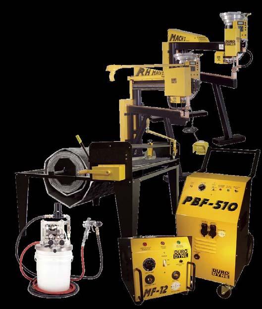


110
 FTC CP CTC Econo Point FTC weld pins utilize a specially pointed nail to")
 have dished washers, ribbed nails for faster postweld")


 and NC (nylon) washers are used with PN s.")

, press the insulation onto the pins.")


111 weld type fasteners rib pin (Cp); target pins; SLope pins; econo point (ftc) & (bdep) FTC CP CTC Econo Point FTC weld pins utilize a specially pointed nail to assure uniform welding. Duro Dyne Rib Pins (CP) have dished washers, ribbed nails for faster postweld cooling and precision points to assure uniform quality. BDEP and CTC pins have unique washers designed to improve the quilting contour of the insulation surface. All of the weld pin styles are used with MF, PBF, FG, RH, and FGMH pinspotters. The needle sharp point enables the operator of the machine to easily push the weld pin through the insulation into firm electrical contact with the metal duct. Welding current is supplied by activating the weld transformers. Current flowing through the pin s point of contact creates instantaneous welds of extremely high strength. BDEP All Pins available in 1/2, 3/4, 1, 1-1/8, 1-1/2, 2, & 2-1/8 lengths. LN Spotter pin (pn & Ln) PN NC2/NC1 LC/PC The spotter pin is welded to the sheet metal and the insulation is impaled over the nail. It is held in place with the addition of either metal or nylon washers. PC (metal) and NC (nylon) washers are used with PN s. LC (metal) and NC-2 (nylon) for LN s. Pins can be installed with all DYN-O-LITE, LF, MF and PBF Pinspotters. After the pins are welded to the duct, (1 pin per sq. ft.), press the insulation onto the pins. Pins used should be 1/4 longer than the insulation thickness.push clip over pin to hold insulation firmly in place. PN Pins available in 3/4, 1-1/4, 2, 2-1/2. LN Pins available in 3/4, 1-1/2, 2-1/2, 3-1/2, 4-1/2, 5-1/2. gold SeaL pins SeLf SeaLing pin (SSp) Gold Seal Pins hold the duct liner in place and seal the hole created during insertion. Heat activated gold adhesive on the underside of the washer secures the pin to the liner facing during the welding process. SSP Adhesive coating insulates the underside of the washer to allow welding on foil faced insulation. Gold Seal Pins also feature dished washers and precision formed points to insure consistent penetration of duct liner. Gold Seal Pins are designed for use with all MF, PBF, FG, RH, and FGMH Multihead pinspotters. Gold Seal Pins available in 1/2, 3/4, 1 and 2 lengths. Gold Seal Pins for use with foam insulation are also available.


112 MeCHaniCaL type fasteners LPC DynaStiCK SeLf adhesive insulation Hanger NC1 SAH Dynastick is an insulation hanger with a self-stick base. Just peel the release paper from the hanger base and firmly press the base to the clean duct surface. Impale the insulation over the hanger nail and slip on the locking washer. Self-stick hangers adhere to clean metal surfaces and withstand temperatures of up to 175 F. SAH Available in 3/4, 1-1/4, 1-3/4, 2, 2-1/2 & 3-1/2 lengths. PEEL OFF PROTECTIVE PAPER PRESS PIN FIRMLY TO SURFACE PRESS DOWN WASHER OVER PIN LPC DynaStiCK insulation Hanger NC1 PBH Dynastick is a perforated base hanger for use with super strength PBA mastic. Simply place a small amount of PBA on a perforated base and firmly press the hanger against the duct surface. Allow the PBA mastic to dry, then, impale the insulation over the hanger nail and slip on a locking washer. Duro Dyne PBA adheres to concrete, metal or wood surfaces and withstands constant temperatures up to 180 F. PBH Available in 3/4, 1-1/4, 1-3/4, 2, & 2-1/2 lengths. APPLY ADHESIVE WITH FLAT EDGE OR APPLY ADHESIVE WITH CAULKING GUN PRESS PIN FIRMLY TO SURFACE flipsti FSG PATENT #5,325,964 SELF ADHESIVE INSULATION HANGER WITH THE UNIQUE ONE PIECE DESIGN A unique insulation hanger with a self stick base. One fastener can be used for insulation up to 2 thick. Optional extension allows for use on up to 6 thick insulation or wrap. It is the only fastener available in galvanized, aluminum and stainless steel. Insulation can be secured simply by bending the tip of the extended pin or using supplied washers. Flipstix can be used on any clean metal or painted surface and will withstand temperatures of up to 175 F.


113 MeCHaniCaL type fasteners StiK-taC SELF-ADHESIVE INSULATION FASTENER Available in 1-3/4 & 2-1/2 lengths. Stik-Tac Insulation fasteners are an economical solution to self-stick insulation needs. Stik-Tacs have a 1-3/8 inch square base and high strength foam tape for superior holding power. Just peel off the protective backing and firmly press the base on to the cleaned duct surface. To complete the installation impale the insulation on the nail and secure with an LPC steel or NC1 nylon washer. Withstand temperatures up to 175 degrees F. TBG BG banger IMPACT DRIVEN FASTENERS Easy to install - place the liner over the sheet metal and drive the banger through the insulation. Upon impact, the jaws (three on the Tripod for added stability, two on the standard Banger), of the fastener penetrate the metal and lock securely within the thickness of the metal itself. (Always place a hardened steel block behind the sheet metal at the point of impact). Bangers can be installed with model DHH Double Headed Hammer or AB-5 Automatic Banger Setter. BG IS AVAILABLE IN 1/2 & 1 TBG IS AVAILABLE IN 1/2 & 1, 1-1/8,& 1-1/2 adhesive applicators SUper SprayfaSt ADHESIVE APPLICATOR FOR USE WITH WIT & WSA ADHESIVES 5 GALLON SySTEM ITEM # GALLON SySTEM ITEM #5155 The Super Sprayfast is an air powered adhesive spray system designed for use with 5 gallon or 55 gallon containers of Duro Dyne water based adhesives.the Super Sprayfast incorporates an Acetal / Teflon diaphragm pump, circulating system and surge tank. It requires PSI gbac L TO R SHOWN ADHESIVE APPLICATOR FOR USE WITH WSA & WIT ADHESIVES L TO R FLOW ITEM #39171 R TO L FLOW ITEM #39250 The GBAC applies Duro Dyne WIT or WSA water base adhesive to insulation in preparation for application to sheet metal. It requires 110v service fused for 15 amps. A source of air is required. Specify the direction of work flow when ordering. wit INSULATION ADHESIVE - ITEM #5056 Water-based Insulation Adhesive specifically designed for Spray, Roller and Brush application. WIT is white in color when applied but dries clear for a clean look. WIT features good wet tack, is non-flammable both in the wet and dry state and is classified by UL (file#r5286). Available in 1 gallon pails, 5 gallon pails and 55 gallon drums.


114 insulation CUtterS LSU LINER SIzER FOR USE WITH 1/2 TO 2 LINER ITEM# Duro Dyne s LSU Advanced Liner Sizer is an enhanced version of the popular Model LS5 making it capable of cutting cotton fiber insulations, filter media and rubberized products as well as fiberglass duct liner. The cross cut and slitter blades are mechanically gear driven to spin while cutting. This spinning action enables the LSU to create precise cuts in the most difficult materials. LS-5 LINER SIzER FOR USE WITH 1/2 TO 2 LINER ITEM# The LS5 is a manual insulation cutter that slits fiberglass insulation to length and width. The operator feeds the insulation with a crank handle to the desired length. An adjustable slitter blade automatically cuts to desired width. The operator then pulls the crosscut blade across the machine and removes the sized insulation. pls AUTOMATIC INSULATION CUTTER FOR USE WITH 1/2 TO 2 LINER L TO R FLOW - ITEM#39075 R TO L FLOW - ITEM#39251 L TO R SHOWN The PLS is used for production line cutting of fiberglass insulation. An electric eye controls the fully automatic run-out and the cutting of the insulation. It requires 110v power service fused for 15 amps. A source of air is required. Specify the direction of work flow when ordering.
 that welds 14 gauge PN style pins to ductwork up to 22 gauge. Insert a PN Pin into the magnetic tip and depress the trigger.")


115 installation MaCHineS Lf 1000/2000 Ln HAND HELD PINSPOTTER 110 VOLT - ITEM# VOLT - ITEM# The LF is a portable unit (9 lbs.) that welds 14 gauge PN style pins to ductwork up to 22 gauge. Insert a PN Pin into the magnetic tip and depress the trigger. A timed burst of electricity fuses the pin to the steel. It can also weld LN style pins up to 5-1/2 long with the use of a TPL2 tip purchased separately. Available in 110v & 220v, 50 to 60hz; fuse for 15 amps. Mf-12 COMPACT PINSPOTTER FOR USE WITH 1/2, 3/4 & 1 WELD PINS ITEM #27115 The MF-12 welds BDEP, CTC, SSP, CP, FTC, PN or LN type fasteners to ductwork up to 20 gauge. It requires 220 volt, 50 to 60 hz service fused for 30 amps. Place a pin on the magnetic tip. Insert the pin through the insulation, give the pin a 1/4 twist, and depress the trigger switch. For LN type fasteners use a TPL2 tip. For PN type fasteners use a TP2 tip. pbf-510 HEAVy DUTy PINSPOTTER FOR USE WITH 1/2 TO 2 WELD PINS ITEM#27372 The PBF-510 welds BDEP, CTC, SSP, CP, FTC, PN or LN type fasteners to ductwork up to 18 gauge. It requires 220 volt, 50 to 60 hz service fused for 100 amps. Place a pin on the magnetic tip, insert the pin through the insulation, give the pin a 1/4 twist and depress the trigger switch. For LN type fasteners use a TPL2 tip. For PN type fasteners use a TP2 tip.


116 installation MaCHineS fg MaCH i & ii MACH I & MACH II AUTOMATIC BULK FEED PINSPOTTER WITH FIVE FOOT THROAT ITEM #18001 & #18002 The FG MACH I & II welds BDEP, CTC, SSP, CP & FTC type fasteners. The FG MACH I can weld to ductwork up to 20 gauge. It requires 220v, 50 to 60hz; service fused for 30 amps. The FG MACH II can weld to ductwork up to 18 gauge. It requires 220v, 50 to 60hz service, fused for 100 amps. A source of 85 psi air is required for both. Footswitch actuated, fasteners are inserted through the insulation and welded in place. rh MaCH ii ROLLING HEAD AUTOMATIC PINSPOTTER ITEM #18010 RH MACH II welds BDEP, CTC, SSP, CP & FTC type fasteners to ductwork up to 18 gauge. It requires 220v, 50 to 60hz service, fused for 100 amps. A source of 85 psi air is required. Position a fastener over the insulation and depress the trigger switch. The machine inserts the fastener through the insulation and welds it to the steel. ab-5 AUTOMATIC BANGER SETTER FOR USE WITH 1/2 TO 1-1/2 TRIPOD OR STANDARD BANGERS ITEM #17297 An AB-5 installs Banger Type Fasteners (Tripod & Standard) in ductwork 26 to 18 gauge. It requires 110 Volt, 50 to 60 hz service fused for 15 amps. A source of 85 psi air is required.the footswitch is depressed, and the machine inserts a fastener through the insulation and into the steel.


117 Duro Dyne Insulation Fasteners are manufactured in the U.S.A. For the most updated product information, please visit our website Duro Dyne Corp. Printed in USA 2/10 BB Duro Dyne East Division, Bay Shore, Ny Fax: Duro Dyne Midwest Division, Fairfield, OH Fax: Duro Dyne West Division, Santa Fe Springs, CA Fax: Duro Dyne Canada, Lachine, Quebec, Canada Fax:
118 JOB: LOCATION: SUBMITTED TO: SUBMITTAL PREPARED BY: APPROVED BY: DATE: An Employee Owned Company 97 Dexter Road, East Providence, Rhode Island SUBMITTAL FORM INSULATION FASTENERS Tel: (800) Fax: (401) ISO 9001 : 2008 Basic Use PowerPoint Weld Pins and Gripnail Insulation fasteners are used to permanently secure insulation to the inside of sheet metal ductwork. SnapStik are used to secure insulation to the inside or outside of sheet metal ductwork. Product Guarantee All PowerPoint Weld Pins, Gripnail Insulation Fasteners, and SnapStik Insulation Fasteners are guaranteed against defective material. Industry Regulations PowerPoint Weld Pins and Gripnail Insulations fasteners meet the guidelines for low and high velocity ductwork as outlined by the SMACNA standards, HVAC DUCT CONSTRUCTION STANDARDS 1995 Edition. Suggested Specifications All duct liner shall be secured to the ductwork in accordance with SMACNA HVAC Duct Construction Standards. Fasteners shall be: Type Fasteners Part # s (adhesive, mechanical, weld) As manufactured by Gripnail Corporation, East Providence, R.I. Impact Applied Duct Liner Fasteners Description Gripnails are a proven mechanical fastener used to attach insulation to the inside of sheet metal ductwork. The hardened tapered teeth pierce the duct liner and then clench into the sheet metal ductwork to form a permanent attachment. Resistance Weld Duct Liner Fastener Description PowerPoint weld pins are proven welded fasteners used to attach insulation to the inside of sheet metal ductwork. This forms a permanent bond between the fastener and sheet metal as they become the same as in any ordinary weld. Pressure Sensitive Adhesive Duct Liner Fastener Description Gripnail SnapStik Insulation Hangers are pressure sensitive fasteners designed to secure inside or outside of sheet metal ductwork Adhesive Affixed Duct Liner Fastener Description Gripnail SnapStik Spindle Anchors are adhesive affixed fasteners, designed to secure inside or outside of sheet metal ductwork
119 Impact Applied Duct Liner Fasteners Gripnail Pin Diameter: 10 gauge Washer Diameter: 1.0 Pin Diameter: 10 gauge Washer Diameter: 1.0 Meets or exceeds SMACNA Standards for Duct Liner Fasteners Feeds automatically into application equipment Beveled Edge Cap prevents tearing of liner Made in U.S.A. Resistance Weld Duct Liner Fasteners PowerPoint Weld Pin Meets or exceeds SMACNA Standards for Duct Liner Fasteners Faster Welds forged diamond point design creates more electrical resistance for faster welds Super Sharp Point 22 degree point is the sharpest in the industry and cleanly pierces the toughest duct liner Beveled Edge Cap prevents tearing of duct liner Made in U.S.A. Product Installed Length Recommended For # /2 insulation All densities # insulation 1 1/2 lbs. density # insulation 3 lbs. density # insulation 4 & 6 lbs. density # /2 insulation 1 1/2 lbs. density # insulation 1 1/2 & 2 lbs. density Product Installed Length Recommended For # /2 insulation All densities # insulation 1 1/2 lbs. density # insulation All densities # insulation 3 lbs. density # /2 insulation All densities # insulation 1 1/2 & 2 lbs. density # insulation 3 lbs. Pressure Sensitive and Adhesive Affixed Duct Liner Fasteners SnapStik Insulation Hanger Pin Diameter: 12 gauge Washers Part # 825 Washer Size 1 1/4 1 1/8 Fasteners and self-locking washers are manufactured from low carbon galvanized steel The SnapStik Pull-and-Peel system allows for quicker installation Manufactured in single rows of 5 hangers provides safer and more efficient handling SnapStik Spindle Anchor Part Number Spindle Length 820 3/ / / /2 Pin Diameter: 12 gauge Washers Part # 825 Washer Size 1 1/4 1 1/8 Fasteners and self-locking washers are manufactured from low carbon galvanized steel Manufactured in single rows of 5 hangers provides safer and more efficient handling Part Number Spindle Length / / /2
120 Mineral Wool Insulations

121 MINERAL WOOL INSULATIONS INDUSTRIAL MinWool-1200 Pipe HIGH TEMPERATURE INSULATION DESCRIPTION IIG MinWool-1200 Pipe Insulation is made of inorganic fibers derived from basalt, a volcanic rock, with a thermosetting resin binder. Advanced manufacturing technology ensures consistent product quality, with high fiber density and low shot content, for excellent performance in high temperature thermal control and fire resistance applications. ADVANTAGES Thermal Performance. Good thermal conductivity values help minimize and control heat loss, contributing to reduced operating costs and greater energy savings. High dimensional stability and low shrinkage reduce the potential for gaps forming at joints. Lightweight, Low Dust. Easy to handle and fabricate, MinWool-1200 is easy to cut with a knife. Clean handling properties help reduce irritation and minimize job clean-up time and expense. Low Smoke & Flame Spread. MinWool-1200 has a flame spread rating of 5 and a smoke developed rating of 0 when tested in accordance with ASTM E84, UL 723, CAN/ULC-S102-M. Noncombustible. MinWool-1200 is rated as non-combustible in accordance with ASTM E136 and CAN4-S114-M. Mold Resistant. IIG MinWool-1200 does not support growth of fungi. APPLICATIONS MinWool-1200 Pipe Insulation provides excellent thermal insulation performance for mechanical/power and process piping systems operating from sub-ambient to 1200 F(650 C). This molded pipe insulation is easily fabricated, cutting cleanly and easily with a knife. Very low in-service shrinkage helps prevent gaps from forming at joints, preventing costly thermal leaks. The insulation is designed to be field-jacketed. It may be installed directly on hot surfaces; system shutdown and staged heat-up are not required. AVAILABLE THICKNESSES Standard Thicknesses in ½ Increments (25, 38, 51, 64, 76, 89, 102,114, 127, 140, 152mm) For pipe sizes 19 to 24 (457 mm to 600 mm), some thick wall pieces are shipped as four piece quads. MinWool-1200 pipe insulation is 36 (914 mm) in length, and is available in thicknesses from 1 to 6 (25 mm to 150 mm) in ½ (15 mm) increments. Thick wall material is furnished in double layers. Pipe Sizes (in.) (mm) Form ½ One Piece Two Piece Four Piece Your insulation partner in a safer work place and world. MinWool-1200 Pipe Operating Temperature Limit: 1200 F (650 C) SPECIFICATION COMPLIANCE ASTM C447 Maximum Service Temperature 1200 F (650 C) ASTM C547 Material Specification Types I, II, IV ASTM C585 Dimensional Pipe insulation Complies ASTM C665 Corrosivity to Steel Passes ASTM C795/C871/C692 Passes <1% by Weight, <.02% by Volume ASTM C1104 Water Vapor 120 F(50 C), 95% RH ASTM C1338 Fungi Resistant Passes ASTM E84 Flame Spread/Smoke Developed 5/0 ASTM E136 Noncombustible Passes CAN/CGSB-51.9 Class 3 NRC Reg. Guide 1.36 Passes Recovery after 10% Compression 100% Shot Content <25% LINEAR SHRINKAGE AFTER 24 HRS. AT TEMPERATURE Temperature Shrinkage F C (%) <2 SAFETY Personnel Process Planet IIG-401 Effective (Replaces )
122 MinWool-1200 Pipe HIGH TEMPERATURE INSULATION THERMAL CONDUCTIVITY * PRODUCT CERTIFICATION When ordering material to comply with any government specification or any other listed specification, a statement of that fact must appear on the purchase order. Government regulations and other listed specifications require specific lot testing, and prohibit the certification of compliance after shipment has been made. There may be additional charges associated with specification compliance testing. Please refer to IIG-CSP-3 for Certification Procedures and Charges. Call customer service for more information. QUALITY STATEMENT IIG Products are designed, manufactured and tested to strict quality standards in our own facilities. This along with third party auditing is your assurance that this product delivers consistent high quality. THERMAL CONDUCTIVITY Mean Temperature Thermal Conductivity ºF ºC Btu in/(hr ft 2 ºF) W/m ºC * MinWool Pipe Insulation as tested in accordance with ASTM C335. ADDITIONAL INFORMATION AND MSDS Please visit our website at Industrial Insulation Group, LLC is a Johns Manville company. IIG manufactures MinWool-1200 mineral fiber pipe, block and a variety of other insulations; Thermo-12 Gold Calcium Silicate pipe and block insulation; Super Firetemp fireproofing board; SprouleWR-1200 Perlite pipe and block insulation; high temperature adhesives, and insulating finishing cement LINE STREET BRUNSWICK, GA Industrial Insulation Group. Printed in USA. The physical and chemical properties presented herein represent typical, average values obtained in accordance with accepted test methods and are subject to normal manufacturing variations. They are supplied as a technical service and are subject to change without notice. Numerical flame spread and smoke developed ratings are not intended to reflect hazards presented by these or any other materials under actual fire conditions. Check with the Customer Service Office to assure current information. All Industrial Insulation Group products are sold subject to the IIG Limited Warranty and Limitation of Remedy. For a copy of the IIG Limited Warranty and Limitation of Remedy, - info@iig-llc.com. CUSTOMER SERVICE, TECHNICAL & GENERAL INFORMATION (800) IIG-401 Effective (Replaces )


123 ICA M.W HI-TEMP PIPE INSULATORS ICA M.W Dual-Temperature, Premolded, Top Quality, Two-Pieced Thermal- Acoustical Pipe Fitting Insulators TECHNICAL DATA The ICA M.W is a unique product in the realm of hightemperature preformed insulation for pipe fitting areas. Long-radius weld-l half section highlighting smooth interior and exterior contours and close tolerance to pipe arc. View of fitting demonstrating the precise match of the two-piece unit. Short-radius screwed fitting schedule 80 in ICA M.W and conformance to aluminum cover. The ICA M.W pipe fitting insulator is serviceable to 1200 F and was designed to be utilized in conjunction with any high temperature straight-run insulation of equal surface temperature capabilities. ICA M.W pipe fitting insulators have been employed successfully in mineral wool, calcium silicate, and expanded perlite systems. ICA s molding process yields a fitting insulator which is completely different from the routed fitting insulators which have been extensively marketed in the past. In a routed nsulator the finished product is cut from a section of block insulation with comprising fibers being oriented in a single direction, hence, extreme fragility in the finished product. In contrast, the ICA product is molded under extreme heat and pressure from uncured green felt which is impregnated with a thermo-setting resin. Thus the ICA M.W fitting insulator is composed of fibers that are interbonded and intermeshed in many different directions; the resulting strength means that the ICA insulation cover can be and is produced in fitting sizes never before realized. Unlike a routed insulator, the ICA fitting insulator will not readily delaminate. When coating of the fitting s exterior surface is desired or required, fibers will not dust or fuzz up. This remarkably durable insulator exhibits superior loadbearing characteristics when compared to previous applications, for fitting areas. Extensive on-the-job loss due to breakage is a thing of the past. The ICA M.W is actually strong enough to be utilized on line, removed for inspection or maintenance purposes. and utilized once again. ICA M.W pipe fitting insulator are molded in two half sections, matching the density and thickness standards of the adjoining pipe covering. All fitting insulators are currently manufactured in weld, screwed, socket, and copper tubing types; all in 90 and 45 and tee configurations. For pipe sized presently unavailable and for further speciality application requirements, consult with ICA s Research and Development Department regarding our design and engineering capabilities.
124 ICA M.W APPLICATIONS: Since the ICA M.W is not a mitered or segmented unit, there are no cracks or voids to fill on the exterior surface. The fitting insulators are simply and quickly applied by placing two premolded matching half sections over the pipe fitting and joining them together using tape, wire or adhesive. BENEFITS OF USING PRE-FORMED ICA M.W FITTING COVERS: Two-piece, pre-formed design minimizes guess work in estimates of labor and fitting costs. Insulation can be applied prior to pressure of the mechanical systems, thus saving weeks of delay in application time. Where necessary, fitting insulators can be removed, the testing completed, and the same covered wired back on the system intact. Superior tensil strength and load bearing qualities. Excellent K factor. Mineral wool has always been a known performer in regards to thermal efficiency. ASBESTOS FREE AVAILABILITY CHART Pipe Fitting Covers Available For... Type Pipe Size Insulation Thickness Screwed & Socket 90 & 45 Elbows Screwed & Weld Tees* Long Radius Weld 90 & 45 Elbows 1/2 through 4 1/2 through 6 1/2 through 24 *Larger T s up to 12 available in the near future / / / / / / / / / / / /2 Easy to handle and install in the field - resulting in fast, economical application. Eliminates costly blanket wrapping or mitering. Composite system provides a natural expansion joint. Allows damage free expansion/contraction/deflection in fittings and covering. All interior surfaces are stamped with the ICA H and the proper pipe and thickness size for quick field indentification. PHYSICAL PROPERTIES: Service Temperature Limit, F ASTM E84 Flame Spread/Smoke Development...5/0 ASTM E136/CAN4-S114-M...Noncombustible Thermal Conductivity BTU in/(hr Ft 2 F) THERMAL CONDUCTIVITY ( k ) ( F) ( C) ASTM C Complies Density, Lbs./Cu. Ft. (Nominal) Moisture Absorption... Non-hydroscopic Linear Shrinkage, % (@1200 F)...Less than 2% ph...approximately neutral Mold Resistence...Does not support mold growth Mean F Temperature C Btu in/(hr ft 2 F) W/m C Thermal conductivity and physical properties based on unfaced mineral wool fittings. Technical data as supplied by Eagle-Pitcher. SPECIFICATION COMPLIANCE: ASTM Specifications MIL Specifications ASTM E84 MIL B ASTM C585 MIL B* NRC Specifications Federal Specifications NRC 1.36* HH-I-558B, Type III, Form E, Class 17 *Please contact ICA Headquarters before order placement, refernce compliance to NRC reg. guide 1.36 and MIL-24244B for special handling. *NOTE* Consult ICA regarding further specification information.

125 MINERAL WOOL INSULATIONS INDUSTRIAL MinWool-1200 Industrial Board HIGH TEMPERATURE INSULATION DESCRIPTION IIG MinWool-1200 Industrial Board Insulation is made of inorganic fibers derived from basalt, a volcanic rock, with a thermosetting resin binder. Advanced manufacturing technology ensures consistent product quality, with high fiber density and low shot content, for excellent performance in high temperature thermal control and fire resistance applications. ADVANTAGES Thermal Performance. Good thermal conductivity values help maximize control of heat loss, contributing to reduced operating costs and greater energy savings. Lightweight, Low Dust. Easy to handle and fabricate, these boards are easy to cut with a knife. Clean handling properties help reduce irritation and minimize job clean-up time and expense. Low Smoke & Flame Spread. When tested in accordance with ASTM E84, UL 723, CAN/ULC-S102-M, these unfaced insulation boards have a flame spread rating of 5 and a smoke developed rating of 0. The faced insulation has a flame spread rating of 25 and a smoke developed rating of 5. Noncombustible. MinWool-1200 Industrial Board is rated as noncombustible in accordance with ASTM E136 and CAN4-S114-M. Mold Resistant. IIG MinWool-1200 does not support growth of fungi. APPLICATIONS MinWool-1200 Industrial Board Insulation provides excellent thermal insulation performance for mechanical, power and process systems operating from sub-ambient to 1200 F(650 C). These industrial board insulations are easily fabricated, cutting cleanly and easily with a knife. Very low in-service shrinkage helps prevent gaps from forming at joints, preventing costly thermal leaks. The insulation is designed to be fieldjacketed. It may be installed directly on hot surfaces; system shut-down and staged heat-up are not required. AVAILABLE TYPES IIG MinWool-1200 Industrial Boards are available in six nominal densities in accordance with ASTM C612 and in a range of standard thicknesses, as follows: Type Nominal Density Ib/ft kg/m Standard Sizes: 24 x 48 (610mm x 1219mm) 36 x 48 (914mm x 1219mm) Standard Thicknesses: 1 to 4 (25 mm to 102 mm). 1½ to 4 (38 mm to 102 mm) industrial boards are available with FSP (Foil Scrim Polyethylene) facings on a made-to-order basis. Minimum order quantities will apply. Other thicknesses may be available upon request. MinWool-1200 Industrial Board Operating Temperature Limit: 1200 F (650 C) 1A-4A ASTM C612 TYPES All Boards 4B 1280, 1210, 1212 SPECIFICATION COMPLIANCE ASTM C612 Material Specification Complies ASTM C356 In-Service Shrinkage 0% at 1050 F (566 C); <2% at 1200 F (650 C) ASTM C447 Maximum Service Temperature 1200 F(650 C) ASTM C665 Corrosivity to Steel Passes ASTM C795/C871/C692 Stainless Steel Passes <1% by Weight, <.02% by Volume ASTM C1104 Water Vapor 120 F(50 C), 95% RH ASTM C1335 Shot Content <25% ASTM C1338 Fungi Resistant Passes ASTM E84 Flame Spread/Smoke Developed ASTM E136 Noncombustible UL 723, CAN/ULC-S102-M Unfaced 5/0 or less Faced 25/5 or less Passes IB 1230 IB 1240 IB 1260-IB 1212 ADDITIONAL INFORMATION AND MSDS Please visit our website at Unfaced 5/0 or less Faced 25/5 or less 75 F 4.0 per inch of thickness 4.2 per inch of thickness 4.3 per inch of thickness Your insulation partner in a safer work place and world. SAFETY Personnel Process Planet IIG (REPLACES 02-12)
 Apparent Thermal Conductivity Btu in/(hr ft 2 F) 1230 1240 1260 1280 1210 1212 THERMAL PERFORMANCE (SI UNITS) * Mean Temp.")
126 MinWool-1200 Industrial Board HIGH TEMPERATURE INSULATION THERMAL PERFORMANCE (IP UNITS) * Mean Temp. ( F) Apparent Thermal Conductivity Btu in/(hr ft 2 F) THERMAL PERFORMANCE (SI UNITS) * Mean Temp. ( C) Apparent Thermal Conductivity W/m C * MinWool Industrial Board Insulation as tested in accordance with ASTM C177 and ASTM C518. THERMAL CONDUCTIVITY ACOUSTICAL PERFORMANCE Sound Absorption Coefficients Thickness 1/3 Octave Band Center Frequencies, Hz Type (in) (mm) NRC ½ ½ ½ PRODUCT CERTIFICATION When ordering material to comply with any government specification or any other listed specification, a statement of that fact must appear on the purchase order. Government regulations and other listed specifications require specific lot testing, and prohibit the certification of compliance after shipment has been made. There may be additional charges associated with specification compliance testing. Please refer to IIG-CSP-3 for Certification Procedures and Charges. Call customer service for more information. Industrial Insulation Group, LLC is a Johns Manville company. IIG manufactures MinWool-1200 mineral fiber pipe, block and a variety of other insulations; Thermo-12 Gold Calcium Silicate pipe and block insulation; Super Firetemp fireproofing board; SprouleWR-1200 Perlite pipe and block insulation; high temperature adhesives, and insulating finishing cement LINE STREET BRUNSWICK, GA Industrial Insulation Group. Printed in USA. QUALITY STATEMENT IIG Products are designed, manufactured and tested to strict quality standards in our own facilities. This along with third party auditing is your assurance that this product delivers consistent high quality. The physical and chemical properties presented herein represent typical, average values obtained in accordance with accepted test methods and are subject to normal manufacturing variations. They are supplied as a technical service and are subject to change without notice. Numerical flame spread and smoke developed ratings are not intended to reflect hazards presented by these or any other materials under actual fire conditions. Check with the Customer Service Office to assure current information. All Industrial Insulation Group products are sold subject to the IIG Limited Warranty and Limitation of Remedy. For a copy of the IIG Limited Warranty and Limitation of Remedy, - info@iig-llc.com. CUSTOMER SERVICE, TECHNICAL & GENERAL INFORMATION (800) IIG (REPLACES 02-12)

127 MinWool-1200 Pipe and Tank Wrap FSP FACED HIGH TEMPERATURE INSULATION DESCRIPTION MinWool-1200 Pipe and Tank Wrap Insulation is made of inorganic fibers derived from basalt, a volcanic rock, with a thermosetting resin binder. Advanced manufacturing technology ensures consistent product quality, with high fiber density and low shot content, for excellent performance in high temperature, thermal control and fireresistant applications. ADVANTAGES Thermal Performance. Good thermal conductivity values help maximize control of heat loss, contributing to reduced operating costs and greater energy savings. High dimensional stability and low shrinkage reduce the potential for gaps forming at joints. Lightweight, Low Dust. Easy to handle and fabricate, these blankets cut cleanly with a knife. Clean handling properties help reduce irritation and minimize job clean-up time and expense. Low Smoke & Flame Spread. When tested in accordance with ASTM E84, UL 723, CAN/ULC-S102-M, MinWool-1200 Pipe and Tank Wrap blankets have a flame spread rating of 25 and a smoke developed rating of 5. Mold Resistant. IIG MinWool-1200 does not support growth of fungi. APPLICATIONS MinWool-1200 Pipe and Tank Wrap Insulation provides excellent thermal insulation performance for mechanical equipment, structural members, vessels, furnaces, large diameter piping, and any other irregularly shaped systems operating from sub-ambient to 1200 F(650 C). Pipe and Tank Wrap Insulation is easily fabricated, cutting cleanly with a knife. Very low in-service shrinkage helps prevent gaps from forming at joints, preventing costly thermal leaks. It may be installed directly on hot surfaces; system shut-down and staged heatup are not required. A sufficient thickness of insulation must be used to keep the maximum facing temperature of Pipe and Tank Wrap below 150 F. Insulation thickness must be reviewed for each application. It is not recommended for use as an inside layer in nested applications. AVAILABILITY MinWool-1200 Pipe and Tank Wrap is FSP (Foil Scrim Polyethylene) faced and has a nominal density of 8 pcf (128 kgs/m 3 ). Thickness Width Roll Length in. mm in. meters ft. meters 1½ ½ ½ Your insulation partner in a safer work place and world. MINERAL WOOL INSULATIONS INDUSTRIAL MinWool-1200 Pipe and Tank Wrap Operating Temperature Limit: 1200 F (650 C) ASTM C356 In-Service Shrinkage ASTM C447 Max Service Temperature ASTM C553 Mineral Fiber Blanket Specification SPECIFICATION COMPLIANCE ASTM C665 Corrosivity to Steel ASTM C795/C871/C692 0% at 1050 F (566 C); <2% at 1200 F (650 C) 1200 F (650 C) Types l, ll, lll, lv, V, VI Passes Passes ASTM C1104 Water Vapor Sorption <1% by Weight, <.02% by 120 F(50 C), 95% RH ASTM C1335 Shot Content <25% ASTM C1338 Fungi Resistance Passes ASTM E84 Flame Spread/Smoke Developed 25/5 UL 723, CAN/ULC-S102-M 25/5 75 F 4.3 per inch of thickness ADDITIONAL INFORMATION AND MSDS Please visit our website at SAFETY Personnel Process Planet IIG (REPLACES 07-10)
128 MinWool-1200 Pipe and Tank Wrap FSP FACED HIGH TEMPERATURE INSULATION PRODUCT CERTIFICATION When ordering material to comply with any government specification or any other listed specification, a statement of that fact must appear on the purchase order. Government regulations and other listed specifications require specific lot testing, and prohibit the certification of compliance after shipment has been made. There may be additional charges associated with specification compliance testing. Please refer to IIG-CSP-3 for Certification Procedures and Charges. Call customer service for more information. QUALITY STATEMENT IIG Products are designed, manufactured and tested to strict quality standards in our own facilities. This along with third party auditing is your assurance that this product delivers consistent high quality. THERMAL CONDUCTIVITY Mean Temperature Thermal Conductivity ºF ºC Btu in/(hr ft 2 ºF) W/m ºC Industrial Insulation Group, LLC is a Johns Manville company. IIG manufactures MinWool-1200 mineral fiber pipe, block and a variety of other insulations; Thermo-12 Gold Calcium Silicate pipe and block insulation; Super Firetemp fireproofing board; SprouleWR-1200 Perlite pipe and block insulation; high temperature adhesives, and insulating finishing cement LINE STREET BRUNSWICK, GA Industrial Insulation Group. Printed in USA. The physical and chemical properties presented herein represent typical, average values obtained in accordance with accepted test methods and are subject to normal manufacturing variations. They are supplied as a technical service and are subject to change without notice. Numerical flame spread and smoke developed ratings are not intended to reflect hazards presented by these or any other materials under actual fire conditions. Check with the Customer Service Office to assure current information. All Industrial Insulation Group products are sold subject to the IIG Limited Warranty and Limitation of Remedy. For a copy of the IIG Limited Warranty and Limitation of Remedy, - info@iig-llc.com. CUSTOMER SERVICE, TECHNICAL & GENERAL INFORMATION (800) IIG (REPLACES 07-10)
129 PVC Fitting Covers

130
131
132 PyroGel Insulation

 0.")
133 COLD to HOT We ve Got You Covered DATA SHEET Pyrogel T FLEIBLE INDUSTRIAL INSULATION FOR HIGH-TEMPERATURE APPLICATIONS Pyrogel T is a high-temperature insulation blanket formed of silica aerogel and reinforced with a non-woven, glass-fiber batting. Silica aerogels possess the lowest thermal conductivity of any known solid. Pyrogel T achieves this industry-leading thermal performance in a flexible, environmentally safe, and easy-to-use product. Ideal for insulating piping, vessels, tanks, and equipment, Pyrogel T is an essential material for those seeking the ultimate in thermal efficiency. Physical Properties Thicknesses * 0.20 in (5 mm) 0.40 in (10 mm) Material Form * Max. Use Temp. Color Density * Hydrophobic 60 in (1,500 mm) wide x 260 ft (80 m) long rolls 1200 F (650 C) Beige 11 lb/ft 3 (0.18 g/cc) Yes 60 in (1,500 mm) wide x 155 ft (47 m) long rolls * Nominal Values Advantages Superior Thermal Performance Up to five times better thermal performance than competing insulation products Reduced Thickness and Profile Equal thermal resistance at a fraction of the thickness Less Time and Labor to Install Easily cut and conformed to complex shapes, tight curvatures, and spaces with restricted access Physically Robust Soft and flexible but with excellent springback, Pyrogel T recovers its thermal performance even after compression events as high as 100 psi Shipping and Warehousing Savings Reduced material volume, high packing density, and low scrap rates can reduce logistics costs by a factor of five or more compared to rigid, pre-formed insulations Simplified Inventory Unlike rigid pre-forms such as pipe cover or board, the same Pyrogel T blanket can be kitted to fit any shape or design Thermal Conductivity ASTM C 177 Results Thermal Conductivity, k (BTU-in/hr-ft 2 - F) Temperature ( F) Temperature ( C) Thermal Conductivity, k (mw/m-k) Hydrophobic Yet Breathable Pyrogel T repels liquid water but allows vapor to pass through, helping to prevent corrosion under insulation Environmentally Safe Landfill disposable, shot-free, with no respirable fiber content Mean Temp. C F k mw/m-k BTU-in/hr-ft 2 - F Thermal conductivity measurements taken at a compressive load of 2 psi.
134 COLD to HOT We ve Got You Covered Pyrogel T Thicknesses Required for Personnel Protection * Design conditions: Ambient temperature = 86 F (30 C) Wind speed = 2.2 mph (1 m/s) Surface emissivity = 0.15 Max. touch temp = 140 F (60 C) *These data are provided as an example only. Actual performance should be determined using the parameters relevant to the particular application. Please contact Aspen Aerogels for technical assistance. NPS in (mm) 100 C (210 F) Pyrogel T Thickness (mm) vs. Process Temperature and Nominal Pipe Size 150 C (300 F) 200 C (390 F) 250 C (480 F) 300 C (570 F) 350 C (660 F) 400 C (750 F) 450 C (840 F) 500 C (930 F) 550 C (1020 F) 600 C (1110 F) 0.5 (15) (20) (25) (40) (50) (80) (100) (150) (200) (250) (300) (350) (400) (450) (500) (600) (700) (750) (900) (1200) Flat C (1200 F) 5 mm product 5 mm and/or 10 mm product Specification Compliance and Performance Test Procedure Property Results ASTM C 1728, Type III, Grade 1A Standard Specification for Flexible Aerogel Insulation Complies ASTM C 165 Compressive Strength Stress at 10% strain = 14.8 psi (102 kpa) Stress at 25% strain = 26.6 psi (183 kpa) ASTM C 356 Linear Shrinkage Under Soaking Heat < 1200 F (650 C) ASTM C 411 Hot Surface Performance Passed ASTM C 447 Estimation of Maximum Use Temperature 1200 F (650 C) ASTM C (Section 11.11, Modified) Heat and Vibration Aging ASTM C 795 Insulation for Use Over Austenitic Stainless Steel Passed -0.19% mass change after 6 hr vibration Characteristics Pyrogel T can be cut using conventional cutting tools including scissors, tin snips, and razor knives. The material can be dusty, and it is recommended gloves, safety glasses, and dust mask be worn when handling matierial. See MSDS for complete health and safety information. ASTM C 1101 Classifying the Flexibility of Mineral Fiber Blankets Class: Resilient Flexible ASTM C 1104 Water Vapor Sorption 2.25% (by weight) ASTM C 1338 Fungal Resistance of Insulation Materials Passed ASTM C 1511 Liquid Water Retention After Submersion <6% (by weight) ASTM E 84 Surface Burning Characteristics Flame Spread Index = 0 Smoke Developed Index = 0 ASTM E 1354 Cone Calorimetry No ignition at 50 kw/m 2 BS EN : 2007 Reaction to Fire Performance Passed Euroclass A2 ISO 1182:1990 Non-Combustibility Meets criteria outlined in ISO 1182:1990 Information presented herein is typical and representative of material performance. Any and all warranties, either expressed of implied, are disclaimed. All products or materials supplied, including any recommendations or suggestions must be evaluated by the user to determine applicability and suitability for a particular use. Values should not be used directly for specification purposes. Aspen Aerogels, Inc. does not assume any liability for use or misuse of any products produced or supplied. This information replaces all previous information. As a result of the constant development of our products, we reserve the right to make alterations to this information without notice. Aspen Aerogels, Inc. 30 Forbes Road, Building B Northborough, MA USA Phone: Fax: Web: info@aerogel.com Aspen Aerogels and Pyrogel are registered trademarks of Aspen Aerogels, Inc Aspen Aerogels, Inc. REV 7.0


135 COLD to HOT We ve Got You Covered DATA SHEET Cryogel Z FLEIBLE INDUSTRIAL INSULATION WITH INTEGRAL VAPOR BARRIER FOR SUB-AMBIENT AND CRYOGENIC APPLICATIONS Cryogel Z is flexible aerogel blanket insulation with an integral vapor barrier. It is engineered to deliver maximum thermal protection with minimal weight and thickness and zero water vapor permeability. Cryogel Z s unique properties extremely low thermal conductivity, superior flexibility, compression resistance, hydrophobicity, and ease of use make it essential for those seeking the ultimate in thermal protection for cryogenic applications. Using patented nanotechnology, Cryogel Z insulation combines a silica aerogel with reinforcing fibers to deliver industry-leading thermal performance in an easy-to-handle and environmentally safe product. Cryogel Z s extremely low thermal conductivity reduces heat gain and liquid boil-off, its blanket form minimizes installation labor, and its inherent flexibility makes the product durable and resistant to mechanical abuse. Physical Properties Thicknesses * 0.20 in (5 mm) 0.40 in (10 mm) Material Form * Max. Use Temp. Color Density * Hydrophobic Advantages 57 in (1,450 mm) wide x 211 ft (64 m) long rolls 257 F (125 C) White 8.0 lb/ft 3 (0.13 g/cc) Yes Superior Thermal Performance Up to five times better thermal performance than competing insulation products Reduced Thickness and Profile Equal thermal resistance at a fraction of the thickness 57 in (1,450 mm) wide x 126 ft (38 m) long rolls Less Time and Labor to Install Easily cut and conformed to complex shapes, tight curvatures, and spaces with restricted access Zero Permeability Due to Integral Vapor Barrier Provides redundant moisture protection in an easy-to-install package * Nominal Values Physically Robust Soft and flexible but with excellent springback, Cryogel Z recovers its thermal performance even after compression events as high as 850 psi Shipping and Warehousing Savings Reduced material volume, high packing density, and low scrap rates can reduce logistics costs by a factor of five or more compared to rigid, pre-formed insulations Eliminates Contraction Joints Because it remains flexible even at cryogenic temperatures, Cryogel Z eliminates the contraction joints used to prevent compressive failure in other insulation materials Thermal Conductivity ASTM C 177 Results Thermal Conductivity, k (BTU-in/hr-ft 2 - F) Temperature ( F) Temperature ( C) Mean Temp. C F k mw/m-k BTU-in/hr-ft 2 - F Thermal conductivity measurements taken at a compressive load of 2 psi Thermal Conductivity, k (mw/m-k) Environmentally Safe Landfill disposable, shot-free, with no respirable fiber content
136 COLD to HOT We ve Got You Covered Cryogel Z Thicknesses Required to Prevent Surface Condensation * Design conditions: ambient temperature = 80 F (26.7 C), relative humidity = 70%, dew point temperature = 69.3 F (20.7 C), wind speed = 0, surface emissivity = 0.9 Includes 10% safety factor. Cryogel Z Thickness (in) vs. Temperature ( F) NPS (in) / / / inch product inch and/or 0.4 inch product Flat Cryogel Z Thickness (mm) vs. Temperature ( C) NPS (mm) mm product mm and/or 10 mm product Flat *These data are provided as an example only. Actual performance should be determined using the parameters relevant to the particular application. Please contact Aspen Aerogels for technical assistance.
137 COLD to HOT We ve Got You Covered Cryogel Z Thicknesses Required to Prevent Surface Condensation * Design conditions: ambient temperature = 80 F (26.7 C), relative humidity = 80%, dew point temperature = 73.3 F (22.9 C), wind speed = 0, surface emissivity = 0.9 Includes 10% safety factor. Cryogel Z Thickness (in) vs. Temperature ( F) NPS (in) / / / inch product inch and/or 0.4 inch product Flat Cryogel Z Thickness (mm) vs. Temperature ( C) NPS (mm) mm product mm and/or 10 mm product Flat *These data are provided as an example only. Actual performance should be determined using the parameters relevant to the particular application. Please contact Aspen Aerogels for technical assistance.
138 COLD to HOT We ve Got You Covered Cryogel Z Specification Compliance and Performance Test Procedure Property Results ASTM C 1728, Type I, Grade 1B Standard Specification for Flexible Aerogel Insulation Complies ASTM C 165 Compressive Stress Strain %, % ASTM C 871 Standard Specification for Thermal Insulation for Use in Contact With Austenitic Steel PASS ASTM C 1101 Flexibility Flexible ASTM C 1101 Flexibility at Cryogenic Temperature Resilient Flexible ASTM C 1104 Water Vapor Sorption <1.1% (mass) ASTM C 1511 Water Retention after Submersion in Water <4% (mass) ASTM E 84 Flame and Smoke Spread Class A: FSI <5 SDI 20 ASTM E 96 Water Vapor Transmission Rate (with vapor barrier) 0.00 perm ASTM E 228 Linear Coefficient of Thermal Expansion (@ -150 C) x 1.26 x 10⁻⁵ K -1 y 1.34 x 10⁻⁵ K -1 UL 1709 Structural Steel Fire Protection 20 mm 147 min 175 mm 173 min 50 mm 109 min 100 mm min Characteristics Cryogel Z can be cut using conventional cutting tools including scissors, tin snips, razor knives, and hot knives. The material can be dusty, and it is recommended gloves, safety glasses, and dust mask be worn when handling matierial. See MSDS for complete health and safety information. Other Available Materials Aspen Aerogels produces several types of flexible aerogel blanket materials for hot and cold applications. Please contact us for additional information on these products. Information presented herein is typical and representative of material performance. Any and all warranties, either expressed of implied, are disclaimed. All products or materials supplied, including any recommendations or suggestions must be evaluated by the user to determine applicability and suitability for a particular use. Values should not be used directly for specification purposes. Aspen Aerogels, Inc. does not assume any liability for use or misuse of any products produced or supplied. This information replaces all previous information. As a result of the constant development of our products, we reserve the right to make alterations to this information without notice. Aspen Aerogels, Inc. 30 Forbes Road, Building B Northborough, MA USA Phone: Fax: Web: info@aerogel.com Aspen Aerogels and Cryogel are registered trademarks of Aspen Aerogels, Inc Aspen Aerogels, Inc. REV 5.0
139 Stainless Steel Lagging
140 Stainless Steel Roll Jacketing DESCRIPTION ITW's Stainless Steel Roll Jacketing is manufactured from T-304 and T-316 prime grade Stainless Steels. These alloys comply DESCRIPTION with ASTM A-240, and are supplied with a regular dull finish for reduced glare. The yield strength is 30,000-45,000 PSI and the tensile strength is 75, ,000 PSI. These alloys are of a special soft-annealed temper, for ease in fabrication. T-304 is normally used in all except the most corrosive areas, where T-316 is recommended. The 300 series Stainless Steels have a melt point of approximately 2500 F, providing optimum fire protection. Stainless Steel has a higher emittance value than Aluminum, and has physical properties superior to all other metal used as insulation protective jacketing. T-304 contains 18% chromium and 8% nickel. T-316 contains 16.5% chromium, 10% nickel and 2.2% molybdenum. Stainless Steel is available in smooth, stucco embossed, or 3/16" corrugated roll jacketing, and deep corrugated sheets. Jacketing is recommended for insulated piping, tanks, and vessels less than 8 feet in diameter. Deep corrugated sheets are recommended for diameters greater than 8 feet. It is recommended that the roll jacketing be 3/16" corrugated for the following reasons: it is stronger than smooth, it reduces glare from external light sources, it eliminates "coil break" when applied over small size piping and does not show dents readily. In extremely corrosive environments, smooth jacketing is recommended to facilitate run-off. RECOMMENDED USES Chemical Plants and Refineries: Urea units, fertilizer plants, caustic facilities, petrochemical plants and aluminum refineries. Steel Mills: Coke ovens, oxygen steel making furnaces, byproduct plants, aromatic plants and steam distribution facilities. Paper Mills: Digester areas, white and black liquor tanks, bleach tanks, chemical pulping and waste treatment tanks. Miscellaneous: Areas of high incidence of abuse on bridges, walkways and service roads, areas of high fire incidence, food processing facilties, packing plants and freeze facilities. POLYSURLYN MOISTURE RETARDER Polysurlyn consists of a 3 mil thickness of a coextrusion of polyethylene and DuPont's Surlyn which is heat laminated to the metal jacketing. Due to its superior performance characteristics, it replaces the old standard 1 mil and 3 mil polykraft moisture retarders. For cold rooftop and hot work cyclical applications, refer to Technical Information for recommendations. SUGGESTED SPECIFICATION All insulation shall be weatherproofed with ITW's Stainless Steel jacketing. The jacketing is to be manufactured from T-304 (T-316 option) Stainless Steel with 3/16" corrugations (or smooth option) in.010 and.016" thickness (.020 and.024 available). All jacketing shall have an integrally bonded moisture retarder over the surface in contact with the insulation ITW Insulation Systems Pabco/Childers Metals Fax (713) SSRJE-0505 Supercedes SSRJE

141 STAINLESS STEEL ELBOW COVERS Type 316 DESCRIPTION ITW Insulation Systems Stainless Steel Sure-Fit (Pabco) or Ell-Jacs (Childers) Insulation Fitting Covers are made in two precision formed matching halves and are sized to cover and weatherproof insulated 90 and 45 elbows along pipelines. They are manufactured from Type-316 Stainless Steel in.016" thickness. They can be used on long and short radius, butt weld, socket weld, and screwed pipe elbows from 1/2" to 10" Iron Pipe Size, inclusive. Type 316 alloy has a melting point of approximately 2500 and consists of 16% chromium, 10% nickel, and 2% molybdenum. ADVANTAGES ITW Insulation Systems stainless steel elbows are the closest fitting elbow insulation covers available from any source. They are designed to allow for a 7/16" circumferential overlap, and are manufactured to conform to ASTM C-450 Method of Fabrication and ASTM C-585 (table 7A) Outer Diameters of Insulation. Descriptive labels are affixed to the underside of the fittings identifying interchangeable sizes, rather than listing only one size. This information can help you save valuable inventory space and allows greater flexibility on the jobsite. RECOMMENDED USES ITW Insulation Systems Stainless insulation elbow covers should be used in areas of heavy mechanical abuse and where corrosion and high temperatures are factors. Insulation Size O.D. Chart IPS 1" 1-1/2" 2" 2-1/2" 3" 1/2" /4" " /4" /2" " /2" " /2" " /2" " " " " " " O.D. chart provides information on the maximum O.D. ITW's elbows will fit after allowing for a 7/16" overlap. There is an allowance for insulation that is oversized when measured against Table 3-A, ASTM C-585 designation. SUGGESTED SPECIFICATIONS All 90 and 45 insulated elbows having a nominal iron pipe size of 1/2" to 10" inclusive (max 14" O.D.) can be protected with Pabco's Sure-Fit or Childers Stainless Steel Ell-Jacs manufactured from Type-316 Stainless Steel in.016" thickness. The elbows should be installed in accordance with MICA (Midwest Insulation Contractors Association) standards ITW Insulation Systems Pabco/Childers Metals Fax (713) SSEJ-0603 Supercedes SSEJ
142 Urethane & Styrofoam
143 TRYMER 2000 P Polyisocyanurate Insulation TRYMER 2000 P insulation is polyurethane modified polyisocyanurate cellular plastic. The rigid insulation is supplied in the form of bunstock for fabrication into sheets, pipe shells, tank and vessel coverings, and other shapes for a variety of thermal insulation applications. TRYMER 2000 P insulation features improved dimensional stability over a wider range of temperatures than standard polyurethane insulation. TRYMER insulation is not a known nutrient source for mold and mildew. Applications TRYMER 2000 P insulation is suitable for applications that require a Flame Spread Index of 25 or less and a Smoke Developed Index of 450 or less when tested as per ASTM E84. These are typical requirements for pipe insulation located in nonplenum locations so TRYMER 2000 P Insulation is particularly ideal for use as pipe insulation in the nonplenum areas of commercial buildings. For pipe insulation located inside plenums of commercial buildings, ITW recommends the use of our Trymer Supercel Phenolic Insulation. TRYMER 2000 P can be used within the service temperature range of -297 F to 300 F (-183 C to 149 C). Typical applications for TRYMER 2000 P insulation include: industrial pipe insulation, including elbows and fittings commercial chilled water insulation tank and vessel insulation core material for architectural and structural panels insulation for shipping containers, trucks or railcars core material for factory built panellized constructions flat or tapered board stock for roof insulation ITW can provide general guidelines and recommendations for TRYMER 2000 P insulation. For additional information, visit call or contact your regional ITW representative. SIZE Height: Width: Length: 24" (61 cm) 48" (122 cm) 36" (91 cm) 96" (244 cm) 108" (274 cm) Custom lengths are also available. Contact your regional ITW representative for details. PHYSICAL PROPERTIES TRYMER 2000 P insulation exhibits the properties and characteristics indicated in Table 1 when tested as represented. Consultation with local code officials and design engineers/specifiers is recommended before application. As with all cellular polymers, TRYMER 2000 P insulation will degrade upon prolonged exposure to sunlight. A covering to block ultraviolet radiation must be used to help prevent degradation. Other coverings to protect the insulation from the elements may be required. ENVIRONMENTAL DATA TRYMER 2000 P insulation is specifically formulated to provide excellent thermal insulation properties without the use of chlorofluorocarbon (CFC) or hydrochlorofluorocarbon (HCFC) blowing agents. In compliance with the Montreal Protocol and the Clean Air Act, TRYMER 2000 P insulation is manufactured with hydrocarbon blowing agents, which have no ozone depletion potential. SAFETY CONSIDERATIONS TRYMER 2000 P insulation requires care in handling. All persons working with this material must know and follow the proper handling procedures. The current Material Safety Data Sheet (MSDS) and General Handling Recommendations for TRYMER contain information on the safe handling, storage and use of this material. For copies of these documents, visit the literature library at call or contact your regional ITW representative. Installation TRYMER 2000 P insulation is specifically formulated for easy fabrication into many shapes, such as pipe coverings, valve and fitting covers, and others to meet specific design needs. Because of the critical technical design aspects in many applications, ITW recommends contacting qualified designers to specify the total system. For more specific instructions, contact a regional ITW representative or access the literature library at Availability TRYMER 2000 P insulation is distributed through ITW s extensive Authorized Fabricator Network. For more information, call: Trademark of ITW Insulation Systems
 Unless otherwise indicated, data shown are typical values obtained from representative production samples.")
144 TRYMER 2000 P complies with ASTM C591, Grade 2, Type IV IN THE U.S.: (1) All properties are measured at 74 (23 C), unless otherwise indicated. (2) Unless otherwise indicated, data shown are typical values obtained from representative production samples. This data may be used as a guide for design purposes, but should not be construed as specifications. For property ranges and specifications, consult your ITW representative. (3) Trymer 2000 P has third party test results showing a 180 day aged k-factor of Btu-in/hr-ft²- F at 75 F mean temperature. This value demonstrates the excellent performance of the product and can be used for comparison to other materials and to qualify Trymer 2000 P to specification requirements. (4) Thermal conductivity test results include no safety factor and are obtained in pristine lab conditions on samples with no joints and that have not been subjected to the vagaries of installation. For Trymer 2000P, ITW recommends that a more conservative 180 days aged k-factor curve represented by a value of 0.19 Btu-in/hr-ft²- F at 75 F mean temperature be used for all system design and insulation thickness calculation purposes. (5) Frequent and severe thermal cycling can produce dimensional changes significantly greater than those stated here. Special design consideration must be made in systems that cycle frequently. (6) Above 300 F, discoloration and charring will occur, resulting in an increased k-factor in the discolored area. (7) This numerical flame spread data is not intended to reflect hazards presented by this or any other material under actual fire conditions. For Technical Information: For Sales Information: ITW Insulation Systems 1370 East 40 th Street, Building 7, Suite 1, Houston, T NOTICE: No freedom from any patent owned by ITW or others is to be inferred. Because use conditions and applicable laws may differ from one location to another and may change with time, Customer is responsible for determining whether products and the information in this document are appropriate for Customer s use and for ensuring that Customer s workplace and disposal practices are in compliance with applicable laws and other government enactments. ITW Insulation Systems assumes no obligation or liability for the information in this document. NO WARRANTIES ARE GIVEN; ALL IMPLIED WARRANTIES OF MERCHANTABILITY OR FITNESS FOR A PARTICULAR PURPOSE ARE EPRESSLY ECLUDED. COMBUSTIBLE: Protect from high heat sources. Local building codes may require a protective or thermal barrier. For more information, consult MSDS, call ITW at or contact your local building inspector. Trademark of ITW Insulation Systems Copyright ITW 2012 Form No. T2000P

145 SPECIFICATION DATA 1. Product Name Versi-Foam Systems 1, 9, 15, and 50 Disposable Foam Kits 2. Manufacturer RHH Foam Systems, Inc W. Victor Road New Berlin, WI Phone: Fax: Web: 3. Product Description Versi-Foam Systems 1, 9, 15, and 50 are disposable, closed-cell, low-pressure spray foam kits consisting of two chemical components (Component A: isocyanate and Component B: polyol blend), patented U-Control dispensing gun, two multi-purpose mixing nozzles (System 1) or ten multi-purpose mixing nozzles (Systems 9, 15, and 50), nitrile gloves, and packet of petroleum jelly. They do not require any external power source. 4. Technical Data Versi-Foam Systems 1, 9, 15, and 50 have the following physical properties: DENSITY (ASTM D1622): 1.75 lb/ft 3 free rise 2.0 lb/ft 3 in place R FACTOR at 1 thickness (ASTM C518): 7.7 COMPRESSIVE STRENGTH (ASTM D1621): 19.8 psi (parallel) WATER ABSORPTION (ASTM D2842): % Volume Change 2.27 Lbs/Ft CLOSED CELL CONTENT (ASTM D2856): >90% DIMENSIONAL STABILITY (ASTM D2126): % Volume Change, 158 F, 100 RH, 7 days 3.6 % Volume Change, -80 F, 7 days -0.4 TEMPERATURE TOLERANCE: High Temperature Tolerance 250 F Low Temperature Tolerance -250 F FLAMESPREAD (ASTM E84): N/A SMOKE DEVELOPED (ASTM E84): N/A TACK FREE TIME: seconds RISE TIME: seconds YIELD: System 1 1 ft 3 12 ft 1" thick System 9 9 ft ft 1" thick System ft ft 1" thick System ft ft 1" thick 12/1/2013
Tube Insulation. Fiber Free
 Fiber Free Tube Insulation Fiber-free, flexible, elastomeric pipe insulation for reliable protection against condensation, mold, energy loss and ultraviolet radiation in residential and commercial applications
AIR DISTRIBUTION SOLUTIONS QUIETR ECOTOUCH SOFTR PROCAT
 AIR DISTRIBUTION SOLUTIONS QUIETR ECOTOUCH SOFTR PROCAT Owens Corning Air Distribution Solutions 3 EcoTouch Insulation for Flexible Duct 4 QuietR Duct Board 5 ProCat Blown-in Insulation System 6 QuietR
PRODUCT SELECTION GUIDE
 Fiber Free PRODUCT SELECTION GUIDE Quick guide for selecting fiber-free, mold-resistant mechanical insulation from the makers of Armaflex GREENGUARD Certified products are certified to GREENGUARD standards
GUIDE SPECIFICATION: DUCT LINER
 GUIDE SPECIFICATION: DUCT LINER This specification guide includes thermal & acoustical insulation for ductwork and air handling systems. This section is based on the format recommended by MICA (Midwest
We solved the science of safely insulating air ducts.
 We solved the science of safely insulating air ducts. Patented duct liners eliminate fibers, stop mold, reduce noise while they insulate. Armaflex : The IAQ Insulation AP Armaflex SA Black Duct Liner Mold
A. Section Fire Procection, HVAC & Plumbing Penetration Firestopping. B. Section Interior Painting: Painting insulation jacket.
 SECTION 230719 - HVAC PIPING INSULATION PART 1 GENERAL 1.1 SECTION INCLUDES A. Piping insulation. B. Jackets and accessories. 1.2 RELATED REQUIREMENTS A. Section 07813 - Fire Procection, HVAC & Plumbing
Knauf Data Sheet AH-DS-12e Sonic XP Duct Liner. with ECOSE Technology
 Knauf Data Sheet AH-DS-12e 09-09 Sonic XP Duct Liner with ECOSE Technology Consistent blanket thickness and uniform fiber distribution provides efficient and hassle-free cutting and pinning on all fabrication
Installation Guidelines for ITW Insulation Systems Metal Jacketing Used on Insulated Pipe
 Installation Guidelines for ITW Insulation Systems Metal Jacketing Used on Insulated Pipe 1 SCOPE 1.1 This guideline covers the installation of ITW Insulation Systems Pabco-Childers brand aluminum and
SECTION HVAC INSULATION
 PART 1 GENERAL 1.1 SUMMARY SECTION 23 07 00 HVAC INSULATION A. Section Includes: 1. Ductwork insulation. 2. Duct liner. 3. Insulation jackets. 4. Equipment insulation 5. Piping system insulation. 6. Insulation
Atmosphere Duct Liner
 Data Sheet CI-DLA-DS 02-15 Atmosphere Duct Liner with ECOSE Technology Atmosphere Duct Liner with ECOSE Technology Description Knauf Insulation Atmosphere Duct Liner is a flexible, mat-faced insulation
DSC BUILDING 1200 ALTERATIONS OCTOBER 2011 SECTION DUCT INSULATION
 SECTION 230713 DUCT INSULATION PART 1 GENERAL 1.1 SUMMARY A. Related Sections: 1. 233113 Ductwork and Accessories 1.2 REFERENCES A. American Society for Testing and Materials (ASTM): 1. E84-96a Test Method
Knauf Data Sheet CI-DLS-DS Sonic XP. Duct Liner. with ECOSE Technology
 Knauf Data Sheet CI-DLS-DS 04-14 Sonic XP with ECOSE Technology Duct Liner Sonic XP Duct Liner with ECOSE Technology Description Knauf Insulation Sonic XP Duct Liner is a flexible, mat-faced insulation
PRODUCT SELECTION GUIDE. HVAC Insulation
 PRODUCT SELECTION GUIDE HVAC Insulation TABLE OF CONTENTS DUCT LINER INSULATION Linacoustic RC 3 Linacoustic RC-HP 3 Linacoustic R-300 3 Spiracoustic Plus 4 Spiral SG 4 LinaTex 4 DUCT BOARD INSULATION
INDUSTRIAL INSULATION. Product Selection Guide
 INDUSTRIAL INSULATION Product Selection Guide Thermo-1200 Calcium Silicate Pipe & Block Insulation Thermo-1200* is a water resistant, molded, high-temperature, abuse-resistant pipe and block insulation
RPR Insul-Mate Sheet and Roll Jacketing
 RPR Insul-Mate Sheet and Roll Jacketing ALUMINUM PRODUCTS Rolled Jacketing Sheeting (Flat and Corrugated) Cut to Length Cut & Rolled Width/Length: 36 and 48 wide 100, 50 and cut to length (thicker gauges
Friendly Feel Duct Wrap with KwikStretch Markings. Knauf Data Sheet AH-DS
 Friendly Feel Duct Wrap with KwikStretch Markings Knauf Data Sheet AH-DS-5 05-07 For cooling, heating or dual temperature service. Friendly Feel Duct Wrap meets the most stringent IAQ tests GREENGUARD
Knauf Data Sheet AH-DS-5E Friendly Feel. Duct Wrap. with ECOSE Technology
 Knauf Data Sheet AH-DS-5E 07-09 Friendly Feel with ECOSE Technology Duct Wrap For cooling, heating or dual temperature service. Friendly Feel Duct Wrap meets the most stringent IAQ tests GREENGUARD Children
Addendum to Specifications
 Addendum to Specifications SOW #: Construction Specification #: Date: Additions to Specifications: Deletions to Specifications: Engineer Date Design Engineering Manager Date Page 2 of 7 PART 1 - GENERAL
Armacell Product Selection Guide
 Armacell Product Selection Guide Guide for selecting fiber-free, mold-resistant mechanical insulation from the makers of Armaflex The IAQ Insulation Exclusive EPA-registered antimicrobial Supports LEED
SECTION MECHANICAL INSULATION. A. Types of insulation specified in this section include the following:
 SECTION 15250 PART I - GENERAL 1.01 WORK INCLUDED A. Types of insulation specified in this section include the following: 1. Piping System Insulation: a. Domestic Cold Water b. Domestic Hot water c. Heating
ITW INSULATION SYSTEMS
 ITW INSULATION SYSTEMS 1SCOPE TRYMER RIGID POLYISOCYANURATE INSULATION IN LIQUEFIED NATURAL GAS APPLICATIONS (-260 F) 1.1 This guideline covers the installation of Trymer* Rigid Polyisocyanurate Insulation
ITW INSULATION SYSTEMS
 ITW INSULATION SYSTEMS 1SCOPE TRYMER RIGID POLYISOCYANURATE INSULATION IN LIQUEFIED NATURAL GAS APPLICATIONS (Cryogenic to -70 F) 1.1 This guideline covers the installation of TRYMER Rigid Polyisocyanurate
INSTALLATION GUIDELINE FOR TRYMER INSULATION ITW INSULATION SYSTEMS
 INSTALLATION GUIDELINE FOR TRYMER INSULATION ITW INSULATION SYSTEMS TRYMER RIGID POLYISOCYANURATE INSULATION IN HOT APPLICATIONS (80 F to 300 F) 1 SCOPE 1.1 This guideline covers the installation of Trymer*
University of Delaware
 University Contact: Energy & Engineering Group (302) 831-1744 SECTION 23 07 00_ HVAC INSULATION PART 1 GENERAL 1.1 SUMMARY A. Section Includes: 1. Piping system insulation. 2. Equipment insulation. 3.
TOTALINE COPPER TUBING
 TOTALINE COPPER TUBING TOTALINE COPPER TUBE AIR CONDITIONING & REFRIGERATION P744 WEIGHT PER TUBE 3/8.030 2.30 ACR-20 x 3/8 1/2.035 3.70 ACR-20 x 1/2 5/8.040 5.30 ACR-20 x 5/8 3/4.042 6.70 ACR-20 x 3/4
Design & Construction Standards, Revised January
 PART 1: GENERAL 1.01 Purpose: A. This standard is intended to provide useful information to the Professional Service Provider (PSP) to establish a basis of design. The responsibility of the engineer is
D. Provide UL-approved assemblies for pipes and ducts passing through fire-rated floors, walls, or partitions as required.
 PART 1: GENERAL 1.01 Purpose: A. This standard is intended to provide useful information to the Professional Service Provider (PSP) to establish a basis of design. The responsibility of the engineer is
Air Handling Products
 Full Line Catalog AH-FL-11 05-07 Air Handling Products Air Duct Board-M and AGM, Duct Liner E M, Textile Duct Liner, Rigid Plenum Liner and Duct Wrap A Full Line of Air Handling Products Delivering greater
GUIDE SPECIFICATION: MECHANICAL SYSTEMS
 GUIDE SPECIFICATION: MECHANICAL SYSTEMS This specification guide includes thermal & acoustical insulation for piping, equipment, vessels, and air handling systems. This section is based on the format recommended
Installation Guide QuietR Spiral Duct Liner
 Table of Contents General Information 1-1 Recommendations and Limitations 2-1 Project Estimating 3-1 Grooving Duct Liner 4-1 Duct Liner Section 5-1 Adhesives Coatings and Pins 6-1 Straight Duct 7-1 Couplings
NORTH HARRIS COUNTY REGIONAL WATER AUTHORITY. Section PIPE AND EQUIPMENT INSULATION
 PART 1 GENERAL 1.01 SUMMARY Section 15145 This Section includes insulation for piping and equipment as called out on the Plans. 1.02 MEASUREMENT AND PAYMENT No separate payment will be provided for the
We solved the science of safely insulating air ducts.
 We solved the science of safely insulating air ducts. Patented duct liners eliminate fibers, stop mold, reduce noise while they insulate. Armaflex : The IAQ Insulation Now you can safely insulate & quiet
FIRE STATION 55 June 14, 2010
 SECTION 15250 MECHANICAL INSULATION PART 1 - GENERAL 1.01 DESCRIPTION A. Work Includes 1. Insulation of Domestic Water Piping. 2. Pipe Insulation of refrigerant piping. 3. Insulation of ductwork. 4. Aluminum
A. ASTM E84 Standard Test Method for Surface Burning Characteristics of Building Materials
 PART 1: GENERAL 1.01 Purpose: A. This standard is intended to provide useful information to the Professional Service Provider (PSP) to establish a basis of design. The responsibility of the engineer is
SECTION PIPING INSULATION
 SECTION 23 07 19 PIPING INSULATION PART 1 - GENERAL 1.1 SUMMARY A. Section includes: 1. Piping insulation for refrigerant piping within building envelope. 2. Furnishing and installation of insulation.
DIVISION 23 HEATING, VENTILATING, AND AIR CONDITIONING (HVAC) SECTION HVAC INSULATION
 SECTION HVAC INSULATION") DIVISION 23 HEATING, VENTILATING, AND AIR CONDITIONING (HVAC) PART 1 GENERAL 1.01 DESCRIPTION A. Insulate the following: 1. Piping: a. Heating water b. Chilled water c. Condenser water (outdoors with heat
DIVISION 23 HEATING, VENTILATING, AND AIR CONDITIONING (HVAC) PART 1 GENERAL 1.01 DESCRIPTION A. Insulate the following: 1. Piping: a. Heating water b. Chilled water c. Condenser water (outdoors with heat
Tel: Fax:
 This Specification Section is provided in CSI format for engineers and architects specifying fiberglass insulation manufactured by Knauf GmbH. in Shelbyville, Indiana. Delete insulation types not required
GENERAL SPECIFICATION FOR FIRE RATED APPLICATIONS
 I N SULROCK FIRE RATED METAL PANELS GENERAL SPECIFICATION FOR FIRE RATED APPLICATIONS 1. GENERAL 1.1. Summary Fire-rated panels as shown on the drawings shall be INSULROCK brand panels as supplied by Green
INSTALLATION GUIDELINES for ISO-C1 POLYISOCYANURATE MECHANICAL INSULATION for CHILLED WATER SYSTEMS
 INSTALLATION GUIDELINES for ISO-C1 POLYISOCYANURATE MECHANICAL INSULATION for CHILLED WATER SYSTEMS Dyplast Products Copyright 2014 1 Rev 0414 DYPLAST PRODUCTS INSTALLATION GUIDELINES ISO-C1 POLYISOCYANURATE
INSTALLATION GUIDELINES for ISO-C1 POLYISOCYANURATE MECHANICAL INSULATION for CHILLED WATER SYSTEMS
 INSTALLATION GUIDELINES for ISO-C1 POLYISOCYANURATE MECHANICAL INSULATION for CHILLED WATER SYSTEMS Dyplast Products Copyright 2018 1 Rev 0618 DYPLAST PRODUCTS INSTALLATION GUIDELINES ISO-C1 POLYISOCYANURATE
Knauf Data Sheet PE-DS-2e Insulation Board. with ECOSE Technology
 Knauf Data Sheet PE-DS-2e 8-09 Insulation Board with ECOSE Technology Insulation Board with ECOSE Technology Description Knauf Insulation Board with ECOSE Technology is a thermal and acoustical insulation
INSTALLATION GUIDELINE FOR TRYMER INSULATION ITW INSULATION SYSTEMS
 INSTALLATION GUIDELINE FOR TRYMER INSULATION ITW INSULATION SYSTEMS TRYMER RIGID POLYISOCYANURATE INSULATION IN HOT APPLICATIONS (80 F to 300 F) 1 SCOPE 1.1 This guideline covers the installation of TRYMER
K-FLEX DUCT LINER GRAY
 K-FLEX DUCT LINER GRAY Flexible, Closed Cell Elastomeric Foam Insulation Responsive to Market Industry & Product Expertise 3rd Party Certified Products 25/50-rated up to 2 thick Systems Approach Factory-applied
Pipe & Equipment Insulations Product Selection Guide
 Fiber Glass Insulation Pipe & Equipment Insulations Product Selection Guide Icon Key Thermal Acoustical Fire Resistance Moisture Control Formaldehyde-free products for improved indoor air quality For more
Redi-Klad 1000 Pipe Insulation
 Knauf Data Sheet PE-DS-16e 12-09 Redi-Klad 1000 Pipe Insulation with ECOSE Technology Knauf Redi-Klad 1000 F Pipe Insulation with ECOSE Technology is offered across a wide range of sizes. For iron pipe
SECTION PLUMBING INSULATION
 SECTION 22 07 00 PLUMBING INSULATION PART 1 - GENERAL 1.1 SUMMARY A. Section includes equipment insulation, covering, and thermal insulation for piping systems including vapor retarders, jackets and accessories.
SECTION DUCT INSULATION
 SECTION 23 07 13 - DUCT INSULATION PART I - GENERAL 1.1 SECTION INCLUDES A. Ductwork Insulation B. Fan and Equipment Insulation C. Insulation Jackets D. Insulation Lagging 1.2 RELATED SECTIONS A. Section
PRESTON HEALTH SERVICES ARCHITECT S NO. 2700
 SECTION 22 0700 - PLUMBING INSULATION PART 1 - GENERAL 1.1 DESCRIPTION OF WORK: A. All work covered in this section consists of furnishing all labor, equipment, materials and accessories, and performing
Insulation Board. Knauf Data Sheet PE-DS
 Insulation Board Knauf Data Sheet PE-DS-2 12-06 Insulation Board Description Knauf Insulation Board is a thermal and acoustical insulation product made from inorganic glass fibers preformed into boards
INSTALLATION GUIDELINES for ISO-C1 POLYISOCYANURATE MECHANICAL INSULATION for LIQUEFIED NATURAL GAS (LNG) CRYOGENIC REFRIGERATION CHILLED WATER
 CRYOGENIC REFRIGERATION CHILLED WATER") INSTALLATION GUIDELINES for ISO-C1 POLYISOCYANURATE MECHANICAL INSULATION for LIQUEFIED NATURAL GAS (LNG) CRYOGENIC REFRIGERATION CHILLED WATER Dyplast Products Copyright 2012 1 Rev 0112 DYPLAST PRODUCTS
INSTALLATION GUIDELINES for ISO-C1 POLYISOCYANURATE MECHANICAL INSULATION for LIQUEFIED NATURAL GAS (LNG) CRYOGENIC REFRIGERATION CHILLED WATER Dyplast Products Copyright 2012 1 Rev 0112 DYPLAST PRODUCTS
A. This Section includes duct and plenum insulation; accessories and attachments; and sealing compounds.
 SECTION 230713 DUCT INSULATION PART 1 - GENERAL 1.1 RELATED DOCUMENTS A. Drawings and general provisions of the Contract, including General and Supplementary Conditions and Division 01 Specification Sections,
A. Product Data: Identify thermal conductivity, thickness, and jackets (both factory and field applied, if any), for each type of product indicated.
, for each type of product indicated.") SECTION 23 07 13 - PART 1 - GENERAL 1.1 RELATED DOCUMENTS A. Drawings and general provisions of the Contract, including General and Supplementary Conditions and Division 01 Specification Sections, apply
SECTION 23 07 13 - PART 1 - GENERAL 1.1 RELATED DOCUMENTS A. Drawings and general provisions of the Contract, including General and Supplementary Conditions and Division 01 Specification Sections, apply
B. Refer to Section : Air Distribution for lined ductwork requirements.
 SECTION 230700 MECHANICAL INSULATION PART 1 - GENERAL 1.1 RELATED DOCUMENTS A. Drawings and general provisions of the Contract, including General and Supplementary Conditions and other Division 01 Specification
HIGH PERFORMANCE ACOUSTIC INSULATING MATERIAL FOR A QUIETER ENVIRONMENT
 HIGH PERFORMANCE ACOUSTIC INSULATING MATERIAL FOR A QUIETER ENVIRONMENT Excellent at reducing the transmission of airborne sound Enhances the insertion loss performance of pipe insulation Flexible, easy
SECTION MECHANICAL INSULATION
 SECTION 15250 PART 1 - GENERAL 1.01 RELATED DOCUMENTS A. Drawings and general provisions of Contract, including General and Supplementary Conditions and Division-1 Specification sections, apply to work
422 South Forest Street, Seattle, WA Tel: Fax:
 422 South Forest Street, Seattle, WA 98134 Tel: 206-623-8750 Fax: 206-623-2091 February 23, 2015 PCI Job # 15-2210 MacDonald Miller 7717 Detroit Ave SW Seattle, WA 98106 Attention: Dan McCartt Project:
1. Division 23 Section "Hangers and Supports for HVAC Piping and Equipment" for pipe insulation shields and protection saddles.
 SECTION 23 07 19 - PART 1 - GENERAL 1.1 RELATED DOCUMENTS A. Drawings and general provisions of the Contract, including General and Supplementary Conditions and Division 01 Specification Sections, apply
The Right Insulation for Indoor Air Quality
 AP Armaflex The Closed Cell Solution The Right Insulation for Indoor Air Quality ADDED PROTECTION FOR COLD SYSTEMS AND AIR HANDLING SYSTEMS Prevents moisture intrusion Inhibits mold and mildew Fiber free,
Data Sheet CI-DWA-DS Atmosphere. Duct Wrap. with ECOSE Technology
 Data Sheet CI-DWA-DS 10-15 Atmosphere with ECOSE Technology Duct Wrap Atmosphere Duct Wrap with ECOSE Technology Description Knauf Insulation Atmosphere Duct Wrap with ECOSE technology is a thermal and
.1 Thermal insulation for insulated piping and piping accessories affected by construction and new pipe sections as indicated on drawings.
 BID OPPORTUNITY NO. 253-2011 PAGE 1 OF 8 PART 1 GENERAL 1.1 SUMMARY.1 Section Includes: 1.2 REFERENCES.1 Thermal insulation for insulated piping and piping accessories affected by construction and new
Eclipse TM Air Duct Board. Knauf Data Sheet AH-DS
 Eclipse TM Air Duct Board Knauf Data Sheet AH-DS-10 01-08 Eclipse Air Duct Board Description Knauf Eclipse Air Duct Board is a rigid fiber glass board faced on one side with a foil-scrim-kraft (FSK) vapor
YOUR FIBERGLASS SOLUTIONS PROVIDER PRODUCT CATALOG
 www.quietflex.com FIBERGLASS YOUR SOLUTIONS PROVIDER PRODUCT CATALOG LNG LNG Resilient Blanket LNG Suspended Deck Blanket Quietflex Brand LNG Resilient Blanket is designed to offer excellent resiliency
A. ASTM E 84 - Standard Test Method for Surface Burning Characteristics of Building Materials
 PART 1: GENERAL 1.01 Purpose: A. This standard is intended to provide useful information to the Professional Service Provider (PSP) to establish a basis of design. The responsibility of the engineer is
PRESTON HEALTH SERVICES ARCHITECT S NO. 2700
 SECTION 23 0700 - HVAC INSULATION PART 1 - GENERAL 1.1 DESCRIPTION OF WORK: A. All work covered in this section consists of furnishing all labor, equipment, materials and accessories, and performing all
HVAC Piping Insulation FIBERGLAS Insulation. General Specification Guide SECTION
 HVAC Piping Insulation FIBERGLAS Insulation General Specification Guide PROJECT ENGINEER RESPONSIBILITY: This is a general specification guide, intended to be used by experienced construction professionals,
1 of 17. PO Box Bellevue Rd, Newark, DE V F
 1 of 17 Raw Material Manufactured from 4 8-foot sheets Fiber-reinforced 1-mil aluminumfaced polyisocyanurate panels 0.032 embossed aluminum Other patterns and stainless steel are available Necessary supplies
ALUGLASS DUCT SYSTEM (KADS)
") ALUGLASS DUCT SYSTEM (KADS) A NEW GENERATION PRODUCT www.kimmcoinsulation.com www.alghanim.com ALUGLASS DUCT SYSTEM (KADS) APPLICATION KIMMCO Aluglass Duct System used for air distribution in HVAC system
ALUGLASS DUCT SYSTEM (KADS) A NEW GENERATION PRODUCT www.kimmcoinsulation.com www.alghanim.com ALUGLASS DUCT SYSTEM (KADS) APPLICATION KIMMCO Aluglass Duct System used for air distribution in HVAC system
Air Duct Board-M with Hydroshield Technology. Knauf Data Sheet AH-DS
 Air Duct Board-M with Hydroshield Technology Knauf Data Sheet AH-DS-6 08-06 Knauf Air Duct Board-M is faced with a tightly bonded black mat for greater airstream surface durability. Available in both EI-475
SECTION IDENTIFICATION FOR PLUMBING PIPING AND EQUIPMENT
 PART 1 GENERAL SECTION 22 0553 - IDENTIFICATION FOR PLUMBING PIPING AND EQUIPMENT 1.01 SECTION INCLUDES A. Pipe markers. 1.02 REFERENCE STANDARDS A. ASME A13.1 - Scheme for the Identification of Piping
Knauf Data Sheet PE-DS-2e Insulation Board. with ECOSE Technology
 Knauf Data Sheet PE-DS-2e 4-10 Insulation Board with ECOSE Technology o Shrinkage (ASTM C 356) Less than 0.3% linear shrinkage. Resists Microbial Growth (ASTM C 1338, G21) Does not promote or support the
SECTION DUCTS PART 1 GENERAL 1.01 SUMMARY
 1 1 1 1 1 1 1 1 0 1 0 1 SECTION 1 DUCTS PART 1 GENERAL 1.01 SUMMARY A. Section Includes: 1. Duct Materials.. Insulated flexible ducts.. Single wall spiral round ducts.. Ductwork fabrication.. Duct cleaning.
Plumbing Pipe Insulation Specification Submitted by: Armacell LLC. Plumbing Pipe Insulation Specification Armacell LLC 1
 Plumbing Pipe Insulation Specification 2005 Armacell LLC 1 Part 1 General 1.01 Scope of Work: A. Provide piping insulation as specified below. The purpose of the thermal pipe insulation is for condensation
PITTWRAP CF JACKETING Product Datasheet
 PITTWRAP CF JACKETING Product Datasheet 1. Description and Area of Application PITTWRAP CF jacketing is a cellulose free fiberglass reinforced vapor retarder insulation jacketing, used for protecting above
K-FLEX USA MECHANICAL INSULATION CONTENTS: SPECIFICATION GUIDE PRODUCT SELECTION GUIDE LEED CONTRIBUTION GUIDE
 CONTENTS: SPECIFICATION GUIDE PRODUCT SELECTION GUIDE LEED CONTRIBUTION GUIDE SPECIFICATION GUIDE This specification guide includes thermal & acoustical insulation for piping, equipment and vessels, and
Standard and Mini Split Line Sets
 For HVACR Applications Job Name Job Location Engineer Contractor Wholesaler Linesets, Inc. Rep Product Description: Linesets, Inc. Standard and Mini Split Line Sets are available in either an elastomeric,
HVAC Piping Insulation- FIBERGLAS Insulation
 PROJECT ENGINEER RESPONSIBILITY: This is a general specification guide, intended to be used by experienced construction professionals, in conjunction with good construction practice and professional judgment.
SECTION HVAC INSULATION
 PART 1 - GENERAL 1.1 RELATED DOCUMENTS A. Drawings and general provisions of Contract, including General and Supplementary Conditions and Division 1 Specification Sections, apply to this Section. B. Related
PERMATHERM PIPE INSULATION PRODUCTS
 PERMATHERM PIPE INSULATION PRODUCTS PERMATHERM, INC. 269 Industrial Park Road Monticello, GA 31064 (706) 468-7500 www.pipe-insulation.net September 2012 This Specification Guideline in the 3-Part Format
Master Insulation Guide Specification for Mechanical Systems
 for Mechanical Systems AP Armaflex Pipe Insulation AP Armaflex W Pipe Insulation AP Armaflex SS Pipe Insulation AP Armaflex Sheet and Roll Insulation AP Armaflex SA Sheet and Roll Insulation ArmaTuff Laminated
Eclipse Air Duct Board
 Knauf Data Sheet AH-DS-10e 03-12 Eclipse Air Duct Board with ECOSE Technology Eclipse Air Duct Board with ECOSE Technology Description Knauf Insulation Eclipse Air Duct Board with ECOSE Technology is a
Roxul RHT. Board Roxul RHT. Flex Roxul RHT. Wrap. High Temperature Insulation for Industrial/Mechanical Applications
 HigH TemperaTure industrial/mechanical insulation Roxul RHT Board Roxul RHT Flex Roxul RHT Wrap High Temperature Insulation for Industrial/Mechanical Applications roxul rht Protecting High Temperature
PROJ. NO SECTION HVAC DUCT INSULATION
 SECTION 23 07 13 HVAC DUCT INSULATION PART 1 - GENERAL 1.1 RELATED DOCUMENTS A. Drawings and general provisions of the Contract, including General and Supplementary Conditions and Division 01 Specification
SECTION WALL AND DOOR PROTECTION
 PART 1 - GENERAL 1.1 DESCRIPTION: SECTION 10 26 00 WALL AND DOOR PROTECTION SPEC WRITER NOTE: Delete between // // if not applicable to project. Also delete any other item or paragraph not applicable to
COMPARISON GUIDE TO NON-FIBROUS LINER PERFORMANCE
 COMPARISON GUIDE TO NON-FIBROUS LINER PERFORMANCE Performance Counts Selection of a duct lining can be a challenging step in the design process of a building s HVAC system today. Fibrous liners like Johns
Eclipse Air Duct Board
 Knauf Data Sheet AH-DS-10e 08-09 Eclipse Air Duct Board with ECOSE Technology Knauf s unique blackening process provides a deeper black surface than other standard boards, minimizing visibility at venting
The Right Insulation for Cold Systems
 AP Armaflex The Closed Cell Solution The Right Insulation for Cold Systems PREVENTS MOISTURE INTRUSION AND ITS CONSEQUENCES Ensures long-term thermal performance Inhibits mold and mildew, protects IAQ
Insulation. First Revison October DC14 Drainage Mat INSTALLATION GUIDE FOR RESIDENTIAL & COMMERCIAL APPLICATIONS
 Insulation First Revison October 2016 DC14 Drainage Mat INSTALLATION GUIDE FOR RESIDENTIAL & COMMERCIAL APPLICATIONS 1. General Information This Guide describes the use of Kingspan GreenGuard DC14 Drainage
Addendum 1 Section THERMAL INSULATION FOR PIPING Burrow Avenue Pumping Station Upgrades Page 1 of 5
 Burrow Avenue Pumping Station Upgrades Page 1 of 5 Part 1 General 1.1 SUMMARY.1 Section Includes:.1 Thermal insulation for piping and piping accessories in commercial type applications. 1.2 REFERENCES.1
INSTALLATION GUIDELINE FOR TRYMER INSULATION ITW INSULATION SYSTEMS
 INSTALLATION GUIDELINE FOR TRYMER INSULATION ITW INSULATION SYSTEMS TRYMER RIGID POLYISOCYANURATE INSULATION IN REFRIGERATION APPLICATIONS (-70 F to 35 F) 1 SCOPE 1.1 This guideline covers the installation
PERMATHERM, INC. SPECIFICATION FOR COLD/CRYO PIPE INSULATION
 PermaTherm, Inc. 269 Industrial Park Road Monticello, GA 31064 (706) 468-7500 www.insulatepipe.com PERMATHERM, INC. SPECIFICATION FOR COLD/CRYO PIPE INSULATION The specification guideline in the three-part
PERMATHERM, INC. SPECIFICATION FOR COLD/CRYO PIPE INSULATION
 PermaTherm, Inc. 269 Industrial Park Road Monticello, GA 31064 (706) 468-7500 www.insulate.pipe.com/ PERMATHERM, INC. SPECIFICATION FOR COLD/CRYO PIPE INSULATION The specification guideline in the three-part
ITW INSULATION SYSTEMS
 Installation Guidelines for TRYMER Insulation ITW INSULATION SYSTEMS TRYMER Rigid Polyisocyanurate Insulation in Refrigeration Applications (-70 F to 35 F) 1 SCOPE 1.1 This guideline covers the installation
Earthwool Redi-Klad 1000 Pipe Insulation
 Data Sheet CI-RK-DS 12-15 Earthwool Redi-Klad 1000 Pipe Insulation Knauf Insulation Earthwool Redi-Klad 1000 pipe insulation is a multi-purpose, molded, heavy-density, one-piece glass mineral wool insulation
Building Envelope Design using ROXUL (BEDR ) FIREWALL and ROXUL PLUS MB. Fire Rated Board Insulation for Pre-Engineered Metal Buildings
 FIREWALL and ROXUL PLUS MB. Fire Rated Board Insulation for Pre-Engineered Metal Buildings") BUILDING ENVELOPE DESIGN USING ROXUL Building Envelope Design using ROXUL (BEDR ) FIREWALL and ROXUL PLUS MB Fire Rated Board Insulation for Pre-Engineered Metal Buildings ROXUL FIREWALL & ROXUL PLUS MB
BUILDING ENVELOPE DESIGN USING ROXUL Building Envelope Design using ROXUL (BEDR ) FIREWALL and ROXUL PLUS MB Fire Rated Board Insulation for Pre-Engineered Metal Buildings ROXUL FIREWALL & ROXUL PLUS MB
B C M T e c h n i c a l, L L C A v o n I n d u s t r i a l D r. R o c h e s t e r H i l l s, M I P h o n e : T o l
 P r o d u c t C a t a l o g w w w. p i p e i n s u l a t i o n. n e t B C M T e c h n i c a l, L L C 2 1 7 5 A v o n I n d u s t r i a l D r. R o c h e s t e r H i l l s, M I 4 8 3 0 9 P h o n e : 2 4
INSTALLATION GUIDELINE FOR TRYMER INSULATION
 INSTALLATION GUIDELINE FOR TRYMER INSULATION TRYMER RIGID POLYISOCYANURATE INSULATION IN CHILLED WATER APPLICATIONS (35 F to 60 F) 1 SCOPE 1.1 This guideline covers the installation of Trymer Rigid Polyisocyanurate
This Design guideline contained herein includes the requirements for mechanical insulation at The University of Texas at Austin
 PART 1: GENERAL 1.01 Purpose: This Design guideline contained herein includes the requirements for mechanical insulation at The University of Texas at Austin 1.02 Scope: A. Extent of mechanical insulation