the living retaining wall system
|
|
|
- Grant Charles
- 6 years ago
- Views:
Transcription


1 the living retaining wall system STANDARD L11 - L12- - L15 - L16 L13 - L18 - L22 ROCK FACE L11 - L12 - Design and Installation Manual For Geosynthetic Reinforced Soil Applications and for Gravity Retaining Walls - L15 - L16 L13 - L18 - L22


2 LATEST PROJECTS 2
3 INDEX Terraforce history p: 4-5 Introduction p: 6 Product Description p: 8 Product Applications p: 9 ConstructionTechnniques p: 10 Design Alternatives p: 12 Conditions 1-24 p: Appendix A p: 38 Use of Design Charts for Composite Walls Appendix B p: 40 Failure Mechanisms Appendix C p: Design Tables for Mass Gravity Walls Submission Sheet 1 Gravity Walls p: 48 Submission Sheet 2 Composite Walls p: 49 Full Bill of Quantity p: 50 Link to Specifi cations and further Info. p: 51 Before and After p: 52 3


4 TERRAFORCE HAS BEEN SERVING THE CONSTRUCTION INDUSTRY FOR OVER 25 YEARS IN PROVIDING SUSTAINABLE AND ENVIROMENTALLY FRIENDLY EARTH RETAINING SOLUTIONS. OUR VERSATILE REVERSIBLE CONCRETE RETAINING BLOCKS HAVE BEEN IN PRODUCTION SINCE 1984 AND ARE NOW AVAILABLE ON 5 CONTINENTS. ROADSIDE RETAINING LANDSCAPING WITH SPLIT FACE BLOCK REINFORCED RETAINING BELOW AND ABOVE ROAD ROUND FACE MASS GRAVITY WALLS COMPOSITE TERRACES AND WALLS ROUND OR SPLIT FACE 4


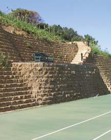
5 COVER PHOTOS: 1. Composite terraces in split fi nish (Rock Face) incorporating stairs and feature planting on terraces. 2. Terraforce blocks supporting a major road in round face fi nish. The generic designs which are described in this manual, and the design charts which are presented are suitable for construction of retaining walls within a specifi ed height range, and presume good ground conditions. The Terraforce system is suitable for retaining wall construction in a wide range of subsurface conditions which are beyond the scope of this manual. Walls with varying heights, which include geometric complications, and which involve diffi cult ground conditions can be successfully constructed using Terraforce blocks. However, the design of retaining walls for such systems should only be prepared by suitably qualifi ed design professionals. Your Terraforce supplier would be pleased to recommend an experienced, well-qualifi ed professional engineer to assist you in these matters. Terraforce walls higher than 1.2 m (4 ft) should be constructed with the assistance of, or under the supervision of experienced, qualifi ed personnel. Your Terraforce supplier can also assist you in selection of contractors, or put you in contact with experienced site personnel to train and direct others in construction techniques. DOMESTIC CUT AND FILL RETAINING 4M COMPOSITE WALL - ROUND FACE 5


6 INTRODUCTION The popularity of modular masonry units to provide the fascia of soil-reinforced segmental retaining wall systems has been growing progressively in the recent past, primarily due to their adaptability, attractiveness, ease of construction by manual means, durability and their economical cost. In common with other fascia systems, Terraforce units are durable, are capable of inclusion in retaining systems which have been constructed to heights of up to 20m (60ft), are suitable for construction in areas which are remote from the supply of conventional construction materials such as concrete, have a long service life, and provide an economical alternative to conventional construction. In addition to these proven advantages of modular masonry fascia units, Terraforce provides several unique advantages which offer an even wider range of use and enhanced fl exibility in layout design. By virtue of their unique, horizontal interlocking design, the Terraforce units can be laid in a variety of profi les ranging from straight lines to circles, concave or convex curves to serpentine walls. From vertical face walls to walls with varying degree of setback, from fully integrated stairs to free standing walls, all are created never having to cut or split a unit. Sharp or wide, convex or concave curves are formed by simply turning each unit within the half-moon interlock. Design options are limitless with Terraforce because the unique shape allows straight or stagger bond, and wall angles from vertical to a 30 slope. Several colors and two architectural textures offer unlimited design options. A unique feature of a full or partially planted wall can be attained by fi lling these hollow units with topsoil. Various plants, fl owers and ground covers can be used to create a "Living Wall" as part of an overall Landscape design. In designing gravity structures, shear keys can be employed with Terraforce units to enable the fascia to be constructed at various angles of inclination as well as to develop vertical interlock between successive courses of masonry units. This results in economical construction for the given height of the wall. The fl exibility of Terraforce allows variations in inclination from vertical to a shallow angle. Refer to the following illustrations. FEATHER OUT AT TOP VERTICAL FLUSH FACE ALT. ROUND FACE FEATHER OUT AT BOTTOM INTERNAL VERTICAL CORNER Use this detail to create stairs down a Terraforce wall. CULVERTS AND SMALL BRIDGES 6


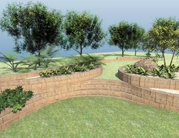

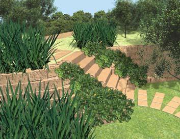
7 A DISPLAY OF UNLIMITED VERSITILITY 7
8 PRODUCT DESCRIPTION A. Technical Specification BLOCK TYPE / UNITS PER SQ.M OF WALL L13/13 L18/18 L11/11 L22/22 L15/15 L12/12 L16/16 LENGTH B(W) mm COVER A mm HEIGHT h mm WALL THICKNESS mm AVE. MASS OF BLOCK kg INFILL VOLUME m AVE. MASS OF CONCRETE kg per m² of wall (SINGLE SKIN) AVE. MASS CONSTRUCTED kg per m² of wall (SINGLE SKIN) INFILL = SOIL 1500kg/ m 3 AVE. MASS CONSTRUCTED kg per m² of wall (SINGLE SKIN) INFILL = GRAVEL 1900kg/ m 3 AVE. MASS CONSTRUCTED kg per m² of wall (SINGLE SKIN) INFILL = CONCRETE 2200kg/ m AVE. MASS CONSTRUCTED kg per m² of wall (DOUBLE SKIN) CHOOSE INFILL AND DOUBLE UP ON ABOVE FIGURE MIN. CRUSHING STRENGTH OF BLOCK UNDER IN SITU LOADING/MPa DAY CUBE STRENGTH OF CONCRETE (UNCURED) 25 MPa min MIN. FRICTIONAL RESISTANCE BETWEEN BLOCKS WITHOUT KEYS: Cf B. Quality Control Terraforce blocks are available worldwide from a number of selected, pre-approved manufacturers. Each licensed manufacturer is required to apply strict control on all aspects of production including: Physical properties and dimensions which may vary according to manufacturer; The quality of the materials used in manufacture; The maintenance of dimensional standards for product integrity, and; A comprehensive testing program on completed masonry units to confi rm that they meet or exceed the product strength requirements. These matters are addressed in a strict quality assurance protocol which has been put in place to satisfy the user that the product they use will assuredly meet the demanding strength and dimensional control requirements of the system. Quality Control test results are available upon request from your Terraforce supplier. C. Non-Standard Requirements Modifications can easily be made to the concrete mix design to suit specific applications, e.g. where a wall is to be constructed in an aggressive environment. Your Terraforce supplier will be able to assist you in meeting any special needs imposed by your own particular situation. Custom coloring is available from most manufacturers, given sufficient quantities. 8


9 PRODUCT APPLICATIONS As well as use in construction of earth retaining walls, the Terraforce masonry units can be used to construct aesthetically pleasing noise barriers and physical separation walls due to their ability to sustain vegetation. Likewise, they provide an excellent enclosing wall for raised fl ower beds as well as other landscaping features. Free-standing vertical walls, intergrated stair systems, concave, convex or serpentine walls are achieved easily using this uniquely shaped block, without ever cutting or splitting a unit. This single shaped system offers the most fl exibility available in segmental retaining wall systems. conditions. This manual has been compiled for greater wall heights or steeper wall angles necessitating earth reinforcing techniques. Using a qualifi ed engineer is recommended for these situations. A variety of uses of Terraforce units is illustrated below. Terraforce segmental retaining wall units can also be used as a fascia in side liners to water bodies such as channelized streams, artifi cial lakes and ponds, etc. In this case the Terraforce units must be fi lled with concrete or well graded gravel, the wall foundation should consist of reinforced concrete, and the foundation must be protected from scour by placing a protective blanket of rip rap at the toe of the wall. The Terraforce segmental retaining wall system uses gravity to resist the sliding action of the soil which is retained. The weight of soil-fi lled units creates suffi cient mass that under normal soil conditions the Terraforce wall can attain heights of 3m and over at varying angles and soil conditions. Separate design tables (see Appendix C ) and a comprehensive Terraforce manual is available to deal with these BEACH STABILISATION AND ACCESS HIGHWAY STABILISATION The design for such installations should be prepared by an experienced professional engineer who will provide a design which will prevent a build-up of hydrostatic pressures, fi ltration compatibility between fi lls, and infi ll soil reinforcement, on a site-specifi c basis. 9

 mattress or pad may be constructed to provide the foundation element of the wall. See the following illustration.")

10 CONSTRUCTION TECHNIQUES As noted in the introduction, the constructed Terraforce segmental retaining wall creates a fl exible gravity structure capable of withstanding repeated freeze-thaw and moderate differential movement. Where the native soil has good bearing characteristics and does not consist of frost susceptible soils (e.g. silt or topsoil) or, in situations where the native soil consists of compact sand or gravel, or stiff clay soils, shallow-bury foundations are appropriate. Where the shallow-bury option is adopted, a compacted crushed stone (granular) mattress or pad may be constructed to provide the foundation element of the wall. See the following illustration. in some countries and to a certain extent would reduce the fl exible nature of the modular retaining wall. 4.2.Drainage The design of Terraforce retaining wall systems presumes that there will be no build-up of hydrostatic pressures on the rear face of the retaining wall fascia, i.e. the retained soil will be drained. This requirement is generally achieved by placing a prism (chimney) of free draining materials on the retained side of the wall to collect water which may enter the system, and channel this to a collector drain. The collector generally disposes of the water through a series of outlets at the base of the wall or at the end of the wall. A typical system is illustrated below. If your site is in a wet condition, or is subject to high groundwater table, you should consult a qualifi ed design professional. Foundation installation is critical to the stability, appearance and service life of a Terraforce segmental retaining wall. Thus, care must be taken to remove all unstable soils from under the footing and replace with a well compacted minimum 600 mm wide granular pad with a minimum thickness of 150 mm. The fi nished grade (i.e. elevation) of the granular pad must be deep enough to allow the base course of Terraforce units to be partially buried. Normally 30mm of the base units buried per 300mm of wall height. Where the soils consist of loose sand or gravel, fi rm to stiff silty clay, or if the native soils are frostsusceptible you should seek assistance from your Terraforce supplier. In such situations a professional design would be recommended, and in many situations this will consist of a granular mattress foundation which may incorporate a cellular confi nement system. Rigid (concrete) foundation systems must always be fully protected from contact with freezing temperatures, and thus a full frost cover to the foundation is required. This option is commonly used 10


11 CONSTRUCTION TECHNIQUES In order to construct the wall to a constant gradient, each course must be set back from the underlying course by a constant width. This is known as the setback and is established in the fi eld by construction of a simple gauge, as is shown below. In order to collect and dispose of stormwater run-off, a swale or concete channel should be constructed in the backslope immediately above the crest of the retaining wall. This swale should be directed to dispose of stormwater to the local system. Often this will involve constructing the wall with a high point and providing a gradient along the crest of the wall. A typical detail of a drainage swale is given on page Shear Keys Insitu of 15 MPa, concrete or mortar may be placed where specifi ed. See illustration below. Concrete brick can be used as a shear key and will provide a consistent fascia setback. Concrete keys can substantially increase the shear resistance of walls and provide a positive vertical interlock at most wall inclinations. When walls are steeper than 75º it may be diffi cult to install the keys and a 13-16mm gravel infi ll should be specifi ed to take over the vertical interlock function where required. Horizontal interlock is achived through the ball and socket effect of the uniqely shaped Terraforce units. The end result is a mortarless dry stack system with positive interlock in all directions, unlike other systems that offer only vertical interlock. REFER TO THE TERRAFORCE CONSTRUCTION MANUAL FOR FURTHER DETAILS 4.5 Storm Water Run-off 11


12 DESIGN ALTERNATIVES 5.0 GENERAL In retaining systems which are more than 1.2 m high, the Terraforce unit can be used as part of either a gravity system or as the fascia of a geosynthetic reinforced segmental retaining wall structure or as a fascia for a cement stabilized backfi ll. this should be borne in mind when proposing rigid structures close to the top of the wall. This is why it is sometimes important to stabilise the backfi lled material with cement to ensure little or no settlement. 5.1 Gravity Retaining Walls Gravity retaining walls rely on their self-weight to resit lateral earth pressure, and such walls have been in use for centuries. Many different construction materials have been used in gravity walls. Most similar to the use of Terraforce in this situation is the (centuries old) traditional use of unreinforced bricks or dressed stone as the construction medium. In a gravity system the Terraforce masonry units can be stacked several courses deep to provide support to the forces imposed by the retained soil; the weight and geometry of the stacked units prevent the constructed wall from sliding on its base or at an intermediate height, toppling over, or rotating out of position. Unlike a reinforced concrete retaining wall, which is usually designed to resist bending moments, a gravity wall resists the thrust imposed on it by the backfi ll by virtue of its own weight only. A certain amount of movement of the wall is required to mobilise the vital resisting forces. Under normal circumstances it is assumed that the material retained is free draining and that water pressure is prevented from building up behind the embankment. Due to the inherent fl exibility of the wall, it is not usually possible to compact the backfi ll fully at construction stage. Consequently, some degree of settlement over time is inevitable and As with any retaining wall, adequate drainage of the backfi ll and equally importantly, adequate surface water removal is absolutely essential to the proper functioning of the wall. The integrity of any retaining wall is very sensitive to the angle of internal friction of the retained material. The angle of internal friction in turn is severely compromised by increased moisture content and by sub-standard compaction. Effective compaction in turn is only possible behind blocks with a closed vertical surface structure. Information relating to the design of single block width gravity retaining walls is given in the publications Guide to Terraforce L13 retaining walls and Basic design charts for Terraforce gravity walls are attached in appendix C. Designs which feature multiple rows of blocks should be prepared on a site specifi c basis by an experienced professional engineer. Attention is drawn to a Terraforce publication that may assist in the preparation of such site specifi c designs: Guide to the Design of Terraforce Retaining Walls, Oct by W G Technau of Hawkins, Hawkins & Osborn - Rivonia, South Africa. 12


13 5.2 Geosynthetic Reinforced Soil Segmental Retaining Walls Geosynthetic reinforced soil segmental retaining walls utilize reinforcing sheets of geogrid or suitable woven geotextile which are attached to the fascia and are embedded in a body of engineered fi ll. The integrated nature of the fascia and the abutting large body of reinforced soil thereby supports the applied earth forces. In this case the gravity component of the retaining wall is provided by the reinforced soil mass acting as a monolithic unit. By virtue of their inherent fl exibility, such walls are able to accommodate movement and some settlement without suffering distress. This makes the system particularly suitable for construction on (engineered) fi lled ground or in areas which may be prone to settlement effects. Also, the cost and diffi - culty of construction of such retaining walls is minimized as the need to provide full frost wall foundations can be waived in many circumstances. To this end it was necessary to conduct rigorous laboratory testing pertaining to interblock shear resistance, whole block compressive strength and geogrid pullout resistance. In the pullout tests, the primary mode of failure was rupture of the geogrid outside the blocks and performance was found to be above average, based on experience with a large number of systems tested over many years. It was thus shown that the grip obtained by clamping geogrid between blocks fi lled with coarse gravel is virtually unbeatable. The designer having chosen a geosynthetic of optimal strength can rely on Maxiforce2000 to specify the correct spacing and wall angle. Maxiforce 2000, is a user-friendly design software, capable of calculating conventional gravity as well as composite retaining walls. Utilising various Terraforce elements it is capable of performing the necessary calculations based on varying input values, design parameters and statutory requirements, complete with a printout for submission to local authorities. Multiple design charts which cover a wide variety of situations are provided on the following pages. The designs have been standardized on the use of Miragrid 2XT (specifi cation) or equivalent, and the Terraforce L18, L15 and L22 block which are 200 mm high. See notes regarding other Terraforce blocks on the following pages. The Terraforce Table Creator (available on request) will assist with basic gravity stability checks while the Maxiforce 2000 design software (free or will asisst with extended applications. 13
14 CONDITION 1 The design tables are based on the Terraforce L.18/L.22 or L15 with a block height of 200 mm. Where the Terraforce L.11 or L.13 with a block height of 225 mm are used, or the Terraforce L12 with a block height of 210mm, the lengths of the geosynthetic layers must be increased proportionately, that is by 12.5%, or 5% respectively. 5 facia setback angle 5 backslope angle nil surcharge sand and gravel backfil Terraforce Design Chart 1: Wall Inclination from Vertical: 5 degrees Setback of Each Block: * See Setback Chart on page: 34 Backfi ll Soil Friction Angle: 26 degrees Backslope Angle: 5 degrees Surcharge on Retained Soil: 0KPa 0psf Backfi ll Soil Unit Weight: 20 kn/m ³ 127pcf Geogrid Reinforcement: Miragrid 2T or equal Long Term Design Strength: 11.2kN/m 770lbs/ft Wall Toe Embedment 0.2m 8in Height of Wall (m) Height of Wall (ft) Grid Length (m) Grid Length (ft) No. of Layers of Geogrid Number of Block Courses above Base (200mm high Blocks) Georgid Layer No (Bottom Layer) Notes: 1 Detailed notes regarding the use of this design chart are given in Appendix A which should be thoroughly studied prior to construction. 2 This design applies to situations where the native soil consists of competent clay-silt-sand soil which has a safe bearing capacity of not less than 3000 p.s.f. (150 kpa) in regard to supporting foundations and can be densely compacted as a backfi ll material. 3 Geogrid reinforcement must be fully embedded between courses of Terraforce masonry units, and must be tensioned as the wall backfi ll is placed. 4 Wall foundation to comprise densely compacted well graded sand and crushed gravel material. 14
15 CONDITION 2 The design tables are based on the Terraforce L.18/L.22 or L15 with a block height of 200 mm. Where the Terraforce L.11 or L.13 with a block height of 225 mm are used, or the Terraforce L12 with a block height of 210mm, the lengths of the geosynthetic layers must be increased proportionately, that is by 12.5%, or 5% respectively. 5 facia setback angle 22 backslope angle nil surcharge sand and gravel backfil Terraforce Design Chart 2: Wall Inclination from Vertical: 5 degrees Setback of Each Block: * See Setback Chart on page: 34 Backfi ll Soil Friction Angle: 26 degrees Backslope Angle: 22 degrees Surcharge on Retained Soil: 0KPa 0psf Backfi ll Soil Unit Weight: 20 kn/m ³ 127pcf Geogrid Reinforcement: Miragrid 2T or equal Long Term Design Strength: 11.2kN/m 770lbs/ft Wall Toe Embedment 0.2m 8in Height of Wall (m) Height of Wall (ft) Grid Length (m) G6.6rid Length (ft) No. of Layers of Geogrid Number of Block Courses above Base (200mm high Blocks) Georgid Layer No (Bottom Layer) Notes: 1 Detailed notes regarding the use of this design chart are given in Appendix A which should be thoroughly studied prior to construction. 2 This design applies to situations where the native soil consists of competent clay-silt-sand soil which has a safe bearing capacity of not less than 3000 p.s.f. (150 kpa) in regard to supporting foundations and can be densely compacted as a backfi ll material. 3 Geogrid reinforcement must be fully embedded between courses of Terraforce masonry units, and must be tensioned as the wall backfi ll is placed. 4 Wall foundation to comprise densely compacted well graded sand and crushed gravel material. 15
16 CONDITION 3 The design tables are based on the Terraforce L.18/L.22 or L15 with a block height of 200 mm. Where the Terraforce L.11 or L.13 with a block height of 225 mm are used, or the Terraforce L12 with a block height of 210mm, the lengths of the geosynthetic layers must be increased proportionately, that is by 12.5%, or 5% respectively. 5 facia setback angle 5 backslope angle 10kPa (210psf) surcharge sand and gravel backfil Terraforce Design Chart 3: Wall Inclination from Vertical: 5 degrees Setback of Each Block: * See Setback Chart on page: 34 Backfi ll Soil Friction Angle: 26 degrees Backslope Angle: 5 degrees Surcharge on Retained Soil: 10KPa 210psf Backfi ll Soil Unit Weight: 20 kn/m ³ 127pcf Geogrid Reinforcement: Miragrid 2T or equal Long Term Design Strength: 11.2kN/m 770lbs/ft Wall Toe Embedment 0.2m 8in Height of Wall (m) Height of Wall (ft) Grid Length (m) Grid Length (ft) No. of Layers of Geogrid Number of Block Courses above Base (200mm high Blocks) Georgid Layer No (Bottom Layer) Notes: 1 Detailed notes regarding the use of this design chart are given in Appendix A which should be thoroughly studied prior to construction. 2 This design applies to situations where the native soil consists of competent clay-silt-sand soil which has a safe bearing capacity of not less than 3000 p.s.f. (150 kpa) in regard to supporting foundations and can be densely compacted as a backfi ll material. 3 Geogrid reinforcement must be fully embedded between courses of Terraforce masonry units, and must be tensioned as the wall backfi ll is placed. 4 Wall foundation to comprise densely compacted well graded sand and crushed gravel material. 16
17 CONDITION 4 The design tables are based on the Terraforce L.18/L.22 or L15 with a block height of 200 mm. Where the Terraforce L.11 or L.13 with a block height of 225 mm are used, or the Terraforce L12 with a block height of 210mm, the lengths of the geosynthetic layers must be increased proportionately, that is by 12.5%, or 5% respectively. 5 facia setback angle 5 backslope angle nil surcharge sand and gravel backfil Terraforce Design Chart 4: Wall Inclination from Vertical: 5 degrees Setback of Each Block: * See Setback Chart on page: 34 Backfi ll Soil Friction Angle: 31 degrees Backslope Angle: 5 degrees Surcharge on Retained Soil: 0KPa 0psf Backfi ll Soil Unit Weight: 20 kn/m ³ 127pcf Geogrid Reinforcement: Miragrid 2T or equal Long Term Design Strength: 11.2kN/m 770lbs/ft Wall Toe Embedment 0.2m 8in Height of Wall (m) Height of Wall (ft) Grid Length (m) Grid Length (ft) No. of Layers of Geogrid Number of Block Courses above Base (200mm high Blocks) Georgid Layer No (Bottom Layer) Notes: 1 Detailed notes regarding the use of this design chart are given in Appendix A which should be thoroughly studied prior to construction. 2 This design applies to situations where the native soil consists of competent clay-silt-sand soil which has a safe bearing capacity of not less than 3000 p.s.f. (150 kpa) in regard to supporting foundations and can be densely compacted as a backfi ll material. 3 Geogrid reinforcement must be fully embedded between courses of Terraforce masonry units, and must be tensioned as the wall backfi ll is placed. 4 Wall foundation to comprise densely compacted well graded sand and crushed gravel material. 17

18 CONDITION 5 The design tables are based on the Terraforce L.18/L.22 or L15 with a block height of 200 mm. Where the Terraforce L.11 or L.13 with a block height of 225 mm are used, or the Terraforce L12 with a block height of 210mm, the lengths of the geosynthetic layers must be increased proportionately, that is by 12.5%, or 5% respectively. 5 facia setback angle 22 backslope angle nil surcharge sand and gravel backfil Terraforce Design Chart 5: Wall Inclination from Vertical: 5 degrees Setback of Each Block: * See Setback Chart on page: 34 Backfi ll Soil Friction Angle: 31 degrees Backslope Angle: 22 degrees Surcharge on Retained Soil: 0KPa 0psf Backfi ll Soil Unit Weight: 20 kn/m ³ 127pcf Geogrid Reinforcement: Miragrid 2T or equal Long Term Design Strength: 11.2kN/m 770lbs/ft Wall Toe Embedment 0.2m 8in Height of Wall (m) Height of Wall (ft) Grid Length (m) Grid Length (ft) No. of Layers of Geogrid Number of Block Courses above Base (200mm high Blocks) Georgid Layer No (Bottom Layer) Notes: 1 Detailed notes regarding the use of this design chart are given in Appendix A which should be thoroughly studied prior to construction. 2 This design applies to situations where the native soil consists of competent clay-silt-sand soil which has a safe bearing capacity of not less than 3000 p.s.f. (150 kpa) in regard to supporting foundations and can be densely compacted as a backfi ll material. 3 Geogrid reinforcement must be fully embedded between courses of Terraforce masonry units, and must be tensioned as the wall backfi ll is placed. 4 Wall foundation to comprise densely compacted well graded sand and crushed gravel material. 18

19 CONDITION 6 The design tables are based on the Terraforce L.18/L.22 or L15 with a block height of 200 mm. Where the Terraforce L.11 or L.13 with a block height of 225 mm are used, or the Terraforce L12 with a block height of 210mm, the lengths of the geosynthetic layers must be increased proportionately, that is by 12.5%, or 5% respectively. 5 facia setback angle 22 backslope angle nil surcharge sand and gravel backfil Terraforce Design Chart 6: Wall Inclination from Vertical: 5 degrees Setback of Each Block: * See Setback Chart on page: 34 Backfi ll Soil Friction Angle: 31 degrees Backslope Angle: 5 degrees Surcharge on Retained Soil: 10KPa 210psf Backfi ll Soil Unit Weight: 20 kn/m ³ 127pcf Geogrid Reinforcement: Miragrid 2T or equal Long Term Design Strength: 11.2kN/m 770lbs/ft Wall Toe Embedment 0.2m 8in Height of Wall (m) Height of Wall (ft) Grid Length (m) Grid Length (ft) No. of Layers of Geogrid Number of Block Courses above Base (200mm high Blocks) Georgid Layer No (Bottom Layer) Notes: 1 Detailed notes regarding the use of this design chart are given in Appendix A which should be thoroughly studied prior to construction. 2 This design applies to situations where the native soil consists of competent clay-silt-sand soil which has a safe bearing capacity of not less than 3000 p.s.f. (150 kpa) in regard to supporting foundations and can be densely compacted as a backfi ll material. 3 Geogrid reinforcement must be fully embedded between courses of Terraforce masonry units, and must be tensioned as the wall backfi ll is placed. 4 Wall foundation to comprise densely compacted well graded sand and crushed gravel material. 19
20 CONDITION 7 The design tables are based on the Terraforce L.18/L.22 or L15 with a block height of 200 mm. Where the Terraforce L.11 or L.13 with a block height of 225 mm are used, or the Terraforce L12 with a block height of 210mm, the lengths of the geosynthetic layers must be increased proportionately, that is by 12.5%, or 5% respectively. 10 facia setback angle 5 backslope angle nil surcharge sand and gravel backfil Terraforce Design Chart 7: Wall Inclination from Vertical: 10 degrees Setback of Each Block: * See Setback Chart on page: 34 Backfi ll Soil Friction Angle: 26 degrees Backslope Angle: 5 degrees Surcharge on Retained Soil: 0KPa 0psf Backfi ll Soil Unit Weight: 20 kn/m ³ 127pcf Geogrid Reinforcement: Miragrid 2T or equal Long Term Design Strength: 11.2kN/m 770lbs/ft Wall Toe Embedment 0.2m 8in Height of Wall (m) Height of Wall (ft) Grid Length (m) Grid Length (ft) No. of Layers of Geogrid Number of Block Courses above Base (200mm high Blocks) Georgid Layer No (Bottom Layer) Notes: 1 Detailed notes regarding the use of this design chart are given in Appendix A which should be thoroughly studied prior to construction. 2 This design applies to situations where the native soil consists of competent clay-silt-sand soil which has a safe bearing capacity of not less than 3000 p.s.f. (150 kpa) in regard to supporting foundations and can be densely compacted as a backfi ll material. 3 Geogrid reinforcement must be fully embedded between courses of Terraforce masonry units, and must be tensioned as the wall backfi ll is placed. 4 Wall foundation to comprise densely compacted well graded sand and crushed gravel material. 20

21 CONDITION 8 The design tables are based on the Terraforce L.18/L.22 or L15 with a block height of 200 mm. Where the Terraforce L.11 or L.13 with a block height of 225 mm are used, or the Terraforce L12 with a block height of 210mm, the lengths of the geosynthetic layers must be increased proportionately, that is by 12.5%, or 5% respectively. 10 facia setback angle 22 backslope angle nil surcharge sand and gravel backfil Terraforce Design Chart 8: Wall Inclination from Vertical: 10 degrees Setback of Each Block: * See Setback Chart on page: 34 Backfi ll Soil Friction Angle: 26 degrees Backslope Angle: 22 degrees Surcharge on Retained Soil: 0KPa 0psf Backfi ll Soil Unit Weight: 20 kn/m ³ 127pcf Geogrid Reinforcement: Miragrid 2T or equal Long Term Design Strength: 11.2kN/m 770lbs/ft Wall Toe Embedment 0.2m 8in Height of Wall (m) Height of Wall (ft) Grid Length (m) Grid Length (ft) No. of Layers of Geogrid Number of Block Courses above Base (200mm high Blocks) Georgid Layer No (Bottom Layer) Notes: 1 Detailed notes regarding the use of this design chart are given in Appendix A which should be thoroughly studied prior to construction. 2 This design applies to situations where the native soil consists of competent clay-silt-sand soil which has a safe bearing capacity of not less than 3000 p.s.f. (150 kpa) in regard to supporting foundations and can be densely compacted as a backfi ll material. 3 Geogrid reinforcement must be fully embedded between courses of Terraforce masonry units, and must be tensioned as the wall backfi ll is placed. 4 Wall foundation to comprise densely compacted well graded sand and crushed gravel material. 21

22 CONDITION 9 The design tables are based on the Terraforce L.18/L.22 or L15 with a block height of 200 mm. Where the Terraforce L.11 or L.13 with a block height of 225 mm are used, or the Terraforce L12 with a block height of 210mm, the lengths of the geosynthetic layers must be increased proportionately, that is by 12.5%, or 5% respectively. 10 facia setback angle 5 backslope angle 10kPa (210psf) surcharge sand and gravel backfil Terraforce Design Chart 9: Wall Inclination from Vertical: 10 degrees Setback of Each Block: * See Setback Chart on page: 34 Backfi ll Soil Friction Angle: 26 degrees Backslope Angle: 5 degrees Surcharge on Retained Soil: 10KPa 21psf Backfi ll Soil Unit Weight: 20 kn/m ³ 127pcf Geogrid Reinforcement: Miragrid 2T or equal Long Term Design Strength: 11.2kN/m 770lbs/ft Wall Toe Embedment 0.2m 8in Height of Wall (m) Height of Wall (ft) Grid Length (m) Grid Length (ft) No. of Layers of Geogrid Number of Block Courses above Base (200mm high Blocks) Georgid Layer No (Bottom Layer) Notes: 1 Detailed notes regarding the use of this design chart are given in Appendix A which should be thoroughly studied prior to construction. 2 This design applies to situations where the native soil consists of competent clay-silt-sand soil which has a safe bearing capacity of not less than 3000 p.s.f. (150 kpa) in regard to supporting foundations and can be densely compacted as a backfi ll material. 3 Geogrid reinforcement must be fully embedded between courses of Terraforce masonry units, and must be tensioned as the wall backfi ll is placed. 4 Wall foundation to comprise densely compacted well graded sand and crushed gravel material. 22
23 CONDITION 10 The design tables are based on the Terraforce L.18/L.22 or L15 with a block height of 200 mm. Where the Terraforce L.11 or L.13 with a block height of 225 mm are used, or the Terraforce L12 with a block height of 210mm, the lengths of the geosynthetic layers must be increased proportionately, that is by 12.5%, or 5% respectively. 10 facia setback angle 5 backslope angle nil surcharge sand and gravel backfil Terraforce Design Chart 10: Wall Inclination from Vertical: 5 degrees Setback of Each Block: * See Setback Chart on page: 34 Backfi ll Soil Friction Angle: 31 degrees Backslope Angle: 5 degrees Surcharge on Retained Soil: 0KPa 0psf Backfi ll Soil Unit Weight: 20 kn/m ³ 127pcf Geogrid Reinforcement: Miragrid 2T or equal Long Term Design Strength: 11.2kN/m 770lbs/ft Wall Toe Embedment 0.2m 8in Height of Wall (m) Height of Wall (ft) Grid Length (m) Grid Length (ft) No. of Layers of Geogrid Number of Block Courses above Base (200mm high Blocks) Georgid Layer No (Bottom Layer) Notes: 1 Detailed notes regarding the use of this design chart are given in Appendix A which should be thoroughly studied prior to construction. 2 This design applies to situations where the native soil consists of competent clay-silt-sand soil which has a safe bearing capacity of not less than 3000 p.s.f. (150 kpa) in regard to supporting foundations and can be densely compacted as a backfi ll material. 3 Geogrid reinforcement must be fully embedded between courses of Terraforce masonry units, and must be tensioned as the wall backfi ll is placed. 4 Wall foundation to comprise densely compacted well graded sand and crushed gravel material. 23
24 CONDITION 11 The design tables are based on the Terraforce L.18/L.22 or L15 with a block height of 200 mm. Where the Terraforce L.11 or L.13 with a block height of 225 mm are used, or the Terraforce L12 with a block height of 210mm, the lengths of the geosynthetic layers must be increased proportionately, that is by 12.5%, or 5% respectively. 10 facia setback angle 22 backslope angle nil surcharge sand and gravel backfil Terraforce Design Chart 11: Wall Inclination from Vertical: 10 degrees Setback of Each Block: * See Setback Chart on page: 34 Backfi ll Soil Friction Angle: 31 degrees Backslope Angle: 22 degrees Surcharge on Retained Soil: 0KPa 0psf Backfi ll Soil Unit Weight: 20 kn/m ³ 127pcf Geogrid Reinforcement: Miragrid 2T or equal Long Term Design Strength: 11.2kN/m 770lbs/ft Wall Toe Embedment 0.2m 8in Height of Wall (m) Height of Wall (ft) Grid Length (m) Grid Length (ft) No. of Layers of Geogrid Number of Block Courses above Base (200mm high Blocks) Georgid Layer No (Bottom Layer) Notes: 1 Detailed notes regarding the use of this design chart are given in Appendix A which should be thoroughly studied prior to construction. 2 This design applies to situations where the native soil consists of competent clay-silt-sand soil which has a safe bearing capacity of not less than 3000 p.s.f. (150 kpa) in regard to supporting foundations and can be densely compacted as a backfi ll material. 3 Geogrid reinforcement must be fully embedded between courses of Terraforce masonry units, and must be tensioned as the wall backfi ll is placed. 4 Wall foundation to comprise densely compacted well graded sand and crushed gravel material. 24
25 CONDITION 12 The design tables are based on the Terraforce L.18/L.22 or L15 with a block height of 200 mm. Where the Terraforce L.11 or L.13 with a block height of 225 mm are used, or the Terraforce L12 with a block height of 210mm, the lengths of the geosynthetic layers must be increased proportionately, that is by 12.5%, or 5% respectively. 10 facia setback angle 5 backslope angle 10kPa (210psf) surcharge sand and gravel backfil Terraforce Design Chart 12: Wall Inclination from Vertical: 10 degrees Setback of Each Block: * See Setback Chart on page: 34 Backfi ll Soil Friction Angle: 31 degrees Backslope Angle: 5 degrees Surcharge on Retained Soil: 10KPa 210psf Backfi ll Soil Unit Weight: 20 kn/m ³ 127pcf Geogrid Reinforcement: Miragrid 2T or equal Long Term Design Strength: 11.2kN/m 770lbs/ft Wall Toe Embedment 0.2m 8in Height of Wall (m) Height of Wall (ft) Grid Length (m) Grid Length (ft) No. of Layers of Geogrid Number of Block Courses above Base (200mm high Blocks) Georgid Layer No (Bottom Layer) Notes: 1 Detailed notes regarding the use of this design chart are given in Appendix A which should be thoroughly studied prior to construction. 2 This design applies to situations where the native soil consists of competent clay-silt-sand soil which has a safe bearing capacity of not less than 3000 p.s.f. (150 kpa) in regard to supporting foundations and can be densely compacted as a backfi ll material. 3 Geogrid reinforcement must be fully embedded between courses of Terraforce masonry units, and must be tensioned as the wall backfi ll is placed. 4 Wall foundation to comprise densely compacted well graded sand and crushed gravel material. 25
26 CONDITION 13 The design tables are based on the Terraforce L.18/L.22 or L15 with a block height of 200 mm. Where the Terraforce L.11 or L.13 with a block height of 225 mm are used, or the Terraforce L12 with a block height of 210mm, the lengths of the geosynthetic layers must be increased proportionately, that is by 12.5%, or 5% respectively. 20 facia setback angle 5 backslope angle nil surcharge sand and gravel backfil Terraforce Design Chart 13: Wall Inclination from Vertical: 20 degrees Setback of Each Block: * See Setback Chart on page: 34 Backfi ll Soil Friction Angle: 26 degrees Backslope Angle: 5 degrees Surcharge on Retained Soil: 0KPa 0psf Backfi ll Soil Unit Weight: 20 kn/m ³ 127pcf Geogrid Reinforcement: Miragrid 2T or equal Long Term Design Strength: 11.2kN/m 770lbs/ft Wall Toe Embedment 0.2m 8in Height of Wall (m) Height of Wall (ft) Grid Length (m) Grid Length (ft) No. of Layers of Geogrid Number of Block Courses above Base (200mm high Blocks) Georgid Layer No (Bottom Layer) Notes: 1 Detailed notes regarding the use of this design chart are given in Appendix A which should be thoroughly studied prior to construction. 2 This design applies to situations where the native soil consists of competent clay-silt-sand soil which has a safe bearing capacity of not less than 3000 p.s.f. (150 kpa) in regard to supporting foundations and can be densely compacted as a backfi ll material. 3 Geogrid reinforcement must be fully embedded between courses of Terraforce masonry units, and must be tensioned as the wall backfi ll is placed. 4 Wall foundation to comprise densely compacted well graded sand and crushed gravel material. 26

27 CONDITION 14 The design tables are based on the Terraforce L.18/L.22 or L15 with a block height of 200 mm. Where the Terraforce L.11 or L.13 with a block height of 225 mm are used, or the Terraforce L12 with a block height of 210mm, the lengths of the geosynthetic layers must be increased proportionately, that is by 12.5%, or 5% respectively. 20 facia setback angle 22 backslope angle nil surcharge sand and gravel backfil Terraforce Design Chart 14: Wall Inclination from Vertical: 20 degrees Setback of Each Block: * See Setback Chart on page: 34 Backfi ll Soil Friction Angle: 26 degrees Backslope Angle: 22 degrees Surcharge on Retained Soil: 0KPa 0psf Backfi ll Soil Unit Weight: 20 kn/m ³ 127pcf Geogrid Reinforcement: Miragrid 2T or equal Long Term Design Strength: 11.2kN/m 770lbs/ft Wall Toe Embedment 0.2m 8in Height of Wall (m) Height of Wall (ft) Grid Length (m) Grid Length (ft) No. of Layers of Geogrid Number of Block Courses above Base (200mm high Blocks) Georgid Layer No (Bottom Layer) Notes: 1 Detailed notes regarding the use of this design chart are given in Appendix A which should be thoroughly studied prior to construction. 2 This design applies to situations where the native soil consists of competent clay-silt-sand soil which has a safe bearing capacity of not less than 3000 p.s.f. (150 kpa) in regard to supporting foundations and can be densely compacted as a backfi ll material. 3 Geogrid reinforcement must be fully embedded between courses of Terraforce masonry units, and must be tensioned as the wall backfi ll is placed. 4 Wall foundation to comprise densely compacted well graded sand and crushed gravel material. 27
28 CONDITION 15 The design tables are based on the Terraforce L.18/L.22 or L15 with a block height of 200 mm. Where the Terraforce L.11 or L.13 with a block height of 225 mm are used, or the Terraforce L12 with a block height of 210mm, the lengths of the geosynthetic layers must be increased proportionately, that is by 12.5%, or 5% respectively. 20 facia setback angle 5 backslope angle 10kPa (210psf) surcharge sand and gravel backfil Terraforce Design Chart 15: Wall Inclination from Vertical: 20 degrees Setback of Each Block: * See Setback Chart on page: 34 Backfi ll Soil Friction Angle: 26 degrees Backslope Angle: 5 degrees Surcharge on Retained Soil: 10KPa 210psf Backfi ll Soil Unit Weight: 20 kn/m ³ 127pcf Geogrid Reinforcement: Miragrid 2T or equal Long Term Design Strength: 11.2kN/m 770lbs/ft Wall Toe Embedment 0.2m 8in Height of Wall (m) Height of Wall (ft) Grid Length (m) Grid Length (ft) No. of Layers of Geogrid Number of Block Courses above Base (200mm high Blocks) Georgid Layer No (Bottom Layer) Notes: 1 Detailed notes regarding the use of this design chart are given in Appendix A which should be thoroughly studied prior to construction. 2 This design applies to situations where the native soil consists of competent clay-silt-sand soil which has a safe bearing capacity of not less than 3000 p.s.f. (150 kpa) in regard to supporting foundations and can be densely compacted as a backfi ll material. 3 Geogrid reinforcement must be fully embedded between courses of Terraforce masonry units, and must be tensioned as the wall backfi ll is placed. 4 Wall foundation to comprise densely compacted well graded sand and crushed gravel material. 28
29 CONDITION 16 The design tables are based on the Terraforce L.18/L.22 or L15 with a block height of 200 mm. Where the Terraforce L.11 or L.13 with a block height of 225 mm are used, or the Terraforce L12 with a block height of 210mm, the lengths of the geosynthetic layers must be increased proportionately, that is by 12.5%, or 5% respectively. 20 facia setback angle 5 backslope angle nil surcharge sand and gravel backfil Terraforce Design Chart 16: Wall Inclination from Vertical: 20 degrees Setback of Each Block: * See Setback Chart on page: 34 Backfi ll Soil Friction Angle: 31 degrees Backslope Angle: 5 degrees Surcharge on Retained Soil: 0KPa 0psf Backfi ll Soil Unit Weight: 20 kn/m ³ 127pcf Geogrid Reinforcement: Miragrid 2T or equal Long Term Design Strength: 11.2kN/m 770lbs/ft Wall Toe Embedment 0.2m 8in Height of Wall (m) Height of Wall (ft) Grid Length (m) Grid Length (ft) No. of Layers of Geogrid Number of Block Courses above Base (200mm high Blocks) Georgid Layer No (Bottom Layer) Notes: 1 Detailed notes regarding the use of this design chart are given in Appendix A which should be thoroughly studied prior to construction. 2 This design applies to situations where the native soil consists of competent clay-silt-sand soil which has a safe bearing capacity of not less than 3000 p.s.f. (150 kpa) in regard to supporting foundations and can be densely compacted as a backfi ll material. 3 Geogrid reinforcement must be fully embedded between courses of Terraforce masonry units, and must be tensioned as the wall backfi ll is placed. 4 Wall foundation to comprise densely compacted well graded sand and crushed gravel material. 29
30 CONDITION 17 The design tables are based on the Terraforce L.18/L.22 or L15 with a block height of 200 mm. Where the Terraforce L.11 or L.13 with a block height of 225 mm are used, or the Terraforce L12 with a block height of 210mm, the lengths of the geosynthetic layers must be increased proportionately, that is by 12.5%, or 5% respectively. 20 facia setback angle 22 backslope angle nil surcharge sand and gravel backfil Terraforce Design Chart 17: Wall Inclination from Vertical: 20 degrees Setback of Each Block: * See Setback Chart on page: 34 Backfi ll Soil Friction Angle: 31 degrees Backslope Angle: 22 degrees Surcharge on Retained Soil: 0KPa 0psf Backfi ll Soil Unit Weight: 20 kn/m ³ 127pcf Geogrid Reinforcement: Miragrid 2T or equal Long Term Design Strength: 11.2kN/m 770lbs/ft Wall Toe Embedment 0.2m 8in Height of Wall (m) Height of Wall (ft) Grid Length (m) Grid Length (ft) No. of Layers of Geogrid Number of Block Courses above Base (200mm high Blocks) Georgid Layer No (Bottom Layer) Notes: 1 Detailed notes regarding the use of this design chart are given in Appendix A which should be thoroughly studied prior to construction. 2 This design applies to situations where the native soil consists of competent clay-silt-sand soil which has a safe bearing capacity of not less than 3000 p.s.f. (150 kpa) in regard to supporting foundations and can be densely compacted as a backfi ll material. 3 Geogrid reinforcement must be fully embedded between courses of Terraforce masonry units, and must be tensioned as the wall backfi ll is placed. 4 Wall foundation to comprise densely compacted well graded sand and crushed gravel material. 30
31 CONDITION 18 The design tables are based on the Terraforce L.18/L.22 or L15 with a block height of 200 mm. Where the Terraforce L.11 or L.13 with a block height of 225 mm are used, or the Terraforce L12 with a block height of 210mm, the lengths of the geosynthetic layers must be increased proportionately, that is by 12.5%, or 5% respectively. 20 facia setback angle 5 backslope angle 10kPa (210psf) surcharge sand and gravel backfil Terraforce Design Chart 18: Wall Inclination from Vertical: 20 degrees Setback of Each Block: * See Setback Chart on page: 34 Backfi ll Soil Friction Angle: 31 degrees Backslope Angle: 22 degrees Surcharge on Retained Soil: 10KPa 210psf Backfi ll Soil Unit Weight: 20 kn/m ³ 127pcf Geogrid Reinforcement: Miragrid 2T or equal Long Term Design Strength: 11.2kN/m 770lbs/ft Wall Toe Embedment 0.2m 8in Height of Wall (m) Height of Wall (ft) Grid Length (m) Grid Length (ft) No. of Layers of Geogrid Number of Block Courses above Base (200mm high Blocks) Georgid Layer No (Bottom Layer) Notes: 1 Detailed notes regarding the use of this design chart are given in Appendix A which should be thoroughly studied prior to construction. 2 This design applies to situations where the native soil consists of competent clay-silt-sand soil which has a safe bearing capacity of not less than 3000 p.s.f. (150 kpa) in regard to supporting foundations and can be densely compacted as a backfi ll material. 3 Geogrid reinforcement must be fully embedded between courses of Terraforce masonry units, and must be tensioned as the wall backfi ll is placed. 4 Wall foundation to comprise densely compacted well graded sand and crushed gravel material.. 31
32 CONDITION 19 The design tables are based on the Terraforce L.18/L.22 or L15 with a block height of 200 mm. Where the Terraforce L.11 or L.13 with a block height of 225 mm are used, or the Terraforce L12 with a block height of 210mm, the lengths of the geosynthetic layers must be increased proportionately, that is by 12.5%, or 5% respectively. 30 facia setback angle 5 backslope angle nil surcharge sand and gravel backfil Terraforce Design Chart 19: Wall Inclination from Vertical: 30 degrees Setback of Each Block: * See Setback Chart on page: 34 Backfi ll Soil Friction Angle: 26 degrees Backslope Angle: 5 degrees Surcharge on Retained Soil: 0KPa 0psf Backfi ll Soil Unit Weight: 20 kn/m ³ 127pcf Geogrid Reinforcement: Miragrid 2T or equal Long Term Design Strength: 11.2kN/m 770lbs/ft Wall Toe Embedment 0.2m 8in Height of Wall (m) Height of Wall (ft) Grid Length (m) Grid Length (ft) No. of Layers of Geogrid Number of Block Courses above Base (200mm high Blocks) Georgid Layer No (Bottom Layer) Notes: 1 Detailed notes regarding the use of this design chart are given in Appendix A which should be thoroughly studied prior to construction. 2 This design applies to situations where the native soil consists of competent clay-silt-sand soil which has a safe bearing capacity of not less than 3000 p.s.f. (150 kpa) in regard to supporting foundations and can be densely compacted as a backfi ll material. 3 Geogrid reinforcement must be fully embedded between courses of Terraforce masonry units, and must be tensioned as the wall backfi ll is placed. 4 Wall foundation to comprise densely compacted well graded sand and crushed gravel material. 32
33 CONDITION 20 The design tables are based on the Terraforce L.18/L.22 or L15 with a block height of 200 mm. Where the Terraforce L.11 or L.13 with a block height of 225 mm are used, or the Terraforce L12 with a block height of 210mm, the lengths of the geosynthetic layers must be increased proportionately, that is by 12.5%, or 5% respectively. 30 facia setback angle 22 backslope angle nil surcharge sand and gravel backfil Terraforce Design Chart 20: Wall Inclination from Vertical: 30 degrees Setback of Each Block: * See Setback Chart on page: 34 Backfi ll Soil Friction Angle: 26 degrees Backslope Angle: 22 degrees Surcharge on Retained Soil: 0KPa 0psf Backfi ll Soil Unit Weight: 20 kn/m ³ 127pcf Geogrid Reinforcement: Miragrid 2T or equal Long Term Design Strength: 11.2kN/m 770lbs/ft Wall Toe Embedment 0.2m 8in Height of Wall (m) Height of Wall (ft) Grid Length (m) Grid Length (ft) No. of Layers of Geogrid Number of Block Courses above Base (200mm high Blocks) Georgid Layer No (Bottom Layer) Notes: 1 Detailed notes regarding the use of this design chart are given in Appendix A which should be thoroughly studied prior to construction. 2 This design applies to situations where the native soil consists of competent clay-silt-sand soil which has a safe bearing capacity of not less than 3000 p.s.f. (150 kpa) in regard to supporting foundations and can be densely compacted as a backfi ll material. 3 Geogrid reinforcement must be fully embedded between courses of Terraforce masonry units, and must be tensioned as the wall backfi ll is placed. 4 Wall foundation to comprise densely compacted well graded sand and crushed gravel material. 33

34 CONDITION 21 The design tables are based on the Terraforce L.18/L.22 or L15 with a block height of 200 mm. Where the Terraforce L.11 or L.13 with a block height of 225 mm are used, or the Terraforce L12 with a block height of 210mm, the lengths of the geosynthetic layers must be increased proportionately, that is by 12.5%, or 5% respectively. 30 facia setback angle 5 backslope angle 10kPa (210psf) surcharge sand and gravel backfil Terraforce Design Chart 21: Wall Inclination from Vertical: 30 degrees Setback of Each Block: * See Setback Chart on page: 34 Backfi ll Soil Friction Angle: 26 degrees Backslope Angle: 5 degrees Surcharge on Retained Soil: 10KPa 210psf Backfi ll Soil Unit Weight: 20 kn/m ³ 127pcf Geogrid Reinforcement: Miragrid 2T or equal Long Term Design Strength: 11.2kN/m 770lbs/ft Wall Toe Embedment 0.2m 8in Height of Wall (m) Height of Wall (ft) Grid Length (m) Grid Length (ft) No. of Layers of Geogrid Number of Block Courses above Base (200mm high Blocks) Georgid Layer No (Bottom Layer) Notes: 1 Detailed notes regarding the use of this design chart are given in Appendix A which should be thoroughly studied prior to construction. 2 This design applies to situations where the native soil consists of competent clay-silt-sand soil which has a safe bearing capacity of not less than 3000 p.s.f. (150 kpa) in regard to supporting foundations and can be densely compacted as a backfi ll material. 3 Geogrid reinforcement must be fully embedded between courses of Terraforce masonry units, and must be tensioned as the wall backfi ll is placed. 4 Wall foundation to comprise densely compacted well graded sand and crushed gravel material. 34
35 CONDITION 22 The design tables are based on the Terraforce L.18/L.22 or L15 with a block height of 200 mm. Where the Terraforce L.11 or L.13 with a block height of 225 mm are used, or the Terraforce L12 with a block height of 210mm, the lengths of the geosynthetic layers must be increased proportionately, that is by 12.5%, or 5% respectively. 30 facia setback angle 5 backslope angle nil surcharge sand and gravel backfil Terraforce Design Chart 22: Wall Inclination from Vertical: 30 degrees Setback of Each Block: * See Setback Chart on page: 34 Backfi ll Soil Friction Angle: 31 degrees Backslope Angle: 5 degrees Surcharge on Retained Soil: 0KPa 0psf Backfi ll Soil Unit Weight: 20 kn/m ³ 127pcf Geogrid Reinforcement: Miragrid 2T or equal Long Term Design Strength: 11.2kN/m 770lbs/ft Wall Toe Embedment 0.2m 8in Height of Wall (m) Height of Wall (ft) Grid Length (m) Grid Length (ft) No. of Layers of Geogrid Number of Block Courses above Base (200mm high Blocks) Georgid Layer No (Bottom Layer) Notes: 1 Detailed notes regarding the use of this design chart are given in Appendix A which should be thoroughly studied prior to construction. 2 This design applies to situations where the native soil consists of competent clay-silt-sand soil which has a safe bearing capacity of not less than 3000 p.s.f. (150 kpa) in regard to supporting foundations and can be densely compacted as a backfi ll material. 3 Geogrid reinforcement must be fully embedded between courses of Terraforce masonry units, and must be tensioned as the wall backfi ll is placed. 4 Wall foundation to comprise densely compacted well graded sand and crushed gravel material. 35

36 CONDITION 23 The design tables are based on the Terraforce L.18/L.22 or L15 with a block height of 200 mm. Where the Terraforce L.11 or L.13 with a block height of 225 mm are used, or the Terraforce L12 with a block height of 210mm, the lengths of the geosynthetic layers must be increased proportionately, that is by 12.5%, or 5% respectively. 30 facia setback angle 22 backslope angle nil surcharge sand and gravel backfil Terraforce Design Chart 23: Wall Inclination from Vertical: 30 degrees Setback of Each Block: * See Setback Chart on page: 34 Backfi ll Soil Friction Angle: 31 degrees Backslope Angle: 22 degrees Surcharge on Retained Soil: 0KPa 0psf Backfi ll Soil Unit Weight: 20 kn/m ³ 127pcf Geogrid Reinforcement: Miragrid 2T or equal Long Term Design Strength: 11.2kN/m 770lbs/ft Wall Toe Embedment 0.2m 8in * SEE SETBACK CHART ON PAGE Height of Wall (m) Height of Wall (ft) Grid Length (m) Grid Length (ft) No. of Layers of Geogrid Number of Block Courses above Base (200mm high Blocks) Georgid Layer No (Bottom Layer) Notes: 1 Detailed notes regarding the use of this design chart are given in Appendix A which should be thoroughly studied prior to construction. 2 This design applies to situations where the native soil consists of competent clay-silt-sand soil which has a safe bearing capacity of not less than 3000 p.s.f. (150 kpa) in regard to supporting foundations and can be densely compacted as a backfi ll material. 3 Geogrid reinforcement must be fully embedded between courses of Terraforce masonry units, and must be tensioned as the wall backfi ll is placed. 4 Wall foundation to comprise densely compacted well graded sand and crushed gravel material. 36
37 CONDITION 24 The design tables are based on the Terraforce L.18/L.22 or L15 with a block height of 200 mm. Where the Terraforce L.11 or L.13 with a block height of 225 mm are used, or the Terraforce L12 with a block height of 210mm, the lengths of the geosynthetic layers must be increased proportionately, that is by 12.5%, or 5% respectively. 30 facia setback angle 5 backslope angle 10kPa (210psf) surcharge sand and gravel backfil Terraforce Design Chart 24: Wall Inclination from Vertical: 30 degrees Setback of Each Block: * See Setback Chart on page: 34 Backfi ll Soil Friction Angle: 31 degrees Backslope Angle: 5 degrees Surcharge on Retained Soil: 10KPa 210psf Backfi ll Soil Unit Weight: 20 kn/m ³ 127pcf Geogrid Reinforcement: Miragrid 2T or equal Long Term Design Strength: 11.2kN/m 770lbs/ft Wall Toe Embedment 0.2m 8in Height of Wall (m) Height of Wall (ft) Grid Length (m) Grid Length (ft) No. of Layers of Geogrid Number of Block Courses above Base (200mm high Blocks) Georgid Layer No (Bottom Layer) Notes: 1 Detailed notes regarding the use of this design chart are given in Appendix A which should be thoroughly studied prior to construction. 2 This design applies to situations where the native soil consists of competent clay-silt-sand soil which has a safe bearing capacity of not less than 3000 p.s.f. (150 kpa) in regard to supporting foundations and can be densely compacted as a backfi ll material. 3 Geogrid reinforcement must be fully embedded between courses of Terraforce masonry units, and must be tensioned as the wall backfi ll is placed. 4 Wall foundation to comprise densely compacted well graded sand and crushed gravel material. 37
38 Use of Design Charts This manual provides a total of 24 design charts which relate to the following situations : 1. INCLINATION OF TERRAFORCE WALL TO VERTICAL 5 charts 1 through 6 10 charts 7 through charts 13 through charts 19 through USE OF DIFFERENT WALL BACKFILL MATE- RIALS Soil friction angle of 26 refers to soil consisting of densely compacted silty clay, silt or silty sand. Soil friction angle of 31 refers to soil consisting of densely compacted sand or gravelly sand. Backfi ll materials should be placed in thin lifts 150 to 200 mm and thoroughly and uniformly compacted to a dense state of compaction (not less than 95% of the material's standard Proctor maximum dry density). The drainage fi ll will consist of well-graded sand and gravel, or clear crushed stone placed adjacent to the wall fascia, with each lift. The width of the drainage fi ll is to be at least 0.3 m. 3. GEOGRID REINFORCEMENT For various heights of wall ranging from 1.4 to 4.0 m the charts provide : The number of layers of geogrid (grid) reinforcement required; The vertical height increments at which the grid sheets are laid, described by the course below; The length of grid, measured inwards from the face of the wall. The designs have been standardized on the use of Miragrid 2T or equivalent i.e. Restrain 50 etc. For details: This material is a high quality, multi-strand polyester geogrid which is particularly suitable for use in wall construction as it can be rolled out along the length of the wall rather than being cut transversely. When laid in this manner the main (strongest) direction of this Miragrid reinforcement is perpendicular to the face of the wall. Miragrid rolls can be cut into the exact widths required by the design. Alternatively Miragrid 5T or equivalent can be used. In this case the Miragrid 5T is rolled perpendicular to the face of the wall and cut to the required length. at the fascia. The next course of Terraforce blocks is laid above the geogrid and infi lled, the geogrid is extended over its designed width and tensioned, and the tension is held by placing backfi ll material (for the next lift) on the edge remote from the wall. The next lift of backfi ll is then laid and densely compacted. 4. BACKSLOPE Charts are provided for the following conditions Backslope above crest of wall 5 to horizontal (1V:11H slope); Backslope above crest of wall 22 to horizontal (1V:2.5H slope); Backslope above crest of wall at 5 to horizontal and able to sustain a surcharge load (imposed pressure) of 10 kpa, this is adequate to allow for parking passenger cars. 5. FOUNDATION CONDITIONS It is assumed that the soil which supports the wall foundation consists of competent material capable of supporting a load of 150 kpa. Soils such as stiff clay soils, and compact to dense silty sand are examples of competent materials. In the event that weaker soils are found, or that the foundation soil is a frost susceptible material (e.g. silt), you should contact your Terraforce distributor who will refer you to an experienced design professional. 6. GLOBAL STABILITY Potential global failure mechanisms are not addressed directly in this design manual but should be considered in the design of reinforced soil walls. This is the same as would be in the case in any retaining wall design whether reinforced soil or conventional. Global instability may be associated with potential failure, surfaces passing through the backfi ll soil and into the foundation soils beyond the limits of the reinforced soil zone. Therefore, it is prudent to perform this global analysis prior to undertaking detailed wall calculations. Calculation of the factor of safety against global failure modes should be undertaken by a competent geotechnical engineer familiar with the subsurface conditions at the site. When the grids are laid to reinforce the Terraforce wall fascia, the level of the compacted backfi ll is raised to the design geogrid installation level and is installed fi rst 38

39 APPENDIX A In most cases these analyses can be carried out using conventional limit equilibrium slope stability methods of analysis as given in standard geotechnical engineering textbooks. External failure mechanisms consider the stability of an equivalent gravity structure comprising the facing units, geosynthetic reinforcement, and reinforced soil fi ll. Internal stability calculations are restricted to potential failure mechanisms within the reinforced soil zone. Local stability calculations are focused on the stability of the dry-stacked column that forms the facing and the connections with the reinforcement layers. Design of the maximum unreinforced wall height at the top of the structure is carried out using the stability analysis and factors of safety recommended for conventional (gravity) segmental retaining walls. Not illustrated in this fi gure is the requirement that global stability of the structure be satisfi ed as is the case for all retaining wall systems. Conventional slope stability methods of analysis that have been modifi ed to include the stabilizing infl uence of horizontal layers of geosynthetic reinforcement can be used for this purpose. The principal components of a geosynthetic reinforced soil segmental retaining wall and the earth pressures which act on that wall are illustrated in the previous fi gure. For a detailed review of design methodology, the reader is referred to the following publications Guide to the Design of Terraforce L 13 Retaining Walls, Hawkins, Hawkins and Osborn, 1992 available at Guide to the Design of Terraforce L18 Retaining Walls, Steffen, Robertson and Kirsten, Bathurst, RJ., Geosynthetics for Reinforcement Applications in Retaining Walls, Proc. 44th Can. Geotech. Conf Bathurst, RJ., Simac M.R and Berg, RR, Review of NCMA Segmental Retaining Wall Design Manual for Geosynthetic Reinforced Structures, Transportation Research Record No. 1414, Mitchell, J.K. and Villet, W.C.B. (Eds), Reinforce ment Earth Slopes and Embankments, National Cooperative Highway Research Program Report No. 290, NCMA Design Manual for Segmental Retaining Walls, First Edition, The engineering calculations and design drawings for geosynthetic reinforced walls were prepared jointly by Dr. Richard J. Bathurst of Royal Military College, Kingston, Ontario and Colin Alston of Alston Associates Inc., Markham Ontario. The basic design charts for Terraforce gravity Walls in Appendix C were prepared by Johan Joubert of Foundation and Slope Stability Engineering (PTY) LTD Pretoria, South Africa. CAUTIONARY NOTE! Insuffi cient professional design and supervision input occasionally result in these shortfalls: Saturated backfill - lack of drainage above and behind the wall Insufficient constructed mass - no or negligible design input Limited bearing capacity - poor or saturated founding conditions Design angle and height exceeded - lack of supervision Settlement - substandard backfi ll or inadequate compaction Face connection failure - poor connection between block and reinforcing fabrics Undermining - excavation close to the wall foundation Excessive loading - not accounted for in original design 39
40 40 APPENDIX B Design Methods for Geosynthetic Reinforced Soil Retaining Walls The design of the soil reinforced retaining wall systems takes into account the potential failure mechanisms illustrated below.

41 APPENDIX C Basic design table for mass gravity retaining walls. BLOCK L13 L13 ROCKFACE CHECK WITH LOCAL SUPPLIER FOR AVAILABILITY 41

42 APPENDIX C Basic design table for mass gravity retaining walls. BLOCK L18 42


43 APPENDIX C Basic design table for mass gravity retaining walls. BLOCK L11 43

44 APPENDIX C Basic design table for mass gravity retaining walls. BLOCK L22 44
45 APPENDIX C Basic design table for mass gravity retaining walls. BLOCK L15 45
46 APPENDIX C Basic design table for mass gravity retaining walls. BLOCK L12 46
47 APPENDIX C Basic design table for mass gravity retaining walls. BLOCK L16 47
48 48 SUBMISSION SHEET 1 for mass gravity retaining walls.

49 SUBMISSION SHEET 2 for composite retaing walls. 49
50 FULL BILL OF QUANTITY (Example) Item Description Unit Quantity Rate Amount 1 Site establishment sum 1 2 Contractual requirements sum 1 3 Excavate and trim to lines and grades for foundations. m ³ 4 Excavate material behind proposed wall face to specifi ed width and spoil/stockpile (delete were not aplicable), to allow for placement of geosynthetic reinforcement and imported fi ll m ³ 5 Trimming of batter faces to correct angle and embankment preparation work prior to placement of retaining wall blocks and fi ll m ³ 6 Supply and place 20Mpa concrete in foundations as per detail, or 7 Supply and place crushed stone / gravel pad in foundations as per detail 8 Supply and place steel reinforcement in foundations and walls if specifi ed 9 Supply and install TERRAFORCE BLOCKS TYPE with a minimum constructed mass of kg/m² including a minimum 300mm wide coarse drainage layer behind the blocks. 10 Granular fi ll from stockpile: Supply, spread in layers less than 150mm thick, water to optimum moisture content and compact fi ll to no less than 90% Mod AASHTO 11 Granular fi ll supplied by others to the workface: Supply, spread in layers less than 150mm thick, water to optimum moisture content and compact fi ll to no less than 90% Mod AASHTO 12 Supply, install at specifi ed elevation and orientation geosynthetic reinforcement type, as directed by site enginer. Fill shall be placed, spread and compacted in such a manner that eliminates the developement of wrinkles and/or movement of geosynthetic reinforcement. 13 Supply, install at specifi ed elevation perforated drainage collection pipe type to maintain gravity fl ow of water to outside of reinforced soil zone. 14 Wrap drainage collection pipe and 21mm drainage aggregate in drainage material type 15 Supply and install drainage fi lter fabric type along excavated batter as specifi ed 16 Supply and lay Findrain / Wickdrain...mm wide at 45 angles along excavated batter at 2m centres, as per the specifi cations. Connect to perforated collector pipe. Pipe measured under item Fill retaining blocks with garden soil lightly tamped as the work m ³ proceeds 18 Professional Engineer s design fees % 19 Professional Engineer s supervision fees sum m ³ m ³ ton m ² m ³ m ³ m ² m m m ² m 50
51 FOR TERRAFORCE RECOMMENDED SPECIFICATIONS, EVALUATION REPORT, DESIGN QUESTIONAIRES, SPARE SUBMISSION SHEETS, BILL OF QUANTITIES AND BRIEF Q & A SECTION, GO TO Disclaimer Although every reasonable effort has been made to ensure that the technical information and the design procedures presented in this Guide are correct, neither Terraforce CC and any manufacturer of the product, nor their consultants, who have contributed to the preparation of these guidelines, will be held liable for any loss or damage, either direct or consequential, arising from any failure or collapse of a wall of any description constructed with Terraforce precast concrete blocks. As with any structure, the design of Terraforce retaining walls should only be undertaken by suitably qualifi ed and experienced designers with due cognisance being taken of the specifi c geotechnical conditions and vital soil parameters pertaining to the site. 51


52 BEFORE... AND AFTER HOUSE KANONBERG DIE KELDERS CAVE OASIS - SOUND BARRIER 52


53 BEFORE... AND AFTER HOUSE KANONBERG MOUNTAIN RETREAT DURBAN LAGUNA BEACH 53

54 54
55 55


56
Tasman Retaining Wall
 Tasman Retaining Wall EVALUATION AND INSTALLATION GUIDE Landscaping Tasman Retaining Wall Evaluation and Installation Guide This installation guide demonstrates the basics on how to construct: A. Tasman
Design and Installation Guidelines for Retaining Walls. 1 P age. Geo Products, LLC 8615 Golden Spike Lane Houston, TX Phone:
 Design and Installation Guidelines for Retaining Walls 1 P age Geo Products, LLC 8615 Golden Spike Lane Houston, TX 77086 Phone: 281.820.5493 2011 Geo Products, Fax: 281.820.5499 LLC www.geoproducts.org
INTRODUCTION FEATURES DESIGN AND SPECIFICATION A. PROFESSIONAL DESIGN
 INTRODUCTION Terraforce & Terravert are a cost effective, segmented and mortarless retaining system which is fullly interlocking and truly plant supportive. The unit by itself or in combination with other
ICC-ES Evaluation Report Issued July 1, 2011 This report is subject to renewal in one year.
 ICC-ES Evaluation Report ESR-1959 Issued July 1, 2011 This report is subject to renewal in one year. www.icc-es.org (800) 423-6587 (562) 699-0543 A Subsidiary of the International Code Council DIVISION:
TIMELESS BEAUTY Experience Old-World Charm on a Grander Scale...
 TIMELESS BEAUTY Experience Old-World Charm on a Grander Scale... KEYSTONE century wall Introducing Crafted specifically for taller wall structures and heavy-loading conditions, the Keystone Century Wall
NOVEMBER 2016 GRANDWALL. retaining walls installation guide
 NOVEMBER 2016 GRANDWALL retaining walls installation guide RETAINING WALL INSTALLATION GUIDE RETAINING WALL information Austral Masonry Grandwall retaining wall blocks are an ideal choice for retaining
AUGUST 2017 HASTINGS. retaining walls installation guide
 AUGUST 2017 HASTINGS retaining walls installation guide RETAINING WALL INSTALLATION GUIDE RETAINING WALL information Austral Masonry retaining wall blocks are an ideal choice for retaining walls in gardens,
CONCRETE SEGMENTAL RETAINING WALLS
 32 32 23.13 CONCRETE SEGMENTAL RETAINING WALLS 1.00 GENERAL 1.01 DESCRIPTION A. The work shall consist of furnishing and installing concrete segmental retaining wall (CSRW) units to the lines, grades and
VERTI-BLOCK - DESIGN MANUAL
 Company Information General Information Verti-Block is the latest innovative forming system from Verti-Crete, LLC. Recognized worldwide for outstanding aesthetics and performance, Verti-Crete s proprietary
INSPECTION GUIDE FOR SEGMENTAL RETAINING WALLS TEK 18-11B
 An information series from the national authority on concrete masonry technology INSPECTION GUIDE FOR SEGMENTAL RETAINING WALLS TEK 18-11B Quality Assurance and Testing (2012) INTRODUCTION Segmental retaining
Retaining Wall System
 Your local distributor Retaining Wall System Prestige & Quality Near Vertical Walls Do It Yourself No Concrete Footings Flexible - 90 o Corners, Steps, Straight or Curved Walls Commercial or Civil Walls
Features Include: Near Vertical Walls Do it Yourself No Concrete Footings Required
 Features Include: Near Vertical Walls Do it Yourself No Concrete Footings Required Tel: Office: +27 (0)11 964 2995 Fax number: +27 (0)86 601 6692 info@dsmmasonry.co.za www.dsmmasonry.co.za Range three
SPECIFICATIONS FOR PRECAST MODULAR BLOCK RETAINING WALL SYSTEM (revised 5/8/7)
") Page 1 of 7 STONE STRONG SYSTEMS SPECIFICATIONS FOR PRECAST MODULAR BLOCK RETAINING WALL SYSTEM (revised 5/8/7) PART 1: GENERAL 1.01 Description A. Work includes furnishing and installing precast modular
Page 1 of 7 STONE STRONG SYSTEMS SPECIFICATIONS FOR PRECAST MODULAR BLOCK RETAINING WALL SYSTEM (revised 5/8/7) PART 1: GENERAL 1.01 Description A. Work includes furnishing and installing precast modular
GRANDE WALL large CONCRETE BLOCKS FOR THE CONSTRUCTION OF RETAINING WALLS. 1339_Feuillet_Permacon_Grande_ang.indd 1
 GRANDE WALL large CONCRETE BLOCKS FOR THE CONSTRUCTION OF RETAINING WALLS 1339_Feuillet_Permacon_Grande_ang.indd 1 27-05-15 14:03 GRANDE WALL The Grande wall system is designed for building retaining walls
Tasman Retaining Wall System
 Tasman Retaining Wall System The Tasman Retaining Wall System incorporates purpose made corners and capping units to provide classical reconstructed stone retaining walls for any landscape situation. From
5 ¼" (H) x 6 ¾" (W) x 9" (D) minimum. 5 ¼" (H) x 10 ½" (W) x 9" (D) minimum. 5 ¼" (H) x 13 ¾" (W) x 9" (D) minimum
 x 6 ¾ (W) x 9 (D) minimum. 5 ¼ (H) x 10 ½ (W) x 9 (D) minimum. 5 ¼ (H) x 13 ¾ (W) x 9 (D) minimum") TABLE OF CONTENTS INTRODUCTION... 1 CELTIK BLOCK DETAILS... 1 DEFINITIONS... 1 APPLICABILITY... 1 BUILDING PERMIT... 1 DESIGN SUMMARY... 2 STEPS FOR DESIGN SELECTION... 2 LIMITATIONS... 3 i INTRODUCTION
TABLE OF CONTENTS INTRODUCTION... 1 CELTIK BLOCK DETAILS... 1 DEFINITIONS... 1 APPLICABILITY... 1 BUILDING PERMIT... 1 DESIGN SUMMARY... 2 STEPS FOR DESIGN SELECTION... 2 LIMITATIONS... 3 i INTRODUCTION
MECHANICALLY STABILIZED EARTH (MSE) WALL SYSTEMS
 WALL SYSTEMS") DRAINAGE SOLUTIONS SINCE 1908 MECHANICALLY STABILIZED EARTH (MSE) WALL SYSTEMS PERMANENT AND TEMPORARY ENGINEERED WALL SOLUTIONS ECONOMICAL DURABLE VERSATILE ARMTEC.COM MSE RETAINING WALLS Armtec Mechanically
DRAINAGE SOLUTIONS SINCE 1908 MECHANICALLY STABILIZED EARTH (MSE) WALL SYSTEMS PERMANENT AND TEMPORARY ENGINEERED WALL SOLUTIONS ECONOMICAL DURABLE VERSATILE ARMTEC.COM MSE RETAINING WALLS Armtec Mechanically
Retaining Wall Systems
 Retaining Wall Systems A family of Retaining Wall Products The versatile Allan Block product line allows easy design and construction of retaining walls to meet specific engineering and site requirements.
Design Manual: Gravity Wall. Section 1
 Design Manual: Gravity Wall Section 1 A Design Manual: Gravity Wall General Information Company Information Verti-Block is the latest innovative forming system from Verti-Crete, LLC. Recognized worldwide
Tasman and Norfolk Retaining Wall
 Tasman and Norfolk Retaining Wall Evaluation and Installation Guide BAINES We deliver Sydney s Best! Order online: bcsands.com.au Call: (02) 8543 3400 Taren Point & Mascot Tasman and Norfolk are registered
Redi Rock Specification and Installation Manual
 Redi Rock Specification and Installation Manual 1.0 General Scope This Specification covers the Design, Materials and Installation of Redi Rock modular block Retaining and Freestanding Wall systems as
decorative Stylish AND Retaining Wall - Wallstone Wallstone Charcoal
 Retaining Wall - Wallstone decorative AND Stylish Wallstone Charcoal Wallstone has many of the features of other systems but with the added advantage of choice between a vertical wall or a setback wall.
Trusted ICC ES. Conformity! Evaluation. ICC-ES Evaluation
 0 Most Widely Accepted and Trusted ICC ES Evaluation Report ICC ES 000 (800) 423 6587 (562) 699 0543 www.icc es.orgg ESR 2113 Reissued 08/2017 This report is subject to renewal 08/2019. DIVISION: 32 00
Construction Procedures
 Construction Procedures 2014 Rev. 1.6 1 Introduction This manual presents the methods and procedures necessary for the proper erection of a LOCK+LOAD retaining wall. problems later during the service life
SECTION SPECIFICATION FOR STONEBRIDGE RETAINING WALL SYSTEM
 SECTION 32 32 23 SPECIFICATION FOR STONEBRIDGE RETAINING WALL SYSTEM PART 1: GENERAL 1.01 Scope Work includes furnishing all materials, labor, equipment, and supervision to install a Stonebridge segmental
NOVEMBER 2016 MAGNUMSTONE. retaining walls technical manual
 NOVEMBER 2016 MAGNUMSTONE retaining walls technical manual AUSTRAL MASONRY MAGNUMSTONE Technical Manual THE SYSTEM AND UNITS 04 The System 05 The Units 06 Standard Unit 07 Standard Base Unit 08 Standard
Heron Retaining Walls
 Heron Retaining Walls masonry. build in style build in style Our range of coloured, standard and premium masonry have set a new standard in quality and style for the versatile concrete block. By adding
G R A V I T Y / G E O G R I D
 GRAVITY/GEOGRID MAGNUMSTONE Overview note: bolded terms are defined in our online glossary at www.cornerstonewallsolutions.com The MagnumStone retaining wall system was developed with the installer in
CONCRETE SEGMENTAL RETAINING WALL SYSTEM
 CONCRETE SEGMENTAL RETAINING WALL SYSTEM PART 1: GENERAL SPECIFICATIONS 1.01 Work Included A. Work shall consist of furnishing and constructing a Rockwood Classic 8, Classic 6 and Legend unit segmental
ENGINEERING DIRECTIVE
 Number: E-95-001 Date: 2/2/95 ENGINEERING DIRECTIVE Ross B. Dindio (Signature on Original) CHIEF ENGINEER The purpose of this engineering directive is to formally notify ALL Department engineering personnel
Installation guide WALLS
 Installation outline 6" (150 mm) min. 6" (150 mm) min. 12" (300 mm) min. 6" (150 mm) min. 01 EXCAVATION A. Check the location of existing structures and utilities before starting the excavation. B. Dig
TENAX t-block retaining wall system for geogrid reinforced block walls
 TENAX t-block retaining wall system for geogrid reinforced block walls T-block system: THE solution for reinforced walls The reinforced soil technique is a construction method that is thousands of years
SEGMENTAL RETAINING WALL CONSTRUCTION
 SRW HISTORY ARTICLE SERIES This is the seventh article in a series of ten articles on the history of segmental retaining walls developed under a grant from the NCMA Education and Research Foundation. Figure
NORTHERN QLD LANDSCAPING COLLECTION RETAINING WALLS. style and function
 NORTHERN QLD LANDSCAPING COLLECTION 2017-18 RETAINING WALLS style and function RETAINING WALLS / NTH QLD / 2 / style and function BEAUTIFUL PRODUCTS with enduring style Our range of coloured, standard
Welcome. Technical Bulletin #1 Shoreline, Waterway and Retention Pond Protection. Technical Bulletin #2 VERSA-LOK Stairs
 Welcome Welcome to the VERSA-LOK Mosaic Retaining Wall System Design and Installation Guidelines. Welcome to the VERSA-LOK Mosaic Retaining Wall System Design and Installation Guidelines. This guide applies
BACKYARD BLOCK australianpaving.com.au
 BACKYARD BLOCK / Backyard Blocks are the ideal choice for a budget priced, attractive but flexible garden retaining wall. Backyard Blocks can be used for straight, curved or terraced walls, or can be laid
CAST STONE WALL TECHNICAL INSTALLATION GUIDE
 CAST STONE WALL TECHNICAL INSTALLATION GUIDE Single Sided Cast Stone Wall and Cast Stone Wall Face Shells Aspen Single Sided Cast Stone Wall and Cast Stone Wall Fire Pit Kit Breckenridge Double Sided Cast
Standards for Soil Erosion and Sediment Control in New Jersey May 2012 STANDARD FOR RIPRAP. Conditions Where Practice Applies
 STANDARD FOR RIPRAP Definition A layer of loose rock, aggregate, bagged concrete, gabions, or concrete revetment blocks placed over an erodible soil surface. Purpose The purpose of riprap is to protect
NOVEMBER 2016 MAGNUMSTONE. retaining walls installation manual
 NOVEMBER 2016 MAGNUMSTONE retaining walls installation manual AUSTRAL MASONRY CONTENTS Magnumstone Installation Guide 04 Overview 07 Unit Specifications 08 Installation 08 Gravity MagnumStone Wall 16 Geogrid
Installation guide WALLS
 WALLS Installation outline 6" (150 mm) min. 6" (150 mm) min. 12" (300 mm) min. 6" (150 mm) min. 01 EXCAVATION A. Check the location of existing structures and utilities before starting the excavation.
DESIGN CONSIDERATIONS FOR NSWS NATURAL STONE RETAINING AND FREE-STANDING WALL SYSTEMS
 DESIGN CONSIDERATIONS FOR NSWS NATURAL STONE RETAINING AND FREE-STANDING WALL SYSTEMS Natural Stone Wall Solutions, Inc (NSWS ) 2352 Main Street, Suite 103 Concord, MA 01742 (978) 461-1777 Concept and
BELGARD.COM. Tandem Wall Segmental Retaining Wall System BELGARD.COM 1
 BELGARD.COM Tandem Wall Segmental Retaining Wall System BELGARD.COM 1 2 For more information visit Belgard.com Table of Contents Tandem Wall System...4 Features & Benefits...5 Installation Instructions...6
Best Practices for Allan Block Segmental Retaining Wall Design For Residential and Commercial Applications
 The intent of this document is to communicate the best practices for design of Segmental Retaining Walls (SRW) as determined by Allan Block Corporation based on 25 plus years of research, design and field
MODULAR CONCRETE RETAINING WALL
 MODULAR CONCRETE RETAINING WALL PART 1: GENERAL 1.01 Description A. Work shall consist of furnishing and construction of a KEYSTONE Retaining Wall System or equal in accordance with these specifications
SEGMENTAL BLOCK RETAINING WALLS. Comply with Division 1 - General Provisions and Covenants, as well as the following:
 SEGMENTAL BLOCK RETAINING WALLS PART 1 - GENERAL 1.01 SECTION INCLUDES Segmental Block Retaining Walls 1.02 DESCRIPTION OF WORK Constructing segmental block retaining walls. 1.03 SUBMITTALS Comply with
Section (02830) MODULAR CONCRETE RETAINING WALL
 MODULAR CONCRETE RETAINING WALL") Section 323223 (02830) MODULAR CONCRETE RETAINING WALL PART 1: GENERAL 1.01 Description A. Work shall consist of furnishing and constructing a VERDURA Retaining Wall System (or approved equal) in accordance
Section 323223 (02830) MODULAR CONCRETE RETAINING WALL PART 1: GENERAL 1.01 Description A. Work shall consist of furnishing and constructing a VERDURA Retaining Wall System (or approved equal) in accordance
masonry. style and function Keystone High Performance Segmental Retaining Wall Systems
 masonry. style and function High Performance Segmental Retaining Wall Systems High Performance Retaining Wall Systems Benefits: Engineered perfection. Durable Allows for creativity and flexibility Ease
Right look. Right strength. Right size.
 www.vertiblock.com.au Verti-Block Retaining Walls Hollow, interlocking blocks Sized for residential and commercial use Right look. Right strength. Right size. Innovative engineering for unparalleled strength
Anchorplex retaining wall construction guide. Building. Anchorplex. Retaining Wall Systems
 Anchorplex retaining wall construction guide Building Anchorplex Retaining Wall Systems Table of Contents and ow to Use This Guide table of contents ow to Use This Guide. 2 About the Anchorplex System.
Description. This work shall consist of furnishing materials and placement of modular block wall constructed in accordance with
 MODULAR CONCRETE BLOCK RETAINING WALL WITH GROUND REINFORCING The Standard Specifications are revised as follows: 732-R-310r 1of 11 Rev. 12-03-03 SECTION 105, AFTER LINE 48, INSERT AS FOLLOWS: When constructing
DIVISION: EXTERIOR IMPROVEMENTS SECTION: RETAINING WALLS SECTION: SEGMENTAL RETAINING WALLS REPORT HOLDER:
 0 Most Widely Accepted and Trusted ICC ES Evaluation Report ICC ES 000 (800) 423 6587 (562) 699 0543 www.icc es.org ESR 3073 Reissued 07/2017 This report is subject to renewal 07/2018. DIVISION: 32 00
Stability of a Mechanically Stabilized Earth Wall
 Stability of a Mechanically Stabilized Earth Wall GEO-SLOPE International Ltd. www.geo-slope.com 1400, 633-6th Ave SW, Calgary, AB, Canada T2P 2Y5 Main: +1 403 269 2002 Fax: +1 403 266 4851 Introduction
Specification Guidelines: Allan Block Modular Retaining Wall Systems
 Specification Guidelines: Allan Block Modular Retaining Wall Systems The following specifications provide Allan Block Corporation's typical requirements and recommendations. At the engineer of record's
MOA Project # Golden View Drive Intersection & Safety Upgrades
 Appropriate transitions can include extending the insulation beyond the roadway improvements, reducing the insulation thickness, or angling the insulation downward. Use of a frost tolerant section, an
Allan Block System Plan/Design Build Build Patterned Walls Construction Details Specifications Charts and Tables allanblock.com
 1 Allan Block System Allan Block Products Builtin Engineering 9 Gravity Walls 11 Reinforced Walls 1 Other Reinforcement Options 1 Plan/Design 1 Develop a Plan 1 Design Evaluation 20 Build 22 Gravity Wall
RETAINING WALLS.
 RETAINING WALLS www.expocrete.com RomanPisa StackStone RomanStack RomanPisa ABOUT EXPOCRETE Proud to be 100% Canadian, Expocrete has been serving Western Canada with quality products and outstanding customer
Geoguide 6 The New Guide to Reinforced Fill Structure and Slope Design in Hong Kong
 Geoguide 6 The New Guide to Reinforced Fill Structure and Slope Design in Hong Kong Geotechnical Engineering Office Civil Engineering Department The Government of the Hong Kong Special Administrative Region
LANDSCAPE RETAINING WALLS
 SUDAS Standard Specifications Division 9 - Site Work and Landscaping Section 9070 - Landscape Retaining Walls LANDSCAPE RETAINING WALLS PART - GENERAL.0 SECTION INCLUDES A. Modular Block Retaining Walls
RETAINING WALL SYSTEM. ViaWall. ViaWall A. ViaWall B. ViaBlock
 RETAINING WALL SYSTEM ViaWall ViaWall A ViaWall B ViaBlock Table of contents Introduction page 1 ViaWall type A Elements of the system 1. Reinforced concrete panel 2. Reinforcing meshes 3. U-bolts Additional
Giving terraces an attractive and natural support
 Earthform Giving terraces an attractive and natural support Technicrete Earthform, an easy D.I.Y. product which can create the most attractive features in any garden. Eliminate difficult to maintain steep
STANDARD SPECIFICATION FOR CRIBLOCK CONCRETE CRIBWALL
 STANDARD SPECIFICATION FOR CRIBLOCK CONCRETE CRIBWALL 1. SCOPE 2. DESIGN 3. MATERIALS 4. CONSTRUCTION 5. METHOD OF MEASUREMENT AND PAYMENT SCOPE This Specification sets out requirements for the design,
Right look. Right strength. Right size.
 Verti-Block Retaining Walls Hollow, interlocking blocks Hollow, interlocking blocks Sized for residential and Sized for residential and commercial use commercial use Innovative engineering for Innovative
Solving Slope Protection Problems Geoweb Cellular Confinement System
 Solving Slope Protection Problems Geoweb Cellular Confinement System Leaders In Advanced Geotechnology TM Slope Protection An Engineered Framework for Slope Protection The Presto Geoweb Cellular Confinement
Celtik Pro TM Wall Spec
 Celtik Pro TM Wall Spec Section 32 32 23 MODULAR CONCRETE RETAINING WALL SYSTEM NOTE: This specification covers the installation of both conventional gravity and reinforced soil Segmental Retaining Wall
Design Data 6. Loads and Supporting Strengths Elliptical and Arch Pipe. Values of B d
 Design Data 6 Loads and Supporting Strengths Elliptical and Arch Pipe The hydraulic and structural characteristics of elliptical and arch shapes offer advantages, under certain conditions, over the circular
DESIGN & INSTALLATION GUIDELINES STANDARD PREMIUM RETAINING WALLS FOR GOVERNMENTAL, COMMERCIAL, AND RESIDENTIAL APPLICATIONS.
 DESIGN & INSTALLATION GUIDELINES STANDARD PREMIUM RETAINING WALLS FOR GOVERNMENTAL, COMMERCIAL, AND RESIDENTIAL APPLICATIONS. TABLE OF CONTENTS 1 Introduction & Unit Specifications...5 2 System Overview...7
ALLOWABLE STRESS DESIGN OF CONCRETE MASONRY LINTELS. TEK 17-1C Structural (2009) Related TEK: Uniform load. Triangular load. Concentrated loads
 Related TEK: Uniform load. Triangular load. Concentrated loads") An information series from the national authority on concrete masonry technology ALLOWABLE STRESS DESIGN OF CONCRETE MASONRY LINTELS TEK 17-1C Structural (2009) INTRODUCTION Lintels and beams are horizontal
An information series from the national authority on concrete masonry technology ALLOWABLE STRESS DESIGN OF CONCRETE MASONRY LINTELS TEK 17-1C Structural (2009) INTRODUCTION Lintels and beams are horizontal
Right look. Right strength. Right size.
 Verti-Block Retaining Walls Phone (631) 269-5727 Fax (631) 269-2100 Hollow, interlocking blocks Email depot@pelkowskiprecast.net Sized for residential and commercial use Verti-Block Innovative engineering
Right look. Right strength. Right size.
 Verti-Block Retaining Walls Hollow, interlocking blocks Sized for residential and commercial use Innovative engineering for unparalleled strength Easy installation with smaller equipment Verti-Block Retaining
DESIGNING AND CONSTRUCTION OF T-WALL RETAINING WALL SYSTEM
 Istanbul Bridge Conference August 11-13, 2014 Istanbul, Turkey DESIGNING AND CONSTRUCTION OF T-WALL RETAINING WALL SYSTEM T. C. NEEL and K.BOZKURT ABSTRACT This work shall consist of the design, manufacture
Steps And Stairs Installation Option 1 - Steps In Wall Option 2 - Steps With Plant Space Option 3 - Steps In Front of Walls Option 4 - Steps Along
 Steps And Stairs Installation Option 1 - Steps In Wall Option 2 - Steps With Plant Space Option 3 - Steps In Front of Walls Option 4 - Steps Along Wall Face Option 5 - Steps In Wall; 10 (25cm) Tread Option
CASE STUDY OF 9M HIGH GEOGRID REINFORCED SEGMENTAL BLOCK WALL IN SOUTHEAST QUEENSLAND
 CASE STUDY OF 9M HIGH GEOGRID REINFORCED SEGMENTAL BLOCK WALL IN SOUTHEAST QUEENSLAND Barry Wai-Choo Kok 1, Jeroen Berends 2, Jia Xie 3 and Martin Silec 4 1&2 Principal Geotechnical Engineer, 3 Geotechnical
Soils Information Retained soils, foundation soils, reinforced soils, etc. Project Specification Design and project information and requirements.
 Retaining Walls ReCon retaining walls are classified as Precast Modular Block Walls or PMBWs. When designing a PMBW, it is critical that all of the appropriate information be gathered so that a proper
HOW TO BUILD Garden Walls Frestanding & Landscape Walls
 HOW TO BUILD Garden Walls Frestanding & Landscape Walls 10 Cambridge Wall Book Garden walls This layout depicts a common application of landscape and freestanding designs together in one wall with Columns
Concrete DESIGNS QUARTER 1: 2005 ASLA CPE
 Concrete QUARTER 1: 2005 DESIGNS ASLA CPE Ret 3/05 4 taining Value By Deborah Rider Allen ASLA CPE AIA/ASLA Learning Objective After reading this article you should understand: The requirements of designing
Tasman. Retaining Wall System. Available From. Choose the original Tasman block. Beware of imitations!
 Available From Tasman Retaining Wall System Choose the original Tasman block. Beware of imitations! Prestige & Quality Near Vertical Walls Do It Yourself No Concrete Footings Flexible 90 Corners, Steps,
Wall Modular Block Mechanically Stabilized Earth, Item S.
 Wall Modular Block Mechanically Stabilized Earth, Item 532.0300.S. A Description (1) This special provision describes designing, furnishing materials and erecting a permanent earth retention system in
Chapter 18 EARTH RETAINING STRUCTURES
 Chapter 18 EARTH RETAINING STRUCTURES Final SCDOT GEOTECHNICAL DESIGN MANUAL June 2010 SCDOT Geotechnical Design Manual Earth Retaining Structures Table of Contents Section Page 18.1 Introduction...18-1
Ohio Department of Transportation Division of Production Management Office of Geotechnical Engineering. Geotechnical Bulletin
 Ohio Department of Transportation Division of Production Management Office of Geotechnical Engineering Geotechnical Bulletin GB 2 SPECIAL BENCHING AND SIDEHILL EMBANKMENT FILLS Geotechnical Bulletin GB2
Steps And Stairs Installation Steps In Wall - Option 1 Steps In Front of Walls - Option 2 Steps In Wall; 10 (25cm) Tread - Option 3 Step Parallel to
 Tread - Option 3 Step Parallel to") Steps And Stairs Installation Steps In Wall - Option 1 Steps In Front of Walls - Option 2 Steps In Wall; 10 (25cm) Tread - Option 3 Step Parallel to Wall - Option 4 Steps and Stairs Q & A E CONSTRUCTION
Steps And Stairs Installation Steps In Wall - Option 1 Steps In Front of Walls - Option 2 Steps In Wall; 10 (25cm) Tread - Option 3 Step Parallel to Wall - Option 4 Steps and Stairs Q & A E CONSTRUCTION
KEYSTONE. high performance segmental retaining walls
 SOUTH EAST QUEENSLAND KEYSTONE high performance segmental retaining walls AUSTRAL MASONRY KEYSTONE Engineered perfection The Keystone retaining wall system is robust and strong, and available in standard
Contents. 1.1 Introduction 1
 Contents PREFACE 1 ANCIENT MASONRY 1 1.1 Introduction 1 1.2 History of Masonry Materials 1 1.2.1 Stone 2 1.2.2 Clay Units 2 1.2.3 Calcium Silicate Units 4 1.2.4 Concrete Masonry Units 4 1.2.5 Mortars 5
MOORECONCRETE. Redi-Rock Walls Precast interlocking blocks for retaining and freestanding walls
 MOORECONCRETE Redi-Rock Walls Precast interlocking blocks for retaining and freestanding walls www.moore-concrete.com RETAINING WALLS High quality precast solution Redi-Rock is the optimum engineered answer
Preview of LEAME Computer Software
 Appendix Preview of LEAME Computer Software Thus far, this book has focused on the fundamental principles and methods for analyzing slope stability using the limit equilibrium method. The computer software
T-WALL & STONE STRONG
 shawprecastsolutions.com & STONE STRONG Retaining Walls PRODUCT GUIDE & TECHNICAL REFERENCE MANUAL Providing the right solutions. The Retaining Wall System is a gravity structure constructed of individual
DETERMINATION OF THE LONG-TERM PROPERTIES FOR MIRAGRID XT GEOGRIDS
 DETERMINATION OF THE LONG-TERM PROPERTIES FOR MIRAGRID XT GEOGRIDS Prepared by: TenCate Geosynthetics Americas 365 South Holland Drive Pendergrass, GA 30567 Tel 706 693 2226 Fax 706 693 4400 www.tencate.com
5-20 FOUNDATION REPORT/GEOTECHNICAL DESIGN
 5-20 FOUNDATION REPORT/GEOTECHNICAL DESIGN REPORT CHECKLIST FOR EARTH RETAINING SYSTEMS Introduction This checklist was developed to assist the geotechnical project professionals in preparing the Foundation
RPC Contracts is committed to innovative product development and manufacture. T o help you obtain maximum enjoyment and long service from any RPC
 RPC Contracts is committed to innovative product development and manufacture. T o help you obtain maximum enjoyment and long service from any RPC Contracts product, we would be pleased to make you aware
INS T A LLA T I O N G U I D E
 INS T A LLA T I O N G U I D E TENSAR GEOGRIDS The System is a costeffective and easy-to-install alternative for projects with grade changes. The System owes its long-term performance and durability to
How To Install Your Cambridge Pavingstones System How To Install Your Cambridge Segmental Retaining Wall System
 4 How To Install Your Cambridge Pavingstones System Step 1. Preparation: Sketch a diagram of area to be paved. Square off a 90-degree corner. Set stakes for outside perimeters 6 inches away from area.
Design Parameters. Wall Geometry. Soils Information
 Wall Geometry When planning a ReCon retaining wall, the most logical place to start is the wall location and where it resides with reference to the project site and topography. For most commercial projects
Gardenstone Retaining Walls
 Gardenstone Retaining Walls masonry. build in style build in style Our range of coloured, standard and premium masonry have set a new standard in quality and style for the versatile concrete block. By
MAGIC BLOCK DESIGN RESOURCES
 MAGIC BLOCK DESIGN RESOURCES MAGIC BLOCK FREESTANDING HOLLOW CORE Magic Block Resources Table of Contents 3 Block Library 4 Design Details 5 Typical Cantilever Wall Section 6 F-HC Freestanding Block Coping
IMAGINE GREATER WITH WICHMAN
 1 www.wichmanlandscape.com Retaining and Free Standing Walls. This simple and easy to follow Retaining Wall Technical Bulletin is provided to help the homeowner learn and understand the basics of Hardscape
Performance of Mechanically Stabilized Earth walls over compressible soils
 Performance of Mechanically Stabilized Earth walls over compressible soils R.A. Bloomfield, A.F. Soliman and A. Abraham The Reinforced Earth Company, Vienna, Virginia, USA ABSTRACT: Two projects have recently
Section ( ) SPECIFICATION FOR SEGMENTAL CONCRETE UNIT RETAINING WALL
 SPECIFICATION FOR SEGMENTAL CONCRETE UNIT RETAINING WALL") Section 02834 (32 32 23) SPECIFICATION FOR SEGMENTAL CONCRETE UNIT RETAINING WALL PART 1: GENERAL 1.01 Description A. Work shall consist of furnishing and construction of a County Materials Retaining Wall
Section 02834 (32 32 23) SPECIFICATION FOR SEGMENTAL CONCRETE UNIT RETAINING WALL PART 1: GENERAL 1.01 Description A. Work shall consist of furnishing and construction of a County Materials Retaining Wall
Table of Contents. July
 Table of Contents 36.1 General... 3 36.1.1 Bridge or Culvert... 3 36.1.2 Box Culvert Size Restrictions... 4 36.1.3 Stage Construction for Box Culverts... 4 36.2 Dead Loads and Earth Pressure... 5 36.3
02632 Segmental Concrete Retaining Wall System Page - 1
 02632 Segmental Concrete Retaining Wall System Page - 1 (Last Revised 8/23/13) 02632 SEGMENTAL CONCRETE RETAINING WALL SYSTEM SELECTED LINKS TO SECTIONS WITHIN THIS SPECIFICATION Part 1 General Clean Up
Highway Drainage 1- Storm Frequency and Runoff 1.1- Runoff Determination
 Highway Drainage Proper drainage is a very important consideration in design of a highway. Inadequate drainage facilities can lead to premature deterioration of the highway and the development of adverse