Best Practices for Allan Block Segmental Retaining Wall Design For Residential and Commercial Applications
|
|
|
- Cory Prosper Hamilton
- 6 years ago
- Views:
Transcription
1
2
3 The intent of this document is to communicate the best practices for design of Segmental Retaining Walls (SRW) as determined by Allan Block Corporation based on 25 plus years of research, design and field experience. This is not meant to be a final authority as each project has their own set of unique situations. The local engineer of record must use their best engineering judgment to account for those situations that present themselves and provide a safe and efficient design for the customer. At no time does the contractor or local building official have the authority to override the approved plans and specifications provided from the local engineer of record. It is the recommendation of Allan Block Corporation that the local engineer of record work for and be paid by the project owner. It has been determined that the local engineer of record should be the Project Site Civil Engineer as they are best suited to take responsibility for the design, and how it affects the site, whether they do the design in-house or use an outside consultant to do the design for the project. The Project Site Civil Engineer has control of several of the overall aspects of the project and therefore is most able to properly handle the integration and communication required to ensure the performance of the wall complies with the needs of the site. For wall design applications that are outside of the experience level of the Project Site Civil Engineer a wall designer with the appropriate knowledge and experience should be contracted with by the Project Site Civil Engineer. It is recommended that the wall contractor not be responsible for securing the engineering. How to use this document: The Best Practice document contains drawings (Part 1) highlighting details associated with typical issues that may be present on any given project. Notes expanding on each topic are contained in the chapters that follow. Please refer to the Table of Contents Part 2 Best Practice Considerations for a list of topics contained in this document. Table of Contents Part 1 List of Drawings 1.0 Typical Wall Construction Water Management Typical Water Management Alternate Drain Water Application Soil and Compaction Geogrid Reinforcement Tall Walls Considerations Global Stability General Global Stability Terraced Seismic Considerations Above Wall Considerations Page 1
4 Table of Contents Part 2 - Best Practice Considerations Chapter 1.0 Design Guidelines and Pre-Construction Considerations 1.1 Meeting with Owner Determining when Engineering is Required Existing and Proposed Utilities Wall Layout, height and geometry Geotechnical Report Considerations Understanding sites soils Site Visit Temporary Load Considerations Scope of Responsibility and Design Methodologies Minimum Design Safety Factors Coherent Gravity Mass and Connection Strength Considerations Contractor Requirements Manufactured Product Specifications Freeze Thaw Durability Pre-Construction Meeting Visiting the Site During Construction Construction Drawings For the Bidding Process Chapter 2.0 Typical Wall Construction 2.1 Inspection of Materials Allowable Foundation Soils Allowable Infill Soils Wall Rock Guidelines Soil Parameter Verification Typical Wall Embedment Base Trench Requirements Base Trench Considerations Minimum Grid Lengths Initial Grid Location Maximum Grid Spacing Capping the Wall Page 2
5 Table of Contents Best Practices for Allan Block Segmental Part 2 - Best Practice Considerations (Continued) Chapter 3.0 Water Management - Typical 3.1 Identifying Potential Water Sources Blanket and Chimney Drains Venting of Drain Pipes Above Grade Water Management Chapter 4.0 Water Management Alternate Drain 4.1 Alternate Drain Locations Heel Drain Recommendations Chapter 5.0 Water Application 5.1 Below Grade Water Management Water Application Construction Chapter 6.0 Soil and Compaction 6.1 Allowable Foundation Soils Understanding sites soils Allowable Infill Soils Wall Rock Guidelines Soil Parameter Verification Inspection and Testing Recommendations Compaction Requirements at the Face of Wall Maximum Compaction Lift Spacing Compaction Requirements for Backfill Soil Testing Location and Frequencies Water Management During Construction Wall Step Ups in Base Course Stair Considerations Chapter 7.0 Geogrid Reinforcement 7.1 Geogrid Reinforcement Requirements and Certification Proper Grid Orientation Page 3
6 Table of Contents Part 2 - Best Practice Considerations (Continued) Chapter 8.0 Tall Walls Considerations 8.1 Tall Wall Definition Variable Rock Thickness at Face Compaction and Soil Considerations Increased Forces in Lower Portion of Walls Global Stability of Tall Walls Internal Compound Stability Calculations Chapter 9.0 Global Stability General 9.1 Wall Embedment with Toe Slope When to Analyze for Global Stability Increasing Global Stability Options Chapter 10.0 Global Stability Terraced 10.1 Terraced Wall Considerations Chapter 11.0 Seismic Considerations 11.1 Recommendations Associated with Seismic Loading Slope Above Seismically Loaded Walls Mononobe-Okabe Slope Above Limitations Alternate Design Approach Trial Wedge Method Chapter 12.0 Above Wall Considerations 12.1 Minimum Grid Lengths at the Top of the Wall Fences and Railings Slopes Above the Wall Reinforcing the Slope Compaction Requirements for Slopes Above Reinforcing Slopes Above Walls Plantings References Page 4
7 Page 5
8 Page 6
9 Page 7
10 Page 8
11 Page 9
12 Page 10
13 Page 11
14 Page 12
15 Page 13
16 Page 14
17 Page 15


18 AB Spec Book This is a comprehensive guide and design details for SRW walls. Includes Allan Block specifications, ASTM standards and AUTOCAD drawings. AB Engineering Manual This technical specification manual will allow a wall designer to source and reference specific information for use in developing project document. AB Commercial Manual A complete installation guide for building Allan Block segmental retaining walls. Includes detailed information, photos, graphic and charts from start to finish. Seismic Testing Book Manual details seismic testing information on the Allan Block products completed along with Columbia University in Includes results, photos and drawings in regards to Allan Block s Rock Lock connection. Page 16
19 1.0 Design Guidelines and Pre-Construction Considerations Design Guidelines Item (For this document the term owner refers to the property owner or their designated representative) 1.1) Meeting with owner to fully understand the basic needs for the site. a) What is the general use of the site? Know what the site will be used for commercial, residential, public, etc. b) Knowing the site use will often dictate design loading, design methodology and level of effort required to complete the project so proper bidding can be provided. c) Identify miscellaneous items such as drop structures, light standards, building foundations and property lines that may encroach into the geogrid zone. d) Engineer should determine if as-built documents will be required at the end of the project. If so, provisions should be set in place to document changes during construction. 1.2) Determining when engineering is required. a) Local codes and municipalities will have minimum height requirements set for walls that require engineering. However, height is not the only factor that should be considered. Engineering should be required for walls of any height that have any of the special considerations within this manual such as but not limited to the following: poor soils, multiple terrace arrangements, steep slopes above or below, high seismic loading, roadway surcharges, etc. 1.3) Make sure the site plans call out locations of all existing and proposed utilities. a) Have a process in place to verify location of existing utilities. b) Avoid placing utilities, especially storm sewer, sanitary sewer, water, landscape irrigation, and gas lines within the reinforced zone of segmental walls. If no other alternatives exist, provisions should be set in place for future maintenance. 1.4) Determine wall layout, wall heights, conditions above and below the wall, as well as live and dead loads (locations and levels). a) Wall layout should be approved by the owner. b) Utilize the Wall Design Checklist in the Allan Block Spec Book, page ) Obtain a thorough geotechnical report in the area that the wall will be located. a) Geotechnical report should be available to all parties doing design work and should be an all-encompassing document covering all aspects of the site such as the following: i.) Soil strength preferably the tested friction angle of the on-site soils ii.) Clear description of on-site soils iii.) Gradation of soils iv.) Groundwater conditions v.) Settlement vi.) Soil unit weights Page 17
20 vii.) Plasticity Index (PI) and Liquid Limit (LL) viii.) Site specific seismic coefficients ix.) Global stability recommendations b) The geotechnical investigation and report should be paid for by the owner. c) If no other guidance has been provided, a geotechnical investigation should include soil borings with sampling and logs at an interval of not more than 50 feet (15 m) along the centerline of the proposed retaining wall(s). 1.6) Understanding the site soils as well as the soils used in the infill zone is essential to understanding how the retaining wall will function. One of the economic advantages to an SRW system is that site soils can usually be used in the infill zone provided they are of a certain quality and surface and groundwater conditions at the site are controlled by recommendations given in Chapters While cohesionless, free graining materials (less than 10% fines and or PI less than 6 and LL less than 30) are preferred, soils with low plastic fines (i.e., CL, ML, SM, SC with PI less than 20 and LL less than 40) may be used for SRW construction provided the following additional design criteria are implemented: a) Proper internal drainage is installed including wall rock in and behind the facing and blanket and chimney drains to keep the infill mass dry, see Chapters b) In areas where frost heaves are possible, only soils with low to moderate frost heave potential shall be utilized. Verify parameters with geotech. Expanding the depth of wall rock behind the facing can help reduce the effects of frost heaves. See Chapter 6, Section 6.4 for information on the wall rock column. c) The cohesive shear strength parameter (c), for the reinforced fill, is ignored for internal and external stability analysis. Cohesion values are allowed in the foundation and global stability analysis. However, it is recommended that no more than 10% of the tested/reported values should be used due to the unpredictability of cohesive soils. d) The final design is checked by a qualified geotechnical engineer to ensure that the use of cohesive soils does not result in unacceptable time-dependent movement of the SRW system. e) High plastic soils should not be used in taller walls where their use will cause excessive settling over time and or excessive internal stress to build up causing internal lateral forces to occur. See Chapter 8 for more information on tall walls. 1.7) Visit the site to ensure that the site plans adequately capture the important details of the site. a) Site drainage b) Surface water lakes, rivers, ponds or detention basins, etc. c) Slopes above or below d) Make determination that site soils appear to be similar to what is indicated in the geotechnical report. e) Proposed locations of structures, roadways and other surcharges. Page 18
21 1.8) Consider temporary construction loads and future snow and/or storage loads. a) Will construction loading govern design over final loading conditions? b) Snow loads are not only vertical but snowplows can provide lateral loading. c) Consider reinforced barriers to prevent the lateral loads. d) Magnitude of load will range depending on condition. 1.9) Establish scope of responsibility and required design methodology of project with owner including seismic design requirements. a) The owner should understand the limits of design responsibility. The SRW Engineer Suggested Roles as provided in Section 3, Roles and Responsibilities in the National Concrete Masonry Association (NCMA) Design Manual are as follows: i.) Design of SRW for structural stability including external stability (sliding and overturning), internal stability, internal compound stability and facial stability. ii.) Determination of the maximum unreinforced height of SRW. iii.) Design of geogrid layout for taller walls requiring soil reinforcement. iv.) Determination of minimum embedment of wall (except in the case of scour depth or erosion control issues, which should be determined by site civil engineer). v.) Specification and/or approval of wall unit, geogrid reinforcement, drainage material within wall structure, and reinforced soil properties. vi.) Determination of what structures can or cannot be placed within reinforced soil zone and wall face, and detailing for SRWs to accommodate acceptable structures. vii.) Under the direction of geotechnical engineer, assist in the coordination of slope stability evaluation around and through the SRW and the design of the geogrid in reinforced SRWs to address slope stability in vicinity of SRW, as needed. viii.) If contracted to and notified, construction observation of the overall wall structure installation and review of SRW material submittals (generally on a time and materials basis, separate from the wall design contract). b) Unless other arrangements have been made between the owner and the wall design engineer, the wall design engineer is responsible for the area in and around the wall known as the Design Envelope Figure 1-1. This Design Envelope is defined as follows: The horizontal distance, measured from the toe of the wall, is the greater of twice the height of e wall (2H) or, the height of the projection from the tail of the reinforcement layers to the surface (H e ) plus a distance equal to the length of the reinforcement (L). The vertical height is the height of the wall facing, measured from the top of the base to the top of the top facing unit (H). c) Agree upon the design method to be used, Allan Block, NCMA, AASHTO or FHWA. For information about the Coulomb Design Methodology see the Allan Block Spec Book. A complete step by step description can be found in the AB Engineering Manual. Page 19
22 Figure 1-1: Design Envelope 1.10) Retaining wall design calculations should follow good engineering judgment and or standard design methodologies such as Allan Block, NCMA, AASHTO or FHWA. All methodologies should follow standard minimum design safety factors. a) Sliding Minimum Safety Factor > 1.5 b) Overturning Minimum Safety Factor > 2.0 c) Bearing Minimum Safety Factor > 2.0 d) Grid Overstress Minimum Safety Factor > 1.5 e) Pullout from Soil Minimum Safety Factor > 1.5 f) Pullout from Block Minimum Safety Factor > 1.5 g) Internal Compound Stability Minimum Safety Factor > 1.3 h) Global Minimum Safety Factor > 1.3 i) Seismic Minimum Safety Factor > 75% of static For a thorough discussion and design methodology of each, see the Allan Block Engineering Manual. 1.11) All standard design methodologies listed in Section 1.9.c above use a coherent gravity mass design theory for stability calculations. A coherent gravity mass is made up of the wall facing and layers of geogrid reinforcement placed horizontally through properly compacted soils. The geogrid length, strength and horizontal spacing between layers are key to calculating the internal stability of the mass. Much independent testing has been performed on the mass as a whole and on the individual parts of the system. None more so than the connection between the geogrid and the wall facing. More information on the actual connection test method can be found in ASTM D It has been determined that walls constructed using 60% minimum lengths of grid and a two course (16 in (40 cm)) maximum vertical spacing builds a high quality reinforced mass that easily distribute the calculated internal pressures. Testing has also proven that actual internal forces within a properly constructed reinforced mass are much less than the theoretical design loads based on active earth pressure calculations. Internal Compound Stability (ICS) calculations provide an analysis from a global stability perspective within the design envelope defined in Section 1.9b above. Page 20
 Require contractors to provide a list of projects they have completed. 1.")
23 1.12) Require that Contractors must be trained and certified by local manufacturer or equivalent accredited organization. a) Allan Block and NCMA have certification programs that are accredited. Identify when advanced certification levels are appropriate based on complexity and criticality of project application. b) Require contractors to provide a list of projects they have completed. 1.13) Manufactured product specifications and associated test results. a) Call for block requirements and testing per ASTM C 1372, Figure 1-2. b) Specify allowable height deviations between adjacent units. To provide best quality units for construction reasons, a height tolerance between adjacent units should not exceed inches (3mm) for walls over 10 feet (3.0 m) in height. c) Identify when freeze thaw resistance requirements are appropriate per ASTM C d) Geogrids should have Mill Reports or e) other proper documentation, See Chapter 7 for more information. f) Block producer s QA/QC manual. Figure 1-2: ASTM Requirements 1.14) Freeze Thaw Durability: Like all concrete products, dry-cast concrete SRW units are susceptible to freeze-thaw degradation with exposure to de-icing salts and cold temperature. This is a concern in northern tier states that use deicing salts. Based on good performance experience by several agencies, ASTM C1372, Standard Specification for Segmental Retaining Wall Units should be used as a model, except that the compressive strength for the units should be increased to 4,000 psi (28 MPa) to increase durability, maximum water absorption should be reduced and, requirements for freeze-thaw testing increased. a) Require a current passing ASTM C 1262 test report from material supplier in northern or cold weather climates. See Figure 1-3 for Freeze Thaw Durability Criteria and Regional Map to define the appropriate zone and requirements for the project. b) Avoid using SRW products for steps or walkways where de-icing salts will be used. Use SRW as the base material with a concrete or stone slab step cover. c) Where runoff may flow over or on to the wall, provide a collection basin and either pipe the water around the wall or provide an extended shoot where the saline water does not flow down the wall. d) Where de-icing chemicals land on a SRW retaining wall, consider a more durable capping unit. Durability concerns occur where there are saturated conditions in repeated freezing and thawing conditions. e) In areas where SRW s are exposed to repeated exposure from snow removal equipment, consider sealants or water repelling chemicals periodically applied to the walls (silane and siloxane compounds). Page 21

24 Exposure Minimum Compressive Minimum Freeze-Thaw Conditions Strength Durability Criteria Negligible 21 MPa (3000 psi) No freeze-thaw testing required Moderate 28 MPa (4000 psi) Less than 1% weight loss after 100 cycles for 5 of 5 specimens OR less than 1.5% weight loss after 150 cycles for 4 of 5 specimens. Tested using ASTM C1262 in tap water Severe 28 MPa (4000 psi) Where units will be exposed to De-Icing Salts: Less than 1% weight loss after 40 cycles for 5 of 5 specimens OR less than 1.5% weight loss after 50 cycles for 4 of 5 specimens. Tested using ASTM C1262 in 3% saline solution Figure 1-3: Freeze Thaw Durability Page 22
25 1.15) Requirement for a pre-construction meeting with all parties associated with the project to approve design and best practice requirements. a) A Pre-construction meeting should be held with all parties attending so the entire construction plan can be discussed from start to finish and any issues can be worked out with a plan in place to move forward successfully. b) All parties are all of those that will be working on or around the wall site including but not limited to the owner, architect, site civil, geotech, wall designer, general contractor, excavation contractor, wall builder, Allan Block supplier representative, railing or fence installer, local utility representative, inspectors (private and government as appropriate) etc. c) Language can be placed in the project specifications requiring a pre-construction meeting. d) Reference the AB Construction and Inspection Checklist on Page 11 in the AB Spec Book as a good agenda for the meeting. e) Meeting topics shall include, but not be limited to: contractor qualifications, schedule and phasing of wall construction and inspection, coordination with other on-site construction activities, responsibilities of parties, and source, quality, and acceptance of materials. 1.16) Include in the scope of the project three additional site visits. a) The first at the beginning of the project to reinforce the need for the contractor to comply with the specifications in the approved design and to answer any questions. b) The second visit would be a random site inspection to ensure that the work methods are in agreement with the approved plans and to answer any questions. c) The third visit to be at the conclusion of the project to verify that the details above and below the wall structure have been completed as required. Additional inspections are available at the request of the owner based on a preset rate schedule. A written summary will be provided to the owner at the conclusion of the project for each visit made to the site. 1.17) A typical construction drawing submittal should include but is not limited to the following items (Size and complexity of project may lessen or increase this list): a) Front wall profile view which depicts the location of geogrid reinforcement, elevation of top and bottom of wall and finished grade at bottom and top of wall. b) Wall station data with corresponding elevation for exposed grade at top and bottom of wall (i.e. profile data). c) Panel section markers depicting locations of design sections. d) Design sections showing: i.) Geogrid locations, type and length ii.) Thickness of wall rock material and infill depth iii.) Any surcharges iv.) Any required drain locations v.) Block type vi.) Base size e) Wall plan view depicting proper wall orientation should be provided. However, layout of walls should be done using the site plans provided by the owner based on survey information. f) Any required specialized or standard details that will provide guidance to the contractor, such as design specifications. Page 23
26 1.18) For the bidding process, the owner is recommended to provide the following to ensure accurate and comparable bids between contractors. a) The owner should provide a complete design for all walls, unless the project is a negotiated design/build contract on the front end. If design/build is used, the owner should ensure that a complete design is submitted and construction verification is validated by an engineering firm working directly for the owner. b) A complete bid package including items listed in Section 1.16, a complete geotechnical report including items listed in Section 1.5. c) Any other information or details about the site and final requirements that are pertinent to the completion of the project. Page 24
27 2.0 Typical Wall Construction Best Practices for Allan Block Segmental 2.1) Contractors must inspect all materials upon delivery to the site to assure proper material has been received. Contractor must protect all materials from damage or contamination prior to use within the wall (ASTM C1372). Utilize Allan Block Product Standards, Section 1 in the Allan Block Spec Book, page 2. a) No substitutions in geogrid or SRW units should be allowed b) Any changes in specified materials should be evaluated and approved by the SRW Designer and may require redesign. 2.2) Allowable soil to be used below the wall structure face. a) Geotechnical report should include parameters and recommendations for sub-soils. b) If poor soils are encountered during construction, consult with owner and geotech for removal and replacement recommendation. c) Utilize Section 3.1 Foundation Soils in the Allan Block Spec Book, page 4 i) Foundation soils to be inspected by the on-site soils engineer to ensure they meet or exceed design soil parameters. ii) Over excavated areas shall be filled with compactable material approved by the on-site soils engineer. 2.3) Allowable soil to be used in the reinforced mass. a) Best soil is wall rock or select/structural fill with less than 10% fines, to the limits of the geogrid lengths. b) If site soils are allowed by the geotechnical engineer; on site soils engineer to verify they meet the minimum requirements set forth in the soils report, and they are in compliance with the soil properties used in the design process. c) Utilize Section 1 Part 2.3 Infill Soils in the Allan Block Spec Book, page 2 i) Unsuitable soils for backfill (heavy clays or organic soils) shall not be used. ii) Poorly graded sands, expansive clays and/or soils with a PI greater than 20 or a LL greater than 40 should not be used in wall construction. iii) Fine grained cohesive soils with a friction angle of less than 31 degrees with a PI ranging between 6 and 20 and LL from 30 to 40, may be used in wall construction, but additional backfilling, compaction and water management efforts, such as blanket drains and chimney drains are required. iv) Soils with a PI of less than 6 and LL less than 30 are generally considered granular and can be used as infill material. d) The suggested gradation requirements for the reinforced (infill) soils in SRW s are: Sieve Size Percent Passing 1 in (25 mm) No. 4 (4.75 mm) No. 40 (0.425 mm) 0-60 No. 200 (0.075 mm) 0-35 Page 25
28 2.4) Wall rock column size and material used. a) The wall rock column is typically 12 inches (30 cm) deep directly behind the wall facing and consists of material summarized in Section 1 Part 2.2 in the Allan Block Spec Book Page 2. i) Material must be well-graded compactible aggregate, 0.25 inch to 1.5 inch, (0.6 cm 3.8 cm) with no more than 10% passing the #200 sieve. (ASTM D422). b) At the top of the wall, above the wall rock column it is common to place a horizontal layer of landscape fabric to protect the wall rock from being infiltrated by the plant able soil placed to finish the wall. 2.5) Soil parameter verification. a) On-site soils engineer to verify and document that soils meet those specified in the soils report and wall design. b) Minimum infill soils to meet requirements outlined in Section 1 Part 2.3 in the AB Spec Book, page 2: USCS Soil types (GP, GW, SW, SP, GP-GM and SP-SM) are ideal select/structural fill, with PI less than 6 and LL less than 30, but if soils with friction angle less than 31 degrees are to be used (PI of less than 20 and LL of less than 40) special installation and drainage details and specifications are required, see Chapter 1, Section 1.6 and Chapter 6 for more information. 2.6) Wall embedment depth should be determined by the wall design engineer based on typical industry standard and specific site requirements. a) A commonly used embedment depth calculation for walls with level ground below is 1 inch (2.5 cm) of depth per foot (30 cm) of wall height, with a typical minimum of 6 inches (15 cm) for commercial projects. b) For walls with slopes above or below see Chapter 9.0 Global Stability General. 2.7) Base trench verification and compaction requirements. a) Typical depth of the trench is based on a minimum 6 inch (15 cm) deep compacted wall rock base and buried block depth equal to 1 inch (2.5 cm) of depth per foot (30 cm) of wall height, with a typical minimum of 6 inches (15 cm) for commercial projects. b) Design methodology used may require deeper wall trenches as would slopes below. c) Base trench to be compacted to the level specified in the geotechnical report and inspected by the on-site soils engineer prior to any base material being placed. 2.8) Imported base material, size of base, compaction requirements of base and location of the base course unit on the base material. a) Typical base material used is consistent with wall rock. For more information on wall rock see Chapter 2.0, Section 2.4. b) 6 inch (15 cm) deep by 24 inch (60 cm) wide (or 12 inch (30 cm) wider than the block depth) is the typical minimum base size. A larger base may be required for poor foundation soils in order to meet minimum bearing factors of safety. c) Poor soils should be removed and replaced, unless the engineer provides guidance based on the application. Page 26
 For walls with deeper than typical minimum sized base, it is common to add a continuous longitudinal layer of geogrid, 3 inch (7.5 cm) to 6 inch (15 cm) above the bottom of the trench.")
29 d) Wall unit is typically centered on the base. e) For deeper facing units such as AB Fieldstone with the Long Anchoring unit, the typical base width would be 36 inch (90 cm). f) For walls with deeper than typical minimum sized base, it is common to add a continuous longitudinal layer of geogrid, 3 inch (7.5 cm) to 6 inch (15 cm) above the bottom of the trench. This geogrid provides additional stability to the compacted base and helps to span lesser quality soils. 2.9) Minimum grid lengths. a) 60% of total wall height measured from the top of the base to the top of the top wall block. Example 10 feet (3 m) wall, 6 feet (1.8 m) minimum long grids. Grid lengths are measured from the face of the wall. 2.10) Typical location of initial layer of grid. a) The first layer of geogrid should be placed on top of the base course of block and every other course from that point, Figure ) Maximum suggested grid spacing. a) 16 inch (40 cm) maximum spacing provides the best overall performance of the reinforced structure. 2.12) For walls using the manufacturer s optional capping system or approved equal: a) Capping system shall be secured in place using a high quality flexible exterior grade masonry sealant, see Figure 2-2. Figure 2-1: Grid Location Figure 2-2: Cap Adhesive Page 27

30 3.0 Water Management Typical 3.1) Identify localized water sources such as storm drains and drop structures. Consult with Project Site Civil Engineer to ensure that water will not be introduced into the reinforced mass. Consider excess irrigation or natural groundwater sources. a) Utilize Water Management Section 3 in the Allan Block Spec Book, pages 6 and 7 i) Surface drainage (1) Must drain away from the top and bottom of the wall. (2) Slopes above walls should have swales placed above so water is not allowed to flow over the top of the wall. (3) During construction, Surface water must not be allowed to pond or be trapped in the area above the wall or at the toe of the wall. Surface water must be directed away from partially constructed walls at the end of each day s construction. (4) Provisions, such as check valves, to prevent flooding from broken lines or heads must be put in place to stop over irrigation above walls. b) Additional wall rock should be added Figure 3-1: Surface Water Management around all storm drains and drop structures to aid in draining any areas of the pipe that may leak. c) If there are any utilities within the reinforcement zone, place gravel around them to generate good compaction levels. 3.2) Use a combination of blanket and chimney drains. a) If site soils are used that do not have granular characteristics a chimney and blanket drain should be considered to ensure the infill mass stays as dry as possible. Unless otherwise directed by the geotechnical engineer, a blanket and chimney drain should be used when infill soils have a less than 30 degree friction angle when determined without the use of cohesion. b) If migrating subsurface water is on the site a chimney and blanket drain should be used. c) See Allan Block Chimney and Blanket Drain detail (Drawing No. 2.0). d) Drain material to be consistent with wall rock material. For more information on wall rock material see Chapter 2.0 Typical Wall Construction. e) Manufactured chimney and blanket drains to be approved by the geotechnical and/or the local engineer of record prior to use. Page 28
31 3.3) Location, type, and venting of drain pipes. a) Utilize Water Management Sections 1.4 and 1.5 in the Allan Block Spec Book, pages 6 and 7. b) 4 inch (10 cm) perforated flexible drain pipe or rigid perforated pipes are recommended. c) When a rigid perforated pipe is used, it should be placed with holes down. d) All drain pipes must exit to daylight or be connected to an underground drainage system. Use Allan Block detail Alternate Drain (Drawing No. 3.0) for examples of venting to daylight. i) It is recommended that a minimum one percent gradient be maintained on the placement of the pipe with outlets on 50 ft (15 m) centers, or 100 ft (30 m) centers if the pipe is crowned between the outlets. ii) It is recommended that all pipe outlets be configured to be protected from crushing or plugging from other means. 3.4) Above grade water management plan and finishing of the compacted soil mass. a) Surface water that cannot be diverted from the wall must be collected with surface drainage swales and drained laterally in order to disperse the water around the wall structure. Construction of a typical swale system shall be in accordance with Drawing No See also Chapter 12 for further discussion on above wall considerations. Page 29
32 4.0 Water Management Alternate Drain 4.1) Location, type, and venting of drain pipes. a) When the drain pipe must be raised to accommodate outlets through the wall face. i) Low permeable granular soils should be used to create a shelf inside the mass, level to the height of the finished grade outside the wall to prevent water from ponding below grade. See Allan Block Design Detail Alternate Drain, page 13 of the AB Spec Book or at allanblock.com. 4.2) A Heel Drain should be specified for sites whenever grid is used or where migrating water from behind the mass is possible. a) The purpose of the heel drain is to pick up any water that migrates from behind the retaining wall structure at the cut, and route the water away from the reinforced mass during construction and for incidental water for the life of the structure. b) The piping used at the back of the reinforced mass shall have a one percent minimum gradient over the length, but it is not critical for it to be positioned at the very bottom of the cut. Figure 4-1: Typical Drain with Heel Drain c) The heel drain should be vented at 100ft (30 m) intervals along the entire length of the wall and should not be tied into the toe drain system. d) The pipe may be a rigid pipe with holes at the bottom or a corrugated perforated flexible pipe. e) For infill soils with a high percentage of sand and/or gravel the heel drain pipe does not need to be surrounded by wall rock. When working with soils containing fine grained cohesive soils having a PI of greater than 10 and LL of 30 or greater, 1 ft 3 (.03 m 3 ) of drainage rock is required around the pipe for each 1 ft (30 cm) of pipe length. Page 30
 When more than incidental groundwater is known to move through the retained soils.")
33 5.0 Water Application Best Practices for Allan Block Segmental 5.1) Below grade water management plan or water application walls. a) When more than incidental groundwater is known to move through the retained soils. i) The wall rock should be placed to the limits of the geogrid lengths up to a height equal to 12 inches (30 cm) higher than any water source. 5.2) When a wall is constructed to be a water application such as in a lake, stream or detention basin. a) The wall rock should be placed to the limits of the geogrid lengths up to a height equal to 12 inches (30 cm) higher than the determined high water mark. If the high water mark is unknown, the entire infill zone should be constructed with wall rock. b) The drain pipe should be raised to the low water elevation to aid in the evacuation of water from the reinforced mass as water level fluctuates. c) Embankment protection fabric should be used under the infill mass and up the back of the infill mass to a height of 12 inches (30 cm) higher than the determined high water mark. i.) Embankment protection fabric is used to stabilize rip rap and foundation soils in water applications and to separate infill materials from the retained soils. This fabric should permit the passage of fines to preclude clogging of the material. Embankment protection fabric shall be a high strength polypropylene monofilament material designed to meet or exceed typical NTPEP specifications; stabilized against ultraviolet (UV) degradation and typically meets or exceeds the values in Table 1. d) For walls having moving water or wave action, natural or manufactured rip-rap in front of the wall to protect the toe of the wall from scour effects is recommended. Page 31
34 6.0 Soil & Compaction Best Practices for Allan Block Segmental 6.1) Understanding the site soils as well as the soils used in the infill zone is essential to understanding how the retaining wall will function. One of the economic advantages to an SRW system is that site soils can usually be used in the infill zone provided they are of a certain quality and surface and groundwater conditions at the site are controlled by recommendations given in Chapters While cohesionless, free graining materials (less than 10% fines and or PI less than 6 and LL less than 30) are preferred, soils with low plastic fines (i.e., CL, SM, SC with PI less than 20 and LL less than 40) may be used for SRW construction provided the following additional design criteria are implemented: a) Proper internal drainage is installed including wall rock in and behind the facing and blanket and chimney drains to keep the infill mass dry, see Chapters b) In areas where frost heaves are possible, only soils with low to moderate frost heave potential shall be utilized. Verify parameters with geotech. Expanding the depth of wall rock behind the facing can help reduce the effects of frost heaves. See Chapter 6, Section 6.4 for information on the wall rock column. c) The cohesive shear strength parameter (c), for the reinforced fill, is ignored for internal and external stability analysis. Cohesion values are allowed in the foundation and global stability analysis. However, it is recommended that no more than 10% of the tested/reported values should be used due to the unpredictability of cohesive soils. d) The final design is checked by a qualified geotechnical engineer to ensure that the use of cohesive soils does not result in unacceptable time-dependent movement of the SRW system. e) High plastic soils should not be used in taller walls where their use will cause excessive settling over time and or excessive internal stress to build up causing internal lateral forces to occur. See Chapter 8 for more information on tall walls. 6.2) Allowable soil to be used below the wall structure face. a) Geotechnical report should include parameters and recommendations for sub-soils. b) If poor soils are encountered during construction, consult with owner and geotech for removal and replacement recommendation. c) Utilize Section 3.1 Foundation Soils in the Allan Block Spec Book, page 4. i) Foundation soils to be inspected by the on-site soils engineer to ensure they meet or exceed design soil parameters. ii) Over excavated areas shall be filled with compactable material approved by the on-site soils engineer. Page 32
35 6.3) Allowable soil to be used in the reinforced mass. a) Best soil is wall rock or select/structural fill with less than 10% fines, to the limits of the geogrid lengths. b) If site soils are allowed by the geotechnical engineer; on site soils engineer to verify they meet the minimum requirements set forth in the soils report, and they are in compliance with the soil properties used in the design process. c) Utilize Section 1 Part 2.3 Infill Soils in the Allan Block Spec Book, page 2. i) Unsuitable soils for backfill (heavy clays or organic soils) shall not be used. ii) Poorly graded sands, expansive clays and/or soils with a PI greater than 20 or a LL greater than 40 should not be used in wall construction. iii) Fine grained cohesive soils with a friction angle of less than 31 degrees with a PI ranging between 6 and 20 and LL from 30 to 40, may be used in wall construction, but additional backfilling, compaction and water management efforts, such as blanket drains and chimney drains are required. iv) Soils with a PI of less than 6 and LL less than 30 are generally considered granular and can be used as infill material. d) The suggested gradation requirements for the reinforce (infill) soils in SRW s are: Sieve Size Percent Passing 1 in (25 mm) No. 4 (4.75 mm) No. 40 (0.425 mm) 0-60 No. 200 (0.075 mm) ) Wall rock column size and material used a) The wall rock column is typically 12 inches (30 cm) deep directly behind the wall facing and consists of material summarized in Section 1 Part 2.2 in the Allan Block Spec Book Page 2. i) Material must be well-graded compactible aggregate, 0.25 inch to 1.5 inch, (0.6 cm 3.8 cm) with no more than 10% passing the #200 sieve. (ASTM D422). b) At the top of the wall, above the wall rock column it is common to place a horizontal layer of landscape fabric to protect the wall rock from being infiltrated by the plant able soil placed to finish the wall. 6.5) Soil parameter verification a) On-site soils engineer to verify and document that soils meet those specified in the soils report and wall design. b) Minimum infill soils to meet requirements outlined in Section 1 Part 2.3 in the AB Spec Book, page 2: USCS Soil types (GP, GW, SW, SP, GP-GM and SP-SM) are ideal select/structural fill, with PI less than 6 and LL less than 30, but if soils with friction angle less than 31 degrees are to be used (PI of less than 20 and LL of less than 40) special installation and drainage details and specifications are required, see Chapter 6, Section 6.1. Page 33
 Size and scope of project will require different levels of testing and inspection. b) An independent testing firm should be hired by the owner to provide services.")
 Testing frequency should be set to establish a proper compaction protocol to consistently achieve the minimum compaction requirements set by the design requirements.")
36 6.6) Establish inspection and testing requirements in advance of providing a design. The professional in charge of this work must be retained by the owner. a) Size and scope of project will require different levels of testing and inspection. b) An independent testing firm should be hired by the owner to provide services. c) Independent firm to keep inspection log and provide written reports at predetermined intervals to the owner. d) Testing frequency should be set to establish a proper compaction protocol to consistently achieve the minimum compaction requirements set by the design requirements. If full time inspection and testing at 8 inch (20 cm) lifts is not provided, then the following testing frequency should be followed: i) One test for every 8 inches (20 cm) of vertical fill placed and compacted, for every 25 lineal feet (7.6 m) of retaining wall length, starting on the first course of block. ii) Vary compaction test locations to cover the entire area of reinforced zone; including the area compacted by the hand-operated compaction equipment. iii) Once protocol is deemed acceptable, testing can be conducted randomly at locations and frequencies determined by the on-site soils engineer. e) Slopes above the wall must be compacted and checked in a similar manner. 6.7) Compaction requirements on wall rock and facing unit. a) Hand operated plate compactor to be used behind the base course within the 3 ft (0.9 m) wide consolidation zone with a minimum of two passes, Figure 6-1. b) Compaction of second course and above will begin by running the plate compactor directly on top of the block facing and then compacting in parallel paths from the wall face until the entire consolidation zone has been compacted, Figure 6-2. c) Utilize Section 1 Part 3.4 E in the Allan Block Spec Book, page 2 i) Final compaction requirements in the consolidation zone shall be established by the engineer of record, typically 95% of Standard Proctor. ii) A minimum of two passes of the plate compactor are required with maximum lifts of 8 in. (20 cm). Figure 6-1: Compaction Path First Course Figure 6-2: Compaction Path Second Course and Above iii) Expansive or fine-grained soils may require additional compaction passes and/or specific compaction equipment such as a sheepsfoot roller. iv) Maximum lifts of 4 in. (10 cm) may be required to achieve adequate compaction within the consolidation zone. Page 34
 Block and infill soil placed in 8 inch (20 cm) lifts maximum. a) Industry Standard from Allan Block Corporation, NCMA, AASHTO, FHWA, etc. 6.9) Compaction requirements for all soils in areas in, above and behind the reinforced mass.")
37 v) Employ methods using lightweight compaction equipment that will not disrupt the stability, alignment or batter of the wall. vi) Install each subsequent course in like manner. Repeat procedure to the extent of wall height. 6.8) Block and infill soil placed in 8 inch (20 cm) lifts maximum. a) Industry Standard from Allan Block Corporation, NCMA, AASHTO, FHWA, etc. 6.9) Compaction requirements for all soils in areas in, above and behind the reinforced mass. a) Typical minimum requirements are: 95% of maximum Standard Proctor dry density (ASTM D698) with a moisture content control of +1% to -3% of optimum. Section , page 191, NCMA Design Manual. 6.10) Compaction testing locations and frequencies. Documentation of on-site soil testing. a) See Section 6.6 above. 6.11) Water Management during construction. a) Utilize Section 3 Part 1.1 Surface Drainage in the Allan Block Spec Book, page 6. i) At the end of each day s construction and at final completion, grade the backfill to avoid water accumulation behind the wall or in the reinforced zone. Figure 6-3: Step Up Detail 6.12) For walls with step ups in the base course, extra care should be given to properly compact the base material at the end of each course to add greater stability to the next course, Figure ) For a walls with steps built into the wall, additional compaction requirements and wall rock should be included into the project specs, Figure 6-4. a) A minimum of 6 inches (15 cm) of wall rock base material shall be installed beneath each tread block, treating each course as a wall base course. b) Minimum compaction requirements for standard wall construction shall be followed. See Section 6.7 above. Figure 6-4: Stair Detail Page 35
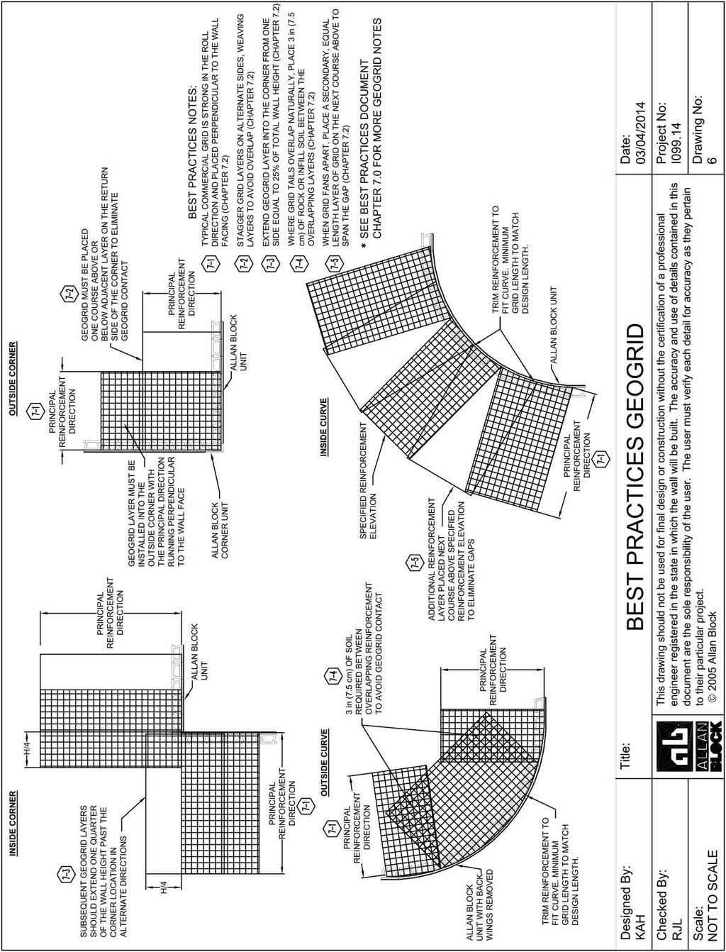
38 7.0 Geogrid Reinforcement Best Practices for Allan Block Segmental 7.1) Certification to ensure proper materials for the geogrid reinforcement. Most geogrids used for soil reinforcement are manufactured from polyester fiber. To ensure a high quality product, use a geosynthetic reinforcement that has obtained an NTPEP Report. a) There are many different international manufacturers that are supplying geogrid reinforcement, and they are not all equal. It is important to understand what influences the durability of the geogrid and the U.S. Federal Highway Administration identified three key factors: i) Soils that have a ph of 10 or more represent an environment that could potentially degrade the geogrid faster especially in the presence of sufficient water. ii) Polyester molecular weight the size of the polymer molecule has a significant influence on the chemical durability. iii) Polyester carboxyl end group (CEG) grids are less susceptible to degradation when they have fewer CEG in their molecular structure. b) Establish minimum requirements when using polyester geogrids. NCMA adopted the guidelines that the FHWA set for geogrid reinforcement. All polyester geogrids submitted for approval must be made of polyester fiber that meets the following specifications: i.) Molecular weight greater than 25,000 g/mol ii.) Caboxyl End Group less than 30 mmol/kg c) The certification, obtained from the geogrid manufacturer, must originate from the actual manufacturer of the fiber to show conformance with the specification. d) Designer must consider soils that have a ph of 10 or more represent an environment that could potentially degrade the geogrid faster especially in the presence of sufficient water and may require additional design criteria. 7.2) Proper orientation of grid and placement a) Typical commercial geogrid is strong in the roll direction and should be placed in sheets perpendicular to the wall facing. b) Utilize Section 2 Part 3.3 Geogrid Installation in the Allan Block Spec Book, page 4. i) Cut geogrid to designed embedment length and place on top of the Allan Block units to the back edge of the raised front lip or within 1 inch (2.5 cm) of the retaining wall face when using AB Fieldstone. ii) Extend away from wall approximately 3% above horizontal on compacted infill soils. c) For straight walls, placement of adjacent sheets of geogrid should be side-by-side without any overlap. For walls with corners or curves the following are the best practice method of placement: i) For outside corners, to avoid overlapping grid layers, grids should be stagger by one course on either side of the corner, weaving the strong direction from bottom to top of wall. See Allan Block standard detail 10 in Allan Block Spec Book, page 14. ii) For inside corner, extend the geogrid layer into the corner from one side a distance equal to 25% of the total wall height. Alternate extended geogrid layer from side to side per course to create a geogrid weave as wall is built. See Allan Block standard detail 9 in Allan Block Spec Book, page 14. Page 36
39 iii) For outside curves, where grid tails overlap naturally, place roughly 3 inch (7.5 cm) of wall rock or infill soil between the overlapping layers. See Allan Block standard detail 12 in Allan Block Spec Book, page 14. iv) For inside curves, where grid layers fan apart, place a secondary, equal length, layer of grid on the next course above the fanned gap. See Allan Block standard detail 11 in Allan Block Spec Book, page 14. Page 37
, depending on the application and the discretion of the wall design engineer.")
40 8.0 Tall Wall Considerations Best Practices for Allan Block Segmental 8.1) Tall Wall Considerations are to be employed with structures rising to a height of between feet (3 4.6 m), depending on the application and the discretion of the wall design engineer. A 10 foot (3 m) high wall structure with a slope or structure above would be considered as a tall wall, while the same wall height constructed with a level condition above the wall without any additional surcharge may not require consideration as a tall wall. Several factors may change a typical design when structures reach these defined higher levels such as the depth of wall rock, increased design parameters, enhanced structural fill and global stability analysis requirements. 8.2) Wall rock depth behind the block and material used. a) Site conditions and wall height should make Figure 8-1: Variable Wall Rock Thickness the engineer consider expanding the depth and or size of material used. b) Typical wall rock depth will vary with wall height, if select/structural fill is not utilized in the reinforced mass, Figure 8-1. i) For walls up to 15 feet (4.6 m) tall, 12 inch (30 cm) typical depth top to bottom. ii) For walls from 15 to 25 feet (4.6 m 7.6 m) tall, the bottom half is 24 inch (60 cm) deep and the top half is 12 inch (30 cm) deep. iii) For walls over 25 feet (7.6 m) tall, the bottom half is 36 inch (90 cm) deep and the top half is divided in two with a 24 inch (60 cm) deep column and a 12 inch (30 cm) deep column at the top. 8.3) For tall walls the engineer should increase design parameters of compaction and wall rock usage. a) Select/structural fill should be specified for the bottom 1/3 to 1/2 of the reinforced fill. The use of additional select/structural fill should extend to the entire length of the reinforcement. This fill material should have a PI of less than 6 for walls up to 20 feet (6.1 m) and for taller walls the material should have a PI of zero. An example of what type of fill should be considered for this area would be compactable sands or gravels. b) The engineer must carefully review the site geometry and structures above and below the wall to adequately plan for the use of the land placed into service by the retaining wall structure. Page 38
41 c) Provide detailed requirements for onsite inspection to ensure that detailed specifications are complied with during construction. This includes, but is not limited to: i) Confirmation of the foundation soils ii) Confirmation of the retained soils iii) Verify the imported materials iv) Confirm reinforcement material v) Verify the block vi) Validate soil placement and compaction. (1) A single test/confirmation for each of the items listed would not be considered adequate. A detailed construction log should be used with sign offs at incremental levels by the responsible parties. d) Consider how much potential settlement will impact structures above the reinforced soil mass. Consider increasing compaction requirements from 95 percent of standard proctor to 98% to minimize settlement where essential to the application. e) A detailed review and implementation of a water management plan is essential. This should include a detailed drawing for water collection and water flow diagrams for both above and below grade drainage. Below grade utilities and above grade structures should be included in the overall site design to ensure that site details such as storm drains and curb and gutters do not influence the overall wall envelope or effect performance. Unless designed to accommodate hydrostatic loading, it is essential that the reinforced soil mass not be exposed to outside water sources that would rise above the level of incidental water. f) As walls get taller the internal stresses increase and depending on the soils used, can cause lateral loads pushing on the back of the facing. To minimize internal lateral loads on the Allan Block facing, it is recommended to utilize the described soils above and to expand the depth of the wall rock column behind the facing, See Section 8.2.b for more information. Expanding the wall rock zone behind the wall also reduces down drag forces on the geogrid caused by localized settlement and allows for easier compaction directly behind the block. 8.4) As walls increase in height the active earth forces also increase in the lower portion of the wall. Therefore it is not uncommon in taller walls to increase the strength of the lower geogrid layers or decrease the grid spacing to accommodate the higher design forces. 8.5) The overall global stability of tall walls must be considered separately from the standard wall design to ensure the stability of the entire project site. For more information on global stability see Chapter 9.0 Global Stability - General and Chapter 10.0 Global Stability - Terraced. 8.6) Internal Compound Stability (ICS) calculations provide insight into potential global or overall stability issues. When more than 50% of the slip arcs originate at the back of the design envelope, as defined in Chapter 1, Section 1.7 b, a full global/overall stability analysis should be recommended to the owner by the owner s geotechnical engineer. Page 39
 Wall embedment depth should be determined by the wall design engineer based on typical industry standard and specific site requirements.")
42 9.0 Global Stability General Best Practices for Allan Block Segmental 9.1) Wall embedment depth should be determined by the wall design engineer based on typical industry standard and specific site requirements. a) Walls with slopes below must have additional buried course for stability. For walls with slopes below, local ordinances commonly reference to bury enough blocks to have a 5 ft to 7 ft (1.5 m to 2.1 m) level bench in front of the wall, and then the 1 inch (2.5 cm) of depth per 1.0 ft (30 cm) of wall height rule is used beyond that point, Figure 9-1. After the wall is complete, Figure 9-1: Toe Slope Embedment the level area can be backfilled to continue the appearance of a continuous slope. b) In general when a slope below the wall is present, there is need for a global stability analysis to confirm the overall stability of the site. 9.2) If a global stability analysis is not included in the wall designer's scope of work, establish that when a global stability analysis is required by the wall designer, using their best engineering judgment, then the owner will contract with a geotechnical engineer for overall site stability. Global stability analysis should be run for a variety of conditions including: a) For those walls with slopes below or above. b) Walls built in sites with clays, silts, poorly graded sands, expansive clays and/or soils with a PI greater than 20 and or a LL greater than 40. i) The infill soil used must meet or exceed the designed friction angle and description noted on the design cross sections, and must be free of debris and consist of one of the following inorganic USCS soil types: GP, GW, SW, SP, GP-GM or SP-SM meeting the following gradation as determined in accordance with ASTM D422. Sieve Size Percent Passing 1 in (25 mm) No. 4 (4.75 mm) No. 40 (0.425 mm) 0-60 No. 200 (0.075 mm) 0-35 c) For walls where more than 50% of the Internal Compound Stability (ICS) slip arcs fall at the back of the wall design envelope when ICS is run in AB Walls 10. We have identified a Design Envelope for the wall designer that defines the extents of an ICS evaluation within that envelope. An ICS analysis does not take into account a slope below the wall, as the bottom slip arc is located at the base of the bottom block. Therefore it will not provide guidance for what happens below the wall. One easy to identify guide for additional global evaluation may be found by reviewing where the ICS slip arcs with the minimum factors of safety originate. When a concentration of ICS slip arcs originate at the back of the Design Envelope, a complete global stability analysis should be conducted, See Figure 9-2. Page 40
 For walls with global stability concerns, it is common to increase the stability by: a) Increasing the length of the geogrid layers to force the minimum slip arcs deeper into the hillside.")
43 Figure 9-2: Design Envelope ICS 9.3) For walls with global stability concerns, it is common to increase the stability by: a) Increasing the length of the geogrid layers to force the minimum slip arcs deeper into the hillside. b) Increasing the depth of buried block to force the minimum slip arcs deeper into the hillside. c) Increasing the strength of the geosynthetic reinforcement layers to force the minimum slip arcs deeper into the hillside. d) Increasing the friction angle of the infill soil will increase the soil s shear resistance which will increase stability. e) If the cause for the global stability problems is weak foundations soils, it may be necessary for the geotechnical engineer on the project to do foundation improvements before the retaining walls are built. Page 41
44 10.0 Global Stability Terraced Walls 10.1) Whenever walls are constructed in a terraced arrangement, or any of the other conditions listed, the designer must consider the overall global stability of the structure. a) It is common to have the design grid lengths for the bottom terrace equal to at least 60% of the total terraced structure height. b) Subsequent terraces above would use similar rationale to determine their minimum grid lengths. c) When determining the surcharge applied from the upper wall onto the lower wall, it is common to consider the walls as independent if they are spaced apart a minimum of twice the height of the lower wall. If they are spaced closer, the lower wall must be designed to carry the surcharge of the upper wall(s), Figure Figure 10-1: Terraced Wall Applications d) These recommendations do not eliminate the need to consider a global stability analysis. e) Greater attention to compaction should be placed on the foundation soils below the upper terraces and in transition areas where the wall splits from one wall into two. i) If the soils are not properly compacted in these areas, settlement can occur over time that could cause aesthetic concerns. Page 42
45 11.0 Seismic Considerations Best Practices for Allan Block Segmental 11.1) For walls with dynamic loading: a) Designer must understand the local seismic code requirements before starting design. b) Closer spacing of geogrid is recommended, maximum 16 inch (40 cm). c) Extension of the top layers of geogrid. Typically the top layers will be extended to roughly 90% or more of the wall height to satisfy design requirements. d) Using select/structural backfill will reduce the effects of the dynamic loading. e) For more information on seismic design and the effects on segmental retaining walls, see the Allan Block Executive Summary of the independent full-scale seismic testing conducted by Columbia University and the National Research Institute of Japan. 11.2) When dealing with a slope above a wall with seismic loading applied to the wall, the same acceleration coefficient applied to the wall must also be applied to the stability calculations of the slope. 11.3) The Mononobe-Okabe (M-O) seismic methodology places limits on the steepness of any slope above the wall. If during the design phase it is determined that the desired slope is not allowed, the site grading should be altered or the wall height should be increased to reduce the steepness of the slope above. See section 12.4 for description of slope steepness. 11.4) While the M-O method is the standard used in the seismic design of segmental retaining wall, a trail wedge method may be utilized to investigate walls when the M-O method becomes limited due to slopes above. Using methods similar to a global stability model the trial wedge method determines the weight of the soil wedge above the failure plan and determines the active earth pressure of the soil wedge acting at the back of the soil mass. Using the trial wedge method is not without limitations as well. The solution it provides is purely mathematical and understanding soil mechanics and the slope steepness limits is also important. The limitation to the steepness of a slope discussed in section 12.4 still apply, and if the designer chooses to utilize the trial wedge method for walk with slopes above that exceed the soil mechanic limits, they must review the slope stability in a global stability program and possibly reinforce the slope above the wall. For a greater discussion on the Trial wedge method see Chapter Five, Seismic Design, in the Allan Block Engineering Manual. Page 43
, whichever is greater, in seismically active areas or with any type of loading above the wall including slopes and surcharges.")
46 12.0 Above Wall Considerations Best Practices for Allan Block Segmental 12.1) Minimum grid lengths. a) Top layers of grid should be lengthened to 90% of wall height or an additional 3 ft (0.9 m), whichever is greater, in seismically active areas or with any type of loading above the wall including slopes and surcharges. In the event that an interference may exist with the top layer based on other structures in the reinforced zone it is acceptable to move this extended layer to a lower grid elevation at the top of the structure. b) The portion of wall above the top layer of geogrid should be reviewed as a gravity wall taking into account all soils and surcharge parameters. 12.2) Details for fencing and other potential lateral loads from objects located above or within the reinforced soil mass. a) Impact structures or fence posts should be positioned a minimum of 3 feet (0.9 m) from the back of top course to allow a properly designed load for local overturning. b) If fence posts must be placed within 3 ft (0.9 m) of the back of the wall facing, the designer must consider the localized top of wall overturning force into their design. c) Common lateral loads from railings are 50 lb/lf (0.74 kn/m) along the top of the railing or 200 lb (2.92 kn/m) point load at the top of the post or both depending on the local requirements. d) Common post footings are formed by using construction tubes placed at desired on-center locations during construction. If posts are placed after construction is complete, holes must be hand dug as using a power auger will cause severe damage to the geogrid layers. e) If the post design calls for an engineered product to solve localized overturning forces, a product such as the Sleeve-IT System can be specified. Sleeve-IT is a Stratagrid product designed for use in segmental retaining walls to resist top of wall overturning forces from fences and railing. For more information on design capacities and installation, contact Stratagrid at ) Details for placement and compaction of a slope above the wall structure. a) Proper lift and compaction recommendation should be followed from the geotechnical recommendations. See Chapter 6.0 Soils and Compaction. Page 44
47 12.4) Stability of slopes above the wall. a) There are limits to the steepness of a slope above a wall that must be considered when designing any soil structure. i) In static designs, the maximum unreinforced slope angle above any wall cannot exceed the friction angle of the soil used to reconstruct the slope. ii) In seismic designs, the maximum unreinforced slope angle above any wall cannot exceed the friction angle of the soil used to reconstruct the slope minus the seismic inertial angle. The seismic inertial angle is based on the horizontal and vertical seismic coefficients ( k h and k v ) determined by the soils engineer for that specific project site. If the desired slope above exceeds either of the two limits above, the designer must analyze the slope above in a global stability program and provide slope reinforcement as required. 12.5) Slopes above the wall must be compacted following the proper lift and compaction recommendation from the geotechnical recommendations. See chapter 6.0, Soils and Compaction. 12.6) Reinforcing the slope above the wall may be necessary to provide adequate stability to the wall system. Geogrid lengths typically matching the standard grid lengths in the wall along with their spacing are commonly used in walls with steep slopes above, greater than 3:1, and/or any slopes with poor soils or walls with seismic requirements. 12.7) Details for plantings located above the wall structure. a) In general, plantings in the reinforced zone are acceptable and may in fact enhance the reinforced soil mass provided: i) Engineer should review with the owner the planting plans from the landscape architect to verify size of root balls and if any geogrid layers will be disrupted. ii) Language can be placed in the project specifications. iii) Augers should never be used within the reinforced grid zone. iv) Consider the effect of excess irrigation. See Water Management, Chapter 3.0. Page 45
48 References Abramson, Lee W., Lee, Thomas S., Sharma, Sunil, Boyce, Glenn M., 2002, Slope Stability and Stabilization Methods, second edition, Wiley Publications, USA AISC Manual Committee, 1990, Manual of Steel Construction - Load and Resistance Factor Design, First Edition, 3rd Printing, American Institute of Steel Construction Inc. Allan Block Corp., 2010, AB Walls 10, Design Software for Segmental Retaining Walls, Allan Block, Bloomington, MN Allan Block Corp., 2010, Allan Block Engineering Manual, Allan Block, Bloomington, MN, USA Allan Block Corp., 2012, Allan Block Spec Book, A Comprehensive Guide and Design Details for Segmental Retaining Walls, Allan Block, Bloomington, MN, USA Allan Block Corp., 2014, Best Practices for SRW Walls, Allan Block, Bloomington, MN, USA Allan Block Corp., 2001, Commercial Installation Manual for Allan Block Retaining Walls, Allan Block, Bloomington, MN, USA American Association of State Highway and Transportation Officials (AASHTO) LRFD Bridge Design Specifications, 2012, Washington, D.C. ASTM C1372, Standard Specification for Dry-Cast Segmental Retaining Wall Units, American Society for Testing and Materials, West Conshohocken, Pennsylvania, USA ASTM C1262, Standard Test Method for Evaluating the Freeze-Thaw Durability of Dry-Cast Segmental Retaining Wall Units and Related Concrete Units, American Society for Testing and Materials, West Conshohocken, Pennsylvania, USA Carter, R. Lance and Bernardi, Michael, NCMA s Design Manual For Segmental Retaining Walls, Submittal requirements for polyester geogrid reinforcement, Geosynthetics, February 2014 Columbia University in Cooperation with Allan Block Corporation and Huesker Geosynthetics, 2003, Executive Summary - Seismic Testing - Geogrid Reinforced Soil Structures Faced with Segmental Retaining Wall Block, Allan Block, Bloomington, MN, USA Craig, R. F., 1992, Soil Mechanics, Fifth Edition, Chapman & Hall, London, ENGLAND Das, Braja M, 1994, Principles of Geotechnical Engineering,Third Edition, Chapter 10, PWS Pub Co., Boston, MA, USA Duncan, J Michael, Wright, Stephen G, 2005, Soil Strength and Slope Stability, Wiley Publications, USA Elias, Victor PE, Christopher, Barry, PhD and Berg, Ryan PE, 2001, Mechanically Stabilized Earth Walls and Reinforced Soil Slopes Design and Construction Guide Lines, FHWA NHI FHWA-HRT Composite Behavior of Geosynthetic Reinforced Soil Mass, July 2013 FHWA-HRT Geosynthetic Reinforced Soil Integrated Bridge System Interim Implementation Guide, June 2012 FHWA-HRT Geosynthetic Reinforced Soil Performance Testing Axial Load Deformation Relationships, August 2013 FHWA-RD Performance Test for Geosynthetic Reinforced Soil Including Effects of Preloading, June 2001 FHWA-HRT Sample Guide Specifications for Construction of Geosynthetic Reinforced Soil Integrated Bridge System (GRS-IBS), August 2012 Page 46
49 Kliethermes, J., K. Buttry, E. McCullough, and R. Wetzel. 1990, Modular Concrete Retaining Wall and Geogrid Performance and Laboratory Modeling, University of Wisconsin-Platteville, WI, USA Leshchinsky, D. and E.B. Perry, 1987, A Design Procedure for Geotextile Reinforced Walls, Geotechnical Fabrics Report. St. Paul: July/August Ling, Hoe I, et al, 2005, Large Scale Shaking Table Tests on Modular-Block Reinforced Soil Retaining Walls, Journal of the Geotechnical and Geoenvironmental Engineering, Vol. 131, No. 4, ASCE Ling, Hoe I, et al, 2012, Earthquake Response of Reinforced Segmental Retaining Walls Backfilled with Substantial Percentage of Fines, Journal of the Geotechnical and Geoenvironmental Engineering, ASCE McKittrick, D.P., 1978, Reinforced Earth: Application of Theory and Research to Practice, Reinforced Earth Technical Services, Report Arlington, VA: The Reinforced Earth Company Minnesota Department of Transportation, 1985, Walls, Section in Road Design Manual -- Part II., St. Paul, MN, USA National Concrete Masonry Associations, 2009, Design Manual for Segmental Retaining Walls, 3 rd Edition, NCMA, VA Peck, Ralph, edited by T.W. Lambe and R.V. Whitman, 1969, Earth Retaining Structures and Slopes, Chapter 13 in Soil Science, John Wiley & Sons, Inc. New York, NY, USA Sowers, G.B., and G.F. Sowers, 1970, Problems in Earth Pressure, Chapter 8 in Introductory Soil mechanics and Foundations, The Macmillan Company, New York, NY, USA Shiwakoti D.R., T.B,S, Pradhan and Leshchinsky D., 1998, Vol 5, No 6, Performance of Geosynthetic-Reinforces Soil Structures at Limit Equilibrium State Shukha, Robert, Baker, Rafael and Leshchinsky, Dov, 2005, Engineering Implications of the Relation between Static and Pseudo-Static Slope Stability Analysis, EJGE Paper Page 47

50 [Type text]
Specification Guidelines: Allan Block Modular Retaining Wall Systems
 Specification Guidelines: Allan Block Modular Retaining Wall Systems The following specifications provide Allan Block Corporation's typical requirements and recommendations. At the engineer of record's
SPECIFICATIONS FOR PRECAST MODULAR BLOCK RETAINING WALL SYSTEM (revised 5/8/7)
") Page 1 of 7 STONE STRONG SYSTEMS SPECIFICATIONS FOR PRECAST MODULAR BLOCK RETAINING WALL SYSTEM (revised 5/8/7) PART 1: GENERAL 1.01 Description A. Work includes furnishing and installing precast modular
Page 1 of 7 STONE STRONG SYSTEMS SPECIFICATIONS FOR PRECAST MODULAR BLOCK RETAINING WALL SYSTEM (revised 5/8/7) PART 1: GENERAL 1.01 Description A. Work includes furnishing and installing precast modular
ICC-ES Evaluation Report Issued July 1, 2011 This report is subject to renewal in one year.
 ICC-ES Evaluation Report ESR-1959 Issued July 1, 2011 This report is subject to renewal in one year. www.icc-es.org (800) 423-6587 (562) 699-0543 A Subsidiary of the International Code Council DIVISION:
SECTION SPECIFICATION FOR STONEBRIDGE RETAINING WALL SYSTEM
 SECTION 32 32 23 SPECIFICATION FOR STONEBRIDGE RETAINING WALL SYSTEM PART 1: GENERAL 1.01 Scope Work includes furnishing all materials, labor, equipment, and supervision to install a Stonebridge segmental
CONCRETE SEGMENTAL RETAINING WALL SYSTEM
 CONCRETE SEGMENTAL RETAINING WALL SYSTEM PART 1: GENERAL SPECIFICATIONS 1.01 Work Included A. Work shall consist of furnishing and constructing a Rockwood Classic 8, Classic 6 and Legend unit segmental
ENGINEERING DIRECTIVE
 Number: E-95-001 Date: 2/2/95 ENGINEERING DIRECTIVE Ross B. Dindio (Signature on Original) CHIEF ENGINEER The purpose of this engineering directive is to formally notify ALL Department engineering personnel
INSPECTION GUIDE FOR SEGMENTAL RETAINING WALLS TEK 18-11B
 An information series from the national authority on concrete masonry technology INSPECTION GUIDE FOR SEGMENTAL RETAINING WALLS TEK 18-11B Quality Assurance and Testing (2012) INTRODUCTION Segmental retaining
Segmental Retaining Walls Best Practices Guide. for the Specification, Design, Construction, and Inspection of SRW Systems
 Segmental Retaining Walls Best Practices Guide for the Specification, Design, Construction, and Inspection of SRW Systems Table of Contents Segmental Retaining Walls Best Practices Guide About NCMA 3 Acknowledgments
Section ( ) SPECIFICATION FOR SEGMENTAL CONCRETE UNIT RETAINING WALL
 SPECIFICATION FOR SEGMENTAL CONCRETE UNIT RETAINING WALL") Section 02834 (32 32 23) SPECIFICATION FOR SEGMENTAL CONCRETE UNIT RETAINING WALL PART 1: GENERAL 1.01 Description A. Work shall consist of furnishing and construction of a County Materials Retaining Wall
Section 02834 (32 32 23) SPECIFICATION FOR SEGMENTAL CONCRETE UNIT RETAINING WALL PART 1: GENERAL 1.01 Description A. Work shall consist of furnishing and construction of a County Materials Retaining Wall
LANDSCAPE RETAINING WALLS
 SUDAS Standard Specifications Division 9 - Site Work and Landscaping Section 9070 - Landscape Retaining Walls LANDSCAPE RETAINING WALLS PART - GENERAL.0 SECTION INCLUDES A. Modular Block Retaining Walls
MODULAR CONCRETE RETAINING WALL
 MODULAR CONCRETE RETAINING WALL PART 1: GENERAL 1.01 Description A. Work shall consist of furnishing and construction of a KEYSTONE Retaining Wall System or equal in accordance with these specifications
Section (02830) MODULAR CONCRETE RETAINING WALL
 MODULAR CONCRETE RETAINING WALL") Section 323223 (02830) MODULAR CONCRETE RETAINING WALL PART 1: GENERAL 1.01 Description A. Work shall consist of furnishing and constructing a VERDURA Retaining Wall System (or approved equal) in accordance
Section 323223 (02830) MODULAR CONCRETE RETAINING WALL PART 1: GENERAL 1.01 Description A. Work shall consist of furnishing and constructing a VERDURA Retaining Wall System (or approved equal) in accordance
SEGMENTAL BLOCK RETAINING WALLS. Comply with Division 1 - General Provisions and Covenants, as well as the following:
 SEGMENTAL BLOCK RETAINING WALLS PART 1 - GENERAL 1.01 SECTION INCLUDES Segmental Block Retaining Walls 1.02 DESCRIPTION OF WORK Constructing segmental block retaining walls. 1.03 SUBMITTALS Comply with
VERTI-BLOCK - DESIGN MANUAL
 Company Information General Information Verti-Block is the latest innovative forming system from Verti-Crete, LLC. Recognized worldwide for outstanding aesthetics and performance, Verti-Crete s proprietary
G R A V I T Y / G E O G R I D
 GRAVITY/GEOGRID MAGNUMSTONE Overview note: bolded terms are defined in our online glossary at www.cornerstonewallsolutions.com The MagnumStone retaining wall system was developed with the installer in
In preparation for constructing buildings on a property, the builder. Site Preparation CHAPTER
 CHAPTER 3 Site Preparation In preparation for constructing buildings on a property, the builder must consider a number of factors related to code requirements. The buildings must be located according to
Ohio Department of Transportation Division of Production Management Office of Geotechnical Engineering. Geotechnical Bulletin
 Ohio Department of Transportation Division of Production Management Office of Geotechnical Engineering Geotechnical Bulletin GB 2 SPECIAL BENCHING AND SIDEHILL EMBANKMENT FILLS Geotechnical Bulletin GB2
Anchorplex retaining wall construction guide. Building. Anchorplex. Retaining Wall Systems
 Anchorplex retaining wall construction guide Building Anchorplex Retaining Wall Systems Table of Contents and ow to Use This Guide table of contents ow to Use This Guide. 2 About the Anchorplex System.
Description. This work shall consist of furnishing materials and placement of modular block wall constructed in accordance with
 MODULAR CONCRETE BLOCK RETAINING WALL WITH GROUND REINFORCING The Standard Specifications are revised as follows: 732-R-310r 1of 11 Rev. 12-03-03 SECTION 105, AFTER LINE 48, INSERT AS FOLLOWS: When constructing
Wall Modular Block Mechanically Stabilized Earth, Item S.
 Wall Modular Block Mechanically Stabilized Earth, Item 532.0300.S. A Description (1) This special provision describes designing, furnishing materials and erecting a permanent earth retention system in
Redi Rock Specification and Installation Manual
 Redi Rock Specification and Installation Manual 1.0 General Scope This Specification covers the Design, Materials and Installation of Redi Rock modular block Retaining and Freestanding Wall systems as
Design Manual: Gravity Wall. Section 1
 Design Manual: Gravity Wall Section 1 A Design Manual: Gravity Wall General Information Company Information Verti-Block is the latest innovative forming system from Verti-Crete, LLC. Recognized worldwide
Retaining Wall Systems
 Retaining Wall Systems A family of Retaining Wall Products The versatile Allan Block product line allows easy design and construction of retaining walls to meet specific engineering and site requirements.
SECTION EXCAVATION AND EMBANKMENT. B. Subbase Grading A samples for gradation analysis.
 PART 1 GENERAL 1.1 DESCRIPTION A. The WORK under this Section includes providing all labor, materials, tools and equipment necessary for excavation and embankment construction to the lines, grades and
DESIGN CONSIDERATIONS FOR NSWS NATURAL STONE RETAINING AND FREE-STANDING WALL SYSTEMS
 DESIGN CONSIDERATIONS FOR NSWS NATURAL STONE RETAINING AND FREE-STANDING WALL SYSTEMS Natural Stone Wall Solutions, Inc (NSWS ) 2352 Main Street, Suite 103 Concord, MA 01742 (978) 461-1777 Concept and
AUGUST 2017 HASTINGS. retaining walls installation guide
 AUGUST 2017 HASTINGS retaining walls installation guide RETAINING WALL INSTALLATION GUIDE RETAINING WALL information Austral Masonry retaining wall blocks are an ideal choice for retaining walls in gardens,
SECTION PERMEABLE INTERLOCKING CONCRETE UNIT PAVEMENT
 SECTION 32 14 13 19 PERMEABLE INTERLOCKING CONCRETE UNIT PAVEMENT SECTION 32 14 13 19 PERMEABLE INTERLOCKING CONCRETE UNIT PAVEMENT PART 1 - GENERAL 1.1 SUMMARY A. Section Includes: 1. Permeable Articulating
DIVISION: EXTERIOR IMPROVEMENTS SECTION: RETAINING WALLS SECTION: SEGMENTAL RETAINING WALLS REPORT HOLDER:
 0 Most Widely Accepted and Trusted ICC ES Evaluation Report ICC ES 000 (800) 423 6587 (562) 699 0543 www.icc es.org ESR 3073 Reissued 07/2017 This report is subject to renewal 07/2018. DIVISION: 32 00
MECHANICALLY STABILIZED EARTH (MSE) WALL SYSTEMS
 WALL SYSTEMS") DRAINAGE SOLUTIONS SINCE 1908 MECHANICALLY STABILIZED EARTH (MSE) WALL SYSTEMS PERMANENT AND TEMPORARY ENGINEERED WALL SOLUTIONS ECONOMICAL DURABLE VERSATILE ARMTEC.COM MSE RETAINING WALLS Armtec Mechanically
DRAINAGE SOLUTIONS SINCE 1908 MECHANICALLY STABILIZED EARTH (MSE) WALL SYSTEMS PERMANENT AND TEMPORARY ENGINEERED WALL SOLUTIONS ECONOMICAL DURABLE VERSATILE ARMTEC.COM MSE RETAINING WALLS Armtec Mechanically
Tasman Retaining Wall System
 Tasman Retaining Wall System The Tasman Retaining Wall System incorporates purpose made corners and capping units to provide classical reconstructed stone retaining walls for any landscape situation. From
DESIGNING AND CONSTRUCTION OF T-WALL RETAINING WALL SYSTEM
 Istanbul Bridge Conference August 11-13, 2014 Istanbul, Turkey DESIGNING AND CONSTRUCTION OF T-WALL RETAINING WALL SYSTEM T. C. NEEL and K.BOZKURT ABSTRACT This work shall consist of the design, manufacture
NOVEMBER 2016 MAGNUMSTONE. retaining walls installation manual
 NOVEMBER 2016 MAGNUMSTONE retaining walls installation manual AUSTRAL MASONRY CONTENTS Magnumstone Installation Guide 04 Overview 07 Unit Specifications 08 Installation 08 Gravity MagnumStone Wall 16 Geogrid
STANDARD SPECIFICATION FOR CRIBLOCK CONCRETE CRIBWALL
 STANDARD SPECIFICATION FOR CRIBLOCK CONCRETE CRIBWALL 1. SCOPE 2. DESIGN 3. MATERIALS 4. CONSTRUCTION 5. METHOD OF MEASUREMENT AND PAYMENT SCOPE This Specification sets out requirements for the design,
Trusted ICC ES. Conformity! Evaluation. ICC-ES Evaluation
 0 Most Widely Accepted and Trusted ICC ES Evaluation Report ICC ES 000 (800) 423 6587 (562) 699 0543 www.icc es.orgg ESR 2113 Reissued 08/2017 This report is subject to renewal 08/2019. DIVISION: 32 00
Tasman Retaining Wall
 Tasman Retaining Wall EVALUATION AND INSTALLATION GUIDE Landscaping Tasman Retaining Wall Evaluation and Installation Guide This installation guide demonstrates the basics on how to construct: A. Tasman
PERMEABLE INTERLOCKING PAVERS
 PERMEABLE INTERLOCKING PAVERS PART 1 - GENERAL 1.01 SECTION INCLUDES A. Subgrade Preparation B. Placement of Storage Aggregate C. Placement of Filter Aggregate D. Placement of Bedding Course E. Placement
GEOSYTHETIC SLOPE SPEC-V0704rev.doc STANDARD SPECIAL PROVISION FOR GEOSYNTHETIC REINFORCED SLOPE CONSTRUCTION
 GEOSYTHETIC SLOPE SPEC-V0704rev.doc STANDARD SPECIAL PROVISION FOR GEOSYNTHETIC REINFORCED SLOPE CONSTRUCTION I. DESCRIPTION - This work consists of furnishing the required materials and construction of
Mechanically Stabilized Earth Structures By Blaise J. Fitzpatrick, P.E. Fitzpatrick Engineering Associates, P.C.
 Mechanically Stabilized Earth Structures By Blaise J. Fitzpatrick, P.E. Fitzpatrick Engineering Associates, P.C. I. History or MSE Structures II. Industry Design Methods and Programs III. Products and
Construction Procedures
 Construction Procedures 2014 Rev. 1.6 1 Introduction This manual presents the methods and procedures necessary for the proper erection of a LOCK+LOAD retaining wall. problems later during the service life
Soils Information Retained soils, foundation soils, reinforced soils, etc. Project Specification Design and project information and requirements.
 Retaining Walls ReCon retaining walls are classified as Precast Modular Block Walls or PMBWs. When designing a PMBW, it is critical that all of the appropriate information be gathered so that a proper
SPECIFICATION FOR REINFORCED SOIL WALL
 SPECIFICATION FOR REINFORCED SOIL WALL 1.0 EXTENT OF WORK The work shall consist of Reinforced Soil walls built in accordance with this specification and in conformity with the lines, levels and details
02632 Segmental Concrete Retaining Wall System Page - 1
 02632 Segmental Concrete Retaining Wall System Page - 1 (Last Revised 8/23/13) 02632 SEGMENTAL CONCRETE RETAINING WALL SYSTEM SELECTED LINKS TO SECTIONS WITHIN THIS SPECIFICATION Part 1 General Clean Up
Uwall UNIVERSAL CONSTRUCTION MANUAL
 Uwall UNIVERSAL Retaining Wall System CONSTRUCTION MANUAL TM President s Letter CSI is a leader in its industry supplying precast infrastructure products throughout New England and beyond since 1972, developing
STATE OF OHIO DEPARTMENT OF TRANSPORTATION SUPPLEMENTAL SPECIFICATION 863 REINFORCED SOIL SLOPES. October 19, 2012
 STATE OF OHIO DEPARTMENT OF TRANSPORTATION 863.01 Description 863.02 Materials 863.03 Construction 863.04 Method of Measurement 863.05 Basis of Payment SUPPLEMENTAL SPECIFICATION 863 REINFORCED SOIL SLOPES
SPECIFICATION FOR PIPE CULVERT CONSTRUCTION
 SPECIFICATION FOR PIPE CULVERT CONSTRUCTION 1. SCOPE Pipe culverts shall be constructed in accordance with this specification and in conformity with the lines, levels and cross-sections shown on the drawings.
2.1 Backfill - General
 2.1 Backfill - General Excavations are made for the purpose of constructing bridge substructure elements, and consequently requiring competent backfill material. The backfill material must be adequately
BIO-AQUIFER STORM SYSTEM
 BIO-AQUIFER STORM SYSTEM Specifications for Construction PART 1 GENERAL 1.01 SECTION INCLUDES A. Providing labor, materials, tools and equipment to furnish and install a permeable concrete paving stone
C. Foundation stabilization for pipe and utility structures.
 PART 1 - GENERAL 1.1 SECTION INCLUDES A. Excavating, backfilling, and compacting for utilities, including pipe, structures, and appurtenances. B. Control of water in trenches. C. Foundation stabilization
R-TANK SPECIFICATIONS
 TECHNICAL STORMWATER MANAGEMENT R-TANK SPECIFICATIONS PART 1 GENERAL 1.01 Related Documents A. Drawings, technical specification and general provisions of the Contract as modified herein apply to this
ODOT Design & Construction Requirements for MSE Walls
 ODOT Design & Construction Requirements for MSE Walls Peter Narsavage, P.E. Foundation Engineering Coordinator Ohio Department of Transportation Office of Structural Engineering 2006 Ohio Transportation
B. Subsurface data is available from the Owner. Contractor is urged to carefully analyze the site conditions.
 SECTION 31 23 33 - TRENCHING, BACKFILLING AND COMPACTION PART 1 - GENERAL 1.1 SCOPE A. This Section specifies the requirements for excavating and backfilling for storm sewer, sanitary sewer, water distribution
SECTION AGGREGATES
 SECTION 32 05 00 AGGREGATES PART 1 GENERAL 1.01 SUMMARY A. Section Includes: 1. Aggregate base 2. Engineered fill 3. Backfill 4. Fine filter aggregate (non-frost susceptible fill) 5. Riprap 6. Recreational
Construction Inspection Checklists
 III. Construction Inspection Checklists 33 Bioretention - Construction Inspection Checklist Project: Location: Site Status: Date: Time: Inspector: Construction Sequence Satisfactory / Unsatisfactory Comments
How To Install Your Cambridge Pavingstones System How To Install Your Cambridge Segmental Retaining Wall System
 4 How To Install Your Cambridge Pavingstones System Step 1. Preparation: Sketch a diagram of area to be paved. Square off a 90-degree corner. Set stakes for outside perimeters 6 inches away from area.
Tasman and Norfolk Retaining Wall
 Tasman and Norfolk Retaining Wall Evaluation and Installation Guide BAINES We deliver Sydney s Best! Order online: bcsands.com.au Call: (02) 8543 3400 Taren Point & Mascot Tasman and Norfolk are registered
SECTION TRENCHING & BACKFILLING
 SECTION 02225 - TRENCHING & BACKFILLING 1.0 GENERAL 1.1 Work included in this Section includes trenching and backfilling for underground pipelines and related structures only. 1.2 Reference Specifications
MOA Project # Golden View Drive Intersection & Safety Upgrades
 Appropriate transitions can include extending the insulation beyond the roadway improvements, reducing the insulation thickness, or angling the insulation downward. Use of a frost tolerant section, an
SEGMENTAL RETAINING WALL CONSTRUCTION
 SRW HISTORY ARTICLE SERIES This is the seventh article in a series of ten articles on the history of segmental retaining walls developed under a grant from the NCMA Education and Research Foundation. Figure
4.8. Subsurface Infiltration
 4.8. Subsurface Infiltration Subsurface infiltration systems are designed to provide temporary below grade storage infiltration of stormwater as it infiltrates into the ground. Dry wells, infiltration
INDEX FOR SPECIFICATIONS FOR REMOVING CULVERTS AND PLACING CULVERTS SCOPE... 1
 March 2002 No. 400 INDEX FOR SPECIFICATIONS FOR REMOVING CULVERTS AND PLACING CULVERTS 400. 1 SCOPE... 1 400. 2 REMOVING CULVERTS AND TIMBER STRUCTURES 2.1 Concrete and Metal Pipe Culverts... 1 2.2 Structural
4.8. Subsurface Infiltration
 4.8. Subsurface Infiltration Subsurface infiltration systems are designed to provide temporary below grade storage infiltration of storm water as it infiltrates into the ground. Dry wells, infiltration
CONSTRUCTION SURVEY. Construction survey includes personnel, equipment, and supplies required for, but not limited to, the following:
 CONSTRUCTION SURVEY PART 1 - GENERAL 1.01 SECTION INCLUDES Construction survey includes personnel, equipment, and supplies required for, but not limited to, the following: A. Construction Survey: 1. Project
cambridgewallsupport.com cambridgepavers.com
 cambridgewallsupport.com cambridgepavers.com INDEX Inside This Guide Page Introduction to Sigma Wall Systems 3 Sigma Stones 4 Building a Wall 6 Foundation 7 Installation 9 Projects 19 Installing Sigma
SECTION STORM DRAINAGE AND STORMWATER MANAGEMENT
 SECTION 322 - STORM DRAINAGE AND STORMWATER MANAGEMENT 322.01 DESCRIPTION Work includes all labor, material and equipment to construct storm drain systems and stormwater management facilities, including
Design Parameters. Wall Geometry. Soils Information
 Wall Geometry When planning a ReCon retaining wall, the most logical place to start is the wall location and where it resides with reference to the project site and topography. For most commercial projects
ITEM D-701 PIPE FOR STORM DRAINS AND CULVERTS
 ITEM D-701 PIPE FOR STORM DRAINS AND CULVERTS 701-1 DESCRIPTION 701-1.1 This item shall consist of the construction of pipe culverts, and storm drains, removal of existing storm pipes, connections to existing
HOW TO BUILD Garden Walls Frestanding & Landscape Walls
 HOW TO BUILD Garden Walls Frestanding & Landscape Walls 10 Cambridge Wall Book Garden walls This layout depicts a common application of landscape and freestanding designs together in one wall with Columns
Steps And Stairs Installation Option 1 - Steps In Wall Option 2 - Steps With Plant Space Option 3 - Steps In Front of Walls Option 4 - Steps Along
 Steps And Stairs Installation Option 1 - Steps In Wall Option 2 - Steps With Plant Space Option 3 - Steps In Front of Walls Option 4 - Steps Along Wall Face Option 5 - Steps In Wall; 10 (25cm) Tread Option
SPECIFICATIONS FOR BRIDGE CONSTRUCTION SECTION 2 BACKFILL. 2.1 General...2-1
 SPECIFICATIONS FOR BRIDGE CONSTRUCTION SECTION 2 BACKFILL TABLE OF CONTENTS 2.1 General...2-1 2.2 Materials...2-1 2.2.1 Compacted Non-granular Material...2-1 2.2.2 Gravel Material and Crushed Aggregate
A.2.a Random Riprap... Table
 3601 RIPRAP MATERIAL 3601.1 SCOPE Provide stone and filter layer material for use in random or hand-placed riprap, gabion, and revet mattress construction. 3601.2 REQUIREMENTS A Stones A.1 Quality Provide
CITY OF LETHBRIDGE SECTION Construction Specifications SIDEWALK CONSTRUCTION PAGE 1 of 5
 Construction Specifications SIDEWALK CONSTRUCTION PAGE 1 of 5 1.0 EXCAVATION AND FILL 1.1 GENERAL.1 The excavation or fill shall be made to provide proper grade, lines and crosssection for the laying of
HYDROGRID SUBSURFACE IRRIGATED HARTRU TENNIS COURTS
 HYDROGRID SUBSURFACE IRRIGATED HARTRU TENNIS COURTS PART 1 - GENERAL WORK INCLUDED A. Provide all equipment and materials, and do all work necessary to construct a HydroGrid subsurface irrigated fastdry
Design Data 6. Loads and Supporting Strengths Elliptical and Arch Pipe. Values of B d
 Design Data 6 Loads and Supporting Strengths Elliptical and Arch Pipe The hydraulic and structural characteristics of elliptical and arch shapes offer advantages, under certain conditions, over the circular
SECTION RIPRAP, BOULDERS, AND BEDDING
 SECTION 31 37 00 RIPRAP, BOULDERS, AND BEDDING PART 1 GENERAL 1.01 SECTION INCLUDES A. The WORK includes excavation, grading, and installation of riprap, boulders, soil riprap, void-filled riprap, and
Bureau of Materials Materials Approval Procedures
 Bureau of Materials Materials Approval Procedures MAP Number: 116-15 Effective Date: April 1, 2015 Approved By: Eileen Sheehy PROCEDURE FOR APPROVAL OF MECHANICALLY STABILIZED EARTH (MSE) RETAINING WALL
SECTION 19 - TRENCH EXCAVATION, BEDDING AND BACKFILL TABLE OF CONTENTS
 SECTION 19 - TRENCH EXCAVATION, BEDDING AND BACKFILL TABLE OF CONTENTS Section Page 19-1 TRENCH EXCAVATION...19.1 19-1.01 Exploratory Excavation...19.1 19-1.02 Trench Width...19.1 19-1.02.A Storm Drain
SECTION 19 - TRENCH EXCAVATION, BEDDING AND BACKFILL TABLE OF CONTENTS
 SECTION 19 - TRENCH EXCAVATION, BEDDING AND BACKFILL TABLE OF CONTENTS Section Page 19-1 TRENCH EXCAVATION... 19-1 19-1.01 Exploratory Excavation... 19-1 19-1.02 Trench... 19-1 19-1.02.AStorm Drain Pipe...
MSE WALLS CASE STUDIES. by John G. Delphia, P.E. TxDOT Bridge Division Geotechnical Branch
 MSE WALLS CASE STUDIES by John G. Delphia, P.E. TxDOT Bridge Division Geotechnical Branch COMMON RETAINING WALL TYPES CONCRETE BLOCK MSE TEMPORARY EARTH SPREAD FOOTING Gabions Drilled Shaft Soil Nail Tiedback
Steps And Stairs Installation Steps In Wall - Option 1 Steps In Front of Walls - Option 2 Steps In Wall; 10 (25cm) Tread - Option 3 Step Parallel to
 Tread - Option 3 Step Parallel to") Steps And Stairs Installation Steps In Wall - Option 1 Steps In Front of Walls - Option 2 Steps In Wall; 10 (25cm) Tread - Option 3 Step Parallel to Wall - Option 4 Steps and Stairs Q & A E CONSTRUCTION
Steps And Stairs Installation Steps In Wall - Option 1 Steps In Front of Walls - Option 2 Steps In Wall; 10 (25cm) Tread - Option 3 Step Parallel to Wall - Option 4 Steps and Stairs Q & A E CONSTRUCTION
Contact the Jurisdictional Engineer for materials allowed by each jurisdiction.
 Design Manual Chapter 3 - Sanitary Sewers 3C - Facility Design 3C-1 Facility Design A. Capacity of Pipe Pipe sizes 15 inches and smaller should carry the peak flow at a depth of no more than 0.67 of the
SECTION EXCAVATION AND BACKFILL FOR UTILITIES AND STRUCTURES
 SECTION 02215 EXCAVATION AND BACKFILL FOR UTILITIES AND STRUCTURES PART 1 - GENERAL 1.1 DESCRIPTION: This section includes materials, testing, and installation of earthwork for excavations, fills, and
STORMCAPTURE. Installation Manual
 STORMCAPTURE Installation Manual Introduction Site Preparation Delivery & Installation LinkSlabs Backfill Introduction StormCapture (shown in Figure 1) is a total stormwater management system. The highly-configurable
SECTION 19 - TRENCH EXCAVATION, BEDDING AND BACKFILL TABLE OF CONTENTS
 SECTION 19 - TRENCH EXCAVATION, BEDDING AND BACKFILL TABLE OF CONTENTS Section Page 19-1 TRENCH EXCAVATION... 19.1 19-1.01 Exploratory Excavation... 19.1 19-1.02 Trench Width... 19.1 19-1.02.A Storm Drain
Highway Drainage 1- Storm Frequency and Runoff 1.1- Runoff Determination
 Highway Drainage Proper drainage is a very important consideration in design of a highway. Inadequate drainage facilities can lead to premature deterioration of the highway and the development of adverse
Geoguide 6 The New Guide to Reinforced Fill Structure and Slope Design in Hong Kong
 Geoguide 6 The New Guide to Reinforced Fill Structure and Slope Design in Hong Kong Geotechnical Engineering Office Civil Engineering Department The Government of the Hong Kong Special Administrative Region
DIVISION 31 EARTHWORK 2006 Edition, Published January 1, 2006; Division Revision Date: January 31, 2012
 2006 Edition, Published January 1, 2006; Division Revision Date: January 31, 2012 PART FIVE DOCUMENTS FOR SITE AND INFRASTRUCTURE 31 00 00. EARTHWORK 31 10 00. SITE CLEARING.1 STRUCTURE REMOVAL: Include
Design and Installation Guidelines for Retaining Walls. 1 P age. Geo Products, LLC 8615 Golden Spike Lane Houston, TX Phone:
 Design and Installation Guidelines for Retaining Walls 1 P age Geo Products, LLC 8615 Golden Spike Lane Houston, TX 77086 Phone: 281.820.5493 2011 Geo Products, Fax: 281.820.5499 LLC www.geoproducts.org
SECTION INTERLOCKING PRECAST CONCRETE UNIT PAVERS
 SECTION 321413.13 INTERLOCKING PRECAST CONCRETE UNIT PAVERS PART 1 - GENERAL 1.1 SUMMARY A. This Section includes the following: 1. Interlocking concrete paver units. 2. Sand setting bed. 3. Sand joint
INDEX FOR SPECIFICATIONS FOR JACKING CULVERTS THROUGH EMBANKMENTS SCOPE... 2
 INDEX FOR SPECIFICATIONS FOR JACKING CULVERTS THROUGH EMBANKMENTS 410. 1 SCOPE... 2 410. 2 DEFINITIONS 2.1 Tunneling and Jacking... 2 2.2 Tunneling... 2 2.3 Jacking... 2 410. 3 MATERIALS 3.1 General...
SECTION 1100 GRADING 1102 MATERIALS AND DEFINITIONS.
 SECTION 1100 GRADING 1101 SCOPE. This section covers the performance of all work required for grading the project in coordination with all previous work performed at the locations shown on the contract
File No Supplemental November Geotechnical and Environmental Consulting Engineers
 Supplemental Information & Geotechnical Recommendations Proposed New Solar Valley Location B (East of Building No. 7) Cañada Community College 4200 Farm Hill Boulevard Submitted to: Mr. Peter Hempel Construction
DETERMINATION OF THE LONG-TERM PROPERTIES FOR MIRAGRID XT GEOGRIDS
 DETERMINATION OF THE LONG-TERM PROPERTIES FOR MIRAGRID XT GEOGRIDS Prepared by: TenCate Geosynthetics Americas 365 South Holland Drive Pendergrass, GA 30567 Tel 706 693 2226 Fax 706 693 4400 www.tencate.com
BITUMEN-SET PRECAST CONCRETE PAVING SLABS
 SECTION 32 14 13.16 BITUMEN-SET PRECAST CONCRETE PAVING SLABS (1995 MasterFormat Section 02784) NOTE: This guide specification is the U.S. for concrete paving slabs adhered with a neoprene mastic to a
COMPACTED CLAY LINERS
 Technical Reference Document for Liquid Manure Storage Structures COMPACTED CLAY LINERS Table of Contents SECTION 1 - PURPOSE AND SCOPE 1.1. Purpose of the Technical Reference Document 1.2. Requirement
of GENERAL. A. Description
 02920-1 of 11 SECTION 02920: EARTH TUNNELING 02920.01 GENERAL A. Description Earth tunneling shall include, but not necessarily be limited to, constructing earth tunnels and furnishing and installing tunnel
DESIGN & INSTALLATION GUIDELINES STANDARD PREMIUM RETAINING WALLS FOR GOVERNMENTAL, COMMERCIAL, AND RESIDENTIAL APPLICATIONS.
 DESIGN & INSTALLATION GUIDELINES STANDARD PREMIUM RETAINING WALLS FOR GOVERNMENTAL, COMMERCIAL, AND RESIDENTIAL APPLICATIONS. TABLE OF CONTENTS 1 Introduction & Unit Specifications...5 2 System Overview...7
DETERMINATION OF THE LONG TERM PROPERTIES FOR MIRAFI PET-SERIES REINFORCEMENT GEOTEXTILES BY GRI-GT7 AND NCMA GUIDELINES
 DETERMINATION OF THE LONG TERM PROPERTIES FOR MIRAFI PET-SERIES REINFORCEMENT GEOTEXTILES BY GRI-GT7 AND NCMA GUIDELINES Prepared by: TenCate TM Geosynthetics North America 365 South Holland Drive Pendergrass,
SECTION EXCAVATING, BACKFILLING, AND COMPACTION FOR UTILITIES
 SECTION 02221 EXCAVATING, BACKFILLING, AND COMPACTION FOR UTILITIES PART 1 GENERAL 1.01 SUMMARY A. Related Sections: 1. 02200 - Earthwork. 2. 02660 - Water Systems. 3. 02720 - Storm Drainage System. 4.