Wind-induced Pressures on Patio Covers
|
|
|
- Rhoda Hampton
- 5 years ago
- Views:
Transcription
1 Wind-induced Pressures on Patio Covers by Ioannis Zisis 1 and Ted Stathopoulos 2, F.ASCE CE Database Keywords: wind tunnel tests, wind loads, low-rise buildings, load distribution standards and codes. Abstract A wind tunnel study has been carried out to assess wind loads on patio covers attached to lowrise buildings. A 1:100 geometric scale building and patio cover model was constructed and tested for open exposure conditions. The patio cover model was instrumented with pressure taps on both top and bottom surfaces, allowing the simultaneous measurement of wind pressure/suction on each side of the patio cover. The effect of building/patio height was considered by testing three different model configurations. Local surface and net wind pressure and force coefficients are presented for each model configuration. Correlation analysis was carried out to demonstrate how wind flow on top and bottom of the patio cover affects the total wind load. The findings are also compared to the limited design guidelines derived by current building codes. Finally, recommendations for design wind load standards and codes of practice are made. 1 PhD Candidate, Centre for Building Studies, Department of Building, Civil and Environmental Engineering, Concordia Univ., Montreal, Quebec, Canada H3G 1M8 2 Prof. and Assoc. Dean, Centre for Building Studies, Department of Building, Civil and Environmental Engineering, Concordia Univ., Montreal, Quebec, Canada H3G 1M8 1
2 Introduction Patio covers are widely used in residential construction in North America. These covers are in most cases attached to low-rise buildings and often provide shelter to their residents. In addition, they compose an active and eventful part of family s living space, with a number of activities to take place under them. Proper design of these elements against wind is important and special attention should be paid during construction for both safety and economic reasons. More recently, patio covers have been treated as subsections of canopies and have been designed as free roofs. In most cases though, patio covers are a completely independent group of structures, which cannot fall under any of the above categories. Canopies are used as covers and usually are not surrounded by walls. The specifications, use and geometry of canopy roofs are indeed significantly different from those of patio covers. Moreover, patio covers are often at a lower level than the building s roof, thus they cannot be treated as roof extension or overhangs. Despite the importance of adequate wind design of patio covers, limited studies have been carried out and the following question arises: is the design of these structures based on inadequate wind pressures or are patio covers over-designed because of lack of the appropriate knowledge? Wind standards and building codes of practice (with some notable exceptions) do not include any pressure coefficient provisions for the design of patio covers. The only codes that explicitly refer to patio covers are the International Building Code (IBC 2006) and the International Residential Code (IRC 2006) but their provisions do not seem to arise from any detailed study on these structures. The Australian Standard also refers to attached canopies, awnings and carports, which can be considered similar to patio cover structures. The rest of the various national building codes refer rather implicitly to canopy roofs or to open buildings. 2
3 The paper presents the methodology and findings of a set of wind tunnel tests on a building model with a patio cover attached to it. Both the testing procedure and the data interpretation are discussed and detailed results are presented. Recommendations for wind load provisions for design wind load standards and codes of practice are also made. Patio Covers and Wind Code Provisions IBC 2006, IRC 2006 and AC340 Both IBC and IRC include appendices where patio cover requirements are presented. Based on these requirements, patio covers should be used exclusively for recreational, outdoor activities and not as carports, garages, storage rooms etc. Patio covers should not exceed 12 feet (3.66 m) in height and they can be either with or without enclosure walls. For the case where enclosure walls are present, there is a minimum requirement of openings that should be used. These openings are allowed to be covered with insect screening, translucent or transparent plastic, glass or any combinations of them. These codes also differentiate the cases of attached from freestanding patio covers. Acceptance Criteria AC340 (ICC-ES), as a supplement to the international codes, evaluate the patio cover design requirements. The AC340 has direct references to the IBC, IRC and ASCE Similarly to the appendices of the IBC and IRC, the AC340 classifies patio covers into three main groups; free-standing without enclosure walls, attached without enclosure walls and attached with enclosure walls. Naturally, all types of patio covers should be able to withstand both vertical and horizontal wind loads. The load combinations should conform to the IBC section 1609 provisions. In more detail, for attached patio covers without enclosure walls, AC340 ( ) proposes to use the ASCE 7, sections and along with figures
4 A-D and 6-19 A-C for the calculations of the vertical and horizontal wind loads. In addition, the calculated wind loads should comply with the minimum wind load criteria cited in IBC, section 1609 and IRC, section R ASCE 7-05 The ASCE 7-05 standard does not have any direct reference to patio covers. As mentioned previously though, sections and present wind load provisions for enclosed, partially enclosed and open buildings. Suggested values for net pressure coefficients for a number of different free standing roof configurations are also shown in figures 6-18 A-D (main wind force resisting system) and 6-19 A-C (components and cladding). These net pressure coefficients include contributions from both roof surfaces. In the Commentary chapter C6 of ASCE 7-05 it is explained that Figures 6-18 and 6-19 are mainly based on the Australian Standards. The concept of the clear and obstructed wind flow is also discussed, with special reference to the latter case (more than 75 percent of the cross-section is blocked by goods or materials below the roof) where the uplift load is significantly increased. Patio covers can be considered as roofs of open buildings but this is a rather generic and arbitrary definition. Patio covers attached to dwelling units are in the wake of the adjacent structure and wind loads can be affected from this phenomenon. In some cases, patio covers can be considered as eaves/canopies and apply the pressure coefficient values associated with them. However this approach may result in overestimated wind-induced pressures for patio covers. NBCC 2005 The Canadian building code (NBCC 2005) has no reference to patio covers or canopy roofs. 4
5 Eurocode 1 Similar to the North American codes, there is no reference on patio covers in Eurocode 1 (pren , 2004). The only part that can be used for the design of patio covers is section 7.3 where canopy roofs are presented. Based on the definition included in this section, a canopy roof is the roof of a structure that has no permanent walls. This could be the case of the patio cover but as mentioned previously, this does not fully represent reality. It should be noted though that a very detailed approach is presented for the wind actions calculation on canopy roofs for a number of cases and parameters. In addition to the net pressure coefficients presented in ASCE 7 provisions, Eurocode suggests overall force coefficients as well. The latter can produce the total resulting wind forces on the canopy whereas net pressure coefficients evaluate peak local pressures and are applicable particularly for the design of roofing elements and fixings. British Code The British Standards (BS , 1997) show several similarities to the Eurocode and propose local and overall net pressure coefficients for canopies, taking into consideration both the top and bottom surface of the roof. The values suggested are almost identical to those presented in Eurocode and the only reference on canopies attached to buildings redirects designers to an external reference (Cook 1985) without proposing any particular approach for the calculation of wind actions. Australian Standard (AS/NZS :2002) The Australian Standard is apparently the only official wind load standard that explicitly provides net pressure coefficients for attached canopies, awnings and carports. These coefficients include both the uplift and downlift wind action scenarios for two basic directions, parallel and perpendicular to the building s orientation. Moreover the ratio of the patio height to the roof 5
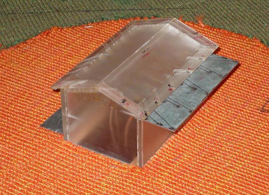
6 height is taken into consideration along with the size (width) of the patio cover. It appears that the study of Jancauskas and Holmes (1985) has been the basis for the development of these provisions in the Australian Standard. Other Studies As previously mentioned, the case of a patio cover has barely been studied in detail; therefore the loads used for wind design are based either on canopy roofs or on open building cases. A very detailed study dealing with wind force coefficients on canopy roofs was carried out by Uematsu et al. (2007, 2008a and 2008b). The wind tunnel experiments were conducted for open terrain exposure and net pressure coefficients were calculated for different canopy roof configurations. Wind Tunnel Study The wind tunnel tests of the present study were conducted in the Building Aerodynamics Laboratory located in the Engineering Complex at Concordia University. A plexi-glass 1:100 building model was used for the experiments. The model has external dimensions of 15 cm by 10 cm (length width) and a total height of 9 cm (ridge height). The gabled roof has a slope of 4:12. The model is equipped with 65 roof pressure taps located both on the top and the bottom of the roof eave. For the current study only specific roof pressure taps were considered and only for verification purposes (comparison to previous studies). In addition to the building model, a metallic patio cover model of the same geometric scale (1:100) was constructed and was mounted on the building model creating the final test model. The patio cover model is 15 cm by 3.65 cm and 0.20 cm thick. In order to consider different 6
7 building configurations, the patio cover was attached on the building model at two different building heights. Three configurations were examined; a two-storey building with the patio cover at the first floor level, a two-storey building with the patio cover at the roof height and a singlestorey building with patio cover at the eave height (see Fig. 1). The patio model was equipped with 30 pressure taps, 15 on the top surface and another 15 on the bottom surface. The building and patio cover model are shown in Fig. 2 and the pressure tap location in Fig. 3. Odd numbers are used for the top surface pressure taps (1.3.5 etc) and even numbers for the bottom surface (2.4.6 etc). The tests were conducted in open terrain simulation characteristics. The value of the power law exponent alpha (α) was 0.14 and the corresponding turbulence intensity at the roof height was approximately 17.5% for the one-storey model and 14% for the two-storey model. These values satisfy the previously addressed importance of proper simulation of turbulence intensity at roof height during wind tunnel testing of low-rise buildings (Tieleman 1998) and also justify the selection of the 1:100 geometric scale. Using the appropriate terrain roughness simulation, the wind velocity was measured at different heights at the centre of the wind tunnel test section without the model in place. The analysis of the measured velocities gave the ratio of the longitudinal wind velocity over the wind velocity at the gradient height ( z/vg), which is also compared with the analytical curve obtained from the power law for α=0.14. This is presented along with the turbulence intensity profile (Vrms/ z) in Fig. 4. The instrumentation used for the wind tunnel tests consisted of a hotwire anemometer (wind velocity and turbulence intensity profiles) and a system of sensitive pressure scanners (Scanivalve DSM3000 and ZOC33/64 Px ). A total number of 28 wind attack angles were 7
8 examined - see Fig. 5. The scanning frequency was 250 Hz and the duration of the record was 36 seconds, values that adequately simulate the dynamic properties of wind-induced pressures to an equivalent full-scale duration of one hour. All acquired data were analyzed and transformed into dimensionless pressure coefficients based on the following equation: c p,mean/peak where: p mean / peak 1 V 2 p 2 h a (1) ρ : the air density (kg/m 3 ) V h : the wind velocity at the mid-roof height (m/s) pa : the ambient atmospheric pressure (Pa) pmean/peak : the actual mean or peak value of the surface pressure (Pa) Results and Discussion Comparison to Previous Experimental Studies The results of the current study are compared with data from previous studies with similar configurations (Stathopoulos and Luchian 1994) to verify the accuracy of the conducted experiments. It should be mentioned that this section refers only to pressure taps located on the roof eaves and not on the patio cover. Moreover, the previously conducted experimental studies were not performed with the patio cover attached to the building model. The geometric details and differences between the test models used are presented in Fig. 6. The comparison between the results of the current study and those of Stathopoulos and Luchian (1994) is presented in Fig. 7. These scatter plots consider all three Configurations (I, II, and III) of the current study and compare the top, bottom and net peak pressure coefficients to the reference study. Despite the 8
9 variations on the geometry (eave height and width) and the presence of the patio cover, the agreement is satisfactory with the overall correlation coefficient exceeding 0.80 and slope deviation smaller than 3 o. Local Pressure Coefficients The wind tunnel patio cover model was equipped with pressure taps both on top and bottom surfaces. This allows the real-time monitoring of wind pressure/suction on each side and most importantly the calculation of the net component. Figs. 8 and 9 demonstrate the total alleviating effect of wind flowing on both sides of the patio cover. The contour plots of the top, bottom and net mean (Fig. 8) and peak (Fig. 9) pressure coefficients are presented for Configuration I and the particular case of 30 o wind direction. Both top and bottom surfaces experience pressures that reach the values of (mean) and (peak) in their dimensionles form (Cp). On the contrary, the net mean pressure coefficient, or in other words the total wind effect on the patio cover, is significantly lower with critical values close to (mean) and (peak). Configurations II and III showed similar relaxing results when considering the simultaneous effect of both upper and lower surface wind flow. The combined effect of top and bottom surface pressure contributions is also demonstrated through correlation analysis of the upper and lower pressure traces. Peak values are not likely to occur simultaneously for both surfaces, therefore the applied net pressure is in some cases significantly lower compared to the difference of the individually observed top and bottom pressures. Two representative azimuths were selected (30 and 135 degrees) and correlation coefficients were evaluated for each pair of top and bottom pressure taps. The results are presented as contour plots for each configuration (I, II and III) and wind direction in Fig. 10. Configurations 9
10 II and III show a similar pattern which is more pronounced for the case of 135 degrees wind direction. As expected, the two pressure traces on top and bottom surfaces are better correlated for Configuration I; indeed the roof irregular geometry does not disturb the flow at lower levels (i.e. patio cover height). Also when the patio is located on the windward side (30 degrees) higher correlations occur for regions closer to the wall the patio is attached to, as opposed to the case of 135 degrees wind direction that results into slightly higher correlations for the opposite corner on the front edge region of the patio. Finally, results indicate in general higher correlation for Configurations I and III which could be related to the fact that patio cover is located at a lower height. In addition to the results for these two wind directions, the variation of the correlation coefficient versus the wind azimuth for three representative sets of top and bottom pressure taps is presented in Fig. 11. The location of these pressure tap pairs is on the corner (pressure taps 1-2), the front edge (pressure taps 13-14) and the patio-to-wall edge (pressure taps 17-18) regions. The results indicate that, in general, Configuration I shows higher correlation values compared to the other two Configurations. Moreover, as indicated previously, lower correlation values occur for the front edge pressure tap sets (1-2 and 13-14) when these are upstream of the actual building. The set of pressure taps located on the patio-to-wall region (17-18) shows the most uniform behaviour and least dependent on wind direction. An important aspect of the wind tunnel experiments, especially for design purposes, was to evaluate the worst pressures/suctions that the patio cover experiences. The critical net pressure coefficients have been calculated through integration of the worst values considering all tested directions (see Fig. 5) this time. The contour plots from this analysis approach are presented in Figs. 12, 13 and 14 for Configuration I, II and III respectively and include the critical positive 10
11 mean pressure coefficients (maximum values of all means, noted as Cp, mean (max)), the critical negative mean pressure coefficients (minimum values of all means, noted as Cp, mean (min)), the critical positive peak pressure coefficients (maximum values of all peaks, noted as Cp, max) and the critical negative peak pressure coefficients (minimum values of all peaks, noted as Cp, min). In agreement to the previous results, the pressure contour patterns show more similarities for Configurations II and III for which the patio is closer to the roof eave. Configuration I experiences the highest positive peak pressure coefficients (+1.40) whereas mean and peak suctions for Configuration II are significantly higher (minimum net pressure coefficient of -2.80) compared to the other two Configurations examined. Some practitioners consider patio covers, when at the eave level, as an extension of the roof. By doing so, the design wind load for the patio becomes identical to that of the overhangs. In order to evaluate the applicability of this assumption, net pressure coefficients measured on the patio were compared with those measured on the roof overhang. The results are grouped in two scatter plots, first for the corner region and then for the edge region and are presented for all three patio cover configurations in Fig. 15. Mean, minimum and maximum net pressure coefficients are compared for each model configuration with the corresponding values required at the overhang section of the roof. The results for these comparisons indicate differences between patio and roof overhang net upward pressure coefficients - the latter are always higher. Differences become more critical for Configuration I, especially on the corner region. The results also indicate a reduction effect on the roof net pressure coefficients when the patio cover is located closer to the roof eave (Configurations II and III). In general, non-critical wind-induced pressures (i.e. positive net pressure effect) on patio covers are of similar magnitude to those on overhangs, whereas the most critical suctions (i.e. negative net pressure effect) are in all cases 11
12 lower on patio covers. The flow characteristics over and below the patio cover are similar to those of a thin plate immersed in a boundary layer flow. Both surfaces experience a suction effect due to flow separation. This is the case when the patio cover is on the windward side of the building. For all other wind angles of attack the building practically shields the patio cover resulting into lower overall wind action mainly due to flow re-attachment phenomena. Comparison with AS/NZS :2002 Of great interest is to compare the findings of this study to those derived by available building codes and standards. The Australian Standard provisions for attached canopies, awnings and carports are based on wind tunnel studies (Jancauskas and Holmes 1985) and consist of net pressure coefficients for two main directions. These experiments were carried out for Category 2 exposure (AS/NZS classification), which corresponds to relatively higher levels of turbulence intensity at the patio cover height compared to the current study. In addition the building model had length to width ratio equal to one (ratio for current study is 1.5), roof slope 15 o (roof slope for current study is 19 o ) and no roof eaves. Finally, almost all of the configurations examined by Jancauskas and Holmes (1985) used a half building-length patio cover (patio cover to building length ratio equal to 0.47). The comparison of wind tunnel values with those from the Australian Standards in terms of net pressure coefficients is presented in Fig. 16 (0/90/270 degrees wind direction). The AS/NZS proposed values refer to 3-sec gust values, therefore appropriate transformation was made to the current study s wind tunnel values (i.e. divided by figure C6-4, ASCE/SEI 7-05). In addition, both the area reduction factor (AS/NZS D1.2) and the local net pressure factor (AS/NZS D1.3) described in section D4.1 of the Australian Standard have not been considered. 12
13 The later may be applicable for areas smaller than 0.25a 2, which for the current study and specific patio cover geometry is equal to 0.13 m 2, located on a corner zone 0.73 by 0.73 m. Even if the intent of the AS/NZS 1170 were to include these factors, their overall effect would be negligible. The agreement between the results of the current study for the specific wind directions mentioned in the Australian standard is in most cases quite good, with some discrepancies observed mainly for Configuration III and wind direction parallel to the attached wall. However, it should be mentioned that for these specific wind directions (90/270 degrees) the AS/NZS considers the patio cover as a free-standing roof. It is also interesting that a net pressure coefficient equal to 0.00 is designated in AS/NZS for some particular cases corresponding to a limited number of azimuths. However, the wisdom of specifying a zero value in a standard is at best questionable given that particular higher values would be dominant in the same areas for, say, quarterly winds. Unfortunately, the lack of sufficient justification on the derivation of the net pressure coefficients provided by the AS/NZS standard does not allow for further comparisons and more detailed discussion. Comparison with ASCE 7-05 ASCE 7-05 provides design pressure coefficients for roof overhangs (Figures 6-11B, C and D). Occasionally attached patio covers at the eave level are considered as roof extensions; therefore, values from Figure 6-11C (Gable/Hip Roofs 7 o < θ 27 o ) of ASCE 7-05 were compared to those obtained from the current study. Using single or multiple sets of pressure taps the variations of the maximum and minimum peak net pressure coefficient were derived with respect to the corresponding effective surface area. The resulting polylines were superimposed as 13
14 shown in Fig. 17. Similarly to AS/NZS standard, the ASCE 7-05 proposed values consist of pressure coefficients based on the 3-sec gust wind velocity pressure, therefore appropriate transformation was made to the wind tunnel pressure coefficient results, as with the comparison with the AS/NZS standard. The results clearly show that such ASCE 7 values overestimate net wind suctions (uplift force) but conform to the net wind pressures. For the negative net pressure coefficients (force upwards) all configurations tested show significantly lower values than those in ASCE 7-05 for eaves. Recommendations Figure 18 shows proposed design net pressure coefficients GCp for patio covers recommended for possible inclusion in ASCE 7. Measured values have been enveloped to reflect the most critical configuration and wind direction by following the same procedure as with the rest of codified pressure coefficients for roof surfaces of low-rise buildings. In addition a summary of all AS/NZS suggested values, presented in Fig. 16, have been included in the same chart. These values have been considered as local pressures (smaller tributary area) and have been grouped into positive and negative sets. The comparison indicates that all of the AS/NZS values are located between the recommended by the current study envelope based design values. The recommended design net pressure coefficients have been deliberately maintained at a higher level to cover for the limited geometries and configurations examined in the wind tunnel study. For simplicity purposes, no edge / corner zones have been determined on the patio cover. Conclusion 14
15 Wind tunnel experimental findings were presented and compared with previous wind tunnel studies and two wind standards for the case of an open patio cover attached to a dwelling unit. Mean and peak local surface wind coefficients were measured for three patio configurations. In addition to the pressure distribution, the correlation between pressures on the top and bottom surfaces of the patio cover was evaluated in order to assess the combined effect of wind-induced forces acting on both sides of such structure. The patio cover local wind pressure coefficients were found to be lower than those measured on the roof eaves. This justifies concerns related to the conservative design approach when patio covers are treated as roof extensions and is also reflected on the overestimated pressure coefficient values derived by the ASCE standard. In addition, local and overall wind pressure coefficients compared to the AS/NZS standards show general similarities but also some differences, as well. The current study indicates the need to update the available wind standards and include sufficient information for the adequate design of patio covers attached to low-rise buildings. Enveloped wind net pressure coefficients for the design of patio covers are proposed for consideration by the ASCE 7 Wind Load Task Committee. References AC340 (2007). Acceptance Criteria for Patio Covers. ICC Evaluation Service, INC, Whittier, CA. ASCE/SEI 7-05 (2005). Minimum Design Loads for Building and Other Structures. American Society of Civil Engineers, Reston, VA. 15
16 AS/NZS (2002). Australian/New Zealand Standards, Structural design actions Part 2, Wind Actions. Standards Australia International Ltd (Sydney) Standards New Zealand (Wellington). BS (1997). Loading for Buildings Part 2: Code of Practice for Wind Loads. British Standard Institute. Cook, N.J. (1985). The Designer s Guide to Wind Loading of Building Structures. Part 2: Static Pressures, Butterworth Scientific, London, U.K. International Building Code (IBC). (2006). International Code Council, Fall Church, VA. International Residential Code (IRC). (2006). International Code Council, Fall Church, VA. Jancauskas, L. and Holmes, J., (1985). Wind Loads on Attached Canopies, Proc. of the National Conference on Wind Engineering, Texas Tech University, Lubbock, TX. National Building Code of Canada (NBCC). (2005). National Research Council of Canada, Ottawa, ON. pren (2004). Eurocode 1: Actions on Structures General Actions Part 1.4: Wind Actions. CEN. Scanivalve Corporation. (2003). DSM Digital service module, instruction and service manual. Scanivalve Corporation. (2003). ZOC 33/64Px - Electronic pressure scanning module, instruction and service manual. Stathopoulos, T. and Luchian, H.D. (1994). "Wind-Induced Forces on Eaves of Low Buildings." J. Wind Eng. Ind. Aerodyn., Vol. 52, pp
17 Tieleman, H. W., Hajj, M.R, and Reinhold, T.A. (1998). Wind tunnel simulation requirements to asses wind loads on low-rise buildings. J. Wind Eng. Ind. Aerodyn., 74-76, pp Uematsu, Y., Iizumi, E. and Stathopoulos, T. (2007). Wind Force Coefficients for Designing Free-standing Canopy Roofs. J. Wind Eng. Ind. Aerodyn., Vol. 95, 9-11, pp Uematsu, Y., Stathopoulos, T. and Iizumi, E. (2008a). Wind Loads on Free-standing Canopy Roofs: Part 1 Local wind pressures. J. Wind Eng. Ind. Aerodyn., Vol. 96, 6-7, pp Uematsu, Y., Stathopoulos, T. and Iizumi, E. (2008b). Wind Loads on Free-standing Canopy Roofs: Part 2 Overall Wind Forces. J. Wind Eng. Ind. Aerodyn., Vol. 96, 6-7, pp
18 Figure Caption List: Fig. 1. Isometric, front and side views of the building models - Configuration I, II and III. Fig. 2. Building and patio cover wind tunnel model (Configuration II is shown). Fig. 3. Pressure tap location and notation on the roof and the patio cover model. Fig. 4. Wind velocity and turbulence intensity profiles. Fig. 5. Wind directions tested in the wind tunnel. Fig. 6. Building model dimension ratios (Current and Stathopoulos and Luchian, 1994). Fig. 7. Comparison of top, bottom and net eave pressure coefficient results with Stathopoulos and Luchian (1994). Fig. 8. Top, bottom and net mean pressure coefficient contour plots for 30 degrees wind direction (Configuration I). Fig. 9. Top, bottom and net peak pressure coefficient contour plots for 30 degrees wind direction (Configuration I). Fig. 10. Correlation coefficient contour plots for top and bottom pressure signals (30 and 135 degrees wind direction). Fig. 11. Correlation coefficient variation with the wind direction (pressure taps 1-2, and 17-18). Fig. 12. Critical mean and peak net pressure coefficients (Configuration I). Fig. 13. Critical mean and peak net pressure coefficients (Configuration II). Fig. 14. Critical mean and peak net pressure coefficients (Configuration III). Fig. 15. Roof and patio cover critical net pressure coefficient comparison. Fig. 16. Comparison of the AS/NZS suggested net pressure coefficients with the wind tunnel results, for 0 and 90/270 degrees wind directions. Fig. 17. Variation of the peak net pressure coefficient with the area Configuration I, II and III. Fig. 18. Proposed net pressure coefficients for design of patio covers. 1
19
20
21
22 Wind Velocity Profile (Wind Tunnel) Wind Velocity Profile (Power Law, a=0.14) Turbulence Intensity 0.60 Z/Zg Vz/Vg (Vrms/Vz)
23
24 Study Configuration L/W E.H./L (E.H. Full-Scale - m) E.W./L (E.W. Full-Scale - m) R.S. Current I (7.00) 0.05 (0.75) 4:12 II (7.00) 0.05 (0.75) 4:12 III (3.50) 0.05 (0.75) 4:12 Stathopoulos (5.00) 0.05 (3.00) 4:12 & Luchian (10.00) 0.05 (3.00) 4:12 * L:Length, W:Width, E.H.:Eave Height, E.W.:Eave Width, R.S.:Roof Slope
25 8.0 C p,bottom 4.0 St. & Luc C p,top St. & Luc C p,net St. & Luc Current Current Current y = 0.90x R² = y = 0.93x R² = y = 0.93x R² =
26
27

28
29 Conf. I Conf. II Conf. III Pressure Taps Conf. I Conf. II Conf. III Pressure Taps Conf. I Conf. II Conf. III Pressure Taps o 1
30
31
32
33 Roof Cp Corner Region Roof Cp Edge Region 0.0 Patio Cp Patio Cp Cp, max Cp,mean Cp,min Cp, max Cp,mean Cp,min Configuration I Configuration II Configuration III 1
34 Wind Direction 0 o 90 o /270 o Configuration I Region - A B C AS/NZS : Current Study Configuration II Region - A B AS/NZS : Current Study Configuration III Region - A B C AS/NZS : Current Study
35 Region 3/2 - Conf. I Region 3/2 - Conf. II Region 3/2 - Conf. III Region 1 - Conf. I Region 1 - Conf. II Region 1 - Conf. III External Pressure Coefficient, GCp (0.1) (0.9) (9.3) (92.9) Effective Wind Area, ft 2 (m 2 ) , 2 & 3 1
36 Net Pressure Coefficient, GCp Maximum (Envelope) Minimum (Envelope) AS/NZS (Positive) AS/NZS (Negative) (0.1) (0.9) (9.3) (92.9) Effective Wind Area, ft 2 (m 2 ) 1
Terrain classification and exposure factor in the 2005 National Building Code of Canada
 Terrain classification and exposure factor in the 25 National Building Code of Canada Ted Stathopoulos a, Ioannis Zisis a, Kai Wang b a Concordia University, 55 St. Catherine W., Montreal, Canada b formerly
WIND LOADS ON BALUSTRADES. Antonios W. Rofail a, Christian Mans a
 WIND LOADS ON BALUSTRADES Antonios W. Rofail a, Christian Mans a a Windtech Consultants, 19 Willis Street, Wolli Creek, NSW, Australia ABSTRACT: This paper examines the wind loading on impermeable balustrade
Local and overall wind pressure and force coefficients for solar panels
 Local and overall wind pressure and force coefficients for solar panels Ted Stathopoulos, Ioannis Zisis 2, Eleni Xypnitou Department of Building, Civil and Environmental Engineering, Concordia University,
Wind Loads on Rooftop Solar Panel Systems: A Contribution to NBCC 2015
 Wind Loads on Rooftop Solar Panel Systems: A Contribution to NBCC 5 Ted Stathopoulos a, Eleni Xypnitou a, Ioannis Zisis b a Department of Building, Civil and Environmental Engineering, Concordia University,
Wind Pressures on Solar Panels Mounted on Residential Homes
 The 22 World Congress on Advances in Civil, Environmental, and Materials Research (ACEM 2) Seoul, Korea, August 26-3, 22 Wind Pressures on Solar Panels Mounted on Residential Homes Aly Mousaad ALY ) and
PROPOSED CHANGE TO THE 2012 BUILDING CODE O. REG. 332/12 AS AMENDED
 Ministry of Municipal Affairs PROPOSED CHANGE TO THE 2012 BUILDING CODE O. REG. 332/12 AS AMENDED CHANGE NUMBER: SOURCE: B-04-01-11 Ontario-NBC CODE REFERENCE: Division B / 4.1.7. DESCRIPTION OF THE PROPOSED
WIND LOADS ON SOLAR PANEL SYSTEMS ATTACHED TO BUILDING ROOFS. Eleni Xypnitou. A Thesis. The Department. Building, Civil and Environmental Engineering
 WIND LOADS ON SOLAR PANEL SYSTEMS ATTACHED TO BUILDING ROOFS Eleni Xypnitou A Thesis In The Department of Building, Civil and Environmental Engineering Presented in Partial Fulfillment of the Requirements
WIND LOADS ON BUILDINGS MWFRS (ENVELOPE PROCEDURE)
") Chapter C28 WIND LOADS ON BUILDINGS MWFRS (ENVELOPE PROCEDURE) The Envelope Procedure is the former low-rise buildings provision in Method 2 of ASCE 7-05 for MWFRS. The simplified method in this chapter
Chapter C28 WIND LOADS ON BUILDINGS MWFRS (ENVELOPE PROCEDURE) The Envelope Procedure is the former low-rise buildings provision in Method 2 of ASCE 7-05 for MWFRS. The simplified method in this chapter
Wind driven flow through building openings
 International Conference Passive and Low Energy Cooling 427 for the Built Environment, May 25, Santorini, Greece Wind driven flow through building openings P. Karava, T. Stathopoulos and A.K. Athienitis
Wind-Induced Torsional Loads on Low- and Medium-Rise Buildings
 Wind-Induced Torsional Loads on Low- and Medium-Rise Buildings Mohamed Ragab Elsharawy A Thesis In the Department of Building, Civil and Environmental Engineering Presented in Partial Fulfillment of the
Analysis of Wind Loads on Buildings and Signs: A Computer Program Based on ASCE 7
 Analysis of Wind Loads on Buildings and Signs: A Computer Program Based on ASCE 7 Dr. H. Estrada* (corresponding author) and Y. Chiu* *Civil Engineering Program Texas A&M University Kingsville MSC 194
Addition. Wind Loads on Rooftop Solar Panels , At a Glance Standard. Wind Loads on Rooftop Solar Panels
 Wind Loads on Rooftop Solar Panels 29.4.3, 29.4.4 At a Glance New provisions for determining wind loads on solar panels on buildings have been added to ASCE 7-16. One method applies specifically to low-sloped
International Journal of Advanced Engineering Technology E-ISSN
 International Journal of Advanced Engineering Technology E-ISSN 0976-3945 Research Article WIND INTERFERENCE ON SINGLE SIMILAR GABLE ROOF BUILDING WITH OVERHANGS Narayan K a *, Gairola A b Address for
Impact of C&C loads due to ASCE/SEI Overview Revised 3/23/2017
 Impact of C&C loads due to ASCE/SEI 7-16 Overview Revised 3/23/2017 SBCA has been the voice of the structural building components industry since 1983, providing educational programs and technical information,
Wind loads at solar and photovoltaic modules for large plants
 Ruscheweyh Consult GmbH Aachen Veröffentlichung Wind loads at solar and photovoltaic modules for large plants Hans Ruscheweyh, Reiner Windhövel Ruscheweyh Consult GmbH, Teichstr. 8, Aachen, Germany, info@ruscheweyh.de
THE PREDICTION OF WIND LOADS ON BUILDING ATTACHMENTS
 THE PREDICTION OF WIND LOADS ON BUILDING ATTACHMENTS C. Mans 1, G. A. Kopp, D. Surry Boundary Layer Wind Tunnel Laboratory The University of Western Ontario, London, Ontario, Canada, N6A 5B9 1 Corresponding
ROOF FRAMING ANCHORAGE FORCES: MWFRS
 TECHNICAL NOTE On Cold-Formed Steel Construction 1201 15th Street, NW, Suite 320 W ashington, DC 20005 (202) 785-2022 $5.00 ROOF FRAMING ANCHORAGE FORCES: MWFRS or C&C Summary: This Technical Note defines
Vulnerability modelling of metal-clad industrial buildings to extreme wind loading
 Vulnerability modelling of metal-clad industrial buildings to extreme wind loading *K.M. Chaminda Konthesingha 1),Mark G. Stewart 2), John Ginger 3), David Henderson 4) 1), 2) Centre for Infrastructure
Response of Metal Roofs to Uniform Static and True Hurricane Wind Loads
 Missouri University of Science and Technology Scholars' Mine International Specialty Conference on Cold- Formed Steel Structures (2008) - 19th International Specialty Conference on Cold-Formed Steel Structures
Torsional and Shear Wind Loads on Flat-Roofed Buildings
 Torsional and Shear Wind Loads on Flat-Roofed Buildings Mohamed Elsharawy, Khaled Galal, Ted Stathopoulos Faculty of Engineering and Computer Science, Concordia University, Montréal, Québec, Canada ABSTRACT:
PERFORMANCE OF AN AUXILIARY NATURAL VENTILATION SYSTEM
 PERFORMANCE OF AN AUXILIARY NATURAL VENTILATION SYSTEM A.W. Rofail and L.J.Aurelius 1.0 INTRODUCTION A comprehensive wind tunnel study has been carried out by Windtech Consultants Pty Ltd to establish
2012 Wood Frame Construction Manual: Wind Speed and Design Pressure Determination According to ASCE 7 10
 2012 Wood Frame Construction Manual: Wind Speed and Design Pressure Determination According to ASCE 7 10 Presented by: William L. Coulbourne, PE Copyright Materials This presentation is protected by US
In te current study, wind-induced torsional loads on low and medium eigt buildings were examined in te boundary layer wind tunnel. uilding model (scal
 Te Sevent International Colloquium on luff ody Aerodynamics and Applications (AA7) Sangai, Cina; September 2-6, 2012 Wind-induced torsional aerodynamic loads on low and medium eigt buildings M. Elsarawy,
RESILIENT INFRASTRUCTURE June 1 4, 2016
 RESILIENT INFRASTRUCTURE June 1 4, 2016 RISK ANALYSIS OF WIND LOADING INCLUDING FUTURE CHANGES IN SURROUNDING BUILDINGS Peter A. Irwin RWDI, Guelph, ON, Canada Jeff Stanton RWDI, Guelph, ON, Canada ABSTRACT
boundary layer wind flow. Measured wind pressures were expanded from limited measurement points to all the structural nodes using the orthonormal coor
 Internal stresses in cladding support members of long-span arched roof under wind load hibin Ding a, Yukio Tamura a, Akihito Yoshida a a Tokyo Polytechnic University, Iiyama 1583, Atsugi, Kanagawa, Japan
Wind Load Report - Naples Residence
 Wind Load Report - Naples Residence 1. Site & Building Data Roof Type: Gable Wind Speed (ult): 115 mph Exposure Category: C Enclosure Class: Enclosed Building Width (W): 20 ft. Building Length (L): 23
ASCE 7-16: Changes to Wind Calculations for Rooftop Solar
 ASCE 7-16: Changes to Wind Calculations for Rooftop Solar Joe Cain, P.E. Chair, SEIA Codes & Standards Working Group David Banks, PhD, P.Eng Principal Cermak Peterka Petersen (CPP) ASCE 7-16: Changes to
DYNAMIC WIND LOADING OF H-SHAPED TALL BUILDINGS
 The Seventh Asia-Pacific Conference on Wind Engineering, November 8-12, 2009, Taipei, Taiwan DYNAMIC WIND LOADING OF H-SHAPED TALL BUILDINGS K. M. Lam 1, S. Y. Wong 1 and A. P. To 2 1 Department of Civil
Patio Cover Manufacturers and other Interested Parties
 To: From: Patio Cover Manufacturers and other Interested Parties ICC-ES Date: February 6, 2009 Subject: Technical Review of Patio Cover Engineering Analysis in Accordance for Patio Covers (AC340) MEMO
Wind Load Report - Check for uplift
 Wind Load Report - Check for uplift 1. Site & Building Data Roof Type: Gable Wind Speed (ult): 115 mph Exposure Category: C Enclosure Class: Enclosed Building Width (W): 43 ft. Building Length (L): 60
Performance of the Acrylife Roof Vent
 Performance of the Acrylife Roof Vent Murray J. Morrison, PhD, Anne D. Cope, PhD, P.E., Timothy A. Reinhold, PhD, P.E. Report: IBHS-12XX01 August 31, 2012 Prepared for: Acrylife 1165 Stafford Umberger
WIND-DRIVEN RAIN ON THE WALLS OF BUILDINGS IN METRO VANCOUVER: PARAMETERS FOR RAIN PENETRATION TESTING
 WIND-DRIVEN RAIN ON THE WALLS OF BUILDINGS IN METRO VANCOUVER: PARAMETERS FOR RAIN PENETRATION TESTING ABSTRACT K. Ronald and H. Ge Laboratory tests conducted on building assemblies to assess their resistance
Dynamic Time-history Analysis on Wind-induced Response of Light-weight Roof System
 Missouri University of Science and Technology Scholars' Mine International Specialty Conference on Cold- Formed Steel Structures (2012) - 21st International Specialty Conference on Cold-Formed Steel Structures
Wall Pressure Coefficients for Low- to High-Rise Buildings
 Western University Scholarship@Western Electronic Thesis and Dissertation Repository May 2017 Wall Pressure Coefficients for Low- to High-Rise Buildings Emilio S. Hong The University of Western Ontario
Comparative study of wind tunnel test results to international and Egyptian design codes
 Comparative study of wind tunnel test results to international and Egyptian design codes *Chang- Abdulmonem A. Badri 1), *Manar M. Hussein 2) and Walid A. Attia 3) 1), 2), 3) 1 Department of Structural
LATERAL LOADS ON BRICK VENEER RESIDENTIAL STRUCTURES
 LATERAL LOADS ON BRICK VENEER RESIDENTIAL STRUCTURES W. Mark McGinley 1, PhD, PE and Eric N. Johnson 2, PE ABSTRACT In North American residential construction, brick veneer is typically used as a cladding
Benchmark Buildings for an International HFBB Comparison
 Benchmark Buildings for an International HFBB Comparison Introduction The High Frequency Base Balance (HFBB) (also known as the High-Frequency Force Balance (HFFB)), has been widely used as a wind-tunnel
16.4 FLORIDA BUILDING CODE BUILDING
 1604.8-1606.1.2 5. Designs using NAAMM FP-1001 Specification for Design Loads of Metal Flagpoles. 6. Subject to the limitations of 1606.1.1.1, 1606.1.4, and 1606.1.6, the provisions of the FC&PA Guide
ANSI/SPRI Wind Design Standard Practice for Roofing Assemblies
 Approved September 3, 2008 ANSI/SPRI WD-1 ANSI/SPRI Wind Design Standard Practice for Roofing Assemblies TABLE OF CONTENTS Section Page 1.0 INTRODUCTION...........................................................
Wind loads on solar energy roofs
 Wind loads on solar energy roofs Chris P.W. Geurts, Carine A. van Bentum TNO Built Environment and Geosciences, Delft, the Netherlands This paper presents an overview of the wind loads on roofs, equipped
G.Muttrah Commercial & Residential Complex Muscat, Sultanate of Oman
 G.Muttrah Commercial & Residential Complex Muscat, Sultanate of Oman Technical Report III Samir Al-Azri Structural Option Consultant: December 1 st, 2009 Page 1 Table of Contents I. Executive summary.
DIVISION: THERMAL AND MOISTURE PROTECTION SECTION: METAL ROOF PANELS SECTION: METAL WALL PANELS REPORT HOLDER:
 0 Most Widely Accepted and Trusted ICC ES Evaluation Report ICC ES 000 (800) 4 6587 (562) 699 0543 www.icc es.org ESR 3152 Reissued 08/2017 This report is subject to renewal 08/2018. DIVISION: 07 00 00
ABSTRACT. Assistant Professor, Brian M. Phillips (Chair) Professor, Bilal M. Ayyub, P.E. (Co-Chair) Dept. of Civil and Environmental Engineering
 Professor, Bilal M. Ayyub, P.E. (Co-Chair) Dept. of Civil and Environmental Engineering") ABSTRACT Title of Document: REEVALUATION OF ASCE 7-10 EXTERNAL PRESSURE COEFFICIENTS ON THE COMPONENTS AND CLADDING OF LOW-RISE BUILDINGS USING MODERN WIND TUNNEL TESTING DATA Matthew Lloyd Gierson, M.S.,
ABSTRACT Title of Document: REEVALUATION OF ASCE 7-10 EXTERNAL PRESSURE COEFFICIENTS ON THE COMPONENTS AND CLADDING OF LOW-RISE BUILDINGS USING MODERN WIND TUNNEL TESTING DATA Matthew Lloyd Gierson, M.S.,
Residential Patio Cover Specifications
 Residential Patio Cover Specifications This information bulletin describes the minimum requirements for obtaining patio cover permits for residential buildings using the City of Vista standard plan or
Design Example 1 Enclosure Classification
 Design Example 1 Enclosure Classification OVERVIEW An enclosure classification is a way of assigning a classification to a building to determine the appropriate amount of internal pressure generated. Internal
Effect of Wind and Structural Parameters on Wind-Induced Acceleration of RC Building
 ISBN 978-93-84468-11-8 Proceedings of International Conference on Architecture And Civil Engineering (ICAACE'14) Dubai, December 5-6, 14, pp. 135-149 Effect of Wind and Structural Parameters on Wind-Induced
Multi-scale methodology to assess wind loads on building louvers
 8 th International Colloquium on Bluff Body Aerodynamics and Applications Northeastern University, Boston, Massachusetts, USA June 7-11, 2016 BBAA VIII Multi-scale methodology to assess wind loads on building
Pull-Through Failure Tests of Thin Steel Roof Battens under Wind Uplift Loads
 Missouri University of Science and Technology Scholars' Mine International Specialty Conference on Cold- Formed Steel Structures (2014) - 22nd International Specialty Conference on Cold-Formed Steel Structures
Calculation of Wind Loads on Structures according to ASCE 7-10
 Calculation of Wind Loads on Structures according to ASCE 7-10 Permitted Procedures The design wind loads for buildings and other structures, including the Main Wind-Force Resisting System (MWFRS) and
WIND TUNNEL STUDIES AND THEIR VALIDATIONS WITH FIELD MEASUREMENTS FOR A SUPER-TALL BUILDING
 The Seventh Asia-Pacific Conference on Wind Engineering, November 8-12, 2009, Taipei, Taiwan WIND TUNNEL STUDIES AND THEIR VALIDATIONS WITH FIELD MEASUREMENTS FOR A SUPER-TALL BUILDING Q.S. Li 1, Jiming
ACCURATE LINEAR AND NONLINEAR SEISMIC SSI ANALYSIS BASED ON ANSYS FE MODELING USING EXTENDED SASSI METHODOLOGY
 Transactions, SMiRT-24 II, Paper 468 ACCURATE LINEAR AND NONLINEAR SEISMIC SSI ANALYSIS BASED ON ANSYS FE MODELING USING EXTENDED SASSI METHODOLOGY Dan M. Ghiocel 1, Mike Saremi 2 1 Chief of Engineering
Experimental Investigation of Twisted Bladed Savonius Wind Turbine Rotor
 International Energy Journal: Vol. 5, No. 1, June 2004 1 Experimental Investigation of Twisted Bladed Savonius Wind Turbine Rotor A. S. Grinspan, U. K. Saha and P. Mahanta Department of Mechanical Engineering
ESR-2015P* Reissued April 2014 This report is subject to renewal April 1, 2015.
 ICC-ES Evaluation Report ESR-2015P* Reissued April 2014 This report is subject to renewal April 1, 2015. www.icc-es.org (800) 423-6587 (562) 699-0543 A Subsidiary of the International Code Council DIVISION:
Page 1 of 21
 www.garyklinka.com Page 1 of 21 UDC Wall Bracing Provisions quiz Instructions 1. Print these pages. Fee $30 2. Answer the Simple questions that follow mini sections of the code language. 3. Circle the
Dr. J. Wolters. FZJ-ZAT-379 January Forschungszentrum Jülich GmbH, FZJ
 Forschungszentrum Jülich GmbH, FZJ ZAT-Report FZJ-ZAT-379 January 2003 Benchmark Activity on Natural Convection Heat Transfer Enhancement in Mercury with Gas Injection authors Dr. J. Wolters abstract A
PARAMETRIC CFD WIND FORCE ANALYSIS ON A RESIDENTIAL ROOF MOUNTED PHOTOVOLTAIC PANEL
 PARAMETRIC CFD WIND FORCE ANALYSIS ON A RESIDENTIAL ROOF MOUNTED PHOTOVOLTAIC PANEL Caption: CFD simulation of wind force on photovoltaic roof mounted panel OBJECTIVE Our client was in the process of installing
CALCULATING WIND LOADS ON LOW-RISE STRUCTURES PER 2015 WFCM ENGINEERING PROVISIONS (STD342-1)
") CALCULATING WIND LOADS ON LOW-RISE STRUCTURES PER 015 WFCM ENGINEERING PROVISIONS (STD34-1) John Buddy Showalter, P.E. Vice President, Technology Transfer American Wood Council Description The Wood Frame
CALCULATING WIND LOADS ON LOW-RISE STRUCTURES PER 015 WFCM ENGINEERING PROVISIONS (STD34-1) John Buddy Showalter, P.E. Vice President, Technology Transfer American Wood Council Description The Wood Frame
WIND FLOW IN THE RECESSED CAVITIES OF A TALL
 The Seventh Asia-Pacific Conference on Wind Engineering, November 8-12, 2009, Taipei, Taiwan WIND FLOW IN THE RECESSED CAVITIES OF A TALL BUILDING Charles C.K. Cheng 1, K.M. Lam 2 and Andrew Y.T. Leung
Post Windstorm Evaluation of Critical Aspects Causing Damage to Rural Houses in the Northern Region of Peninsular Malaysia
 Post Windstorm Evaluation of Critical Aspects Causing Damage to Rural Houses in the Northern Region of Peninsular Malaysia Shaharudin Shah Zaini 1,*, Taksiah A. Majid 1, Siti Noratikah Che Deraman 1, Farah
INTERNATIONAL JOURNAL OF CIVIL AND STRUCTURAL ENGINEERING Volume 4, No 3, 2014
 INTERNATIONAL JOURNAL OF CIVIL AND STRUCTURAL ENGINEERING Volume 4, No 3, 2014 Copyright by the authors - Licensee IPA- Under Creative Commons license 3.0 Research article ISSN 0976 4399 Wind loads on
Guide to the Use of the Wind Load Provisions
 Guide to the Use of the Wind Load Provisions About the Authors Kishor C. Mehta, P.E., Honorary Member of ASCE, Horn Professor of Civil Engineering, is the former Director of the Wind Science and Engineering
The Dutch Wind Tunnel Guideline for Wind Loads
 The Dutch Wind Tunnel Guideline for Wind Loads Chris Geurts 1,2, Carine van Bentum 1 and Eddy Willemsen 3 1 TNO, Delft, the Netherlands. chris.geurts@tno.nl 2 Dept of the Built Environment, Eindhoven University
Expert statement on the wind loads impacting solar modules with different inclinations from below
 Dr. Zapfe GmbH Engineering office for constructive engineering and solar planning Dr.-Ing. Cedrik Zapfe Mobile: 0176 19191280 E-Mail: cedrik.zapfe@ing-zapfe.de Alustraße 1 83527 Kirchdorf/Haag i.ob, GERMANY
Towards a reliable design of facade and roof elements against wind loading
 Towards a reliable design of facade and roof elements against wind loading C.P.W. Geurts, P.C. van Staalduinen and M.S. de Wit TNO Building and Construction Research, Delft, The Netherlands The most vulnerable
Snow load design using the 2003 International Building Code
 Snow load design using the 2003 International Building Code By John R. Henry, P.E. Early model building codes transcribed design provisions from various sources and standards. More recent editions of the
Residential Zoning Rules
 Residential Zoning Rules Applications for building permits must contain plans and information that show that the proposal meets the requirements of the International and Washington State building codes,
SEISMIC DESIGN AND RESPONSE OF HEAVY INDUSTRIAL STEEL BUILDINGS
 COMPDYN 211 3 rd ECCOMAS Thematic Conference on Computational Methods in Structural Dynamics and Earthquake Engineering M. Papadrakakis, M. Fragiadakis, V. Plevris (eds.) Corfu, Greece, 25 28 May 211 SEISMIC
Details for Exterior Brick Masonry Veneer Supported by Metal Plate Connected Wood Trusses
 Details for Exterior Brick Masonry Veneer Supported by Metal Plate Connected Wood Trusses Released May 20, 2009 Updated March 9, 2011 Introduction: Wood frame structures with attached brick masonry veneer
7. Seismic Design. 1) Read.
 Read.") 7. Seismic Design Lesson Objectives: 1) Describe code based seismic design in accordance with ASCE 7-16 and IBC 2012. 2) Compute mapped and design spectral accelerations. 3) Categorize and identify the
7. Seismic Design Lesson Objectives: 1) Describe code based seismic design in accordance with ASCE 7-16 and IBC 2012. 2) Compute mapped and design spectral accelerations. 3) Categorize and identify the
American Residential Deck Railing Design Guide
 American Residential Deck Railing Design Guide Intended for use by Designers & Architects Engineers & Professional Installers 8 th Edition Updated Nov. 2017 ProbuiltRailings.com ` LIST OF FIGURES ProBuilt
Florida Structural Engineers
 Florida Structural Engineers South Florida Chapter January 8, 2008 Miami Lakes, Florida Aluminum Association of Florida, Inc. Joe Belcher ~ David Miller AAF Code Involvement: Historical Perspective 1998:
Structural provisions and loading. with an appropriate paint system, for example specified with a Duragal finish or alternatively galvanized.
 Structural provisions and loading Overview Wind loads can prove particularly challenging for greenhouses in Australian conditions. It s important to note what the following terms mean: Windward is toward
INTERNATIONAL ASSOCIATION OF PLUMBING AND MECHANICAL OFFICIALS UNIFORM EVALUATION SERVICES EVALUATION CRITERIA FOR
 INTERNATIONAL ASSOCIATION OF PLUMBING AND MECHANICAL OFFICIALS UNIFORM EVALUATION SERVICES EVALUATION CRITERIA FOR THE TESTING AND ANALYSIS OF STEEL SHEET SHEATHING FOR WOOD AND COLD FORMED STEEL LIGHT
Structural Criteria for Residential Rooftop Solar Energy Installations
 TOOLKIT DOCUMENT #5 Structural Criteria for Residential Rooftop Solar Energy Installations Use of this document This toolkit document includes a one-page list of structural criteria for espedited approval,
DynoRaxx EVOLUTION PR Guide to Code Compliant Installation
 DynoRaxx EVOLUTION PR Guide to Code Compliant Installation Publication Number 100611 866.620.2410 dynoraxx.com Table of Contents I. Installer Responsibilities... 3 II. Simplified Procedure for Calculating
There have been many instances of aircraft hangars roof systems
 Photo 1: A substantial amount of roof deck material blew off these hangars. At one hangar, many trusses also were blown away. Two nearby fighter aircraft appeared to be damaged, as well. There have been
Can we build disaster resilient communties? A new look at wind effects on houses
 Can we build disaster resilient communties? A new look at wind effects on houses Can we build disaster resilient communties? A new look at wind effects on houses Gregory A. Kopp Boundary Layer Wind Tunnel
Load Design Charts. R-CONTROL SIPs STRUCTURAL INSULATED PANELS. CONTROL, NOT COMPROMISE.
 R-CONTROL s STRUCTURAL INSULATED PANELS Note: Information deemed reliable at time of printing. Please visit www.r-control.com for latest information. June 2012 CONTROL, NOT COMPROMISE. www.r-control.com
Analysis of Shear Wall Transfer Beam Structure LEI KA HOU
 Analysis of Shear Wall Transfer Beam Structure by LEI KA HOU Final Year Project report submitted in partial fulfillment of the requirement of the Degree of Bachelor of Science in Civil Engineering 2013-2014
DIVISION: THERMAL AND MOISTURE PROTECTION SECTION: ROOFING AND SIDING PANELS REPORT HOLDER: FOUR SEASONS BUILDING PRODUCTS, LLC
 0 Most Widely Accepted and Trusted ICC ES Evaluation Report ICC ES 000 (800) 423 6587 (562) 699 0543 www.icc es.org ESR 2229 Reissued 05/2018 This report is subject to renewal 05/2019. DIVISION: 07 00
Structural Criteria for Residential Rooftop Solar Energy Installations
 PV TOOLKIT DOCUMENT #5 Structural Criteria for Residential Rooftop Solar Energy Installations Use of this document This toolkit document includes a one-page list of structural criteria for over-the-counter
SHAKE-TABLE TESTING OF A 3-STORY, FULL-SCALE, REINFORCED MASONRY WALL SYSTEM
 15 th International Brick and Block Masonry Conference Florianópolis Brazil 2012 SHAKE-TABLE TESTING OF A 3-STORY, FULL-SCALE, REINFORCED MASONRY WALL SYSTEM Stavridis, Andreas 1 ; Mavridis, Marios 2 ;
Streamline Solar Photovoltaic Structural Criteria for Residential Rooftop Solar Energy Installations (Streamline Solar Form 5)
") TOOKIT DOCUMENT #5 Streamline Solar Photovoltaic Structural Criteria for Residential Rooftop Solar Energy Installations (Streamline Solar Form 5) Use of this document This toolkit document includes a one
TOOKIT DOCUMENT #5 Streamline Solar Photovoltaic Structural Criteria for Residential Rooftop Solar Energy Installations (Streamline Solar Form 5) Use of this document This toolkit document includes a one
AREA-AVERAGED CHARACTERISTICS OF WIND LOADS ON ROOF-MOUNTED SOLAR ARRAYS
 The Eighth Asia-Pacific Conference on Wind Engineering, December 4, 3, Chennai, India AREA-AVERAGED CHARACTERISTICS OF WIND LOADS ON ROOF-MOUNTED SOLAR ARRAYS Jinxin Cao, Yukio Tamura, Akihito Yoshida
Wind loads on solar panels mounted on flat rooftops: Progress and limitations
 Wind loads on solar panels mounted on flat rooftops: Progress and limitations Zhitian Zhang 1)* and *Ted Stathopoulos 2) 1) Wind Engineering Research Center, Hunan University, Changsha, China 2) Department
Be sure to read and completely understand these guidelines before attempting to install this Power-Fab product.
 PRECAUTIONS PRECAUTIONS Be sure to read and completely understand these guidelines before attempting to install this Power-Fab product. These design guidelines are not intended to supersede any company,
FEM ANALYSIS OF TILE ROOFS UNDER SIMULATED TYPHOON IMPACT
 The Seventh Asia-Pacific Conference on Wind Engineering, November 8-12, 29, Taipei, Taiwan FEM ANALYSIS OF TILE ROOFS UNDER SIMULATED TYPHOON IMPACT Peng Huang 1, Ming Gu 2, Amir Mirmiran 3, Arindam Gan
PROPOSED CHANGE TO THE 2012 BUILDING CODE O. REG. 332/12 AS AMENDED
 Ministry of Municipal Affairs PROPOSED CHANGE TO THE 2012 BUILDING CODE O. REG. 332/12 AS AMENDED CHANGE NUMBER: SOURCE: B-04-01-09 Ontario-NBC CODE REFERENCE: Division B / 4.1.6. DESCRIPTION OF THE PROPOSED
SIMPLIFIED ESTIMATION OF CRITICAL TEMPERATURES OF PORTAL FRAMES IN FIRE
 SIMPLIFIED ESTIMATION OF CRITICAL TEMPERATURES OF PORTAL FRAMES IN FIRE by S.Y. Wong 1, I.W. Burgess 1 and R.J. Plank 2 1 Department of Civil & Structural Engineering, University of Sheffield, UK. 2 School
Applying IBC 2000 wind and snow loads to post-frame building posts
 Applying IBC 2000 wind and snow loads to postframe building posts By Patrick M. McGuire, P.E., and Brent Leatherman, P.E. Introduction The International Building Code 2000 edition (IBC, 2000) is a compilation
Association of Caribbean States 2003
 MODEL BUILDING CODE FOR WIND LOADS Final Version, May 2003 Association of Caribbean States 2003 5-7 Sweet Briar Road, St. Clair, P.O. Box 660 Port of Spain, Trinidad and Tobago, West Indies Tel: (868)
Modelling the seismic response of light-timber-framed buildings
 Modelling the seismic response of light-timber-framed buildings B.L. Deam & P.J. Moss Wood Technology Research Centre and Department of Civil Engineering, University of Canterbury, Christchurch NZSEE 2001
VERTICAL AND HORIZONTAL LATERAL LOAD SYSTEMS
 TECHNICAL NOTE On Cold-Formed Steel Construction $5.00 Light Gauge Steel Engineers Association Washington, D.C. Toll-Free: 1 (866) 465-4732 www.lgsea.com DESIGN VALUES FOR VERTICAL AND HORIZONTAL LATERAL
Structural Criteria for Residential Rooftop Solar Energy Installations
 SWH TOOLKIT DOCUMENT #4 Structural Criteria for Residential Rooftop Solar Energy Installations Use of this document This toolkit document includes a one-page list of structural criteria for over-the-counter
Full Paper Proc. of Int. Conf. on Advances in Civil Engineering 2012
 Behaviour of R.C.C. Tall Buildings Having Different Shapes Subjected to Wind Load Prof. Sarita Singla 1, Taranjeet Kaur 2, Megha Kalra 3 and Sanket Sharma 4 1 Email:ssaritasingla@yahoo.com 2 Baddi University/Civil
Understanding IBC Wind Load Requirements for Generating Systems
 Understanding IBC Wind Load Requirements for Generating Systems By: Allan Bliemeister Senior Staff Engineer Kohler Power Systems It is important for standby power system enclosures to withstand loads produced
Scope. resistance expressed as a moment
 ROOFING APPLICATION STANDARD (TAS) No. 102-95 TEST PROCEDURE FOR STATIC UPLIFT RESISTANCE OF MECHANICALLY ATTACHED, RIGID ROOF SYSTEMS [For Mechanically Attached, Rigid Roof Systems Accompanied by a Clip,
DIVISION: SPECIALTIES SECTION: PROTECTIVE COVERS REPORT HOLDER: FOUR SEASONS BUILDING PRODUCTS, LLC EVALUATION SUBJECT:
 0 Most Widely Accepted and Trusted ICC ES Evaluation Report ICC ES 000 (800) 423 6587 (562) 699 0543 www.icc es.org ESR 1953P Reissued 06/2018 This report is subject to renewal 06/2019. DIVISION: 10 00