Oregon Department of Forestry
|
|
|
- Austen Harmon
- 5 years ago
- Views:
Transcription
1 Oregon Department of Forestry State Forests Program Forest Roads Manual Roads Manual i July 2000
2 Acknowledgments The Oregon Department of Forestry, State Forests Program has developed this manual. Development has been through a team effort of the following people, all Oregon Department of Forestry employees: Scott Wilbrecht, project leader; Tony Klosterman, Bill Metcalf, Dave Michael, Greg Miller, and Darrel Spiesschaert, final editing. Without their valuable participation, this project would not have been possible. I extend my gratitude for their help and understanding on this undertaking that became more work than any of us envisioned. Other Resource Specialist providing input and draft review: Keith Mills, Forest Practices Geotechnical Specialist, Oregon Department of Forestry Ross Holloway, Policy and Planning Manager, Oregon Department of Forestry Rosemary Mannix, Technical Services Manager, Oregon Department of Forestry Many Oregon Department of Forestry Engineers, Road Specialists and Foresters from around the state. Special thanks to Oregon State University's Forest Engineering Department for draft review by Brian W. Kramer, P.E. Special thanks for many of the graphic illustrations provided from the Forest Practices Program's " Forest Road Management Guidebook". Cover Design: Laura Lynn, Oregon Department of Forestry, Graphics Department Contact for information: Scott Wilbrecht Oregon Dept. of Forestry Forest Engineering Coordinator 2600 State Street Salem, OR swilbrecht@odf.state.or.us Roads Manual ii July 2000
3 Forest Engineering Roads Manual June 2000 Table of Contents Section 1. Introduction Road Management Policy 1-1 Purpose of the Manual 1-2 The Vision for Forest Roads on State-owned Forest Lands 1-2 Guiding Principles for Road Management 1-2 Road Density 1-2 Road Location 1-3 High-risk Sites 1-3 Economic, Efficient and Effective 1-3 Road Design 1-3 Temporary Roads 1-4 Drainage of Surface Water 1-4 Fish Passage 1-4 Waste Areas 1-5 Rock Pits and Quarries 1-5 Road Maintenance 1-5 Vacating Road 1-6 Section 2. Transportation Planning Introduction 2-1 Goals of Transportation Planning 2-1 Objectives of Transportation Planning 2-1 Levels of Planning 2-1 Transportation Planning Strategies 2-3 Develop a Vision of the Transportation System 2-3 Inventory and Describe the Current Conditions 2-3 Develop Transportation Plans Consistent With the Planning Level 2-4 Section 3. Forest Road Design Introduction 3-2 Roads Manual iii July 2000
4 Goals of Road Design 3-2 Objectives of Road Design 3-2 Road Design Strategies 3-3 Engineering Procedures 3-3 Base Level Engineering Procedures 3-4 Mid-Level Engineering Procedures 3-4 Upper Level Engineering Procedures 3-5 Road Design Standards 3-6 Design Standards for Low Use Roads 3-6 Design Standards for Medium Use Roads 3-7 Design Standards for High Use Roads 3-7 Road Design Criteria 3-8 Coordinated Planning and Location of Roads 3-8 Reconnaissance 3-8 Road Location 3-8 Road Prism Design 3-9 Road Drainage 3-9 Surface Drainage 3-9 Subgrade Shapes 3-9 Road Grades 3-10 Drainage Structures 3-12 Running Surface 3-14 Special Drainage 3-15 Design of Stream Crossing Structures 3-16 Temporary Road Design by Purchasers of Timber Sale Contracts 3-17 Road Design by Easement Holders 3-17 Road Construction 3-17 Referencing Centerline 3-18 Culvert Referencing 3-19 Cut and Fill Slopes 3-20 Landings And Turnouts 3-21 Curve Widening 3-25 Log Trucks and Yarders 3-25 Lowboy Truck and Trailer 3-25 Curve Widening Diagram 3-26 Maximum Vehicle Off-tracking 3-27 Section 4. Forest Road Construction Introduction 4-1 Goals of Road Construction 4-2 Objectives of Road Construction 4-2 Road Construction Strategies 4-2 Timing 4-2 Clearing and Grubbing 4-3 Options for Disposal of Clearing and Grubbing Debris 4-4 Sidecast 4-4 Roads Manual iv July 2000
5 Scattering 4-4 Pile and Burn 4-5 End-Haul 4-5 Chipping and Scattering 4-5 Balanced Cut and Fill (BCF) Construction 4-6 Full Bench Construction 4-7 Construction on Marginally Stable Slopes 4-8 Grading and Compaction 4-9 Subgrade and Surfacing 4-10 Erosion Control 4-10 Section 5. Forest Road Improvement Introduction 5-1 Goals of Road Improvement 5-2 Objectives of Road Improvement 5-2 Road Improvement Strategies 5-2 Road Improvement Planning 5-3 Road Improvement Design 5-4 Construction of Road Improvement Projects 5-7 Section 6. Project Administration for Road Projects Introduction 6-1 Goals of Project Administration 6-1 Objectives of Project Administration 6-1 Project Administration Strategies 6-2 KSA s for Project Administrators 6-2 Before Construction Begins 6-2 Responsibilities of Contract Administrators During Construction 6-3 Final Inspection and Approval 6-4 Section 7. Forest Road Maintenance Introduction 7-1 Goals of Forest Road Maintenance 7-2 Objectives of Forest Road Maintenance 7-2 Road Maintenance Strategies 7-2 Inventory 7-2 Inspection 7-3 Planning 7-5 Design Standards 7-5 Frequency of Maintenance 7-6 Timing 7-6 Coordination 7-7 Implementation Options 7-7 Department of Forestry and Equipment 7-7 Timber Sale Purchasers 7-7 Roads Manual v July 2000
6 Service Contracts 7-8 KSA s for Maintenance Personnel 7-8 ODF Maintenance Supervisors and Maintenance Personnel 7-8 Contract Administrators (Timber Sale Contracts and Service Contracts) 7-8 Documentation 7-9 Monitoring 7-9 Priority Maintenance 7-9 Road Closure Or Vacation 7-10 Maintenance Functions 7-10 Drainage Maintenance 7-10 Road Surface 7-11 Cut And Fill Slopes 7-11 Erosion Control 7-12 Vegetation Control 7-12 Section 8. Forest Road Vacating Introduction 8-1 Goals of Forest Road Vacating 8-2 Objectives of Forest Road Vacating 8-2 Road Vacating Strategies 8-5 Road Vacating Assessment 8-5 Stream Crossing Excavations 8-6 Road Surface Runoff and Other Drainage Structures 8-6 Treatment of Unstable Areas 8-6 Erosion and Sediment Control 8-7 Blocking the Road 8-7 Timing 8-7 Guidelines for Areas of Special Concern 8-7 Road Proposed for Vacating (form) 8-9 Section 9. Information Management Section 10. Responsibilities State Forests Program Director State Forests Program Staff Engineer Area Director Assistant District Forester/Unit Forester Timber Sale Layout Personnel District Engineer Project Administrator Geotechnical Specialist Roads Manual vi July 2000
7 Section 11. Appendixes Appendix 1. Protocol for Road Hazard Inventories Appendix 2. Exhibits for Timber Sale Contracts/Service Contracts Appendix 3. Costs Related to Road Construction/Improvement Appendix 4. Work Forms Appendix 5. List of Useful References Roads Manual vii July 2000
8 Introduction Road Management Policy 1-1 Purpose of the Manual 1-2 The Vision for Forest Roads on State-owned Forest Lands 1-2 Guiding Principles for Road Management 1-2 Road Density 1-2 Road Location 1-3 High-risk Sites 1-3 Economic, Efficient and Effective 1-3 Road Design 1-3 Temporary Roads 1-4 Drainage of Surface Water 1-4 Fish Passage 1-4 Waste Areas 1-5 Rock Pits and Quarries 1-5 Road Maintenance 1-5 Vacating Road 1-6 Roads provide essential access for the active management of the resources found on state-owned forest lands. Forest management, timber removal, recreation, and fire protection, as well as other activities, are all heavily, if not totally, dependent on road access into the forest. Besides being an asset, roads are recognized as sources of erosion and sedimentation, impact wildlife and aquatic habitats, remove valuable timberland from production and require significant work and expense to build and maintain. For these reasons, an environmentally sound, economically efficient and effective road management program must be utilized on state-owned forest lands. Road Management Policy The goal for the management of forest lands owned by the Board of Forestry is to secure the greatest permanent value to the citizens of Oregon as described in OAR through The goal for the management of Common School Forest Land is to obtain the greatest benefit for the people of Oregon as described in the Oregon Constitution. Therefore, it is the policy of the Department of Forestry to establish and maintain a road system that will facilitate securing the greatest permanent value on Board of Forestry lands and obtaining the greatest benefit on Common School Forest Lands. This policy is implemented through activities in transportation planning, road Roads Manual 1-1 July 2000
9 design, road construction and improvement, road maintenance and closing or vacating unneeded roads. Purpose of the Manual The purpose of this manual is to provide guidance and standards for road management on state-owned forest lands. The manual contains information that is considered to be the current state-of-the-art. As additional information becomes available through research and monitoring the manual will be updated. The Vision for Forest Roads on State-owned Forest Lands (Note to the reader: The vision is written in the present tense as if we were already in the future and actually looking at the idealized forest road system on state-owned forest lands) The forest road system on state-owned forest lands is providing efficient, effective access that facilitates securing the greatest permanent value on Board of Forestry lands and obtaining the greatest benefit on Common School Forest Lands. The forest road system is managed actively, not passively. Roads are designed, constructed and maintained in the most cost-efficient manner, while providing a high level of protection to other natural resources. The amount of land occupied by roads is at a minimum. Fish are able to move upstream and downstream where roads cross streams. Roads are constructed in the best locations for carrying out anticipated activities, while minimizing the impacts on natural resources. The standard for roads in the forest is a suitable match for the terrain and type of access needed. The roads are effectively maintained to retain their longevity and to prevent adverse effects to natural resources. Unneeded roads are closed or vacated and, where appropriate, the land they occupied is returned to active forest management. Guiding Principles for Road Management The guiding principles of state forest road management are presented here, with a brief explanation of each. These principles are some (certainly not all) of the most significant components of the state-of-the-art knowledge needed to ensure sound practices in forest road management. The reader is directed to the specific sections of this Forest Engineering Roads Manual for a more detailed explanation and application. Guiding Principle 1. The amount of road on state-owned forest land will be the minimum necessary to achieve the goals of Forest Management Plans. Access through the forest is essential to achieve forest management goals. Access requirements are dependent on management goals, geographic location, harvest methods utilized, and other on-site factors. Minimizing total miles of road in the forest reduces road construction & maintenance costs, and reduces land taken out of the forest management base. Less road means less potential for adverse effects on other natural resources. Roads Manual 1-2 July 2000
10 Guiding Principle 2. New roads will be located to provide the best protection to natural resources and meet the objective of the road. Determining the best location for new forest roads is one of the first and most important steps in minimizing road impact problems. Road locations will fit the terrain. Ridge top locations are preferred over mid-slope roads. Modifying road grades to avoid undesirable locations will be used wherever possible. To the extent possible, roads will be located away from streams, wetlands, unstable areas, and sensitive resource sites. Alternative route locations will be considered on all new roads. The location that best protects natural resources and meets the objective of the road will be selected. Guiding Principle 3. High-risk sites will be avoided wherever possible. Where high-risk sites cannot be avoided, state-of-the-art design and construction practices will be used. The construction of road segments through high-risk sites will be avoided whenever possible through the use of alternate routes or different logging systems. At times road locations will be necessary through high-risk sites. When this occurs, a geotechnical specialist will evaluate the location. In most cases, the geotechnical specialist will make site visits and develop site specific, state-of-the-art recommendations concerning the site. Those recommendations will be incorporated into the design and construction of the project. The evaluation of both the risk of a landslide and the values at risk below the site is critical. The road may need to be relocated if either of the risks is considered too high. Guiding Principle 4. New roads will be located, designed and built for economically efficient and effective forest operations. Only roads that provide benefits that outweigh the costs of the roads will be constructed. Benefits from roads are measured both from financial gains and for achievement of overall management goals. By coordinating transportation and forest management plans, a reduction in the total amount of road needed to accomplish management goals will be achieved. Guiding Principle 5. Roads will be designed to meet access needs, to have low impacts on natural resources and the forest, and to be economical to construct and maintain. Road design will match road use. This usually means limiting the width of the road to that necessary for the expected use. Minimizing road width and the resultant cut and fill slopes will minimize environmental impacts from roads. The use of excavated material will be carefully considered in the design of roads. A balanced cut and fill cross section design will be used where slopes are gentle and stable. Where a balanced cross section design is not used, excess material will be used in fills Roads Manual 1-3 July 2000
11 and/or to raise the road grade. A full bench end-haul design will be used where slopes are steep and risks of landslides are high. Road designs will provide for proper drainage of surface water. Grade breaks, outsloping, in-sloping, ditching, road dips, water bars and relief culverts are some of the techniques that must be considered. Road surfacing will be included in the design of roads that will be subject to use during wet weather. The amount and type of road surfacing will be determined by the expected use of the road. As mentioned in the Guiding Principle on Fish Passage, stream crossings will be designed to assure fish passage. Guiding Principle 6. Temporary roads will be used to meet short-term access needs. When the need no longer exists, the temporary road will be vacated. Temporary roads can be used to minimize road density and associated impacts where resource concerns indicate a need. The use of temporary spurs and special construction practices that provide protection while planning to vacate the temporary road (at a later time) can serve a very specific and beneficial purpose. These roads must be planned and managed properly to ensure the desired environmental protection. Guiding Principle 7. Forest roads on state-owned forest lands will be designed constructed and maintained to provide effective and efficient drainage of surface water. Effective drainage systems are needed to protect both the environment (water quality and fish habitat) and the capital investment in the road. These systems must be included in the road design, ensured through road construction and maintained through road maintenance. Sometimes the efficiency of getting water off the road is in conflict with environmental protection (sediment into streams), and proper design and maintenance may require specific problem solving for the site. For example, where the risk of landslides is high, the location of cross drainage must be carefully considered. The sections of this manual on Forest Road Design, Forest Road Construction, and Forest Road Maintenance discuss the concepts and strategies involved in road drainage. Guiding Principle 8. Fish passage will be provided where roads cross fishbearing streams. Providing fish passage where roads cross fish-bearing streams will ensure that fish can access habitat. Forest Practices Act guidance on fish passage is the state-of-the-art and will be used for evaluating and deciding on proper design and construction of stream crossings. Roads Manual 1-4 July 2000
12 Stream crossings for new road construction and road improvement projects will be designed and constructed using state-of-the-art practices. Ongoing repair or replacement of stream crossings on existing roads that do not provide adequate fish passage will be conducted systematically within the limitations of workload priorities and the availability of funds. Guiding Principle 9. Waste areas for depositing excess road excavation material will be located on stable sites. Where excess road excavation materials are generated, especially where full bench endhaul road construction design is used, waste areas for depositing excess road excavation materials are needed. Waste areas will be located on stable sites. The proper selection of waste areas is critical. Waste area failures can have serious impacts on water quality and fish habitat. They are expensive to repair and difficult to mitigate. Foresters or engineers, oftentimes aided by the geotechnical specialist, will thoroughly investigate potential waste area locations in order to ensure a high level of confidence in their stability. Uncertainties of geologic subsurface conditions will prevent complete confidence in the stability of waste area locations. Monitoring of waste areas after construction (during the first few winters) ensures timely action in the case of unrecognized slope instability. Guiding Principle 10. Rock pits and quarries will be designed and developed to provide for environmental protection and site reclamation. Design considerations for environmental protection include: drainage of the quarry floor, screening berms, filtering of surface water, proper location of stockpile and overburden, clearing limits, and other site-specific design mitigation. The Geotechnical specialist may be requested to assist in rock pit and quarry design. At the conclusion of use, rock pits and quarries will be reclaimed to the extent practical. Guiding Principle 11. An active road maintenance program will be used to protect the capital investment in the road, to minimize adverse effects to water quality and aquatic habitat, and to provide for safe use of the road. Proper road maintenance minimizes the impacts roads have on natural resources and ensures that roads are available for their intended use. Road maintenance protects the State's investment in the transportation system. An active road maintenance program includes an ongoing and up-to-date inventory of road maintenance needs, a means of systematically addressing the needs, and a response to emergency situations. Road maintenance includes the repair and upkeep of the road prism, road surface, and road drainage. It also includes vegetation management along roads. Roads Manual 1-5 July 2000
13 Guiding Principle 12. Roads that are determined to be unnecessary for forest management will be vacated. In addition, roads that are causing or likely to cause serious environmental problems, very near fish-bearing streams, or have very high maintenance costs will be considered for vacating. Vacating roads, when appropriate, can reduce environmental impacts, lessen maintenance costs and move the transportation system toward the desired condition. Roads will be vacated when their use is judged to be unnecessary to forest management. In addition the following roads will be considered for vacating: roads where serious erosion is occurring or likely to occur, where the costs of adequate maintenance (over the long term) will exceed the cost of vacating, or where the road is very near a fish-bearing stream. The section of the manual on Forest Road Vacating describes the processes and techniques for vacating roads. Roads Manual 1-6 July 2000
14 Transportation Planning Introduction 2-1 Goals of Transportation Planning 2-1 Objectives of Transportation Planning 2-1 Levels of Planning 2-1 Transportation Planning Strategies 2-3 Develop a Vision of the Transportation System 2-3 Inventory and Describe the Current Conditions 2-3 Develop Transportation Plans Consistent With the Planning Level 2-4 Introduction As used in this section Transportation Planning means any planning activities involving new road construction, road improvement or road maintenance. This section is intended to guide Oregon Department of Forestry managers of state-owned forest lands (unit foresters, forest engineering supervisors, road specialists, and foresters) in the transportation planning effort for state forest roads. It may also serve to explain the basic transportation planning approach of the department to other interested parties. The levels of transportation planning as well as the goals, objectives and strategies for transportation planning are described. Goals of Transportation Planning 1. Provide plans for a road system that will facilitate the implementation of Forest Management Plans. 2. Provide plans for a road system that is efficiently, effectively, and environmentally constructed and maintained. Objectives of Transportation Planning 1. Develop a vision of the desired forest road system. 2. Know and evaluate the condition of the existing forest road system. 3. Develop efficient, effective, and environmentally sound plans that can be used to move from the existing condition of the road system toward the vision or desired condition. Levels of Planning Transportation planning for state-owned forest lands will occur at three levels: Level I This is a broad level, long range planning effort that establishes long term goals and determines strategies for achieving the goals. Road management goals and strategies need to be consistent with legal requirements and the goals and strategies for the management of other forest resources. Specific operations are not identified. Level I planning usually occurs in the development of forest management plans, watershed assessments and similar documents. Transportation Planning 2-1 July 2000
15 Example: The forest management plan provides a broad, general description of the current condition of forest roads on state-owned forest lands, establishes broad, general goals for the access system and describes the strategies for achieving the goals. Level II This is a mid level, moderate range planning effort that describes the vision for the forest road system of the future, determines the current condition of the road system, and identifies the general needs to move from the current condition to the vision. This level of planning usually does not span more than a decade and needs to be updated periodically. Major activities such as mainline and primary spur road construction and significant road improvements are identified. The Level II plan will be consistent with the goals and strategies determined in Level I planning. Level II planning usually occurs in the development of implementation plans and similar documents. Guidance on the development of Level II transportation plans may be a part of the overall guidance for the development of these documents. Example: A district implementation plan calls for significant timber harvesting in a given basin in the next decade. A road system is needed to facilitate the harvesting activities. A transportation plan would be developed that would supplement and support the implementation plan for the basin. The transportation plan would describe the vision for the road system in the basin and determine the current condition of the road system. It would then identify any new construction of mainline or primary spur roads that are needed, any significant reconstruction of existing roads, and any road improvement needs such as replacement of stream crossing structures. Approximate locations of activities may be identified on maps or photos. Approximate scheduling of individual projects may also be included. Level III This is a detailed level of planning that considers specific projects or operations over a relatively short time frame, usually two years or less. Projects or operations must be consistent with Level II planning for the geographic area. Oftentimes the need for the project or operation and a general location has been identified in the Level II plan. In the Level III plan the projects are site-specific and locations are identified on the ground. Some design criteria and specifications may be included in the Level III plan. Projects often are associated with other operations such as timber sales. Level III planning usually occurs as part of the development of annual operations plans, annual road maintenance plans, timber sale contracts, service contracts and similar documents. Example: A planned timber sale requires access to facilitate harvesting operations. A plan must be developed that will identify the location and standards for roads, landings, waste areas, road surfacing rock, and any other items needed to facilitate the harvesting operations. Alternatives may need to be developed and evaluated. Aerial photos, maps, and reconnaissance on the ground are used to determine the general location of the project. Information from the Level III planning effort is included in the pre-sale plan report. Transportation Planning 2-2 July 2000
16 Transportation Planning Strategies Transportation planning strategies are the specific actions that will be taken to achieve the goal(s) of transportation planning and move towards the vision for forest roads on state-owned forest land. These strategies will be applied at all levels of transportation planning. As the planning moves from Level I to Level III the strategies will become more detailed and more specific. Develop a Vision of the Transportation System Successful planning of a transportation system requires the planner to have a vision of the desired system. This manual describes a vision for the road system across all stateowned forest land. That broad scale vision will be supplemented with a vision that is specific for the local planning area and that is commensurate with the level of planning that is being performed. For example, transportation planning is being done as part of a district implementation plan for a specific basin. A vision statement for the transportation system for the basin will be developed. The vision will include the elements of the vision statement in this manual and then add the details that are needed to describe the desired condition for that specific basin. Visions are usually written statements that describe the desired condition. They should provide enough detail to provide a clear image of what is desired so that the vision can be used throughout the development and implementation of the transportation plan. For example, the vision statement for a specific road construction project would be used in determining the design specifications and construction standards for the project. Visions will be consistent with the goals and strategies in the appropriate resource management plans and consider the physical conditions in the planning area. Resource management plans include forest management plans (Level I), implementation plans (Level II), annual operations plans (Level III), etc. The resource management plan that is considered will depend upon the level of transportation planning. Physical conditions include those items that will affect the desired road system. Physical conditions to consider in developing a vision statement include topography, soils, streams, geologic hazards and risks, sensitive resources, special habitats, etc. Before developing a vision for the transportation system in a given area, the planner should have an understanding of the appropriate resource management plans and the physical conditions. Consultation with natural resource specialists (biologists, geotechnical specialists, engineers, etc.) will be used to supplement the planner s knowledge base and understanding. Inventory and Describe the Current Conditions The current conditions of roads on state-owned forest lands are the result of weather and other natural processes and of a variety of road construction techniques, road maintenance efforts, and uses over time. There are roads that are in good condition and suitable for continued use. And, there are roads that are not in a desired condition and need improvement work or need to be considered for vacation. The current conditions and needs of roads on state-owned forest lands will be inventoried. Each district will maintain an intensive inventory of the road network on state-owned lands in the district. The inventory will categorize roads, identify drainage Transportation Planning 2-3 July 2000
17 systems (culverts, ditches, waterbars, outsloping, etc.) and rate their condition, identify and assess road-related slope stability problems, identify barriers to fish passage where roads cross streams, and gather other information that is needed for planning road improvement, road maintenance, or vacation of roads. As of January 2000 the minimum level inventory system that will be used for roads on state-owned forest land will be the Road Hazard Inventory Protocol (see Appendix 1) developed as part of the Oregon Coastal Salmon Recovery Initiative. This inventory system gathers information related to fish passage barriers where roads cross streams, information related to road drainage systems and their condition, and information related to slope stability problems. This information will be useful in describing some but not all of the current conditions of roads. In the future, a more comprehensive inventory system will be developed and added to this manual. Until the new inventory system is in place, districts may gather additional information on the current condition of roads that the district determines to be necessary to efficiently and effectively manage the district road system. Upon completion of the inventory, the information that was gathered will be processed and/or displayed in a way that will provide a description of the current condition of the road system. As of January 2000 a standard approach for processing and displaying the information was not available. Along with the development of a more comprehensive road inventory system a method for processing and displaying the information will be developed. Until a methodology is developed, districts will utilize a local system for describing the current condition of the state forest roads in their district. As a minimum the description will include a brief narrative supported by data from the inventory that show the needs related to road drainage, fish passage, and slope stability. Districts may also choose to use GIS to record inventory information and to describe, through maps and tables, the current condition of roads. Inventories are only valuable if they are current. The inventory of the current condition of roads will be updated as changes are made to the road system and/or new information is obtained. Information in the inventory that is more than five years old should be reviewed and updated or deleted if it is no longer current. Develop Transportation Plans Consistent With the Planning Level Transportation plans will describe the means of moving from the current condition to the desired condition (Vision). The amount of detail in the plan will depend upon the level of planning. This will generally mean less detail in Level I planning, more in Level II and the most in Level III. The amount of detail in the plan will also vary with the geographic scope of the plan. In general, plans covering a large geographic area (a district e.g.) will have less detail than plans covering a small geographic area (a timber sale area e.g.). As mentioned in the discussion of the levels of planning, Level I transportation plans are broad, long-range plans for large geographic areas. They establish goals for moving from the current condition to the desired condition and strategies for achieving the goals. Transportation Planning 2-4 July 2000
18 These plans are generally in a narrative form and will not involve the use of maps or photos. Specific activities or projects are not identified. Level II transportation plans will describe how the desired condition will be achieved over a span of time for a given area. Generally, these plans are associated with district implementation plans and are developed for a decade of time in a given basin. These plans will have a combination of a narrative description and a graphic display (usually maps and/or photos). These plans provide a description of the vision for the road system, the current condition of the road system, and what is planned to achieve the desired condition. The narrative will describe the amount and type of road maintenance that is planned, the amount and character of minor spur road construction that is planned, and the amount and nature of minor sections of road that will be vacated or closed. Mainline road construction, collector spur roads, significant road improvement projects and closure or vacation of large sections of road should be located on maps or photos. Input from resource specialists (biologists, engineers, geotechnical specialists, etc.) and the use specific resource information (soils maps, fish presence surveys, endangered species surveys, etc.) may be needed in the development of these plans. Level II plans should be updated as new information is obtained or as specific projects are accomplished. As a minimum, these plans will be updated once a decade. Level III plans describe how the desired condition will be achieved in the near future for a specific area. Many of these plans are site specific and deal with an individual project or a series of projects related to a specific objective. Examples of a Level III plan would be a transportation plan for a proposed timber sale or a specific road maintenance project.. A lengthy narrative is not required. However, the objective of the plan and any critical decision points in the implementation of the plan should be described. These plans will generally contain enough detail that the design of specific projects can be started. Projects are located on maps or photos and critical portions are ground truthed. Specifications and standards will be identified and recommended in the plan. District budgets will be developed to include funding for projects not accomplished through timber sale project requirements. A high level of input from resource specialists and site specific resource information will be used to develop the plan. *Footnote As noted in the Northwest Oregon State Forests Management Plan (July 2000 draft) pg. 4-72, "Initial district implementation plans will not contain all of the transportation planning elements described in this Roads Manual. Following completion of watershed assessments and as district implementation plans are subsequently revised and updated the complete transportation planning process will be applied." Transportation Planning 2-5 July 2000
19 Forest Road Design Introduction 3-2 Goals of Road Design 3-2 Objectives of Road Design 3-2 Road Design Strategies 3-3 Engineering Procedures 3-3 Base Level Engineering Procedures 3-4 Mid-Level Engineering Procedures 3-4 Upper Level Engineering Procedures 3-5 Road Design Standards 3-6 Design Standards for Spurs 3-6 Design Standards for Collectors 3-7 Design Standards for Mainlines 3-7 Road Design Criteria 3-8 Coordinated Planning and Location of Roads 3-8 Reconnaissance 3-8 Road Location 3-8 Road Prism Design 3-9 Road Drainage 3-9 Surface Drainage 3-9 Subgrade Shapes 3-9 Road Grade 3-10 Drainage Structures 3-12 Running Surface 3-14 Special Drainage 3-15 Design of Stream Crossing Structures 3-16 Temporary Road Design by Purchasers of Timber Sale Contracts 3-17 Road Design by Easement Holders 3-17 Road Construction 3-17 Referencing Centerline 3-18 Culvert Referencing 3-19 Cut and Fill Slopes 3-20 Landings And Turnouts 3-21 Curve Widening 3-25 Log Trucks and Yarders 3-25 Lowboy Truck and Trailer 3-25 Curve Widening Diagram 3-26 Maximum Vehicle Off-tracking 3-27 Forest Road Design 3-1 September 2006
20 Introduction A well planned, designed, constructed, and maintained system of forest roads is essential to facilitate forest management and protection of natural resources. Road design is the process of determining the what, where, when, and how for a new road construction, road improvement, or extra-ordinary road maintenance project. It begins after careful planning has determined that the project is necessary. The designer of a project will consider the following factors: The purpose and intended use of the project. Included in this factor are length of use (temporary or permanent), amount and timing of use, and type of use (commercial, recreational, or administrative). The physical conditions affecting the project. Included in this factor are soils, topography, high landslide hazard locations, streams, wetlands, bedrock, weather, etc. Environmental conditions affecting the project. Included in this factor are fish bearing streams, threatened and endangered species, environmentally sensitive sites, scenic values, recreational use, etc. Benefits, costs, and risks associated with the project. Included in this factor is the consideration of alternative designs and locations for the project. The design will strive for maximizing benefits and minimizing costs and risks. Goals of Road Design 1. Design roads that meet access needs. 2. Design roads to meet or exceed all Forest Practices Act road design rules to minize environmental impacts on natural resources. 3. Design roads that are economical to construct and maintain. Objectives of Road Design 1. Facilitate building roads in the best locations to meet forest management needs and minimize impacts to natural resources. 2. Ensure that the proper standard of road is constructed to facilitate the projected use without overbuilding or excessive cost. 3. Provide drainage that removes water from the road prism before it can cause problems and that will: Allow the use of roads during the seasons of desired use. Minimize the impact on water quality and aquatic habitat that is caused by roads. Maintain the stability of forest slopes that are impacted by roads. Minimize the disruptions to natural drainage patterns. Reduce the amount and cost of road maintenance. Minimize the impacts if drainage failures occur. Forest Road Design 3-2 September 2006
21 4. Provide project direction that will aid efficient, economical construction of the project. 5. Provide road designs that contain accurate information to facilitate: Clear communication of specifications and expectations for road projects. The written specifications should help project administrators and contractors construct projects as designed. Accurate, fair cost estimates for construction projects, which will support doing the project as planned. Road Design Strategies Road design strategies are the specific actions and standards that will lead to achieving the goals and objectives of this section of the manual. Engineering Procedures The engineering procedures listed in this section are the minimum standards of engineering design work that will be utilized when designing road projects. The road designer should go beyond the minimum engineering procedures when circumstances dictate. Generally, the engineering procedures that are utilized are dependent upon two factors. The first is the level of risk to natural resources posed by the road. The higher the chance that serious damage could occur to a natural resource as a result of the road project, the higher the level of engineering procedures that should be used to design the project. The second is the grade and alignment of the road. Steeper grades and more difficult alignments require higher levels of engineering procedures. The road designer should visualize the desired finished road and determine what engineering procedures are needed to be sure that the project can and will be completed as desired. Unneeded engineering procedures waste time and energy in designing projects and may require wasteful construction practices. Likewise, not using adequate engineering procedures can result in the project not meeting objectives and damaging natural resources. The road designer must be familiar with and understand the relationship between engineering procedures (this section) and road design standards (the following section). Engineering procedures and road design standards are not interchangeable. For example, to design a spur may require upper level engineering procedures if a portion of the road crosses a high landslide hazard location. Forest Road Design 3-3 September 2006
22 Base Level Engineering Procedures Base level engineering procedures are applicable when all of the following criteria are met: Spur roads, usually less than ¼ mile in length, often temporary use. Gentle road grades that are less than 10%. Gentle side slopes of less than 35%, or ridgetop roads. High landslide hazard locations or other Natural Resource concerns are not involved. Base level engineering procedures include: Reconnaissance. Flag or stake centerline. Reference beginning and ending points and other control points as needed. Mid-Level Engineering Procedures Mid-level engineering procedures are applicable when one or more the following criteria are met: Spur roads longer than ¼ mile, usually permanent. A portion of the road has grades that exceed 10% but are less that 17%. A portion of the road is located on slopes greater than 35% but less than 60% and high landslide hazard locations or deep seated landslides are not involved. Mid-level engineering procedures will be applied to any portion of the road meeting the above criteria. Mid-level engineering procedures include: Reconnaissance of P-line(s) and topography. Run grade line. Field design final centerline location. Mark centerline with paint on stumps and hang flagging May be slope-staked, but generally reference tags are adequate (see section on Referencing Centerline ) Forest Road Design 3-4 September 2006
23 Upper Level Engineering Procedures Upper level engineering procedures are used when one or more of the following criteria are met: Mainline roads. Portions of the road: a) Are located on slopes over 60%, or b) Cross a high landslide hazard location, or c) Cross a sharp V draw, or d) Cross a sharp ridge and horizontal and/or vertical curves are a concern, or e) Have sections of through cut or fills where the fill or cut heights exceed 10 feet, or f) Cross fish bearing streams, or g) Have long stretches of continuous road grades greater than 16%, or h) Require end hauling, or i) Require critical alignment, or j) Cross through or are adjacent to environmentally sensitive sites. Upper level engineering procedures will be applied to roads or portions of roads meeting the above criteria. Upper level engineering procedures include: Reconnaissance. P-Line. Grade Line. Plan. Profile. Office-locate L-line. Cross-section. Slope stake or reference L-line. (See section on Referencing Centerline Location ) Where a planned road has segments that meet the criteria for upper level engineering procedures and the remainder of the road meets the criteria for base or mid level engineering procedures, a combination of procedures may be used. For example, a permanent spur road has moderate grades and is located on moderate slopes. However, it crosses a fish-bearing stream. The stream crossing will be designed using upper level engineering procedures, while the remainder of the road can be designed using mid-level engineering procedures. Forest Road Design 3-5 September 2006
24 Road Design Standards Roads on state-owned forest land will be designed to meet the planned use of the road. The design will limit the alteration of natural slopes and drainage patterns to that which will safely accommodate the anticipated use of the road, protect water quality and aquatic habitat, and maintain site productivity. The standard of road will be consistent with good safety practices, while keeping construction and maintenance costs to a minimum. When determining the road design standard, the following factors will be evaluated: The volume of traffic that will use the road at any given period of time and that will be expected to use the road over its duration. The type of vehicles that will use the road. The topography and soils where the road will be located. Duration of use (permanent, temporary, seasonal, or year around). Public use(s) of the road. Sensitive natural resources that may be affected by the road. Future road maintenance requirements. Design Standards for Spurs Description: These are generally roads that are used for a short term, intermittently and/or have a low traffic volume. Use may be heavy during periods of log hauling but minimal at other times. Design standards: Subgrade 12 to 16 feet wide, may have a 2 foot ditch Running Surface 12 feet wide Drainage Surfacing Minimum curve radius *Grade limitations out-sloped, in-sloped, or crowned with ditch, dips, waterbars, may have temporary stream crossings (removed after road use is completed) optional (consider pit or jaw run) 50 feet plus curve widening up to 35%, roads over 20% will be closed after use Forest Road Design 3-6 September 2006
25 Design Standards for Collectors Description: These are permanent roads that access multiple logging units and may receive moderate use by the public during portions of the year. Design Standards: Subgrade 16 to 20 feet wide including a 2 to 3 foot ditch Running Surface feet wide Drainage Surfacing Minimum curve radius Normally crowned with ditch, relief culverts, and stream crossings. Crushed rock 60 feet plus curve widening *Grade limitations up to 20%, usually under 18% Design Standards for Mainlines Description: Design Standards: These are permanent roads with high traffic volumes, higher speeds, movement of heavy equipment and/or a high level of public use during portions of the year. They are useable by a lowboy truck, which is a key design vehicle. They may have high public and recreational usage during parts of the year. Subgrade 20 to 24 feet wide including 2 to 3 foot ditch Running Surface feet wide Drainage Surfacing Minimum curve radius *Grade limitations up to 14% Crowned, with ditches, relief culverts, and stream crossings including bridges pit run, jaw run or crushed rock for base and crushed rock for driving surface 70 feet plus curve widening *Grades over 20% require assist vehicles (OAR ). Rock surfaced grades over 16% require special surfacing design to alleviate traction problems (consult geotechnical specialist or staff engineer). Forest Road Design 3-7 September 2006
26 Road Design Criteria A number of criteria must be considered in designing roads. These are discussed in the following paragraphs. Coordinated Planning and Location of Roads Forest management operations planning and planning for forest transportation are dependent on each other. These two plans must be coordinated to provide for an efficient and effective overall plan. Professional foresters, roads specialists and engineers with knowledge, skills and abilities in the access requirements for forest management operations and the design, construction, and maintenance of forest roads make these important decisions. Management activities will be planned to take advantage of existing road systems when appropriate. Environmental and economical evaluations of both planned management operations and planned road construction/improvement will be performed to achieve the optimum design combination for the two activities. Careful planning and location of roads will ensure that roads are located where potential impacts to natural resources such as water quality and aquatic habitat are minimized. The areas served by each road will be maximized where possible; thus minimizing the amount of road needed to meet management objectives. Reconnaissance Reconnaissance involves reviewing the area and then identifying and evaluating the best locations for roads, landings and logging settings. Aerial photos, maps, and local knowledge as well as walking the ground are used to determine the best locations for the road. This is the time to identify potential control points such as landing locations, ridgetops, stream crossings, benches and other locations that may be desirable locations for the road. Location/reconnaissance will include a route assessment of alternatives and ending location(s). Sensitive natural resources on or near these routes will be identified. These include all streams (with special recognition for Type F(ish) and Type D(omestic), wetlands, slopes over 50 percent (especially high landslide hazard locations), and wildlife sites. To avoid these resource areas, the road location will use grade and alignment changes up to the upper limits as defined in the road design standards. Where the sensitive natural resources cannot be avoided, minimize the length of road in these areas and direct the road away from them as quickly as possible. In addition, when it is necessary to cross these areas, the appropriate technical specialist(s) will be consulted (geotechnical specialist, wildlife/fish biologist, hydrologist, staff forest engineer, etc.). Road Location Road locations should minimize the risk of materials entering waters of the state and minimize disturbance to stream channels, lakes, wetlands and floodplains. Where viable alternatives exist, avoid locating roads on steep slopes, slide areas, or high landslide hazard locations, and in wetlands, riparian management areas, channels or floodplains. When possible, avoid locating roads parallel to and in close proximity to streams because they have a higher than normal potential to deliver sediments directly into the channel. Roads that are close to and parallel streams also displace part of the riparian management area. Stream crossings will be as close as possible to a right angle in order to enter and Forest Road Design 3-8 September 2006
27 exit the stream zone and the adjacent riparian management area as quickly as possible. Use variable grades and alignments to locate roads on the most suitable terrain. Alternative road locations will be considered where natural resources are impacted. Locations will be favored that provide the best combination of meeting objectives and minimizing economic and environmental costs. Make use of good, existing roads to reduce the duplication of road systems and associated ground disturbance. Where roads are present on an adjacent ownership and the roads will adequately serve the planned forest management operation, investigate options for using those roads before constructing new roads. Road Prism Design Roads will be no wider than necessary to accommodate the anticipated use. See the ranges listed in the road design standards. Roads will be designed to be constructed with a balanced cut and fill cross section where possible and where this does not pose a risk of slope instability. Where a balanced cross section is not used, excess excavation material should be used in the road design, when possible, and not wasted. Designs will call for full bench construction and end-hauling of excess excavation material when roads are located on steep slopes, high landslide hazard locations and deep seated landslides To prevent fill failures, road designs will provide for stable fills by using compaction, buttressing, subsurface drainage, rock facing or other effective means. Road Drainage Good road drainage is one of the most important features designed into a road. The prompt removal of water from the road prism will help avoid many problems related to road construction and maintenance. Water is a critical factor affecting: Subgrade load bearing capacity (poor subgrade strength results in potential rutting caused by traffic) Slope stability Stream sedimentation It is inevitable that roads will intercept, interrupt and interact with natural water flow patterns. The management of this interaction between roads and water is critical to a successful road system. Establishing proper drainage of water from roads and passage of water through roads is one of the most important techniques to minimize adverse impacts on water quality and aquatic habitat. Surface Drainage Good road surface drainage is important for keeping siltation to a minimum and to keep subgrades firm and stable to support the designed loads. Water intercepted by roads will be returned to natural flow processes as quickly as practical. Methods of achieving this are listed below. 1. Subgrade shapes. The running surface and subgrade must be shaped to move water off the road. Road surfaces will be crowned, in-sloped, or out-sloped for drainage. A crowned road surface is often preferred since it provides the shortest distance for Forest Road Design 3-9 September 2006
28 water to travel off the road (from centerline to either road edge). Out-sloped roads can save on excavation and material costs since there is no ditch or cross drain. Outsloping will generally be limited to roads with grades less than 8 percent unless they are temporary and will be closed or vacated after use. Water bars and water dips can also be used on temporary roads and spurs in lieu of a ditch. See Figure 1. Typical Road Surface Drainage Examples" in this section. 2. Road Grades. Road grades will be kept between 2% and 18% whenever possible. Flat grades will be avoided where possible; a minimum of 2% road grade will be favored to help to drain water out of the road prism. Steep grades above 15% should also be avoided. When steep grades are used, closer scrutiny of drainage for proper spacing of culverts, water bars, water dips, road grade reversals, and road surface maintenance is required. Forest Road Design 3-10 September 2006
29 Figure 1. Typical Road Surface Drainage Examples Crowned road from centerline at 3 to 6 percent gradient. Includes ditch In-sloped road with no ditch. Typical design for temporary use. Design minimizes excavation. Side-cast may be pulled back into road when use is completed. Out-slope road, no ditch. Grade of the road should not exceed the surface outslope gradient. Forest Road Design 3-11 September 2006

30 3. Drainage Structures. A properly designed road will provide a drainage system using grade reversals, ditches, culverts, dips and/or water bars as necessary to effectively control and disperse surface water to minimize erosion of the road. Water will not be diverted from normal channels except as necessary to construct stream crossings. Drainage will be provided when roads cross or expose springs, seeps, or wet areas. Road drainage water should not be dispersed into headwalls, slide areas, or high landslide hazard locations. Dips, water bars, or cross-drainage culverts should be located above and away from stream crossings so that road drainage water may be filtered before entering streams. Wherever possible, locate relief drainage 50 to 100 feet above stream crossings to eliminate the direct connection between road water and streams. The ditchdisconnect structure should be located in an area that will have at least 50 feet of filter distance to the stream. Ditch relief culverts will be placed at appropriate distances and locations along roads to prevent large accumulations of water running down ditchlines and to prevent direct discharge of ditch water into streams. See Table 1. Guide Table for Water Bar and Relief Culvert Spacing. Forest Road Design 3-12 September 2006
31 Table 1. Guide Table for Water Bar and Relief Culvert Spacing Recommended Maximum Spacing in Feet of Lateral Drainage ROAD GRADE in % SOIL EROSION RATING* High Normal Low 0-4% % % % over 19% *High Normal Low = Cohesionless fine-grained soil = Sandy loam = Rocky /gravelly soil The table above will be used as a guide. The road designer should also examine other roads in the immediate area to find out how well ditches and existing culvert spacing are performing. If necessary, the spacing should be adjusted to fit the local conditions. The smallest culvert used will be 18 inches in diameter. Culverts smaller than 18 plug easily and present maintenance problems. Smaller diameter culverts will only be used in temporary applications where the culvert will be removed at the end of the use of the road. Culverts will be located away from high landslide hazard locations and deep seated landslides whenever possible, in order to disperse water on to stable locations (noses or ridges). When this is not possible, the geotechnical specialist will be consulted. Forest Road Design 3-13 September 2006
32 4. Running surface. The running surface of the road will be designed for the anticipated use. Rock surfacing can provide two important functions. First, a Layer of rock surfacing will help to spread vehicle tire loads over a larger area of the subgrade to help prevent rutting and subgrade failure. Secondly, a compacted layer of rock helps to seal the running surface, thus serving to move water away from the subgrade. Roads that will be open and used for hauling during wet weather will have rocked surfacing that will provide subgrade reinforcement and resist the erosive effects of water. Surfacing design is found in Appendix 8 of this manual. There are a number of factors identified below that will influence the decision to use surfacing. Advantages of rocking a road: Allows use of the road during wet periods Increases road subgrade strength, thus reducing the chance of wheel rutting during use. Provides a more stable, erosion resistant surface to the road, thus improving overall road drainage Provides base material (instead of dirt) that a grader can shape into a stable and longer lasting subgrade profile Reduces the amount of sedimentation produced by the road Reduces road maintenance needed to keep road performing properly Improves traction during wet weather All season access may increase the value of the area accessed for both commercial and non-commercial purposes. For example: reducing down time for wet weather could enhance the efficiency of a logging operation or a road could provide access for recreation throughout the year. Disadvantages of rocking a road Cost, by far this is the single biggest factor - surfacing expense will often double the total cost of the road. May increase the cost to decommission the road in the future Table 2 will be used as an aid in deciding when a road should be rocked and when it should not be rocked. Forest Road Design 3-14 September 2006
33 Table 2. Guidelines for Rocking a Road Factors "for" rocking the road Road is in a coastal or valley climate Soil type is weak and poor draining, prone to erosion Grade of road is steep, any water will have potential to run down the road and erode the surface Road is close to a stream and could deliver sediments easily The road use is permanent and access is needed throughout the year. It is not practical or possible to close the road during un-needed periods Heavy use is planned for the road; several million board feet of timber will be hauled over the road. Rock is readily available and relatively inexpensive. High use recreation area that would make it difficult to keep traffic off road during wet seasons. Factors for "not" rocking Road is in a dry climate such as Eastern or Soputhwest Oregon Well drained gravely soil Gentle road grade, less than 8% Road is not near streams and there are filtering opportunities for runoff from the road prior to entering a stream Road is located on a ridge or high on the hill slope and there is little risk of damage from sedimentation. This is a one time or one season road use that could be timed to occur during dry periods of the year The road can be vacated or closed after short-term use. Only a small amount of timber hauling anticipated on the road, part of one sale for example. Operations requiring this road could be shut down during wet periods and access to other parts of timber sale could be operated on at that time. Rock is scarce, must be hauled long distances and is expensive to apply. Road can easily and effectively be blocked until weather permits use. 5. Special Drainage. Special drainage may be needed for areas containing springs or areas that have slope stability problems that are caused by subsurface water. The geotechnical specialist should be consulted for advice and assistance to design drainage structures that will help alleviate problems in these areas. Forest Road Design 3-15 September 2006

34 Design of Stream Crossing Structures Stream crossing structures must protect aquatic and riparian habitats and provide fish passage, as well as preserve the stability and use of the road. The following requirements must be considered when designing stream crossings: 1. Streams will be kept in their natural channel and not diverted to crossing structures. 2. The number of acres in the drainage above the stream crossing structure will be determined from orthophotos, maps, aerial photography, or other comparable methods. This information is needed to determine the appropriate size for a stream crossing structure. 3. As a minimum, all new stream crossing installations or replacements of existing crossings will be sized to pass stream flow levels as predicted by the 50-year storm return interval. Oregon Forest Practices Technical Note # 4 guidance provides a culvert-sizing design method that can be used for minimum design standards of stream crossings on state-owned forest lands. 4. Include design features that will minimize damage in the event the structure becomes plugged and fails. In many cases this is more effective than simply designing larger structures for larger storm events. Designed safety features may include some or all of the following: Lowered fill heights to minimize back-watering effects and dam break floods. Dips in the road, downgrade from the stream crossing, that would divert water off the road and onto the best available locations. Armored fills at stream crossing and/or dip locations. Overflow culverts 5. Road crossings over fish-bearing streams will be designed to allow fish passage. The design of stream crossings will follow the guidance in Forest Practices Technical Notes 4 and All permanent bridges will be designed and approved by a licensed civil engineer. Forest Road Design 3-16 September 2006
35 Temporary Road Design by Purchasers of Timber Sale Contracts At times the purchaser of Department timber sale contracts will request and/or the Department will require that the purchaser locate, design, and construct temporary roads to facilitate the logging of Department of Forestry timber sales. This approach enables the purchaser to match road and landing locations with the planned yarding system. When this approach is used, the location and design of the roads and landings will be approved by the Department as part of the Operations Plan required by the timber sale contract. Roads and landings designed under this approach will meet all of the goals and objectives of this section of the manual. Variances from the procedures, standards and criteria set forth in this section of the manual must be approved the Department. Since these roads are temporary, consideration will be given to vacating the road at the completion of use. If the Department does not need the road for management purposes (i.e. site preparation, reforestation, animal damage control, vegetation management, etc.), the Operations Plan should include the requirement for the purchaser to prepare the road for vacation. (See Section 8 on Forest Road Vacating) Road Design by Easement Holders At times adjacent landowners will be granted easements to construct roads across stateowned forest land in order to access their property. When these easements are granted, the Department will approve the location and design of the roads on state-owned forest land. The design of the roads will meet all of the procedures, criteria, and standards included in this section of the manual. Road Construction The design of a road construction or reconstruction/improvement project will include specifications that will minimize adverse impacts during the construction phase. Items to include are: Limiting construction activities to drier periods of the year, especially any activity involving exposed soil such as grubbing, excavation or grading. Curtailing activities on exposed soil during rain events, even when they occur during the dry season. Establish and maintain drainage throughout the construction phase. Take precautions to prevent siltation when rain is likely to occur. Precautions include hay bales, filter cloth, or other measures placed in ditch lines or other strategic locations to filter runoff water. When in-stream work is necessary, it should be accomplished during seasonal periods recommended by a fish biologist. A written plan is required by the Oregon Forest Practices Act and must be approved before working in a Type F (fish bearing) or Type D (domestic use) stream. Soils exposed by road construction or improvement that could enter streams will be seeded with grass or other vegetation to prevent erosion. These areas will be seeded at a time conducive to growing new grass and prior to the start of the wet season. Spring and fall periods are generally preferred for grass seeding. Forest Road Design 3-17 September 2006
36 Referencing Centerline Location Centerlines on new roads and road improvement projects are referenced so that the centerlines may be located at any time during or after construction. The number of reference points needed will vary and should be determined by the complexity and sensitivity of the project i.e. the more complex and/or the more sensitive the project, the more reference points that should be established. Figure 2. Example: Referencing Centerline 45' Ref. Point 20' Grade ribbon 5' Center line 5'= eye height for this example RP Sta 1+50 Brg S 53 E HD 45' VD - 25' A typical reference tag (4" aluminum tag) should have the following information or more if desired: Stationing. Bearing to centerline. Vertical and horizontal distance to centerline. Reference spacing guidelines are: Slopes less than 50%: reference every 200 to 300 feet. Slopes greater than 50%: reference every 100 to 200 feet. Critical end haul areas: reference every 50 to 100 feet, or as needed. The most common method of establishing road grade is to tie grade ribbons so that when your eyes are level with the ribbon your feet are on grade. In order to mark a reference tag you need to measure and calculate the following: Horizontal distance from tag to centerline. Vertical distance from tag to grade ribbon plus eye height. Bearing to centerline point and stationing. The information on the reference tag will represent distances and bearings from the tag (not the ground) to the centerline of the designed road at the grade (ground) elevation. Forest Road Design 3-18 September 2006
37 Culvert Referencing All culvert installations will be referenced with a 4" aluminum tag prior to the completion of road design work. The standard reference tag shall have the following information as a minimum: Structure description, i.e., "culvert". Stationing. Size of culvert, i.e., "18 x 24' Optional information: Attachments such as 1/2 rounds. Horizontal and vertical distance to culvert inlet, outlet. Bearing to either end of culvert Skew angle of culvert. It is also a good idea to paint culvert information on the tree in case the tag falls off. Figure 5. Example: Culvert Tag Culvert 18 X 24 Sta Brg to inlet S 43 E HD 54' VD 22' Some surface drainage culvert locations are more apparent after the subgrade is constructed. The project administrator may relocate relief culverts in these instances. Forest Road Design 3-19 September 2006
38 Cut and Fill Slopes The angle of the cut and fill slopes of a road can have a significant impact on the amount of ground taken up by the road and the stability of the hillside in the area around the road. The steeper the road slopes are, the less ground that is taken up by the road prism. The main problem with steep cut and fill slopes is that they can become unstable if they are constructed overly steep. The following table provides guidelines for cut and fills slope angles that will minimize slope instability and the foot print of the road on the hillside. Table 3. Road Cut and Fill Slopes Angle Guidelines Material Compacted Fill Slope Sidecast Fill Slope Cut Slope SOIL Silty sand No groundwater *High groundwater 1.5:1 2:1 2:1 3:1.75:1 1.5:1 Soft clay, silts Variable Sandy gravel No groundwater *High groundwater 1.5:1 1.75:1 1.5:1 1.5:1.75:1 1.5:1 ROCK Solid Fresh **.25:1 to Vertical Weathered Stained.25:1 to.75:1 Partially decomposed rock.75:1 (with extra maintenance for ravel) 1.5:1 (slope with no ravel) Cemented sands, silts, gravels Vertical or.25:1 * May require special drainage, buttress, or other means of stabilization. ** With controlled blasting the back-slope will not shatter, and vertical slopes are usually the best design unless there is rock structure, bedding, jointing or fracturing which dips steeply out of the road cut. If this is the case, cut angle should be equal to the angle of the rock structure. Contact the geotechnical specialist for "special problem rock slope design recommendations." Forest Road Design 3-20 September 2006
39 Landings and Turnouts Landing size requirements vary with size and kind of equipment, log size, loader configuration (heel boom, front end, etc.), sorting situation, cold decking vs. hot decking, the possibility of skidding logs to a different loading area, yarding configuration, lead (square, straight, V), and other factors. Landing size should be: Large enough to heel and swing logs without striking standing timber, rigging, or other equipment or objects. Operators will be directed to keep landings as small as possible. The maximum size should not exceed 1/5 acre. Long and level enough so that at least 2/3 of the longest bucked log to be yarded will rest on the ground. (Exception: this is not intended to restrict the yarding or loading of logs for poles piling, or an infrequent long break or tree length, provided the log is secured before unhooking the choker.) See figures 6 snd 7 (this section) for landing size examples. Figure 6. Example of Road Bed Used as Landing Forest Road Design 3-21 September 2006
40 Figure 7. Example of Landing for Large Yarder Landing construction should be: Reasonably level but with enough slope to provide drainage. Maximum slope should not exceed 8 %. Usually an empty log truck ready for loading can start on about a 6 % grade, on a good crushed rock surface. If the truck has to maneuver on a steep grade, assistance may be needed. The slope in log chute areas can be up to 20 % if logs are decked perpendicular to slope. High decks will require flatter areas. Split-level construction can often save up to half the excavation required for a single level landing. See Figures 8 and 9 this section for example of split-level landing construction. Forest Road Design 3-22 September 2006

41 Figure 8. & Figure 9. Cut and fill construction can save excavation, but avoid landing fills on slopes over 50 % because of the likelihood for these fills to become overhangs of mixed dirt and slash during use. Such overhangs may slide out years after use, causing Forest Road Design 3-23 September 2006
42 soil and stream damage below. Consider end hauling the clearing and grubbing debris around landings where slopes are 50% or greater, due to the slope instability potential and safety hazard for the loggers working below the landing. Do not place landing fill on slopes over 65%. Turnouts are to be intervisible with a maximum road distance of 750 feet between turnouts on mainline roads. Turnouts on shorter spur roads may be placed where the terrain allows. Since speeds are reduced on spur roads and most logging operations now use CBs it is not as important that turnouts be intervisible. They should be at least 8 feet in width and 50 feet long with a 25-foot transition at each end. (See Figure 10 for diagram of typical turnout and Figure 11 for diagram of typical turnaround Figure 10. & Figure 11. Forest Road Design 3-24 September 2006
43 Curve Widening The rear wheels of most vehicles will not track in the same path as the front wheels when traveling around a curve. This is called off-tracking. Extra subgrade and surfacing width may be necessary on the inside of the curve to accommodate the off tracking of the rear wheels. The amount of curve widening needed depends on the type of vehicle, the original subgrade width, the radius of the curve, and the central angle of the curve. There are three critical types of vehicles that travel forest roads that may be impacted by curve width: the log truck, the logging yarder (on wheels), and the lowboy truck and trailer. The standard log truck tracks the best of these three, due to the configuration of the truck utilizing a stinger as the attachment point for the trailer. The logging yarder does not track as well as a log truck, due to its longer wheelbase. Finally, the lowboy truck will not track as well as the yarder, due to the long wheelbase of the truck and the longer wheelbase of the trailer. The trailer-mounted yarder pulled by a truck will usually off-track somewhere between the lowboy and self-propelled yarder. Sometimes yarders can be moved around corners with crawler tractors or other assist vehicles, which could improve their tracking ability on a temporary basis. Since roads on state-owned forest land are designed as logging roads and not highways, not every factor will be evaluated in calculating extra curve width. The rule of thumb below, while not exact, will provide adequate curve width for the following vehicles. Log Trucks and Yarders Rule of Thumb: 400 divided by the radius = additional curve width For a narrow subgrade (under 16 ft.), additional widening may be necessary, since the margin of safety or error for off-tracking on a narrow road would be less than on a wider subgrade. The amount of subgrade width less than 16' will be added on to the curvewidening formula as shown below. Rule of Thumb: (400 Radius) + (16'- subgrade width) = additional curve width Lowboy Truck and Trailer See Appendix 2 for Maximum Vehicle Off-Tracking for lowboy trailer (36'). The amount of off-tracking equals the amount of curve widening needed. Good judgement and engineering skills must be used to design roads when vehicles with long overhangs will be traveling around curves. A vehicle such as a yarder with the tower down and traveling around a curve may have clearance problems with the cut-slope on the outside of the curve. This is particularly problematic for narrow roads with vertical cut-banks in solid rock. Note: curve widening is normally added to the inside of the curve. If curve widening is to be put on the outside of the curve, the radius of the curve is effectively changed and the amount of road width needed for that radius curve will be calculated. Forest Road Design 3-25 September 2006
44 Figure 12. Forest Road Design 3-26 September 2006
45 Maximum Vehicle Off-tracking on Simple Curves Maximum Vehicle Off tracking Vehicle: 36 ft. Lowboy Trailer On Simple Curves Curve Rad. (ft) Delta angle (deg.) Off Track in ft Curve Rad. (ft) Delta angle (deg.) Off Track in ft Curve Rad. (ft) Delta angle (deg.) Off Track in ft Forest Road Design 3-27 September 2006
46 Maximum Vehicle Offtracking On Simple Curves Vehicle: 21 ft. BU-199 Yarder (self propelled) Curve Rad. (ft) Delta angle (deg.) Off Track in ft Curve Rad. (ft) Delta angle (deg.) Off Track in ft Curve Rad. (ft) Delta angle (deg.) Off Track in ft Forest Road Design 3-28 September 2006
47 Forest Road Construction Introduction 4-1 Goals of Road Construction 4-2 Objectives of Road Construction 4-2 Road Construction Strategies 4-2 Timing 4-2 Clearing and Grubbing 4-3 Options for Disposal of Clearing and Grubbing Debris 4-4 Sidecast 4-4 Scattering 4-4 Pile and Burn 4-5 End-Haul 4-5 Chipping and Scattering 4-5 Balanced Cut and Fill (BCF) Construction 4-6 Full Bench Construction 4-7 Construction on Marginally Stable Slopes 4-8 Grading and Compaction 4-9 Subgrade and Surfacing 4-10 Erosion Control 4-10 Introduction During the construction phase of a road project, the planning and design decisions that were made earlier are carried out on the ground to achieve the desired road standard in a way that is efficient and effective and results in minimal impact to the environment. Each phase of road construction will be conducted according to the formulated plans, unless exceptions are approved by the appropriate supervisor. Poor execution of plans, no matter how well designed, can result in a poorly constructed road that may have a serious impact on the environment. Untrained project administrators or unskilled operators most often are the cause for poor execution of plans. Thus, the skill and experience of administrators and equipment operators selected to complete the road project will play a key part in determining its success. Plans and designs may need to be modified during construction as changing conditions are encountered in the field. Experienced administrators and equipment operators can accomplish minor changes in the proposed work in the field. However, substantial changes in road design will be made only by qualified personnel and through the proper procedures and approval processes for contract modifications. Forest Road Construction 4-1 July 2000
48 Goals of Road Construction 1. Construct roads that will become an efficient and effective part of the overall transportation system by constructing them according to the plans and design specifications and using the best management practices for road construction. 2. Protect water quality, aquatic habitat and other natural resources. Objectives of Road Construction 1. Construct roads according to design. 2. Minimize soil disturbance during road construction. 3. Minimize impacts to water quality during construction. 4. Minimize impacts to aquatic and terrestrial wildlife habitats. 5. Make on-the-ground decisions and/or changes to the road design specifications that react to unforeseen conditions during road construction in a manner that will achieve the goals of the project. Professional level expertise and input will be utilized in the formation of the decisions and/or changes. Road Construction Strategies Road construction strategies are the specific actions and standards that will lead to achieving the goals and objectives of this section of the manual. Timing While planning, design and field reconnaissance work can be conducted at any time of year, the timing of each phase of road construction is critical to completing a successful project. Roads must be constructed during the time of year when the best results can be achieved with the least damage to the environment. For example, scheduling road construction on steep slopes during the drier months can be an effective erosion control measure. The best time for conducting each of the road-building activities (clearing, grubbing, excavation and grading, compaction, stream crossing installation and surfacing) varies. Some clearing (cutting and removal of trees and brush from the right-of-way) can be performed during wetter weather. However, it must be conducted in a manner that does not result in large amounts of bare soil being exposed to surface erosion and/or the soil is not subjected to rutting, puddling or other damage. The clearing of shrubs, low vegetation and organic material from the soil surface should be delayed until the threat of erosion from the disturbed areas is minimal. Grubbing (the removal stumps and protruding objects) will result in significant exposure of the soil surface and should be performed only when the threat of erosion from the disturbed areas is minimal. Grading (the excavation and creation of the road bench) creates large expanses of bare soil, and should therefore be performed only during dry spring, summer or early fall conditions. Forest Road Construction 4-2 July 2000
49 Soils require an optimum moisture content to achieve the proper compaction of fill materials used in stream crossings, landings, and along cut-and-fill road benches. Rocky, coarse-textured soils may be compacted under a relatively wide range of moisture content. On the other hand, fine textured soils that are overly dry or very wet often cannot be compacted enough to produce the soil strength needed to support loaded trucks or to remain stable on steep slopes. If the soils are too wet, they should be allowed to dry, and if they are too dry, they should be watered to achieve adequate compaction. An experienced engineer or geotechnical specialist can recognize improper soil moisture conditions by using simple field tests. They should be consulted whenever soil moisture conditions are in question. The timing of a stream crossing installation is critical to maintaining and protecting water quality. Timing is also important to fisheries in many watersheds. Work should be performed as quickly as possible during the dry period of summer, when streamflows are at a minimum (or the channel has dried up) and there will be minimal soil disturbance and risk of sedimentation. An ODFW Fish Biologist will be consulted for the proper time to construct stream crossings across fish bearing streams. All road construction activities, including the installation of stream crossings and erosion control work, will be scheduled for completion before the onset of the rainy period, which is usually around the middle of October. Final grading and proper installation of road drainage structures are critical to keeping erosion from the new road to a minimum during the first winter. Likewise, all temporary stream crossings must be removed, and all erosion control measures installed before the winter begins. The Oregon Forest Practices Act s rules and guidance, Department of Forestry biologists and Geotechnical Specialists, Oregon Department of Fish and Wildlife (ODFW) biologists, or other sources will be consulted for timing guidelines related to road construction, particularly as they pertain to streams, threatened and endangered wild life species, or other sensitive resources. These guidelines will be used wherever they are applicable. Clearing and Grubbing One of the first steps in forest road construction is clearing and grubbing. The method of disposal of clearing debris is important to the future stability of the road. The clearing debris must be removed from the area of the road prism to eliminate the bridging effect that occurs when dirt is deposited against the debris. This also eliminates a safety hazard to anyone working below the road. The clearing and grubbing method used will be consistent with good safety and environmental practices while keeping construction costs to a minimum. Depending upon the design standard that was used, the road centerline and/or the cut and fill staking should be marked on the ground prior to clearing. The upslope and downslope boundaries of the right-of-way should be marked prior to clearing and grubbing. The boundaries will provide the minimum width needed to construct the desired road. This will help prevent over-clearing or under-clearing. The lower boundary will be located at the base of the fillslope. The upper boundary will be located at the top of the cut slope plus enough distance to assure that the root systems of remaining trees will not be damaged by the excavation of the road prism. Forest Road Construction 4-3 July 2000
50 Clearing. Trees and other large vegetation within the right-of-way boundaries should be felled and bucked. In addition hazardous snags and unsafe trees adjacent to the right-ofway should also be felled at this time. Merchantable logs should be yarded to decking areas that will not interfere with the construction of the road or turnouts. Unmerchantable material should be disposed of according to the design specifications and follow the guidance listed later in this section. Grubbing. During grubbing of the surface, all stumps and protruding objects should be removed from within the road prism, and anywhere fill or sidecast material will be deposited. Stumps overhanging the top of cut banks should also be removed. Stumps and other large organic debris in the road fill should never be left in the road prism because the voids that form when the wood decomposes will affect the stability of the fill. All chunks, logs and slash over approximately 3 inches in diameter and 3 feet in length should be removed and disposed of outside of the road prism. Small amounts of miscellaneous fine slash and small limbs are usually not a problem if they are scattered throughout the road prism and not left in concentrations. On slopes over 35 percent in gradient, the organic layer (duff) on the soil surface should be substantially disturbed or removed prior to fill placement or sidecasting. If substantial amounts of this material are left in place, the material can create a slip plane for fill or sidecast failure when it decomposes. Options for Disposal of Clearing and Grubbing Debris There are several options for disposing of clearing and grubbing debris. Oftentimes contract specifications or the road design will indicate the option that will be used. If an option is not specified, the one that is chosen should match the road design and the onsite conditions. 1. Sidecast. This is very common and usually the most economical technique used for forest road construction. Clearing debris is pushed outside of the road prism a minimum of 5 feet from the top and bottom of cut and fill slopes. It is very important that clearing debris not be incorporated into any sidecast or fill material supporting the road. Clearing debris that is sidecast on steep ground is difficult to control and can create a safety hazard for logging crews that may be working below the road at a later time. Stumps and logs could become dislodged and roll down the hill during the logging operation. Sidecasting will be limited to slopes less than 55%. Clearing debris should not be left lodged against standing trees. 2. Scattering. Debris is pushed or placed outside the right-of-way where natural openings in the stand exist, provided that: a. Debris is not pushed against trees. b. Tops and limbs are lopped to lie flat on the ground. c. Excessive accumulations do not result. Scattering should be limited to slopes less than 55% for safety and economic reasons. Scattering should also be limited to stands that are open enough to facilitate this technique (e.g., dense reproduction and very thick hemlock stands are not conducive to scattering.) Forest Road Construction 4-4 July 2000
51 3. Pile and Burn. Right-of-way debris is piled in clean, burnable piles within portions of the right-of-way, or at locations approved by the project administrator and burned. The burning may take place prior to, during, or after subgrade construction, depending on the situation. Right-of-way debris should be burned so that there is no residual material greater than 3 inches in diameter and 3 feet in length. Material remaining after burning should be buried or scattered. Burning should be required when other options are not suitable, the clearing debris must be removed from the right-of-way and there are no waste areas for the debris available within a reasonable distance. 4. End-haul. Right-of-way debris is pulled, pushed and/or loaded and hauled to a designated waste area. End-hauling of clearing and grubbing debris should be considered where sideslopes are greater than 55%. It may be more economical to dispose of the limbs, tops and other small debris using another option such as chipping and only require the end-haul of the larger debris such as stumps and cull logs. 5. Chipping and dispersal. Right-of-way debris is fed through a chipper and chips are dispersed through openings in the trees in layers less than 36 inches thick. This method works well in thick-growing young trees (less than about 14 in diameter) where there is limited room for scattering debris and the average size of the clearing and grubbing debris is small enough to be chipped. Forest Road Construction 4-5 July 2000
52 Balanced Cut and Fill (BCF) Construction In BCF construction, the dozer starts at the top of the proposed cutslope, excavating and sidecasting material until the desired road grade and width is obtained. Material is pushed or "drifted" in front of the blade to areas where fill is needed. Road fill is used to cover culverts and build up flat or low areas along the alignment. Since fill must support traffic, it needs to be spread and compacted as much as is possible to develop sufficient strength. Unfortunately, this common method of BCF road construction does not always lend itself to standard compaction methods, where fill is placed and compacted in thin layers. Therefore, additional compaction should be required in areas where the stability of fills is important such as adjacent to streams and/or where required in the design specifications of the project. In BCF construction, some of the waste material moves down the slope below the final roadbed and cannot be adequately compacted or contained. For this reason, BCF construction methods are not suitable on steep slopes (over 55%) or moderate slopes (40% - 55%) that are near streams where uncompacted material could become saturated during wet weather and move downslope. During BCF construction, it is critical to avoid letting sidecast or waste material enter streams or placing it where it could erode and be delivered to a watercourse. A good rule-of-thumb is not to sidecast on slopes of over 55%. On moderate slopes (<45%) sidecast material should not exceed five feet in depth (measured vertical to the original slope). A more protective method of BCF construction is gaining popularity with many road builders. This method utilizes a hydraulic excavator, instead of a dozer, to pioneer the road bench. The excavator is able to cleanly remove slash, stumps and logs and place them at the base of the fillslope so they are not Forest Road Construction 4-6 July 2000
53 incorporated in the fill. It then grubs or cleans off the organic layer, excavates mineral soil and places it bucket by bucket, beginning at the base of the slope. The powerful hydraulic systems of large excavators permit them to partially compact the fill as it is placed. Waste material carefully placed using this method is more stable and less susceptible to failure than material that is pushed or sidecast by a dozer. Excavators can be used to place free draining fills on natural slopes as steep as 60 percent in some cases. Excavators can carefully set large angular rocks to make stable fill slopes in some cases as steep as 1:1. Full Bench Construction Full bench construction typically involves excavation of the roadbed using a hydraulic excavator. A bench is cut into the rock or soil equal to the width of the road plus the width of any ditch that may be required. Normally, no material is sidecast, and excavated waste is used to fill low areas or stream crossings along the road alignment. Usually, only a very minor amount can be safely drifted down the road and compacted on the road bench or feathered over the edge. The most efficient use of the excavated waste is to construct road fills such as in saddles, fills over culverts, or other BCF sections of the road. Excess material can be hauled off-site to a stable storage location. Full bench road construction is typically reserved for slopes over 55%, or where a road approaches or parallels a stream channel that could be impacted by sidecasting excess material. Figure 2. Forest Road Construction 4-7 July 2000
54 Endhauling of waste material can be expensive, and full bench construction can cost four to seven times more than balanced cut and fill methods. However, full bench road construction on steep slopes without endhauling is very likely to result in sidecast material failing on many sites, with the resultant impacts to downslope stream channels. Full bench roads often result in tall cut slopes. Several rock and soil types may not support these large cut slopes. Unstable rock, rock structure, including soft or highly fractured sedimentary rocks may not be suitable for full-bench cuts. Cut slopes in these areas can remove critical support at the toe of the natural slope and initiate upslope failure. Silt clays and other unstable earth materials may be unsuitable for tall cut slopes. Special design features must be considered when cut slopes exceed 20 feet in vertical height in these areas. It may not be feasible or possible to build the road where slopes are steep and the rock or soil material is weak. In these cases, alternative road locations should be considered. Waste material should be endhauled and placed at a stable location. Rock pits, wide stable sections of roads, ridges, benches, and the inside edges of landings are typical locations where waste material can be stored. Sites judged to be of uncertain stability should be reviewed by a geotechnical specialist before they are used. Those sites where emerging ground water, thick organic layers, unstable geology, or other instability factors are present could experience slope failure after loading and should not be used. In most situations, endhaul material is loaded directly into dump trucks by the excavator and hauled to the storage site, where it is spread in layers that can be reworked by a dozer. In some cases, dozers can economically carry (push) waste material to stable storage sites for distances up to 200 feet. The resulting waste pile at the storage site should generally conform to the local topography to provide for natural drainage, and should be mulched and planted with vegetation to control erosion. Construction on Marginally Stable Slopes Marginally stable slopes are areas where, because of steepness, geologic conditions and/or hydrologic conditions, improper road construction could cause landslides to occur. Construction in these areas should only be done after the road is carefully located and designed by qualified personnel, such as forest engineers and geotechnical specialists. The operator performing the construction should know and understand all of the design specifications prior to beginning any work. Road construction on marginally stable slopes may require techniques as simple as full bench end-haul or as complex as a project requiring a large rock buttress keyed into bedrock. Each area will require a unique design that meets the conditions in that area. Therefore, it is beyond the scope of this manual to define all of the design and construction techniques for these areas. However, the following should be considered during the construction phase of these projects: Does the design show that slope stakes have been set in the field? If yes, have they been located? Does the design show that reference tags have been set in the field? If yes, have they been located? Forest Road Construction 4-8 July 2000
55 Does everyone responsible for the construction of the project have a copy of the design? If yes, does everyone understand the design? Does the design specify special equipment? If yes, is the equipment on the site? Does the design specify special materials? If yes, are the materials on the site or readily available? Does the design specify a certain time of year or other conditions (such as weather)? If yes, is the time of year appropriate and are the conditions being met? Does the design specify the use of unusual construction techniques or practices? If so, does everyone have the knowledge, skills, and abilities to perform the techniques or practices? If the answer to any of the above questions is no, the construction should not proceed until the answer is yes, or there are justifiable reasons for the answer to be no. The questions above are not a complete list. More could be asked, depending upon the project. The above list of questions is intended to illustrate and to emphasize the importance of constructing projects on marginally stable slopes according to design specifications. Grading and Compaction Most forest roads are built by excavating a roadbed out of naturally sloping ground. Grading is the process of excavating and/or filling the subgrade to final grade. Thus, grading is when the bulk of soil excavation and disturbance occurs. For a given road width, the steeper the ground the greater will be the volume of soil that is excavated or displaced during road construction. Road design and layout (flagging, staking and/or reference points on the ground, together with plans, maps and/or design specifications) show equipment operators the correct alignment and the proper cut slope angle and height to be developed along the new road. Operators may be asked to either construct roads using BCF construction methods on gentle terrain, to use cut-and-fill (with true compaction) on moderate slopes, or to employ full bench construction techniques on steep slopes or where the road is near stream channels. The methods of compaction and where they are to be applied should be specified in the road design specifications. The importance of compacting excavated material cannot be over-emphasized. The specifications for compaction may be as simple as using loaded rock trucks or crawler tractors, or may require special equipment such as vibratory rollers, vibratory compactors, and grid rollers. Always consult the design for compaction methods and specifications. Forest Road Construction 4-9 July 2000
56 Subgrade and Surfacing Before surfacing the road: The condition of the subgrade is critical to the performance of the road surfacing. The shape of the subgrade plays a central roll in providing road drainage. Do not rely on producing the surface shape (crowned, insloped or outsloped) of the road by shaping the rock surfacing alone. The ditch, if required, should be shaped and clear prior to applying surfacing. The subgrade should be at or near the optimum moisture content for compaction and then shaped and compacted prior to rocking. During the rocking project: Process the rock as specified by the contract. It will enhance performance of the road surfacing. Proper mixing, watering, shaping and compaction of the rock should be done to allow the surface rock to set up correctly. There are several rocking accountability methods available to assure that operators comply with project requirements. Rock is a very valuable resource and accounting for the volume and quality of rock is important to make sure the State gets its value. The "depth measurement" method works well when is it easy to verify the new surfacing from the existing road surface. Un-surfaced roads and roads that will be re-surfaced with a continuous new lift of rock are good candidates for depth measurement. Rock spikes driven into the surfacing or digging test holes in the surfacing and measuring depth can be utilized. Re-surfacing projects that are applying very thin rock lifts or spot-rock are not good candidates to be measured by depth, due to the varying road segment lengths and depths of rock of road being surfaced. An advantage of depth measurement is that it does not require that some one monitor the project 100% of the time. Depth measurement may be performed during and at completion of road rocking. "Rock checking" works well for many types of rocking projects. Rock can be placed where needed only. Rock checkers can direct or monitor the rocking project. Rock checkers track the number of loads of rock and make sure trucks are full. The main drawback with this method is that it is labor intensive and rock checkers are not always available when they are needed. "Rock Load Receipts" can work if rock is purchased from commercial sources and the other two methods are not suitable for accountability. The provider of the rock submits the number of loads of rock provided for the project. One disadvantage is that the state has little control over the volume of rock in each load. Erosion Control Soil erosion and stream sedimentation can occur during and following road construction. Some erosion is the result of poor road location and design, but some clearly occurs as a result of the road construction phase. Proper construction practices will reduce erosion and stream sedimentation. However, even when roads are properly located, designed and constructed, they will still need erosion control measures to minimize soil loss and sediment production. Both mechanical and vegetative measures are needed to minimize erosion from roads and landings under construction. As mentioned in the design section; effective erosion Forest Road Construction 4-10 July 2000
57 prevention is also achieved through proper road design and location, preplanning of cuts and fills, minimizing soil exposure, compacting fills, endhauling loose fill materials from steep slopes and streamside areas, developing stable cut and fillslopes, mulching to control surface erosion for the first year. Seeding and planting will provide for longerterm erosion prevention. Perhaps the best tool for preventing erosion is to keep vegetation removal and soil disturbance to an absolute minimum during construction. Clearing and grubbing should be limited to the minimum needed to construct the road prism. Cuts and fills on gentle and moderate slopes should be balanced to minimize the amount of excavation and soil exposure. Most construction activities should be conducted during the dry season. Even during the dry season, construction activities should be suspended if rainy weather is occurring. Soils that are saturated with water and would become muddy when disturbed should be allowed to drain before construction resumes. All road drainage structures (ditches, outsloping, culverts, waterbars, dips, etc.) should be in place as soon as possible during the construction of the road. In any event they must be in place before the start of the rainy season. Surface water drainage must also be provided for sites associated with road construction such as waste areas, borrow areas and rock pits. All drainage water should be filtered through natural vegetation before it enters streams. Construction of roads near running water may require silt fences, hay dams or other filtration methods in ditches and streams to prevent eroded material from getting into the water. These structures should be put in place as soon as possible during road construction. Areas of bare soil, which could deliver sediment to waters of the state, should be mulched and/or seeded before the start of the rainy season. This includes unsurfaced road grades, cut slopes, fill slopes, waste areas, borrow areas, and rock pits. When the road construction project is partially completed at the start of the rainy period (mid-october), the project should be left in a condition that will minimize erosion and the sedimentation of streams during the rainy period. Drainage measures should be performed on uncompleted subgrades such as smoothing the surface, outsloping, waterbarring, and installing dips. Mulching and/or grass seeding should be done on all cut and fill slopes that are completed and on any other areas of bare soil where erosion and sedimentation could affect water quality. Silt fences and/or hay dams should be used near streams to prevent sedimentation. The road should be barricaded to prevent unauthorized use. Shallow failures or small slumps on the cut slope or fill slope should be repaired and stabilized. Where the material is blocking a ditch, it should be excavated and removed. Where fill slopes are indicating failure, the fill material may need to excavated and end hauled to a waste area site. To prevent further failure or slumping of cut or fill slopes, rock buttressing or retaining walls may be needed. A geotechnical specialist or engineer should be consulted if these measures are needed. Forest Road Construction 4-11 July 2000
58 Road Improvement Introduction 5-1 Goals of Road Improvement 5-2 Objectives of Road Improvement 5-2 Road Improvement Strategies 5-2 Road Improvement Planning 5-3 Road Improvement Design 5-4 Construction of Road Improvement Projects 5-7 Introduction As used in this section, road improvement means the repair and/or upgrade of existing roads. Road improvement is distinguished from road maintenance by the nature and extent of the work. Road improvement includes changes to road alignment, subgrade widening, significant repair/upgrade of road surfacing, repair/replacement of stream crossings, repair/replacement of drainage structures, and repair/removal of unstable material. Road maintenance includes routine shaping of the road surface, cleaning and maintenance of drainage structures, spot treatment/repair of road surfaces, and vegetation control alongside roads. Conditions commonly leading to a road improvement project: Road subgrades, alignments and/or surfacing need to be upgraded to meet current or future transportation needs. Fill slopes with old sidecast material are at risk of failure. Cut slopes show signs of failure Road fills are showing signs of failure Drainage structures are in need of repair, upgrading, or replacing. Stream crossings are in need of repair, upgrading, or replacing. Unsafe conditions in the transportation system must be repaired. Other unsatisfactory conditions are in need of repair. Road improvement provides an opportunity to upgrade, improve, or repair a road that is substandard in one or more of its design elements. Improvements may include, but not be limited to, the following: Re-aligning the horizontal and/or vertical alignment of the road. Upgrading the size and/or number of culverts to current standards. Upgrading stream crossings to current fish passage standards. Installing additional cross drainage structures. Reshaping the roadbed and/or ditchline for improved surface drainage. Upgrading the road surface by adding new rock. Road Improvement 5-1 July 2000
59 Removing and/or stabilizing fill slopes that exhibit instability. Relocating sections of roads away from sensitive areas such as streams. Repair of washouts, fill or cut slope failures, and severe damage to road surfacing. In general, stream crossings and unstable fill and cut slopes present the greatest challenge to road improvement, and the greatest opportunities for future erosion prevention and rehabilitation. Goals of Road Improvement The goals of road improvement are: 1. Upgrade existing roads to meet current and future needs, rather than construct new roads, where it is economically and environmentally feasible to do so. 2. Correct an existing unsatisfactory situation. 3. Update roads to current standards where necessary. 4. Prevent environmental damage. Objectives of Road Improvement 1. Plan road improvement projects that will efficiently and effectively move the road system from the current condition toward the vision or desired condition. 2. Design road improvement projects that efficiently and effectively correct unsatisfactory conditions, upgrade the road system as needed, and prevent environmental damage. 3. Construct improvements according to design specifications. 4. Minimize soil disturbance during road improvement construction. 5. Minimize impacts to water quality, aquatic and wildlife habitats, and other natural resources during construction of road improvement projects. 6. Utilize professional level expertise and input in the formation of on-the-ground decisions and/or changes during the construction of road improvement projects. 7. Make on-the-ground decisions and/or changes to the road design specifications that react to unforeseen conditions during the construction of road improvement projects in a manner that will achieve the goals of the project. Professional level expertise and input will be utilized in the formation of the decisions and/or changes. Road Improvement Strategies Road improvement strategies are the specific actions and standards that will lead to achieving the goals and objectives of this section of the manual. Road Improvement 5-2 July 2000
60 All of the strategies listed in the sections on Transportation Planning, Road Design and Road Construction apply to Road Improvement as well. To avoid redundancy those strategies will not be listed in this section. However, there are some additional strategies that apply to Road Improvement, which will be listed in this section. Road Improvement Planning Road improvement planning will use all of the strategies listed in the section on Transportation Planning. A key strategy from that section is the inventory of the current condition of the road system. The inventory will include information on: road surface drainage; road surfacing condition; stream crossing structures; landslide risks; and areas of the road system that need upgrading to meet current and future needs. The Forest Road Hazard Inventory Protocol developed as part of the Oregon Coastal Salmon Recovery Initiative provides a system for gathering much of this information. As mentioned in the section on Transportation Planning, a more comprehensive road inventory system will be developed in the future. Until the new inventory system is in place, districts will need to gather supplemental information to efficiently and effectively plan for road improvement projects. Information from the road inventory can be used to help identify priorities for road improvement projects. Conditions identified in the inventory that will be considered a priority for repair include: Stream Crossings/Fish Passage Culvert outlet drops in fish bearing streams Non-embedded culvert with gradients above 0.5% slope Structures such as old log fills High washout potential due to an undersized structure and/or long steady grades below a stream crossing Scour, oversteepening or other erosion around culvert inlets and outlets Structural deterioration of culverts Sidecast Failures/ Slope Stability Steep slopes Nearby slope failures High cut slopes over 15 feet high Sidecast over two feet deep on steep slopes Fills supported by trees and/or organic debris Arc shaped cracks in the fill or other evidence of fill movement Water Quality/Sediment Delivery Direct delivery of sediment in runoff water from roads to streams Ditch downcutting Increase in heavy traffic Inadequate depth and/or poor quality road surfacing Damaged, collapsing, and/or inadequate drainage structures Road Improvement 5-3 July 2000
61 Eroding soil on cut and fill slopes Buried culverts Fill erosion at culvert outlet Current/Planned Uses of the Road Unsafe conditions are present width, alignment, visibility, etc. Volume of traffic exceeds road design Road surfacing will not accommodate current/planned uses A number of factors will affect the final ranking of road improvement projects. Included are factors such as the need and timing of the planned uses of the road; the costs and benefits of the project; the amount and type of environmental damage that is occurring or could occur; the likelihood that damage will occur and the risk of impacts to human life/safety or private property. Factors such as the availability of funds, equipment, and manpower and the time of the year will affect the scheduling of road improvement projects. Road Improvement Design The design of road improvement projects will use all of the strategies listed in the section on Forest Road Design. However, because of the nature of some road improvement projects additional engineering and design work may be needed before construction begins. For example, an engineered solution such as a reinforced fill or a crib wall may be needed to repair a road fill that has failed. Some design criteria that will be considered for road improvement projects are: Roads will be surfaced to handle the wettest road conditions that are expected Use geotextiles under the surfacing where the subgrade is wet, soft, and cannot be effectively drained. Crossings on fish-bearing streams will meet the design criteria listed in the Oregon Road/Stream Crossing Restoration Guide. (See list of useful references) Install cross drainage above stream crossings to divert ditch water on to vegetated ground for filtering. Revegetate all disturbed cut and fill slopes. Install measures such as flumes, downspouts, or armoring on the outlets of cross drains where erosion of steep slopes is occurring. Install measures such as armored relief dips, trash racks, or oversized culverts to prevent the road from being washed out. Install additional cross drains where downcutting of the ditch is occurring. Pull back and endhaul unstable fill material. Pull back should remove all perched fill material, flatten upper slopes on sliver fills, and create a uniform slope that will drain well. Road Improvement 5-4 July 2000


62 Figure 1. Figure 2. Road Improvement 5-5 July 2000
63 Figure 3. It is not possible to identify and list all of the additional design criteria and standards for road improvement projects. Each project will be designed to meet the specific goals and objectives for that project. Where needed, additional expertise such as geotechnical specialists, hydrologists, biologists, and civil engineers will be used in the design of road improvement projects. Road Improvement 5-6 July 2000
64 Construction of Road Improvement Projects The construction of road improvement projects will use all of the strategies listed in the section on Road Construction. However, because of the unique designs used for some road improvement projects, additional strategies may be required. Some items to consider when constructing road improvement projects are: Additional compaction or special compaction techniques may be needed when repairing road fills that have failed. Buried organic material must be removed from the road subgrade before replacing or repairing old log fills or log culverts. Before replacing some culverts, removing the fill (and the associated old culvert) and allowing the stream to self excavate over a winter in order to find its natural channel is often the best solution where stream sediment has built up behind the fill. The use of specialized equipment may be required. The equipment will be used within its limitations and capabilities. It is not possible to identify and list all of the additional construction criteria and standards for road improvement projects. Each project will be constructed to meet the specific design for that project. When it appears to be necessary to modify the project design and or the construction strategy, appropriate expertise such as geotechnical specialists, hydrologists, biologists, and civil engineers will be consulted regarding the proposed modifications. Road Improvement 5-7 July 2000
65 Project Administration for Road Projects Introduction 6-1 Goals of Project Administration 6-1 Objectives of Project Administration 6-1 Project Administration Strategies 6-2 KSA s for Project Administrators 6-2 Before Construction Begins 6-2 Responsibilities of Contract Administrators During Construction 6-3 Final Inspection and Approval 6-4 Introduction Virtually all forest road construction and road improvement projects are performed under timber sale contracts, with a few being accomplished by general service contracts or by district road crews. Regardless of the approach that is used a project/contract administrator will be designated for each project. The construction phase is when planning and design decisions are carried out on the ground. Well-designed projects and good execution of plans will result in wellconstructed projects that will minimize impacts to the watershed and environment. Thus, the knowledge, skill and abilities of the project administrator will play a key role in accomplishing successful road construction projects. Goals of Project Administration The goals of contract administration are to: 1. Insure that construction/improvement projects are completed according to design/contract specifications. 2. Initiate appropriate changes in the design/contract specifications to accommodate unforeseen problems. Objectives of Project Administration The objectives of contract administration are to: 1. Establish good communication with contractors and operators. 2. Make inspections as frequently as needed to ensure contract compliance. 3. Issue clear written and verbal instructions in timely manner. 4. Answer operator s questions in a timely manner. 5. Utilize professional level expertise and input (geotechnical specialists, engineers, biologists, etc.) for sensitive and/or unique operations. The same level of expertise will be utilized when it is necessary to make changes to the design/contract specifications. Project Administration for Road Projects 6-1 July 2000
66 Project Administration Strategies Project administration strategies are the specific actions and standards that will lead to achieving the goals and objectives of this section of the manual. KSA s for Project Administrators Project administrators will have the following knowledge, skills, and abilities (KSA s) to successfully administer road construction/improvement projects: Knowledge and understanding of the project s design and/or contract specifications and the ability to efficiently and effectively administer them. Knowledge of Oregon Forest Laws, rules, policies and administrative procedures related to forest practices, fire protection and the management of state-owned forest land. Knowledge of basic engineering practices related to forest road construction/improvement and the ability to evaluate their application on the ground. Knowledge of basic geology, forest soils, and hydrology for the local area and the relationships between these factors and forest road operations. Knowledge of basic water quality management, aquatic biology and wildlife biology; and the impacts forest road operations might have on these factors; and knowledge of the appropriate measures for avoiding or lessening adverse impacts to these factors caused by forest road operations. Ability to give clear oral and written instructions. Ability to work effectively with operators, contractors, and other agencies. Ability to develop and maintain an effective record keeping system including reports, instructions, and records. Ability to recognize when corrective action is needed and to take appropriate measures to get the desired results. Before Construction Begins The supervisor responsible for the project will assign a project administrator with the appropriate KSA s, as listed above. The project administrator will review and understand all requirements of the project. Any unclear requirements will be reviewed with the supervisor and/or the designer of the project. The project administrator will be the State s designated field representative(s) and will be authorized to receive notices, inspect progress of the work, and issue instructions in regard to performance on the project. A pre-operations meeting is required by all timber sale contracts to be held between the State (Department of Forestry) and Contractor, and an Operations Plan is required to be submitted and approved by State, prior to the contractor beginning any work. All designated representatives of the contractor and the State should attend this meeting. The purpose of the meeting is to explain the requirements of the contract and to answer any questions from the contractor. The contractor will be given copies of any special designs required by the contract. The project administrator will explain: Any threatened or endangered species concerns or requirements. Oregon Forest Practices Act requirements such as written plans. Timing of construction for projects. Project Administration for Road Projects 6-2 July 2000
67 Specifications and requirements for all projects. The pre-operations meeting is the ideal time for the project administrator to begin the important process of communication. The project administrator should be prepared to answer most questions at this meeting. Any questions not answered by the administrator at the meeting will be researched, and the answers provided to the contractor within a reasonable time. The project administrator will thoroughly understand the operations plan and preoperations meeting requirements of the contract. Similar meetings will be conducted when road construction/improvement projects are completed through a service contract or by Department of Forestry personnel and equipment. Responsibilities of Project Administrators During Construction The project administrator should attempt to establish a good working relationship with the contractor early in the contract. In addition, the administrator will make every effort to ensure that the contractor and their representatives fully understand all of the contract requirements and will explain the reasons for the requirements and what will be expected of the contractor. After the pre-operations meeting, the administrator will document the meeting with the use of the standard form letter developed for this purpose. The letter will summarize what was discussed at this meeting. Administrators will make sure that other required written documents have been submitted and approved prior to the contractor beginning any work, such as Notifications of Operations, Written Plans required by the Forest Practices Act, and Rock Pit Development Plans. Administrators will make field inspections as often as required to make sure that the contractor is complying with all specifications required by the contract, and to answer questions from the operator. This may be a minimum of two per week for normal road construction, or continuously during critical road construction projects. Whenever the administrator cannot be on site continuously during critical road construction projects, he/she will arrange for an on-site observer for the critical projects. Critical projects may include: Installation of fish passage culverts. Removal of existing road fills over 15 feet in height. Full bench road construction. Installation of road fills over 15 feet in height. Areas of critical alignment such as switchbacks. Installation of special structures such as retaining walls Administrators are responsible for recognizing and initiating needed changes during construction that were unforeseen or unrecognizable in the design phase. Prior to initiating any changes to a contract, the administrator must first verify the need to make a Project Administration for Road Projects 6-3 July 2000
68 change. This may require review and input from a geotechnical specialist, engineer, and/or biologist. New design specifications will be developed for substantial changes. The administrator will review proposed changes with his/her supervisor prior to initiating any changes. Guidance on changes to a timber sale contract is well covered in the Timber Sale Contract Administration Handbook and these guidelines will be followed for any contract changes. The contract administrator will keep a log of all inspections and telephone conversations with the contractor and/or their representatives. Administrators will issue written and verbal instructions as necessary to direct the contractor to comply with all specifications and requirements of the contract and/or other written plans. These will be on standard forms when applicable, such as: Weekly Inspection Reports, Status Reports, Important Notice, and Work To Do letters. Administrators will take immediate action anytime a contractor violates the Forest Practices Act, does not operate within the scope of the contract, or causes unnecessary environmental disturbance. The approved operations plan becomes a part of the contract and the administrator should refer frequently to the operations plan to determine if the contractor is complying with the plan. If the contractor deviates from the original plan and fails to file a supplemental plan or begins work that is not covered by the plan, those portions of the operation not adequately covered by a plan will be halted until the appropriate plan is submitted. Final Inspection and Approval As required by the timber sale contract, the project administrator will inspect projects within 10 days after a written notification of completion has been received from the contractor. Work in this case must be an entire project or projects, and not a portion of a project. If, for some reason, the contract administrator cannot make an inspection within the 10-day period, the contractor will be notified in writing of this fact and given an estimate of when the inspection will be made. After a final inspection has been made, the administrator will complete an inspection report and indicate whether the work was acceptable or not acceptable. If the work was acceptable, the administrator will also submit a status report to the division office indicating the work that has been accepted. If the work is not fully acceptable, the administrator will issue an inspection report specifying the work that is acceptable, and what work is not acceptable. For work that is not acceptable, clear instructions must be given to the contractor that describe what will be required to make the project(s) acceptable. The administrator cannot approve a project until all portions of the project are completed according to the contract. The State s ability to collect costs for uncompleted project work may be forfeited if final approval is given prior to the total completion of a project. Project Administration for Road Projects 6-4 July 2000
69 Forest Road Maintenance Introduction 7-1 Goals of Forest Road Maintenance 7-2 Objectives of Forest Road Maintenance 7-2 Road Maintenance Strategies 7-2 Inventory 7-2 Inspection 7-3 Planning 7-5 Design Standards 7-5 Frequency of Maintenance 7-6 Timing 7-6 Coordination 7-7 Implementation Options 7-7 Department of Forestry Crews and Equipment 7-7 Timber Sale Purchasers 7-7 Service Contracts 7-8 KSA s for Maintenance Personnel 7-8 ODF Maintenance Supervisors and Maintenance Personnel 7-8 Contract Administrators (Timber Sale Contracts and Service Contracts) 7-8 Documentation 7-9 Monitoring 7-9 Priority Maintenance 7-9 Road Closure Or Vacation 7-10 Maintenance Functions 7-10 Drainage Maintenance 7-10 Road Surface 7-11 Cut And Fill Slopes 7-11 Erosion Control 7-12 Vegetation Control 7-12 Introduction The Oregon Department of Forestry has made a significant investment to develop and improve the road system on state-owned forest land. The road system provides access to the forest for a full range of activities, including timber management, fire protection, recreational use, and many others. There are a number of reasons to maintain the road system on state-owned forest lands and to keep it in good condition. The first is that properly maintained roads will have a minimum impact on natural resources. The commitment to good stewardship will be a driving force for any road maintenance program. Secondly, a good road maintenance program will ensure that the roads are available for their intended use. The third reason is to protect the investment that has been made in the development and improvement of Forest Road Maintenance 7-1 July 2000
70 the road system on state-owned forest land. Finally, the Oregon Forest Practices Act establishes a regulatory obligation to maintain forest roads. Goals of Forest Road Maintenance The goals of road maintenance are to: 1. Minimize the adverse impacts to water quality, fish habitat, wildlife habitat and other natural resources that may be caused by the presence of the road system on stateowned forest land. 2. Ensure continued access to state-owned forest lands for the planned uses. 3. Protect the State s investment in the infrastructure. 4. Comply with the regulatory requirements of the Oregon Forest Practices Act. Objectives of Forest Road Maintenance 1. Maintain existing roads and structures to the intended design standards. 2. Maintain a fully functional drainage system. 3. Minimize soil disturbance during maintenance activities. 4. Minimize impacts to water quality, aquatic habitat, wildlife habitat, and other natural resources during maintenance. 5. Combine professional level expertise and operator experience in the formation of onthe-ground decisions. 6. Provide a protocol for identifying and responding to immediate maintenance needs. Road Maintenance Strategies Road maintenance strategies are the specific actions and standards that will lead to achieving the goals and objectives of this section of the manual. Planning and implementation of a road maintenance program is a complex task. Districts will designate a person in each district with the overall responsibility for road maintenance. This person will be responsible for identifying maintenance needs, developing a plan to accomplish the maintenance, and ensuring that the plan is properly implemented. Inventory The basis for the development of a road maintenance plan is a thorough understanding of the road system, its characteristics, and its needs. This is accomplished by establishing and maintaining an intensive inventory of the road system. The inventory provides the information necessary for identifying and prioritizing required maintenance. In addition, the inventory will also provide the basis for the development of road improvement plans. Each district will maintain an intensive inventory of the road system on state-owned forest lands in the district. As a minimum, this inventory will categorize roads, identify Forest Road Maintenance 7-2 July 2000
71 drainage structures and rate their condition, identify and assess potential slope stability problems, and maintain information related to the condition of the road surface. As of January 2000 the minimum level inventory system that will be used for roads on state-owned forest land will be the Road Hazard Inventory Protocol developed as part of the Oregon Coastal Salmon Recovery Initiative. This inventory system gathers information related to fish passage barriers where roads cross streams, information related to road drainage systems and their condition, and information related to slope stability problems. This information will be useful in describing some but not all of the current conditions of roads. In the future, a more comprehensive inventory system will be developed and added to this section of the manual. Until the new inventory system is in place, districts may gather additional information on the current condition of roads on state-owned forest land that the district determines to be necessary to efficiently and effectively maintain the road system. Information for the inventory can be gathered and kept in many different forms, but it makes sense to take advantage of available technology to manage the data. Data can be recorded electronically, transferred to appropriate data management programs, and extensively queried using existing technology. Data will ultimately reside in the Department s GIS database, where it can be seamlessly integrated with all resource information. Since the road system is dynamic and constantly changing, regular updates to the inventory are essential. These updates will reflect new roads that have been added to the infrastructure, changes made to a road through maintenance or road improvement work, damage caused by storms or other environmental factors and changes caused by road use. Inspection Roads will be inspected on an annual basis or more frequently as the level of road use varies or local conditions warrant. The inspection will assess the condition of the road, identify any maintenance activity that is required, and provide information necessary to update the inventory. Particular attention will be paid to culvert inlets and outlets, ditches, road surface drainage and cut slope or fill slope stability. The inspection will take place early enough that any work identified can be completed prior to the start of the fall rains. Roads will also be inspected regularly during periods of heavy hauling in order to detect early signs of damage. Standing water or ruts indicate that the strength of the road subgrade and/or the road surface is deteriorating and that immediate attention is needed. Often, a small amount of maintenance early can save thousands of dollars in road repairs later. Forest Road Maintenance 7-3 July 2000
72 Figure 1. Signs of Damage From Road Use Forest Road Maintenance 7-4 July 2000
73 Planning As the inventory, supplemented by frequent inspections, reveals the required maintenance needs, it becomes important to develop a plan for accomplishing the required work. The plan will identify the work to be accomplished, the timing, the resources required to efficiently complete the work, and the methods for implementing the plan. Priorities will be assigned to each task, with the highest priority being assigned to sites that have the highest potential for damage to the road or damage to downslope natural resources. When allocating road maintenance resources, it is important to match the type and size of maintenance equipment to the maintenance activity being performed, and to ensure that operators are properly trained to perform the function. For example, using a 1-1/2 cubic yard hydraulic excavator to clean culvert catch basins is generally not efficient, and can easily cause more damage than a more appropriate piece of equipment such as a tractormounted backhoe. Conversely, the larger hydraulic excavator would be a more appropriate choice when excavating and loading large amounts of material as opposed to the backhoe. If adequate resources are not available, plans must be made to secure the necessary resources. It must be remembered that because forest road systems exist in a dynamic environment, any plan for road maintenance must also be dynamic. Rather than a static plan that covers a specific period of time, the plan must constantly adjust to changing conditions. Enough flexibility and adaptability must be built into the plan to allow for changing conditions and needs. Factors that need to be considered when planning maintenance include: 1. Design Standards. Earlier sections in this manual related to the planned use and selection of appropriate design standards for any given road. Once the design standard has been established and the road has been constructed accordingly, that road will be maintained to the original design standard. If the road is not to be maintained to the original design standard, it must be due to a conscious decision to alter the design standard. Equally as important as maintaining a road to its original design standard is limiting its use to the designed standard. This will prevent maintenance problems from developing and prevent damage to natural resources. A road that is surfaced with a minimal amount of crushed rock will not support timber hauling in the winter months, and will not be expected to do so. Likewise, heavy hauling on well surfaced roads will not be permitted during periods of heavy rains, melting snow, or during thawing periods. Care must be taken during the planning process to ensure that roads are adequately designed, constructed, and maintained for the planned use. If a road is not capable of supporting its planned use, then the plan will be modified or the road standard will be upgraded accordingly. Forest Road Maintenance 7-5 July 2000
74 2. Frequency of Maintenance. Several factors help determine how frequently road maintenance activities will need to be performed: A. Planned Use and Design A road that has been planned and designed to accommodate a large volume of traffic will require more frequent maintenance. This applies to routine maintenance as well as the replacement of surfacing material. These roads might be mainline logging roads or roads that will carry a high level of recreational traffic. A road that is designed for occasional use, such as a short spur to access a timber sale will require less frequent maintenance. To reduce the maintenance load, roads that are seldom or occasionally used become good candidates for road vacation or closure at the end of their primary use. B. Position on Slope Roads located on ridge tops will require less frequent maintenance due to fewer drainage structures, shorter cut banks, and a higher degree of slope stability. Roads located in valley bottoms require somewhat more frequent maintenance, due to the greater number of drainage structures and their proximity to larger streams. Depending upon their proximity to valley slopes, roads in valley bottoms may or may not have greater cut and fill slope stability than roads on ridge tops. Roads located on side hills require the greatest maintenance frequency. Cut banks are higher and more prone to raveling, cut and fill slope stability issues are more frequent, and there are generally a large number of drainage structures. C. Local Knowledge of Chronic Problem Areas Local conditions may dictate more frequent maintenance on certain roads or at certain sites, such as culverts that are prone to beaver activity, recurring slide areas, or streams that carry unusually high sediment loads. The knowledge and experience of district employees are important in identifying these sites and ensuring that they get the attention they need. Solutions will also be explored to determine if the particular chronic problem could be mitigated. Timing Regular and timely road maintenance helps to ensure that the forest road system remains fully functional. Conversely, poorly timed maintenance can create problems that might have greater consequences than not maintaining a road. As examples, cleaning ditches during wet weather can cause excessive sedimentation, and grading a road during a hard rain event can lead to the contamination of the surfacing material. On the other hand hand cleaning culvert inlets and minor blockages of ditches during rain events can prevent more serious damage. It is extremely important that any maintenance activity be conducted at a time when weather conditions allow for a minimal amount of soil disturbance and sediment movement. It is essential to maintain the integrity of the road surface and subgrade while conducting maintenance activities. Forest Road Maintenance 7-6 July 2000
75 Coordination At times, multiple users will be utilizing the same segment of road, each with its own maintenance obligation. For example, purchasers of State timber sales and third party users of roads under easement or permit are responsible to perform road maintenance activities related to their use of the road. When the use is simultaneous, it is necessary to coordinate the maintenance activities. Each district will coordinate these maintenance activities to ensure that there is no duplication of effort, and more importantly, that there are no gaps in the maintenance effort. All responsibilities for road maintenance must be fully identified, understood and fulfilled. In the conduct of their normal day-to-day activities, district employees may observe or identify road maintenance needs. Districts will develop a methodology for recording the information and forwarding it to person or party responsible for maintaining that segment of road. Districts will utilize geotechnical specialists, biologists, or other professionals to provide design input for mitigation of chronic maintenance problem areas. Implementation Options Three options are available to accomplish needed road maintenance. Each district will analyze its maintenance requirements and select the option or combination of options to efficiently accomplish the work. 1. Department of Forestry Personnel and Equipment This road maintenance option provides the greatest flexibility. Personnel and equipment are in place and can easily be allocated to projects. Employees experience and local knowledge can be invaluable in identifying chronic problem areas and developing appropriate road maintenance solutions. In addition, the personnel and equipment are available to support other functions, such as fire suppression. The greatest advantage of Department personnel and equipment is the ability to react promptly to high priority situations, especially when unplanned emergencies arise. The cost of maintaining the staff and heavy equipment that is required to accomplish the work is the biggest disadvantage of this option. 2. Timber Sale Purchasers Purchasers of timber sales are responsible for the normal maintenance of all roads used in connection with a given sale during those periods that there is activity on the sale. While timber sales are a good way of accomplishing road maintenance, they may not meet all of a district s maintenance needs. The district is still responsible for maintaining roads during periods of inactivity and maintaining those roads not associated with a timber sale. Forest Road Maintenance 7-7 July 2000
76 3. Service Contracts Road maintenance can also be accomplished by entering into agreements with contractors who have the experience, equipment, and personnel necessary to properly do the work. Large districts with enough maintenance to provide full-time work for a contractor enjoy the same degree of flexibility that having district crews and equipment might provide. However, districts with a smaller workload will not provide full-time work to a contractor and may have to compete with the contractor s other commitments. Care must be taken to ensure that the contract is constructed with enough flexibility to satisfy the contractor and enough certainty to meet the district s needs. Advantages to using service contracts include the ability to accomplish required maintenance at a lower cost by not incurring the full-time cost of personnel and equipment and by taking advantage of competitive bidding to minimize the cost. Disadvantages are the risk of reduced flexibility and the extra workload and costs associated with administration of the contract. Knowledge, Skills, and Abilities for Maintenance Personnel Regardless of the method employed, the road maintenance knowledge, skills, and abilities (KSA s) of supervisors, contract administrators, and equipment operators, are crucial to the successful maintenance of the road system. The following KSA s are the minimum for Department personnel involved in road maintenance: Department of Forestry Maintenance Supervisors and Maintenance Personnel Knowledge of the Departments road maintenance standards for roads on state-owned forest lands and the ability to maintain roads according to the standards. Knowledge of good road maintenance practices and the ability to apply them in the proper situations. Ability to recognize unusual conditions that may require the use of specialized equipment and/or input from technical specialists. Knowledge of the road maintenance requirements of the Oregon Forest Practices Act. Contract Administrators (Timber Sale Contracts and Service Contracts) Knowledge of the contract specifications and the policies and procedures related to administering the contracts. Knowledge of road maintenance standards and practices and the ability to apply them properly. Ability to recognize unusual conditions that may require the use of specialized equipment and/or input from technical specialists and the ability to initiate appropriate action. Knowledge of the road maintenance requirements of the Oregon Forest Practices Act. Forest Road Maintenance 7-8 July 2000
77 Documentation An important aspect of a road maintenance program is documentation. Maintenance activities will be documented for a number of reasons such as planning future maintenance needs and the tracking of maintenance costs. Documentation can also provide some protection in the event that there is a legal dispute relating to road maintenance. Each district will develop and use an interim system that documents road maintenance activities. When the Information Management section of this manual is completed, it will contain guidance on the documentation of road maintenance activities. Monitoring The success of a maintenance program can be determined only through observation. Roads will be checked on a regular basis to see if the maintenance work has been effective. For example, an inspection of a road during the first fall rains will determine if the culverts have been properly cleaned, whether or not the ditches are functioning properly, and if the road surface is properly crowned. Where monitoring identifies an ongoing maintenance need, actions will be taken to correct the situation. Priority Maintenance Each district will develop plans for patrolling roads during periods when there is a high potential for damage to the road system such as periods of high intensity rainfall. The plan will include established patrol routes and a protocol to report observed problems. Conditions that represent high risk of imminent damage to waters of the state will be repaired as soon as safety and weather conditions allow. These conditions include; actively failing road sidecast; blocked drainage structures; and repeated road cut slope failure areas. Established patrol routes ensure that there is no duplication or skips in the patrol effort. Patrol routes will be mapped and available on short notice to the personnel that will be doing the patrolling. Routes will be prioritized to emphasize attention to areas where there is a prior history of problems. A reporting protocol will be specified and will contain the following elements: Who receives the report. This will usually be the person on the district that is responsible for coordinating normal road maintenance. The nature and location of the problem. Other resources that might be threatened. What will it take to correct the problem, including an estimate of the equipment and time required to do the work. Because of the severe nature of the weather usually associated with these periods, safety of personnel must be given the highest priority. Forest Road Maintenance 7-9 July 2000
78 Road Closure or Vacation One strategy that can be used to minimize the amount of maintenance required and the associated costs is to close or vacate roads that are not necessary for planned activities. See the section on Forest Road Vacating in this manual for additional information. Road closure involves limiting access to the road while keeping the road in a useable condition. Road closure reduces the amount of traffic on a road and the amount of maintenance required due to wear and tear. It does not completely eliminate the maintenance obligation, but may reduce the frequency of maintenance. Road closure can be accomplished either by the installation of a gate or by the construction of a physical barricade. When choosing one of these methods, keep in mind that gates are themselves a high maintenance item, while barricades require extra effort to open when access is needed for maintenance or some other management activity. Vacating a road involves leaving it in a condition where traffic cannot use the road and where erosion is unlikely. Road vacating is a semi-permanent/permanent technique that, if done properly, completely eliminates the need to maintain a road. Maintenance Functions Road maintenance activities can be divided into five basic categories: drainage, surface maintenance, cut and fill slopes, erosion control, and vegetation control. Each district will ensure that these categories are properly addressed during maintenance work. Improper maintenance of a road will reduce the useful life of the road, increase erosion and sediment transport to streams, and may represent a safety hazard to the road s users. Drainage Maintenance Culverts, catch basins, and ditches will be cleaned as necessary to ensure proper drainage. Often, culvert cleaning is done in the summer months as part of routine maintenance. Culverts also need to be inspected and cleaned during high rainfall events to prevent plugging. Problems found during high rainfall events must be corrected immediately, because delay can result in serious road damage and costly repairs. During cleaning, floatable debris and accumulated sediment will be removed from the catch basin and placed where it cannot reenter the drainage system. Culvert ends that have been bent or damaged will be straightened and opened. Culvert outlets that show signs of erosion will be armored with riprap, fitted with a downspout, or use some other erosion control technique. Ditch maintenance is important in order to maintain the flow capability required to remove surface runoff. Inspecting ditches during periods of high rainfall is a good time to determine if ditches need cleaning to improve their capacity, or if ditches are carrying too much water. Ditches that show signs of erosion or down cutting will have additional culverts installed or be armored with riprap to prevent further erosion. Frequent grading or pulling of ditches is usually unnecessary, and can actually cause excessive erosion, undermine cut slopes, and expose the toe of cut slopes to erosion. If cut slope failures have blocked the ditch, clear out the material and place it in a stable disposal site. Remove other debris and vegetation only if obvious drainage problems are Forest Road Maintenance 7-10 July 2000
79 evident. Do not remove any more grass or vegetation than is necessary, as they prevent scouring and filter out sediment. When pulling a ditch, avoid pulling the material across the road surface. This can lead to contamination of the surfacing material and increased erosion, especially during the first rains. Material pulled from the ditch can be windrowed on the inside road shoulder and hauled away for proper disposal. Road Surface Road surfaces should be graded only when needed to maintain a smooth, stable running surface and to retain the original surface drainage. Excessive grading can result in increased rock wear and loss and can actually lead to unnecessary erosion. Grading should cut deep enough into the surfacing material so that loosened material will mix, compact, and bind with underlying materials. If deep chuckholes or ruts cannot be graded out, the surface will be ripped and then graded and re-compacted to achieve proper binding. Otherwise, holes and ruts that are just filled or patched will quickly reform in the same locations. Oversized material that is brought to the surface during grading can be moved off to the side of the road. Berms from road grading will concentrate water and prevent the drainage system from working properly. In most cases berms will be removed either by grading or by hauling the material away to a disposal sites. Where roads cross high-risk sites, berms may be used on the outer edge of the road to keep drainage water from flowing over the high-risk site and to direct the water on to stable ground. Over a prolonged period of use and maintenance, surfacing materials gradually break down or are lost to the side of the road. Steep road segments and curves experience the highest rate of rock loss. Eventually, the road will not match its designed standard. At such a time, it will be necessary to add surfacing material in order to bring the road back into standard. Cut and Fill Slopes The key to maintaining cut and fill slopes, including sidecast materials, is to regularly observe them and note when and how changes to these features occur. Often, small slope failures can be symptoms of larger slope stability issues. Left untreated, these unstable features can fail suddenly and develop into debris flows and landslides that cause considerable downslope damage. When changes to cut or fill slopes are noticed or suspected, consultation with geotechnical specialists can help ensure that the real problem is identified and the proper solution is formulated. Proper corrective measures can then be planned and implemented. Typical cutslope problems include raveling, erosion, or slumping, each of which can lead to blocked ditches or contaminated surfacing. These areas often require more frequent ditch cleaning and maintenance. Long-term solutions might be to flatten the cut slope, revegetate areas of bare soil, widen the ditch so it doesn t plug as easily, or build a retaining structure to contain or prevent slope movement. Often, simply loading the toe of Forest Road Maintenance 7-11 July 2000
80 a small cutbank slump with heavy riprap can provide sufficient support to stabilize the feature. Again, consultation with a geotechnical specialist may be needed to ensure that the real problem is identified and the proper solution is formulated. Local slides and slumps in the road bed or shoulder often occur where material was placed or pushed over groundwater springs or seeps, where the road crosses deep draws, where organic material such as stumps, logs, or other organic debris has been buried, or where material has been sidecast onto steep slopes. Instability in fill slopes and sidecast materials often shows up on the surface or outer shoulder of the road as tension cracks and small scarps along the boundary of the unstable material. Some settling of recently placed sidecast can be expected, but if movement persists and scarps continue to develop, appropriate action needs to be taken before the slope fails. These actions might include improved drainage (extra culverts and ditches, free-draining structures), retaining structures, or the excavation and removal of unsuitable or excess materials. Any materials that have been excavated must be properly placed in a waste disposal area. For older roads on slopes over 65 percent, however, cracks in the road are likely evidence of a potential landslide. If drainage does not arrest movement immediately, or if the slope is directly above a stream, pullback may be required very quickly to prevent damage. Consultation with the geotechnical specialist may be needed. Erosion Control Erosion and sediment control structures will be maintained or repaired as necessary to ensure their proper function. Culvert downspouts will be inspected regularly to see if they are long enough and are carrying all the water passing through the culvert. Silt fences (used only for temporary measures) will be inspected to see if they are properly located and functioning. Fences that have trapped considerable sediments may have to be cleaned or replaced. Filtering devices such as straw bales or bio-bags may also need to be cleaned or replaced. Exposed soil on cut or fill slopes needs to be reestablished with appropriate vegetation such as grass seed and mulch. Vegetation Control Over time various species of trees and shrubs will be established on the surface of the road prism. This vegetation may cause safety problems by reducing visibility. In some cases the vegetation may also reduce the effectiveness of the drainage system or the stability of slopes. Where these conditions exist, some form of vegetation control may be needed. Vegetation can be controlled manually, mechanically, or chemically. The method used will depend upon the characteristics of the vegetation, its location, and other factors. When using chemicals, precautions will be used to avoid harm to non-target plants to prevent any of the pesticide from contaminating water. Forest Road Maintenance 7-12 July 2000
81 Forest Road Vacating Introduction 8-1 Goals of Forest Road Vacating 8-2 Objectives of Forest Road Vacating 8-2 Road Vacating Strategies 8-5 Road Vacating Assessment 8-5 Stream Crossing Excavations 8-6 Road Surface Runoff and Other Drainage Structures 8-6 Treatment of Unstable Areas 8-6 Erosion and Sediment Control 8-7 Blocking the Road 8-7 Timing 8-7 Guidelines for Areas of Special Concern 8-7 Road Proposed for Vacating (form) 8-9 Introduction Road access management is necessary to help meet management goals and objectives for fisheries, wildlife, recreation, timber and other forest resources as well as to reduce maintenance costs and sediment loads by restricting traffic. Roads can be grouped into four management categories: Active Use. Active use roads are those that are part of the permanent road system and those temporary roads that are currently in use or will be in use in the near future. These roads are usually available for use at any time of the year. Use may be continuous or intermittent. Roads in this category require active maintenance and have a full maintenance obligation under the Oregon Forest Practices Act. Road closure. Road closure involves restricting access to the road for part or all of the year. This may be as simple as placing a sign or other marker at the start of the road as might be the case in a cooperative travel management area for wildlife protection. Or, it might involve placing a semi-permanent barricade at the start of the road. This barricade can be a gate, large boulders, stumps and logs, or a trench. This strategy does not significantly alter the nature of the road, and the obligation to maintain the road remains. Road maintenance needs and sediment loads are reduced due to the elimination of traffic-related wear. Partial vacation. Partial vacation involves barricading the road and installing minor drainage structures, which might include the construction of water bars or rolling drains. This strategy is best suited for roads that will be needed again after long periods (perhaps as much as 15 to 20 years) of inactivity. Ridge top roads or other roads where drainage and sediment issues are negligible are good candidates to consider. The nature of the road may be somewhat altered through the addition of waterbars and other drainage structures, but the obligation to maintain the road Forest Road Vacating 8-1 July 2000
82 remains. Sediment loads are reduced due to the elimination of traffic-related wear, and road maintenance needs are greatly reduced. Full vacation. Full vacation involves removing all stream crossing structures, installing maintenance-free drainage (outsloping, water bars, rolling dips, etc.), pulling back any sidecast material, grass seeding disturbed soil, and barricading the road. The road is effectively put to bed. All access is prevented, and there is no maintenance obligation. Cross drain culverts may be left in place but will not be considered as a functional drainage feature. There are many reasons for proactively vacating a forest road. Most involve excessive maintenance costs, lack of continued need, or continuing water quality problems. Not all roads need to be part of a permanent road system. For example, temporary roads are used once, then put-to-bed until they are needed again. In addition to newly built temporary roads, there are existing roads that may no longer be needed, and older abandoned roads that are now overgrown. The same techniques can be used to erosion-proof these roads to prevent further erosion and sediment yield, and, as an added benefit or incentive, save the work and expense of continued maintenance. All forest managers that may have a future management need for a road should be involved in the decision to vacate a road. See the Road Proposed for Vacating form at the end of this section. Landings associated with any road that is vacated must also be left in a maintenance free condition. The considerations used in vacating roads will also be applied to landings. This section of the manual will cover goals, objectives and strategies for forest road vacating. Goals of Forest Road Vacating The primary goal for vacating forest roads is to leave the vacated road in a condition where road related damage to the waters of the state is unlikely. Achieving this goal contributes to the achievement of the following supplemental goals: 1. Reduces the impacts of roads on water quality, aquatic habitat, wildlife habitat and other forest resources. 2. Reduces the amount of forestland occupied by roads. 3. Reduces the overall costs of road maintenance. 4. Provides opportunities to use vacated roads for other uses such as hiking trails. Forest Road Vacating Objectives When a road is to be vacated and taken off the active road network, erosion prevention work will be performed so that continued maintenance is not necessary. All vacated roads will be erosion-proofed by excavating stream crossings and removing culverts, excavating unstable road and landing fills, treating the ditch and road surface to disperse runoff and prevent surface erosion, and revegetation of exposed soils. Forest Road Vacating 8-2 July 2000
83 Vacating a road does not imply that every foot of the road needs intensive treatment to prevent future erosion. Segments of a road that have near natural levels of risk for sediment delivery can be left intact and receive minimal road drainage improvements. When or if the road is needed again, it can be reconstructed with minimal effort. The objectives for forest road vacating include: 1. Returning stream channels to natural conditions by removing all stream crossing structures including any fill associated with the crossing. 2. Establishing maintenance free surface drainage by removing berms and installing drainage structures such as water bars and drainage dips. 3. Eliminating unstable or potentially unstable road or landing fills or sidecast material by removing the material to a stable location. 4. Preventing surface erosion by revegetating all areas of exposed soils. 5. Preventing the use of the roadbed by mechanized equipment by installing permanent barricades. 6. Complying with the requirements of the Oregon Forest Practices Act regarding the vacation of roads. Forest Road Vacating 8-3 July 2000


84 Figure 2. Road Vacating Before Forest Road Vacating 8-4 July 2000
85 Road Vacating Strategies Road vacating strategies are the specific actions and standards that will lead to achieving the goals and objectives of this section of the manual. Road Vacating Assessment The first step in vacating a road is to determine in a logical manner those roads that are candidates for vacating. Factors to consider include the need for current and future use of the road, the amount of environmental damage that road is currently causing or likely to cause, and the short-term cost of vacating the road versus the long-term cost of maintaining the road. Implementation plans and forest management operations plans can be used to help determine the current and future use of the road. The Road Proposed for Vacating form provides a checklist for determining the current and future uses of a road. It also serves a review mechanism for the managers that are involved in making the decision to vacate a road. The assessment will also include an evaluation of the environmental damage that is currently occurring or likely to occur at some time in the future from the road. The proximity to streams, the stability of road fills and sidecast material, the condition of the road s drainage system, and chronic maintenance problems are some of the factors to be considered in the evaluation. Roads that are causing significant damage or likely to cause significant damage will be considered as a high priority candidate for vacating. A comparison of the short-term cost of vacating the road with the long-term cost of maintaining the road should be made. Any time the cost of vacating a road is less than the cost of maintaining the road and the road is not essential for management purposes, the road will be considered as a candidate for vacation. There is no formula that will determine when a road should be vacated. Managers will need to weigh all of the factors affecting the decision and estimate the costs and benefits of vacating the road. The following is a list of roads that might be candidates for vacation: 1. Roads constructed for temporary access. 2. Roads that will not be needed for fire protection, forest management, recreation or other uses for several years. 3. Roads with excessively high maintenance costs. 4. Roads with persistent erosion and water quality problems. 5. Roads crossing steep slopes where landslide risk is high. 6. Roads exhibiting potential for fill slope or cutbank failures, often showing tension cracks. 7. Roads built with excessive sidecast or fill, in unstable locations, or perched above stream channels. 8. Roads built in, along or immediately adjacent to stream channels. Forest Road Vacating 8-5 July 2000
86 9. Old roads that have not been used for some time and have overgrown with vegetation, especially those with washed-out stream crossings and/or fill failures. Stream Crossing Excavations Removing a stream crossing involves removing the stream crossing structure (bridge, culvert, etc.) and excavating and removing all fill materials placed in the stream channel when the crossing was built. Fill material will be excavated to recreate the original channel grade, width and orientation. All drainage structures in streams (live or intermittent), and culverts covered with over 2 feet of fill, in gullies or draws will be removed. Natural drainage will be restored during vacating. Removal of stream crossing structures and fill material will be at a time that does not conflict with any restrictions on in-stream activities. Road Surface Runoff and Other Drainage Structures Roads that are to be vacated will have adequate, self-maintaining surface drainage. The drainage system will disperse rather than concentrate surface water and should maintain natural drainage patterns. Drainage water will be kept away from steep slopes and unstable areas. Cross road ditches will be installed and take the place of cross-drainage culverts. The cross road ditches should intercept water from inside ditches, be deeper that standard waterbars, and drain onto stable, vegetated ground. As a minimum, cross road ditches will use 1/2 distance of spacing guidelines used for culverts. (See Table 1. Guide Table for Water Bar and Relief Culvert Spacing in the section on forest road design) Removal of outside berms and/or outsloping of the road surface may also be needed to aid in the dispersal of drainage water. Treatment of Unstable Areas Any unstable or potentially unstable road or landing fills or sidecast will be excavated and placed in a stable location so that material does not enter a stream or destroy downslope vegetation. A stable location may be the inside part of the road prism or may be a waste area some distance away. Excavated areas will be shaped for natural drainage as will the excavated material that is deposited in a stable location. Consult with the geotechnical specialist where risk assessment and confidence in technical design is needed. A slope stability investigation may be needed to ensure the proposed action is appropriate for the site. A slope stability investigation can provide interpretation of the geology in the area and increased confidence in the risk and design of the project. Forest Road Vacating 8-6 July 2000
87 Erosion and Sediment Control Erosion control measures will be used where soil has been exposed. Vegetation is the ultimate, long-term erosion control agent. Seeding with grass and legumes will reduce surface erosion and can improve soil productivity. However, because it may take time to grow a thick, effective cover, some short-term erosion control measures (such as straw mulch or silt fences) may be needed for the first year or two after a road is vacated. Planting with trees and shrubs can provide a long lasting vegetative cover and provide stronger root systems, which enhance soil stability for long term erosion and sediment control. Blocking the Road The vacated road needs to be blocked to vehicular traffic to prevent road surface rutting and damage to vegetation and crossroad ditches. One method used to block a road is to construct a trench across the entrance that is large enough to make it difficult to bridge or fill. Other methods include piling large stumps, boulders, concrete blocks or other debris in the entrance to block access. Posting a sign stating that the road is closed may be helpful in advising the public that the access to the road is restricted to prevent damage to forest resources and that the road may be unsafe for use by mechanized equipment. Timing To prevent unnecessary damage or erosion, the work needed to vacate roads will be performed during periods when soil moisture is low. The work will also be timed to be in compliance with any restrictions on in-stream activities. While it is assumed that properly vacated roads will not need further maintenance, their condition will be monitored. If unforeseen road drainage or stability problems develop after the road is vacated, consideration will be given to correcting the problems. The decision to take corrective action will depend upon the feasibility and practicality of the action. Guidelines for Areas of Special Concern Removal of fills over 10 feet in vertical height will have a project administrator present during removal. The project administrator should have some background regarding the removal of large fills. Natural slopes associated with large fills will be reestablished as closely as is feasible. Removal of stream crossing structures in fish-bearing streams, including round culverts, arch pipes, bottomless arch pipes, and bridges, will have a project administrator present during removal. These structures will be removed with the least soil disturbance feasible. Removal of structures in fish-bearing streams will involve consultation with an ODFW fish biologist to ensure that removal will have a minimal impact on aquatic habitat and the fish. Forest Road Vacating 8-7 July 2000
88 Any unstable slopes or wet areas encountered during vacating must have immediate action taken to minimize the risk of failure. Consultation with a geotechnical specialist may be needed to determine the proper course of action. All activities conducted while vacating forest roads on state-owned forest land will meet or exceed the requirements of the Oregon Forest Practices Act. Road Proposed for Vacating Form The Road Proposed for Vacating form will be found on the next page. The form provides a checklist for determining the current and future uses of the road. It also serves as a review mechanism for the managers that are involved in making the decision to vacate a road. Managers should keep in mind; there may be other uses besides forestry for a road that will warrant keeping the road in an active state. The Recreation Coordinator is one example of a check off point that will help make a road vacating decision. Additional input or approvals may by be added to the forms approval list as needed. Forest Road Vacating 8-8 July 2000
89 ROAD PROPOSED FOR VACATING ROAD NAME The road on the attached map is being considered for vacating. This may involve culvert removal, water barring and blocking to vehicular traffic. Please look over your needs and check [yes] or [no] in the appropriate areas. If you are currently using the road but will have no future use after the project is completed, please fill in project completion date under -NO-(DATE). If you are not currently using the road, but expect a future use, please fill in date under - YES- (YEAR). ================================================================================== CURRENT USE ROAD USE FUTURE USE -NO- -YES- -NO-(DATE) -YES-(YEAR) Fire Protection Net Management Net Timber Sales - Clear cut Commercial Thinning Cedar Sale Activities Woodcutting Activities Bough Sales Slash Burning Tree Planting Spray Projects Hand Release Precommercial Thinning Tree Pruning Stocking Surveys Progeny Site Access Property Survey Access Recreation Access Easements Other (describe): TYPE OF VACATING RECOMMENDED: APPROVED: Reforestation Unit Forester District Engineering Supervisor. Management Unit Forester Recreation Coordinator Assistant District Forester Forest Road Vacating 8-9 July 2000
90 Information Management It is recognized that the efficient and effective management of a road system requires the collection and management of a large amount of information about the system. Construction costs, maintenance costs, road condition information, construction plans and maintenance plans are a few of the many types of information that need to be collected and managed. Where possible, modern technology such as Global Positioning Systems, Geographic Information Systems, data recorders and data base software will be used to collect and manage the information. The details of this chapter will be developed and added to the manual as soon as possible. Information Management 9-1 July 2000
91 Responsibilities The effective implementation of the elements of this manual involves numerous people at different levels and different locations in the Department of Forestry. The following listing of responsibilities is intended to provide a general view of how responsibilities are assigned for road management on state-owned forest land. In some cases staffing levels are different and responsibilities may be shifted to different personnel. In other cases responsibilities may be shifted to different personnel for organizational reasons. It is not as important where the responsibilities are assigned as it is that all of them are assigned to someone. Managers and supervisors are responsible for assuring that qualified personnel are assigned to carry out the responsibilities for road management identified in this manual. State Forests Program Director The State Forests Program Director is responsible for developing the overall policies, goals and objectives for forest road management on state-owned forest land. State Forests Program Staff Engineer The State Forests Program Staff Engineer is responsible for: Area Director Providing input and assistance to the Program Director in the development of policies, goals, and objectives for forest road management. Providing guidance, including training, on the implementation of the policies, goals, and objectives for forest road management. Providing technical assistance in the implementation of the policies, goals, and objectives for forest road management. Providing technical assistance in planning, designing, constructing, maintaining, and/or vacating specific road projects on state-owned forest land. Track and evaluate new methods and technology such as GIS and computer software for possible use in The State Forest Program. The Area Director is responsible for ensuring the elements of forest road management identified in this manual are efficiently and effectively accomplished in his/her geographic area. Responsibilities 10-1 July 2000
92 District Forester The District Forest is responsible for: Ensuring the elements of forest road management identified in this manual are efficiently and effectively accomplished in the district. Providing oversight and support in the staffing, budgeting, and organizing of road management on state-owned forest land in the district. Assistant District Forester/Unit Forester The Assistant District Forester/Unit Forester is responsible for: The overall supervision and management of the road management program on state-owned forest land in the district or unit. Identifying the long-term, mid-term, and short-term needs of the road management program in the district or unit and then staffing, budgeting, and organizing to meet the identified needs. Assuring that transportation plans have been developed and are being followed. The review and approval of critical and/or sensitive road construction, improvement, maintenance or vacation projects. The review and approval of significant changes to contracted road projects. Approval and documentation of exceptions to the standards and processes specified in this manual. Timber Sale Layout Personnel Timber Sale Layout Personnel are responsible for: Reconnaissance of proposed locations for roads and landings, including alternative locations that will be used to access planned timber sales. Marking proposed road and landing locations on the ground. Developing design specifications for roads that require basic level engineering procedures. Recognizing when proposed roads and/or landings will cross a critical or sensitive location and requesting the appropriate technical assistance in the location and design of that portion of the project. District Engineer The District Engineer is responsible for: Designing roads or portions of roads that require the use of mid-level or advanced level engineering procedures. Responsibilities 10-2 July 2000
93 Designing critical road structures such as culverts on fish bearing streams, bridges, or retaining walls. Assisting timber sale layout personnel in locating roads in sensitive areas such as high-risk sites or wetlands. Assisting project administrators in the review of unforeseen problems on road construction or improvement projects. Designing modifications to road construction or improvement projects when unforeseen problems arise. Providing technical assistance to project administrators and/or equipment operators on the use of various road construction, improvement, maintenance or vacating practices. Maintaining an inventory of the current condition of roads in the district on state-owned forestland and using the inventory to identify, plan, and schedule the road improvement and road maintenance needs in the district. Supervise the maintenance program for roads in the district that are on stateowned forestland. Developing and implementing a plan for emergency road maintenance during periods of severe weather. Provide input for transportation planning at the level II planning level in coordination with forest management planning. For districts that do not have a district engineer, the above responsibilities must be assigned to other district personnel or fulfilled through other means such as assistance from adjacent districts or contracts. Project Administrator The Project Administrator is responsible for: Administering contract and/or project specifications to result in the project being completed as planned and designed. Documenting work on the project through diaries, inspection reports, instructions, and other written communications. Recognizing and initiating needed changes to contract and/or design specifications when unforeseen problems arise. Requesting technical assistance and/or input from geotechnical specialists, engineers, biologists, or other professionals for critical or sensitive situations. Taking appropriate administrative action when results are not consistent with contract or design specifications. Responsibilities 10-3 July 2000
94 Making progress inspections including a final inspection at the completion of the project. Approving or recommending approval of the project at its completion. Geotechnical Specialist Geotechnical specialists are a part of the area organization and provide assistance to several districts in the area. The Geotechnical Specialist is responsible for: Providing technical assistance in the location, design, and construction of roads and landings especially when high-risk sites, unstable areas, or other critical or sensitive geologic formations are involved. Providing technical assistance in designing modifications to projects when unforeseen situations are encountered. Providing technical assistance in the design and construction of road improvement projects especially when high-risk sites, unstable areas, or other critical or sensitive geologic formations are involved. Providing technical assistance in the vacating of roads especially when highrisk sites, unstable areas or other critical or sensitive geologic formations are involved. Providing technical assistance for repair of road prism failures especially when high-risk sites, unstable areas, or other critical or sensitive geologic formations are involved. Responsibilities 10-4 July 2000
95 Appendixes Appendix 1. Protocol for Road Hazard Inventories. Appendix 2. Exhibits for Timber Sale Contracts/Service Contracts Appendix 3. Costs Related to Road Construction/Improvement Appendix 4. Work Forms Appendix 5. List of Useful References Appendixes July 2000
96 Appendix 1. Protocol for Road Hazard Inventories Road Hazard Inventory Background The most common sources of sediment in rural and forested areas are from unsurfaced roads. Monitoring source areas of sediment can identify inputs of sediment to the stream system that may need to be mitigated. Ideally this should be done on a watershed scale. There are undoubtedly other sources of sediment in the watershed. This protocol only addresses road-related sources of sediment. Erosion associated with roads and ditches typically includes both surface erosion and landslides. Road construction disturbs and compacts soils and prevents revegetation. Therefore, in the forested Table F-1. Elements of road hazard inventory Inventory Elements landscape, roads are the greatest potential source of sediment outside the stream channels. This can occur in the form of surface erosion or landsliding. Past monitoring indicates three major areas of concern for road erosion. One concern is excess spacing of cross drainage on steep gradient roads. Another is a side ditch routed over long distances with direct discharge into channels. Finally, road-related landslides are typically associated with steep sidecast material. There are three major elements (Table F-1) of the road hazard inventory that address these road concerns. Area of concern Stream crossing structures Washouts of crossings and fish passage through culverts Sidecast fill on steep slopes Road surface drainage systems Sidecast-related landslides entering channels Muddy drainage waters delivered to streams In order to use this protocol, several terms need to be understood by monitoring participants: Road prism Cross section of roadway from the top of the excavated area (cut) to the toe of the fill. Cutslope Slope created by excavation into the natural hillslope, is steeper than the natural slope. Sidecast Unconsolidated excavated material pushed to the slope below the road, generally not used as part of the road, and steeper than the natural slope. Fillslope Excavated material placed below the road and intended to serve as part of the road. Inslope Road surface that is sloped so that all water drains toward the ditch or cutslope. Outslope Road surface that is sloped so that all water drains toward the fillslope or sidecast. Berm A continuous pile of fill and/or aggregate, usually on the outside edge of a road which prevents surface water from leaving the road. Appendix 1 1 July 2000
97 Cross drain culvert A culvert installed under and across a road to carry ditch water to the downslope side of a road.. Stream crossing culvert A culvert installed in a stream channel intended to carry stream flow under the road. Bridge A structure intended to carry vehicles over a stream or other feature, usually consisting of a span and abutments. Log puncheon A drainage structure made of logs (often cedar) and no longer in common use. Ford A stream crossing where stream flow covers the crossing for all or part of the year. Waterbar A constructed ditch and berm designed to direct water across the road. Dips A cross drainage structure where a low spot is excavated along the profile of the road and where surface water of stream flow is directed across the road. Grade break Location where road grade reverses (typically on a saddle or ridge) and surface water automatically is drained away from the road surface in question. Ditch Trench constructed at the toe of a cutslope and intended to keep water off the road surface. Ditch water is drained down slope along the road to some point of relief or cross drain. Landing An area constructed for logging equipment and log handling operations. Landings may be at the end of roads, or constructed as wide spots in the road. They are typically wider than the rest of the logging road. Ridge Road Ridge roads are located on or near the ridgeline (most or all of the road on the top one-third of the slope). Midslope Road A road located between a ridge and stream channel Valley Road Any road which generally parallels a stream in places, usually in the former riparian area of the stream. Equipment Needs In order to successfully and efficiently collect road data, the following equipment is needed. Vehicle a vehicle (pick-up or utility rig) is preferred for road access, although a mountain bike can also be used where access is poor. Two person crew a single person can collect the necessary data, although a crew of two can be more effective. The inventory person or crew can also be used to mark culverts and to flag locations needing immediate maintenance attention. Distance Measuring Instrument (DMI) and Hip Chain (String Box) a DMI or other device that records vehicle travel distance in feet is recommended to accurately record distances while traveling along roads. Impassable roads are measured with a hip chain (string box). Clinometer a clinometer is used to determine average road gradient and hillslope steepness. More accurate measurement tools (engineer s level) are required for any actual repair activity. Scaled rod or staff and a measuring (loggers) tape lengths of culverts and bridges will be measured with these tools. ODF stream classification maps on USGS 7.5 minute quad maps and/or other maps showing roads and streams are also needed. Global Positioning System (GPS) GPS may be used to map road features. However, use of GPS to date has significantly slowed data collection, and is not an essential component of this protocol. GPS efficiency is poor in areas of narrow canyons or when the canopy is wet. Appendix 1 2 July 2000
98 Data Logger direct data entry into a field datalogger as it is being collected can be very efficient. Computer System and Software inventory information should be entered into relational databases. Relational databases are probably the most effective tool for making sense of large amounts of information. Commonly available software can be used to query the database to find high erosion hazards or barriers to fish migration. Geographic Information System (GIS) data can be entered into a GIS system without GPS data using dynamic segmentation. If GPS has been used, the locations of features can be directly input to a GIS system. Site Selection The road hazard inventory is designed to assess all roads under a given ownership or within a given watershed. The protocol provides information to help landowners identify roads of concern and prioritize repair activities. It does not provide all the information necessary to implement those repairs. Timely inspection and subsequent maintenance or repair activity on forest roads will benefit fish and fish habitat. Therefore, it should eventually be conducted on all road miles that potentially affect fish habitat. Prioritizing site selection depends on the monitoring question being asked. However, in general, road inventories should first be conducted in areas where roads pose higher risk to anadromous fish and their habitats. This can be determined from: Landowner knowledge Topographic maps showing: stream crossings of fish bearing streams, midslope roads on steep slopes, and/or steep, long road grades leading to channel crossing Landowners are encouraged to use this protocol for road management purposes other than erosion hazard reduction. Possible uses include routine maintenance and surfacing decisions. Road Hazard Field Methods Overall Methodology Begin at a road junction or other landmark. Take measurements described in the Surface Drainage Section below. As you travel along the road, measure the distance (DMI or other device starting at 0), until encountering a drainage feature and or stream crossing. This is referred to as road stationing. Record distance traveled, repeat surface drainage measurements and take Culvert/Bridge and/or Stream Crossing Details (described below), whichever are applicable. Record observations of general road characteristics (described in next section) for the entire road. General Road Characteristics Each road should be identified by name or number, according to the system normally used by the landowner. General characteristics are normally collected only once for each road. The following observations are used to classify each road and can be documented on a from as in Table F-2: Road identification by name, numbering system or other means. Road use by management activity. active roads: have been used for timber haul in the past year inactive roads: include all other roads used for management since 1972; and orphaned roads are overgrown roads or railroad grades not used since Surfacing material is described as asphalt, clean rock (new quarry rock); old rock (more common); or dirt. Road location is described as ridge, midslope, or valley as the location of most of the road. Width of the entire road is estimated (from the outside edge to the base of the cutslope). For ownerships where georegion, geology or soils are variable and have a great influence on erosion, these classifications should also be documented. Record whether the road is outsloped or has a ditch. Record the location of the road with respect to a landmark. This may be done with the GPS unit or on a map. Appendix 1 3 July 2000
99 Surface Drainage Between drainage features, information is collected on the erosion potential and sediment delivery potential of the roadway. The typical road conditions between each drainage feature are categorized to identify erosion problems. The following observations and measurements are made to identify symptoms of high erosion on road segments that best describe the condition of the entire segment: Road Grade Road grade (slope) is measured in percent, with an estimated average when the slope changes. Slope is recorded as positive if the direction is up from the measuring point or feature, and negative when the direction is down from the feature. A positive slope drains toward the feature, a negative slope drains away from the feature. Road Surface Condition Road surface condition is described as good, rutted, bermed, or eroded (gullied). Ditch Ditch is described by function as good (capable of holding runoff without serious erosion), cutting, diverted, or full. Cutslope Cutslope is described as good (stable), ravel problems, or slides into the road. Delivery Delivery of sediment to streams from that length of road is described as yes, possible, no, or bypassed (water flows past the drainage feature and not off of the road). Road length draining to drainage. The length of road draining to each drainage feature can be calculated by use of several commonly available database or spreadsheet programs. For properly functioning outsloped roads there are no cross drainage features, only stream crossing features. Drainage and Stream Crossings Drainage data is collected at each drainage feature where collected drainage water is directed away from or under the roadway, and also at drainage divides. Drainage features include: stream crossing culverts, bridges, log puncheons, fords, cross-drain culverts, waterbars, dips, other relief, landings, and grade breaks. For each drainage feature, record the distance from road stationing and the type of feature so that drainage spacing can be determined. Landowners may also choose to locate features such as gates and water pump chances. A typical length of road with drainage patterns and features is shown in Figure F-1. Appendix 1 4 July 2000
100 A. Cross-drain culvert, sediment filtered and not delivered to stream. B. Cross-drain culvert with sediment delivery from segment 2 to stream. C. Stream-crossing culvert, sediment from road segments 3 and 4 delivered to stream. D. Drainage divide. E. Cross-drain culvert, possible sediment delivery to stream. Figure F-1. Typical road surface drainage and drainage features. Appendix 1 5 July 2000
101 Culvert (and bridge) Detail The following information is collected for all culverts (stream crossing and cross drain) and bridges. Diameter/Span Diameter/span of the culvert (diameter for round, rise and span for arch) or span length (for bridge) is measured in inches (for culverts) and feet (for bridges). Condition Condition of the culvert is described as good; mechanical damage, sediment blockage, rusted, bottom out, collapse, animal (beavers), wood blockage, natural bottom (gravel) [more than one description may be appropriate in this category]. Inlet Opening Inlet opening is estimated as a percent or original (design) opening. Stream Crossing Detail Stream crossings are an extremely important part of the road system. Improperly functioning stream crossings can result in loss of the roadway through washouts and channel diversions. Stream crossings can also be barriers to fish movement. At each crossing structure, information should be collected by getting out of the vehicle and taking measurements at the inlet end and near the outlet end of the structure. In addition to the culvert detail, the following information should be collected at each stream-crossing culvert (Figure F-2). Figure F-2. Stream-crossing culvert with key dimensions. Fish Presence Fish presence (species, if known, from ODF classification maps or other sources) as fish use known; unknown fish use; no fish use; or anadromous fish use. Diversion Potential Diversion potential (for streamflow directed down and eroding the roadway) is described as high, medium or low. Culvert Slope Culvert slope is measured for fish use, or unknown fish use streams only. Fill Height Fill height is estimated from the channel bottom to the road surface at the downstream end. Outlet Drop Outlet drop is the distance from the bottom of the pipe to the elevation of the pool, in feet (countersunk outlets get a negative drop). This can vary with discharge so measurement should generally be taken during summer flow. Resting Pool Resting Pool below the pipe is categorized for fish use, or possible fish use streams only as good (at least two feet deep and six feet long); fair (at least one foot deep and four feet long); or absent. Sediment Filtering Sediment filtering opportunities around the crossing are noted as utilized, not utilized, or not available. Appendix 1 6 July 2000
102 Sidecast Detail Sidecast-related landslides are reasonably expected along particularly steep sections of road (Table F- 3). Depending on georegion, geology, soil, and drainage, the natural slopes (below the road) for a steep section can be as gentle as 50% (in wet areas with weak sidecast and drainage problems). In areas with well-drained materials with uniform slopes and no or very limited signs of old slides, the appropriate slope may be 65 or 70%. Sections of road which have experienced past sidecast-related landslides should also be inventoried. The beginning and ending points used to characterize sidecast stability will be different than those used to characterize drainage. Therefore, a separate database is used (Figure F-3). Begin characterizing sidecast stability at the point in the road where steepness indicates there is a slope failure hazard. This may be, and usually is, at some distance between drainage features. Record this station distance from the road junction or landmark the same as the drainage features. Also record the ending point in the same manner. The following features are then used to describe typical conditions over the steep sections: Average Natural Slope Steepness Average natural slope steepness under the sidecast (if present). Indicators of Movement Indicators of movement described as none; cracks, a drop in the outside of the prism; or signs of old sidecast slides. Vegetation Vegetation on the sidecast is described as none, cover (grass or brush), reproduction (plantation), or forest. Fill Condition Fill condition is described as at least 15% steeper than the natural slope, logs exposed, or good. Fill Depth Fill depth at the outside edge of the road is estimated to the nearest foot, vertical measurement. Downslope Risk Downslope risk to streams is described by a qualitative rating of slope to nearest stream channel low, moderate, or high based on the presence and size of bench terrain between the site and the nearest channel. Forms Example data sheets suitable for relational databases are shown in Tables F-2 and F-3. There is one data sheet for surface drainage and stream crossings (Table F-2), and another data sheet for sidecast (Table F-3), since the beginning and ending points of areas of sidecast concern rarely coincide with drainage location. Codes for the data sheet are explained on the pages following the data sheets. The codes have been designed with one or two digits (underlined) to reduce the size of the code sheets. Appendix 1 7 July 2000
103 Table F-2. Field data sheet for surface drainage and stream crossing details and examples of collected data. In this example attention is required on the last entry because the culvert is partially blocked. Road name/number Road Use: Active, Inactive, Orphaned Surfacing: Dirt, Rock, Clean rock Road Location: Ridge, Midslope, Valley Avg. Width Ditch: yes/no Outslope: Yes/no Inventoried by: Date Geology/Soils Surface Drainage Culvert Detail Stream Crossing Detail Station Featurslopfacvery Attn. Grade Ditch Cut- Sur- Deli- Diam/ Mat Cond- % open Outlet Fish Diver Fill Filter Slope Drop Pool span ition 0 JN N 12 G G G Y 352 GB N -1 G G R Y 537 DP N 6 G G G Y 681 BR N 11 G G G Y DP N 10 G G G Y 2016 SC N 14 G G G Y 24 S G N H 9 N 6 6 N 2026 SC Y 16 G G G Y 12 S M 20 G N H 7 N 8 5 N Feature codes: SC = stream crossing culvert CC = cross drain culvert BR = bridge JN = road junction GB = grade break PN = log puncheon DR = any other ditch relief I = features requiring immediate attention WB = waterbar DP = dip LD = landing PC = pump chance G = gate Appendix 1 8 July 2000
104 Road name/number: Inventoried by Station Start (ft) Station end (ft) % slope Below Table F-3. Field data sheets for sidecast details. Example included. Sidecast Detail Movement Vegetation Indicators. Date Fill condition Fill depth Downslope Risk Remarks S F C 2 H Stream has washed out road. Codes: Codes: Codes Codes: Cracks None Steep 15 Low Drop Veg. Logs Moderate Slide Activity Reprod. Good High None Forested Appendix 1 9 July 2000
105 Road Data Analysis Road data should be analyzed to determine which roads, drainage systems, and/or stream crossings: are not functioning properly, may be delivering sediment to fish-bearing streams, do not pass fish (calculated from the data collected, refer to ODF&W fish passage protocol), and/or pose a risk to fish bearing streams (road-related landslides). There are a number of red flags to look for. Examples include: Average distance to first cross drain is over 500 feet and road grade is greater than 6%, Culverts that are more than 50% blocked, Logs in fills, Steep sidecast with high downslope risk, Fish bearing streams with culverts that have a >0 foot outlet drop, gradient over 1%, and are not retaining sediment or do not have baffles. Calculations of the road data can be done with a spreadsheet or database to address these road maintenance, sediment, and fish-passage related concerns. Road-related results can be combined with turbidity and channel information to understand erosion and sediment processes in your watershed. It is important to recognize that a correlation between the three measurements may not reflect cause-and-effect relationships. In general such relationships can only be achieved with a properly designed and controlled study. However, over time the data will be useful for understanding environmental trends. Appendix 1 10 July 2000
106 Appendix 2. Exhibits for Timber Sale Contracts/Service Contracts State Timber Sale Contract No [Sale Name] (XB1) EXHIBIT "* " FOREST ROAD SPECIFICATIONS Page of SUBGRADE WIDTH SURFACED WIDTH POINT TO POINT STATION TO STATION *feet feet to to feet feet to to feet feet to to feet feet to to DRAINAGE CLEARING. This work shall consist of clearing, removing, and disposing of all trees, snags, down timber, brush, surface objects, and protruding obstructions within the clearing limits. Where clearing limits have not been staked, the clearing limits shall extend 10 feet back of the top of the cutslope and 5 feet out from the toe of the fill slope, or as directed by STATE. Clearing debris shall not be placed or permitted to remain in or under any road embankment sections. Clearing debris shall not be left lodged against standing trees. All danger trees, leaners, and snags outside the clearing limits which could fall and hit the road shall be felled. All stumps shall be completely removed within the limits of required grubbing. Stumps overhanging cutslopes shall be removed. Grubbing debris shall not be placed or permitted to remain in or under any road embankment sections. Grubbing debris shall not be left lodged against standing trees. Grubbing classifications are as follows: New construction - From the top of the cutslope to the toe of the fill. Improvements and reconstructions - 4 feet back from the shoulder of the subgrade or ditch, whichever is widest, or as marked in the field. CLEARING AND GRUBBING DISPOSAL. * Scatter through openings in the timber outside of the cleared right-of-way, except areas where end-haul is required. Rev. 5/99
107 State Timber Sale Contract No [Sale Name] (XB2) EXHIBIT "* " FOREST ROAD SPECIFICATIONS Page of EXCAVATION. Excavation and grading shall not be done when weather and/or ground conditions are such that damage will result to existing subgrade or cause excessive erosion. Excavation shall conform to STATE-engineered lines, grades, dimensions, and plans when provided. All suitable excavated material shall be used where possible for the formation of fills, shoulders, and drainage structure backfills. Embankment materials shall be free of woody debris, brush, muck, sod, frozen material, and other deleterious materials. All fills and drainage structure backfills shall be machine compacted in lifts not to exceed 8 inches in depth. Unless road design plans show otherwise, all roads shall be on a balanced cross section, except when the slope is over 50 percent; the road shall be on full bench for the width specified. Excess excavation shall not be sidecast where material will enter a stream course or where material will accumulate in areas deemed a high-risk site by STATE. ROAD WIDTH LIMITATIONS. PURCHASER shall obtain advance written approval from STATE to construct the road to a greater width than specified. Extra subgrade width shall be required for: Fill Widening. Add to each fill shoulder 1 foot for fills 3 feet to 6 feet high; 2 feet for fills over 6 feet high. Curve Widening. Widen the inside shoulder of all curves as follows: 400 divided by the radius of the curve equals the amount of extra width. DRAINAGE TURNOUTS. Increase roadbed width an additional 8 feet for both subgrade and surfacing. Length shall be a minimum 25 feet, or as staked on the ground, plus 25-foot approaches at each end. Location: *( ) Intervisible but not greater than 750 feet. *( ) As marked in the field. GRADING Back Slopes Fill Slopes Rock Vertical to 1/4:1 Not steeper Common - side slopes 50% and over *1/2:1 than 1½:1 Common - side slopes less than 50% *3/4:1 Common - turnpike (level) section 2:1 Top of cutslope shall be rounded. *( ) LANDINGS. Landings shall be constructed no less than 50 feet wide and no more than 70 feet wide. Surface is to be crowned for drainage, with general grade no more than 3 percent. Surface as shown on Exhibit *, Page *. *( ) TURNAROUNDS. Increase subgrade width an additional 20 feet for a length of 20 feet at locations marked in the field. Rev. 5/99
108 State Timber Sale Contract No [Sale Name] Page of (XB3) EXHIBIT "* " ROAD IMPROVEMENT INSTRUCTIONS [NOTE: Use this separate page when instructions are too lengthy or detailed to be contained in the project work section.]
109 State Timber Sale Contract No [Sale Name] Page of (XB3a) EXHIBIT "* " ROAD CONSTRUCTION INSTRUCTIONS [NOTE: Use this separate page when instructions are too lengthy or detailed to be contained in the project work section.]
110 State Timber Sale Contract No [Sale Name] Page of (XB4) EXHIBIT "* " LOGGING ROAD BRUSHING SPECIFICATIONS REQUIREMENTS Brush and trees shall be cut to a maximum height of 6 inches above the ground surface or obstructions such as rocks or existing stumps. Debris resulting from the brushing operation shall be removed from the roadway, cutslope, ditches, and water courses and may be scattered downslope from the road or placed in other stable locations. Large debris, 6 inches or larger in diameter, shall be cut into lengths of 6 feet or less to facilitate rapid decay, unless otherwise approved by STATE. Conifer trees larger than 6 inches in diameter at stump height, located within clearing limits but outside of the ditchline or shoulder, shall not be cut down, but shall be limbed for road visibility. [NOTE: Clearing widths must be filled in on the diagram.]
111 State Timber Sale Contract No [Sale Name] Page of (XB5) EXHIBIT "* " LOGGING ROAD BRUSHING SPECIFICATIONS REQUIREMENTS The minimum height of clearing shall be 15 feet, and the minimum width of clearing on the cutslope side(s) of the road shall be 5 feet beyond the top of the cutbank. Brush and trees shall be cut to a maximum height of 6 inches above the ground surface or obstructions such as rocks or existing stumps. Debris resulting from the brushing operation shall be removed from the roadway, cutslope, ditches, and water courses and may be scattered downslope from the road or placed in other stable locations. Large debris, 6 inches or larger in diameter, shall be cut into lengths of 6 feet or less to facilitate rapid decay, unless otherwise approved by STATE. Conifer trees larger than 6 inches in diameter at stump height, located within clearing limits but outside of the ditchline or shoulder, shall not be cut down, but shall be limbed for road visibility. [NOTE: Clearing widths must be filled in on the diagram.]
112 State Timber Sale Contract No [Sale Name] Page of (XB6) EXHIBIT "* " END-HAULING REQUIREMENTS POINT TO POINT STA. TO STA. CONTAINMENT to to to to to to to to WASTE AREA LOCATION WASTE AREA TREATMENT End-Haul Areas General Requirements Material shall not be intentionally sidecast. Clearing and grubbing debris shall be end-hauled. When blasting is required, it shall be accomplished using timing devices, delayed charges, low intensity shots, or other suitable means to contain as much material as possible within the road prism. Containment (1) Full containment: The amount of material lost over the outside edge of the road shall not exceed 6 inches in depth measured perpendicular to the natural ground slope. Pioneer excavation shall be removed by digging, loading, and hauling rather than by pushing or scraping methods. (2) Average containment: The amount of material lost over the outside edge of the road shall not exceed * inches in depth measured perpendicular to the natural ground slope. Trees and stumps may have up to 12 inches of material directly above them. Any amount of material exceeding the containment requirements shall be removed by operator from the slope, by whatever means necessary, and end-hauled to a designated waste area. Waste Area Location (1) As shown on Exhibit A and as marked in the field. (2) * Waste Area Treatment (1) Deposit at waste area, spread evenly, compact, and provide adequate drainage. (2) Pile woody debris separate from other waste material. (3) * Rev. 5/99
113 State Timber Sale Contract Page of No [Sale Name] (XC1) [DEPTH MEASUREMENT] EXHIBIT "* " ROAD SURFACING TYPE OF ROCK SIZE OF ROCK COMPACTED DEPTH POINT TO POINT STATION TO STATION APPROX. TOTAL TRUCK MEASURE VOLUME " CY " CY " CY TURNOUTS: NO. OF T.O. POINT TO POINT " CY " CY " CY TURNAROUNDS: NO. OF T.A. " CY " CY " CY LANDINGS AND JUNCTIONS: NO. OF LDGS. NO. OF JCTS. " CY " CY " CY MISCELLANEOUS: [Riprap, drain rock, etc.] AMOUNT POINT TO POINT STATION TO STATION CY CY CY Additional rock for curve widening is required and has been included in the volume estimates. CY CY CY Roads shall be uniformly graded and approved by STATE prior to rocking. For typical cross section, see Forestry Department Drawing Nos. 351-C and 351-D at the Forestry Department district office. Rev. 5/99
114 State Timber Sale Contract No [Sale Name] (XC2) EXHIBIT "* " ROAD SURFACING Page of [ROCK CHECKERS OR LOAD RECORDS] TYPE OF ROCK TURNOUTS: TURNAROUNDS: SIZE OF ROCK LANDINGS AND JUNCTIONS: MISCELLANEOUS: VOLUME PER STATION CY CY CY CY CY CY CY CY CY CY CY CY CY CY AMOUNT CY CY CY POINT TO POINT NO. OF T.O. NO. OF T.A. NO. OF LDGS. POINT TO POINT STATON TO STATION POINT TO POINT NO. OF JCTS. STATION TO STATION TOTAL VOLUME Roads shall be uniformly graded and approved by STATE prior to rocking. For typical cross section, see Forestry Department Drawing Nos. 351-C and 351-D at the Forestry Department district office. CY CY CY CY CY CY CY CY CY CY CY CY CY CY CY CY CY
115 State Timber Sale Contract No [Sale Name] Page of (XC3) EXHIBIT "* " CRUSHED ROCK SPECIFICATIONS Materials. The material shall be fragments of rock or other hard, durable particles crushed to the required size and a filler of finely crushed stone, sand, or other finely divided mineral matter. The material shall be free from vegetation and lumps of clay. Quality and Grading Requirements. The stone base materials shall be crushed rock, including sand. *( ) River gravel shall not be used. [Fracture of Gravel deleted] *( ) River gravel shall conform to the specifications listed below under Fracture of Gravel. *( ) River gravel may be used for 3/4"-0" crushed rock and shall conform to the specifications listed below under Fracture of Gravel. The material from which base material is produced or manufactured shall conform to the general requirements of Section 2630 of the "Standard Specifications for Highway Construction" prepared by the Highway Division, Oregon Department of Transportation, and shall meet the following test requirements: Hardness - Test Method AASHTO T 96 35% Maximum Durability - Test Method ODOT TM 208 Passing No. 20 Sieve: 30% Maximum Sediment Height: * " Maximum Fracture of Gravel. Base materials produced from river gravel shall be crushed as required to provide at least 1 mechanically fractured face to a prescribed minimum percentage of materials retained on a 1/4- inch sieve. The minimum percentage of fractured material in the "1/4-inch plus" fraction of each designated size of material shall be as follows: 2½"-0", 2"-0", 1½"-0" % 1"-0", 3/4"-0", 1/2"-0" % [NOTE: Fracture of Gravel requirements do not apply to quarry rock.] [Grading requirements to follow.] Rev. 5/99
116 State Timber Sale Contract No [Sale Name] (XC3-a) EXHIBIT "* " CRUSHED ROCK SPECIFICATIONS Page of [OPTIONS PARAGRAPHS] ( ) For the purpose of crushing rock specified under the projects in the section titled, Project Work, PURCHASER shall utilize a three-stage rock crusher, or equivalent, unless otherwise approved by STATE. ( ) A sample of the rock shall be supplied to STATE for testing and approval prior to crushing. The rock crusher must be calibrated to produce rock as specified in Exhibit *. Rock must be accepted by STATE prior to any production by the crusher. Any rock crushed prior to such acceptance shall not be credited to the required rock quantity. Rock is to be stockpiled according to STATE instructions. Crushing equipment shall not be removed until all stockpiling and measurements have been accepted by STATE. ( ) The rock crusher shall be calibrated to produce rock as specified in Exhibit *. Prior to the commencement of production crushing, PURCHASER shall sample, test, and provide rock test results meeting STATE specifications. STATE may then sample and test crushed rock for approval to proceed. PURCHASER shall take one sample of each 2,000 cubic yards of crushed rock material produced thereafter, using approved AASHTO sampling procedures. PURCHASER shall submit samples to a certified laboratory or shall perform testing for gradation requirements using AASHTO T 11 and AASHTO T 27 testing procedures. Prior to testing, each sample shall be split, making one-half of the sample, with proper identification, available for testing by STATE. Each sample and the results of PURCHASER testing shall be made available to STATE within 24 hours of sampling. Any rock crushed prior to STATE approval to proceed shall not be credited to the required rock quantity. Any subsequent rock tests not meeting STATE specifications shall be reason for rejection of that portion of crushed rock produced after that test and shall not be credited to the required rock quantity. STATE may sample the crushed rock at any time during the operation. Results of STATE s tests shall prevail over all other test results. Rev. 5/99
117 State Timber Sale Contract Page of No [Sale Name] (XC4) [STATEWIDE] EXHIBIT "* " Grading Requirements CRUSHED ROCK SPECIFICATIONS For 3/4"-0" Passing 1" sieve 100% Passing 3/4" sieve % Passing 3/8" sieve 55-75% Passing 1/4" sieve 40-60% Of the fraction passing 1/4" sieve, 40% to 60% shall pass the No. 10 sieve. For 1½"-0" Passing 2" sieve 100% Passing 1½" sieve % Passing 3/4" sieve 55-75% Passing 1/4" sieve 35-50% Of the fraction passing 1/4" sieve, 40% to 60% shall pass the No. 10 sieve. For 2"-0" Passing 2½" sieve 100% Passing 2" sieve % Passing 1" sieve 55-75% Passing 1/4" sieve 30-45% Of the fraction passing 1/4" sieve, 40% to 60% shall pass the No. 10 sieve. For 2½ "-0" Passing 3" sieve 100% Passing 2½" sieve % Passing 1¼" sieve 55-75% Passing 1/4" sieve 30-45% Of the fraction passing 1/4" sieve, 40% to 60% shall pass the No. 10 sieve. Passing 3 sieve % Passing 1½ sieve 55-75% Passing ¼ sieve 30-45% Of the fraction passing 1/4 sieve, 40% to 60% shall pass the No. 10 sieve. For 4"-0" Passing 4½ sieve 100% Passing 4" sieve % Passing 2" sieve 55-75% Passing 1/4" sieve 30-45% For Jaw-Run Passing 6" sieve 100% Passing 3 sieve 45-65% For 6"-0" Pit-Run Passing 10" sieve 100% Passing 6" sieve 65% The referenced sieve shall have square openings as set forth in AASHTO M 92, Woven Cloth Series. The determinations of size and gradings shall be as set forth in AASHTO T 27. Rev. 5/99
118 State Timber Sale Contract No [Sale Name] Page of (XC5) [COOS ONLY] EXHIBIT "* " CRUSHED ROCK SPECIFICATIONS Grading Requirements For 3/4"-0" Passing 1" sieve retained on 3/4" sieve 0-10% Passing 3/4" sieve retained on 3/8" sieve 30-60% Passing 1/4" sieve 30-50% For 1½"-0" Passing 2" sieve retained on 1½" sieve 0-10% Passing 1½" sieve retained on 3/4" sieve 10-50% Passing 3/4" sieve retained on 1/4" sieve 20-60% Passing 1/4" sieve 10-30% For 2½"-0" Passing 3" sieve retained on 2½" sieve 0-10% Passing 2½" sieve retained on 1¼" sieve 30-60% Passing 1/4" sieve 24-40% For 3"-0" Passing 3½" sieve retained on 3" sieve 0-5% Passing 3" sieve retained on 1½" sieve 20-50% Passing 1½" sieve retained on 1/4" sieve 20-40% Passing 1/4" sieve 15-30% For 4"-0" Passing 6½" sieve retained on 4" sieve 0-5% Passing 4" sieve retained on 2½" sieve 20-50% Passing 2½" sieve retained on 1/4" sieve 20-50% Passing 1/4" sieve 10-25% The referenced sieve shall have square openings as set forth in AASHTO M 92, Woven Cloth Series. The determinations of size and gradings shall be as set forth in AASHTO T 27.
119 State Timber Sale Contract No [Sale Name] Page of (XC6) [MULTIPLE METHODS] EXHIBIT "* " ROCK ACCOUNTABILITY The rock shall meet the quality and size specifications in Exhibit *. A sample of the rock must be supplied to STATE for testing and approval prior to rocking. Subgrades must be approved by STATE prior to rocking. Rocking must be done only when weather conditions are acceptable to STATE, and must be suspended when muddy water could enter streams from runoff. Rock accountability shall be determined by the following methods, as directed by STATE. STATE shall be given 24 hours' notice prior to rocking. Rock Checking. All rock spreading shall be done only when a STATE representative is present. STATE shall issue a receipt for each load delivered, and rock shall be measured without allowance for shrinkage or shakedown during hauling. Total truck measure volume for each road segment shall be as shown on Exhibit *. Deliver at least * cubic yards per 8-hour shift, unless otherwise approved by STATE. A penalty of $* for each 10 cubic yards which are not delivered during a single shift shall be billed, and payment shall be required prior to final acceptance of the project by STATE. Depth Measurement. Rock shall be spread and compacted according to the depths specified in Exhibit *. Truck measure volumes are given, but shall not limit the amount of rock spread. Depth shall be determined in the most compacted area of the surface cross section. If additional rock is required because of insufficient depth, it shall be added by truck measure to those areas that were slighted. The conversion from compacted yardage to truck yardage is 1.3 multiplied by the compacted yardage equals truck yardage. The depth of compacted aggregates shall not vary more than 1 inch from the depth specified in Exhibit *. The average depth for each road segment shall be the specified depth or greater. Surfacing areas shall be staked by STATE. Junctions shall have a surfaced area of at least * specified in Exhibit *. square yards each at the compacted depths Turnouts shall have a surfaced area of at least * square yards each at the depths shown in Exhibit *. Landings shall have a surfaced area of at least * square yards each at the depths shown in Exhibit *. Load Records. Notify STATE before spreading the rock and maintain a record of all rock delivered for spreading. Make the record available for STATE inspection. A report listing the amount of rock delivered the prior month must be submitted no later than the 15th of each month. Rev. 6/97
120 State Timber Sale Contract No [Sale Name] Page of (XC7) [DEPTH MEASUREMENT] EXHIBIT "* " ROCK ACCOUNTABILITY The rock shall meet the quality and size specifications in Exhibit *. A sample of the rock must be supplied to STATE for testing and approval prior to rocking. Subgrades must be approved by STATE prior to rocking. Rocking must be done only when weather conditions are acceptable to STATE, and must be suspended when muddy water could enter streams from runoff. Rock accountability shall be determined by depth measurement. STATE shall be given 24 hours' notice prior to rocking. Depth Measurement. Rock shall be spread and compacted according to the depths specified in Exhibit *. Truck measure volumes are given, but shall not limit the amount of rock spread. Depth shall be determined in the most compacted area of the surface cross section. If additional rock is required because of insufficient depth, it shall be added by truck measure to those areas that were slighted. The conversion from compacted yardage to truck yardage is 1.3 multiplied by the compacted yardage equals truck yardage. The depth of compacted aggregates shall not vary more than 1 inch from the depth specified in Exhibit *. The average depth for each road segment shall be the specified depth or greater. Surfacing areas shall be staked by STATE. Junctions shall have a surfaced area of at least * specified in Exhibit *. square yards each at the compacted depths Turnouts shall have a surfaced area of at least * square yards each at the depths shown in Exhibit *. Landings shall have a surfaced area of at least * square yards each at the depths shown in Exhibit *. Curve Surfacing. Extra surface width shall be required for the inside of all curves as follows: 400 divided by the radius of the curve equals the amount of extra width to be surfaced at the depths shown in Exhibit *. Rev. 6/97
121 State Timber Sale Contract No [Sale Name] Page of (XC8) [ROCK CHECKERS] EXHIBIT "* " ROCK ACCOUNTABILITY The rock shall meet the quality and size specifications in Exhibit *. A sample of the rock must be supplied to STATE for testing and approval prior to rocking. Subgrades must be approved by STATE prior to rocking. Rocking must be done only when weather conditions are acceptable to STATE, and must be suspended when muddy water could enter streams from runoff. Rock accountability shall be determined by rock checking. STATE shall be given 24 hours' notice prior to rocking. Rock Checking. All rock spreading shall be done only when a STATE representative is present. STATE shall issue a receipt for each load delivered, and rock shall be measured without allowance for shrinkage or shakedown during hauling. Total truck measure volume for each road segment shall be as shown on Exhibit *. Deliver at least * cubic yards per 8-hour shift, unless otherwise approved by STATE. A penalty of $* for each 10 cubic yards which are not delivered during a single shift shall be billed, and payment shall be required prior to final acceptance of the project by STATE. Rev. 1/92
122 State Timber Sale Contract No [Sale Name] Page of (XC9) EXHIBIT "* " ROCK SPREADING, PROCESSING, AND COMPACTION Pit-Run Rock. Pit-run surfacing rock shall be spread on roads with a crawler tractor and continuously walked-in. Rock spreading shall begin at nearest point from the rock source and progress toward the end of the project, unless otherwise approved in writing by STATE. (*Compaction shall be accomplished by using one or more of the approved equipment options listed below:) (*Compaction shall be accomplished by using the approved equipment listed below or others approved by STATE:) *( ) Rock shall be compacted and processed during the same project period it is spread, unless otherwise approved in writing by STATE. *( ) Rock shall be crowned at 4 to 6 percent unless otherwise specified. ROAD SEGMENT COMPACTION EQUIPMENT OPTIONS Crushed Rock. The rock shall be uniformly mixed and spread in layers on the approved roadbed. Each layer of crushed rock shall be moistened or dried to a uniform moisture content suitable for maximum compaction and compacted in layers not to exceed 6 inches in depth. When more than 1 layer is required, each shall be shaped and compacted before the succeeding layer is placed. Any irregularities or depressions that develop during compaction of the top layer shall be corrected by loosening the material at these places and adding or removing material until the surface is smooth and uniform. A minimum of 3 passes shall be made over the entire width and length of the road. A pass is defined as traveling a road section in one direction and then back over that same section again. (*Compaction shall be accomplished by using one or more of the approved equipment options listed below:) (*Compaction shall be accomplished by using the approved equipment listed below or others approved by STATE:) *( ) Rock shall be compacted and processed during the same project period it is spread, unless otherwise approved in writing by STATE. *( ) Rock shall be crowned at 4 to 6 percent unless otherwise specified. ROAD SEGMENT COMPACTION EQUIPMENT OPTIONS Rev. 5/99
123 State Timber Sale Contract Page of No [Sale Name] (XC10) [SUBGRADE & FILL] EXHIBIT "* " COMPACTION AND PROCESSING REQUIREMENTS Subgrade. Subgrade surfaces of the road segments listed below shall be graded and compacted prior to rocking. Compaction shall be accomplished by traveling all surfaces from shoulder to shoulder until visible deformation ceases, or in the case of a sheepsfoot roller, the roller "walks out." A minimum of 3 passes shall be made over the entire width and length of the road. A pass is defined as traveling a road section in one direction and then back over that same section again. (*Compaction shall be accomplished by using one or more of the approved equipment options listed below:) (Compaction shall be accomplished by using the approved equipment listed below or others approved by STATE:) *( ) Rock shall be compacted and processed during the same project period it is spread, unless otherwise approved in writing by STATE. *( ) Rock shall be crowned at 4 to 6 percent unless otherwise specified. ROAD SEGMENT COMPACTION EQUIPMENT OPTIONS Fills. Embankments and fills shall be placed in (approximately) horizontal layers not more than 8 inches in depth. Each layer shall be separately, and thoroughly, compacted. Compaction equipment shall be operated over the entire width of each layer until visible deformation of the layers ceases or, in the case of a sheepsfoot roller, the roller "walks out." A minimum of 3 passes shall be made over the entire width and length of each layer. A pass is defined as traveling a fill layer in one direction and then back over that same layer again. Placing individual rocks or boulders with more depth than the allowed layer thickness shall be permitted, provided the embankment will accommodate them. Such rocks and boulders shall be at least 6 inches below the subgrade. They shall be carefully distributed and the voids filled with finer material, forming a dense and compacted mass. (*Compaction shall be accomplished by using one or more of the approved equipment options listed below:) (*Compaction shall be accomplished by using the approved equipment listed below or others approved by STATE:) *( ) Rock shall be compacted and processed during the same project period it is spread, unless otherwise approved in writing by STATE. *( ) Rock shall be crowned at 4 to 6 percent unless otherwise specified. ROAD SEGMENT COMPACTION EQUIPMENT OPTIONS Rev. 5/99
124 State Timber Sale Contract No [Sale Name] (XC11) EXHIBIT "* " Page of COMPACTION AND PROCESSING REQUIREMENTS Pit-Run Rock. Pit-run surfacing rock shall be spread on roads with a crawler tractor and continuously walked-in. Rock spreading shall begin at nearest point from the rock source and progress toward the end of the project, unless otherwise approved in writing by STATE. (*Compaction shall be accomplished by using one or more of the approved equipment options listed below:) (*Compaction shall be accomplished by using the approved equipment listed below or others approved by STATE:) *( ) Rock shall be compacted and processed during the same project period it is spread, unless otherwise approved in writing by STATE. *( ) Rock shall be crowned at 4 to 6 percent unless otherwise specified. ROAD SEGMENT COMPACTION EQUIPMENT OPTIONS Crushed Rock. The rock shall be uniformly mixed and spread in layers on the approved roadbed. Each layer of crushed rock shall be moistened or dried to a uniform moisture content suitable for maximum compaction and compacted in layers not to exceed 6 inches in depth. When more than 1 layer is required, each shall be shaped and compacted before the succeeding layer is placed. Any irregularities or depressions that develop during compaction of the top layer shall be corrected by loosening the material at these places and adding or removing material until the surface is smooth and uniform. Each layer shall be compacted with a minimum of 3 passes over the entire width and length of the road. A pass is defined as traveling a road section in one direction and then back over that same section again. (*Compaction shall be accomplished by using one or more of the approved equipment options listed below:) (*Compaction shall be accomplished by using the approved equipment listed below or others approved by STATE:) *( ) Rock shall be compacted and processed during the same project period it is spread, unless otherwise approved in writing by STATE. *( ) Rock shall be crowned at 4 to 6 percent unless otherwise specified. ROAD SEGMENT COMPACTION EQUIPMENT OPTIONS Rev. 5/99
125 State Timber Sale Contract No [Sale Name] (XC12) EXHIBIT "* " COMPACTION EQUIPMENT OPTIONS Page of ( ) Smooth-Wheel Power Rollers. Smooth-wheel power rollers shall either be of the 3-wheel type, weighing not less than 10 tons, or of the tandem type, 2-wheel or 3-wheel, weighing not less than 8 tons. Smooth-wheel rollers shall provide compression of 325 pounds per lineal inch of width of rear wheels or drum. ( ) Pneumatic-Tired Rollers. Pneumatic-tired rollers shall be of the double-axle type equipped with pneumatic tires of equal size and type. The spacing between the sidewalls of adjacent tires shall not exceed 5 inches; the rear tires shall be staggered with relation to the front tires. The rolling width of the unit shall be not less than 60 inches exclusive of the power unit. The roller shall be so constructed that the contact pressure is uniformly distributed on all of the tires. The tires shall be inflated to maintain the air pressure in the several tires within a total tolerance of 5 pounds per square inch. The roller shall be so constructed that the total weight is between 1,000 and 2,000 pounds per tire. The actual operating weight of the rollers shall be as ordered by STATE. Each pneumatic-tired roller shall be drawn by equipment having sufficient power and sufficient weight, under normal conditions, to pull the roller at a minimum speed of 5 miles per hour, or may be self-propelled to obtain a minimum speed of 5 miles per hour. ( ) Vibratory Rollers. The drum shall have a smooth surface, a diameter not less than 48 inches, a width not less than 58 inches, and a turning radius of 15 feet or less. Vibration frequency shall be regulated in steps to 1400, 1500, and 1600 VPM, corresponding to engine speeds of 1575, 1690, and 1800 RPM. The centrifugal force developed shall be 7 tons at 1600 VPM. It shall be activated by a power unit of not less than 25 horsepower. The vibratory roller shall be selfpropelled and operated at speeds ranging from 0.9 miles to 1.8 miles per hour, as directed by STATE. ( ) Vibratory Compactors. Vibratory compactors shall consist of multiple or gang type compacting units or pads with a minimum variable width of 2 feet. It shall be self-contained and capable of compacting material as required. ( ) Rock Trucks. Rock spreading shall begin at the nearest point to the rock source and progress toward the end of the project. Rock trucks shall be routed over the entire cross section of rock layers.
126 State Timber Sale Contract No [Sale Name] Page of (XC13) EXHIBIT "* " COMPACTION EQUIPMENT OPTIONS ( ) Tampingfoot Compactors. Tampingfoot or sheepsfoot compactors shall exert a minimum pressure of 250 pounds per square inch on the ground area in contact with the tamping feet. The compactor shall cover a minimum width of 60 inches per pass and weigh a minimum of 16,000 pounds. ( ) Grid Rollers. Pit-run rock shall be processed by grid rolling with a Hyster Grid Roller Model D or equivalent, fully equipped with 32,000 pounds or more of ballast weights. Twenty passes shall be made with a grid roller over the entire length and width of the road, unless STATE requires fewer passes. A grader weighing at least 20,000 pounds shall work the pit-run surface during grid rolling so that all pit-run rock comes in contact with the grid roller. Grid rolling shall be performed when the subgrade is dry and firm. Road surface shall be uniformly shaped and graded prior to and during grid rolling. ( ) Vibratory Grid Compactors. The roller shall have a grid surface and have an operating weight of 32,000 pounds or more. The rock shall be worked with a grader weighing at least 20,000 pounds during the grid rolling process. All rock shall come in contact with the vibratory grid compactor. A minimum of 10 passes shall be made with the grader and vibratory grid compactor over the entire length of the road, unless STATE requires fewer passes. ( ) Crawler Tractors. D-7 Caterpillar or equivalent (*or larger). [Provide additional or different specifications, if necessary.] [OPTIONS] ( ) Rubber-Tired Skidders. A rubber-tired skidder weighing a minimum of 20,000 pounds shall be operated over the fill layers so that the entire layered surface comes in contact with the tires. Skidders with oversized tires (high flotation) are not acceptable for compaction. Rev. 10/96
127 State Timber Sale Contract No [Sale Name] (XD) EXHIBIT "* " ROCK PIT DEVELOPMENT AND USE Page of (1) PURCHASER shall conduct the operations relative to the disposal of waste material in such manner that silt, rock, debris, dirt, or clay shall not be washed, conveyed, or otherwise deposited in any stream. All waste shall be deposited at an approved "waste disposal site." (2) Where overburden removal limits have not been staked, they shall extend for a distance of at least 20 feet beyond the developed rock source. Overburden and woody debris shall be hauled to a designated waste area. Overburden shall be spread evenly, grass seeded, and compacted at the waste area and woody debris stacked separately. Prior to drilling or rock removal, completion of overburden removal shall be approved (*in writing) by STATE. (3) The rock pit floor shall be developed to provide drainage away from the rock pit. Rock pit drainage ditches shall be developed and maintained. Benches shall be constructed at intervals of 40 feet or less in height and shall be a minimum of 20 feet in width. Any gravel or talus slopes shall be left with a working face at an angle of 60 degrees or less. There shall be a minimum of 1 bench with an access road to it. Said bench shall be easily accessible with tractors. (4) Blasting shall be accomplished using timing devices, delay charges, low intensity shots, or other suitable means to contain as much material as possible in the rock pit prism. (5) Pit face shall be developed in a uniform manner. [SELECT ONE OF THE 6's] (6) Oversized material that is produced shall be piled in a designated area adjacent to the pit. It shall not be wasted. (6) Oversized material that is produced or encountered during development shall be broken down and utilized for crushing. (7) PURCHASER shall prepare a written development plan for the pit area. The plan shall be submitted to STATE for approval prior to conducting any operation in the pit area. The plan shall include, but not be limited to: (a) (b) Location of benches and roads to benches. Disposal site for debris and overburden. (8) Upon completion of use, the pit site and access roads shall be left in a condition free from overburden and debris. Access roads to the pit, and the pit floor, shall be cleared at the termination of use. Rock pit access roads shall be blocked upon completion of rock pit use as directed by STATE. Rock pit roads shall be waterbar constructed to provide drainage as specified in Exhibit * and be blocked as directed by STATE. Rev. 5/99
128 State Timber Sale Contract No [Sale Name] (XE1) EXHIBIT "* " CULVERT SPECIFICATIONS Page of All culvert materials shall be furnished and installed by PURCHASER, unless otherwise specified in the contract. Culverts shall be constructed of corrugated galvanized iron or steel, (*or aluminized steel,) (*or corrugated aluminum alloy,) and shall conform to the material and fabricating requirements of Sections 2410 and 2420 of the "Standard Specifications for Highway Construction" prepared by the Highway Division of the Oregon State Department of Transportation. Corrugation types and shapes other than those meeting the above minimum Highway requirements, shall be approved in writing by STATE. Corrugated polyethylene culverts may be used for sizes up to 36 inches in diameter. The joints between bands and pipe of unlike material shall be coated with an approved bituminous material. Culverts shall be located according to the alignment and grade as shown on the Plan and Profile, and/or as staked in the field, or as stipulated in special instructions. (*The STATE Representative shall determine final culvert locations and stake the locations in the field prior to installation.) (*Culvert grade shall slope away from ditch grade at least 2 percent unless otherwise specified.) (*Camber shall be incorporated into all culvert trench beds by increasing the lower half of the trench bed slope 1 percent.) (*Culverts less than 36 inches in diameter shall be installed with the lock seam on the inlet end placed within 45 degrees of the bottom of the trench.) The foundation and trench walls for all culverts shall be free from logs, stumps, limbs, stones over 3 inches, and other objects which would dent or damage the pipe during installation or use. If tamping is required, the trench shall be excavated wide enough to permit working on each side of pipe. Bedrock shall be excavated as required to provide a uniform foundation for the full length of the culvert. [OPTION - SELECT ONE OF THE "BEDDING" PARAGRAPHS](*A bedding of granulated material or job-excavated soil shall be placed to provide a wide band of support and to transmit the load from above evenly over the entire length of the pipe.) (*A bedding of job-excavated granulated soil shall be placed to provide a wide band of support and to transmit the load from above evenly over the entire length of the pipe.) Transporting of the pipe shall be done carefully. Dragging or allowing free fall from trucks or into trenches shall not be permitted. Damage to bituminous coating shall be repaired before the pipe is covered. On new installations, joining shall be done with bands of like material and corrugations. Manufacturers' instructions shall be followed for prefabricated pipe assembly. [OPTION - SELECT ONE OF THE "BACKFILL" PARAGRAPHS (*Backfill shall consist of granulated material or job-excavated soil free of stumps, limbs, rocks, or other objects which would damage the pipe.) (*Backfill shall consist of job-excavated granulated soil free of stumps, limbs, rocks, or other objects which would damage the pipe.) Tamping (when required) shall be done in 8-inch lifts, 1 pipe diameter each side of the pipe to 85 percent density or over, and to the minimum fill height as specified below. Additional fill shall be embankment material. Fill heights, if not shown on a road plan and profile, shall be in accordance with those shown in Drawing No. 2094, "Fill Height Tables," prepared by the Highway Division of the Oregon State Department of Transportation. Any deviation must be approved by STATE. Rev. 5/99
129 State Timber Sale Contract No [Sale Name] Page of (XE2) EXHIBIT "* " CULVERT SPECIFICATIONS Minimum height of cover over top of culvert to subgrade when road is to be rocked shall be as follows: 12" for aluminized steel culverts 18 to 36, 18 for aluminized steel culverts 42 to 96, (*12" for aluminum culverts 12" to 42", 24" for aluminum culverts 48" to 96",) and 12" for polyethylene culverts (add 6" for roads which will not be rocked). Minimum vertical cover for other steel (*or aluminum) designs shall be as specified by STATE. Lengths of individual culvert sections shall be not less than 10 feet, unless otherwise provided for in special instructions. The ends of each culvert shall be free of logs and debris which would restrict the free flow of water. Culverts in Type F streams must allow free passage of fish as provided in the Oregon Forest Practice Rules. The intake end of relief culverts shall be provided with a sediment catching basin 3 feet in diameter at the bottom. The outlet end of any culvert which would allow water to erode embankment soil into waters of the State shall be provided with a downspout or other approved slope protection device. Following are the minimum standard gauges for pipe and coupling bands. All other designs shall be in accordance with the minimum requirements of the Highway Division (Drawing Nos A and B), or as approved by STATE. Pipe Gauge Band Gauges Band Widths (") Hugger Band Widths (") Dia. Aluminum Steel Aluminum Steel Annular Helical Dimpled Annular Helical /8 10 1/ /8 10 1/ * /8 10 1/ NA 13 1/8 10 1/ NA 13 1/8 10 1/ NA 13 1/8 10 1/ NA 13 1/8 10 1/ NA 13 1/8 10 1/ NA 13 1/8 10 1/ NA 14 3/4 10 1/ NA NA NA (3"x1") *Up to 33" Aluminized steel culverts larger than 60 in diameter shall have 3 x 1 corrugations. Polyethylene culverts between 3" to 10" in diameter shall meet the requirements of AASHTO M Polyethylene culverts between 10 to 36" in diameter shall be double walled and meet the requirements of AASHTO M , Type S. The STATE Representative shall determine final culvert locations and stake the locations in the field prior to installation. Rev. 5/99
130 State Timber Sale Contract No [Sale Name] Page of (XE1-a) EXHIBIT "* " CULVERT SPECIFICATIONS [USED MOSTLY BY ASTORIA] All culvert materials shall be furnished and installed by PURCHASER, unless otherwise specified in the contract. Culverts shall be constructed of corrugated, double-walled polyethylene, unless use of other culvert materials with an equivalent life expectancy is approved in writing by STATE. Pipe and fittings shall be made of polyethylene compounds which meet or exceed the requirements of Type III, Category 4 or 5, Grade P33 or P34, Class C per ASTM D-1248 with the applicable requirements defined in ASTM D Double-walled polyethylene pipe shall meet the requirements of AASHTO M , Type S. Clean, reworked material may be used. Culverts shall be located according to the alignment and grade as shown on the Plan and Profile, and/or as staked in the field, or as stipulated in special instructions. (*The STATE Representative shall determine final culvert locations and stake the locations in the field prior to installation.) The foundation and trench walls for all culverts shall be free from logs, stumps, limbs, stones over 3 inches, and other objects which would dent or damage the pipe during installation or use. If tamping is required, the trench shall be excavated wide enough to permit working on each side of pipe. Bedrock shall be excavated as required to provide a uniform foundation for the full length of the culvert. A bedding of granulated material or job-excavated soil shall be placed to provide a wide band of support and to transmit the load from above evenly over the entire length of the pipe. Transporting of the pipe shall be done carefully. Dragging or allowing free fall from trucks or into trenches shall not be permitted. Damage to bituminous coating shall be repaired before the pipe is covered. Joints shall be made with split couplings, corrugated to engage the pipe corrugations, and shall engage a minimum of 4 corrugations, 2 on each side of the pipe joint. Backfill shall consist of granulated material or job-excavated soil free of stumps, limbs, rocks, or other objects which would damage the pipe. Tamping (when required) shall be done in 8-inch lifts, 1 pipe diameter each side of the pipe to 85 percent density or over, and to the minimum fill height as specified below. Additional fill shall be embankment material. A manufacturer's certification that the product was manufactured, tested, and supplied in accordance with this specification shall be furnished to the Project Engineer upon request. Rev. 5/99
131 State Timber Sale Contract No [Sale Name] Page of (XE2-b) EXHIBIT "* " CULVERT SPECIFICATIONS [USED MOSTLY BY ASTORIA] Minimum height of cover over top of culvert to subgrade when road is to be rocked shall be 12 inches for polyethylene culverts (add 6" for roads which will not be rocked). Minimum vertical cover for other steel or aluminum designs shall be as specified by STATE. Lengths of individual culvert sections shall be not less than 10 feet, unless otherwise provided for in special instructions. The ends of each culvert shall be free of logs and debris which would restrict the free flow of water. Culverts in Type F streams must allow free passage of fish as provided in the Oregon Forest Practice Rules. The intake end of relief culverts shall be provided with a sediment catching basin 3 feet in diameter at the bottom. The outlet end of any culvert which would allow water to erode embankment soil into waters of the State shall be provided with a downspout or other approved slope protection device. This specification applies to high density polyethylene corrugated pipe with an integrally formed smooth interior. This specification is applicable to nominal sizes 4- to 36-inch diameter. Requirements for test methods, dimensions, and markings are those found in AASHTO Designations M-252 and M , Type S. Rev. 1/96
132 State Timber Sale Contract No [Sale Name] (XE3) EXHIBIT "* " CULVERT LIST Page of CULVERT NO. DIAMETER (Inches) LENGTH (Feet) ROAD SEGMENT POINT TO POINT STATION [OPTIONS - PARAGRAPHS] ( ) The intake ends of culverts shall be marked by driving or placing steel posts within 6 inches of the downgrade side. Posts shall be painted with a rust-resistant paint and be a minimum of 5 feet long, with the spade driven 2 feet into the ground. ( ) Culverts 36 inches in diameter or larger shall have 1:1 beveled inlets. ( ) All culverts shall be constructed of (*corrugated,) double-walled polyethylene. ( ) Tamping is required. ( ) All metal culverts scheduled for replacement shall (*become property of PURCHASER and) be removed from State land. ( ) Half rounds shall be installed within 72 hours of culvert installation, unless otherwise approved in writing by STATE. Rev. 5/99
133 State Timber Sale Contract No [Sale Name] EXHIBIT "* " Page of
134 State Timber Sale Contract No [Sale Name] EXHIBIT "* " Page of WATERBAR SPECIFICATIONS
135 State Timber Sale Contract No [Sale Name] EXHIBIT "* " Page of
136 State Timber Sale Contract No [Sale Name] Page of (XX1) EXHIBIT "* " WATERSHED REGULATIONS PURCHASER shall take precautions necessary to protect the watershed from damage and to prevent pollution to the water supply. Precautions shall include, but not be limited to, the following regulations. Laws, Rules, and Regulations. Comply with Oregon laws and with the rules and regulations of the Oregon State Board of Health relative to protection of watersheds and sanitation of public water supply. Debris in Streams. Prevent, insofar as possible, logs, chunks, and other debris, resulting from logging and road building operations, from being deposited in streams. If such material should become deposited in streams, immediately remove the material to restore normal stream flow, using necessary care to prevent unnecessary damage to the stream channel and banks. General Sanitary Conditions. Do not create any conditions which may permit breeding of flies or mosquitoes. Machinery, equipment, soil, and fuel storage shall not be located near streams. Waste oil shall be removed from the watershed. Camping shall not be permitted. Privies. Place a clean, sanitary, and usable privy at each landing and other main points of operation and require all personnel to use the privies. Privies shall be placed at locations approved by STATE not closer than 100 feet to any stream. The privies shall be constructed as follows, unless other types are approved by STATE prior to being placed in use: The housing shall be waterproof and flyproof, and the toilet shall be equipped with a seat and cover. A receptacle shall be provided for all refuse and the privy shall be equipped with a separate urinal draining into the receptacle. The receptacle shall be not less than 45-gallon capacity and the refuse shall be removed from the receptacle and disposed of off the watershed area. The receptacle shall be vented through the roof of the privy housing. Pit type privies shall not be permitted on the watershed. Personnel. Persons with a history of typhoid fever, amoebic dysentery, or infectious hepatitis shall not be employed on the watershed. All personnel shall be required to use the privies. PURCHASER shall verbally instruct all personnel employed on the watershed in the required sanitary precautions to be observed and shall give each such person a copy of these regulations. Overnight Camping Prohibited. No person shall remain on the watershed overnight, unless authorized in writing by STATE.
137 State Timber Sale Contract No [Sale Name] Page of (XX6) EXHIBIT "* " SEEDING (*AND FERTILIZING) This work shall consist of preparing seedbeds and furnishing and placing required seed (*and fertilizer). Seeding Seasons. Seeding shall be performed only from March 1 through June 15 and August 15 through October 31. Seeding materials shall not be applied during windy weather or when the ground is excessively wet or frozen. Work shall be performed during each specified seeding season on all completed and previously untreated sections. (*OPTION: PURCHASER shall notify STATE 24 hours prior to seeding.) Soil Preparation. Areas to be seeded that have been damaged by erosion or other causes shall be restored prior to seeding. All areas to be seeded shall be finished and then cultivated to provide a reasonably firm, but friable seedbed. A minimum of 1/2 inch of surface soil shall be in a loose condition. Application Methods for Seed (*and Fertilizer) Dry Method. Mechanical seeders, seed drills, landscape seeders, cultipacker seeders, (*fertilizer spreaders,) or other approved mechanical seeding equipment shall be used to apply the seed (*and fertilizer) in the amounts and mixtures specified. Hand-operated seeding devices may be used when seed (*and fertilizer) (*is *are) applied in dry form. Application Rates for Seed (*and Fertilizer) Seed listed below shall be applied at the following rates per acre: Species Lb./Acre Mixture Pure Live Seed Poison and/or Repellent Highland Bentgrass 12 40% 98% 0 Annual Ryegrass 9 30% 98% 0 Perennial Ryegrass 9 30% 98% 0 (*Fertilizer: Chemical analysis shall be and shall be applied at the rate of 300 pounds per acre.) [NOTE: Delete fertilizer language in ( ) if fertilizer is not being used.] Rev. 1/93
138 State Timber Sale Contract No [Sale Name] Page of (XX7) EXHIBIT "* " FABRIC SPECIFICATIONS FABRIC SPECIFICATIONS - shall be woven fabric designed for forest road subgrade surfacing purposes and shall meet or exceed the following requirements, unless otherwise approved in writing by STATE: (1) Grab Tensile 300 lbs. ASTM D1682 (2) Modulus Load at 10% Elongation 140 lbs. ASTM D1682 (3) Mullen Burst 600 lbs. ASTM D751 (4) Width 12.5 feet INSTALLATION REQUIREMENTS - fabric shall be installed according to the following requirements: (1) Typical cross section: (2) Subgrade surface shall be leveled and smoothed to remove humps and depressions which exceed 6 inches in height and depth. Small pieces of woody debris shall be removed or pushed below subgrade surface. Light vegetation (grass, weeds, leaves, and fine woody debris) may be left in place. (3) Fabric shall be installed directly on the prepared surface. Longitudinal and traverse joints shall be overlapped at least 3 feet. (4) Surfacing course material shall be placed to the designated thickness in one lift and spread in the direction of fabric overlap. Hauling and spreading equipment shall not be operated on the fabric until the total thickness of surfacing course material is placed. (5) Torn, punctured, or separated sections of the fabric shall be repaired by installing a fabric patch over the break prior to placing the surfacing course material. The patch shall be at least 4 feet larger in horizontal dimensions than the break to be repaired. Rev. 5/99 Fabric failures resulting after rock placement and as evidenced by subgrade pumping or roadbed distortion shall be corrected. Correction measures shall consist of: (1) removing at least threequarters the depth of surfacing course material in the affected area, (2) placing a fabric patch over the affected area with a minimum 4-foot overlap around the circumference of the area, and (3) replacing enough rock to cover the patch and blend in with the rest of the road.
139 State Timber Sale Contract No [Sale Name] Page of (XX8) EXHIBIT " " MULCHING This work shall consist of furnishing and placing required mulch. Mulch shall consist of straw that is free of noxious weeds. Mulching Period. Straw mulch shall be applied within 24 hours of spreading grass seed and fertilizer. Application Rates for Mulch Place straw mulch to a reasonably uniform thickness of 1½ to 2½ inches. This rate requires between 2 and 3 tons of dry mulch per acre. Added 7/99
140
141
142
143
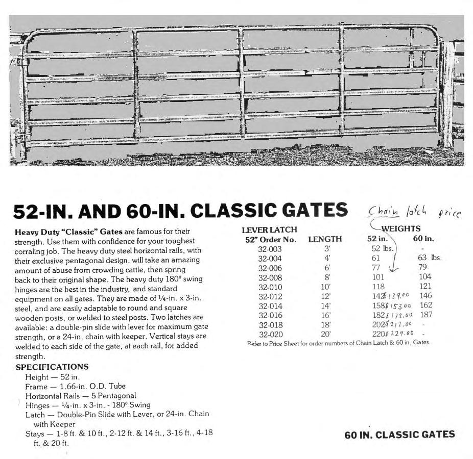
144
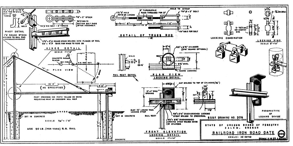
145

146

147
No. 6 December, Wisconsin s Forestry Best Management Practices for Water Quality Forest Roads
 No. 6 December, 1995 Wisconsin s Forestry Best Management Practices for Water Quality Forest Roads Steve Holaday, Wisconsin Dept. of Natural Resources, and Jeff Martin, Dept. of Forestry, UW-Madison BMPs
Warren Wagon Road Improvement Project McCall Ranger District, Payette National Forest Project Description
 Warren Wagon Road Improvement Project McCall Ranger District, Payette National Forest Project Description Introduction The analysis of the Warren Wagon Road Improvement Project is tiered to the 2003 Environmental
WEST VIRGINIA DIVISION OF FORESTRY STATE FOREST STANDARDS for LOGGING ROADS AND SKID TRAILS HAUL ROADS
 WEST VIRGINIA DIVISION OF FORESTRY STATE FOREST STANDARDS for LOGGING ROADS AND SKID TRAILS HAUL ROADS The objective of these specifications is to provide the construction requirements for haul roads and
3.5 Geometric Road Design
 3.5 Geometric Road Design The purpose of road design is to produce specifications for road construction by determining the optimum road geometry that will accommodate the design vehicle configuration for
Larimer County Land Use Code Section 5.8: Rural Land Use Process
 Larimer County Land Use Code Section 5.8: Rural Land Use Process 5.8.6 PRINCIPLES D. Development Standards 3. Engineering Standards and Guidelines for Roads and Drainage The following Standards and Guidelines
Table of Contents 5.1 GENERAL Overview Investigation and Engineering Information
 Table of Contents Section Page 5.1 GENERAL... 5.1-1 5.1.1 Overview... 5.1-1 5.1.2 Investigation and Engineering Information... 5.1-2 5.2 PRELIMINARY GEOTECHNCIAL REPORTS... 5.2-1 5.2.1 Preliminary Geotechnical
Mixed Conifer Working Group Meeting April 15, 2011 Water and Soil Resource Management Considerations
 Mixed Conifer Working Group Meeting April 15, 2011 Water and Soil Resource Management Considerations It is difficult to tie watershed health directly to mixed-conifer forests. Watersheds encompass a variety
Are you, as a woodland owner, expected
 Designing Woodland Roads EC 37 Revised June 202 Steve Bowers Are you, as a woodland owner, expected to perform certain engineering functions typically performed by engineers when they design roads? The
Are you, as a woodland owner, expected
 Designing Woodland Roads EC 37 Revised June 202 Steve Bowers Are you, as a woodland owner, expected to perform certain engineering functions typically performed by engineers when they design roads? The
Road Cards Appendix 2
 Appendix 2 Appendix 2 Introduction The following road cards are organized with new National Forest System (NFS) roads first, followed by reconstructed NFS roads second, and roads with bridge replacements
Temporary Watercourse Crossing: Culverts
 Temporary Watercourse Crossing: Culverts DRAINAGE CONTROL TECHNIQUE Low Gradient Velocity Control Short Term Steep Gradient Channel Lining Medium-Long Term Outlet Control Soil Treatment Permanent Symbol
Pole Creek Timber Salvage Project Specialist Report. Transportation. Introduction. Regulatory Framework / Management Direction
 Pole Creek Timber Salvage Project Specialist Report Transportation Donald Walker P.E. June 13, 2013 Introduction This report describes the effects to the transportation system from the Pole Creek Timber
Uinta-Wasatch-Cache National Forest Service. 857 W South Jordan Parkway MEMO
 Uinta-Wasatch-Cache National Forest Service 857 W South Jordan Parkway MEMO To: WBLU #1-3 Well, Platte Petroleum NEPA Project File From: Kim J. Martin, Forest Engineer revised by Renee Flanagan, AFE cc:
Meacham Creek Restoration Project
 Meacham Creek Restoration Project Meacham Creek Restoration Project Umatilla National Forest Walla Walla Ranger District Michael Rassbach, District Ranger Public Scoping Document Proposal Summary The Walla
FINDING OF NO SIGNIFICANT IMPACT OWL CREEK GRAVEL PIT EXPANSION U.S. FOREST SERVICE
 FINDING OF NO SIGNIFICANT IMPACT OWL CREEK GRAVEL PIT EXPANSION U.S. FOREST SERVICE OURAY RANGER DISTRICT OURAY COUNTY, COLORADO BACKGROUND The Owl Creek Gravel Pit, also known as the Spruce Ridge Pit,
Geo Wise STRATEGIC. File: 07CR-GWRP , March 2007
 Geo Wise STRATEGIC Engineering Forest Management Inc. File: 07CR-GWRP001 28, March 2007 Mr. Martin Buchanan, RFT Western Forest Products Ltd. 1334 Island Highway Campbell River, B.C. V9W 8C9 RE: RISK ASSESSMENT
PACIFIC REGION LOGGING PRACTICES
 Illustration 1 Page 1. PACIFIC REGION LOGGING PRACTICES OBJECTIVES The purpose of these guidelines is to maximize forest resource utilization on Indian lands within the Pacific Regional Office's jurisdiction,
Forest Recreation Management
 Forest Recreation Management 1 Forest Recreation Management Introduction...3 CONTENTS The Benefits of Guidelines...3 Considerations...4 Planning...5 Construction of Recreation Areas...6 Protecting Cultural
WEST VIRGINIA DIVISION OF FORESTRY STATE FOREST STANDARDS for LOGGING ROADS AND SKID TRAILS HAUL ROADS
 WEST VIRGINIA DIVISION OF FORESTRY STATE FOREST STANDARDS for LOGGING ROADS AND SKID TRAILS HAUL ROADS The objective of these specifications is to provide the construction requirements for haul roads and
Guidelines for Professional Services in. the Forest Sector Forest Roads
 Guidelines for Professional Services in the Forest Sector Forest Roads Photo June 2010 June 2012 TABLE OF CONTENTS 1 DEFINITIONS 1 2 INTRODUCTION 2 2.1 Purpose and Scope of Guidelines 2 2.2 Framework 3
ENVIRONMENTAL ASSESSMENT
 ENVIRONMENTAL ASSESSMENT, FINDING OF NO SIGNIFICANT IMPACT, and DECISION RECORD 1 ENVIRONMENTAL ASSESSMENT EA Number: OR-080-05-10 BLM Office: Marys Peak Resource Area, Salem District Office 1717 Fabry
ILLINOIS URBAN MANUAL PRACTICE STANDARD TEMPORARY STREAM CROSSING (no.) CODE 975. Source: Hey and Associates, Inc.
 CODE 975. Source: Hey and Associates, Inc.") ILLINOIS URBAN MANUAL PRACTICE STANDARD TEMPORARY STREAM CROSSING (no.) CODE 975 Source: Hey and Associates, Inc. DEFINITION A bridge or culvert crossing installed across a stream or watercourse for short-term
ILLINOIS URBAN MANUAL PRACTICE STANDARD TEMPORARY STREAM CROSSING (no.) CODE 975 Source: Hey and Associates, Inc. DEFINITION A bridge or culvert crossing installed across a stream or watercourse for short-term
BLOCKING AND FILLING SURFACE DRAINAGE DITCHES
 MINNESOTA WETLAND RESTORATION GUIDE BLOCKING AND FILLING SURFACE DRAINAGE DITCHES TECHNICAL GUIDANCE DOCUMENT Document No.: WRG 4A-1 Publication Date: 10/14/2015 Table of Contents Introduction Application
ALABAMA S BEST MANAGEMENT PRACTICES. Protection of Water Quality During Timber Harvesting
 ALABAMA S BEST MANAGEMENT PRACTICES Protection of Water Quality During Timber Harvesting Water Quality Responsibility Landowners and/or involved professional forestry practitioners such as: Forest resource
Operating and Reclamation Plan
 Operating and Reclamation Plan For sites in sensitive locations, additional information may be required. If more space is needed, attach additional sheets or use the blank sheet provided at the end of
Temporary Watercourse Crossing: Fords
 Temporary Watercourse Crossing: Fords DRAINAGE CONTROL TECHNIQUE Low Gradient Velocity Control Short Term Steep Gradient Channel Lining Medium-Long Term Outlet Control Soil Treatment Permanent [1] [1]
Minnesota Logger Education Program s Minnesota Master Logger Certification Program
 Minnesota Logger Education Program s Minnesota Master Logger Certification Program Program Participant Responsibility Areas Include: Area One: Area Two: Area Three: Area Four: Area Five: Area Six: Area
Timber Sale Appraisal More Cow Bell Sale FG W
 Timber Sale Appraisal Sale FG-341-2019-W00542-01 District: Forest Grove Date: January 24, 2019 Cost Summary Conifer Hardwood Total Gross Timber Sale Value $2,048,273.85 $10,164.42 $2,058,438.27 Project
MINNEHAHA CREEK WATERSHED DISTRICT BOARD OF MANAGERS REVISIONS PURSUANT TO MINNESOTA STATUTES 103D.341. Adopted April 24, 2014 Effective June 6, 2014
 MINNEHAHA CREEK WATERSHED DISTRICT BOARD OF MANAGERS REVISIONS PURSUANT TO MINNESOTA STATUTES 103D.341 Adopted April 24, 2014 Effective June 6, 2014 EROSION CONTROL RULE 1. POLICY. It is the policy of
Alabama s Best Management Practices
 Alabama s Best Management Practices Protection of Water Quality During Timber Harvesting Water Quality Responsibility Landowners and/or involved professional forestry practitioners such as: Forest resource
Draft Mine Closure Plan. 17 October 2018 Longlac & Geraldton
 Draft Mine Closure Plan 17 October 2018 Longlac & Geraldton Project Update Federal EA Decision report was issued on October 1 st and Provincial Report is expected to be issued Oct 22 nd Federal approval
Managing Forests for Water Quality: Forest Roads Barbara Daniels, Darren McAvoy, Mike Kuhns, Ron Gropp
 Rural/Conservation Forestry (pr) NR/FF/010 Managing Forests for Water Quality: Forest Roads Barbara Daniels, Darren McAvoy, Mike Kuhns, Ron Gropp This fact sheet discusses forest roads as they relate to
Forest Road Engineering Guidebook
 of BRITISH COLUMBIA Forest Road Engineering Guidebook Second edition June 2002 Ministry of Forests of BRITISH COLUMBIA Forest Road Engineering Guidebook Second edition June 2002 Authority Forest Practices
378 - POND NATURAL RESOURCES CONSERVATION SERVICE CONSERVATION PRACTICE SPECIFICATION I. SCOPE
 378-1 NATURAL RESOURCES CONSERVATION SERVICE CONSERVATION PRACTICE SPECIFICATION 378 - POND I. SCOPE The work shall consist of constructing an earthfill embankment and appurtenances to the lines, grades,
Stream Crossing Reconstruction on the Bog Dam Loop Road (FR15) Scoping Notice. Androscoggin Ranger District
 Scoping Notice. Androscoggin Ranger District") United States Department of Agriculture Forest Service White Mountain National Forest Stream Crossing Reconstruction on the Bog Dam Loop Road (FR15) Scoping Notice Androscoggin Ranger District Androscoggin
United States Department of Agriculture Forest Service White Mountain National Forest Stream Crossing Reconstruction on the Bog Dam Loop Road (FR15) Scoping Notice Androscoggin Ranger District Androscoggin
Forest Practices and the Hummingbird Creek Debris Flow
 Forest Practices and the Hummingbird Creek Debris Flow Complaint Investigation 990189 FPB/IRC/50 August 2001 Table of Contents The Investigation...1 Background...1 Relevant Legislation...3 Discussion...3
Projects must fall under one of the nine categories listed in Table 1.
 UNITED STATES DEPARTMENT OF COMMERCE National Oceanic and Atmospheric Administration NATIONAL MARINE FISHERIES SERVICE West Coast Region Snake Basin Office 800 Park Boulevard, Plaza IV, Suite 220 Boise,
ARTICLE IV: DEVELOPMENT STANDARDS GRADING AND DRAINAGE
 ARTICLE IV: DEVELOPMENT STANDARDS IV-63 410 GRADING AND DRAINAGE 410-1 General Provisions 410-1.1 All grading and drainage activities are to occur pursuant to the provisions of Chapter 14.12 of the Washington
COWLITZ COUNTY DEPARTMENT OF BUILDING AND PLANNING
 COWLITZ COUNTY DEPARTMENT OF BUILDING AND PLANNING GENERAL GRADING REQUIREMENTS GRADING STANDARDS Unless otherwise recommended in a soils engineering or engineering geology report, approved by the County,
CHAPTER 3 Environmental Guidelines for WATERCOURSE CROSSINGS GOVERNMENT OF NEWFOUNDLAND AND LABRADOR DEPARTMENT OF ENVIRONMENT AND LABOUR
 GOVERNMENT OF NEWFOUNDLAND AND LABRADOR DEPARTMENT OF ENVIRONMENT AND LABOUR CHAPTER 3 Environmental Guidelines for WATERCOURSE CROSSINGS WATER RESOURCES MANAGEMENT DIVISION Water Investigations Section
Risk = Hazard x Consequence
 Tolko Industries Ltd. Cariboo Woodlands Forest Stewardship Plan Major Amendment 26 Watershed Hydrology 1. Introduction: The Cariboo Chilcotin Land Use Plan (CCLUP) and current Tolko Forest Stewardship
Mechanical Site Preparation
 Mechanical Site Preparation 1 Mechanical Site Preparation Introduction...3 CONTENTS The Benefits of Guidelines...3 Considerations...5 Design Outcomes To Maintain Soil Productivity...6 Planning...7 Planning
Appendix A (Project Specifications) Patton Mill Fuel Break Project
 Patton Mill Fuel Break Project") Appendix A (Project Specifications) Patton Mill Fuel Break Project I. Proposed Actions: A. Construct a Fuel Break (approximately 5 miles, about 120 acres): The fuel break is located along a segment of
Appendix A (Project Specifications) Patton Mill Fuel Break Project I. Proposed Actions: A. Construct a Fuel Break (approximately 5 miles, about 120 acres): The fuel break is located along a segment of
DEPARTMENT OF ENVIRONMENTAL PROTECTION BUREAU OF MINING AND RECLAMATION. Coal Refuse Disposal - Site Selection
 DEPARTMENT OF ENVIRONMENTAL PROTECTION BUREAU OF MINING AND RECLAMATION DOCUMENT NUMBER: 563-2113-660 TITLE: Coal Refuse Disposal - Site Selection EFFECTIVE DATE: February 8, 1999 AUTHORITY: The Coal Refuse
DECISION MEMO OREGON DEPARTMENT OF TRANSPORTATION (ODOT) SAND SHED CINDER PIT EXPLORATION PROJECT
 SAND SHED CINDER PIT EXPLORATION PROJECT") DECISION MEMO OREGON DEPARTMENT OF TRANSPORTATION (ODOT) SAND SHED CINDER PIT EXPLORATION PROJECT USDA Forest Service Bend/Fort Rock Ranger District, Deschutes National Forest Deschutes County, Oregon
DECISION MEMO OREGON DEPARTMENT OF TRANSPORTATION (ODOT) SAND SHED CINDER PIT EXPLORATION PROJECT USDA Forest Service Bend/Fort Rock Ranger District, Deschutes National Forest Deschutes County, Oregon
14. Sustainable Forestry Principals
 14. Sustainable Forestry Principals Fish River Lakes Concept Plan Addendum Materials April 2018 14. SUSTAINABLE FORESTRY PRINCIPLES In response to our discussion with LUPC Staff and others on the topic
Attachment C Applicant s Proposed Mitigation Statement Alaska DOT&PF Northern Region Pilot Station Airport Relocation Project POA
 Attachment C Applicant s Proposed Mitigation Statement Alaska DOT&PF Northern Region Pilot Station Airport Relocation Project POA-2004-1223 Introduction This mitigation statement was prepared as an attachment
Decision Memo - Elko Grade Improvement Project, Jarbidge Ranger District, Elko County, Nevada
 Forest Service Humboldt-Toiyabe National Forest Ruby Mountains/Jarbidge Ranger Districts P. O. Box 246 Wells, NV 89835 File Code: 7730 Date: February 28, 2011 Route To: (7730) Subject: To: Decision Memo
TECHNICAL CONTENT PROPOSED STEEP SLOPE REGULATION
 1 TECHNICAL CONTENT PROPOSED STEEP SLOPE REGULATION Draft 2/08/10 (Revised 02-14-11,Revised 02-21-11, Revised 03-03-11, Revised 04-19-11, Revised 04-20-11, Revised 05-05-11, Revised 05-09-11). DEFINITIONS
Public Notice of Application for Permit
 US Army Corps of Engineers Alaska District ANCHORAGE Regulatory Division (1145) CEPOA-RD Post Office Box 6898 JBER, Alaska 99506-0898 Public Notice of Application for Permit PUBLIC NOTICE DATE: July 31,
Best Practices for Building High-Performance Resource Roads. Road Drainage. Developed by: The Roads and Infrastructure Group
 Best Practices for Building High-Performance Resource Roads Road Drainage Developed by: The Roads and Infrastructure Group THIS GUIDE IS INTENDED FOR EQUIPMENT OPERATORS CONSTRUCTION CONTRACTORS FIELD
GUIDE TO THE DEVELOPMENT OF A MINING AND RECLAMATION PLAN IN NEW BRUNSWICK
 PROVINCE OF NEW BRUNSWICK DEPARTMENT OF ENERGY AND RESOURCE DEVELOPMENT Minerals and Petroleum Development Branch GUIDE TO THE DEVELOPMENT OF A MINING AND RECLAMATION PLAN IN NEW BRUNSWICK Guide to the
Chapter 1 INTRODUCTION
 Chapter 1 Final SCDOT GEOTECHNICAL DESIGN MANUAL August 2008 Table of Contents Section Page 1.1 Introduction... 1 1.2 Preconstruction Division... 1 1.2.1 Regional Production Groups... 2 1.2.2 Preconstruction
ROADS AND STREAM CROSSINGS
 ROADS AND STREAM CROSSINGS The roads on your property need some maintenance. What do you need to know? Maintenance of roads on forestlands is a key forest practice. Because dirt or rocked roads exist
Maine s Land Use Regulations and Erosion Control Techniques
 Maine s Land Use Regulations and Erosion Control Techniques Protecting Maine s Air, Land and Water Colin Clark 441-7419 colin.a.clark@maine.gov Tom Gilbert 441-8031 thomas.gilbert@maine.gov Jim Rodrigue
SECTION SITE PREPARATION. A. PART A and DIVISION 1 of PART B are hereby made a part of this SECTION.
 SECTION 311000 PART 1 GENERAL 1.01 GENERAL REQUIREMENTS A. PART A and DIVISION 1 of PART B are hereby made a part of this SECTION. B. Examine all conditions as they exist at the project prior to submitting
Agency Organization Organization Address Information. Name United States Department of Agriculture
 Logo Department Name United States Department of Agriculture Agency Organization Organization Address Information Forest Service Pacific Northwest Region 1220 SW Third Avenue (97204) P.O. Box 3623 Portland,
CHARLES SOIL CONSERVATION DISTRICT COMPLIANCE AGREEMENT FOR THE STANDARD EROSION AND SEDIMENT CONTROL PLAN FOR FOREST HARVEST OPERATIONS
 CHARLES SOIL CONSERVATION DISTRICT COMPLIANCE AGREEMENT FOR THE STANDARD EROSION AND SEDIMENT CONTROL PLAN FOR FOREST HARVEST OPERATIONS I. Site Information A. Location (Include site map of harvest area)
EROSION AND SEDIMENTATION CONTROL SECTION 1 - GENERAL 1.1 SUMMARY
 31 25 00 EROSION AND SEDIMENTATION CONTROL SECTION 1 - GENERAL 1.1 SUMMARY A. Erosion and sedimentation control shall be provided by the Contractor for all areas of the site denuded or otherwise disturbed
PRELIMINARY DRAFT RULE LANGUAGE 8/28/2014 MNDNR SILICA SAND RECLAMATION Reclamation Plan Requirements
 PRELIMINARY DRAFT RULE LANGUAGE 8/28/2014 MNDNR SILICA SAND RECLAMATION Reclamation Plan Requirements PURPOSE OF THIS DOCUMENT: This document contains preliminary draft language related to silica sand
SECTION GENERAL EXCAVATION
 02210-1 of 11 SECTION 02210 GENERAL EXCAVATION 02210.01 GENERAL A. Description 1. General excavation shall include but not necessarily be limited to, excavation and grading for general site work, roadways,
Stormwater Erosion Control & Post-Construction Plans (Stormwater Quality Plans)
") Stormwater Erosion Control & Post-Construction Plans (Stormwater Quality Plans) Allen County Stormwater Plan Submittal Checklist The following items must be provided when applying for an Allen County Stormwater
Stormwater Erosion Control & Post-Construction Plans (Stormwater Quality Plans) Allen County Stormwater Plan Submittal Checklist The following items must be provided when applying for an Allen County Stormwater
Decision Memo for Juniper Ridge Opal Mine
 for USDA Forest Service Pacific Northwest Region Fremont-Winema National Forests Bly Ranger District Klamath County, Oregon Introduction The Bly Ranger District has received a proposed operating plan for
The Science Behind Forest Riparian Protection in the Pacific Northwest States By George Ice, Summer 2004
 The Science Behind Forest Riparian Protection in the Pacific Northwest States By George Ice, Summer 2004 Riparian buffers, streamside management zones, and similar measures are essential parts of forest
Nancy L. Young, Forester USAID/USDA Natural Resources Conservation Service
 Forest Management Nancy L. Young, Forester USAID/USDA Natural Resources Conservation Service Material translated by: Mohammadullah Karimi, Training & Liaison Officer Afghan Conservation Corps Managing
Audit of Forest Planning and Practices. West Fraser Mills Ltd. Skeena Sawmills Division Tree Farm Licence 41
 Audit of Forest Planning and Practices West Fraser Mills Ltd. Skeena Sawmills Division Tree Farm Licence 41 FPB/ARC/24 December 1999 Table of Contents A. Report from the Board B. Forest Practices Board
Single Family Residential Construction Erosion/Sediment Control Standards
 Single Family Residential Construction Erosion/Sediment Control Standards Introduction: This booklet contains standard plans and procedures sufficient for typical building construction. It is not intended
Model Riparian Buffer Ordinance.
 Model Riparian Buffer Ordinance. This is a sample riparian buffer ordinance written as an amendment to an existing zoning ordinance. This ordinance complies with the state minimum standards for river corridor
Erosion and Sediment Control Plan for a Timber Harvesting Operation
 3930-FM-WM0155 Rev. 7/2004 Erosion and Sediment Control Plan for a Timber Harvesting Operation 1. GENERAL INFORMATION A. Location Municipality B. Timber sale area = acres Date County C. Landowner Name
File Code: 1950 Date: September 13, 2017
 United States Department of Agriculture Forest Service Darby-Sula Ranger District 712 N. Main Street Darby, MT 59829 406-821-3913 File Code: 1950 Date: September 13, 2017 The Bitterroot National Forest
CATEGORICAL EXCLUSION WORKSHEET: RESOURCE CONSIDERATIONS
 CATEGORICAL EXCLUSION WORKSHEET: RESOURCE CONSIDERATIONS Developed Recreation/Trails, Wilderness & Roadless Jasper Mountain Priest Lake Ranger District Idaho Panhandle National Forest Description of the
Appendix B - Best Management Practices (BMPs)
") Appendix B - Best Management Practices (BMPs) Best Management Practices (BMPs) are the standard operating procedures used for the protection of water quality. They are not intended as mitigation measures.
Appendix B - Best Management Practices (BMPs) Best Management Practices (BMPs) are the standard operating procedures used for the protection of water quality. They are not intended as mitigation measures.
Ohio Department of Transportation Division of Production Management Office of Geotechnical Engineering. Geotechnical Bulletin
 Ohio Department of Transportation Division of Production Management Office of Geotechnical Engineering Geotechnical Bulletin GB 2 SPECIAL BENCHING AND SIDEHILL EMBANKMENT FILLS Geotechnical Bulletin GB2
Travel Management Final Rule Proposed Changes
 Travel Management Final Rule Proposed Changes 212.1 Definitions: Off-Highway Vehicle (OHV): Any motorized vehicle that drives on National Forest System Lands, including cars, trucks, motor homes, motorcycles
Impacts of Harvesting and Road Construction to Malakwa Creek
 Impacts of Harvesting and Road Construction to Malakwa Creek Complaint Investigation #16081 FPB/IRC/207 August 2017 Table of Contents Introduction... 1 The Complaint... 1 Background... 2 Investigation
CHAPTER 3 SCOPE SUMMARY
 CHAPTER 3 SCOPE SUMMARY GENERAL The SDDOT is an active member of AASHTO to share common national design standards for the state highway system. The AASHTO Task Force on Geometric Design has completed the
STAFF REPORT FOR POLICY PLAN AMENDMENT S10-CW-1CP
 STAFF REPORT FOR POLICY PLAN AMENDMENT S10-CW-1CP EXECUTIVE SUMMARY This Plan Amendment would serve to clarify policy guidance regarding circumstances under which proposals for disturbances to Environmental
COON CREEK WATERSHED DISTRICT PERMIT REVIEW
 16-054 Woodland Creek Wetland Banking Restoration Project, Page 1 of 6 COON CREEK WATERSHED DISTRICT PERMIT REVIEW MEETING DATE: August 22, 2016 AGENDA NUMBER: 11 FILE NUMBER: 16-054 ITEM: Woodland Creek
Packwood Hydroelectric Project. Summary of Engineering Needs for Roads Preliminary Results
 Packwood Hydroelectric Project Summary of Engineering Needs for Roads Preliminary Results Goals and Objectives Determine maintenance levels (USFS) Document current condition of roads Identify maintenance/reconstruction
Erosion Control Methods BY TRAVIS GODEAUX, NRCS ENGINEER
 Erosion Control Methods BY TRAVIS GODEAUX, NRCS ENGINEER Five Basic Rules for Preventing Common Erosion Problems 1 1.Protect bare soil surfaces. 2.Don t concentrate water flow unless absolutely necessary
CONSTRUCTION PLAN CHECKLIST
 CONSTRUCTION PLAN CHECKLIST The design engineer is responsible for ensuring that plans submitted for city review are in accordance with this checklist. It is requested that the executed checklist be submitted
APPENDIX N Guidance for Preparing/Reviewing CEQA Initial Studies and Environmental Impact Reports
 APPENDIX N N.1 Guidance for Preparing and Reviewing CEQA Initial Studies Step 1: Consider the Project Characteristics as Provided by the Project Applicant Review the project application and draft plan
VEGETATIVE, WATER, FISH AND WILDLIFE RESOURCES POLICIES
 VEGETATIVE, WATER, FISH AND WILDLIFE RESOURCES POLICIES The County will: GOALS AND OBJECTIVES 1.1 Conserve, Enhance, Protect, Maintain and Manage Vegetative, Water, Fish and Wildlife Resources Promote
SECTION 14 EMBANKMENT
 SECTION 14 EMBANKMENT 14.1 DESCRIPTION A. General: This work consists of constructing roadway embankments, including preparation of the areas upon which embankments are to be placed; the construction of
Nonmetallic Mining Reclamation & Operation Plan. Amendment No. 1 (Includes modifications for Wash Plant construction) DRAFT
 DRAFT") Nonmetallic Mining Reclamation & Operation Plan Amendment No. 1 (Includes modifications for Wash Plant construction) Mondovi Mine Town of Mondovi, Wisconsin Prepared for: Buffalo White Sand, LLC PO Box
Nonmetallic Mining Reclamation & Operation Plan Amendment No. 1 (Includes modifications for Wash Plant construction) Mondovi Mine Town of Mondovi, Wisconsin Prepared for: Buffalo White Sand, LLC PO Box
Chapter CONSTRUCTION SITE EROSION CONTROL
 Chapter 19.30 CONSTRUCTION SITE EROSION CONTROL Sections: 19.30.010 When required. 19.30.020 Definitions. 19.30.030 Technical Standards 19.30.040 Erosion and sediment control performance standards for
DECISION MEMO JASON MINE-BAT HABITAT IMPROVEMENT AND MINE CLOSURE Section 22, T. 13S., R. 2W. Union County, Illinois
 DECISION MEMO JASON MINE-BAT HABITAT IMPROVEMENT AND MINE CLOSURE Section 22, T. 13S., R. 2W. Union County, Illinois USDA Forest Service Mississippi Bluffs Ranger District, Shawnee National Forest Background
Storm Water Pollution Prevention Plan (SWP3) Checklist
 Checklist") . Summit Soil and Water Conservation District Storm Water Pollution Prevention Plan (SWP3) Checklist Modified from the Ohio EPA SWP3 Checklist (Revised January 2017) SITE NAME: REVIEWER: DATE RECEIVED:
. Summit Soil and Water Conservation District Storm Water Pollution Prevention Plan (SWP3) Checklist Modified from the Ohio EPA SWP3 Checklist (Revised January 2017) SITE NAME: REVIEWER: DATE RECEIVED:
Water Resources Program.
 POCKET GUIDE Water Resources Program http://tfsweb.tamu.edu/bmp Texas Forestry Best Management Practices Pocket Guide August 2017 This guide was financed in part (60%) by a 319 (h) grant from the U.S.
2014 Managed Forest Inspection Program
 2014 Managed Forest Inspection Program BACKGROUND The Managed Forest Council (Council) has a policy to inspect all managed forests at least once every five years, as well as to inspect new managed forests
APPENDIX A AQUATIC/RIPARIAN SPECIES AND HABITAT PROJECT DESIGN CRITERIA
 APPENDIX A AQUATIC/RIPARIAN SPECIES AND HABITAT PROJECT DESIGN CRITERIA Development of design criteria for aquatic and riparian species and habitats with treatments proposed within occupied or suitable
SITE C FIELD WORK FOR 2019
 January 2019 SITE C FIELD WORK FOR 2019 During the construction of Site C, BC Hydro will conduct environmental and engineering field work along the Peace River between the Williston Reservoir and the Alberta
Fire Management CONTENTS. The Benefits of Guidelines...3 Considerations...4
 Fire Management CONTENTS Fire Management 1 Introduction...3 The Benefits of Guidelines...3 Considerations...4 Planning...5 Burn Plan Development...5 Operational Activities...8 Pre-Ignition Activities...8
BALLAST PRODUCTION CURRY QUARRY
 BALLAST PRODUCTION CURRY QUARRY 2019-2020 INVITATION TO SITE VISIT OCOTBER 2018 SEPTEMBER 27, 2018 ALASKA RAILROAD CORPORATION 327 WEST SHIP CREEK AVENUE ANCHORAGE, ALASKA 99501 PROJECT DESCRIPTION & SCOPE
Appendix B Adaptive Management Strategy
 Adaptive Management Strategy This appendix identifies the adaptive management strategy that would be implemented as part of the proposed action. This strategy and the processes contained and described
Chapter MINERAL EXTRACTION AND MINING OPERATIONS
 Chapter 17.31 MINERAL EXTRACTION AND MINING OPERATIONS Sections: 17.31.010 Purpose 17.31.020 Procedure for Extraction and Rehabilitation Requests 17.31.030 Operation and Rehabilitation Standards for all
Green Thunder Regeneration and Commercial Thinning Harvest FINDING OF NO SIGNIFICANT IMPACT (FONSI)
") U.S. Department of Interior Bureau of Land Management Roseburg District, Oregon Green Thunder Regeneration and Commercial Thinning Harvest FINDING OF NO SIGNIFICANT IMPACT (FONSI) The Swiftwater Field
U.S. Department of Interior Bureau of Land Management Roseburg District, Oregon Green Thunder Regeneration and Commercial Thinning Harvest FINDING OF NO SIGNIFICANT IMPACT (FONSI) The Swiftwater Field
SECTION SITE GRADING. Part 1 - General Work Included Related Requirements Reference Standards...
 SECTION 02210 - SITE GRADING CONTENTS: Part 1 - General... 1 1.01 Work Included... 1 1.02 Related Requirements... 1 1.03 Reference Standards... 1 1.04 Quality Assurance... 1 1.05 Measurement and Payment...
Town of Friday Harbor PO Box 219 / Friday Harbor / WA / (360) / fax (360) /
 / fax (360) /") Town of Friday Harbor PO Box 219 / Friday Harbor / WA / 98250 (360) 378-2810 / fax (360) 378-5339 / www.fridayharbor.org LAND CLEARING, GRADING, OR FILLING PERMIT APPLICATION APPLICATION DATE GRD No. APPLICANT/FRANCHISE
Town of Friday Harbor PO Box 219 / Friday Harbor / WA / 98250 (360) 378-2810 / fax (360) 378-5339 / www.fridayharbor.org LAND CLEARING, GRADING, OR FILLING PERMIT APPLICATION APPLICATION DATE GRD No. APPLICANT/FRANCHISE
CCSD#1 Stormwater Standards
 SECTION 6 EROSION CONTROL STANDARDS 6.1 INTRODUCTION The policies of this section shall apply during construction and until permanent measures are in place following construction as described herein, unless