STORMWATER POLLUTION PREVENTION PLAN
|
|
|
- Warren Hall
- 6 years ago
- Views:
Transcription
1 STORMWATER POLLUTION PREVENTION PLAN for Dewitt Avenue S-Curve Roadway Realignment Project Spring Avenue to Origilia Lane Morgan Hill, California RISK LEVEL 2 Legally Responsible Person [LRP): Michael Murdter Director County of Santa Clara, Roads and Airports Department 101 Skyport Drive San Jose, CA Approved Signatory: Bernardine Caceres Project Manager County of Santa Clara, Roads and Airports Department. 101 Skyport Drive San Jose, CA Project Address: Dewitt Avenue From Spring Avenue to Origilia Lane Morgan Hill, California SWPPP Prepared by: Michael J. Freitas, P.E., QSD Freitas + Freitas Engineering and Planning Consultants, Inc Valencia Ave., A1 Aptos, CA SWPPP Preparation Date October 2014 Estimated Project Dates: Start of - April 2016 Completion of April 15, 2017
2 Table of Contents Contents Table of Contents ii Qualified SWPPP Developer... iv Legally Responsible Person...v Amendment Log vi Section 1 SWPPP Requirements Introduction Permit Registration Documents SWPPP Availability and Implementation SWPPP Amendments Retention of Records Required Non-Compliance Reporting Annual Report Changes to Permit CoveragE Notice of Termination... 5 SECTION 2 PROJECT INFORMATION Project and Site Description Site Description Location Probable Phasing Existing Conditions Geology and Groundwater Project Description Developed Condition PERMITS AND GOVERNING DOCUMENTS Stormwater Run-On from Offsite Areas Findings of the Site Sediment and Receiving Water Risk Determination Schedule Potential Activity and Pollutant Sources Identification of Non-Stormwater Discharges Required SWPPP Drawings Information SECTION 3 BEST MANAGEMENT PRACTICES Schedule for BMP Implementation Erosion and Sediment Control Erosion Control Sediment Controls Non-Stormwater Controls and Waste and Materials Management Non-Stormwater Controls Materials Management and Waste Management Post construction Stormwater Management Measures SECTION 4 BMP INSPECTION, MAINTENANCE AND RAIN EVENT ACTION PLANS BMP Inspection and Maintenance Rain Event Action Plans SECTION 5 TRAINING SWPPP Dewitt Avenue S-Curve Roadway Realignment Project Morgan Hill, California ii
3 SECTION 6 RESPONSIBLE PARTIES AND OPERATORS Responsible Parties Contractor List SECTION 7 CONSTRUCTION SITE MONITORING PROGRAM Purpose Applicability of Permit Requirements Risk Level Weather and Rain Event Tracking Monitoring Locations Safety and Monitoring Exemptions Visual Monitoring Water Quality Sampling and Analysis Active Treatment System Monitoring Bioassessment Monitoring Watershed Monitoring Option Quality Assurance and Quality Control Records Retention CSMP Attachment 1: Weather Reports CSMP Attachment 2: Monitoring Records CSMP Attachment 3: Example Forms CSMP Attachment 4: Field Meter Instructions CSMP Attachment 5: Supplemental Information Section 8 References Appendix A: Calculations Appendix B: SWPPP Drawings Appendix C: Permit Registration Documents Appendix D: SWPPP Amendment Certifications Appendix E: Submitted Changes to PRDs Appendix F: Schedule Appendix G: Activities, Materials Used, and Associated Pollutants Appendix H: CASQA Stormwater BMP Handbook Portal: Fact Sheets Appendix I: BMP Inspection Form Appendix J: Project Specific Rain Event Action Plan Template BWDID Number: 87 Predicted % chance of rain: Appendix K: Training Reporting Form Appendix L: Responsible Parties Appendix M: Contractors and Subcontractors Appendix N: Stormwater Pollution Prevention (C.3/E.12) Data Form Roads and Airports Department, County of Santa Clara Appendix O: General Permit SWPPP Dewitt Avenue S-Curve Roadway Realignment Project Morgan Hill, California iii
4 Qualified SWPPP Developer Approval and Certification of the Stormwater Pollution Prevention Plan Project Name: Dewitt Avenue S-Curve Roadway Realignment Project Spring Avenue To Origilia Lane Project Number/ID This Stormwater Pollution Prevention Plan and Attachments were prepared under my direction to meet the requirements of the California General Permit (SWRCB Orders No DWQ as amended by Order DWQ). I certify that I am a Qualified SWPPP Developer in good standing as of the date signed below. QSD Signature Michael J. Freitas QSD Name Michael J. Freitas Date 8/15/14 QSD Certificate Number Title and Affiliation CEO Freitas + Freitas Engineering and Planning Consultants, Inc. Telephone Number Fr8tus@aol.com SWPPP Dewitt Avenue S-Curve Roadway Realignment Project Morgan Hill, California iv
5 Legally Responsible Person Approval and Certification of the Stormwater Pollution Prevention Plan Project Name: Dewitt Avenue S-Curve Roadway Realignment Project Spring Avenue To Origilia Lane Project Number/ID I certify under penalty of law that this document and all Attachments were prepared under my direction or supervision in accordance with a system designed to assure that qualified personnel properly gather and evaluate the information submitted. Based on my inquiry of the person or persons who manage the system or those persons directly responsible for gathering the information, to the best of my knowledge and belief, the information submitted is, true, accurate, and complete. I am aware that there are significant penalties for submitting false information, including the possibility of fine and imprisonment for knowing violations." Legally Responsible Person Signature of Legally Responsible Person or Approved Signatory Date Bernardine Caceres Name of Legally Responsible Person or Approved Signatory Telephone Number SWPPP Dewitt Avenue S-Curve Roadway Realignment Project Morgan Hill, California v
6 Amendment Log Project Name: Dewitt Avenue S-Curve Roadway Realignment Project At Spring Avenue To Origilia Lane Project Number/ID The amendment to this SWPPP shall be prepared by a QSD retained by the Contractor. Amendment No. Date Brief Description of Amendment, include section and page number Prepared and Approved By Name: QSD# Name: QSD# Name: QSD# Name: QSD# Name: QSD# Name: QSD# Name: QSD# Name: QSD# Name: QSD# SWPPP Dewitt Avenue S-Curve Roadway Realignment Project Morgan Hill, California vi

7 Section 1 SWPPP Requirements 1.1 INTRODUCTION The Dewitt Avenue S-Curve Roadway Realignment Project At Spring Avenue To Origilia Lane project comprises approximately 4.5 acres and is located in the New Almaden area of Morgan Hill, California, Santa Clara County, California. The property is owned by County of Santa Clara Roads and Airports Department, County of Santa Clara. The projects location is shown on the SWPPP Drawings shown below and in Appendix B. Site This Stormwater Pollution Prevention Plan (SWPPP) is designed to comply with California s General Permit for Stormwater Discharges Associated with and Land Disturbance Activities (General Permit) Order No DWQ as amended by Order No DWQ (NPDES No. CAS000002) issued by the State Water Resources Control Board (State Water Board). This SWPPP has been prepared following the SWPPP Template provided on the California Stormwater Quality Association Stormwater Best Management Practice Handbook Portal: (CASQA, 2010). In accordance with the General Permit, Section XIV, this SWPPP is designed to address the following: Pollutants and their sources, including sources of sediment associated with construction, construction site erosion and other activities associated with construction activity are controlled; Where not otherwise required to be under a Regional Water Quality Control Board (Regional Water Board) permit, all non-stormwater discharges are identified and either eliminated, controlled, or treated; Site BMPs are effective and result in the reduction or elimination of pollutants in stormwater discharges and authorized non-stormwater discharges from construction activity to the Best Available Technology/Best Control Technology (BAT/BCT) standard; Design details as well as BMP controls for are complete, correct and shown in Appendix A and Appendix B. A complete description of the Rain Event Action Plan (REAP) is also included. SWPPP Dewitt Avenue S-Curve Roadway Realignment Project Morgan Hill, California 1
8 1.2 PERMIT REGISTRATION DOCUMENTS Required Permit Registration Documents (PRDs) shall be submitted to the State Water Board via the Stormwater Multi Application and Report Tracking System (SMARTS) by the Legally Responsible Person (LRP), or authorized personnel (i.e., Approved Signatory) under the direction of the LRP. The project-specific PRDs include: 1. Notice of Intent (NOI); 2. Risk Assessment ( Site Sediment and Receiving Water Risk Determination); 3. SWPPP Drawings; 4. Annual Fee; 5. Signed Certification Statement (LRP Certification is provided electronically with SMARTS PRD submittal); and 6. SWPPP. SWPPP Drawings can be found in Appendix B. A copy of the submitted PRDs shall also be kept in Appendix C along with the Waste Discharge Identification (WDID) confirmation. 1.3 SWPPP AVAILABILITY AND IMPLEMENTATION The discharger shall make the SWPPP available at the construction site during working hours (see Section 7.5 of CSMP for working hours) while construction is occurring and shall be made available upon request by a State or Municipal inspector. When the original SWPPP is retained by a crewmember in a construction vehicle and is not currently at the construction site, current copies of the BMPs and map/drawing will be left with the field crew and the original SWPPP shall be made available via a request by radio/telephone. (CGP Section XIV.C) The SWPPP shall be implemented concurrently with the start of ground disturbing activities. 1.4 SWPPP AMENDMENTS The General Permit requires that SWPPP be amended or revised by a QSD (Section XIV.A) and that the SWPPP include a listing of the date of initial preparation and the date of each amendment. Amendments must be signed by a QSD (Section VII.B.6). In addition, the General Permit specifies that the SWPPP shall be amended under the following circumstances: Within two business days (48 hours) after each qualifying rain event, dischargers shall conduct post rain event visual observations (inspections) to (1) identify whether BMPs were adequately designed, implemented, and effective, and (2) identify additional BMPs and revise the SWPPP accordingly. (General Permit, Attachment C, D, or E part I.3.G). This General Permit requires dischargers with NAL and NEL exceedances to immediately implement additional BMPs and revise their Stormwater Pollution Prevention Plans (SWPPPs) accordingly to either prevent pollutants and authorized non-stormwater discharges from contaminating stormwater, or to substantially reduce the pollutants to levels consistently below the NALs or NELs. (General Permit Section I Part H No. 57 and 59). Within 30 days of a reduction or increase in total disturbed acreage, the discharger shall electronically file revisions to the PRDs that include: SWPPP revisions, as appropriate (General Permit Section II Part C). Amendments must be logged into the SWPPP amendment log, in the front of the SWPPP. The SWPPP field copy shall be updated, applicable sheets replaced and/or include hand annotation of the change made to the text. Retain a copy of SWPPP Amendment certification in Appendix D. SWPPP Dewitt Avenue S-Curve Roadway Realignment Project Morgan Hill, California 2
9 The SWPPP should be revised when: If there is a General Permit violation. When there is a reduction or increase in total disturbed acreage (General Permit Section II Part C). BMPs do not meet the objectives of reducing or eliminating pollutants in stormwater discharges. Additionally, the SWPPP shall be amended when: There is a change in construction or operations which may affect the discharge of pollutants to surface waters, groundwater(s), or a municipal separate storm sewer system (MS4); When there is a change in the project duration that changes the project s risk level; or When deemed necessary by the QSD. The QSD has determined that the changes listed in Table 1.1 can be field determined by the QSP. All other changes shall be made by the QSD as formal amendments to the SWPPP. The following items shall be included in each amendment: Who requested the amendment; The location of proposed change; The reason for change; The original BMP proposed, if any; and The new BMP proposed. Amendment shall be logged at the front of the SWPPP and certification kept in Appendix D. The SWPPP text shall be revised replaced, and/or hand annotated as necessary to properly convey the amendment. SWPPP amendments must be made by a QSD. The following changes have been designated by the QSD as "to be field determined and constitute minor changes that the QSP may implement based on field conditions. SWPPP Dewitt Avenue S-Curve Roadway Realignment Project Morgan Hill, California 3
10 Table 1.1 List of Changes to be Field Determined Candidate changes for field location or determination by QSP (1) Increase quantity of an Erosion or Sediment Control Measure Relocate/Add stockpiles or stored materials Relocate or add toilets Relocate vehicle storage and/or fueling locations Relocate areas for waste storage Relocate water storage and/or water transfer location Check changes that can be field located or field determined by QSP Changes to access points (entrance/exits) Change type of Erosion or Sediment Control Measure Changes to location of erosion or sediment control Minor changes to schedule or phases Changes in construction materials (1) Any field changes not identified for field location or field determination by QSP must be approved by QSD retained by the Contractor 1.5 RETENTION OF RECORDS Paper or electronic records of documents required by this SWPPP shall be retained for a minimum of three years from the date generated or date submitted, whichever is later, for the following items: All materials included in this document. These records shall be available at the site until construction is complete. Records assisting in the determination of compliance with the general permit shall be made available within a reasonable time, to the regional water board, state water board or u.s. environmental protection agency (epa) upon request. Requests by the regional water board for retention of records for a period longer than three years shall be adhered to. 1.6 REQUIRED NON-COMPLIANCE REPORTING If a discharge violation occurs the QSP shall immediately notify the LRP and the LRP shall file a violation report electronically to the Regional Water Board within 30 days of identification of non-compliance using SMARTS. Corrective measures will be implemented immediately following the discharge or written notice of non-compliance from the Regional Water Board. Discharges and corrective actions will be documented on the NAL/NEL Exceedance Site Evaluation Report Form in CSMP Attachment 3 Example Forms. The report to the LRP and to the Regional Water Board will contain the following items: SWPPP Dewitt Avenue S-Curve Roadway Realignment Project Morgan Hill, California 4
11 The date, time, location, nature of operation and type of unauthorized discharge. The cause or nature of the notice or order. The control measures (BMPs) deployed before the discharge event, or prior to receiving notice or order. Reporting requirements for Numeric Action Levels (NALs) exceedances. The date of deployment and type of control measures (BMPs) deployed after the discharge event, or after receiving the notice or order, including additional measures installed or planned to reduce or prevent re-occurrence. 1.7 ANNUAL REPORT The General Permit requires that permittees prepare, certify, and electronically submit an Annual Report no later than September 1 st of each year. Reporting requirements are identified in Section XVI of the General Permit. Annual reports will be filed in SMARTS and in accordance with information required by the on-line forms. 1.8 CHANGES TO PERMIT COVERAGE The General Permit allows for the reduction or increase of the total acreage covered under the General Permit when: a portion of the project is complete and/or conditions for termination of coverage have been met; when ownership of a portion of the project is purchased by a different entity; or when new acreage is added to the project. Modified PRDs shall be filed electronically within 30 days of a reduction or increase in total disturbed area if a change in permit covered acreage is to be sought. The SWPPP shall be modified appropriately, shall be logged at the front of the SWPPP and cetrification of SWPPP amendments are to be kept in Appendix D. Updated PRDs submitted electronically via SMARTS can be found in Appendix E. 1.9 NOTICE OF TERMINATION A Notice of Termination (NOT) must be submitted electronically by the LRP via SMARTS to terminate coverage under the General Permit. The NOT must include a final SWPPP Drawings and representative photographs of the project site that demonstrate final stabilization has been achieved. The NOT shall be submitted within 90 days of completion of construction. The Regional Water Board will consider a construction site complete when the conditions of the General Permit, Section II.D have been met. SWPPP Dewitt Avenue S-Curve Roadway Realignment Project Morgan Hill, California 5


12 SECTION 2 PROJECT INFORMATION 2.1 PROJECT AND SITE DESCRIPTION Site Description The Dewitt Avenue S-Curve Roadway Realignment Project at Spring Avenue to Origilia Lane, Morgan Hill, California project site comprises approximately 4.5 acres and is located in the southwestern portion of Morgan Hill, California. The project site is located as shown on Figure 1 Location Map. The project is located at Latitude: 37 06' 45"N / Longitude: '39" W. Site The USGS Map is shown below as Figure 2 USGS Map. Figure 1 Location Map Figure 2 USGS Map SWPPP Dewitt Avenue S-Curve Roadway Realignment Project Morgan Hill, California 6

13 The work site is along an existing roadway. Work will realign about 1,700 lineal feet of the roadway and widen the existing roadway pavement. The work includes clearing and grubbing; removal and replacement of pavement; excavation and embankment site grading; construction of drainage ditches to handle runoff; and installation of erosion control measures and revegetation of the site Location The Dewitt Avenue S-Curve Roadway Realignment Project is located about 2 miles south westerly of the center of the City of Morgan Hill in Santa Clara County. The site is along the easterly foothills of the Santa Cruz Mountains Probable Phasing The Dewitt Avenue S-Curve Roadway Realignment Project is proposed to occur in a single phase. will typically occur on weekdays Existing Conditions The project site is located within the easterly foothills of the Santa Cruz Mountains. The surrounding areas are hillside grassland at about elevation 450 (msl). Surface drainage at the site flows both north towards Little Llagas Creek and south towards Edmundson Creek. Both Creeks are tributary to Llagas Creek and the Pajaro River flowing to Monterey Bay. Stormwater is conveyed through surface runoff. Stormwater discharges from the sites are not considered direct discharges, as defined by the State Water Board into Guadalupe River. Existing site topography, drainage patterns, and stormwater conveyance systems are shown in Appendix B. The project discharges to Pajaro River that is listed for water quality impairment on the most recent 303(d)-list for sediment TMDL and SPAWN, Cold & MIGRATORY categories Geology and Groundwater According the USDA-Soil Survey web service the following are the soil classes underlain the site surface: These are shown below on Figure 3: SWPPP Dewitt Avenue S-Curve Roadway Realignment Project Morgan Hill, California 7

14 xxxxxxxx Origilia Lane Figure 3 Project Area SWPPP Dewitt Avenue S-Curve Roadway Realignment Project Morgan Hill, California 8
15 2.1.6 Project Description Work will realign about 1,700 lineal feet of the roadway and widen the existing roadway pavement. The work includes clearing and grubbing; removal and replacement of pavement; excavation and embankment site grading; construction of drainage ditches to handle runoff; and installation of erosion control measures and revegetation of the site Developed Condition The construction site is about 4.5 acres in area counting pervious shoulder areas, roadside drainage ditches, hillside cut slopes and embankment fills The project will slightly change the rainfall runoff conditions. The existing 25 foot wide asphalt concrete roadway has an impervious area of about 1 acre. Therefore the existing percentage impervious area is about 22%. The roadway will be widened to 32 feet wide asphalt concrete roadway which has an impervious area of about 1.3 acres. This would be about 29% of the project site. The following Table 2.1 summarizes the construction sites. Table 2.1 Site Estimates site area 4.5 acres Percent impervious before construction 22% Runoff coefficient before construction 0.3 Percent impervious after construction 29% Runoff coefficient after construction PERMITS AND GOVERNING DOCUMENTS In addition to the General Permit, the following documents have been taken into account while preparing this SWPPP. Regional Water Board requirements, Central Coast Basin Plan requirements Contract Documents Air Quality Regulations and Permits Federal Endangered Species Act National Historic Preservation Act Requirements of the State Historic Preservation Office State of California Endangered Species Act Clean Water Act Section 401 Water Quality Certifications and 404 Permits CA Department of Fish and Game 1600 Streambed Alteration Agreement SWPPP Dewitt Avenue S-Curve Roadway Realignment Project Morgan Hill, California 9
16 2.3 STORMWATER RUN-ON FROM OFFSITE AREAS Run-on to the site is generated by point source discharges from upgradient developed land uses, creeks; streams or other water bodies that run through or discharge from the site; and upgradient non-point source discharges (dry weather and stormwater runoff. The stormwater runoff drainage area contributing to offsite run-on is estimated to be approximately 4.5 acres. The anticipated runoff coefficients are 0.3. The anticipated off-site run-on to the project site is estimated to be changed slightly and minimal. The General Permit requires that temporary BMPs be implemented to direct offsite run-on away from disturbed areas through the use of runoff controls. The following BMPs will be implemented by berms. These BMPs will be located as shown on the SWPPP Drawings in Appendix B. The off-site drainage areas and associated stormwater conveyance facilities or BMPs are shown in Appendix B. 2.4 FINDINGS OF THE CONSTRUCTION SITE SEDIMENT AND RECEIVING WATER RISK DETERMINATION A construction site risk assessment has been performed for the project and the resultant risk level is Risk Level 2. The risk level was determined through the use of the K, LS provided in SMARTS. The risk level is based on project duration, location, proximity to impaired receiving waters and soil conditions. A copy of the Risk Level determination submitted on SMARTS with the PRDs is included in Appendix C. Table 2.2 and Table 2.3 summarize the sediment and receiving water risk factors and document the sources of information used to derive the factors. Table 2.2 Summary of Sediment Risk RUSLE Factor Value Method for establishing value R 4.3 EPA s Online Calculator K 0.24 GIS Map RUSLE K factor LS 5.39 GIS Map RUSLE LS factor Total Predicted Sediment Loss (tons/acre) 5.56 Overall Sediment Risk Low Low Sediment Risk < 15 tons/ acre Medium Sediment Risk >= 15 and < 75 tons/acre High Sediment Risk >= 75 tons/acre SWPPP Dewitt Avenue S-Curve Roadway Realignment Project Morgan Hill, California 10
17 Table 2.3 Summary of Receiving Water Risk 303(d) Listed for Beneficial Uses of TMDL for Sediment Receiving Water Name Sediment Related COLD, SPAWN, and Related Pollutant Pollutant MIGRATORY Pajaro River Yes Yes Yes Overall Receiving Water Risk High Risk Level 2 sites are subject to both the narrative effluent limitations and numeric effluent standards. The narrative effluent limitations require stormwater discharges associated with construction activity to minimize or prevent pollutants in stormwater and authorized non-stormwater through the use of controls, structures and best management practices. Discharges from Risk Level 2 site are subject to NALs for ph and turbidity shown in Table 2-4. This SWPPP has been prepared to address Risk Level 2 requirements (General Permit Attachment D). Table 2.4 Numeric Action Levels Parameter ph Unit ph units Numeric Action Level Daily Average Lower NAL = 6.5 Upper NAL = 8.5 Turbidity NTU 250 NTU 2.5 CONSTRUCTION SCHEDULE The site sediment risk was determined based on construction taking place between April 15, 2016 and April 15, 2017 end date. Modification or extension of the schedule (start and end dates) may affect risk determination and permit requirements. The LRP shall contact the QSD if the schedule changes during construction to address potential impact to the SWPPP. The estimated schedule for planned work can be found in Appendix F. 2.6 POTENTIAL CONSTRUCTION ACTIVITY AND POLLUTANT SOURCES Appendix G includes a list of construction activities and associated materials that are anticipated to be used onsite. These activities and associated materials will or could potentially contribute pollutants, other than sediment, to stormwater runoff. The anticipated activities and associated pollutants were used in Section 3 to select the Best Management Practices for the project. Location of anticipated pollutants and associated BMPs are shown on the SWPPP Drawings in Appendix B. SWPPP Dewitt Avenue S-Curve Roadway Realignment Project Morgan Hill, California 11
18 For sampling requirements for non-visible pollutants associated with construction activity please refer to Section For a full and complete list of onsite pollutants, refer to the Material Safety Data Sheets (MSDS), which are retained onsite at the construction trailer. 2.7 IDENTIFICATION OF NON-STORMWATER DISCHARGES Non-stormwater discharges consist of discharges which do not originate from precipitation events. The General Permit provides allowances for specified non-stormwater discharges that do not cause erosion or carry other pollutants. Non-stormwater discharges into storm drainage systems or waterways, which are not authorized under the General Permit and listed in the SWPPP, or authorized under a separate NPDES permit, are prohibited. There are no non-stormwater discharges that are authorized from this project site. Authorized non-stormwater discharges will be managed with the stormwater and non-stormwater BMPs described in Section 3 of this SWPPP and will be minimized by the QSP. All construction activities at this site may result in unauthorized non-stormwater discharges. Steps will be taken, including the implementation of appropriate BMPs, to ensure that unauthorized discharges are eliminated, controlled, disposed, or treated on-site. Discharges of construction materials and wastes, such as fuel or paint, resulting from dumping, spills, or direct contact with rainwater or stormwater runoff, are also prohibited. No discharges have been authorized by regional NPDES permits. 2.8 REQUIRED SWPPP DRAWINGS INFORMATION The construction project s SWPPP Drawings(s) showing the project location, surface water boundaries, geographic features, construction site perimeter and general topography and other requirements identified in Attachment B of the General Permit is located in Appendix B. Table 2.6 identifies Map or Sheet Nos. where required elements are illustrated. SWPPP Dewitt Avenue S-Curve Roadway Realignment Project Morgan Hill, California 12
19 Table 2.6 Required Map Information Included on Map/Plan Sheet No. SWPPP-1 to 4 SWPPP-1 to 4 SWPPP-1 to 4 SWPPP-1 to 4 SWPPP-1 to 4 SWPPP-1 to 4 SWPPP-1 to 4 SWPPP-1 to 4 SWPPP-1 to 4 SWPPP-1 to 4 SWPPP-1 to 4 NA SWPPP-1 to 4 SWPPP-1 to 4 SWPPP-1 to 4 SWPPP-1 to 4 SWPPP-1 to 4 SWPPP-1 to 4 SWPPP-1 to 4 Required Element The project s surrounding area (vicinity) Site layout site boundaries Drainage areas Discharge locations Sampling locations Areas of soil disturbance (temporary or permanent) Active areas of soil disturbance (cut or fill) Locations of runoff BMPs Locations of erosion control BMPs Locations of sediment control BMPs ATS location (if applicable) Locations of sensitive habitats, watercourses, or other features which are not to be disturbed Locations of all post construction BMPs Waste storage areas Vehicle storage areas Material storage areas Entrance and Exits Fueling Locations SWPPP Dewitt Avenue S-Curve Roadway Realignment Project Morgan Hill, California 13
20 SECTION 3 BEST MANAGEMENT PRACTICES 3.1 SCHEDULE FOR BMP IMPLEMENTATION BMPs shall be implemented for all work as shown on Table 3.1 below: Table 3.1 BMP Implementation Schedule BMP Implementation Duration EC-1 Scheduling Prior to Entirety of Project EC-2 Preservation of Existing Vegetation Start of Entirety of Project EC-3 Hydraulic Mulch As work schedule requires Entirety of Project EC-4 Hydroseed As work schedule require Entirety of Project Erosion Control EC-6 Straw Mulch As work schedule require Entirety of Project EC-7 Geotextiles and Mats As work schedule require Entirety of Project EC-8 Wood Mulching As work schedule require Entirety of Project EC-9 Earth Dike & Drainage Swales As work schedule require Entirety of Project EC-12 Stream Bank Stabilization As work schedule require Entirety of Project EC-16 Non Vegetated Stabilization As work schedule require Entirety of Project WE-1 Wind Erosion Control As work schedule require Entirety of Project SE-1 Silt Fence As work schedule require Entirety of Project SE-2 Sediment Basin As work schedule require Entirety of Project SE-4 Check Dams As work schedule require Entirety of Project Sediment Control SE-5 Fiber Rolls SE-6 Gravel Bag Berm SE-7 Street Sweeping SE-9 Straw Bale Barrier As work schedule require As work schedule require As work schedule require As work schedule require Entirety of Project Entirety of Project Entirety of Project Entirety of Project TC-1 Stabilized Entrance and Exit TC-2 Stabilized Roadway As work schedule require As work schedule require Entirety of Project Entirety of Project SWPPP Dewitt Avenue S-Curve Roadway Realignment Project Morgan Hill, California 14
21 Table 3.1 Non-Stormwater Materials Management BMP Implementation Schedule BMP Implementation Duration TC-3 Entrance Outlet Tire Wash As work schedule require Entirety of Project NS-1 Water Conservation Practices As work schedule require Entirety of Project NS-2 Dewatering Operation NS-4 Temporary Stream Crossing NS-5 Clear Water Diversion NS-6 Illicit Connection- Illegal Discharge Connection NS-7 Potable Water Irrigation Discharge Detection NS-8 Vehicle and Equipment Cleaning NS-9 Vehicle and Equipment Fueling As work schedule require As work schedule require As work schedule require As work schedule require As work schedule require As work schedule require As work schedule require Entirety of Project Entirety of Project Entirety of Project Entirety of Project Entirety of Project Entirety of Project Entirety of Project NS-10 Vehicle and Equipment As work schedule require Entirety of Project Maintenance NS-12 Concrete Curing As work schedule require Entirety of Project NS-14 Material and Equipment Use Over As work schedule require Entirety of Project Water NS-15 Demolition Removal Adjacent to As work schedule require Entirety of Project Water Entirety of Project WM-01 Material Delivery and Storage As work schedule require WM-02 Material Use WM-03 Stockpile Management WM-04 Spill Prevention and Control WM-05 Solid Waste Management WM-06 Hazardous Waste Management WM-07 Contaminated Soil Management As work schedule require As work schedule require As work schedule require As work schedule require As work schedule require As work schedule require Entirety of Project Entirety of Project Entirety of Project Entirety of Project Entirety of Project Entirety of Project WM-08 Concrete Waste Management As work schedule require Entirety of Project WM-09 Sanitary-Septic Waste As work schedule require Entirety of Project Management WM-10 Liquid Waste Management As work schedule require Entirety of Project SWPPP Dewitt Avenue S-Curve Roadway Realignment Project Morgan Hill, California 15
22 3.2 EROSION AND SEDIMENT CONTROL Erosion and sediment controls are required by the General Permit to provide effective reduction or elimination of sediment related pollutants in stormwater discharges and authorized non-stormwater discharges from the Site. Applicable BMPs are identified in this section for erosion control, sediment control, tracking control, and wind erosion control Erosion Control Erosion control, also referred to as soil stabilization, consists of source control measures that are designed to prevent soil particles from detaching and becoming transported in stormwater runoff. Erosion control BMPs protect the soil surface by covering and/or binding soil particles. Erosion control is any source control practice that protects the soil surface and prevents soil particles from being detached by rainfall, flowing water, or wind. Erosion control is also referred to as soil stabilization. Erosion control consists of preparing the soil surface and implementing one or more of the BMPs shown in Table 3-1, to disturbed soil areas. All inactive soil-disturbed areas on the project site, and most active areas prior to the onset of rain, must be protected from erosion. Soil disturbed areas may include relatively flat areas as well as slopes. Typically, steep slopes and large exposed areas require the most robust erosion controls; flatter slopes and smaller areas still require protection, but less costly materials may be appropriate for these areas, allowing savings to be directed to the more robust BMPs for steep slopes and large exposed areas. To be effective, erosion control BMPs must be implemented at slopes and disturbed areas to protect them from concentrated flows. Some erosion control BMPs can be used effectively to temporarily prevent erosion by concentrated flows. These BMPs used alone or in combination, prevent erosion by intercepting, diverting, conveying, and discharging concentrated flows in a manner that prevents soil detachment and transport. Temporary concentrated flow conveyance controls may be required to direct run-on around or through the project in a non-erodible fashion. Limit use of plastic materials when more sustainable, environmentally friendly alternatives exist. If plastic used consider plastic resistant to solar degradation. Wind erosion control consists of applying water or other dust palliatives to prevent or alleviate dust nuisance. Wind erosion control best management practices (BMPs) are shown in Table 3-3. Be advised that many of the dust palliatives may contain compounds that have an unknown effect on stormwater. A sampling and analysis protocol to test for stormwater contamination from exposure to such compounds is required in the SWPPP. Sufficient erosion control materials shall be maintained onsite to allow implementation in conformance with this SWPPP. The following temporary erosion control BMP selection table indicates the BMPs that shall be implemented to control erosion on the construction site. Fact Sheets for temporary erosion control BMPs are provided in Appendix H. This construction project will implement the following practices to provide effective temporary and final erosion control during construction: 1. Preserve existing vegetation where required and when feasible. 2. The area of soil disturbing operations shall be controlled such that the Contractor is able to implement erosion control BMPs quickly and effectively. SWPPP Dewitt Avenue S-Curve Roadway Realignment Project Morgan Hill, California 16
23 3. Stabilize non-active areas within 14 days of cessation of construction activities or sooner if stipulated by local requirements. 4. Control erosion in concentrated flow paths by applying erosion control blankets, check dams, erosion control seeding or alternate methods. 5. Prior to the completion of construction, apply permanent erosion control to remaining disturbed soil areas. Table 3.2 Temporary Erosion Control BMPs CASQA Fact Sheet BMP Name Meets a Minimum Requirement (1) YES BMP Used NO If not used, state reason EC-1 Scheduling EC-2 Preservation of Existing Vegetation EC-3 Hydraulic Mulch (2) EC-4 Hydroseed (2) EC-5 Soil Binders (2) Not necessary EC-6 Straw Mulch (2) EC-7 Geotextiles and Mats (2) EC-8 Wood Mulching (2) Not necessary EC-9 Earth Dike and Drainage Swales (3) Not necessary EC-10 Velocity Dissipation Devices Not necessary EC-11 Slope Drains EC-12 Stream Bank Stabilization Not Necessary EC-14 Compost Blankets (2) Not necessary EC-15 Soil Preparation-Roughening Not necessary EC-16 Non-Vegetated Stabilization (2) Not necessary WE-1 Wind Erosion Control Alternate BMPs Used: None If used, state reason: (1) Applicability to a specific project shall be determined by the QSD. (2) The QSD shall ensure implementation of one of the minimum measures listed or a combination thereof to achieve and maintain the Risk Level requirements. (3) Run-on from offsite shall be directed away from all disturbed areas, diversion of offsite flows may require design/analysis by a licensed civil engineer and/or additional environmental permitting These temporary erosion control BMPs shall be implemented in conformance with the following guidelines and as outlined in the BMP Fact sheets provided in Appendix H. If there is a conflict between documents, the SWPPP Drawings will prevail over narrative in the body of the SWPPP or guidance in the BMP Fact Sheets. Site specific SWPPP Dewitt Avenue S-Curve Roadway Realignment Project Morgan Hill, California 17
24 details in the SWPPP Drawings prevail over standard details included in the SWPPP Drawings. The narrative in the body of the SWPPP prevails over guidance in the BMP Fact Sheets Sediment Controls Sediment controls are temporary or permanent structural measures that are intended to complement the selected erosion control measures and reduce sediment discharges from active construction areas. Sediment controls are designed to intercept and settle out soil particles that have been detached and transported by the force of water. Sediment control is any practice that traps soil particles after they have been detached and moved by rain, flowing water, or wind. Sediment control measures are usually passive systems that rely on filtering or settling the particles out of the water or wind that is transporting them. Sediment control BMPs includes those practices that intercept and slow or detain the flow of stormwater to allow sediment to settle and be trapped. Sediment control practices can consist of installing linear sediment barriers (such as silt fence, sandbag barrier, and straw bale barrier); providing fiber rolls, gravel bag berms, or check dams to break up slope length or flow; or constructing a sediment trap or sediment basin. Linear sediment barriers are typically placed below the toe of exposed and erodible slopes, down-slope of exposed soil areas, around soil stockpiles, and at other appropriate locations along the site perimeter. A few BMPs may control both sediment and erosion, for example, fiber rolls and sand bag barriers. BMPs are either erosion control (EC) or sediment control (SC) based on the BMPs most common and effective use. Sediment controls BMPs are most effective when used in conjunction with erosion control BMPs. The combination of erosion control and sediment control is usually the most effective means to prevent sediment from leaving the project site and potentially entering storm drains or receiving waters. Under most conditions, the General Permit requires that the discharger implement an effective combination of erosion and sediment controls. Under limited circumstances, sediment control, alone may be appropriate. For example, applying erosion control BMPs to an area where excavation, filling, compaction, or grading is currently under way may not be feasible when storms come unexpectedly. Use of sediment controls by establishing perimeter control on these areas may be appropriate and allowable under the General Permit provided the following conditions are met: 1. Weather monitoring is under way. 2. Inactive soil-disturbed areas have been protected with an effective combination of erosion and sediment controls. 3. An adequate supply of sediment control materials are stored on-site and there are sufficient forces of labor and equipment available to implement sediment controls on the active area prior to the onset of rain. 4. The SWPPP adequately describes the methods to protect active areas. The following sediment control BMP selection table indicates the BMPs that shall be implemented to control sediment on the construction site. Fact Sheets for temporary sediment control BMPs are provided in Appendix H. SWPPP Dewitt Avenue S-Curve Roadway Realignment Project Morgan Hill, California 18
25 Table 3.3 Temporary Sediment Control BMPs CASQA Fact Sheet BMP Name Meets a Minimum Requirement (1) YES SE-1 Silt Fence (2) (3) BMP used NO If not used, state reason SE-2 Sediment Basin Not necessary SE-3 Sediment Trap Not necessary SE-4 Check Dams SE-5 Fiber Rolls (2)(3) SE-6 Gravel Bag Berm (3) SE-7 Street Sweeping Not necessary SE-8 Sandbag Barrier SE-9 Straw Bale Barrier SE-10 Storm Drain Inlet Protection RL2&3 No inlets SE-11 ATS Not necessary SE-12 Temporary Silt Dike Not necessary SE-13 Compost Sock and Berm (3) Not necessary SE-14 Biofilter Bags (3) Not necessary TC-1 Stabilized Entrance and Exit TC-2 Stabilized Roadway TC-3 Entrance Outlet Tire Wash Alternate BMPs Used: None If used, state reason: (1) Applicability to a specific project shall be determined by the QSD (2) The QSD shall ensure implementation of one of the minimum measures listed or a combination thereof to achieve and maintain the Risk Level requirements (3) Risk Level 2 &3 shall provide linear sediment control along toe of slope, face of slope, and at the grade breaks of exposed slope These temporary sediment control BMPs shall be implemented in conformance with the following guidelines and in accordance with the BMP Fact Sheets provided in Appendix H. If there is a conflict between documents, the SWPPP Drawings will prevail over narrative in the body of the SWPPP or guidance in the BMP Fact Sheets. Site specific details in the SWPPP Drawings prevail over standard details included in the SWPPP Drawings. The narrative in the body of the SWPPP prevails over guidance in the BMP Fact Sheets. SWPPP Dewitt Avenue S-Curve Roadway Realignment Project Morgan Hill, California 19
26 3.3 NON-STORMWATER CONTROLS AND WASTE AND MATERIALS MANAGEMENT Non-Stormwater Controls Non-stormwater discharges into storm drainage systems or waterways, which are not authorized under the General Permit, are prohibited. Non-stormwater discharges for which a separate NPDES permit is required by the local Regional Water Board are prohibited unless coverage under the separate NPDES permit has been obtained for the discharge. The selection of non-stormwater BMPs is based on the list of construction activities with a potential for non-stormwater discharges identified in Section 2.7 of this SWPPP. The following non-stormwater control BMP selection table indicates the BMPs that shall be implemented to control sediment on the construction site. Fact Sheets for temporary non-stormwater control BMPs are provided in Appendix H. Table 3.4 Temporary Non-Stormwater BMPs CASQA Fact Sheet BMP Name Meets a Minimum Requiremen t BMP used YE S NO If not used, state reason NS-1 Water Conservation Practices NS-2 Dewatering Operation NS-3 Paving and Grinding Operation NS-4 Temporary Stream Crossing NS-5 Clear Water Diversion NS-6 NS-7 NS-8 NS-9 NS-10 Illicit Connection- Illegal Discharge Connection Potable Water Irrigation Discharge Detection Vehicle and Equipment Cleaning Vehicle and Equipment Fueling Vehicle and Equipment Maintenance SWPPP Dewitt Avenue S-Curve Roadway Realignment Project Morgan Hill, California 20 No paving on project NS-11 Pile Driving Operation No pile driving NS-12 Concrete Curing NS-13 Concrete Finishing Not necessary NS-14 Material and Equipment Use
27 Table 3.4 Temporary Non-Stormwater BMPs CASQA Fact Sheet NS-15 BMP Name Over Water Demolition Removal Adjacent to Water Meets a Minimum Requiremen t BMP used YE S NO If not used, state reason NS-16 Temporary Batch Plants Not necessary Alternate BMPs Used: None If used, state reason: Non-stormwater BMPs shall be implemented in conformance with the following guidelines and in accordance with the BMP Fact Sheets provided in Appendix H. If there is a conflict between documents, the SWPPP Drawings will prevail over narrative in the body of the SWPPP or guidance in the BMP Fact Sheets. Site specific details in the SWPPP Drawings prevail over standard details included in the SWPPP Drawings. The narrative in the body of the SWPPP prevails over guidance in the BMP Fact Sheets Materials Management and Waste Management Materials management control practices consist of implementing procedural and structural BMPs for handling, storing and using construction materials to prevent the release of those materials into stormwater discharges. The amount and type of construction materials to be utilized at the Site will depend upon the type of construction and the length of the construction period. The materials may be used continuously, such as fuel for vehicles and equipment, or the materials may be used for a discrete period, such as soil binders for temporary stabilization. Waste management consist of implementing procedural and structural BMPs for handling, storing and ensuring proper disposal of wastes to prevent the release of those wastes into stormwater discharges. Materials and waste management pollution control BMPs shall be implemented to minimize stormwater contact with construction materials, wastes and service areas; and to prevent materials and wastes from being discharged off-site. The primary mechanisms for stormwater contact that shall be addressed include: Direct contact with precipitation Contact with stormwater run-on and runoff Wind dispersion of loose materials Direct discharge to the storm drain system through spills or dumping Extended contact with some materials and wastes, such as asphalt cold mix and treated wood products, which can leach pollutants into stormwater. A list of construction activities is provided in Section 2.6. The following Materials and Waste Management BMP selection table indicates the BMPs that shall be implemented to handle materials and control construction site wastes SWPPP Dewitt Avenue S-Curve Roadway Realignment Project Morgan Hill, California 21
28 associated with these construction activities. Fact Sheets for Materials and Waste Management BMPs are provided in Appendix H. Table 3.5 Temporary Materials Management BMPs CASQA Fact Sheet BMP Name Meets a Minimum Requirement BMP used YES NO If not used, state reason WM-01 Material Delivery and Storage WM-02 Material Use WM-03 Stockpile Management WM-04 Spill Prevention and Control WM-05 Solid Waste Management WM-06 Hazardous Waste Management WM-07 Contaminated Soil Management WM-08 Concrete Waste Management WM-09 Sanitary-Septic Waste Management WM-10 Liquid Waste Management Alternate BMPs Used: None If used, state reason: Material management BMPs shall be implemented in conformance with the following guidelines and in accordance with the BMP Fact Sheets provided in Appendix H. If there is a conflict between documents, the SWPPP Drawings will prevail over narrative in the body of the SWPPP or guidance in the BMP Fact Sheets. Site specific details in the SWPPP Drawings prevail over standard details included in the SWPPP Drawings. The narrative in the body of the SWPPP prevails over guidance in the BMP Fact Sheets. SWPPP Dewitt Avenue S-Curve Roadway Realignment Project Morgan Hill, California 22
29 3.4 POST CONSTRUCTION STORMWATER MANAGEMENT MEASURES Post construction BMPs are permanent measures installed during construction, designed to reduce or eliminate pollutant discharges from the site after construction is completed. This site is located in an area subject to a Phase I or Phase II Municipal Separate Storm Sewer System (MS4) permit approved Stormwater Management Plan. Yes No The following source control post construction BMPs to comply with General Permit Section XIII.B and local requirements have been identified for the site: Hydroseeding with jute mat as shown on the SWPPP Drawings generally where cut and fill slopes are not paved over. Stone rock check dams along roadway side drainage ditches as shown on the SWPPP Drawings. SWPPP Dewitt Avenue S-Curve Roadway Realignment Project Morgan Hill, California 23
30 SECTION 4 BMP INSPECTION, MAINTENANCE AND RAIN EVENT ACTION PLANS 4.1 BMP INSPECTION AND MAINTENANCE The General Permit requires routine weekly inspections of BMPs, along with inspections before, during, and after qualifying rain events. A BMP inspection checklist must be filled out for inspections and maintained on-site with the SWPPP. The inspection checklist includes the necessary information covered in Section 7.6. A blank inspection checklist can be found in Appendix I. Completed checklists shall be kept in CSMP Attachment 2 Monitoring Records. BMPs shall be maintained regularly to ensure proper and effective functionality. If necessary, corrective actions shall be implemented within 72 hours of identified deficiencies and associated amendments to the SWPPP shall be prepared by the QSD. Specific details for maintenance, inspection, and repair of Site BMPs can be found in the BMP Factsheets in Appendix H. 4.2 RAIN EVENT ACTION PLANS The Rain Event Action Plans (REAP) is written document designed to be used as a planning tool by the QSP to protect exposed portions of project sites and to ensure that the discharger has adequate materials, staff, and time to implement erosion and sediment control measures. These measures are intended to reduce the amount of sediment and other pollutants that could be generated during the rain event. It is the responsibility of the QSP to be aware of precipitation forecast and to obtain and print copies of forecasted precipitation from NOAA s National Weather Service Forecast Office. The SWPPP includes REAP templates but the QSP will need to customize them for each rain event. Site-specific REAP templates for each applicable project phase can be found in Appendix J. The QSP shall maintain a paper copy of completed REAPs in compliance with the record retention requirements Section 1.5 of this SWPPP. Completed REAPs shall be maintained in Appendix J. The QSP will develop an event specific REAP 48 hours in advance of a precipitation event forecast to have a 50% or greater chance of producing precipitation in the project area. The REAP will be onsite and be implemented 24 hours in advance of any the predicted precipitation event. At minimum the REAP will include the following site and phase-specific information: 1. Site Address; 2. Calculated Risk Level 2 ; 3. Site Stormwater Manager Information including the name, company and 24-hour emergency telephone number; 4. Erosion and Sediment Control Provider information including the name, company and 24-hour emergency telephone number; 5. Stormwater Sampling Agent information including the name, company, and 24-hour emergency telephone number; 6. Activities associated with each construction phase; 7. Trades active on the construction site during each construction phase; 8. Trade contractor information; and 9. Recommended actions for each project phase. SWPPP Dewitt Avenue S-Curve Roadway Realignment Project Morgan Hill, California 24
31 SECTION 5 TRAINING Appendix L identifies the QSPs for the project. To promote stormwater management awareness specific for this project, periodic training of job-site personnel shall be included as part of routine project meetings (e.g. daily/weekly tailgate safety meetings), or task specific trainings as needed. The QSP shall be responsible for providing this information at the meetings, and subsequently completing the training logs shown in Appendix K, which identifies the site-specific stormwater topics covered as well as the names of site personnel who attended the meeting. Tasks may be delegated to trained employees by the QSP provided adequate supervision and oversight is provided. Training shall correspond to the specific task delegated including: SWPPP implementation; BMP inspection and maintenance; and record keeping. Documentation of training activities (formal and informal) is retained in SWPPP Appendix K. SWPPP Dewitt Avenue S-Curve Roadway Realignment Project Morgan Hill, California 25
32 SECTION 6 RESPONSIBLE PARTIES AND OPERATORS 6.1 RESPONSIBLE PARTIES Approved Signatory(ies) who are responsible for SWPPP implementation and have authority to sign permit-related documents [is/are] listed below. Written authorizations from the LRP for these individuals are provided in Appendix L. The Approved Signatory(ies) assigned to this project are listed on page V of this document. Name Title Phone Number QSPs identified for the project are selected by the Contractor and will be identified in Appendix L. The QSP shall have primary responsibility and significant authority for the implementation, maintenance and inspection/monitoring of SWPPP requirements. The QSP will be available at all times throughout the duration of the project. Duties of the QSP include but are not limited to: Implementing all elements of the General Permit and SWPPP, including but not limited to: o Ensuring all BMPs are implemented, inspected, and properly maintained; o Performing non-stormwater and stormwater visual observations and inspections; o Performing non-stormwater and storm sampling and analysis, as required; o Performing routine inspections and observations; o Implementing non-stormwater management, and materials and waste management activities such as: monitoring discharges; general Site clean-up; vehicle and equipment cleaning, fueling and maintenance; spill control; ensuring that no materials other than stormwater are discharged in quantities which will have an adverse effect on receiving waters or storm drain systems; etc.; The QSP may delegate these inspections and activities to an appropriately trained employee, but shall ensure adequacy and adequate deployment. Ensuring elimination of unauthorized discharges. The QSPs shall be assigned authority by the LRP to mobilize crews in order to make immediate repairs to the control measures. Coordinate with the Contractor(s) to assure all of the necessary corrections/repairs are made immediately and that the project complies with the SWPPP, the General Permit and approved plans at all times. Notifying the LRP or Authorized Signatory immediately of off-site discharges or other non-compliance events. SWPPP Dewitt Avenue S-Curve Roadway Realignment Project Morgan Hill, California 26
33 6.2 CONTRACTOR LIST Contractor To Be Determined Name: Title: Company: Address: Phone Number: Number (24/7): SWPPP Dewitt Avenue S-Curve Roadway Realignment Project Morgan Hill, California 27
34 SECTION 7 CONSTRUCTION SITE MONITORING PROGRAM 7.1 Purpose This Site Monitoring Program was developed to address the following objectives: 1. To demonstrate that the site is in compliance with the Discharge Prohibitions and Numeric Action Levels of the General Permit; 2. To determine whether non-visible pollutants are present at the construction site and are causing or contributing to exceedances of water quality objectives; 3. To determine whether immediate corrective actions, additional Best Management Practices (BMP) implementation, or SWPPP revisions are necessary to reduce pollutants in stormwater discharges and authorized non-stormwater discharges; 4. To determine whether BMPs included in the SWPPP and REAP are effective in preventing or reducing pollutants in stormwater discharges and authorized non-stormwater discharges. 7.2 Applicability of Permit Requirements This project has been determined to be a Risk Level 2 project. The General Permit identifies the following types of monitoring as being applicable for a Risk Level 2 project. Risk Level 2 Visual inspections of Best Management Practices (BMPs); Visual monitoring of the site related to qualifying storm events; Visual monitoring of the site for non-stormwater discharges; Sampling and analysis of construction site runoff for ph and turbidity; Sampling and analysis of construction site runoff for non-visible pollutants when applicable; and Sampling and analysis of non-stormwater discharges when applicable Weather and Rain Event Tracking Visual monitoring, inspections, and sampling requirements of the General Permit are triggered by a qualifying rain event. The General Permit defines a qualifying rain event as any event that produces ½ inch of precipitation. A minimum of 48 hours of dry weather will be used to distinguish between separate qualifying storm events Weather Tracking The QSP should daily consult the National Oceanographic and Atmospheric Administration (NOAA) for the weather forecasts. These forecasts can be obtained at Weather reports should be printed and maintained with the SWPPP in CSMP Attachment 1 Weather Reports Rain Gauges The QSP shall install one rain gauge on the project site. Locate the gauge in an open area away from obstructions such as trees or overhangs. Mount the gauge on a post at a height of 3 to 5 feet with the gauge extending several inches beyond the post. Make sure that the top of the gauge is level. Make sure the post is not in an area where rainwater can indirectly splash from sheds, equipment, trailers, etc. SWPPP Dewitt Avenue S-Curve Roadway Realignment Project Morgan Hill, California 28
35 The rain gauge(s) shall be read daily during normal site scheduled hours. The rain gauge should be read at approximately the same time every day and the date and time of each reading recorded. Log rain gauge readings in CSMP Attachment 1 Weather Records. Follow the rain gauge instructions to obtain accurate measurements. Once the rain gauge reading has been recorded, accumulated rain shall be emptied and the gauge reset. For comparison with the site rain gauge, the nearest appropriate governmental rain gauge(s) is located at Almaden Dam and Santa Clara Valley Water District office on Almaden Expressway. 7.4 Monitoring Locations Monitoring locations are shown on the SWPPP Drawings in Appendix B. Monitoring locations are described in the Sections 7.6 and 7.7. Whenever changes in the construction site might affect the appropriateness of sampling locations, the sampling locations shall be revised accordingly. All such revisions shall be implemented as soon as feasible and the SWPPP amended. Temporary changes that result in a one-time additional sampling location do not require a SWPPP amendment. 7.5 Safety and Monitoring Exemptions Safety practices for sample collection will be in accordance with the Contractors Health and Safety Plan submitted with the Contract Documents. A summary of the safety requirements that apply to sampling personnel is provided in the Contract Documents. This project is not required to collect samples or conduct visual observations (inspections) under the following conditions: During dangerous weather conditions such as flooding and electrical storms. Outside of scheduled site business hours. Scheduled site business hours are normal construction working days and hours as specified in the project Contract Documents. If monitoring (visual monitoring or sample collection) of the site is unsafe because of the dangerous conditions noted above then the QSP shall document the conditions for why an exception to performing the monitoring was necessary. The exemption documentation shall be filed in CSMP Attachment 2 Monitoring Records. 7.6 Visual Monitoring Visual monitoring includes observations and inspections. Inspections of BMPs are required to identify and record BMPs that need maintenance to operate effectively, that have failed, or that could fail to operate as intended. Visual observations of the site are required to observe storm water drainage areas to identify any spills, leaks, or uncontrolled pollutant sources. Table 7.1 identifies the required frequency of visual observations and inspections. Inspections and observations will be conducted at the locations identified in Section SWPPP Dewitt Avenue S-Curve Roadway Realignment Project Morgan Hill, California 29
36 Table 7.1 Summary of Visual Monitoring and Inspections Type of Inspection Frequency Routine Inspections BMP Inspections Weekly 1 BMP Inspections Tracking Control Non-Stormwater Discharge Observations Daily Quarterly during daylight hours Rain Event Triggered Inspections Site Inspections Prior to a Qualifying Event Within 48 hours of a qualifying event 2 BMP Inspections During an Extended Storm Event Every 24-hour period of a rainevent 2 Site Inspections Following a Qualifying Event Within 48 hours of a qualifying event 2 1 Most BMPs must be inspected weekly; those identified below must be inspected more frequently. 2 Inspections are only required during scheduled site operating hours. Note however, these inspections are required daily regardless of the amount of precipitation Routine Observations and Inspections Routine site inspections and visual monitoring are necessary to ensure that the project is in compliance with the requirements of the General Permit Routine BMP Inspections Inspections of BMPs are conducted to identify and record: BMPs that are properly installed; BMPs that need maintenance to operate effectively; BMPs that have failed; or BMPs that could fail to operate as intended Non-Stormwater Discharge Observations Each drainage area will be inspected for the presence of or indications of prior unauthorized and authorized nonstormwater discharges. Inspections will record: Presence or evidence of any non-stormwater discharge (authorized or unauthorized); Pollutant characteristics (floating and suspended material, sheen, discoloration, turbidity, odor, etc.); and Source of discharge. SWPPP Dewitt Avenue S-Curve Roadway Realignment Project Morgan Hill, California 30
37 7.6.2 Rain-Event Triggered Observations and Inspections Visual observations of the site and inspections of BMPs are required prior to a qualifying rain event; following a qualifying rain event, and every 24-hour period during a qualifying rain event. Pre-rain inspections will be conducted after consulting NOAA and determining that a precipitation event with a 50% or greater probability of precipitation has been predicted Visual Observations Prior to a Forecasted Qualifying Rain Event Within 48-hours prior to a qualifying event a stormwater visual monitoring site inspection will include observations of the following locations: Stormwater drainage areas to identify any spills, leaks, or uncontrolled pollutant sources; BMPs to identify if they have been properly implemented; Any stormwater storage and containment areas to detect leaks and ensure maintenance of adequate freeboard. BMP inspections and visual monitoring will be triggered by a NOAA quantitative predicted forecast (QPF) that indicates ½-inch or more of rain will occur in the project area BMP Inspections During an Extended Storm Event During an extended rain event BMP inspections will be conducted to identify and record: BMPs that are properly installed; BMPs that need maintenance to operate effectively; BMPs that have failed; or BMPs that could fail to operate as intended. If the construction site is not accessible during the rain event, the visual inspections shall be performed at all relevant outfalls, discharge points, downstream locations. The inspections should record any projected maintenance activities Visual Observations Following a Qualifying Rain Event Within 48 hours following a qualifying rain event (0.5 inches of rain) a stormwater visual monitoring site inspection is required to observe: Stormwater drainage areas to identify any spills, leaks, or uncontrolled pollutant sources; BMPs to identify if they have been properly designed, implemented, and effective; Need for additional BMPs; Any stormwater storage and containment areas to detect leaks and ensure maintenance of adequate freeboard; and Discharge of stored or contained rain water Visual Monitoring Procedures Visual monitoring shall be conducted by the QSP or staff trained by and under the supervision of the QSP. SWPPP Dewitt Avenue S-Curve Roadway Realignment Project Morgan Hill, California 31
38 The name(s) and contact number(s) of the site visual monitoring personnel are listed below and their training qualifications are provided in Appendix K. Assigned inspector: To Be Determined Alternate inspector: To Be Determined Contact phone: To Be Determined Contact phone: To Be Determined Stormwater observations shall be documented on the Visual Inspection Field Log Sheet (see CSMP Attachment 3 Example Forms ). BMP inspections shall be documented on the site specific BMP inspection checklist. Any photographs used to document observations will be referenced on stormwater site inspection report and maintained with the Monitoring Records in Attachment 2. The QSP shall within ten days of the inspection submit copies of the completed inspection report to the QSD. The completed reports will be kept in CSMP Attachment 2 Monitoring Records Visual Monitoring Follow-Up and Reporting Correction of deficiencies identified by the observations or inspections, including required repairs or maintenance of BMPs, shall be initiated and completed as soon as possible. If identified deficiencies require design changes, including additional BMPs, the implementation of changes will be initiated within 72 hours of identification and be completed as soon as possible. When design changes to BMPs are required, the SWPPP shall be amended to reflect the changes. Deficiencies identified in site inspection reports and correction of deficiencies will be tracked on the Inspection Field Log Sheet or BMP Inspection Report and shall be submitted to the QSP and shall be kept in CSMP Attachment 2 Monitoring Records. The QSP shall within 10 days of the inspection submit copies of the completed Inspection Field Log Sheet or BMP Inspection Report with the corrective actions to QSD. Results of visual monitoring must be summarized and reported in the Annual Report Visual Monitoring Locations The inspections and observations identified in Sections and will be conducted at the locations identified in this section. BMP locations are shown on the SWPPP Drawings in SWPPP Appendix B. There are two drainage area(s) on the project site and the contractor s yard, staging areas, and storage areas. Drainage area(s) are shown on the SWPPP Drawings in Appendix B and Table 7.2 identifies each drainage area by location. SWPPP Dewitt Avenue S-Curve Roadway Realignment Project Morgan Hill, California 32
39 Table 7.2 Site Drainage Areas Location No. Location 1 As shown on the SWPPP Drawings 2 As shown on the SWPPP Drawings There are no stormwater storage or containment areas on the project site. Table 7.3 Location No. None Stormwater Storage and Containment Areas None Location There are 3 discharge location(s) on the project site. Site stormwater discharge location(s) are shown on the SWPPP Drawings in Appendix B and Table 7.4 identifies each stormwater discharge location. Table 7.4 Site Stormwater Discharge Locations Location No. Location 1 As shown on the SWPPP Drawings 2 As shown on the SWPPP Drawings 3 As shown on the SWPPP Drawings 7.7 Water Quality Sampling and Analysis Sampling and Analysis Plan for Non-Visible Pollutants in Stormwater Runoff Discharges This Sampling and Analysis Plan for Non-Visible Pollutants describes the sampling and analysis strategy and schedule for monitoring non-visible pollutants in stormwater runoff discharges from the project site. Sampling for non-visible pollutants will be conducted when (1) a breach, leakage, malfunction, or spill is observed; and (2) the leak or spill has not been cleaned up prior to the rain event; and (3) there is the potential for discharge of non-visible pollutants to surface waters or drainage system. SWPPP Dewitt Avenue S-Curve Roadway Realignment Project Morgan Hill, California 33
40 The following construction materials, wastes, or activities, as identified in Section 2.6, are potential sources of nonvisible pollutants to stormwater discharges from the project. Storage, use, and operational locations are shown on the SWPPP Drawings in Appendix B. None The following existing site features, as identified in Section 2.6, are potential sources of non-visible pollutants to stormwater discharges from the project. Locations of existing site features contaminated with non-visible pollutants are shown on the SWPPP Drawings in Appendix B. None The following soil amendments have the potential to change the chemical properties, engineering properties, or erosion resistance of the soil and will be used on the project site. Locations of soil amendment application are shown on the SWPPP Drawings in Appendix B. None The project has the potential to receive stormwater run-on from the following locations with the potential to contribute non-visible pollutants to stormwater discharges from the project. Locations of such run-on to the project site are shown on the SWPPP Drawings in Appendix B. Upstream Tributary Areas of Little Llagas and Edmundson Creeks Sampling Schedule Samples for the potential non-visible pollutant(s) and a sufficiently large unaffected background sample shall be collected during the first two hours of discharge from rain events that result in a sufficient discharge for sample collection. Samples shall be collected during the site s scheduled hours and shall be collected regardless of the time of year and phase of the construction. Collection of discharge samples for non-visible pollutant monitoring will be triggered when any of the following conditions are observed during site inspections conducted prior to or during a rain event. Materials or wastes containing potential non-visible pollutants are not stored under watertight conditions. Watertight conditions are defined as (1) storage in a watertight container, (2) storage under a watertight roof or within a building, or (3) protected by temporary cover and containment that prevents stormwater contact and runoff from the storage area. Materials or wastes containing potential non-visible pollutants are stored under watertight conditions, but (1) a breach, malfunction, leakage, or spill is observed, (2) the leak or spill is not cleaned up prior to the rain event, and (3) there is the potential for discharge of non-visible pollutants to surface waters or a storm drain system. A construction activity, including but not limited to those in Section 2.6, with the potential to contribute non-visible pollutants (1) was occurring during or within 24 hours prior to the rain event, (2) BMPs were SWPPP Dewitt Avenue S-Curve Roadway Realignment Project Morgan Hill, California 34
41 observed to be breached, malfunctioning, or improperly implemented, and (3) there is the potential for discharge of non-visible pollutants to surface waters or a storm drain system. Soil amendments that have the potential to change the chemical properties, engineering properties, or erosion resistance of the soil have been applied, and there is the potential for discharge of non-visible pollutants to surface waters or a storm drain system. Stormwater runoff from an area contaminated by historical usage of the site has been observed to combine with stormwater runoff from the site, and there is the potential for discharge of non-visible pollutants to surface waters or a storm drain system Sampling Locations Sampling locations are based on proximity to planned non-visible pollutant storage, occurrence or use; accessibility for sampling, and personnel safety. Planned non-visible pollutant sampling locations are shown on the SWPPP Drawings in Appendix B and include the locations identified in Table 7.5 through Two sampling location(s) on the project site and the contractor s yard have been identified for the collection of samples of runoff from planned material and waste storage areas and areas where non-visible pollutant producing construction activities are planned. Table 7.6 Non-Visible Pollutant Sample Locations Contractors Yard Sample Location Number Sample Location Description 1 As shown on the SWPPP Drawings 2 As shown on the SWPPP Drawings Two sampling locations have been identified for the collection of samples of runoff from drainage areas where soil amendments will be applied that have the potential to affect water quality. Table 7.7 Non-Visible Pollutant Sample Locations Soil Amendment Areas Sample Location Number Sample Location 1 As shown on the SWPPP Drawings 2 As shown on the SWPPP Drawings Two sampling locations have been identified for the collection of samples of runoff from drainage areas contaminated by historical usage of the site. SWPPP Dewitt Avenue S-Curve Roadway Realignment Project Morgan Hill, California 35
42 Table 7.8 Non-Visible Pollutant Sample Locations Areas of Historical Contamination Sample Location Number Sample Location 1 As shown on the SWPPP Drawings 2 As shown on the SWPPP Drawings One sampling location(s) has been identified for the collection of an uncontaminated sample of runoff as a background sample for comparison with the samples being analyzed for non-visible pollutants. This location(s) was selected such that the sample will not have come in contact with the operations, activities, or areas identified in Section or with disturbed soils areas. Table 7.9 Non-Visible Pollutant Sample Locations Background (Unaffected Sample) Sample Location Number Sample Location 1 As shown on the SWPPP Drawings One sampling locations have been identified for the collection of samples of run-on to the project site. Run-on from these locations has the potential to combine with discharges from the site being sampled for non-visible pollutants. These samples are intended to identify potential sources of non-visible pollutants that originate off the project site. Table 7.10 Non-Visible Pollutant Sample Locations Site Run-On Sample Location Number Sample Location 1 As shown on the SWPPP Drawings If a stormwater visual monitoring site inspection conducted prior to or during a storm event identifies the presence of a material storage, waste storage, or operations area with spills or the potential for the discharge of non-visible pollutants to surface waters or a storm drain system that is at a location not listed above and has not been identified on the SWPPP Drawings, sampling locations will be selected by the QSP using the same rationale as that used to identify planned locations. Non-visible pollutant sampling locations shall be identified by the QSP on the pre-rain event inspection form and/or Rain Event Action Plan prior to a forecasted qualifying rain event Monitoring Preparation Non-visible pollutant samples will be collected by: Contractor Yes No SWPPP Dewitt Avenue S-Curve Roadway Realignment Project Morgan Hill, California 36
43 Consultant Yes No Laboratory Yes No Samples on the project site will be collected by the following contractor sampling personnel: Name/Telephone Number: Alternate(s)/Telephone Number: To Be Determined To Be Determined An adequate stock of monitoring supplies and equipment for monitoring non-visible pollutants will be available on the project site prior to a sampling event. Monitoring supplies and equipment will be stored in a cool temperature environment that will not come into contact with rain or direct sunlight. Sampling personnel will be available to collect samples in accordance with the sampling schedule. Supplies maintained at the project site will include, but are not limited to, clean powder-free nitrile gloves, sample collection equipment, coolers, appropriate number and volume of sample bottles, identification labels, re-sealable storage bags, paper towels, personal rain gear, ice, and Effluent Sampling Field Log Sheets and Chain of Custody (CoC) forms, which are provided in CSMP Attachment 3 Example Forms. Samples on the project site will be collected by the following: To Be Determined: Company Name: To Be Determined Street Address: City, State Zip: Telephone Number: Point of Contact: Name of Sampler(s): Name of Alternate(s): The QSP or his/her designee will contact To Be Determined 24 hours prior to a predicted rain event or for an unpredicted event, as soon as a rain event begins if one of the triggering conditions is identified during an inspection to ensure that adequate sample collection personnel and supplies for monitoring non-visible pollutants are available and will be mobilized to collect samples on the project site in accordance with the sampling schedule Analytical Constituents Table 7.11 lists the specific sources and types of potential non-visible pollutants on the project site and the water quality indicator constituent(s) for that pollutant. SWPPP Dewitt Avenue S-Curve Roadway Realignment Project Morgan Hill, California 37
44 Table 7.11 Potential Non-Visible Pollutants and Water Quality Indicator Constituents Pollutant Source Pollutant Water Quality Indicator Constituent Concrete Work Ash, slag, sand ph, Al, Ca, Va, Zn, Grading Contaminated soil Check with laboratory Landscaping Pesticides/Herbicides See label and check with laboratory Landscaping Fertilizers TKN, NO 3, BOD, COD, DOC, Sulfate, NH 3, Phosphate, Potassium Landscaping Vegetative stockpiles BOD Portable Toilets Sanitary Waste BOD, Total/Fecal coliform Pipeline Utility Line Testing Residual chlorine Vehicle and Equipment Batteries Sulfuric acid, Pb, ph Sample Collection Samples of discharge shall be collected at the designated non-visible pollutant sampling locations shown on the SWPPP Drawings in Appendix B or in the locations determined by observed breaches, malfunctions, leakages, spills, operational areas, soil amendment application areas, and historical site usage areas that triggered the sampling event. Grab samples shall be collected and preserved in accordance with the methods identified in the Table 7.12 Sample Collection, Preservation and Analysis for Monitoring Non-Visible Pollutants provided in Section Only the QSP, or personnel trained in water quality sampling under the direction of the QSP shall collect samples. Sample collection and handling requirements are described in Section Sample Analysis Samples shall be analyzed using the analytical methods identified in the Table Samples will be analyzed by: To Be Determined Laboratory Name: Street Address: City, State Zip: Telephone Number: Point of Contact: To Be Determined ELAP Certification Number: SWPPP Dewitt Avenue S-Curve Roadway Realignment Project Morgan Hill, California 38
45 Samples will be delivered to the laboratory by: To Be Determined Driven by Contractor Yes No Picked up by Laboratory Courier Yes No Shipped Yes No Table 7.12 Sample Collection, Preservation and Analysis for Monitoring Non-Visible Pollutants Constituent Analytical Method Minimu m Sample Volume Sample Container s Sample Preservatio n Reportin g Limit Maximu m Holding Time Notes: Data Evaluation and Reporting The QSP shall complete an evaluation of the water quality sample analytical results. SWPPP Dewitt Avenue S-Curve Roadway Realignment Project Morgan Hill, California 39
46 Runoff/downgradient results shall be compared with the associated upgradient/unaffected results and any associated run-on results. Should the runoff/downgradient sample show an increased level of the tested analyte relative to the unaffected background sample, which cannot be explained by run-on results, the BMPs, site conditions, and surrounding influences shall be assessed to determine the probable cause for the increase. As determined by the site and data evaluation, appropriate BMPs shall be repaired or modified to mitigate discharges of non-visible pollutant concentrations. Any revisions to the BMPs shall be recorded as an amendment to the SWPPP. The General Permit prohibits the storm water discharges that contain hazardous substances equal to or in excess of reportable quantities established in 40 C.F.R and The results of any non-stormwater discharge results that indicate the presence of a hazardous substance in excess of established reportable quantities shall be immediately reported to the Regional Water Board and other agencies as required by 40 C.F.R and Results of non-visible pollutant monitoring shall be reported in the Annual Report Sampling and Analysis Plan for ph and Turbidity in Stormwater Runoff Discharges Sampling and analysis of runoff for ph and turbidity is required for this project. This Sampling and Analysis Plan describes the strategy for monitoring turbidity and ph levels of stormwater runoff discharges from the project site and run-on that may contribute to an exceedance of a Numeric Action Level (NAL). Samples for turbidity will be collected from all drainage areas with disturbed soil areas and samples for ph will be collected from all drainage areas with a high risk of ph discharge Sampling Schedule Stormwater runoff samples shall be collected for turbidity from all qualifying rain events that result in a discharge from the project site. At minimum, turbidity samples will be collected from each site discharge location draining a disturbed area. A minimum of three samples will be collected per day of discharge during a qualifying event. Samples should be representative of the total discharge from the project each day of discharge during the qualifying event. Typically representative samples will be spaced in time throughout the daily discharge event. Stormwater runoff samples shall be collected for ph from all qualifying rain events that result in a discharge from the project site. At minimum, ph samples will be collected from each site discharge location during project phases and drainage areas with a high risk of ph discharge. A minimum of three samples will be collected per day of discharge during a qualifying event. Samples should be representative of the total discharge from the location each day of discharge during the qualifying event. Typically representative samples will be spaced in time throughout the daily discharge event. Stored or collected water from a qualifying storm event when discharged shall be tested for turbidity and ph (when applicable). Stored or collected water from a qualifying event may be sampled at the point it is released from the storage or containment area or at the site discharge location. Run-on samples shall be collected whenever the QSP identifies that run-on has the potential to contribute to an exceedance of a NAL. SWPPP Dewitt Avenue S-Curve Roadway Realignment Project Morgan Hill, California 40
47 Sampling Locations Sampling locations are based on the site runoff discharge locations and locations where run-on enters the site; accessibility for sampling; and personnel safety. Planned ph and turbidity sampling locations are shown on the SWPPP Drawingss in Appendix B and include the locations identified in Table 7.13 and Table Four sampling location(s) on the project site and the contractor s yard have been identified for the collection of runoff samples. Table 7.13 also provides an estimate of the site s area that drains to each location. Table 7.13 Turbidity and ph Runoff Sample Locations Sample Location Number Sample Location 1 As shown on SWPPP Drawings 2 As shown on SWPPP Drawings 3 As shown on SWPPP Drawings 4 As shown on SWPPP Drawings Four sampling locations have been identified for the collection of run-on samples where the run-on has the potential to contribute to an exceedance of a NAL. Table 7.14 Turbidity and ph Run-On Sample Locations Sample Location Number Sample Location 1 As shown on SWPPP Drawings 2 As shown on SWPPP Drawings 3 As shown on SWPPP Drawing 4 As shown on SWPPP Drawing The project does not receive run-on with the potential to exceed NALs or NELs Monitoring Preparation Turbidity and ph samples will be collected and analyzed by: To Be Determined Contractor Yes No Consultant Yes No Laboratory Yes No SWPPP Dewitt Avenue S-Curve Roadway Realignment Project Morgan Hill, California 41
48 Samples on the project site will be collected by the following contractor sampling personnel: Name/Telephone Number: Alternate(s)/Telephone Number: To Be Determined To Be Determined An adequate stock of monitoring supplies and equipment for monitoring turbidity and will be available on the project site prior to a sampling event. Monitoring supplies and equipment will be stored in a cool temperature environment that will not come into contact with rain or direct sunlight. Sampling personnel will be available to collect samples in accordance with the sampling schedule. Supplies maintained at the project site will include, but are not limited to, field meters, extra batteries; clean powder-free nitrile gloves, sample collection equipment, appropriate sample containers, paper towels, personal rain gear, and Effluent Sampling Field Log Sheets and CoC forms provided in CSMP Attachment 3 Example Forms. The contractor will obtain and maintain the field testing instruments, as identified in Section , for analyzing samples in the field by contractor sampling personnel. Samples on the project site will be collected by the following To Be Determined: Company Name: To Be Determined Street Address: City, State, Zip: Telephone Number: Point of Contact: Name of Sampler(s): Name of Alternate(s): The QSP or his/her designee will contact To Be Determined 24 hours prior to a predicted rain event or for an unpredicted event, as soon as a rain event begins to ensure that adequate sample collection personnel, supplies for monitoring ph and turbidity are available and will be mobilized to collect samples on the project site in accordance with the sampling schedule Field Parameters Samples shall be analyzed for the constituents indicated in the table below Sample Collection, and Analysis for Monitoring Turbidity and ph. Table 7.15 Sample Collection and Analysis for Monitoring Turbidity and ph Parameter Test Method Minimum Sample Volume (1) Sample Collection Container Type Detection Limit (minimum) SWPPP Dewitt Avenue S-Curve Roadway Realignment Project Morgan Hill, California 42
49 Table 7.15 Sample Collection and Analysis for Monitoring Turbidity and ph Parameter Test Method Minimum Sample Volume (1) Sample Collection Container Type Detection Limit (minimum) Turbidity Field meter/probe with calibrated portable instrument 500 ml Polypropylene or Glass (Do not collect in meter sample cells) 1 NTU ph Field meter/probe with calibrated portable instrument or calibrated ph test kit 100 ml Polypropylene 0.2 ph units Notes: 1 Minimum sample volume recommended. Specific volume requirements will vary by instrument; check instrument manufacturer instructions. L Liter ml Milliliter NTU Nephelometric Turbidity Unit Sample Collection Samples of discharge shall be collected at the designated runoff and run-on sampling locations shown on the SWPPP Drawings in Appendix B. Run-on samples shall be collected within close proximity of the point of run-on to the project. Only personnel trained in water quality sampling and field measurements working under the direction of the QSP shall collect samples. Sample collection and handling requirements are described in Section Field Measurements Samples collected for field analysis, collection, analysis and equipment calibration shall be in accordance with the field instrument manufacturer s specifications. Immediately following collection, samples for field analysis shall be tested in accordance with the field instrument manufacturer s instructions and results recorded on the Effluent Sampling Field Log Sheet. The field instrument(s) listed in Table 7.16 will be used to analyze the following constituents: Table 7.16 Field Instruments Field Instrument (Manufacturer and Model) Constituent To Be Determined To Be Determined ph Turbidity SWPPP Dewitt Avenue S-Curve Roadway Realignment Project Morgan Hill, California 43
50 The manufacturers instructions are included in CSMP Attachment 4 Field Meter Instructions. The Contractor s field sampling staff shall review the instructions prior to each sampling event and follow the instructions in completing measurement of the samples. The instrument(s) shall be maintained in accordance with manufacturer s instructions. The instrument(s) shall be calibrated before each sampling and analysis event. Maintenance and calibration records shall be maintained with the SWPPP. The QSP may authorize alternate equipment provided that the equipment meets the General Permit s requirements and the manufacturers instructions for calibration and use are added to CSMP Attachment 4 Field Meter Instructions Data Evaluation and Reporting Numeric Action Levels This project is subject to NALs for ph and turbidity (Table 7.17). Compliance with the NAL for ph and turbidity is based on a daily average. Upon receiving the field log sheets, the QSP shall immediately calculate the arithmetic average of the ph and turbidity samples to determine if the NALs, shown in the table below, have been exceeded. Table 7.17 Numeric Action Levels Parameter Unit Daily Average ph ph units Lower NAL = 6.5 Upper NAL = 8.5 Turbidity NTU 250 NTU The QSP shall within 10 days of the sample collection submit copies of the completed Effluent Sampling Field Log Sheets to To Be Determined. In the event that the ph or turbidity NAL is exceeded, the QSP shall immediately notify the Inspector and investigate the cause of the exceedance and identify corrective actions. Exceedances of NALs shall be electronically reported to the State Water Board by LRP through the SMARTs system within 10 days of the conclusion of the storm event. If requested by the Regional Board, a NAL Exceedance report will be submitted. The NAL Exceedance Report must contain the following information: Analytical method(s), method reporting unit(s), and MDL(s) of each parameter; Date, place, time of sampling, visual observation, and/or measurements, including precipitation; and Description of the current BMPs associated with the sample that exceeded the NAL and the proposed corrective actions taken. SWPPP Dewitt Avenue S-Curve Roadway Realignment Project Morgan Hill, California 44
51 7.7.3 Additional Monitoring Following an NEL Exceedance This project is not subject to additional monitoring for NELs exceedances Sampling and Analysis Plan for Non-Stormwater Discharges This Sampling and Analysis Plan for non-stormwater discharges describes the sampling and analysis strategy and schedule for monitoring pollutants in authorized and unauthorized non-stormwater discharges from the project site in accordance with the requirements of the General Permit. Sampling of non-stormwater discharges will be conducted when an authorized or unauthorized non-stormwater discharge is observed discharging from the project site. In the event that non-stormwater discharges run-on to the project site from offsite locations, and this run-on has the potential to contribute to a violation of a NAL [or NEL], the run-on will also be sampled. The following authorized non-stormwater discharges identified in Section 2.7, have the potential to be discharged from the project site. None In addition to the above authorized stormwater discharges, some construction activities have the potential to result in an unplanned (unauthorized) non-stormwater discharge if BMPs fail. These activities include: None Sampling Schedule Samples of authorized or unauthorized non-stormwater discharges shall be collected when they are observed Sampling Locations Samples shall be collected from the discharge point of the construction site where the non-stormwater discharge is running off the project site. Site discharge locations are shown on the SWPPP Drawings in SWPPP Appendix A and include the locations identified below. Four sampling location(s) on the project site and the contractor s yard have been identified where non-stormwater discharges may runoff from the project site. Sample Location Number Sample Location 1 As shown on SWPPP Drawings 2 As shown on SWPPP Drawings 3 As shown on SWPPP Drawings 4 As shown on SWPPP Drawings SWPPP Dewitt Avenue S-Curve Roadway Realignment Project Morgan Hill, California 45
52 Four sampling locations have been identified for the collection of non-stormwater discharges that run-on to the project site. Sample Number Location Sample Location 1 As shown on SWPPP Drawings 2 As shown on SWPPP Drawings 1 As shown on SWPPP Drawings 2 As shown on SWPPP Drawings Monitoring Preparation Non-stormwater discharge samples will be collected by: To Be Determined Contractor Yes No Consultant Yes No Laboratory Yes No Samples on the project site will be collected by the following contractor sampling personnel: Name/Telephone Number: Alternate(s)/Telephone Number: To be determined To be determined An adequate stock of monitoring supplies and equipment for monitoring non-stormwater discharges will be available on the project site. Monitoring supplies and equipment will be stored in a cool temperature environment that will not come into contact with rain or direct sunlight. Personnel trained in sampling will be available to collect samples in accordance with the sampling schedule. Supplies maintained at the project site will include, but are not limited to, clean powder-free nitrile gloves, sample collection equipment, field meters, coolers, appropriate number and volume of sample bottles, identification labels, re-sealable storage bags, paper towels, personal rain gear, ice, and Effluent Sampling Field Log Sheets and CoC forms provided in CSMP Attachment 3 Example Forms. The contractor will obtain and maintain the field testing instruments, as identified in Section 7.7.2, for analyzing samples in the field by contractor sampling personnel. Samples on the project site will be collected by the following To be determined: Company Name: To be determined: Street Address: City, State Zip: Telephone Number: SWPPP Dewitt Avenue S-Curve Roadway Realignment Project Morgan Hill, California 46
53 Point of Contact: Name of Sampler(s): Name of Alternate(s): The QSP or his/her designee will contact To be determined:, 24 hours prior to a planned non-stormwater discharge or as soon as an unplanned non-stormwater discharge is observed to ensure that adequate sample collection personnel, supplies for non-stormwater discharge monitoring are available and will be mobilized to collect samples on the project site in accordance with the sampling schedule Analytical Constituents All non-stormwater discharges that flow through a disturbed area shall, at minimum, be monitored for turbidity. All non-stormwater discharges that flow through an area where they are exposed to ph altering materials shall be monitored for ph. The QSP shall identify additional pollutants to be monitored for each non-stormwater discharge incident based on the source of the non-stormwater discharge. If the source of an unauthorized non-stormwater discharge is not known, monitoring for ph, turbidity, MBAS, TOC, and residual chlorine or chloramines is recommended to help identify the source of the discharge. Non-stormwater discharge run-on shall be monitored, at minimum, for ph and turbidity. The QSP shall identify additional pollutants to be monitored for each non-stormwater discharge incident based on the source of the non-stormwater discharge. If the source of an unauthorized non-stormwater discharge is not known, monitoring for ph, turbidity, MBAS, TOC, and residual chlorine or chloramines is recommended to help identify the source of the discharge. Table 7.21 lists the specific sources and types of potential non-visible pollutants on the project site and the water quality indicator constituent(s) for that pollutant. Table 7.21 Potential Non-Stormwater Discharge Pollutants and Water Quality Indicator Constituents Pollutant Source Pollutant Water Quality Indicator Constituent Disturbed Areas Sediment Turbidity Concrete Work ph ph Sample Collection Samples shall be collected at the discharge locations where the non-stormwater discharge is leaving the project site. Potential discharge locations are shown on the SWPPP Drawings in Appendix B and identified in Section Grab samples shall be collected and preserved in accordance with the methods identified in Table Only personnel trained in water quality sampling under the direction of the QSP shall collect samples. SWPPP Dewitt Avenue S-Curve Roadway Realignment Project Morgan Hill, California 47
54 Sample collection and handling requirements are described in Section Sample Analysis Samples shall be analyzed using the analytical methods identified in Table Data Evaluation and Reporting The QSP shall complete an evaluation of the water quality sample analytical results. Turbidity and ph results shall be evaluated for compliance with NALs as identified in Section Runoff results shall also be evaluated for the constituents suspected in the non-stormwater discharge. Should the runoff sample indicate the discharge of a pollutant which cannot be explained by run-on results, the BMPs, site conditions, and surrounding influences shall be assessed to determine the probable cause for the increase. As determined by the site and data evaluation, appropriate BMPs shall be repaired or modified to mitigate discharges of non-visible pollutant concentrations. Any revisions to the BMPs shall be recorded as an amendment to the SWPPP. Non-storm water discharge results shall be submitted with the Annual Report. The General Permit prohibits the non-storm water discharges that contain hazardous substances equal to or in excess of reportable quantities established in 40 C.F.R and The results of any non-stormwater discharge results that indicate the presence of a hazardous substance in excess of established reportable quantities shall be immediately reported to the Regional Water Board. Table 7.22 Discharges Sample Collection, Preservation and Analysis for Monitoring Pollutants in Non-Stormwater Constituent Analytical Method Minimum Sample Volume Sample Bottle Sample Preservation Reporting Limit Maximum Holding Time Notes: SWPPP Dewitt Avenue S-Curve Roadway Realignment Project Morgan Hill, California 48
55 7.7.5 Sampling and Analysis Plan for Other Pollutants Required by the Regional Water Board The Regional Water Board has not specified monitoring for additional pollutants Training of Sampling Personnel Sampling personnel shall be trained to collect, maintain, and ship samples in accordance with the Surface Water Ambient Monitoring program (SWAMP) 2008 Quality Assurance Program Plan (QAPrP). Training records of designated contractor sampling personnel are provided in Appendix K. The stormwater sampler(s) and alternate(s) have received the following stormwater sampling training: Name Training To be determined: To be determined: The stormwater sampler(s) and alternates have the following stormwater sampling experience: Name Experience To be determined: To be determined: Sample Collection and Handling Sample Collection Samples shall be collected at the designated sampling locations shown on the SWPPP Drawings and listed in the preceding sections. Samples shall be collected, maintained and shipped in accordance with the SWAMP 2008 Quality Assurance Program Plan (QAPrP). Grab samples shall be collected and preserved in accordance with the methods identified in preceding sections. To maintain sample integrity and prevent cross-contamination, sample collection personnel shall follow the protocols below. Collect samples (for laboratory analysis) only in analytical laboratory-provided sample containers; Wear clean, powder-free nitrile gloves when collecting samples; Change gloves whenever something not known to be clean has been touched; Change gloves between sites; Decontaminate all equipment (e.g. bucket, tubing) prior to sample collection using a trisodium phosphate water wash, distilled water rinse, and final rinse with distilled water. (Dispose of wash and rinse water appropriately, i.e., do not discharge to storm drain or receiving water). Do not decontaminate laboratory provided sample containers; Do not smoke during sampling events; Never sample near a running vehicle; Do not park vehicles in the immediate sample collection area (even non-running vehicles); Do not eat or drink during sample collection; and SWPPP Dewitt Avenue S-Curve Roadway Realignment Project Morgan Hill, California 49
56 Do not breathe, sneeze, or cough in the direction of an open sample container. The most important aspect of grab sampling is to collect a sample that represents the entire runoff stream. Typically, samples are collected by dipping the collection container in the runoff flow paths and streams as noted below. i. For small streams and flow paths, simply dip the bottle facing upstream until full. ii. For larger stream that can be safely accessed, collect a sample in the middle of the flow stream by directly dipping the mouth of the bottle. Once again making sure that the opening of the bottle is facing upstream as to avoid any contamination by the sampler. iii. For larger streams that cannot be safely waded, pole-samplers may be needed to safely access the representative flow. iv. Avoid collecting samples from ponded, sluggish or stagnant water. v. Avoid collecting samples directly downstream from a bridge as the samples can be affected by the bridge structure or runoff from the road surface. vi. Note, that depending upon the specific analytical test, some containers may contain preservatives. These containers should never be dipped into the stream, but filled indirectly from the collection container Sample Handling Turbidity and ph measurements must be conducted immediately. Do not store turbidity or ph samples for later measurement. Samples for laboratory analysis must be handled as follows. Immediately following sample collection: Cap sample containers; Complete sample container labels; Sealed containers in a re-sealable storage bag; Place sample containers into an ice-chilled cooler; Document sample information on the Effluent Sampling Field Log Sheet; and Complete the CoC. All samples for laboratory analysis must be maintained between 0-6 degrees Celsius during delivery to the laboratory. Samples must be kept on ice, or refrigerated, from sample collection through delivery to the laboratory. Place samples to be shipped inside coolers with ice. Make sure the sample bottles are well packaged to prevent breakage and secure cooler lids with packaging tape. Ship samples that will be laboratory analyzed to the analytical laboratory right away. Hold times are measured from the time the sample is collected to the time the sample is analyzed. The General Permit requires that samples be received by the analytical laboratory within 48 hours of the physical sampling (unless required sooner by the analytical laboratory). Laboratory Name: To be determined: Address: City, State Zip: Telephone Number: SWPPP Dewitt Avenue S-Curve Roadway Realignment Project Morgan Hill, California 50
57 Point of Contact: Sample Documentation Procedures All original data documented on sample bottle identification labels, Effluent Sampling Field Log Sheet, and CoCs shall be recorded using waterproof ink. These shall be considered accountable documents. If an error is made on an accountable document, the individual shall make corrections by lining through the error and entering the correct information. The erroneous information shall not be obliterated. All corrections shall be initialed and dated. Duplicate samples shall be identified consistent with the numbering system for other samples to prevent the laboratory from identifying duplicate samples. Duplicate samples shall be identified in the Effluent Sampling Field Log Sheet. Sample documentation procedures include the following: Sample Bottle Identification Labels: Sampling personnel shall attach an identification label to each sample bottle. Sample identification shall uniquely identify each sample location. Field Log Sheets: Sampling personnel shall complete the Effluent Sampling Field Log Sheet and Receiving Water Sampling Field Log Sheet for each sampling event, as appropriate. Chain of Custody: Sampling personnel shall complete the CoC for each sampling event for which samples are collected for laboratory analysis. The sampler will sign the CoC when the sample(s) is turned over to the testing laboratory or courier. 7.8 Active Treatment System Monitoring An Active Treatment System (ATS) is not required for this site. Therefore this project does not require a project specific Sampling and Analysis Plan. 7.9 Bioassessment Monitoring This project is not subject to bioassessment monitoring because it is not a Risk Level 3 project Watershed Monitoring Option This project is not participating in a watershed monitoring option Quality Assurance and Quality Control An effective Quality Assurance and Quality Control (QA/QC) plan shall be implemented as part of the CSMP to ensure that analytical data can be used with confidence. QA/QC procedures to be initiated include the following: Field logs; Clean sampling techniques; CoCs; QA/QC Samples; and Data verification. Each of these procedures is discussed in more detail in the following sections. SWPPP Dewitt Avenue S-Curve Roadway Realignment Project Morgan Hill, California 51
58 Field Logs The purpose of field logs is to record sampling information and field observations during monitoring that may explain any uncharacteristic analytical results. Sampling information to be included in the field log include the date and time of water quality sample collection, sampling personnel, sample container identification numbers, and types of samples that were collected. Field observations should be noted in the field log for any abnormalities at the sampling location (color, odor, BMPs, etc.). Field measurements for ph and turbidity should also be recorded in the field log. A Visual Inspection Field Log, and an Effluent Sampling Field Log Sheet are included in CSMP Attachment 3 Example Forms Clean Sampling Techniques Clean sampling techniques involve the use of certified clean containers for sample collection and clean powder-free nitrile gloves during sample collection and handling. As discussed in Section 7.7.7, adoption of a clean sampling approach will minimize the chance of field contamination and questionable data results Chain of Custody The sample CoC is an important documentation step that tracks samples from collection through analysis to ensure the validity of the sample. Sample CoC procedures include the following: Proper labeling of samples; Use of CoC forms for all samples; and Prompt sample delivery to the analytical laboratory. Analytical laboratories usually provide CoC forms to be filled out for sample containers. An example CoC is included in CSMP Attachment 3 Example Forms QA/QC Samples QA/QC samples provide an indication of the accuracy and precision of the sample collection; sample handling; field measurements; and analytical laboratory methods. The following types of QA/QC will be conducted for this project: Field Duplicates at a frequency of 5% or 1 duplicate minimum per sampling. (Required for all sampling plans with field measurements or laboratory analysis) Field Duplicates Field duplicates provide verification of laboratory or field analysis and sample collection. Duplicate samples shall be collected, handled, and analyzed using the same protocols as primary samples. The sample location where field duplicates are collected shall be randomly selected from the discharge locations. Duplicate samples shall be collected immediately after the primary sample has been collected. Duplicate samples must be collected in the same manner and as close in time as possible to the original sample. Duplicate samples shall not influence any evaluations or conclusion. SWPPP Dewitt Avenue S-Curve Roadway Realignment Project Morgan Hill, California 52
59 Data Verification After results are received from the analytical laboratory, the QSP shall verify the data to ensure that it is complete, accurate, and the appropriate QA/QC requirements were met. Data must be verified as soon as the data reports are received. Data verification shall include: Check the CoC and laboratory reports. Make sure all requested analyses were performed and all samples are accounted for in the reports. Check laboratory reports to make sure hold times were met and that the reporting levels meet or are lower than the reporting levels agreed to in the contract. Check data for outlier values and follow up with the laboratory. Occasionally typographical errors, unit reporting errors, or incomplete results are reported and should be easily detected. These errors need to be identified, clarified, and corrected quickly by the laboratory. The QSP should especially note data that is an order of magnitude or more different than similar locations, or is inconsistent with previous data from the same location. Check laboratory QA/QC results. EPA establishes QA/QC checks and acceptable criteria for laboratory analyses. These data are typically reported along with the sample results. The QSP shall evaluate the reported QA/QC data to check for contamination (method, field, and equipment blanks), precision (laboratory matrix spike duplicates), and accuracy (matrix spikes and laboratory control samples). When QA/QC checks are outside acceptable ranges, the laboratory must flag the data, and usually provides an explanation of the potential impact to the sample results. Check the data set for outlier values and, accordingly, confirm results and re-analyze samples where appropriate. Sample re-analysis should only be undertaken when it appears that some part of the QA/QC resulted in a value out of the accepted range. Sample results may not be discounted unless the analytical laboratory identifies the required QA/QC criteria were not met and confirms this in writing. Field data including inspections and observations must be verified as soon as the field logs are received, typically at the end of the sampling event. Field data verification shall include: Check field logs to make sure all required measurements were completed and appropriately documented; Check reported values that appear out of the typical range or inconsistent; Follow-up immediately to identify potential reporting or equipment problems, if appropriate, recalibrate equipment after sampling; Verify equipment calibrations; Review observations noted on the field logs; and Review notations of any errors and actions taken to correct the equipment or recording errors Records Retention All records of stormwater monitoring information and copies of reports (including Annual Reports) must be retained by the LRP for a period of at least three years from date of submittal or longer if required by the Regional Water Board. Results of visual monitoring, field measurements, and laboratory analyses must be kept in the SWPPP along with CoCs, and other documentation related to the monitoring. Records are to be kept onsite while construction is ongoing. Records to be retained include: SWPPP Dewitt Avenue S-Curve Roadway Realignment Project Morgan Hill, California 53
60 The date, place, and time of inspections, sampling, visual observations, and/or measurements, including precipitation; The individual(s) who performed the inspections, sampling, visual observation, and/or field measurements; The date and approximate time of field measurements and laboratory analyses; The individual(s) who performed the laboratory analyses; A summary of all analytical results, the method detection limits and reporting limits, and the analytical techniques or methods used; Rain gauge readings from site inspections; QA/QC records and results; Calibration records; Visual observation and sample collection exemption records; The records of any corrective actions and follow-up activities that resulted from analytical results, visual observations, or inspections; NAL Exceedance Reports; SWPPP Dewitt Avenue S-Curve Roadway Realignment Project Morgan Hill, California 54
61 CSMP Attachment 1: Weather Reports Place printed NOAA weather forecasts in this Attachment. SWPPP Dewitt Avenue S-Curve Roadway Realignment Project Morgan Hill, California 55
62 CSMP Attachment 2: Monitoring Records Place completed BMP Inspection Forms, Visual Monitoring, Effluent Sampling and Receiving Water Field Logs, Monitoring Exceptions, and NAL/NEL Exceedance Reports in this Attachment. SWPPP Dewitt Avenue S-Curve Roadway Realignment Project Morgan Hill, California 56
63 CSMP Attachment 3: Example Forms Rain Gauge Log Sheet Site Name: WDID #: Date (mm/dd/yy) Time (24-hr) Initials Rainfall Depth (Inches) Notes: SWPPP Dewitt Avenue S-Curve Roadway Realignment Project Morgan Hill, California 57
64 Rain Gauge Log Sheet Site Name: WDID #: Date (mm/dd/yy) Time (24-hr) Initials Rainfall Depth (Inches) Notes: SWPPP Dewitt Avenue S-Curve Roadway Realignment Project Morgan Hill, California 58
65 Risk Level 1, 2, 3 Visual Inspection Field Log Sheet Date and Time of Inspection: Report Date: Inspection Type: Weekly Before predicted rain During rain event Following qualifying rain event Contained stormwater release Quarterly nonstormwater Site Information Site Name: stage and completed activities: Approximate area of exposed site: Weather and Observations Date Rain Predicted to Occur: Predicted % chance of rain: Estimate storm beginning: (date and time) Estimate storm duration: (hours) Estimate time since last storm: (days or hours) Rain gauge reading: (inches) Observations: If yes identify location Odors Floating material Yes No Yes No Suspended Material Yes No Sheen Discolorations Turbidity Yes No Yes No Yes No SWPPP Dewitt Avenue S-Curve Roadway Realignment Project Morgan Hill, California 59
66 Site Inspections Outfalls or BMPs Evaluated Deficiencies Noted (add additional sheets or attached detailed BMP Inspection Checklists) Photos Taken: Yes No Photo Reference IDs: Corrective Actions Identified (note if SWPPP/REAP change is needed) SWPPP Dewitt Avenue S-Curve Roadway Realignment Project Morgan Hill, California 60
67 Inspector Information Inspector Name: Inspector Title: Signature: Date: Risk Level 2 Effluent Sampling Field Log Sheets Site Name: Date: Time Start: Sampler: Sampling Event Type: Stormwater Non-stormwater Non-visible pollutant Field Meter Calibration ph Meter ID No./Desc.: Calibration Date/Time: Turbidity Meter ID No./Desc.: Calibration Date/Time: Field ph and Turbidity Measurements Discharge Location Description ph Turbidity Time Grab Samples Collected Discharge Location Description Sample Type Time Additional Sampling Notes: Time End: SWPPP Dewitt Avenue S-Curve Roadway Realignment Project Morgan Hill, California 61
68 NAL or NEL Exceedance Evaluation Summary Report Page of Project Name Project WDID Project Location Date of Exceedance NAL Daily Average ph Turbidity Type of Exceedance NEL Daily Average ph Turbidity Other (specify) Field meter (Sensitivity: ) Measurement or Analytical Method Lab method (specify) (Reporting Limit: ) (MDL: ) Calculated Daily Average ph ph units Turbidity NTU Rain Gauge Measurement inches Compliance Storm Event inches (5-year, 24-hour event) Visual Observations on Day of Exceedance SWPPP Dewitt Avenue S-Curve Roadway Realignment Project Morgan Hill, California 62
69 NAL or NEL Exceedance Evaluation Summary Report Page of Description of BMPs in Place at Time of Event Initial Assessment of Cause Corrective Actions Taken (deployed after exceedance) Additional Corrective Actions Proposed Report Completed By (Print Name, Title) Signature SWPPP Dewitt Avenue S-Curve Roadway Realignment Project Morgan Hill, California 63
70 CHAIN-OF-CUSTODY DATE: Lab ID: DESTINATION LAB: REQUESTED ANALYSIS Notes: ADDRESS: ATTN: Office Phone: Cell Phone: SAMPLED BY: Contact: Project Name Client Sample ID Sample Sample Sample Container Date Time Matrix # Type Pres. SENDER COMMENTS: RELINQUISHED BY: Signature: Print: Company: Date: TIME: LABORATORY COMMENTS: RECEIVED BY Signature: Print: Company: Date: TIME: SWPPP Dewitt Avenue S-Curve Roadway Realignment Project Morgan Hill, California 64
71 CSMP Attachment 4: Field Meter Instructions To be inserted by Contractor. SWPPP Dewitt Avenue S-Curve Roadway Realignment Project Morgan Hill, California 65
72 CSMP Attachment 5: Supplemental Information SWPPP Dewitt Avenue S-Curve Roadway Realignment Project Morgan Hill, California 66
73 Section 8 References Contract Documents (Plans and Specifications) for Dewitt Avenue S-Curve Roadway Realignment Project Spring Avenue to Origilia Lane, Morgan Hill, California, prepared by DEENSCORP Engineering and Management. State Water Resources Control Board (2009). Order DWQ, NPDES General Permit No. CAS000002: National Pollutant Discharges Elimination System (NPDES) California General Permit for Storm Water Discharge Associated with and Land Disturbing Activities. Available on-line at: State Water Resources Control Board (2010). Order DWQ, NPDES General Permit No. CAS000002: National Pollutant Discharges Elimination System (NPDES) California General Permit for Storm Water Discharge Associated with and Land Disturbing Activities. Available on-line at: CASQA 2009, Stormwater BMP Handbook Portal:, November 2009, Available on line at: SWPPP Dewitt Avenue S-Curve Roadway Realignment Project Morgan Hill, California 67
74 Appendix A: Calculations There are no calculations for this project SWPPP Dewitt Avenue S-Curve Roadway Realignment Project Morgan Hill, California 68
75 Appendix B: SWPPP Drawings The following are the SWPPP Drawings. SWPPP Dewitt Avenue S-Curve Roadway Realignment Project Morgan Hill, California 69

76

77 See Detail 3 on Drawings Sheet 3 of 18 for details of Stone Check Dam 1 Revised to show more fiber rolls limits and check dam Mike 8/26/15 Install jute mats with fiber rolls and hydroseeding this area Install jute mats with fiber rolls and hydroseeding this area
78
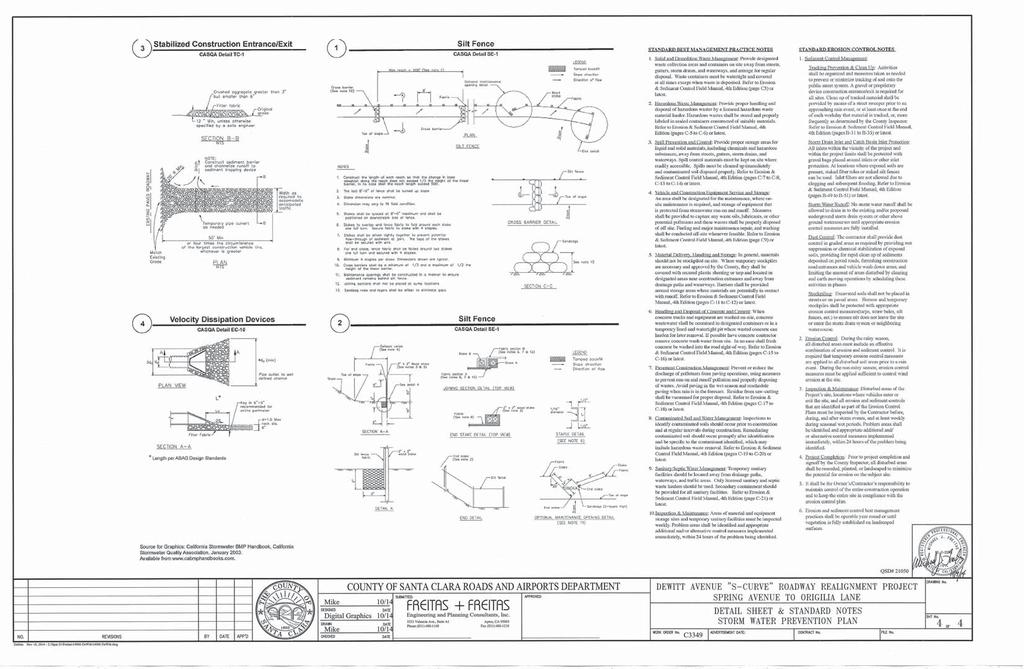
79
80 Appendix C: Permit Registration Documents Permit Registration Documents included in this Appendix Y Y Y Y N Y N Y Permit Registration Document Notice of Intent Risk Assessment Certification Post Water Balance Copy of Annual Fee Receipt ATS Design Documents SWPPP Drawings, see Appendix B SWPPP Dewitt Avenue S-Curve Roadway Realignment Project Morgan Hill, California 70
81 Appendix D: SWPPP Amendment Certifications SWPPP Amendment No. Project Name: Project Number: Qualified SWPPP Developer s Certification of the Stormwater Pollution Prevention Plan Amendment This Stormwater Pollution Prevention Plan and attachments were prepared under my direction to meet the requirements of the California General Permit (SWRCB Order No DWQ as amended by DWQ). I certify that I am a Qualified SWPPP Developer in good standing as of the date signed below. QSD s Signature Date QSD Name QSD Certificate Number Title and Affiliation Telephone Address SWPPP Dewitt Avenue S-Curve Roadway Realignment Project Morgan Hill, California 71
82 Appendix E: Submitted Changes to PRDs Log of Updated PRDs The General Permit allows for the reduction or increase of the total acreage covered under the General Permit when a portion of the project is complete and/or conditions for termination of coverage have been met; when ownership of a portion of the project is purchased by a different entity; or when new acreage is added to the project. Modified PRDs shall be filed electronically within 30 days of a reduction or increase in total disturbed area if a change in permit covered acreage is to be sought. The SWPPP shall be modified appropriately, with revisions and amendments recorded in Appendix C. Updated PRDs submitted electronically via SMARTS can be found in this Appendix. This appendix includes all of the following updated PRDs (check all that apply): Revised Notice of Intent (NOI); Revised SWPPP Drawings; Revised Risk Assessment; New landowner s information (name, address, phone number, address); and New signed certification statement. Legally Responsible Person [if organization] SWPPP Dewitt Avenue S-Curve Roadway Realignment Project Morgan Hill, California 72
83 Signature of [Authorized Representative of] Legally Responsible Person or Approved Signatory Date Name of [Authorized Representative of] Legally Responsible Person or Approved Signatory Telephone Number SWPPP Dewitt Avenue S-Curve Roadway Realignment Project Morgan Hill, California 73
84 Appendix F: Schedule The Contractor shall insert construction schedule here. SWPPP Dewitt Avenue S-Curve Roadway Realignment Project Morgan Hill, California 74
85 Appendix G: Activities, Materials Used, and Associated Pollutants Table G.1 Phase Activities and Associated Pollutants Activity Associated Materials or Pollutants Pollutant Category clearing, grading, grubbing, or excavation sediment Sediment, Nutrients, Bacteria and Viruses, Gross Pollutants, and Vector Production Vehicle and equipment use Oil and Grease Sediment, Nutrients, Bacteria and Viruses, Oil and Grease, Metals, Synthetic Organics, Pesticides, Gross Pollutants, and Vector Production) Grading and Land Development Streets and Utilities Phase Landscaping and Site Stabilization Phase Liquid waste Solid waste Planting / Vegetation Management Wash waters Irrigation line testing/flushing Vegetation control (pesticides/herbicides) Planting Plant maintenance Vegetation removal Gross Pollutants Metals, Synthetic Organics Nutrients, Metals, Synthetic Organics Pools/fountains Chlorinated water Synthetic Organics Sanitary waste Soil preparation/amendments Portable toilets Disturbance of existing sewer lines. Use of soil additives/amendments Nutrients Nutrients SWPPP Dewitt Avenue S-Curve Roadway Realignment Project Morgan Hill, California 75
86 Table G.1 Phase Activities and Associated Pollutants Activity Associated Materials or Pollutants Pollutant Category Solid waste Utility line testing and flushing Vehicle and equipment use Litter, trash and debris Vegetation Hydrostatic test water Pipe flushing Equipment operation Equipment maintenance Equipment washing Equipment fueling Gross Pollutants Synthetic Organics Oil and Grease SWPPP Dewitt Avenue S-Curve Roadway Realignment Project Morgan Hill, California 76
87 Appendix H: CASQA Stormwater BMP Handbook Portal: Fact Sheets The following BMP Fact Sheets are included with this SWPPP: EC-1 Scheduling EC-2 Preservation of Existing Vegetation EC-3 Hydraulic Mulch EC-4 Hydroseed EC-6 Straw Mulch EC-7 Geotextiles and Mats WE-1 Wind Erosion Control SE-1 Silt Fence SE-4 Check Dams SE-5 Fiber Rolls SE-6 Gravel Bag Berm SE-9 Straw Bale Barrier TC-1 Stabilized Entrance and Exit TC-2 Stabilized Roadway TC-3 Entrance Outlet Tire Wash NS-1 Water Conservation Practices NS-2 Dewatering Operation NS-4 Temporary Stream Crossing NS-5 Clear Water Diversion NS-6 Illicit Connection- Illegal Discharge Connection NS-7 Potable Water Irrigation Discharge Detection NS-8 Vehicle and Equipment Cleaning NS-9 Vehicle and Equipment Fueling NS-10 Vehicle and Equipment Maintenance NS-12 Concrete Curing NS-14 Material and Equipment Use Over Water NS-15 Demolition Removal Adjacent to Water WM-01 Material Delivery and Storage WM-02 Material Use WM-03 Stockpile Management WM-04 Spill Prevention and Control WM-05 Solid Waste Management SWPPP Dewitt Avenue S-Curve Roadway Realignment Project Morgan Hill, California 77
88 WM-06 Hazardous Waste Management WM-07 Contaminated Soil Management WM-08 Concrete Waste Management WM-09 Sanitary-Septic Waste Management WM-10 Liquid Waste Management SWPPP Dewitt Avenue S-Curve Roadway Realignment Project Morgan Hill, California 78
89 Scheduling EC-1 Categories EC Erosion Control SE Sediment Control TC Tracking Control WE Wind Erosion Control Non-Stormwater NS Management Control Waste Management and WM Materials Pollution Control Legend: Primary Objective Secondary Objective Description and Purpose Scheduling is the development of a written plan that includes sequencing of construction activities and the implementation of BMPs such as erosion control and sediment control while taking local climate (rainfall, wind, etc.) into consideration. The purpose is to reduce the amount and duration of soil exposed to erosion by wind, rain, runoff, and vehicle tracking, and to perform the construction activities and control practices in accordance with the planned schedule. Suitable Applications Proper sequencing of construction activities to reduce erosion potential should be incorporated into the schedule of every construction project especially during rainy season. Use of other, more costly yet less effective, erosion and sediment control BMPs may often be reduced through proper construction sequencing. Targeted Constituents Sediment Nutrients Trash Metals Bacteria Oil and Grease Organics Potential Alternatives None Limitations Environmental constraints such as nesting season prohibitions reduce the full capabilities of this BMP. Implementation Avoid rainy periods. Schedule major grading operations during dry months when practical. Allow enough time before rainfall begins to stabilize the soil with vegetation or physical means or to install sediment trapping devices. Plan the project and develop a schedule showing each phase November 2009 California Stormwater BMP Handbook 1 of 3
90 Scheduling EC-1 of construction. Clearly show how the rainy season relates to soil disturbing and restabilization activities. Incorporate the construction schedule into the SWPPP. Include on the schedule, details on the rainy season implementation and deployment of: - Erosion control BMPs - Sediment control BMPs - Tracking control BMPs - Wind erosion control BMPs - Non-stormwater BMPs - Waste management and materials pollution control BMPs Include dates for activities that may require non-stormwater discharges such as dewatering, sawcutting, grinding, drilling, boring, crushing, blasting, painting, hydro-demolition, mortar mixing, pavement cleaning, etc. Work out the sequencing and timetable for the start and completion of each item such as site clearing and grubbing, grading, excavation, paving, foundation pouring utilities installation, etc., to minimize the active construction area during the rainy season. - Sequence trenching activities so that most open portions are closed before new trenching begins. - Incorporate staged seeding and re-vegetation of graded slopes as work progresses. - Schedule establishment of permanent vegetation during appropriate planting time for specified vegetation. Non-active areas should be stabilized as soon as practical after the cessation of soil disturbing activities or one day prior to the onset of precipitation. Monitor the weather forecast for rainfall. When rainfall is predicted, adjust the construction schedule to allow the implementation of soil stabilization and sediment treatment controls on all disturbed areas prior to the onset of rain. Be prepared year round to deploy erosion control and sediment control BMPs. Erosion may be caused during dry seasons by un-seasonal rainfall, wind, and vehicle tracking. Keep the site stabilized year round, and retain and maintain rainy season sediment trapping devices in operational condition. Apply permanent erosion control to areas deemed substantially complete during the project s defined seeding window. Costs scheduling to reduce erosion may increase other construction costs due to reduced economies of scale in performing site grading. The cost effectiveness of scheduling techniques should be compared with the other less effective erosion and sedimentation controls to achieve a cost effective balance. November 2009 California Stormwater BMP Handbook 2 of 3
91 Scheduling EC-1 Inspection and Maintenance Verify that work is progressing in accordance with the schedule. If progress deviates, take corrective actions. Amend the schedule when changes are warranted. Amend the schedule prior to the rainy season to show updated information on the deployment and implementation of construction site BMPs. References Stormwater Quality Handbooks Site Best Management Practices (BMPs) Manual, State of California Department of Transportation (Caltrans), November Stormwater Management for Activities Developing Pollution Prevention Plans and Best Management Practices (EPA 832-R ), U.S. Environmental Protection Agency, Office of Water, September November 2009 California Stormwater BMP Handbook 3 of 3
92 Preservation Of Existing Vegetation EC-2 Categories EC Erosion Control SE Sediment Control TC Tracking Control WE Wind Erosion Control Non-Stormwater NS Management Control Waste Management and WM Materials Pollution Control Legend: Primary Objective Secondary Objective Description and Purpose Carefully planned preservation of existing vegetation minimizes the potential of removing or injuring existing trees, vines, shrubs, and grasses that protect soil from erosion. Suitable Applications Preservation of existing vegetation is suitable for use on most projects. Large project sites often provide the greatest opportunity for use of this BMP. Suitable applications include the following: Areas within the site where no construction activity occurs, or occurs at a later date. This BMP is especially suitable to multi year projects where grading can be phased. Targeted Constituents Sediment Nutrients Trash Metals Bacteria Oil and Grease Organics Potential Alternatives None Areas where natural vegetation exists and is designated for preservation. Such areas often include steep slopes, watercourse, and building sites in wooded areas. Areas where local, state, and federal government require preservation, such as vernal pools, wetlands, marshes, certain oak trees, etc. These areas are usually designated on the plans, or in the specifications, permits, or environmental documents. Where vegetation designated for ultimate removal can be temporarily preserved and be utilized for erosion control and sediment control. Limitations Requires forward planning by the owner/developer, November 2009 California Stormwater BMP Handbook 1 of 4
93 Preservation Of Existing Vegetation EC-2 contractor, and design staff. Limited opportunities for use when project plans do not incorporate existing vegetation into the site design. For sites with diverse topography, it is often difficult and expensive to save existing trees while grading the site satisfactory for the planned development. Implementation The best way to prevent erosion is to not disturb the land. In order to reduce the impacts of new development and redevelopment, projects may be designed to avoid disturbing land in sensitive areas of the site (e.g., natural watercourses, steep slopes), and to incorporate unique or desirable existing vegetation into the site s landscaping plan. Clearly marking and leaving a buffer area around these unique areas during construction will help to preserve these areas as well as take advantage of natural erosion prevention and sediment trapping. Existing vegetation to be preserved on the site must be protected from mechanical and other injury while the land is being developed. The purpose of protecting existing vegetation is to ensure the survival of desirable vegetation for shade, beautification, and erosion control. Mature vegetation has extensive root systems that help to hold soil in place, thus reducing erosion. In addition, vegetation helps keep soil from drying rapidly and becoming susceptible to erosion. To effectively save existing vegetation, no disturbances of any kind should be allowed within a defined area around the vegetation. For trees, no construction activity should occur within the drip line of the tree. Timing Provide for preservation of existing vegetation prior to the commencement of clearing and grubbing operations or other soil disturbing activities in areas where no construction activity is planned or will occur at a later date. Design and Layout Mark areas to be preserved with temporary fencing. Include sufficient setback to protect roots. Orange colored plastic mesh fencing works well. Use appropriate fence posts and adequate post spacing and depth to completely support the fence in an upright position. Locate temporary roadways, stockpiles, and layout areas to avoid stands of trees, shrubs, and grass. Consider the impact of grade changes to existing vegetation and the root zone. Maintain existing irrigation systems where feasible. Temporary irrigation may be required. Instruct employees and subcontractors to honor protective devices. Prohibit heavy equipment, vehicular traffic, or storage of construction materials within the protected area. November 2009 California Stormwater BMP Handbook 2 of 4
94 Preservation Of Existing Vegetation EC-2 Costs There is little cost associated with preserving existing vegetation if properly planned during the project design, and these costs may be offset by aesthetic benefits that enhance property values. During construction, the cost for preserving existing vegetation will likely be less than the cost of applying erosion and sediment controls to the disturbed area. Replacing vegetation inadvertently destroyed during construction can be extremely expensive, sometimes in excess of $10,000 per tree. Inspection and Maintenance During construction, the limits of disturbance should remain clearly marked at all times. Irrigation or maintenance of existing vegetation should be described in the landscaping plan. If damage to protected trees still occurs, maintenance guidelines described below should be followed: Verify that protective measures remain in place. Restore damaged protection measures immediately. Serious tree injuries shall be attended to by an arborist. Damage to the crown, trunk, or root system of a retained tree shall be repaired immediately. Trench as far from tree trunks as possible, usually outside of the tree drip line or canopy. Curve trenches around trees to avoid large roots or root concentrations. If roots are encountered, consider tunneling under them. When trenching or tunneling near or under trees to be retained, place tunnels at least 18 in. below the ground surface, and not below the tree center to minimize impact on the roots. Do not leave tree roots exposed to air. Cover exposed roots with soil as soon as possible. If soil covering is not practical, protect exposed roots with wet burlap or peat moss until the tunnel or trench is ready for backfill. Cleanly remove the ends of damaged roots with a smooth cut. Fill trenches and tunnels as soon as possible. Careful filling and tamping will eliminate air spaces in the soil, which can damage roots. If bark damage occurs, cut back all loosened bark into the undamaged area, with the cut tapered at the top and bottom and drainage provided at the base of the wood. Limit cutting the undamaged area as much as possible. Aerate soil that has been compacted over a trees root zone by punching holes 12 in. deep with an iron bar, and moving the bar back and forth until the soil is loosened. Place holes 18 in. apart throughout the area of compacted soil under the tree crown. Fertilization Fertilize stressed or damaged broadleaf trees to aid recovery. Fertilize trees in the late fall or early spring. November 2009 California Stormwater BMP Handbook 3 of 4
95 Preservation Of Existing Vegetation EC-2 - Apply fertilizer to the soil over the feeder roots and in accordance with label instructions, but never closer than 3 ft to the trunk. Increase the fertilized area by one-fourth of the crown area for conifers that have extended root systems. Retain protective measures until all other construction activity is complete to avoid damage during site cleanup and stabilization. References County of Sacramento Tree Preservation Ordinance, September Stormwater Quality Handbooks Site Best Management Practices (BMPs) Manual, State of California Department of Transportation (Caltrans), November Stormwater Management of the Puget Sound Basin, Technical Manual, Publication #91-75, Washington State Department of Ecology, February Water Quality Management Plan for The Lake Tahoe Region, Volume II, Handbook of Management Practices, Tahoe Regional Planning Agency, November November 2009 California Stormwater BMP Handbook 4 of 4
96 Hydraulic Mulch EC-3 Categories EC Erosion Control SE Sediment Control TC Tracking Control WE Wind Erosion Control Non-Stormwater NS Management Control Waste Management and WM Materials Pollution Control Legend: Primary Category Secondary Category Description and Purpose Hydraulic Mulch consists of various types of fibrous materials mixed with water and sprayed onto the soil surface in slurry form to provide a layer of temporary protection from wind and water erosion. Suitable Applications Hydraulic mulch as a temporary, stand alone, erosion control BMP is suitable for disturbed areas that require temporary protection from wind and water erosion until permanent soil stabilization activities commence. Examples include: Rough-graded areas that will remain inactive for longer than permit-required thresholds (e.g., 14 days) or otherwise require stabilization to minimize erosion or prevent sediment discharges. Soil stockpiles. Slopes with exposed soil between existing vegetation such as trees or shrubs. Targeted Constituents Sediment Nutrients Trash Metals Bacteria Oil and Grease Organics Potential Alternatives EC-4 Hydroseeding EC-5 Soil Binders EC-6 Straw Mulch EC-7 Geotextiles and Mats EC-8 Wood Mulching EC-14 Compost Blanket EC-16 Non-Vegetative Stabilization Slopes planted with live, container-grown vegetation or plugs. Slopes burned by wildfire. Hydraulic mulch can also be applied to augment other erosion control BMPs such as: November 2009 California Stormwater BMP Handbook 1 of 5
97 Hydraulic Mulch EC-3 In conjunction with straw mulch (see EC-6 Straw Mulch) where the rate of hydraulic mulch is reduced to lbs per acre and the slurry is applied over the straw as a tackifying agent to hold the straw in place. Supplemental application of soil amendments, such as fertilizer, lime, gypsum, soil biostimulants or compost. Limitations In general, hydraulic mulch is not limited by slope length, gradient or soil type. However, the following limitations typically apply: Most hydraulic mulch applications, particularly bonded fiber matrices (BFMs), require at least 24 hours to dry before rainfall occurs. Temporary applications (i.e., without a vegetative component) may require a second application in order to remain effective for an entire rainy season. Treatment areas must be accessible to hydraulic mulching equipment. Availability of water sources in remote areas for mixing and application. As a stand-alone temporary BMP, hydraulic mulches may need to be re-applied to maintain their erosion control effectiveness, typically after 6-12 months depending on the type of mulch used. Availability of hydraulic mulching equipment may be limited just prior to the rainy season and prior to storms due to high demand. Cellulose fiber mulches alone may not perform well on steep slopes or in course soils. Implementation Where feasible, it is preferable to prepare soil surfaces prior to application by roughening embankments and fill areas with a crimping or punching type roller or by track walking. The majority of hydraulic mulch applications do not necessarily require surface/soil preparation (See EC-15 Soil Preparation) although in almost every case where re-vegetation is included as part of the practice, soil preparation can be beneficial. One of the advantages of hydraulic mulch over other erosion control methods is that it can be applied in areas where soil preparation is precluded by site conditions, such as steep slopes, rocky soils, or inaccessibility. Avoid mulch over spray onto roads, sidewalks, drainage channels, existing vegetation, etc. Hydraulic mulching is generally performed utilizing specialized machines that have a large water-holding/mixing tank and some form of mechanical agitation or other recirculation method to keep water, mulch and soil amendments in suspension. The mixed hydraulic slurry can be applied from a tower sprayer on top of the machine or by extending a hose to areas remote from the machine. November 2009 California Stormwater BMP Handbook 2 of 5
98 Hydraulic Mulch EC-3 Where possible apply hydraulic mulch from multiple directions to adequately cover the soil. Application from a single direction can result in shadowing, uneven coverage and failure of the BMP. Hydraulic mulch can also include a vegetative component, such as seed, rhizomes, or stolons (see EC-4 Hydraulic Seed). Typical hydraulic mulch application rates range from 2,000 pounds per acre for standard mulches (SMs) to 3,500 pounds per acre for BFMs. However, the required amount of hydraulic mulch to provide adequate coverage of exposed topsoil may appear to exceed the standard rates when the roughness of the soil surface is changed due to soil preparation methods (see EC-15 Soil Preparation) or by slope gradient. Other factors such as existing soil moisture and soil texture can have a profound effect on the amount of hydraulic mulch required (i.e. application rate) applied to achieve an erosionresistant covering. Avoid use of mulch without a tackifier component, especially on slopes. Mulches used in the hydraulic mulch slurry can include: - Cellulose fiber - Thermally-processed wood fibers - Cotton - Synthetics - Compost (see EC-14, Compost Blanket) Additional guidance on the comparison and selection of temporary slope stabilization methods is provided in Appendix F of the Handbook. Categories of Hydraulic Mulches Standard Hydraulic Mulch (SM) Standard hydraulic mulches are generally applied at a rate of 2,000 pounds per acre and are manufactured containing around 5% tackifier (i.e. soil binder), usually a plant-derived guar or psyllium type. Most standard mulches are green in color derived from food-color based dyes. Hydraulic Matrices (HM) and Stabilized Fiber Matrices (SFM) Hydraulic matrices and stabilized fiber matrices are slurries which contain increased levels of tackifiers/soil binders; usually 10% or more by weight. HMs and SFMs have improved performance compared to a standard hydraulic mulch (SM) because of the additional percentage of tackifier and because of their higher application rates, typically 2,500 4,000 pounds per acre. Hydraulic matrices can include a mixture of fibers, for example, a 50/50 blend of paper and wood fiber. In the case of an SFM, the tackifier/soil binder is specified as a polyacrylamide (PAM). November 2009 California Stormwater BMP Handbook 3 of 5
99 Hydraulic Mulch EC-3 Bonded Fiber Matrix (BFM) Bonded fiber matrices (BFMs) are hydraulically-applied systems of fibers, adhesives (typically guar based) and chemical cross-links. Upon drying, the slurry forms an erosion-resistant blanket that prevents soil erosion and promotes vegetation establishment. The cross-linked adhesive in the BFM should be biodegradable and should not dissolve or disperse upon rewetting. BFMs are typically applied at rates from 3,000 to 4,000 lbs/acre based on the manufacturer s recommendation. BFMs should not be applied immediately before, during or immediately after rainfall or if the soil is saturated. Depending on the product, BFMs typically require 12 to 24 hours to dry and become effective. Mechanically-Bonded Fiber Matrices (MBFM) Mechanically-bonded fiber matrices (MBFMs) are hydraulically applied systems similar to BFM that use crimped synthetic fibers and PAM and are typically applied to a slope at a higher application rate than a standard BFM. Hydraulic Compost Matrix (HCM) Hydraulic compost matrix (HCM) is a field-derived practice whereby finely graded or sifted compost is introduced into the hydraulic mulch slurry. A guar-type tackifier can be added for steeper slope applications as well as any specified seed mixtures. A HCM can help to accelerate seed germination and growth. HCMs are particularly useful as an in-fill for three-dimensional re-vegetation geocomposites, such as turf reinforcement mats (TRM) (see EC-7 Geotextiles and Mats). Costs Average installed costs for hydraulic mulch categories are is provided in Table 1, below. Table 1 HYDRAULIC MULCH BMPs INSTALLED COSTS BMP Installed Cost/Acre Standard Hydraulic Mulching (SM) $1,700 - $3,600 per acre Hydraulic Matrices (HM) and Stabilized Fiber Matrices Guar-based PAM-based $2,000 - $4,000 per acre $2,500 - $5,610 per acre Bonded Fiber Matrix (BFM) $3,900 - $6,900 per acre Mechanically Bonded Fiber Matrix (MBFM) $4,500 - $6,000 per acre Hydraulic Compost Matrix (HCM) $3,000 - $3,500 per acre Source: Caltrans Soil Stabilization BMP Research for Erosion and Sediment Controls, July 2007 Inspection and Maintenance Maintain an unbroken, temporary mulched ground cover throughout the period of construction when the soils are not being reworked. BMPs must be inspected in accordance with General Permit requirements for the associated project type and risk level. It is recommended that at a minimum, BMPs be inspected November 2009 California Stormwater BMP Handbook 4 of 5
100 Hydraulic Mulch EC-3 weekly, prior to forecasted rain events, daily during extended rain events, and after the conclusion of rain events. Areas where erosion is evident should be repaired and BMPs re-applied as soon as possible. Care should be exercised to minimize the damage to protected areas while making repairs, as any area damaged will require re-application of BMPs. Compare the number of bags or weight of applied mulch to the area treated to determine actual application rates and compliance with specifications. References Soil Stabilization BMP Research for Erosion and Sediment Controls: Cost Survey Technical Memorandum, State of California Department of Transportation (Caltrans), July Controlling Erosion of Sites, Agricultural Information #347, U.S. Department of Agriculture (USDA), Natural Resources Conservation Service (NRCS) (formerly Soil Conservation Service SCS). Guides for Erosion and Sediment Control in California, USDA Soils Conservation Service, January Manual of Standards of Erosion and Sediment Control Measures, Association of Bay Area Governments, May Sedimentation and Erosion Control, An Inventory of Current Practices Draft, US EPA, April Soil Erosion by Water, Agriculture Information Bulletin #513, U.S. Department of Agriculture, Soil Conservation Service. Stormwater Quality Handbooks Site Best Management Practices (BMPs) Manual, State of California Department of Transportation (Caltrans), March Guidance Document: Soil Stabilization for Temporary Slopes, State of California Department of Transportation (Caltrans), November 1999 Stormwater Management of the Puget Sound Basin, Technical Manual, Publication #91-75, Washington State Department of Ecology, February Water Quality Management Plan for the Lake Tahoe Region, Volume II, Handbook of Management Practices, Tahoe Regional Planning Agency, November November 2009 California Stormwater BMP Handbook 5 of 5
101 Hydroseeding EC-4 Categories EC Erosion Control SE Sediment Control TC Tracking Control WE Wind Erosion Control Non-Stormwater NS Management Control Waste Management and WM Materials Pollution Control Legend: Primary Category Secondary Category Description and Purpose Hydroseeding typically consists of applying a mixture of a hydraulic mulch, seed, fertilizer, and stabilizing emulsion with a hydraulic mulcher, to temporarily protect exposed soils from erosion by water and wind. Hydraulic seeding, or hydroseeding, is simply the method by which temporary or permanent seed is applied to the soil surface. Suitable Applications Hydroseeding is suitable for disturbed areas requiring temporary protection until permanent stabilization is established, for disturbed areas that will be re-disturbed following an extended period of inactivity, or to apply permanent stabilization measures. Hydroseeding without mulch or other cover (e.g. EC-7, Erosion Control Blanket) is not a stand-alone erosion control BMP and should be combined with additional measures until vegetation establishment. Typical applications for hydroseeding include: Disturbed soil/graded areas where permanent stabilization or continued earthwork is not anticipated prior to seed germination. Targeted Constituents Sediment Nutrients Trash Metals Bacteria Oil and Grease Organics Potential Alternatives EC-3 Hydraulic Mulch EC-5 Soil Binders EC-6 Straw Mulch EC-7 Geotextiles and Mats EC-8 Wood Mulching EC-14 Compost Blanket EC-16 Non-Vegetative Stabilization Cleared and graded areas exposed to seasonal rains or temporary irrigation. Areas not subject to heavy wear by construction equipment or high traffic. November 2009 California Stormwater BMP Handbook 1 of 4
102 Hydroseeding EC-4 Limitations Availability of hydroseeding equipment may be limited just prior to the rainy season and prior to storms due to high demand. Hydraulic seed should be applied with hydraulic mulch or a stand-alone hydroseed application should be followed by one of the following: - Straw mulch (see Straw Mulch EC-6) - Rolled erosion control products (see Geotextiles and Mats EC-7) - Application of Compost Blanket (see Compost Blanket EC-14) Hydraulic seed may be used alone only on small flat surfaces when there is sufficient time in the season to ensure adequate vegetation establishment and coverage to provide adequate erosion control. Hydraulic seed without mulch does not provide immediate erosion control. Temporary seeding may not be appropriate for steep slopes (i.e., slopes readily prone to rill erosion or without sufficient topsoil). Temporary seeding may not be appropriate in dry periods without supplemental irrigation. Temporary vegetation may have to be removed before permanent vegetation is applied. Temporary vegetation may not be appropriate for short term inactivity (i.e. less than 3-6 months). Implementation In order to select appropriate hydraulic seed mixtures, an evaluation of site conditions should be performed with respect to: - Soil conditions - Maintenance requirements - Site topography and exposure (sun/wind) - Sensitive adjacent areas - Season and climate - Water availability - Vegetation types - Plans for permanent vegetation The local office of the U.S.D.A. Natural Resources Conservation Service (NRCS) is an excellent source of information on appropriate seed mixes. The following steps should be followed for implementation: Where appropriate or feasible, soil should be prepared to receive the seed by disking or otherwise scarifying (See EC-15, Soil Preparation) the surface to eliminate crust, improve air and water infiltration and create a more favorable environment for germination and growth. November 2009 California Stormwater BMP Handbook 2 of 4
103 Hydroseeding EC-4 Avoid use of hydraulic seed in areas where the BMP would be incompatible with future earthwork activities. Hydraulic seed can be applied using a multiple step or one step process. - In a multiple step process, hydraulic seed is applied first, followed by mulch or a Rolled Erosion Control Product (RECP). - In the one step process, hydraulic seed is applied with hydraulic mulch in a hydraulic matrix. When the one step process is used to apply the mixture of fiber, seed, etc., the seed rate should be increased to compensate for all seeds not having direct contact with the soil. All hydraulically seeded areas should have mulch, or alternate erosion control cover to keep seeds in place and to moderate soil moisture and temperature until the seeds germinate and grow. All seeds should be in conformance with the California State Seed Law of the Department of Agriculture. Each seed bag should be delivered to the site sealed and clearly marked as to species, purity, percent germination, dealer's guarantee, and dates of test. The container should be labeled to clearly reflect the amount of Pure Live Seed (PLS) contained. All legume seed should be pellet inoculated. Inoculant sources should be species specific and should be applied at a rate of 2 lb of inoculant per 100 lb seed. Commercial fertilizer should conform to the requirements of the California Food and Agricultural Code, which can be found at Fertilizer should be pelleted or granular form. Follow up applications should be made as needed to cover areas of poor coverage or germination/vegetation establishment and to maintain adequate soil protection. Avoid over spray onto roads, sidewalks, drainage channels, existing vegetation, etc. Additional guidance on the comparison and selection of temporary slope stabilization methods is provided in Appendix F of the Handbook. Costs Average cost for installation and maintenance may vary from as low as $1,900 per acre for flat slopes and stable soils, to $4,000 per acre for moderate to steep slopes and/or erosive soils. Cost of seed mixtures vary based on types of required vegetation. BMP Installed Cost per Acre Hydraulic Seed $1,900-$4,000 Source: Caltrans Soil Stabilization BMP Research for Erosion and Sediment Controls, July 2007 November 2009 California Stormwater BMP Handbook 3 of 4
104 Hydroseeding EC-4 Inspection and Maintenance BMPs must be inspected in accordance with General Permit requirements for the associated project type and risk level. It is recommended that at a minimum, BMPs be inspected weekly, prior to forecasted rain events, daily during extended rain events, and after the conclusion of rain events. Areas where erosion is evident should be repaired and BMPs re-applied as soon as possible. Care should be exercised to minimize the damage to protected areas while making repairs, as any area damaged will require re-application of BMPs. Where seeds fail to germinate, or they germinate and die, the area must be re-seeded, fertilized, and mulched within the planting season, using not less than half the original application rates. Irrigation systems, if applicable, should be inspected daily while in use to identify system malfunctions and line breaks. When line breaks are detected, the system must be shut down immediately and breaks repaired before the system is put back into operation. Irrigation systems should be inspected for complete coverage and adjusted as needed to maintain complete coverage. References Soil Stabilization BMP Research for Erosion and Sediment Controls: Cost Survey Technical Memorandum, State of California Department of Transportation (Caltrans), July Stormwater Quality Handbooks Site Best Management Practices (BMPs) Manual, State of California Department of Transportation (Caltrans), March Guidance Document: Soil Stabilization for Temporary Slopes, State of California Department of Transportation (Caltrans), November November 2009 California Stormwater BMP Handbook 4 of 4
105 Straw Mulch EC-6 Categories EC Erosion Control SE Sediment Control TC Tracking Control WE Wind Erosion Control Non-Stormwater NS Management Control Waste Management and WM Materials Pollution Control Legend: Primary Category Secondary Category Description and Purpose Straw mulch consists of placing a uniform layer of straw and incorporating it into the soil with a studded roller or crimper, or anchoring it with a tackifier or stabilizing emulsion. Straw mulch protects the soil surface from the impact of rain drops, preventing soil particles from becoming dislodged. Suitable Applications Straw mulch is suitable for disturbed areas requiring temporary protection until permanent stabilization is established. Straw mulch can be specified for the following applications: As a stand-alone BMP on disturbed areas until soils can be prepared for permanent vegetation. The longevity of straw mulch is typically less than six months. Applied in combination with temporary seeding strategies Applied in combination with permanent seeding strategies to enhance plant establishment and final soil stabilization Targeted Constituents Sediment Nutrients Trash Metals Bacteria Oil and Grease Organics Potential Alternatives EC-3 Hydraulic Mulch EC-4 Hydroseeding EC-5 Soil Binders EC-7 Geotextiles and Mats EC-8 Wood Mulching EC-14 Compost Blanket Applied around containerized plantings to control erosion until the plants become established to provide permanent stabilization Limitations Availability of straw and straw blowing equipment may be limited just prior to the rainy season and prior to storms due to high demand. November 2009 California Stormwater BMP Handbook 1 of 4
106 Straw Mulch EC-6 There is a potential for introduction of weed seed and unwanted plant material if weed-free agricultural straw is not specified. Straw mulch applied by hand is more time intensive and potentially costly. Wind may limit application of straw and blow straw into undesired locations. May have to be removed prior to permanent seeding or prior to further earthwork. Punching of straw does not work in sandy soils, necessitating the use of tackifiers. Potential fugitive dust control issues associated with straw applications can occur. Application of a stabilizing emulsion or a water stream at the same time straw is being blown can reduce this problem. Use of plastic netting should be avoided in areas where wildlife may be entrapped and may be prohibited for projects in certain areas with sensitive wildlife species, especially reptiles and amphibians. Implementation Straw should be derived from weed-free wheat, rice, or barley. Where required by the plans, specifications, permits, or environmental documents, native grass straw should be used. Use tackifier to anchor straw mulch to the soil on slopes. Crimping, punch roller-type rollers, or track walking may also be used to incorporate straw mulch into the soil on slopes. Track walking can be used where other methods are impractical. Avoid placing straw onto roads, sidewalks, drainage channels, sound walls, existing vegetation, etc. Straw mulch with tackifier should not be applied during or immediately before rainfall. Additional guidance on the comparison and selection of temporary slope stabilization methods is provided in Appendix F of the Handbook. Application Procedures When using a tackifier to anchor the straw mulch, roughen embankment or fill areas by rolling with a crimping or punching-type roller or by track walking before placing the straw mulch. Track walking should only be used where rolling is impractical. Apply straw at a rate of between 3,000 and 4,000 lb/acre, either by machine or by hand distribution and provide 100% ground cover. A lighter application is used for flat surfaces and a heavier application is used for slopes. Evenly distribute straw mulch on the soil surface. Anchoring straw mulch to the soil surface by "punching" it into the soil mechanically (incorporating) can be used in lieu of a tackifier. November 2009 California Stormwater BMP Handbook 2 of 4
107 Straw Mulch EC-6 Methods for holding the straw mulch in place depend upon the slope steepness, accessibility, soil conditions, and longevity. - A tackifier acts to glue the straw fibers together and to the soil surface. The tackifier should be selected based on longevity and ability to hold the fibers in place. A tackifier is typically applied at a rate of 125 lb/acre. In windy conditions, the rates are typically 180 lb/acre. - On very small areas, a spade or shovel can be used to punch in straw mulch. - On slopes with soils that are stable enough and of sufficient gradient to safely support construction equipment without contributing to compaction and instability problems, straw can be "punched" into the ground using a knife blade roller or a straight bladed coulter, known commercially as a "crimper. Costs Average annual cost for installation and maintenance is included in the table below. Application by hand is more time intensive and potentially more costly. BMP Unit Cost per Acre Straw mulch, crimped or punched $2,458-$5,375 Straw mulch with tackifier $1,823-$4,802 Source: Caltrans Soil Stabilization BMP Research for Erosion and Sediment Controls, July 2007 Inspection and Maintenance BMPs must be inspected in accordance with General Permit requirements for the associated project type and risk level. It is recommended that at a minimum, BMPs be inspected weekly, prior to forecasted rain events, daily during extended rain events, and after the conclusion of rain events. Areas where erosion is evident should be repaired and BMPs re-applied as soon as possible. Care should be exercised to minimize the damage to protected areas while making repairs, as any area damaged will require re-application of BMPs. The key consideration in inspection and maintenance is that the straw needs to last long enough to achieve erosion control objectives. Straw mulch as a stand-alone BMP is temporary and is not suited for long-term erosion control. Maintain an unbroken, temporary mulched ground cover while disturbed soil areas are inactive. Repair any damaged ground cover and re-mulch exposed areas. Reapplication of straw mulch and tackifier may be required to maintain effective soil stabilization over disturbed areas and slopes. November 2009 California Stormwater BMP Handbook 3 of 4
108 Straw Mulch EC-6 References Soil Stabilization BMP Research for Erosion and Sediment Controls: Cost Survey Technical Memorandum, State of California Department of Transportation (Caltrans), July Erosion and Sediment Control Manual, Oregon Department of Environmental Quality, February Controlling Erosion of Sites, Agricultural Information Bulletin #347, U.S. Department of Agriculture (USDA), Natural Resources Conservation Service (NRCS) (formerly Soil Conservation Service SCS). Guides for Erosion and Sediment Control in California, USDA Soils Conservation Service, January Manual of Standards of Erosion and Sediment Control Measures, Association of Bay Area Governments, May Soil Erosion by Water, Agricultural Information Bulletin #513, U.S. Department of Agriculture, Soil Conservation Service. Stormwater Quality Handbooks Site Best Management Practices (BMPs) Manual, State of California Department of Transportation (Caltrans), March Stormwater Management of the Puget Sound Basin, Technical Manual, Publication #91-75, Washington State Department of Ecology, February Water Quality Management Plan for the Lake Tahoe Region, Volume II, Handbook of Management Practices, Tahoe Regional Planning Agency, November November 2009 California Stormwater BMP Handbook 4 of 4
109 Geotextiles and Mats EC-7 Categories EC Erosion Control SE Sediment Control TC Tracking Control WE Wind Erosion Control Non-Stormwater NS Management Control Waste Management and WM Materials Pollution Control Legend: Primary Category Secondary Category Description and Purpose Mattings, or Rolled Erosion Control Products (RECPs), can be made of natural or synthetic materials or a combination of the two. RECPs are used to cover the soil surface to reduce erosion from rainfall impact, hold soil in place, and absorb and hold moisture near the soil surface. Additionally, RECPs may be used to stabilize soils until vegetation is established or to reinforce non-woody surface vegetation. Suitable Applications RECPs are typically applied on slopes where erosion hazard is high and vegetation will be slow to establish. Mattings are also used on stream banks, swales and other drainage channels where moving water at velocities between 3 ft/s and 6 ft/s are likely to cause scour and wash out new vegetation, and in areas where the soil surface is disturbed and where existing vegetation has been removed. RECPs may also be used when seeding cannot occur (e.g., late season construction and/or the arrival of an early rain season). RECPs should be considered when the soils are fine grained and potentially erosive. RECPs should be considered in the following situations. Targeted Constituents Sediment Nutrients Trash Metals Bacteria Oil and Grease Organics Potential Alternatives EC-3 Hydraulic Mulch EC-4 Hydroseeding Steep slopes, generally steeper than 3:1 (H:V) Slopes where the erosion potential is high Slopes and disturbed soils where mulch must be anchored Disturbed areas where plants are slow to develop November 2009 California Stormwater BMP Handbook 1 of 12
110 Geotextiles and Mats EC-7 Channels with flows exceeding 3.3 ft/s Channels to be vegetated Stockpiles Slopes adjacent to water bodies Limitations RECP installed costs are generally higher than other erosion control BMPs, limiting their use to areas where other BMPs are ineffective (e.g. channels, steep slopes). RECPs may delay seed germination, due to reduction in soil temperature. RECPs are generally not suitable for excessively rocky sites or areas where the final vegetation will be mowed (since staples and netting can catch in mowers). If a staple or pin cannot be driven into the soil because the underlying soil is too hard or rocky, then an alternative BMP should be selected. If used for temporary erosion control, RECPs should be removed and disposed of prior to application of permanent soil stabilization measures. The use of plastic should be limited to covering stockpiles or very small graded areas for short periods of time (such as through one imminent storm event) until more environmentally friendly measures, such as seeding and mulching, may be installed. - Plastic sheeting is easily vandalized, easily torn, photodegradable, and must be disposed of at a landfill. - Plastic sheeting results in 100% runoff, which may cause serious erosion problems in the areas receiving the increased flow. RECPs may have limitations based on soil type, slope gradient, or channel flow rate; consult the manufacturer for proper selection. Not suitable for areas that have foot traffic (tripping hazard) e.g., pad areas around buildings under construction. RECPs that incorporate a plastic netting (e.g. straw blanket typically uses a plastic netting to hold the straw in place) may not be suitable near known wildlife habitat. Wildlife can become trapped in the plastic netting. RECPs may have limitations in extremely windy climates. However, when RECPs are properly trenched at the top and bottom and stapled in accordance with the manufacturer s recommendations, problems with wind can be minimized. November 2009 California Stormwater BMP Handbook 2 of 12
111 Geotextiles and Mats EC-7 Implementation Material Selection Natural RECPs have been found to be effective where re-vegetation will be provided by reseeding. The choice of material should be based on the size of area, side slopes, surface conditions such as hardness, moisture, weed growth, and availability of materials. Additional guidance on the comparison and selection of temporary slope stabilization methods is provided in Appendix F of the Handbook. The following natural and synthetic RECPs are commonly used: Geotextiles Material can be a woven or a non-woven polypropylene fabric with minimum thickness of 0.06 in., minimum width of 12 ft and should have minimum tensile strength of 150 lbs (warp), 80 lbs (fill) in conformance with the requirements in ASTM Designation: D The permittivity of the fabric should be approximately 0.07 sec 1 in conformance with the requirements in ASTM Designation: D4491. The fabric should have an ultraviolet (UV) stability of 70 percent in conformance with the requirements in ASTM designation: D4355. Geotextile blankets must be secured in place with wire staples or sandbags and by keying into tops of slopes to prevent infiltration of surface waters under geotextile. Staples should be made of minimum 11 gauge steel wire and should be U-shaped with 8 in. legs and 2 in. crown. Geotextiles may be reused if they are suitable for the use intended. Plastic Covers Generally plastic sheeting should only be used as stockpile covering or for very small graded areas for short periods of time (such as through one imminent storm event). If plastic sheeting must be used, choose a plastic that will withstand photo degradation. Plastic sheeting should have a minimum thickness of 6 mils, and must be keyed in at the top of slope (when used as a temporary slope protection) and firmly held in place with sandbags or other weights placed no more than 10 ft apart. Seams are typically taped or weighted down their entire length, and there should be at least a 12 in. to 24 in. overlap of all seams. Edges should be embedded a minimum of 6 in. in soil (when used as a temporary slope protection). All sheeting must be inspected periodically after installation and after significant rainstorms to check for erosion, undermining, and anchorage failure. Any failures must be repaired immediately. If washout or breakages occur, the material should be re-installed after repairing the damage to the slope. Erosion Control Blankets/Mats Biodegradable RECPs are typically composed of jute fibers, curled wood fibers, straw, coconut fiber, or a combination of these materials. In order for an RECP to be considered 100% biodegradable, the netting, sewing or adhesive system that holds the biodegradable mulch fibers together must also be biodegradable. See typical installation details at the end of this fact sheet. November 2009 California Stormwater BMP Handbook 3 of 12
112 Geotextiles and Mats EC-7 - Jute is a natural fiber that is made into a yarn that is loosely woven into a biodegradable mesh. The performance of jute as a stand-alone RECP is low. Most other RECPs outperform jute as a temporary erosion control product and therefore jute is not commonly used. It is designed to be used in conjunction with vegetation. The material is supplied in rolled strips, which should be secured to the soil with U-shaped staples or stakes in accordance with manufacturers recommendations. - Excelsior (curled wood fiber) blanket material should consist of machine produced mats of curled wood excelsior with 80 percent of the fiber 6 in. or longer. The excelsior blanket should be of consistent thickness. The wood fiber must be evenly distributed over the entire area of the blanket. The top surface of the blanket should be covered with a photodegradable extruded plastic mesh. The blanket should be smolder resistant without the use of chemical additives and should be non-toxic and non-injurious to plant and animal life. Excelsior blankets should be furnished in rolled strips, a minimum of 48 in. wide, and should have an average weight of 0.8 lb/yd 2, ±10 percent, at the time of manufacture. Excelsior blankets must be secured in place with wire staples. Staples should be made of minimum 11 gauge steel wire and should be U-shaped with 8 in. legs and 2 in. crown. - Straw blanket should be machine produced mats of straw with a lightweight biodegradable netting top layer. The straw should be attached to the netting with biodegradable thread or glue strips. The straw blanket should be of consistent thickness. The straw should be evenly distributed over the entire area of the blanket. Straw blanket should be furnished in rolled strips a minimum of 6.5 ft wide, a minimum of 80 ft long and a minimum of 0.5 lb/yd 2. Straw blankets must be secured in place with wire staples. Staples should be made of minimum 11 gauge steel wire and should be U-shaped with 8 in. legs and 2 in. crown. - Wood fiber blanket is composed of biodegradable fiber mulch with extruded plastic netting held together with adhesives. The material is designed to enhance re-vegetation. The material is furnished in rolled strips, which must be secured to the ground with U- shaped staples or stakes in accordance with manufacturers recommendations. - Coconut fiber blanket should be a machine produced mat of 100 percent coconut fiber with biodegradable netting on the top and bottom. The coconut fiber should be attached to the netting with biodegradable thread or glue strips. The coconut fiber blanket should be of consistent thickness. The coconut fiber should be evenly distributed over the entire area of the blanket. Coconut fiber blanket should be furnished in rolled strips with a minimum of 6.5 ft wide, a minimum of 80 ft. long and a minimum of 0.5 lb/yd 2. Coconut fiber blankets must be secured in place with wire staples. Staples should be made of minimum 11 gauge steel wire and should be U-shaped with 8 in. legs and 2 in. crown. - Coconut fiber mesh is a thin permeable membrane made from coconut or corn fiber that is spun into a yarn and woven into a biodegradable mat. It is designed to be used in conjunction with vegetation and typically has longevity of several years. The material is supplied in rolled strips, which must be secured to the soil with U-shaped staples or stakes in accordance with manufacturers recommendations. November 2009 California Stormwater BMP Handbook 4 of 12
113 Geotextiles and Mats EC-7 - Straw coconut fiber blanket should be machine produced mats of 70 percent straw and 30 percent coconut fiber with a biodegradable netting top layer and a biodegradable bottom net. The straw and coconut fiber should be attached to the netting with biodegradable thread or glue strips. The straw coconut fiber blanket should be of consistent thickness. The straw and coconut fiber should be evenly distributed over the entire area of the blanket. Straw coconut fiber blanket should be furnished in rolled strips a minimum of 6.5 ft wide, a minimum of 80 ft long and a minimum of 0.5 lb/yd 2. Straw coconut fiber blankets must be secured in place with wire staples. Staples should be made of minimum 11 gauge steel wire and should be U-shaped with 8 in. legs and 2 in. crown. Non-biodegradable RECPs are typically composed of polypropylene, polyethylene, nylon or other synthetic fibers. In some cases, a combination of biodegradable and synthetic fibers is used to construct the RECP. Netting used to hold these fibers together is typically nonbiodegradable as well. - Plastic netting is a lightweight biaxially oriented netting designed for securing loose mulches like straw or paper to soil surfaces to establish vegetation. The netting is photodegradable. The netting is supplied in rolled strips, which must be secured with U- shaped staples or stakes in accordance with manufacturers recommendations. - Plastic mesh is an open weave geotextile that is composed of an extruded synthetic fiber woven into a mesh with an opening size of less than ¼ in. It is used with revegetation or may be used to secure loose fiber such as straw to the ground. The material is supplied in rolled strips, which must be secured to the soil with U-shaped staples or stakes in accordance with manufacturers recommendations. - Synthetic fiber with netting is a mat that is composed of durable synthetic fibers treated to resist chemicals and ultraviolet light. The mat is a dense, three dimensional mesh of synthetic (typically polyolefin) fibers stitched between two polypropylene nets. The mats are designed to be re-vegetated and provide a permanent composite system of soil, roots, and geomatrix. The material is furnished in rolled strips, which must be secured with U-shaped staples or stakes in accordance with manufacturers recommendations. - Bonded synthetic fibers consist of a three dimensional geomatrix nylon (or other synthetic) matting. Typically it has more than 90 percent open area, which facilitates root growth. It s tough root reinforcing system anchors vegetation and protects against hydraulic lift and shear forces created by high volume discharges. It can be installed over prepared soil, followed by seeding into the mat. Once vegetated, it becomes an invisible composite system of soil, roots, and geomatrix. The material is furnished in rolled strips that must be secured with U-shaped staples or stakes in accordance with manufacturers recommendations. - Combination synthetic and biodegradable RECPs consist of biodegradable fibers, such as wood fiber or coconut fiber, with a heavy polypropylene net stitched to the top and a high strength continuous filament geomatrix or net stitched to the bottom. The material is designed to enhance re-vegetation. The material is furnished in rolled strips, November 2009 California Stormwater BMP Handbook 5 of 12
114 Geotextiles and Mats EC-7 which must be secured with U-shaped staples or stakes in accordance with manufacturers recommendations. Site Preparation Proper soil preparation is essential to ensure complete contact of the RECP with the soil. Soil Roughening is not recommended in areas where RECPs will be installed. Grade and shape the area of installation. Remove all rocks, clods, vegetation or other obstructions so that the installed blankets or mats will have complete, direct contact with the soil. Prepare seedbed by loosening 2 to 3 in. of topsoil. Seeding/Planting Seed the area before blanket installation for erosion control and re-vegetation. Seeding after mat installation is often specified for turf reinforcement application. When seeding prior to blanket installation, all areas disturbed during blanket installation must be re-seeded. Where soil filling is specified for turf reinforcement mats (TRMs), seed the matting and the entire disturbed area after installation and prior to filling the mat with soil. Fertilize and seed in accordance with seeding specifications or other types of landscaping plans. The protective matting can be laid over areas where grass has been planted and the seedlings have emerged. Where vines or other ground covers are to be planted, lay the protective matting first and then plant through matting according to design of planting. Check Slots Check slots shall be installed as required by the manufacturer. Laying and Securing Matting Before laying the matting, all check slots should be installed and the seedbed should be friable, made free from clods, rocks, and roots. The surface should be compacted and finished according to the requirements of the manufacturer s recommendations. Mechanical or manual lay down equipment should be capable of handling full rolls of fabric and laying the fabric smoothly without wrinkles or folds. The equipment should meet the fabric manufacturer s recommendations or equivalent standards. Anchoring U-shaped wire staples, metal geotextile stake pins, or triangular wooden stakes can be used to anchor mats and blankets to the ground surface. Wire staples should be made of minimum 11 gauge steel wire and should be U-shaped with 8 in. legs and 2 in. crown. Metal stake pins should be in. diameter steel with a 1.5 in. steel washer at the head of the pin, and 8 in. in length. Wire staples and metal stakes should be driven flush to the soil surface. November 2009 California Stormwater BMP Handbook 6 of 12
115 Geotextiles and Mats EC-7 Installation on Slopes Installation should be in accordance with the manufacturer's recommendations. In general, these will be as follows: Begin at the top of the slope and anchor the blanket in a 6 in. deep by 6 in. wide trench. Backfill trench and tamp earth firmly. Unroll blanket down slope in the direction of water flow. Overlap the edges of adjacent parallel rolls 2 to 3 in. and staple every 3 ft (or greater, per manufacturer s specifications). When blankets must be spliced, place blankets end over end (shingle style) with 6 in. overlap. Staple through overlapped area, approximately 12 in. apart. Lay blankets loosely and maintain direct contact with the soil. Do not stretch. Staple blankets sufficiently to anchor blanket and maintain contact with the soil. Staples should be placed down the center and staggered with the staples placed along the edges. Steep slopes, 1:1 (H:V) to 2:1 (H:V), require a minimum of 2 staples/yd 2. Moderate slopes, 2:1 (H:V) to 3:1 (H:V), require a minimum of 1 ½ staples/yd 2. Check manufacturer s specifications to determine if a higher density staple pattern is required. Installation in Channels Installation should be in accordance with the manufacturer's recommendations. In general, these will be as follows: Dig initial anchor trench 12 in. deep and 6 in. wide across the channel at the lower end of the project area. Excavate intermittent check slots, 6 in. deep and 6 in. wide across the channel at 25 to 30 ft intervals along the channels. Cut longitudinal channel anchor trenches 4 in. deep and 4 in. wide along each side of the installation to bury edges of matting, whenever possible extend matting 2 to 3 in. above the crest of the channel side slopes. Beginning at the downstream end and in the center of the channel, place the initial end of the first roll in the anchor trench and secure with fastening devices at 12 in. intervals. Note: matting will initially be upside down in anchor trench. In the same manner, position adjacent rolls in anchor trench, overlapping the preceding roll a minimum of 3 in. Secure these initial ends of mats with anchors at 12 in. intervals, backfill and compact soil. Unroll center strip of matting upstream. Stop at next check slot or terminal anchor trench. Unroll adjacent mats upstream in similar fashion, maintaining a 3 in. overlap. November 2009 California Stormwater BMP Handbook 7 of 12
116 Geotextiles and Mats EC-7 Fold and secure all rolls of matting snugly into all transverse check slots. Lay mat in the bottom of the slot then fold back against itself. Anchor through both layers of mat at 12 in. intervals, then backfill and compact soil. Continue rolling all mat widths upstream to the next check slot or terminal anchor trench. Alternate method for non-critical installations: Place two rows of anchors on 6 in. centers at 25 to 30 ft. intervals in lieu of excavated check slots. Staple shingled lap spliced ends a minimum of 12 in. apart on 12 in. intervals. Place edges of outside mats in previously excavated longitudinal slots; anchor using prescribed staple pattern, backfill, and compact soil. Anchor, fill, and compact upstream end of mat in a 12 in. by 6 in. terminal trench. Secure mat to ground surface using U-shaped wire staples, geotextile pins, or wooden stakes. Seed and fill turf reinforcement matting with soil, if specified. Soil Filling (if specified for turf reinforcement mat (TRM)) Installation should be in accordance with the manufacturer s recommendations. Typical installation guidelines are as follows: After seeding, spread and lightly rake ½-3/4 inches of fine topsoil into the TRM apertures to completely fill TRM thickness. Use backside of rake or other flat implement. Alternatively, if allowed by product specifications, spread topsoil using lightweight loader, backhoe, or other power equipment. Avoid sharp turns with equipment. Always consult the manufacturer's recommendations for installation. Do not drive tracked or heavy equipment over mat. Avoid any traffic over matting if loose or wet soil conditions exist. Use shovels, rakes, or brooms for fine grading and touch up. Smooth out soil filling just exposing top netting of mat. Temporary Soil Stabilization Removal Temporary soil stabilization removed from the site of the work must be disposed of if necessary. Costs Installed costs can be relatively high compared to other BMPs. Approximate costs for installed materials are shown below: November 2009 California Stormwater BMP Handbook 8 of 12
117 Geotextiles and Mats EC-7 Rolled Erosion Control Products Installed Cost per Acre (2000) 1 Estimated Cost per Acre (2009) 2 Jute Mesh $6,000-$7,000 $6,600-$7,700 Curled Wood Fiber $8,000-$10,500 $8,800-$11,050 Straw $8,000-$10,500 $8,800-$11,050 Biodegradable Wood Fiber $8,000-$10,500 $8,800-$11,050 Coconut Fiber $13,000-$14,000 $14,300-$15,400 Coconut Fiber Mesh $30,000-$33,000 $33,000-$36,300 Straw Coconut Fiber $10,000-$12,000 $11,000-$13,200 Plastic Netting $2,000-$2,200 $2,200-$2,220 Plastic Mesh $3,000-$3,500 $3,300-$3,850 Non-Biodegradable Synthetic Fiber with Netting $34,000-$40,000 $37,400-$44,000 Bonded Synthetic Fibers $45,000-$55,000 $49,500-$60,500 Combination with Biodegradable $30,000-$36,000 $33,000-$39, Source: Erosion Control Pilot Study Report, Caltrans, June costs reflect a 10% escalation over year 2000 costs. Escalation based on informal survey of industry trends. Note: Expected cost increase is offset by competitive economic conditions. Inspection and Maintenance RECPs must be inspected in accordance with General Permit requirements for the associated project type and risk level. It is recommended that at a minimum, BMPs be inspected weekly, prior to forecasted rain events, daily during extended rain events, and after the conclusion of rain events. Areas where erosion is evident shall be repaired and BMPs reapplied as soon as possible. Care should be exercised to minimize the damage to protected areas while making repairs, as any area damaged will require reapplication of BMPs. If washout or breakage occurs, re-install the material after repairing the damage to the slope or channel. Make sure matting is uniformly in contact with the soil. Check that all the lap joints are secure. Check that staples are flush with the ground. References Erosion and Sediment Control Manual, Oregon Department of Environmental Quality, February 2005 Erosion Control Pilot Study Report, State of California Department of Transportation (Caltrans), June Guides for Erosion and Sediment Controls in California, USDA Soils Conservation Service, January November 2009 California Stormwater BMP Handbook 9 of 12
118 Geotextiles and Mats EC-7 National Management Measures to Control Nonpoint Source Pollution from Urban Areas, United States Environmental Protection Agency, Stormwater Quality Handbooks Site Best Management Practices (BMPs) Manual, State of California Department of Transportation (Caltrans), March Guidance Document: Soil Stabilization for Temporary Slopes, State of California Department of Transportation (Caltrans), November Stormwater Management of the Puget Sound Basin, Technical Manual, Publication #91-75, Washington State Department of Ecology, February Water Quality Management Plan for The Lake Tahoe Region, Volume II, Handbook of Management Practices, Tahoe Regional Planning Agency, November November 2009 California Stormwater BMP Handbook 10 of 12
119 Geotextiles and Mats EC-7 November 2009 California Stormwater BMP Handbook 11 of 12
120 Geotextiles and Mats EC-7 November 2009 California Stormwater BMP Handbook 12 of 12
121 Silt Fence SE-1 Categories EC Erosion Control SE Sediment Control TC Tracking Control WE Wind Erosion Control Non-Stormwater NS Management Control Waste Management and WM Materials Pollution Control Legend: Primary Category Secondary Category Description and Purpose A silt fence is made of a woven geotextile that has been entrenched, attached to supporting poles, and sometimes backed by a plastic or wire mesh for support. The silt fence detains sediment-laden water, promoting sedimentation behind the fence. Suitable Applications Silt fences are suitable for perimeter control, placed below areas where sheet flows discharge from the site. They could also be used as interior controls below disturbed areas where runoff may occur in the form of sheet and rill erosion and around inlets within disturbed areas (SE-10). Silt fences are generally ineffective in locations where the flow is concentrated and are only applicable for sheet or overland flows. Silt fences are most effective when used in combination with erosion controls. Suitable applications include: Along the perimeter of a project. Targeted Constituents Sediment Nutrients Trash Metals Bacteria Oil and Grease Organics Potential Alternatives SE-5 Fiber Rolls SE-6 Gravel Bag Berm SE-8 Sandbag Barrier SE-10 Storm Drain Inlet Protection SE-14 Biofilter Bags Below the toe or down slope of exposed and erodible slopes. Along streams and channels. Around temporary spoil areas and stockpiles. Around inlets. Below other small cleared areas. November 2009 California Stormwater BMP Handbook 1 of 8
122 Silt Fence SE-1 Limitations Do not use in streams, channels, drain inlets, or anywhere flow is concentrated. Do not use in locations where ponded water may cause a flooding hazard. Runoff typically ponds temporarily on the upstream side of silt fence. Do not use silt fence to divert water flows or place across any contour line. Fences not constructed on a level contour, or fences used to divert flow will concentrate flows resulting in additional erosion and possibly overtopping or failure of the silt fence. Improperly installed fences are subject to failure from undercutting, overtopping, or collapsing. Not effective unless trenched and keyed in. Not intended for use as mid-slope protection on slopes greater than 4:1 (H:V). Do not use on slopes subject to creeping, slumping, or landslides. Implementation General A silt fence is a temporary sediment barrier consisting of woven geotextile stretched across and attached to supporting posts, trenched-in, and, depending upon the strength of fabric used, supported with plastic or wire mesh fence. Silt fences trap sediment by intercepting and detaining small amounts of sediment-laden runoff from disturbed areas in order to promote sedimentation behind the fence. The following layout and installation guidance can improve performance and should be followed: Use principally in areas where sheet flow occurs. Install along a level contour, so water does not pond more than 1.5 ft at any point along the silt fence. The maximum length of slope draining to any point along the silt fence should be 200 ft or less. The maximum slope perpendicular to the fence line should be 1:1. Provide sufficient room for runoff to pond behind the fence and to allow sediment removal equipment to pass between the silt fence and toes of slopes or other obstructions. About 1200 ft 2 of ponding area should be provided for every acre draining to the fence. Turn the ends of the filter fence uphill to prevent stormwater from flowing around the fence. Leave an undisturbed or stabilized area immediately down slope from the fence where feasible. November 2009 California Stormwater BMP Handbook 2 of 8
123 Silt Fence SE-1 Silt fences should remain in place until the disturbed area is permanently stabilized, after which, the silt fence should be removed and properly disposed. Silt fence should be used in combination with erosion source controls up slope in order to provide the most effective sediment control. Be aware of local regulations regarding the type and installation requirements of silt fence, which may differ from those presented in this fact sheet. Design and Layout The fence should be supported by a plastic or wire mesh if the fabric selected does not have sufficient strength and bursting strength characteristics for the planned application (as recommended by the fabric manufacturer). Woven geotextile material should contain ultraviolet inhibitors and stabilizers to provide a minimum of six months of expected usable construction life at a temperature range of 0 F to 120 F. Layout in accordance with attached figures. For slopes steeper than 2:1 (H:V) and that contain a high number of rocks or large dirt clods that tend to dislodge, it may be necessary to install additional protection immediately adjacent to the bottom of the slope, prior to installing silt fence. Additional protection may be a chain link fence or a cable fence. For slopes adjacent to sensitive receiving waters or Environmentally Sensitive Areas (ESAs), silt fence should be used in conjunction with erosion control BMPs. Standard vs. Heavy Duty Silt Fence Standard Silt Fence Generally applicable in cases where the slope of area draining to the silt fence is 4:1 (H:V) or less. Used for shorter durations, typically 5 months or less Area draining to fence produces moderate sediment loads. Heavy Duty Silt Fence Use is generally limited to 8 months or less. Area draining to fence produces moderate sediment loads. Heavy duty silt fence usually has 1 or more of the following characteristics, not possessed by standard silt fence. o Fence fabric has higher tensile strength. o Fabric is reinforced with wire backing or additional support. o Posts are spaced closer than pre-manufactured, standard silt fence products. o Posts are metal (steel or aluminum) Materials Standard Silt Fence Silt fence material should be woven geotextile with a minimum width of 36 in. and a minimum tensile strength of 100 lb force. The fabric should conform to the requirements in ASTM designation D4632 and should have an integral reinforcement layer. The November 2009 California Stormwater BMP Handbook 3 of 8
124 Silt Fence SE-1 reinforcement layer should be a polypropylene, or equivalent, net provided by the manufacturer. The permittivity of the fabric should be between 0.1 sec -1 and 0.15 sec -1 in conformance with the requirements in ASTM designation D4491. Wood stakes should be commercial quality lumber of the size and shape shown on the plans. Each stake should be free from decay, splits or cracks longer than the thickness of the stake or other defects that would weaken the stakes and cause the stakes to be structurally unsuitable. Staples used to fasten the fence fabric to the stakes should be not less than 1.75 in. long and should be fabricated from 15 gauge or heavier wire. The wire used to fasten the tops of the stakes together when joining two sections of fence should be 9 gauge or heavier wire. Galvanizing of the fastening wire will not be required. Heavy-Duty Silt Fence Some silt fence has a wire backing to provide additional support, and there are products that may use prefabricated plastic holders for the silt fence and use metal posts or bar reinforcement instead of wood stakes. If bar reinforcement is used in lieu of wood stakes, use number four or greater bar. Provide end protection for any exposed bar reinforcement for health and safety purposes. Installation Guidelines Traditional Method Silt fences are to be constructed on a level contour. Sufficient area should exist behind the fence for ponding to occur without flooding or overtopping the fence. A trench should be excavated approximately 6 in. wide and 6 in. deep along the line of the proposed silt fence (trenches should not be excavated wider or deeper than necessary for proper silt fence installation). Bottom of the silt fence should be keyed-in a minimum of 12 in. Posts should be spaced a maximum of 6 ft apart and driven securely into the ground a minimum of 18 in. or 12 in. below the bottom of the trench. When standard strength geotextile is used, a plastic or wire mesh support fence should be fastened securely to the upslope side of posts using heavy duty wire staples at least 1 in. long. The mesh should extend into the trench. When extra-strength geotextile and closer post spacing are used, the mesh support fence may be eliminated. Woven geotextile should be purchased in a long roll, then cut to the length of the barrier. When joints are necessary, geotextile should be spliced together only at a support post, with a minimum 6 in. overlap and both ends securely fastened to the post. The trench should be backfilled with native material and compacted. Construct silt fences with a setback of at least 3 ft from the toe of a slope. Where, due to specific site conditions, a 3 ft setback is not available, the silt fence may be constructed at the November 2009 California Stormwater BMP Handbook 4 of 8
125 Silt Fence SE-1 toe of the slope, but should be constructed as far from the toe of the slope as practicable. Silt fences close to the toe of the slope will be less effective and more difficult to maintain. Construct the length of each reach so that the change in base elevation along the reach does not exceed 1/3 the height of the barrier; in no case should the reach exceed 500 ft. Cross barriers should be a minimum of 1 / 3 and a maximum of ½ the height of the linear barrier. See typical installation details at the end of this fact sheet. Installation Guidelines - Static Slicing Method Static Slicing is defined as insertion of a narrow blade pulled behind a tractor, similar to a plow blade, at least 10 inches into the soil while at the same time pulling silt geotextile fabric into the ground through the opening created by the blade to the depth of the blade. Once the gerotextile is installed, the soil is compacted using tractor tires. This method will not work with pre-fabricated, wire backed silt fence. Benefits: o o o o o Ease of installation (most often done with a 2 person crew). In addition, installation using static slicing has been found to be more efficient on slopes, in rocky soils, and in saturated soils. Minimal soil disturbance. Greater level of compaction along fence, leading to higher performance (i.e. greater sediment retention). Uniform installation. Less susceptible to undercutting/undermining. Costs It should be noted that costs vary greatly across regions due to available supplies and labor costs. Average annual cost for installation using the traditional silt fence installation method (assumes 6 month useful life) is $7 per linear foot based on vendor research. Range of cost is $ $9.10 per linear foot. In tests, the slicing method required 0.33 man hours per 100 linear feet, while the trenched based systems required as much as 1.01 man hours per linear foot. Inspection and Maintenance BMPs must be inspected in accordance with General Permit requirements for the associated project type and risk level. It is recommended that at a minimum, BMPs be inspected weekly, prior to forecasted rain events, daily during extended rain events, and after the conclusion of rain events. Repair undercut silt fences. November 2009 California Stormwater BMP Handbook 5 of 8
126 Silt Fence SE-1 Repair or replace split, torn, slumping, or weathered fabric. The lifespan of silt fence fabric is generally 5 to 8 months. Silt fences that are damaged and become unsuitable for the intended purpose should be removed from the site of work, disposed, and replaced with new silt fence barriers. Sediment that accumulates in the BMP should be periodically removed in order to maintain BMP effectiveness. Sediment should be removed when the sediment accumulation reaches one-third of the barrier height. Silt fences should be left in place until the upstream area is permanently stabilized. Until then, the silt fence should be inspected and maintained regularly. Remove silt fence when upgradient areas are stabilized. Fill and compact post holes and anchor trench, remove sediment accumulation, grade fence alignment to blend with adjacent ground, and stabilize disturbed area. References Manual of Standards of Erosion and Sediment Control Measures, Association of Bay Area Governments, May National Management Measures to Control Nonpoint Source Pollution from Urban Areas, United States Environmental Protection Agency, Proposed Guidance Specifying Management Measures for Sources of Nonpoint Pollution in Coastal Waters, Work Group-Working Paper, USEPA, April Sedimentation and Erosion Control Practices, and Inventory of Current Practices (Draft), UESPA, Southeastern Wisconsin Regional Planning Commission (SWRPC). Costs of Urban Nonpoint Source Water Pollution Control Measures. Technical Report No. 31. Southeastern Wisconsin Regional Planning Commission, Waukesha, WI Stormwater Quality Handbooks - Site Best Management Practices (BMPs) Manual, State of California Department of Transportation (Caltrans), March Stormwater Management Manual for The Puget Sound Basin, Washington State Department of Ecology, Public Review Draft, U.S. Environmental Protection Agency (USEPA). Stormwater Management for Industrial Activities: Developing Pollution Prevention Plans and Best Management Practices. U.S. Environmental Protection Agency, Office of Water, Washington, DC, Water Quality Management Plan for the Lake Tahoe Region, Volume II, Handbook of Management Practices, Tahoe Regional Planning Agency, November 1988.Soil Stabilization BMP Research for Erosion and Sediment Controls: Cost Survey Technical Memorandum, State of California Department of Transportation (Caltrans), July Erosion and Sediment Control Manual, Oregon Department of Environmental Quality, February November 2009 California Stormwater BMP Handbook 6 of 8
127 Silt Fence SE-1 November 2009 California Stormwater BMP Handbook 7 of 8
128 Silt Fence SE-1 November 2009 California Stormwater BMP Handbook 8 of 8
129 Check Dams SE-4 Categories EC Erosion Control SE Sediment Control TC Tracking Control WE Wind Erosion Control Non-Stormwater NS Management Control Waste Management and WM Materials Pollution Control Legend: Primary Category Secondary Category Description and Purpose A check dam is a small barrier constructed of rock, gravel bags, sandbags, fiber rolls, or other proprietary products, placed across a constructed swale or drainage ditch. Check dams reduce the effective slope of the channel, thereby reducing scour and channel erosion by reducing flow velocity and increasing residence time within the channel, allowing sediment to settle. Suitable Applications Check dams may be appropriate in the following situations: To promote sedimentation behind the dam. To prevent erosion by reducing the velocity of channel flow in small intermittent channels and temporary swales. In small open channels that drain 10 acres or less. Targeted Constituents Sediment Nutrients Trash Metals Bacteria Oil and Grease Organics Potential Alternatives SE-5 Fiber Rolls SE-6 Gravel Bag Berm SE-8 Sandbag Barrier SE-14 Biofilter Bags In steep channels where stormwater runoff velocities exceed 5 ft/s. During the establishment of grass linings in drainage ditches or channels. In temporary ditches where the short length of service does not warrant establishment of erosion-resistant linings. To act as a grade control structure. November 2009 California Stormwater BMP Handbook 1 of 7
130 Check Dams SE-4 Limitations Not to be used in live streams or in channels with extended base flows. Not appropriate in channels that drain areas greater than 10 acres. Not appropriate in channels that are already grass-lined unless erosion potential or sediment-laden flow is expected, as installation may damage vegetation. Require extensive maintenance following high velocity flows. Promotes sediment trapping which can be re-suspended during subsequent storms or removal of the check dam. Do not construct check dams with straw bales or silt fence. Water suitable for mosquito production may stand behind check dams, particularly if subjected to daily non-stormwater discharges. Implementation General Check dams reduce the effective slope and create small pools in swales and ditches that drain 10 acres or less. Using check dams to reduce channel slope reduces the velocity of stormwater flows, thus reducing erosion of the swale or ditch and promoting sedimentation. Thus, check dams are dual-purpose and serve an important role as erosion controls as well as as sediment controls. Note that use of 1-2 isolated check dams for sedimentation will likely result in little net removal of sediment because of the small detention time and probable scour during longer storms. Using a series of check dams will generally increase their effectiveness. A sediment trap (SE-3) may be placed immediately upstream of the check dam to increase sediment removal efficiency. Design and Layout Check dams work by decreasing the effective slope in ditches and swales. An important consequence of the reduced slope is a reduction in capacity of the ditch or swale. This reduction in capacity should be considered when using this BMP, as reduced capacity can result in overtopping of the ditch or swale and resultant consequences. In some cases, such as a permanent ditch or swale being constructed early and used as a temporary conveyance for construction flows, the ditch or swale may have sufficient capacity such that the temporary reduction in capacity due to check dams is acceptable. When check dams reduce capacities beyond acceptable limits, either: Don t use check dams. Consider alternative BMPs, or. Increase the size of the ditch or swale to restore capacity. Maximum slope and velocity reduction is achieved when the toe of the upstream dam is at the same elevation as the top of the downstream dam (see Spacing Between Check Dams detail at the end of this fact sheet). The center section of the dam should be lower than the edge sections (at least 6 inches), acting as a spillway, so that the check dam will direct flows to the center of November 2009 California Stormwater BMP Handbook 2 of 7
131 Check Dams SE-4 the ditch or swale (see Typical Rock Check Dam detail at the end of this fact sheet). Bypass or side-cutting can occur if a sufficient spillway is not provided in the center of the dam. Check dams are usually constructed of rock, gravel bags, sandbags, and fiber rolls. A number of products can also be used as check dams (e.g. HDPE check dams, temporary silt dikes (SE-12)), and some of these products can be removed and reused. Check dams can also be constructed of logs or lumber, and have the advantage of a longer lifespan when compared to gravel bags, sandbags, and fiber rolls. Check dams should not be constructed from straw bales or silt fences, since concentrated flows quickly wash out these materials. Rock check dams are usually constructed of 8 to 12 in. rock. The rock is placed either by hand or mechanically, but never just dumped into the channel. The dam should completely span the ditch or swale to prevent washout. The rock used should be large enough to stay in place given the expected design flow through the channel. It is recommended that abutments be extended 18 in. into the channel bank. Rock can be graded such that smaller diameter rock (e.g. 2-4 in) is located on the upstream side of larger rock (holding the smaller rock in place); increasing residence time. Log check dams are usually constructed of 4 to 6 in. diameter logs, installed vertically. The logs should be embedded into the soil at least 18 in. Logs can be bolted or wired to vertical support logs that have been driven or buried into the soil. See fiber rolls, SE-5, for installation of fiber roll check dams. Gravel bag and sand bag check dams are constructed by stacking bags across the ditch or swale, shaped as shown in the drawings at the end of this fact sheet (see Gravel Bag Check Dam detail at the end of this fact sheet). Manufactured products, such as temporary silt dikes (SE-12), should be installed in accordance with the manufacturer s instructions. Installation typically requires anchoring or trenching of products, as well as regular maintenance to remove accumulated sediment and debris. If grass is planted to stabilize the ditch or swale, the check dam should be removed when the grass has matured (unless the slope of the swales is greater than 4%). The following guidance should be followed for the design and layout of check dams: Install the first check dam approximately 16 ft from the outfall device and at regular intervals based on slope gradient and soil type. Check dams should be placed at a distance and height to allow small pools to form between each check dam. For multiple check dam installation, backwater from a downstream check dam should reach the toes of the upstream check dam. A sediment trap provided immediately upstream of the check dam will help capture sediment. Due to the potential for this sediment to be resuspended in subsequent storms, the sediment trap should be cleaned following each storm event. November 2009 California Stormwater BMP Handbook 3 of 7
132 Check Dams SE-4 High flows (typically a 2-year storm or larger) should safely flow over the check dam without an increase in upstream flooding or damage to the check dam. Where grass is used to line ditches, check dams should be removed when grass has matured sufficiently to protect the ditch or swale. Materials Rock used for check dams should typically be 8-12 in rock and be sufficiently sized to stay in place given expected design flows in the channel. Smaller diameter rock (e.g. 2 to 4 in) can be placed on the upstream side of larger rock to increase residence time. Gravel bags used for check dams should conform to the requirements of SE-6, Gravel Bag Berms. Sandbags used for check dams should conform to SE-8, Sandbag Barrier. Fiber rolls used for check dams should conform to SE-5, Fiber Rolls. Temporary silt dikes used for check dams should conform to SE-12, Temporary Silt Dikes. Installation Rock should be placed individually by hand or by mechanical methods (no dumping of rock) to achieve complete ditch or swale coverage. Tightly abut bags and stack according to detail shown in the figure at the end of this section (pyramid approach). Gravel bags and sandbags should not be stacked any higher than 3 ft. Upper rows or gravel and sand bags shall overlap joints in lower rows. Fiber rolls should be trenched in, backfilled, and firmly staked in place. Install along a level contour. HDPE check dams, temporary silt dikes, and other manufactured products should be used and installed per manufacturer specifications. Costs Cost consists of labor costs if materials are readily available (such as gravel on-site). If material must be imported, costs will increase. For other material and installation costs, see SE-5, SE-6, SE-8, SE-12, and SE-14. Inspection and Maintenance BMPs must be inspected in accordance with General Permit requirements for the associated project type and risk level. It is recommended that at a minimum, BMPs be inspected weekly, prior to forecasted rain events, daily during extended rain events, and after the conclusion of rain events. Replace missing rock, bags, rolls, etc. Replace bags or rolls that have degraded or have become damaged. November 2009 California Stormwater BMP Handbook 4 of 7
133 Check Dams SE-4 If the check dam is used as a sediment capture device, sediment that accumulates behind the BMP should be periodically removed in order to maintain BMP effectiveness. Sediment should be removed when the sediment accumulation reaches one-third of the barrier height. If the check dam is used as a grade control structure, sediment removal is not required as long as the system continues to control the grade. Inspect areas behind check dams for pools of standing water, especially if subjected to daily non-stormwater discharges. Remove accumulated sediment prior to permanent seeding or soil stabilization. Remove check dam and accumulated sediment when check dams are no longer needed. References Draft Sedimentation and Erosion Control, and Inventory of Current Practices, USEPA, April Manual of Standards of Erosion and Sediment Control Measures, Association of Bay Area Governments, May Stormwater Quality Handbooks - Site Best Management Practices (BMPs) Manual, State of California Department of Transportation (Caltrans), March Stormwater Management of the Puget Sound Basin, Technical Manual, Publication #91-75, Washington State Department of Ecology, February Erosion and Sediment Control Manual, Oregon Department of Environmental Quality, February Metzger, M.E Managing mosquitoes in stormwater treatment devices. University of California Division of Agriculture and Natural Resources, Publication On-line: anrcatalog.ucdavis.edu/pdf/8125.pdf November 2009 California Stormwater BMP Handbook 5 of 7
134 Check Dams SE-4 November 2009 California Stormwater BMP Handbook 6 of 7

135 Check Dams SE-4 November 2009 California Stormwater BMP Handbook 7 of 7

136 Fiber Rolls SE-5 Categories EC Erosion Control SE Sediment Control TC Tracking Control WE Wind Erosion Control Non-Stormwater NS Management Control Waste Management and WM Materials Pollution Control Legend: Primary Category Secondary Category Description and Purpose A fiber roll consists of straw, coir, or other biodegradable materials bound into a tight tubular roll wrapped by netting, which can be photodegradable or natural. Additionally, gravel core fiber rolls are available, which contain an imbedded ballast material such as gravel or sand for additional weight when staking the rolls are not feasible (such as use as inlet protection). When fiber rolls are placed at the toe and on the face of slopes along the contours, they intercept runoff, reduce its flow velocity, release the runoff as sheet flow, and provide removal of sediment from the runoff (through sedimentation). By interrupting the length of a slope, fiber rolls can also reduce sheet and rill erosion until vegetation is established. Suitable Applications Fiber rolls may be suitable: Along the toe, top, face, and at grade breaks of exposed and erodible slopes to shorten slope length and spread runoff as sheet flow. Targeted Constituents Sediment Nutrients Trash Metals Bacteria Oil and Grease Organics Potential Alternatives SE-1 Silt Fence SE-6 Gravel Bag Berm SE-8 Sandbag Barrier SE-14 Biofilter Bags At the end of a downward slope where it transitions to a steeper slope. Along the perimeter of a project. As check dams in unlined ditches with minimal grade. Down-slope of exposed soil areas. At operational storm drains as a form of inlet protection. November 2009 California Stormwater BMP Handbook 1 of 5
137 Fiber Rolls SE-5 Around temporary stockpiles. Limitations Fiber rolls are not effective unless trenched in and staked. Not intended for use in high flow situations. Difficult to move once saturated. If not properly staked and trenched in, fiber rolls could be transported by high flows. Fiber rolls have a very limited sediment capture zone. Fiber rolls should not be used on slopes subject to creep, slumping, or landslide. Rolls typically function for months depending upon local conditions. Implementation Fiber Roll Materials Fiber rolls should be prefabricated. Fiber rolls may come manufactured containing polyacrylamide (PAM), a flocculating agent within the roll. Fiber rolls impregnated with PAM provide additional sediment removal capabilities and should be used in areas with fine, clayey or silty soils to provide additional sediment removal capabilities. Monitoring may be required for these installations. Fiber rolls are made from weed free rice straw, flax, or a similar agricultural material bound into a tight tubular roll by netting. Typical fiber rolls vary in diameter from 9 in. to 20 in. Larger diameter rolls are available as well. Installation Locate fiber rolls on level contours spaced as follows: - Slope inclination of 4:1 (H:V) or flatter: Fiber rolls should be placed at a maximum interval of 20 ft. - Slope inclination between 4:1 and 2:1 (H:V): Fiber Rolls should be placed at a maximum interval of 15 ft. (a closer spacing is more effective). - Slope inclination 2:1 (H:V) or greater: Fiber Rolls should be placed at a maximum interval of 10 ft. (a closer spacing is more effective). Prepare the slope before beginning installation. Dig small trenches across the slope on the contour. The trench depth should be ¼ to 1/3 of the thickness of the roll, and the width should equal the roll diameter, in order to provide area to backfill the trench. November 2009 California Stormwater BMP Handbook 2 of 5
138 Fiber Rolls SE-5 It is critical that rolls are installed perpendicular to water movement, and parallel to the slope contour. Start building trenches and installing rolls from the bottom of the slope and work up. It is recommended that pilot holes be driven through the fiber roll. Use a straight bar to drive holes through the roll and into the soil for the wooden stakes. Turn the ends of the fiber roll up slope to prevent runoff from going around the roll. Stake fiber rolls into the trench. - Drive stakes at the end of each fiber roll and spaced 4 ft maximum on center. - Use wood stakes with a nominal classification of 0.75 by 0.75 in. and minimum length of 24 in. If more than one fiber roll is placed in a row, the rolls should be overlapped, not abutted. See typical fiber roll installation details at the end of this fact sheet. Removal Fiber rolls can be left in place or removed depending on the type of fiber roll and application (temporary vs. permanent installation). Typically, fiber rolls encased with plastic netting are used for a temporary application because the netting does not biodegrade. Fiber rolls used in a permanent application are typically encased with a biodegradeable material and are left in place. Removal of a fiber roll used in a permanent application can result in greater disturbance. Temporary installations should only be removed when up gradient areas are stabilized per General Permit requirements, and/or pollutant sources no longer present a hazard. But, they should also be removed before vegetation becomes too mature so that the removal process does not disturb more soil and vegetation than is necessary. Costs Material costs for regular fiber rolls range from $20 - $30 per 25 ft roll. Material costs for PAM impregnated fiber rolls range between 7.00-$9.00 per linear foot, based upon vendor research. Inspection and Maintenance BMPs must be inspected in accordance with General Permit requirements for the associated project type and risk level. It is recommended that at a minimum, BMPs be inspected weekly, prior to forecasted rain events, daily during extended rain events, and after the conclusion of rain events. Repair or replace split, torn, unraveling, or slumping fiber rolls. If the fiber roll is used as a sediment capture device, or as an erosion control device to maintain sheet flows, sediment that accumulates in the BMP should be periodically removed November 2009 California Stormwater BMP Handbook 3 of 5
139 Fiber Rolls SE-5 in order to maintain BMP effectiveness. Sediment should be removed when sediment accumulation reaches one-third the designated sediment storage depth. If fiber rolls are used for erosion control, such as in a check dam, sediment removal should not be required as long as the system continues to control the grade. Sediment control BMPs will likely be required in conjunction with this type of application. Repair any rills or gullies promptly. References Stormwater Quality Handbooks - Site Best Management Practices (BMPs) Manual, State of California Department of Transportation (Caltrans), March Erosion and Sediment Control Manual, Oregon Department of Environmental Quality, February November 2009 California Stormwater BMP Handbook 4 of 5
140 Fiber Rolls SE-5 November 2009 California Stormwater BMP Handbook 5 of 5
141 Gravel Bag Berm SE-6 Categories EC Erosion Control SE Sediment Control TC Tracking Control WE Wind Erosion Control Non-Stormwater NS Management Control Waste Management and WM Materials Pollution Control Legend: Primary Category Secondary Category Description and Purpose A gravel bag berm is a series of gravel-filled bags placed on a level contour to intercept sheet flows. Gravel bags pond sheet flow runoff, allowing sediment to settle out, and release runoff slowly as sheet flow, preventing erosion. Suitable Applications Gravel bag berms may be suitable: As a linear sediment control measure: - Below the toe of slopes and erodible slopes - As sediment traps at culvert/pipe outlets - Below other small cleared areas - Along the perimeter of a site Targeted Constituents Sediment Nutrients Trash Metals Bacteria Oil and Grease Organics Potential Alternatives SE-1 Silt Fence SE-5 Fiber Roll SE-8 Sandbag Barrier SE-14 Biofilter Bags - Down slope of exposed soil areas - Around temporary stockpiles and spoil areas - Parallel to a roadway to keep sediment off paved areas - Along streams and channels As a linear erosion control measure: - Along the face and at grade breaks of exposed and erodible slopes to shorten slope length and spread runoff as sheet flow. November 2009 California Stormwater BMP Handbook 1 of 4
142 Gravel Bag Berm SE-6 - At the top of slopes to divert runoff away from disturbed slopes. - As chevrons (small check dams) across mildly sloped construction roads. For use check dam use in channels, see SE-4, Check Dams. Limitations Gravel berms may be difficult to remove. Removal problems limit their usefulness in landscaped areas. Gravel bag berm may not be appropriate for drainage areas greater than 5 acres. Runoff will pond upstream of the berm, possibly causing flooding if sufficient space does not exist. Degraded gravel bags may rupture when removed, spilling contents. Installation can be labor intensive. Durability of gravel bags is somewhat limited and bags may need to be replaced when installation is required for longer than 6 months. Easily damaged by construction equipment. When used to detain concentrated flows, maintenance requirements increase. Implementation General A gravel bag berm consists of a row of open graded gravel-filled bags placed on a level contour. When appropriately placed, a gravel bag berm intercepts and slows sheet flow runoff, causing temporary ponding. The temporary ponding allows sediment to settle. The open graded gravel in the bags is porous, which allows the ponded runoff to flow slowly through the bags, releasing the runoff as sheet flows. Gravel bag berms also interrupt the slope length and thereby reduce erosion by reducing the tendency of sheet flows to concentrate into rivulets, which erode rills, and ultimately gullies, into disturbed, sloped soils. Gravel bag berms are similar to sand bag barriers, but are more porous. Generally, gravel bag berms should be used in conjunction with temporary soil stabilization controls up slope to provide effective erosion and sediment control. Design and Layout Locate gravel bag berms on level contours. When used for slope interruption, the following slope/sheet flow length combinations apply: - Slope inclination of 4:1 (H:V) or flatter: Gravel bags should be placed at a maximum interval of 20 ft, with the first row near the slope toe. - Slope inclination between 4:1 and 2:1 (H:V): Gravel bags should be placed at a maximum interval of 15 ft. (a closer spacing is more effective), with the first row near the slope toe. November 2009 California Stormwater BMP Handbook 2 of 4
143 Gravel Bag Berm SE-6 Slope inclination 2:1 (H:V) or greater: Gravel bags should be placed at a maximum interval of 10 ft. (a closer spacing is more effective), with the first row near the slope toe. Turn the ends of the gravel bag barriers up slope to prevent runoff from going around the berm. Allow sufficient space up slope from the gravel bag berm to allow ponding, and to provide room for sediment storage. For installation near the toe of the slope, gravel bag barriers should be set back from the slope toe to facilitate cleaning. Where specific site conditions do not allow for a set-back, the gravel bag barrier may be constructed on the toe of the slope. To prevent flows behind the barrier, bags can be placed perpendicular to a berm to serve as cross barriers. Drainage area should not exceed 5 acres. In Non-Traffic Areas: - Height = 18 in. maximum - Top width = 24 in. minimum for three or more layer construction - Top width = 12 in. minimum for one or two layer construction - Side slopes = 2:1 (H:V) or flatter In Traffic Areas: - Height = 12 in. maximum - Top width = 24 in. minimum for three or more layer construction. - Top width = 12 in. minimum for one or two layer construction. - Side slopes = 2:1 (H:V) or flatter. Butt ends of bags tightly. On multiple row, or multiple layer construction, overlap butt joints of adjacent row and row beneath. Use a pyramid approach when stacking bags. Materials Bag Material: Bags should be woven polypropylene, polyethylene or polyamide fabric or burlap, minimum unit weight of 4 ounces/yd 2, Mullen burst strength exceeding 300 lb/in 2 in conformance with the requirements in ASTM designation D3786, and ultraviolet stability exceeding 70% in conformance with the requirements in ASTM designation D4355. November 2009 California Stormwater BMP Handbook 3 of 4
144 Gravel Bag Berm SE-6 Bag Size: Each gravel-filled bag should have a length of 18 in., width of 12 in., thickness of 3 in., and mass of approximately 33 lbs. Bag dimensions are nominal, and may vary based on locally available materials. Fill Material: Fill material should be 0.5 to 1 in. crushed rock, clean and free from clay, organic matter, and other deleterious material, or other suitable open graded, non-cohesive, porous gravel. Costs Material costs for gravel bags are average and are dependent upon material availability. $ per filled gravel bag is standard based upon vendor research. Inspection and Maintenance BMPs must be inspected in accordance with General Permit requirements for the associated project type and risk level. It is recommended that at a minimum, BMPs be inspected weekly, prior to forecasted rain events, daily during extended rain events, and after the conclusion of rain events. Gravel bags exposed to sunlight will need to be replaced every two to three months due to degrading of the bags. Reshape or replace gravel bags as needed. Repair washouts or other damage as needed. Sediment that accumulates in the BMP should be periodically removed in order to maintain BMP effectiveness. Sediment should be removed when the sediment accumulation reaches one-third of the barrier height. Remove gravel bag berms when no longer needed and recycle gravel fill whenever possible and properly dispose of bag material. Remove sediment accumulation and clean, re-grade, and stabilize the area. References Handbook of Steel Drainage and Highway, American Iron and Steel Institute, Stormwater Quality Handbooks - Site Best Management Practices (BMPs) Manual, State of California Department of Transportation (Caltrans), March Stormwater Pollution Plan Handbook, First Edition, State of California, Department of Transportation Division of New Technology, Materials and Research, October Erosion and Sediment Control Manual, Oregon Department of Environmental Quality, February November 2009 California Stormwater BMP Handbook 4 of 4
145 Straw Bale Barrier SE-9 Categories EC Erosion Control SE Sediment Control TC Tracking Control WE Wind Erosion Control Non-Stormwater NS Management Control Waste Management and WM Materials Pollution Control Legend: Primary Objective Secondary Objective Description and Purpose A straw bale barrier is a series of straw bales placed on a level contour to intercept sheet flows. Straw bale barriers pond sheet- flow runoff, allowing sediment to settle out. Suitable Applications Straw bale barriers may be suitable: As a linear sediment control measure: - Below the toe of slopes and erodible slopes - As sediment traps at culvert/pipe outlets - Below other small cleared areas - Along the perimeter of a site Targeted Constituents Sediment Nutrients Trash Metals Bacteria Oil and Grease Organics Potential Alternatives SE-1 Silt Fence SE-5 Fiber Rolls SE-6 Gravel Bag Berm SE-8 Sandbag Barrier - Down slope of exposed soil areas - Around temporary stockpiles and spoil areas - Parallel to a roadway to keep sediment off paved areas - Along streams and channels As linear erosion control measure: - Along the face and at grade breaks of exposed and erodible slopes to shorten slope length and spread runoff as sheet flow November 2009 California Stormwater BMP Handbook 1 of 6
146 Straw Bale Barrier SE-9 - At the top of slopes to divert runoff away from disturbed slopes - As check dams across mildly sloped construction roads Limitations Straw bale barriers: Are not to be used for extended periods of time because they tend to rot and fall apart Are suitable only for sheet flow on slopes of 10 % or flatter Are not appropriate for large drainage areas, limit to one acre or less May require constant maintenance due to rotting Are not recommended for concentrated flow, inlet protection, channel flow, and live streams Cannot be made of bale bindings of jute or cotton Require labor-intensive installation and maintenance Cannot be used on paved surfaces Should not to be used for drain inlet protection Should not be used on lined ditches May introduce undesirable non-native plants to the area Implementation General A straw bale barrier consists of a row of straw bales placed on a level contour. When appropriately placed, a straw bale barrier intercepts and slows sheet flow runoff, causing temporary ponding. The temporary ponding provides quiescent conditions allowing sediment to settle. Straw bale barriers also interrupt the slope length and thereby reduce erosion by reducing the tendency of sheet flows to concentrate into rivulets, which erode rills, and ultimately gullies, into disturbed, sloped soils. Straw bale barriers have not been as effective as expected due to improper use. These barriers have been placed in streams and drainage ways where runoff volumes and velocities have caused the barriers to wash out. In addition, failure to stake and entrench the straw bale has allowed undercutting and end flow. Use of straw bale barriers in accordance with this BMP should produce acceptable results. Design and Layout Locate straw bale barriers on a level contour. - Slopes up to 10:1 (H:V): Straw bales should be placed at a maximum interval of 50 ft (a closer spacing is more effective), with the first row near the toe of slope. - Slopes greater than 10:1 (H:V): Not recommended. November 2009 California Stormwater BMP Handbook 2 of 6
147 Straw Bale Barrier SE-9 Turn the ends of the straw bale barrier up slope to prevent runoff from going around the barrier. Allow sufficient space up slope from the barrier to allow ponding, and to provide room for sediment storage. For installation near the toe of the slope, consider moving the barrier away from the slope toe to facilitate cleaning. To prevent flow behind the barrier, sand bags can be placed perpendicular to the barrier to serve as cross barriers. Drainage area should not exceed 1 acre, or 0.25 acre per 100 ft of barrier. Maximum flow path to the barrier should be limited to 100 ft. Straw bale barriers should consist of two parallel rows. - Butt ends of bales tightly - Stagger butt joints between front and back row - Each row of bales must be trenched in and firmly staked Straw bale barriers are limited in height to one bale laid on its side. Anchor bales with either two wood stakes or four bars driven through the bale and into the soil. Drive the first stake towards the butt joint with the adjacent bale to force the bales together. See attached figure for installation details. Materials Straw Bale Size: Each straw bale should be a minimum of 14 in. wide, 18 in. in height, 36 in. in length and should have a minimum mass of 50 lbs. The straw bale should be composed entirely of vegetative matter, except for the binding material. Bale Bindings: Bales should be bound by steel wire, nylon or polypropylene string placed horizontally. Jute and cotton binding should not be used. Baling wire should be a minimum diameter of 14 gauge. Nylon or polypropylene string should be approximately 12 gauge in diameter with a breaking strength of 80 lbs force. Stakes: Wood stakes should be commercial quality lumber of the size and shape shown on the plans. Each stake should be free from decay, splits or cracks longer than the thickness of the stake, or other defects that would weaken the stakes and cause the stakes to be structurally unsuitable. Steel bar reinforcement should be equal to a #4 designation or greater. End protection should be provided for any exposed bar reinforcement. Costs Straw bales cost $5 - $7 each. Adequate labor should be budgeted for installation and maintenance. November 2009 California Stormwater BMP Handbook 3 of 6
148 Straw Bale Barrier SE-9 Inspection and Maintenance Maintenance Inspect BMPs prior to forecast rain, daily during extended rain events, after rain events, weekly during the rainy season, and at two-week intervals during the non-rainy season. Straw bales degrade, especially when exposed to moisture. Rotting bales will need to be replaced on a regular basis. Replace or repair damaged bales as needed. Repair washouts or other damages as needed. Sediment that accumulates in the BMP must be periodically removed in order to maintain BMP effectiveness. Sediment should be removed when the sediment accumulation reaches one-third of the barrier height. Sediment removed during maintenance may be incorporated into earthwork on the site or disposed at an appropriate location. Remove straw bales when no longer needed. Remove sediment accumulation, and clean, regrade, and stabilize the area. Removed sediment should be incorporated in the project or disposed of. References Stormwater Quality Handbooks - Site Best Management Practices (BMPs) Manual, State of California Department of Transportation (Caltrans), November November 2009 California Stormwater BMP Handbook 4 of 6
149 Straw Bale Barrier SE-9 November 2009 California Stormwater BMP Handbook 5 of 6
150 Straw Bale Barrier SE-9 November 2009 California Stormwater BMP Handbook 6 of 6
151 Storm Drain Inlet Protection SE-10 Categories EC Erosion Control SE Sediment Control TC Tracking Control WE Wind Erosion Control Non-Stormwater NS Management Control Waste Management and WM Materials Pollution Control Legend: Primary Category Secondary Category Description and Purpose Storm drain inlet protection consists of a sediment filter or an impounding area in, around or upstream of a storm drain, drop inlet, or curb inlet. Storm drain inlet protection measures temporarily pond runoff before it enters the storm drain, allowing sediment to settle. Some filter configurations also remove sediment by filtering, but usually the ponding action results in the greatest sediment reduction. Temporary geotextile storm drain inserts attach underneath storm drain grates to capture and filter storm water. Suitable Applications Every storm drain inlet receiving runoff from unstabilized or otherwise active work areas should be protected. Inlet protection should be used in conjunction with other erosion and sediment controls to prevent sediment-laden stormwater and non-stormwater discharges from entering the storm drain system. Targeted Constituents Sediment Nutrients Trash Metals Bacteria Oil and Grease Organics Potential Alternatives SE-1 Silt Fence SE-5 Fiber Rolls SE-6 Gravel Bag Berm SE-8 Sandbag Barrier SE-14 Biofilter Bags Limitations Drainage area should not exceed 1 acre. In general straw bales should not be used as inlet protection. Requires an adequate area for water to pond without encroaching into portions of the roadway subject to traffic. November 2009 California Stormwater BMP Handbook 1 of 10
152 Storm Drain Inlet Protection SE-10 Sediment removal may be inadequate to prevent sediment discharges in high flow conditions or if runoff is heavily sediment laden. If high flow conditions are expected, use other onsite sediment trapping techniques in conjunction with inlet protection. Frequent maintenance is required. Limit drainage area to 1 acre maximum. For drainage areas larger than 1 acre, runoff should be routed to a sediment-trapping device designed for larger flows. See BMPs SE-2, Sediment Basin, and SE-3, Sediment Traps. Excavated drop inlet sediment traps are appropriate where relatively heavy flows are expected, and overflow capability is needed. Implementation General Inlet control measures presented in this handbook should not be used for inlets draining more than one acre. Runoff from larger disturbed areas should be first routed through SE-2, Sediment Basin or SE-3, Sediment Trap and/or used in conjunction with other drainage control, erosion control, and sediment control BMPs to protect the site. Different types of inlet protection are appropriate for different applications depending on site conditions and the type of inlet. Alternative methods are available in addition to the methods described/shown herein such as prefabricated inlet insert devices, or gutter protection devices. Design and Layout Identify existing and planned storm drain inlets that have the potential to receive sedimentladen surface runoff. Determine if storm drain inlet protection is needed and which method to use. The key to successful and safe use of storm drain inlet protection devices is to know where runoff that is directed toward the inlet to be protected will pond or be diverted as a result of installing the protection device. - Determine the acceptable location and extent of ponding in the vicinity of the drain inlet. The acceptable location and extent of ponding will influence the type and design of the storm drain inlet protection device. - Determine the extent of potential runoff diversion caused by the storm drain inlet protection device. Runoff ponded by inlet protection devices may flow around the device and towards the next downstream inlet. In some cases, this is acceptable; in other cases, serious erosion or downstream property damage can be caused by these diversions. The possibility of runoff diversions will influence whether or not storm drain inlet protection is suitable; and, if suitable, the type and design of the device. The location and extent of ponding, and the extent of diversion, can usually be controlled through appropriate placement of the inlet protection device. In some cases, moving the inlet protection device a short distance upstream of the actual inlet can provide more efficient sediment control, limit ponding to desired areas, and prevent or control diversions. November 2009 California Stormwater BMP Handbook 2 of 10
153 Storm Drain Inlet Protection SE-10 Six types of inlet protection are presented below. However, it is recognized that other effective methods and proprietary devices exist and may be selected. - Silt Fence: Appropriate for drainage basins with less than a 5% slope, sheet flows, and flows under 0.5 cfs. - Excavated Drop Inlet Sediment Trap: An excavated area around the inlet to trap sediment (SE-3). - Gravel bag barrier: Used to create a small sediment trap upstream of inlets on sloped, paved streets. Appropriate for sheet flow or when concentrated flow may exceed 0.5 cfs, and where overtopping is required to prevent flooding. - Block and Gravel Filter: Appropriate for flows greater than 0.5 cfs. - Temporary Geotextile Storm drain Inserts: Different products provide different features. Refer to manufacturer details for targeted pollutants and additional features. - Biofilter Bag Barrier: Used to create a small retention area upstream of inlets and can be located on pavement or soil. Biofilter bags slowly filter runoff allowing sediment to settle out. Appropriate for flows under 0.5 cfs. Select the appropriate type of inlet protection and design as referred to or as described in this fact sheet. Provide area around the inlet for water to pond without flooding structures and property. Grates and spaces around all inlets should be sealed to prevent seepage of sediment-laden water. Excavate sediment sumps (where needed) 1 to 2 ft with 2:1 side slopes around the inlet. Installation DI Protection Type 1 - Silt Fence - Similar to constructing a silt fence; see BMP SE-1, Silt Fence. Do not place fabric underneath the inlet grate since the collected sediment may fall into the drain inlet when the fabric is removed or replaced and water flow through the grate will be blocked resulting in flooding. See typical Type 1 installation details at the end of this fact sheet. 1. Excavate a trench approximately 6 in. wide and 6 in. deep along the line of the silt fence inlet protection device. 2. Place 2 in. by 2 in. wooden stakes around the perimeter of the inlet a maximum of 3 ft apart and drive them at least 18 in. into the ground or 12 in. below the bottom of the trench. The stakes should be at least 48 in. 3. Lay fabric along bottom of trench, up side of trench, and then up stakes. See SE-1, Silt Fence, for details. The maximum silt fence height around the inlet is 24 in. 4. Staple the filter fabric (for materials and specifications, see SE-1, Silt Fence) to wooden stakes. Use heavy-duty wire staples at least 1 in. in length. November 2009 California Stormwater BMP Handbook 3 of 10
154 Storm Drain Inlet Protection SE Backfill the trench with gravel or compacted earth all the way around. DI Protection Type 2 - Excavated Drop Inlet Sediment Trap - Install filter fabric fence in accordance with DI Protection Type 1. Size excavated trap to provide a minimum storage capacity calculated at the rate 67 yd 3 /acre of drainage area. See typical Type 2 installation details at the end of this fact sheet. DI Protection Type 3 - Gravel bag - Flow from a severe storm should not overtop the curb. In areas of high clay and silts, use filter fabric and gravel as additional filter media. Construct gravel bags in accordance with SE-6, Gravel Bag Berm. Gravel bags should be used due to their high permeability. See typical Type 3 installation details at the end of this fact sheet. 1. Construct on gently sloping street. 2. Leave room upstream of barrier for water to pond and sediment to settle. 3. Place several layers of gravel bags overlapping the bags and packing them tightly together. 4. Leave gap of one bag on the top row to serve as a spillway. Flow from a severe storm (e.g., 10 year storm) should not overtop the curb. DI Protection Type 4 Block and Gravel Filter - Block and gravel filters are suitable for curb inlets commonly used in residential, commercial, and industrial construction. See typical Type 4 installation details at the end of this fact sheet. 1. Place hardware cloth or comparable wire mesh with 0.5 in. openings over the drop inlet so that the wire extends a minimum of 1 ft beyond each side of the inlet structure. If more than one strip is necessary, overlap the strips. Place woven geotextile over the wire mesh. 2. Place concrete blocks lengthwise on their sides in a single row around the perimeter of the inlet, so that the open ends face outward, not upward. The ends of adjacent blocks should abut. The height of the barrier can be varied, depending on design needs, by stacking combinations of blocks that are 4 in., 8 in., and 12 in. wide. The row of blocks should be at least 12 in. but no greater than 24 in. high. 3. Place wire mesh over the outside vertical face (open end) of the concrete blocks to prevent stone from being washed through the blocks. Use hardware cloth or comparable wire mesh with 0.5 in. opening. 4. Pile washed stone against the wire mesh to the top of the blocks. Use 0.75 to 3 in. DI Protection Type 5 Temporary Geotextile Insert (proprietary) Many types of temporary inserts are available. Most inserts fit underneath the grate of a drop inlet or inside of a curb inlet and are fastened to the outside of the grate or curb. These inserts are removable and many can be cleaned and reused. Installation of these inserts differs between manufacturers. Please refer to manufacturer instruction for installation of proprietary devices. November 2009 California Stormwater BMP Handbook 4 of 10
155 Storm Drain Inlet Protection SE-10 DI Protection Type 6 - Biofilter bags Biofilter bags may be used as a substitute for gravel bags in low-flow situations. Biofilter bags should conform to specifications detailed in SE-14, Biofilter bags. 1. Construct in a gently sloping area. 2. Biofilter bags should be placed around inlets to intercept runoff flows. 3. All bag joints should overlap by 6 in. 4. Leave room upstream for water to pond and for sediment to settle out. 5. Stake bags to the ground as described in the following detail. Stakes may be omitted if bags are placed on a paved surface. Costs Average annual cost for installation and maintenance of DI Type 1-4 and 6 (one year useful life) is $200 per inlet. Temporary geotextile inserts are proprietary and cost varies by region. These inserts can often be reused and may have greater than 1 year of use if maintained and kept undamaged. Average cost per insert ranges from $50-75 plus installation, but costs can exceed $100. This cost does not include maintenance. Inspection and Maintenance BMPs must be inspected in accordance with General Permit requirements for the associated project type and risk level. It is recommended that at a minimum, BMPs be inspected weekly, prior to forecasted rain events, daily during extended rain events, and after the conclusion of rain events. Silt Fences. If the fabric becomes clogged, torn, or degrades, it should be replaced. Make sure the stakes are securely driven in the ground and are in good shape (i.e., not bent, cracked, or splintered, and are reasonably perpendicular to the ground). Replace damaged stakes. At a minimum, remove the sediment behind the fabric fence when accumulation reaches one-third the height of the fence or barrier height. Gravel Filters. If the gravel becomes clogged with sediment, it should be carefully removed from the inlet and either cleaned or replaced. Since cleaning gravel at a construction site may be difficult, consider using the sediment-laden stone as fill material and put fresh stone around the inlet. Inspect bags for holes, gashes, and snags, and replace bags as needed. Check gravel bags for proper arrangement and displacement. Sediment that accumulates in the BMP should be periodically removed in order to maintain BMP effectiveness. Sediment should be removed when the sediment accumulation reaches one-third of the barrier height. Inspect and maintain temporary geotextile insert devices according to manufacturer s specifications. Remove storm drain inlet protection once the drainage area is stabilized. November 2009 California Stormwater BMP Handbook 5 of 10
156 Storm Drain Inlet Protection SE-10 - Clean and regrade area around the inlet and clean the inside of the storm drain inlet, as it should be free of sediment and debris at the time of final inspection. References Stormwater Quality Handbooks - Site Best Management Practices (BMPs) Manual, State of California Department of Transportation (Caltrans), March Stormwater Management Manual for The Puget Sound Basin, Washington State Department of Ecology, Public Review Draft, Erosion and Sediment Control Manual, Oregon Department of Environmental Quality, February November 2009 California Stormwater BMP Handbook 6 of 10
157 Storm Drain Inlet Protection SE-10 November 2009 California Stormwater BMP Handbook 7 of 10
158 Storm Drain Inlet Protection SE-10 November 2009 California Stormwater BMP Handbook 8 of 10
159 Storm Drain Inlet Protection SE-10 November 2009 California Stormwater BMP Handbook 9 of 10
160 Storm Drain Inlet Protection SE-10 November 2009 California Stormwater BMP Handbook 10 of 10
161 Stabilized Entrance/Exit TC-1 Categories EC Erosion Control SE Sediment Control TC Tracking Control WE Wind Erosion Control Non-Stormwater NS Management Control Waste Management and WM Materials Pollution Control Legend: Primary Objective Secondary Objective Description and Purpose A stabilized construction access is defined by a point of entrance/exit to a construction site that is stabilized to reduce the tracking of mud and dirt onto public roads by construction vehicles. Suitable Applications Use at construction sites: Where dirt or mud can be tracked onto public roads. Adjacent to water bodies. Where poor soils are encountered. Targeted Constituents Sediment Nutrients Trash Metals Bacteria Oil and Grease Organics Potential Alternatives None Where dust is a problem during dry weather conditions. Limitations Entrances and exits require periodic top dressing with additional stones. This BMP should be used in conjunction with street sweeping on adjacent public right of way. Entrances and exits should be constructed on level ground only. Stabilized construction entrances are rather expensive to construct and when a wash rack is included, a sediment trap of some kind must also be provided to collect wash water November 2009 California Stormwater BMP Handbook 1 of 6
162 Stabilized Entrance/Exit TC-1 runoff. Implementation General A stabilized construction entrance is a pad of aggregate underlain with filter cloth located at any point where traffic will be entering or leaving a construction site to or from a public right of way, street, alley, sidewalk, or parking area. The purpose of a stabilized construction entrance is to reduce or eliminate the tracking of sediment onto public rights of way or streets. Reducing tracking of sediments and other pollutants onto paved roads helps prevent deposition of sediments into local storm drains and production of airborne dust. Where traffic will be entering or leaving the construction site, a stabilized construction entrance should be used. NPDES permits require that appropriate measures be implemented to prevent tracking of sediments onto paved roadways, where a significant source of sediments is derived from mud and dirt carried out from unpaved roads and construction sites. Stabilized construction entrances are moderately effective in removing sediment from equipment leaving a construction site. The entrance should be built on level ground. Advantages of the Stabilized Entrance/Exit is that it does remove some sediment from equipment and serves to channel construction traffic in and out of the site at specified locations. Efficiency is greatly increased when a washing rack is included as part of a stabilized construction entrance/exit. Design and Layout Construct on level ground where possible. Select 3 to 6 in. diameter stones. Use minimum depth of stones of 12 in. or as recommended by soils engineer. Construct length of 50 ft minimum, and 30 ft minimum width. Rumble racks constructed of steel panels with ridges and installed in the stabilized entrance/exit will help remove additional sediment and to keep adjacent streets clean. Provide ample turning radii as part of the entrance. Limit the points of entrance/exit to the construction site. Limit speed of vehicles to control dust. Properly grade each construction entrance/exit to prevent runoff from leaving the construction site. Route runoff from stabilized entrances/exits through a sediment trapping device before discharge. Design stabilized entrance/exit to support heaviest vehicles and equipment that will use it. November 2009 California Stormwater BMP Handbook 2 of 6
163 Stabilized Entrance/Exit TC-1 Select construction access stabilization (aggregate, asphaltic concrete, concrete) based on longevity, required performance, and site conditions. Do not use asphalt concrete (AC) grindings for stabilized construction access/roadway. If aggregate is selected, place crushed aggregate over geotextile fabric to at least 12 in. depth, or place aggregate to a depth recommended by a geotechnical engineer. A crushed aggregate greater than 3 in. but smaller than 6 in. should be used. Designate combination or single purpose entrances and exits to the construction site. Require that all employees, subcontractors, and suppliers utilize the stabilized construction access. Implement SE-7, Street Sweeping and Vacuuming, as needed. All exit locations intended to be used for more than a two-week period should have stabilized construction entrance/exit BMPs. Inspection and Maintenance Inspect and verify that activity based BMPs are in place prior to the commencement of associated activities. While activities associated with the BMPs are under way, inspect weekly during the rainy season and of two-week intervals in the non-rainy season to verify continued BMP implementation. Inspect local roads adjacent to the site daily. Sweep or vacuum to remove visible accumulated sediment. Remove aggregate, separate and dispose of sediment if construction entrance/exit is clogged with sediment. Keep all temporary roadway ditches clear. Check for damage and repair as needed. Replace gravel material when surface voids are visible. Remove all sediment deposited on paved roadways within 24 hours. Remove gravel and filter fabric at completion of construction Costs Average annual cost for installation and maintenance may vary from $1,200 to $4,800 each, averaging $2,400 per entrance. Costs will increase with addition of washing rack, and sediment trap. With wash rack, costs range from $1,200 - $6,000 each, averaging $3,600 per entrance. References Manual of Standards of Erosion and Sediment Control Measures, Association of Bay Area Governments, May November 2009 California Stormwater BMP Handbook 3 of 6
164 Stabilized Entrance/Exit TC-1 National Management Measures to Control Nonpoint Source Pollution from Urban Areas, USEPA Agency, Proposed Guidance Specifying Management Measures for Sources of Nonpoint Pollution in Coastal Waters, Work Group Working Paper, USEPA, April Stormwater Quality Handbooks Site Best Management Practices (BMPs) Manual, State of California Department of Transportation (Caltrans), November Stormwater Management of the Puget Sound Basin, Technical Manual, Publication #91-75, Washington State Department of Ecology, February Virginia Erosion and Sedimentation Control Handbook, Virginia Department of Conservation and Recreation, Division of Soil and Water Conservation, Guidance Specifying Management Measures for Nonpoint Pollution in Coastal Waters, EPA 840-B-9-002, USEPA, Office of Water, Washington, DC, Water Quality Management Plan for the Lake Tahoe Region, Volume II, Handbook of Management Practices, Tahoe Regional Planning Agency, November November 2009 California Stormwater BMP Handbook 4 of 6
165 Stabilized Entrance/Exit TC-1 November 2009 California Stormwater BMP Handbook 5 of 6
166 Stabilized Entrance/Exit TC-1 November 2009 California Stormwater BMP Handbook 6 of 6
167 Stabilized Roadway TC-2 Categories EC Erosion Control SE Sediment Control TC Tracking Control WE Wind Erosion Control Non-Stormwater NS Management Control Waste Management and WM Materials Pollution Control Legend: Primary Objective Secondary Objective Description and Purpose Access roads, subdivision roads, parking areas, and other onsite vehicle transportation routes should be stabilized immediately after grading, and frequently maintained to prevent erosion and control dust. Suitable Applications This BMP should be applied for the following conditions: Temporary Traffic: - Phased construction projects and offsite road access - during wet weather Targeted Constituents Sediment Nutrients Trash Metals Bacteria Oil and Grease Organics Potential Alternatives None roadways and detour roads: - Where mud tracking is a problem during wet weather - Where dust is a problem during dry weather - Adjacent to water bodies - Where poor soils are encountered Limitations The roadway must be removed or paved when construction is complete. Certain chemical stabilization methods may cause stormwater or soil pollution and should not be used. See WE-1, Wind Erosion Control. November 2009 California Stormwater BMP Handbook 1 of 4
168 Stabilized Roadway TC-2 Management of construction traffic is subject to air quality control measures. Contact the local air quality management agency. Materials will likely need to be removed prior to final project grading and stabilization. Use of this BMP may not be applicable to very short duration projects. Implementation General Areas that are graded for construction vehicle transport and parking purposes are especially susceptible to erosion and dust. The exposed soil surface is continually disturbed, leaving no opportunity for vegetative stabilization. Such areas also tend to collect and transport runoff waters along their surfaces. During wet weather, they often become muddy quagmires that generate significant quantities of sediment that may pollute nearby streams or be transported offsite on the wheels of construction vehicles. Dirt roads can become so unstable during wet weather that they are virtually unusable. Efficient construction road stabilization not only reduces onsite erosion but also can significantly speed onsite work, avoid instances of immobilized machinery and delivery vehicles, and generally improve site efficiency and working conditions during adverse weather Installation/Application Criteria Permanent roads and parking areas should be paved as soon as possible after grading. As an alternative where construction will be phased, the early application of gravel or chemical stabilization may solve potential erosion and stability problems. Temporary gravel roadway should be considered during the rainy season and on slopes greater than 5%. Temporary roads should follow the contour of the natural terrain to the maximum extent possible. Slope should not exceed 15%. Roadways should be carefully graded to drain transversely. Provide drainage swales on each side of the roadway in the case of a crowned section or one side in the case of a super elevated section. Simple gravel berms without a trench can also be used. Installed inlets should be protected to prevent sediment laden water from entering the storm sewer system (SE-10, Storm Drain Inlet Protection). In addition, the following criteria should be considered. Road should follow topographic contours to reduce erosion of the roadway. The roadway slope should not exceed 15%. Chemical stabilizers or water are usually required on gravel or dirt roads to prevent dust (WE-1, Wind Erosion Control). Properly grade roadway to prevent runoff from leaving the construction site. Design stabilized access to support heaviest vehicles and equipment that will use it. November 2009 California Stormwater BMP Handbook 2 of 4
169 Stabilized Roadway TC-2 Stabilize roadway using aggregate, asphalt concrete, or concrete based on longevity, required performance, and site conditions. The use of cold mix asphalt or asphalt concrete (AC) grindings for stabilized construction roadway is not allowed. Coordinate materials with those used for stabilized construction entrance/exit points. If aggregate is selected, place crushed aggregate over geotextile fabric to at least 12 in. depth. A crushed aggregate greater than 3 in. but smaller than 6 in. should be used. Inspection and Maintenance Inspect and verify that activity based BMPs are in place prior to the commencement of associated activities. While activities associated with the BMP are under way, impact weekly during the rainy season and of two-week intervals in the non-rainy season to verify continued BMP implementation. Keep all temporary roadway ditches clear. When no longer required, remove stabilized construction roadway and re-grade and repair slopes. Periodically apply additional aggregate on gravel roads. Active dirt construction roads are commonly watered three or more times per day during the dry season. Costs Gravel construction roads are moderately expensive, but cost is often balanced by reductions in construction delay. No additional costs for dust control on construction roads should be required above that needed to meet local air quality requirements. References Blueprint for a Clean Bay: Best Management Practices to Prevent Stormwater Pollution from Related Activities; Santa Clara Valley Nonpoint Source Pollution Control Program, Coastal Nonpoint Pollution Control Program; Program Development and Approval Guidance, Working Group, Working Paper; USEPA, April Manual of Standards of Erosion and Sediment Control Measures, Association of Bay Area Governments, May Stormwater Quality Handbooks Site Best Management Practices (BMPs) Manual, State of California Department of Transportation (Caltrans), November Stormwater Management for Activities, Developing Pollution Prevention Plans and Best Management Practices, EPA 832-R-92005; USEPA, April Stormwater Management of the Puget Sound Basin, Technical Manual, Publication #91-75, Washington State Department of Ecology, February November 2009 California Stormwater BMP Handbook 3 of 4
170 Stabilized Roadway TC-2 Virginia Erosion and Sedimentation Control Handbook, Virginia Department of Conservation and Recreation, Division of Soil and Water Conservation, Water Quality Management Plan for the Lake Tahoe Region, Volume II, Handbook of Management Practices, Tahoe Regional Planning Agency, November November 2009 California Stormwater BMP Handbook 4 of 4
171 Entrance/Outlet Tire Wash TC-3 Categories EC Erosion Control SE Sediment Control TC Tracking Control WE Wind Erosion Control Non-Stormwater NS Management Control Waste Management and WM Materials Pollution Control Legend: Primary Objective Secondary Objective Description and Purpose A tire wash is an area located at stabilized construction access points to remove sediment from tires and under carriages and to prevent sediment from being transported onto public roadways. Suitable Applications Tire washes may be used on construction sites where dirt and mud tracking onto public roads by construction vehicles may occur. Limitations The tire wash requires a supply of wash water. Targeted Constituents Sediment Nutrients Trash Metals Bacteria Oil and Grease Organics Potential Alternatives TC-1 Stabilized Entrance/Exit A turnout or doublewide exit is required to avoid having entering vehicles drive through the wash area. Do not use where wet tire trucks leaving the site leave the road dangerously slick. Implementation Incorporate with a stabilized construction entrance/exit. See TC-1, Stabilized Entrance/Exit. Construct on level ground when possible, on a pad of coarse aggregate greater than 3 in. but smaller than 6 in. A geotextile fabric should be placed below the aggregate. Wash rack should be designed and constructed/manufactured for anticipated traffic loads. November 2009 California Stormwater BMP Handbook 1 of 3
172 Entrance/Outlet Tire Wash TC-3 Provide a drainage ditch that will convey the runoff from the wash area to a sediment trapping device. The drainage ditch should be of sufficient grade, width, and depth to carry the wash runoff. Use hoses with automatic shutoff nozzles to prevent hoses from being left on. Require that all employees, subcontractors, and others that leave the site with mud caked tires and undercarriages to use the wash facility. Implement SC-7, Street Sweeping and Vacuuming, as needed. Costs Costs are low for installation of wash rack. Inspection and Maintenance Inspect and verify that activity based BMPs are in place prior to the commencement of associated activities. While activities associated with the BMP are under way, inspect weekly during the rainy season and of two-week intervals in the non-rainy season to verify continued BMP implementation. Inspect BMPs subject to non-stormwater discharge daily while non-stormwater discharges occur. Remove accumulated sediment in wash rack and/or sediment trap to maintain system performance. Inspect routinely for damage and repair as needed. References Blueprint for a Clean Bay: Best Management Practices to Prevent Stormwater Pollution from Related Activities; Santa Clara Valley Nonpoint Source Pollution Control Program, Coastal Nonpoint Pollution Control Program; Program Development and Approval Guidance, Working Group, Working Paper; USEPA, April Manual of Standards of Erosion and Sediment Control Measures, Association of Bay Area Governments, May Stormwater Quality Handbooks Site Best Management Practices (BMPs) Manual, State of California Department of Transportation (Caltrans), November Stormwater Management for Activities, Developing Pollution Prevention Plans and Best Management Practices, EPA 832-R-92005; USEPA, April November 2009 California Stormwater BMP Handbook 2 of 3
173 Entrance/Outlet Tire Wash TC-3 November 2009 California Stormwater BMP Handbook 3 of 3
174 Water Conservation Practices NS-1 Categories EC Erosion Control SE Sediment Control TC Tracking Control WE Wind Erosion Control Non-Stormwater NS Management Control Waste Management and WM Materials Pollution Control Legend: Primary Objective Secondary Objective Description and Purpose Water conservation practices are activities that use water during the construction of a project in a manner that avoids causing erosion and the transport of pollutants offsite. These practices can reduce or eliminate non-stormwater discharges. Suitable Applications Water conservation practices are suitable for all construction sites where water is used, including piped water, metered water, trucked water, and water from a reservoir. Limitations None identified. Targeted Constituents Sediment Nutrients Trash Metals Bacteria Oil and Grease Organics Potential Alternatives None Implementation Keep water equipment in good working condition. Stabilize water truck filling area. Repair water leaks promptly. Washing of vehicles and equipment on the construction site is discouraged. Avoid using water to clean construction areas. If water must be used for cleaning or surface preparation, surface should be swept and vacuumed first to remove dirt. This will minimize amount of water required. Direct construction water runoff to areas where it can soak November 2009 California Stormwater BMP Handbook 1 of 2
175 Water Conservation Practices NS-1 into the ground or be collected and reused. Authorized non-stormwater discharges to the storm drain system, channels, or receiving waters are acceptable with the implementation of appropriate BMPs. Lock water tank valves to prevent unauthorized use. Costs The cost is small to none compared to the benefits of conserving water. Inspection and Maintenance Inspect and verify that activity based BMPs are in place prior to the commencement of authorized non-stormwater discharges. Inspect BMPs subject to non-stormwater discharges daily while non-stormwater discharges are occuring. Repair water equipment as needed to prevent unintended discharges. - Water trucks - Water reservoirs (water buffalos) - Irrigation systems - Hydrant connections References Stormwater Quality Handbooks - Site Best Management Practices (BMPs) Manual, State of California Department of Transportation (Caltrans), November November 2009 California Stormwater BMP Handbook 2 of 2
176 Dewatering Operations NS-2 Categories EC Erosion Control SE Sediment Control TC Tracking Control WE Wind Erosion Control Non-Stormwater NS Management Control Waste Management and WM Materials Pollution Control Legend: Primary Category Secondary Category Description and Purpose Dewatering operations are practices that manage the discharge of pollutants when non-stormwater and accumulated precipitation (stormwater) must be removed from a work location to proceed with construction work or to provide vector control. The General Permit incorporates Numeric Effluent Limits (NEL) and Numeric Action Levels (NAL) for turbidity (see Section 2 of this handbook to determine your project s risk level and if you are subject to these requirements). Discharges from dewatering operations can contain high levels of fine sediment that, if not properly treated, could lead to exceedences of the General Permit requirements. Targeted Constituents Sediment Nutrients Trash Metals Bacteria Oil and Grease Organics Potential Alternatives SE-5: Fiber Roll SE-6: Gravel Bag Berm Suitable Applications These practices are implemented for discharges of nonstormwater from construction sites. Non-stormwaters include, but are not limited to, groundwater, water from cofferdams, water diversions, and waters used during construction activities that must be removed from a work area to facilitate construction. Practices identified in this section are also appropriate for implementation when managing the removal of accumulated precipitation (stormwater) from depressed areas at a construction site. Stormwater mixed with non-stormwater should be managed as non-stormwater. November 2009 California Stormwater BMP Handbook 1 of 10
177 Dewatering Operations NS-2 Limitations Dewatering operations will require, and should comply with applicable local and projectspecific permits and regulations. In some areas, all dewatering activities, regardless of the discharge volume, require a dewatering permit. Site conditions will dictate design and use of dewatering operations. The controls discussed in this fact sheet primarily address sediment. Other secondary pollutant removal benefits are discussed where applicable. The controls detailed in this fact sheet only allow for minimal settling time for sediment particles. Use only when site conditions restrict the use of the other control methods. Avoid dewatering discharges where possible by using the water for dust control. Implementation A Site Monitoring Plan (CSMP) should be included in the project Stormwater Pollution Prevention Plan (SWPPP). Regional Water Quality Control Board (RWQCB) Regions may require notification and approval prior to any discharge of water from construction sites. The destination of discharge from dewatering activities will typically determine the type of permit required by the discharger. For example, when discharging to a water of the U.S., a groundwater extraction permit will be required through the site s governing RWQCB. When discharging to a sanitary sewer or Municipal Separate Storm Sewer System (MS4), a permit may need to be obtained through the owner of the sanitary sewer or MS4 in addition to obtaining an RWQCB dewatering permit. Additional permits or permissions from other agencies may be required for dewatering cofferdams or diversions. Dewatering discharges should not cause erosion at the discharge point. Appropriate BMPs should be implemented to maintain compliance with all applicable permits. Maintain dewatering records in accordance with all local and project-specific permits and regulations. Sediment Treatment A variety of methods can be used to treat water during dewatering operations. Several devices are presented below and provide options to achieve sediment removal. The sediment particle size and permit or receiving water limitations on sediment are key considerations for selecting sediment treatment option(s); in some cases, the use of multiple devices may be appropriate. Use of other enhanced treatment methods (i.e., introduction of chemicals or electric current to enhance flocculation and removal of sediment) must comply with: 1) for storm drain or surface water discharges, the requirements for Active Treatment Systems (SE-11); or 2) for sanitary sewer discharges, the requirements of applicable sanitary sewer discharge permits. November 2009 California Stormwater BMP Handbook 2 of 10
178 Dewatering Operations NS-2 Sediment Basin (see also SE-2) Description: A sediment basin is a temporary basin with a controlled release structure that is formed by excavation or construction of an embankment to detain sediment-laden runoff and allow sediment to settle out before discharging. Sediment basins are generally larger than Sediment Traps (SE-3) and have a designed outlet structure. Appropriate Applications: Effective for the removal of trash, gravel, sand, silt, some metals that settle out with the sediment. Implementation: Excavation and construction of related facilities is required. Temporary sediment basins should be fenced if safety is a concern. Outlet protection is required to prevent erosion at the outfall location. Maintenance: Maintenance is required for safety fencing, vegetation, embankment, inlet and outlet, as well as other features. Removal of sediment is required when the storage volume is reduced by one-third. Sediment Trap (See also SE-3) Description: A sediment trap is a temporary basin formed by excavation and/or construction of an earthen embankment across a waterway or low drainage area to detain sediment-laden runoff and allow sediment to settle out before discharging. Sediment traps are generally smaller than Sediment Basins (SE-2) and do not have a designed outlet (but do have a spillway or overflow). Appropriate Applications: Effective for the removal of large and medium sized particles (sand and gravel) and some metals that settle out with the sediment. Implementation: Excavation and construction of related facilities is required. Trap inlets should be located to maximize the travel distance to the trap outlet. Use rock or vegetation to protect the trap outlets against erosion. Maintenance: Maintenance is required for vegetation, embankment, inlet and outfall structures, as well as other features. Removal of sediment is required when the storage volume is reduced by one-third. November 2009 California Stormwater BMP Handbook 3 of 10
179 Dewatering Operations NS-2 Weir Tanks Description: A weir tank separates water and waste by using weirs. The configuration of the weirs (over and under weirs) maximizes the residence time in the tank and determines the waste to be removed from the water, such as oil, grease, and sediments. Appropriate Applications: The tank removes trash, some settleable solids (gravel, sand, and silt), some visible oil and grease, and some metals (removed with sediment). To achieve high levels of flow, multiple tanks can be used in parallel. If additional treatment is desired, the tanks can be placed in series or as pre-treatment for other methods. Implementation: Tanks are delivered to the site by the vendor, who can provide assistance with set-up and operation. Tank size will depend on flow volume, constituents of concern, and residency period required. Vendors should be consulted to appropriately size tank. Treatment capacity (i.e., volume and number of tanks) should provide at a minimum the required volume for discrete particle settling for treatment design flows. Maintenance: Periodic cleaning is required based on visual inspection or reduced flow. Oil and grease disposal should be conducted by a licensed waste disposal company. November 2009 California Stormwater BMP Handbook 4 of 10


180 Dewatering Operations NS-2 Dewatering Tanks Description: A dewatering tank removes debris and sediment. Flow enters the tank through the top, passes through a fabric filter, and is discharged through the bottom of the tank. The filter separates the solids from the liquids. Appropriate Applications: The tank removes trash, gravel, sand, and silt, some visible oil and grease, and some metals (removed with sediment). To achieve high levels of flow, multiple tanks can be used in parallel. If additional treatment is desired, the tanks can be placed in series or as pretreatment for other methods. Implementation: Tanks are delivered to the site by the vendor, who can provide assistance with set-up and operation. Tank size will depend on flow volume, constituents of concern, and residency period required. Vendors should be consulted to appropriately size tank. Maintenance: Periodic cleaning is required based on visual inspection or reduced flow. Oil and grease disposal should be conducted by licensed waste disposal company. November 2009 California Stormwater BMP Handbook 5 of 10

181 Dewatering Operations NS-2 Gravity Bag Filter DEWATERING BAG AVAILABLE IN VARIOUS SHAPES AND SIZES FOR SEDIMENT CONTAINMENT TIE DOWN STRAP FLOW Place filter on gravel or pavement WATER PUMP PUMP DISCHARGE HOSE FILTERED WATER Description: A gravity bag filter, also referred to as a dewatering bag, is a square or rectangular bag made of non-woven geotextile fabric that collects gravel, sand, silt, and fines. Appropriate Applications: Effective for the removal of sediments (gravel, sand, silt, and fines). Some metals are removed with the sediment. Implementation: Water is pumped into one side of the bag and seeps through the top, bottom, and sides of the bag. Place filter bag on pavement or a gravel bed or paved surface. Avoid placing a dewatering bag on unprotected bare soil. If placing the bag on bare soil is unavoidable, a secondary barrier should be used, such as a rock filter bed placed beneath and beyond the edges of the bag to, prevent erosion and capture sediments that escape the bag. Perimeter control around the downstream end of the bag should be implemented. Secondary sediment controls are important especially in the initial stages of discharge, which tend to allow fines to pass through the bag. Maintenance: Inspection of the flow conditions, bag condition, bag capacity, and the secondary barrier (as applicable) is required. Replace the bag when it no longer filters sediment or passes water at a reasonable rate. Caution should be taken when removing and disposing of the bag, to prevent the release of captured sediment Properly dispose of the bag offsite. If sediment is removed from the bag prior to disposal (bags can potentially be reused depending upon their condition), dispose of sediment in accordance with the general maintenance procedures described at the end of this BMP Fact Sheet. November 2009 California Stormwater BMP Handbook 6 of 10

 and turbidity.")
182 Dewatering Operations NS-2 Sand Media Particulate Filter Description: Water is treated by passing it through canisters filled with sand media. Generally, sand filters provide a final level of treatment. They are often used as a secondary or higher level of treatment after a significant amount of sediment and other pollutants have been removed using other methods. Appropriate Applications: Effective for the removal of trash, gravel, sand, and silt and some metals, as well as the reduction of biochemical oxygen demand (BOD) and turbidity. Sand filters can be used for stand-alone treatment or in conjunction with bag and cartridge filtration if further treatment is required. Sand filters can also be used to provide additional treatment to water treated via settling or basic filtration. Implementation: The filters require delivery to the site and initial set up. The vendor can provide assistance with installation and operation. Maintenance: The filters require regular service to monitor and maintain the level of the sand media. If subjected to high loading rates, filters can plug quickly. Venders generally provide data on maximum head loss through the filter. The filter should be monitored daily while in use, and cleaned when head loss reaches target levels. If cleaned by backwashing, the backwash water may need to be hauled away for disposal, or returned to the upper end of the treatment train for another pass through the series of dewatering BMPs. November 2009 California Stormwater BMP Handbook 7 of 10

 and some metals, as well as the reduction of BOD, turbidity, and hydrocarbons.")
183 Dewatering Operations NS-2 Pressurized Bag Filter Description: A pressurized bag filter is a unit composed of single filter bags made from polyester felt material. The water filters through the unit and is discharged through a header. Vendors provide bag filters in a variety of configurations. Some units include a combination of bag filters and cartridge filters for enhanced contaminant removal. Appropriate Applications: Effective for the removal of sediment (sand and silt) and some metals, as well as the reduction of BOD, turbidity, and hydrocarbons. Oil absorbent bags are available for hydrocarbon removal. Filters can be used to provide secondary treatment to water treated via settling or basic filtration. Implementation: The filters require delivery to the site and initial set up. The vendor can provide assistance with installation and operation. Maintenance: The filter bags require replacement when the pressure differential equals or exceeds the manufacturer s recommendation. November 2009 California Stormwater BMP Handbook 8 of 10
 level of treatment after a significant amount of sediment and other pollutants are removed.")
184 Dewatering Operations NS-2 Cartridge Filter Description: Cartridge filters provide a high degree of pollutant removal by utilizing a number of individual cartridges as part of a larger filtering unit. They are often used as a secondary or higher (polishing) level of treatment after a significant amount of sediment and other pollutants are removed. Units come with various cartridge configurations (for use in series with bag filters) or with a larger single cartridge filtration unit (with multiple filters within). Appropriate Applications: Effective for the removal of sediment (sand, silt, and some clays) and metals, as well as the reduction of BOD, turbidity, and hydrocarbons. Hydrocarbons can effectively be removed with special resin cartridges. Filters can be used to provide secondary treatment to water treated via settling or basic filtration. Implementation: The filters require delivery to the site and initial set up. The vendor can provide assistance. Maintenance: The cartridges require replacement when the pressure differential equals or exceeds the manufacturer s recommendation. Costs Sediment control costs vary considerably depending on the dewatering and sediment treatment system that is selected. Pressurized filters tend to be more expensive than gravity settling, but are often more effective. Simple tanks are generally rented on a long-term basis (one or more months) and can range from $360 per month for a 1,000 gallon tank to $2,660 per month for a 10,000 gallon tank. Mobilization and demobilization costs vary considerably. Inspection and Maintenance Inspect and verify that dewatering BMPs are in place and functioning prior to the commencement of activities requiring dewatering. Inspect dewatering BMPs daily while dewatering activities are being conducted. November 2009 California Stormwater BMP Handbook 9 of 10
185 Dewatering Operations NS-2 Inspect all equipment before use. Monitor dewatering operations to ensure they do not cause offsite discharge or erosion. Sample dewatering discharges as required by the General Permit. Unit-specific maintenance requirements are included with the description of each unit. Sediment removed during the maintenance of a dewatering device may be either spread onsite and stabilized, or disposed of at a disposal site as approved by the owner. Sediment that is commingled with other pollutants should be disposed of in accordance with all applicable laws and regulations and as approved by the owner. References Blueprint for a Clean Bay: Best Management Practices to Prevent Stormwater Pollution from Related Activities; Santa Clara Valley Nonpoint Source Pollution Control Program, Stormwater Quality Handbooks - Site Best Management Practices (BMPs) Manual, State of California Department of Transportation (Caltrans), March 2003; Updated March Stormwater Management for Activities, Developing Pollution Prevention Plans and Best Management Practices, EPA 832-R-92005; USEPA, April Labor Surcharge & Equipment Rental Rates, April 1, 2002 through March 31, 2003, California Department of Transportation (Caltrans). Erosion and Sediment Control Manual, Oregon Department of Environmental Quality, February November 2009 California Stormwater BMP Handbook 10 of 10
186 Paving and Grinding Operations NS-3 Categories EC SE TC WE NS WM Erosion Control Sediment Control Tracking Control Wind Erosion Control Non-Stormwater Management Control Waste Management and Materials Pollution Control Legend: Primary Category Secondary Category Description and Purpose Prevent or reduce the discharge of pollutants from paving operations, using measures to prevent runon and runoff pollution, properly disposing of wastes, and training employees and subcontractors. The General Permit incorporates Numeric Effluent Limits (NEL) and Numeric Action Levels (NAL) for ph and turbidity (see Section 2 of this handbook to determine your project s risk level and if you are subject to these requirements). Many types of construction materials associated with paving and grinding operations, including mortar, concrete, and cement and their associated wastes have basic chemical properties that can raise ph levels outside of the permitted range. Additional care should be taken when managing these materials to prevent them from coming into contact with stormwater flows, which could lead to exceedances of the General Permit requirements. Targeted Constituents Sediment Nutrients Trash Metals Bacteria Oil and Grease Organics Potential Alternatives None Suitable Applications These procedures are implemented where paving, surfacing, resurfacing, or sawcutting, may pollute stormwater runoff or discharge to the storm drain system or watercourses. Limitations Paving opportunities may be limited during wet weather. Discharges of freshly paved surfaces may raise ph to environmentally harmful levels and trigger permit violations. November 2009 California Stormwater BMP Handbook 1 of 5
187 Paving and Grinding Operations NS-3 Implementation General Avoid paving during the wet season when feasible. Reschedule paving and grinding activities if rain is forecasted. Train employees and sub-contractors in pollution prevention and reduction. Store materials away from drainage courses to prevent stormwater runon (see WM-1, Material Delivery and Storage). Protect drainage courses, particularly in areas with a grade, by employing BMPs to divert runoff or to trap and filter sediment. Stockpile material removed from roadways away from drain inlets, drainage ditches, and watercourses. These materials should be stored consistent with WM-3, Stockpile Management. Disposal of PCC (Portland cement concrete) and AC (asphalt concrete) waste should be in conformance with WM-8, Concrete Waste Management. Saw Cutting, Grinding, and Pavement Removal Shovel or vacuum saw-cut slurry and remove from site. Cover or barricade storm drains during saw cutting to contain slurry. When paving involves AC, the following steps should be implemented to prevent the discharge of grinding residue, uncompacted or loose AC, tack coats, equipment cleaners, or unrelated paving materials: - AC grindings, pieces, or chunks used in embankments or shoulder backing should not be allowed to enter any storm drains or watercourses. Install inlet protection and perimeter controls until area is stabilized (i.e. cutting, grinding or other removal activities are complete and loose material has been properly removed and disposed of)or permanent controls are in place. Examples of temporary perimeter controls can be found in EC-9, Earth Dikes and Drainage Swales; SE-1, Silt Fence; SE-5, Fiber Rolls, or SE-13 Compost Socks and Berms - Collect and remove all broken asphalt and recycle when practical. Old or spilled asphalt should be recycled or disposed of properly. Do not allow saw-cut slurry to enter storm drains or watercourses. Residue from grinding operations should be picked up by a vacuum attachment to the grinding machine, or by sweeping, should not be allowed to flow across the pavement, and should not be left on the surface of the pavement. See also WM-8, Concrete Waste Management, and WM-10, Liquid Waste Management. Pavement removal activities should not be conducted in the rain. Collect removed pavement material by mechanical or manual methods. This material may be recycled for use as shoulder backing or base material. November 2009 California Stormwater BMP Handbook 2 of 5
188 Paving and Grinding Operations NS-3 If removed pavement material cannot be recycled, transport the material back to an approved storage site. Asphaltic Concrete Paving If paving involves asphaltic cement concrete, follow these steps: - Do not allow sand or gravel placed over new asphalt to wash into storm drains, streets, or creeks. Vacuum or sweep loose sand and gravel and properly dispose of this waste by referring to WM-5, Solid Waste Management. - Old asphalt should be disposed of properly. Collect and remove all broken asphalt from the site and recycle whenever possible. Portland Cement Concrete Paving Do not wash sweepings from exposed aggregate concrete into a storm drain system. Collect waste materials by dry methods, such as sweeping or shoveling, and return to aggregate base stockpile or dispose of properly. Allow aggregate rinse to settle. Then, either allow rinse water to dry in a temporary pit as described in WM-8, Concrete Waste Management, or pump the water to the sanitary sewer if authorized by the local wastewater authority. Sealing Operations During chip seal application and sweeping operations, petroleum or petroleum covered aggregate should not be allowed to enter any storm drain or water courses. Apply temporary perimeter controls until structure is stabilized (i.e. all sealing operations are complete and cured and loose materials have been properly removed and disposed). Inlet protection (SE-10, Storm Drain Inlet Protection) should be used during application of seal coat, tack coat, slurry seal, and fog seal. Seal coat, tack coat, slurry seal, or fog seal should not be applied if rainfall is predicted to occur during the application or curing period. Paving Equipment Leaks and spills from paving equipment can contain toxic levels of heavy metals and oil and grease. Place drip pans or absorbent materials under paving equipment when not in use. Clean up spills with absorbent materials and dispose of in accordance with the applicable regulations. See NS-10, Vehicle and Equipment Maintenance, WM-4, Spill Prevention and Control, and WM-10, Liquid Waste Management. Substances used to coat asphalt transport trucks and asphalt spreading equipment should not contain soap and should be non-foaming and non-toxic. Paving equipment parked onsite should be parked over plastic to prevent soil contamination. Clean asphalt coated equipment offsite whenever possible. When cleaning dry, hardened asphalt from equipment, manage hardened asphalt debris as described in WM-5, Solid Waste Management. Any cleaning onsite should follow NS-8, Vehicle and Equipment Cleaning. November 2009 California Stormwater BMP Handbook 3 of 5
189 Paving and Grinding Operations NS-3 Thermoplastic Striping Thermoplastic striper and pre-heater equipment shutoff valves should be inspected to ensure that they are working properly to prevent leaking thermoplastic from entering drain inlets, the stormwater drainage system, or watercourses. Pre-heaters should be filled carefully to prevent splashing or spilling of hot thermoplastic. Leave six inches of space at the top of the pre-heater container when filling thermoplastic to allow room for material to move. Do not pre-heat, transfer, or load thermoplastic near drain inlets or watercourses. Clean truck beds daily of loose debris and melted thermoplastic. When possible, recycle thermoplastic material. Raised/Recessed Pavement Marker Application and Removal Do not transfer or load bituminous material near drain inlets, the stormwater drainage system, or watercourses. Melting tanks should be loaded with care and not filled to beyond six inches from the top to leave room for splashing. When servicing or filling melting tanks, ensure all pressure is released before removing lids to avoid spills. On large-scale projects, use mechanical or manual methods to collect excess bituminous material from the roadway after removal of markers. Costs All of the above are low cost measures. Inspection and Maintenance Inspect and verify that activity-based BMPs are in place prior to the commencement of paving and grinding operations. BMPs must be inspected in accordance with General Permit requirements for the associated project type and risk level. It is recommended that at a minimum, BMPs be inspected weekly, prior to forecasted rain events, daily during extended rain events, and after the conclusion of rain events. Sample stormwater runoff required by the General Permit. Keep ample supplies of drip pans or absorbent materials onsite. Inspect and maintain machinery regularly to minimize leaks and drips. References Blueprint for a Clean Bay: Best Management Practices to Prevent Stormwater Pollution from Related Activities; Santa Clara Valley Nonpoint Source Pollution Control Program, November 2009 California Stormwater BMP Handbook 4 of 5
190 Paving and Grinding Operations NS-3 Hot Mix Asphalt-Paving Handbook AC 150/ , Appendix I, U.S. Army Corps of Engineers, July Stormwater Quality Handbooks - Site Best Management Practices (BMPs) Manual, State of California Department of Transportation (Caltrans), March Erosion and Sediment Control Manual, Oregon Department of Environmental Quality, February November 2009 California Stormwater BMP Handbook 5 of 5
191 Temporary Stream Crossing NS-4 Categories EC Erosion Control SE Sediment Control TC Tracking Control WE Wind Erosion Control Non-Stormwater NS Management Control Waste Management and WM Materials Pollution Control Legend: Primary Objective Secondary Objective Description and Purpose A temporary stream crossing is a temporary culvert, ford or bridge placed across a waterway to provide access for construction purposes for a period of less than one year. Temporary access crossings are not intended to maintain traffic for the public. The temporary access will eliminate erosion and downstream sedimentation caused by vehicles. Suitable Applications Temporary stream crossings should be installed at all designated crossings of perennial and intermittent streams on the construction site, as well as for dry channels that may be significantly eroded by construction traffic. Targeted Constituents Sediment Nutrients Trash Metals Bacteria Oil and Grease Organics Potential Alternatives None Temporary streams crossings are installed at sites: Where appropriate permits have been secured (404 Permits, and 401 Certifications) Where construction equipment or vehicles need to frequently cross a waterway When alternate access routes impose significant constraints When crossing perennial streams or waterways causes significant erosion Where construction activities will not last longer than one year Where appropriate permits have been obtained for the November 2009 California Stormwater BMP Handbook 1 of 8
192 Temporary Stream Crossing NS-4 stream crossing Limitations The following limitations may apply: Installation and removal will usually disturb the waterway. Installation may require Regional Water Quality Control Board (RWQCB) 401 Certification, U.S. Army Corps of Engineers 404 permit and approval by California Department of Fish and Game. If numerical-based water quality standards are mentioned in any of these and other related permits, testing and sampling may be required. Installation may require dewatering or temporary diversion of the stream. See NS-2, Dewatering Operations and NS-5, Clear Water Diversion. Installation may cause a constriction in the waterway, which can obstruct flood flow and cause flow backups or washouts. If improperly designed, flow backups can increase the pollutant load through washouts and scouring. Use of natural or other gravel in the stream for construction of Cellular Confinement System (CCS) ford crossing will be contingent upon approval by fisheries agencies. Ford crossings may degrade water quality due to contact with vehicles and equipment. May be expensive for a temporary improvement. Requires other BMPs to minimize soil disturbance during installation and removal. Fords should only be used in dry weather. Implementation General The purpose of this BMP is to provide a safe, erosion-free access across a stream for construction equipment. Minimum standards and specifications for the design, construction, maintenance, and removal of the structure should be established by an engineer registered in California. Temporary stream crossings may be necessary to prevent construction equipment from causing erosion of the stream and tracking sediment and other pollutants into the stream. Temporary stream crossings are used as access points to construction sites when other detour routes may be too long or burdensome for the construction equipment. Often heavy construction equipment must cross streams or creeks, and detour routes may impose too many constraints such as being too narrow or poor soil strength for the equipment loadings. Additionally, the contractor may find a temporary stream crossing more economical for light duty vehicles to use for frequent crossings, and may have less environmental impact than construction of a temporary access road. Location of the temporary stream crossing should address: Site selection where erosion potential is low. November 2009 California Stormwater BMP Handbook 2 of 8
193 Temporary Stream Crossing NS-4 Areas where the side slopes from site runoff will not spill into the side slopes of the crossing. The following types of temporary stream crossings should be considered: Culverts A temporary culvert is effective in controlling erosion but will cause erosion during installation and removal. A temporary culvert can be easily constructed and allows for heavy equipment loads. Fords - Appropriate during the dry season in arid areas. Used on dry washes and ephemeral streams, and low-flow perennial streams. CCS, a type of ford crossing, is also appropriate for use in streams that would benefit from an influx of gravels. A temporary ford provides little sediment and erosion control and is ineffective in controlling erosion in the stream channel. A temporary ford is the least expensive stream crossing and allows for maximum load limits. It also offers very low maintenance. Fords are more appropriate during the dry ice season and in arid areas of California. Bridges - Appropriate for streams with high flow velocities, steep gradients and where temporary restrictions in the channel are not allowed. Design During the long summer construction season in much of California, rainfall is infrequent and many streams are dry. Under these conditions, a temporary ford may be sufficient. A ford is not appropriate if construction will continue through the winter rainy season, if summer thunderstorms are likely, or if the stream flows during most of the year. Temporary culverts and bridges should then be considered and, if used, should be sized to pass a significant design storm (i.e., at least a 10-year storm). The temporary stream crossing should be protected against erosion, both to prevent excessive sedimentation in the stream and to prevent washout of the crossing. Design and installation requires knowledge of stream flows and soil strength. Designs should be prepared under direction of, and approved by, a registered civil engineer and for bridges, a registered structural engineer. Both hydraulic and construction loading requirements should be considered with the following: Comply with any special requirements for culvert and bridge crossings, particularly if the temporary stream crossing will remain through the rainy season. Provide stability in the crossing and adjacent areas to withstand the design flow. The design flow and safety factor should be selected based on careful evaluation of the risks due to over topping, flow backups, or washout. Install sediment traps immediately downstream of crossings to capture sediments. See SE-3, Sediment Trap. Avoid oil or other potentially hazardous materials for surface treatment. Culverts are relatively easy to construct and able to support heavy equipment loads. Fords are the least expensive of the crossings, with maximum load limits. November 2009 California Stormwater BMP Handbook 3 of 8
194 Temporary Stream Crossing NS-4 CCS crossing structures consist of clean, washed gravel and cellular confinement system blocks. CCS are appropriate for streams that would benefit from an influx of gravel; for example, salmonid streams, streams or rivers below reservoirs, and urban, channelized streams. Many urban stream systems are gravel-deprived due to human influences, such as dams, gravel mines, and concrete channels. CCS allow designers to use either angular or naturally occurring rounded gravel, because the cells provide the necessary structure and stability. In fact, natural gravel is optimal for this technique, because of the habitat improvement it will provide after removal of the CCS. A gravel depth of 6 to 12 in. for a CCS structure is sufficient to support most construction equipment. An advantage of a CCS crossing structure is that relatively little rock or gravel is needed, because the CCS provides the stability. Bridges are generally more expensive to design and construct, but provide the least disturbance of the streambed and constriction of the waterway flows. and Use Stabilize construction roadways, adjacent work area, and stream bottom against erosion. Construct during dry periods to minimize stream disturbance and reduce costs. Construct at or near the natural elevation of the streambed to prevent potential flooding upstream of the crossing. Install temporary erosion control BMPs in accordance with erosion control BMP fact sheets to minimize erosion of embankment into flow lines. Any temporary artificial obstruction placed within flowing water should only be built from material, such as clean gravel or sandbags, that will not introduce sediment or silt into the watercourse. Temporary water body crossings and encroachments should be constructed to minimize scour. Cobbles used for temporary water body crossings or encroachments should be clean, rounded river cobble. Vehicles and equipment should not be driven, operated, fueled, cleaned, maintained, or stored in the wet or dry portions of a water body where wetland vegetation, riparian vegetation, or aquatic organisms may be destroyed. The exterior of vehicles and equipment that will encroach on the water body within the project should be maintained free of grease, oil, fuel, and residues. Drip pans should be placed under all vehicles and equipment placed on docks, barges, or other structures over water bodies when the vehicle or equipment is planned to be idle for more than one hour. November 2009 California Stormwater BMP Handbook 4 of 8
195 Temporary Stream Crossing NS-4 Disturbance or removal of vegetation should not exceed the minimum necessary to complete operations. Precautions should be taken to avoid damage to vegetation by people or equipment. Disturbed vegetation should be replaced with the appropriate soil stabilization measures. Riparian vegetation, when removed pursuant to the provisions of the work, should be cut off no lower than ground level to promote rapid re-growth. Access roads and work areas built over riparian vegetation should be covered by a sufficient layer of clean river run cobble to prevent damage to the underlying soil and root structure. The cobble must be removed upon completion of project activities. Conceptual temporary stream crossings are shown in the attached figures. Costs Caltrans Cost index for temporary bridge crossings is $45-$95/ft 2. Inspection and Maintenance Inspect and verify that activity-based BMPs are in place prior to the commencement of associated activities. While activities associated with the BMP are under way, inspect weekly during the rainy season and at two week intervals in the non-rainy season to verify continued BMP implementation. Check for blockage in the channel, sediment buildup or trapped debris in culverts, blockage behind fords or under bridges Check for erosion of abutments, channel scour, riprap displacement, or piping in the soil Check for structural weakening of the temporary crossings, such as cracks, and undermining of foundations and abutments Remove sediment that collects behind fords, in culverts, and under bridges periodically Replace lost or displaced aggregate from inlets and outlets of culverts and cellular confinement systems Remove temporary crossing promptly when it is no longer needed References California Bank and Shore Rock Slope Protection Design Practitioners Guide and Field Evaluations of Riprap Methods, Caltrans Study No. F90TL03, October Stormwater Quality Handbooks - Site Best Management Practices (BMPs) Manual, State of California Department of Transportation (Caltrans), November November 2009 California Stormwater BMP Handbook 5 of 8
196 Temporary Stream Crossing NS-4 November 2009 California Stormwater BMP Handbook 6 of 8
197 Temporary Stream Crossing NS-4 November 2009 California Stormwater BMP Handbook 7 of 8
198 Temporary Stream Crossing NS-4 November 2009 California Stormwater BMP Handbook 8 of 8

199 Clear Water Diversion NS-5 Categories EC SE TC WE NS WM Erosion Control Sediment Control Tracking Control Wind Erosion Control Non-Stormwater Management Control Waste Management and Materials Pollution Control Legend: Primary Objective Secondary Objective Description and Purpose Clear water diversion consists of a system of structures and measures that intercept clear surface water runoff upstream of a project, transport it around the work area, and discharge it downstream with minimal water quality degradation from either the project construction operations or the construction of the diversion. Clear water diversions are used in a waterway to enclose a construction area and reduce sediment pollution from construction work occurring in or adjacent to water. Structures commonly used as part of this system include diversion ditches, berms, dikes, slope drains, rock, gravel bags, wood, aqua barriers, cofferdams, filter fabric or turbidity curtains, drainage and interceptor swales, pipes, or flumes. Targeted Constituents Sediment Nutrients Trash Metals Bacteria Oil and Grease Organics Potential Alternatives None Suitable Applications A clear water diversion is typically implemented where appropriate permits (1601 Agreement) have been secured and work must be performed in a flowing stream or water body. Clear water diversions are appropriate for isolating construction activities occurring within or near a water body such as streambank stabilization, or culvert, bridge, pier or abutment installation. They may also be used in combination with other methods, such as clear water bypasses and/or pumps. Pumped diversions are suitable for intermittent and low flow streams. Excavation of a temporary bypass channel, or passing the November 2009 California Stormwater BMP Handbook 1 of 10
200 Clear Water Diversion NS-5 flow through a heavy pipe (called a flume ) with a trench excavated under it, is appropriate for the diversion of streams less than 20 ft wide, with flow rates less than 100 cfs. Clear water diversions incorporating clean washed gravel may be appropriate for use in salmonid spawning streams. Limitations Diversion and encroachment activities will usually disturb the waterway during installation and removal of diversion structures. Installation may require Regional Water Quality Control Board (RWQCB) 401 Certification, U.S. Army Corps of Engineers 404 permit and approval by California Department of Fish and Game. If numerical-based water quality standards are mentioned in any of these and other related permits, testing and sampling may be required. Diversion and encroachment activities may constrict the waterway, which can obstruct flood flows and cause flooding or washouts. Diversion structures should not be installed without identifying potential impacts to the stream channel. Diversion or isolation activities are not appropriate in channels where there is insufficient stream flow to support aquatic species in the area dewatered as a result of the diversion. Diversion or isolation activities are inappropriate in deep water unless designed or reviewed by an engineer registered in California. Diversion or isolation activities should not completely dam stream flow. Dewatering and removal may require additional sediment control or water treatment. See NS-2, Dewatering Operations. Not appropriate if installation, maintenance, and removal of the structures will disturb sensitive aquatic species of concern. Implementation General Implement guidelines presented in NS-17, Streambank Stabilization to minimize impacts to streambanks. Where working areas encroach on flowing streams, barriers adequate to prevent the flow of muddy water into streams should be constructed and maintained between working areas and streams. During construction of the barriers, muddying of streams should be held to a minimum. Diversion structures must be adequately designed to accommodate fluctuations in water depth or flow volume due to tides, storms, flash floods, etc. Heavy equipment driven in wet portions of a water body to accomplish work should be completely clean of petroleum residue, and water levels should be below the fuel tanks, gearboxes, and axles of the equipment unless lubricants and fuels are sealed such that inundation by water will not result in discharges of fuels, oils, greases, or hydraulic fluids. November 2009 California Stormwater BMP Handbook 2 of 10
201 Clear Water Diversion NS-5 Excavation equipment buckets may reach out into the water for the purpose of removing or placing fill materials. Only the bucket of the crane/ excavator/backhoe may operate in a water body. The main body of the crane/excavator/backhoe should not enter the water body except as necessary to cross the stream to access the work site. Stationary equipment such as motors and pumps located within or adjacent to a water body, should be positioned over drip pans. When any artificial obstruction is being constructed, maintained, or placed in operation, sufficient water should, at all times, be allowed to pass downstream to maintain aquatic life. Equipment should not be parked below the high water mark unless allowed by a permit. Disturbance or removal of vegetation should not exceed the minimum necessary to complete operations. Precautions should be taken to avoid damage to vegetation by people or equipment. Disturbed vegetation should be replaced with the appropriate erosion control measures. Riparian vegetation approved for trimming as part of the project should be cut off no lower than ground level to promote rapid re-growth. Access roads and work areas built over riparian vegetation should be covered by a sufficient layer of clean river run cobble to prevent damage to the underlying soil and root structure. The cobble should be removed upon completion of project activities. Drip pans should be placed under all vehicles and equipment placed on docks, barges, or other structures over water bodies when the vehicle or equipment is planned to be idle for more than 1 hour. Where possible, avoid or minimize diversion and encroachment impacts by scheduling construction during periods of low flow or when the stream is dry. Scheduling should also consider seasonal releases of water from dams, fish migration and spawning seasons, and water demands due to crop irrigation. Construct diversion structures with materials free of potential pollutants such as soil, silt, sand, clay, grease, or oil. Temporary Diversions and Encroachments Construct diversion channels in accordance with EC-9, Earth Dikes and Drainage Swales. In high flow velocity areas, stabilize slopes of embankments and diversion ditches using an appropriate liner, in accordance with EC-7, Geotextiles and Mats, or use rock slope protection. Where appropriate, use natural streambed materials such as large cobbles and boulders for temporary embankment and slope protection, or other temporary soil stabilization methods. Provide for velocity dissipation at transitions in the diversion, such as the point where the stream is diverted to the channel and the point where the diverted stream is returned to its natural channel. See also EC-10, Velocity Dissipation Devices. November 2009 California Stormwater BMP Handbook 3 of 10
202 Clear Water Diversion NS-5 Temporary Dry Areas When dewatering behind temporary structures to create a temporary dry construction area, such as cofferdams, pass pumped water through a sediment-settling device, such as a portable tank or settling basin, before returning water to the water body. See also NS-2, Dewatering Operations. Any substance used to assemble or maintain diversion structures, such as form oil, should be non-toxic and non-hazardous. Any material used to minimize seepage underneath diversion structures, such as grout, should be non-toxic, non-hazardous, and as close to a neutral ph as possible. Comparison of Diversion and Isolation Techniques: Gravel bags are relatively inexpensive, but installation and removal can be labor intensive. It is also difficult to dewater the isolated area. Sandbags should not be used for this technique in rivers or streams, as sand should never be put into or adjacent to a stream, even if encapsulated in geotextile. Gravel Bag Berms (SE-6) used in conjunction with an impermeable membrane are cost effective, and can be dewatered relatively easily. If spawning gravel is used, the impermeable membrane can be removed from the stream, and the gravel can be spread out and left as salmonid spawning habitat if approved in the permit. Only clean, washed gravel should be used for both the gravel bag and gravel berm techniques. Cofferdams are relatively expensive, but frequently allow full dewatering. Also, many options now available are relatively easy to install. Sheet pile enclosures are a much more expensive solution, but do allow full dewatering. This technique is not well suited to small streams, but can be effective on large rivers or lakes, and where staging and heavy equipment access areas are available. K-rails are an isolation method that does not allow full dewatering, but can be used in small to large watercourses, and in fast-water situations. A relatively inexpensive isolation method is filter fabric isolation. This method involves placement of gravel bags or continuous berms to key-in the fabric, and subsequently staking the fabric in place. This method should be used in relatively calm water, and can be used in smaller streams. Note that this is not a dewatering method, but rather a sediment isolation method. Turbidity curtains should be used where sediment discharge to a stream is unavoidable. They can also be used for in-stream construction, when dewatering an area is not required. When used in watercourses or streams, cofferdams must be used in accordance with permit requirements. Manufactured diversion structures should be installed following manufacturer s specifications. November 2009 California Stormwater BMP Handbook 4 of 10
203 Clear Water Diversion NS-5 Filter fabric and turbidity curtain isolation installation methods can be found in the specific technique descriptions that follow. Filter Fabric Isolation Technique Definition and Purpose A filter fabric isolation structure is a temporary structure built into a waterway to enclose a construction area and reduce sediment pollution from construction work in or adjacent to water. This structure is composed of filter fabric, gravel bags, and steel t-posts. Appropriate Applications Filter fabric may be used for construction activities such as streambank stabilization, or culvert, bridge, pier or abutment installation. It may also be used in combination with other methods, such as clean water bypasses and/or pumps. Filter fabric isolation is relatively inexpensive. This method involves placement of gravel bags or continuous berms to key-in the fabric, and subsequently staking the fabric in place. If spawning gravel is used, all other components of the isolation can be removed from the stream, and the gravel may be spread out and left as salmonid spawning habitat if approved in the permit. Whether spawning gravel or other types of gravel are used, only clean washed gravel should be used as infill for the gravel bags or continuous berm. This method should be used in relatively calm water, and can be used in smaller streams. This is not a dewatering method, but rather a sediment isolation method. Water levels inside and outside the fabric curtain must be about the same, as differential heads will cause the curtain to collapse. Limitations Do not use if the installation, maintenance and removal of the structures will disturb sensitive aquatic species of concern. Filter fabrics are not appropriate for projects where dewatering is necessary. Filter fabrics are not appropriate to completely dam stream flow. Design and Installation For the filter fabric isolation method, a non-woven or heavy-duty fabric is recommended over standard silt fence. Using rolled geotextiles allows non-standard widths to be used. Anchor filter fabric with gravel bags filled with clean, washed gravel. Do not use sand. If a bag should split open, the gravel can be left in the stream, where it can provide aquatic habitat benefits. If a sandbag splits open in a watercourse, the sand could cause a decrease in water quality, and could bury sensitive aquatic habitat. Another anchor alternative is a continuous berm, made with the Continuous Berm Machine. This is a gravel-filled bag that can be made in very long segments. The length of the berms is usually limited to 18 ft for ease of handling (otherwise, it gets too heavy to move). November 2009 California Stormwater BMP Handbook 5 of 10
204 Clear Water Diversion NS-5 Place the fabric on the bottom of the stream, and place either a bag of clean, washed gravel or a continuous berm over the bottom of the silt fence fabric, such that a bag-width of fabric lies on the stream bottom. The bag should be placed on what will be the outside of the isolation area. Pull the fabric up, and place a metal t-post immediately behind the fabric, on the inside of the isolation area; attach the silt fence to the post with three diagonal nylon ties. Continue placing fabric as described above until the entire work area has been isolated, staking the fabric at least every 6 ft. Inspection and Maintenance Immediately repair any gaps, holes or scour. Remove and properly dispose of sediment buildup. Remove BMP upon completion of construction activity. Recycle or reuse if applicable. Revegetate areas disturbed by BMP removal if needed. Turbidity Curtain Isolation Technique Definition and Purpose A turbidity curtain is a fabric barrier used to isolate the near shore work area. The barriers are intended to confine the suspended sediment. The curtain is a floating barrier, and thus does not prevent water from entering the isolated area; rather, it prevents suspended sediment from getting out. Appropriate Applications Turbidity curtains should be used where sediment discharge to a stream is unavoidable. They are used when construction activities adjoin quiescent waters, such as lakes, ponds, and slow flowing rivers. The curtains are designed to deflect and contain sediment within a limited area and provide sufficient retention time so that the sediment particles will fall out of suspension. Limitations Turbidity curtains should not be used in flowing water; they are best suited for use in ponds, lakes, and very slow-moving rivers. Turbidity curtains should not be placed across the width of a channel. Removing sediment that has been deflected and settled out by the curtain may create a discharge problem through the resuspension of particles and by accidental dumping by the removal equipment. Design and Installation Turbidity curtains should be oriented parallel to the direction of flow. The curtain should extend the entire depth of the watercourse in calm-water situations. In wave conditions, the curtain should extend to within 1 ft of the bottom of the watercourse, such that the curtain does not stir up sediment by hitting the bottom repeatedly. If it is November 2009 California Stormwater BMP Handbook 6 of 10
205 Clear Water Diversion NS-5 desirable for the curtain to reach the bottom in an active-water situation, a pervious filter fabric may be used for the bottom 1 ft. The top of the curtain should consist of flexible flotation buoys, and the bottom should be held down by a load line incorporated into the curtain fabric. The fabric should be a brightly colored impervious mesh. The curtain should be held in place by anchors placed at least every 100 ft. First, place the anchors, then tow the fabric out in a furled condition, and connect to the anchors. The anchors should be connected to the flotation devices, and not to the bottom of the curtain. Once in place, cut the furling lines, and allow the bottom of the curtain to sink. Consideration must be given to the probable outcome of the removal procedure. It must be determined if it will create more of a sediment problem through re-suspension of the particles or by accidental dumping of material during removal. It is recommended that the soil particles trapped by the turbidity curtain only be removed if there has been a significant change in the original contours of the affected area in the watercourse. Particles should always be allowed to settle for a minimum of 6 to 12 hours prior to their removal or prior to removal of the turbidity curtain. Maintenance and Inspection: The curtain should be inspected for holes or other problems, and any repairs needed should be made promptly. Allow sediment to settle for 6 to 12 hours prior to removal of sediment or curtain. This means that after removing sediment, wait an additional 6 to 12 hours before removing the curtain. To remove, install furling lines along the curtain, detach from anchors, and tow out of the water. K-rail River Isolation Definition and Purpose This temporary sediment control or stream isolation method uses K-rails to form the sediment deposition area, or to isolate the in-stream or near-bank construction area. Barriers are placed end-to-end in a pre-designed configuration and gravel-filled bags are used at the toe of the barrier and at their abutting ends to seal and prevent movement of sediment beneath or through the barrier walls. Appropriate Applications The K-rail isolation can be used in streams with higher water velocities than many other isolation techniques. This technique is also useful at the toe of embankments, and cut or fill slopes. November 2009 California Stormwater BMP Handbook 7 of 10
206 Clear Water Diversion NS-5 Limitations The K-rail method should not be used to dewater a project site, as the barrier is not watertight. Design and Installation To create a floor for the K-rail, move large rocks and obstructions. Place washed gravel and gravel-filled bags to create a level surface for K-rails to sit. Washed gravel should always be used. Place the bottom two K-rails adjacent to each other, and parallel to the direction of flow; fill the center portion with gravel bags. Then place the third K-rail on top of the bottom two. There should be sufficient gravel bags between the bottom K-rails such that the top rail is supported by the gravel. Place plastic sheeting around the K-rails, and secure at the bottom with gravel bags. Further support can be added by pinning and cabling the K-rails together. Also, large riprap and boulders can be used to support either side of the K-rail, especially where there is strong current. Inspection and Maintenance: The barrier should be inspected and any leaks, holes, or other problems should be addressed immediately. Sediment should be allowed to settle for at least 6 to 12 hours prior to removal of sediment, and for 6 to 12 hours prior to removal of the barrier. Stream Diversions The selection of which stream diversion technique to use will depend upon the type of work involved, physical characteristics of the site, and the volume of water flowing through the project. Advantages of a Pumped Diversion Downstream sediment transport can be nearly eliminated. Dewatering of the work area is possible. Pipes can be moved around to allow construction operations. The dams can serve as temporary access to the site. Increased flows can be managed by adding more pumping capacity. Disadvantages of a Pumped Diversion Flow volume is limited by pump capacity. A pumped diversion requires 24 hour monitoring of pumps. Sudden rain could overtop dams. Erosion at the outlet. November 2009 California Stormwater BMP Handbook 8 of 10
207 Clear Water Diversion NS-5 Minor in-stream disturbance is required to install and remove dams. Advantages of Excavated Channels and Flumes Excavated channels isolate work from water flow and allow dewatering. Excavated channels can handle larger flows than pumps. Disadvantages of Excavated Channels and Flumes Bypass channel or flume must be sized to handle flows, including possible floods. Channels must be protected from erosion. Flow diversion and re-direction with small dams involves in-stream disturbance and mobilization of sediment. Design and Installation Installation guidelines will vary based on existing site conditions and type of diversion used. Pump capacity must be sufficient for design flow. A standby pump is required in case a primary pump fails. Dam materials used to create dams upstream and downstream of diversion should be erosion resistant; materials such as steel plate, sheet pile, sandbags, continuous berms, inflatable water bladders, etc., would be acceptable. When constructing a diversion channel, begin excavation of the channel at the proposed downstream end, and work upstream. Once the watercourse to be diverted is reached and the excavated channel is stable, breach the upstream end and allow water to flow down the new channel. Once flow has been established in the diversion channel, install the diversion weir in the main channel; this will force all water to be diverted from the main channel. Inspection and Maintenance Pumped diversions require 24 hour monitoring of pumps. Inspect embankments and diversion channels for damage to the linings, accumulating debris, sediment buildup, and adequacy of the slope protection. Remove debris and repair linings and slope protection as required. Remove holes, gaps, or scour. Upon completion of work, the diversion or isolation structure should be removed and flow should be redirected through the new culvert or back into the original stream channel. Recycle or reuse if applicable. Revegetate areas disturbed by BMP removal if needed. Costs Costs of clear water diversion vary considerably and can be very high. November 2009 California Stormwater BMP Handbook 9 of 10
208 Clear Water Diversion NS-5 Inspection and Maintenance Inspect and verify that activity-based BMPs are in place prior to the commencement of associated activities. While activities associated with the BMP are under way, inspect weekly during the rainy season and at two-week intervals in the non-rainy season to verify continued BMP implementation. Inspect BMPs subject to non-stormwater discharges daily while non-stormwater discharges occur. Refer to BMP-specific inspection and maintenance requirements. References California Bank and Shore Rock Slope Protection Design Practitioners Guide and Field Evaluations of Riprap Methods, Caltrans Study No. F90TL03, October, Stormwater Quality Handbooks - Site Best Management Practices (BMPs) Manual, State of California Department of Transportation (Caltrans), November November 2009 California Stormwater BMP Handbook 10 of 10

209 Illicit Connection/Discharge NS-6 Categories EC SE TC WE NS WM Erosion Control Sediment Control Tracking Control Wind Erosion Control Non-Stormwater Management Control Waste Management and Materials Pollution Control Legend: Primary Objective Secondary Objective Description and Purpose Procedures and practices designed for construction contractors to recognize illicit connections or illegally dumped or discharged materials on a construction site and report incidents. Suitable Applications This best management practice (BMP) applies to all construction projects. Illicit connection/discharge and reporting is applicable anytime an illicit connection or discharge is discovered or illegally dumped material is found on the construction site. Targeted Constituents Sediment Nutrients Trash Metals Bacteria Oil and Grease Organics Potential Alternatives None Limitations Illicit connections and illegal discharges or dumping, for the purposes of this BMP, refer to discharges and dumping caused by parties other than the contractor. If pre-existing hazardous materials or wastes are known to exist onsite, they should be identified in the SWPPP and handled as set forth in the SWPPP. Implementation Planning Review the SWPPP. Pre-existing areas of contamination should be identified and documented in the SWPPP. Inspect site before beginning the job for evidence of illicit connections, illegal dumping or discharges. Document any pre-existing conditions and notify the owner. Inspect site regularly during project execution for evidence November 2009 California Stormwater BMP Handbook 1 of 3
210 Illicit Connection/Discharge NS-6 of illicit connections, illegal dumping or discharges. Observe site perimeter for evidence for potential of illicitly discharged or illegally dumped material, which may enter the job site. Identification of Illicit Connections and Illegal Dumping or Discharges General unlabeled and unidentifiable material should be treated as hazardous. Solids - Look for debris, or rubbish piles. Solid waste dumping often occurs on roadways with light traffic loads or in areas not easily visible from the traveled way. Liquids - signs of illegal liquid dumping or discharge can include: - Visible signs of staining or unusual colors to the pavement or surrounding adjacent soils - Pungent odors coming from the drainage systems - Discoloration or oily substances in the water or stains and residues detained within ditches, channels or drain boxes - Abnormal water flow during the dry weather season Urban Areas - Evidence of illicit connections or illegal discharges is typically detected at storm drain outfall locations or at manholes. Signs of an illicit connection or illegal discharge can include: - Abnormal water flow during the dry weather season - Unusual flows in sub drain systems used for dewatering - Pungent odors coming from the drainage systems - Discoloration or oily substances in the water or stains and residues detained within ditches, channels or drain boxes - Excessive sediment deposits, particularly adjacent to or near active offsite construction projects Rural Areas - Illicit connections or illegal discharges involving irrigation drainage ditches are detected by visual inspections. Signs of an illicit discharge can include: - Abnormal water flow during the non-irrigation season - Non-standard junction structures - Broken concrete or other disturbances at or near junction structures Reporting Notify the owner of any illicit connections and illegal dumping or discharge incidents at the time of discovery. For illicit connections or discharges to the storm drain system, notify the local stormwater management agency. For illegal dumping, notify the local law enforcement agency. Cleanup and Removal The responsibility for cleanup and removal of illicit or illegal dumping or discharges will vary by location. Contact the local stormwater management agency for further information. November 2009 California Stormwater BMP Handbook 2 of 3
211 Illicit Connection/Discharge NS-6 Costs Costs to look for and report illicit connections and illegal discharges and dumping are low. The best way to avoid costs associated with illicit connections and illegal discharges and dumping is to keep the project perimeters secure to prevent access to the site, to observe the site for vehicles that should not be there, and to document any waste or hazardous materials that exist onsite before taking possession of the site. Inspection and Maintenance Inspect and verify that activity-based BMPs are in place prior to the commencement of associated activities. While activities associated with the BMP are under way, inspect weekly during the rainy season and at two-week intervals in the non-rainy season to verify continued BMP implementation. Inspect the site regularly to check for any illegal dumping or discharge. Prohibit employees and subcontractors from disposing of non-job related debris or materials at the construction site. Notify the owner of any illicit connections and illegal dumping or discharge incidents at the time of discovery. References Blueprint for a Clean Bay: Best Management Practices to Prevent Stormwater Pollution from Related Activities; Santa Clara Valley Nonpoint Source Pollution Control Program, Stormwater Quality Handbooks - Site Best Management Practices (BMPs) Manual, State of California Department of Transportation (Caltrans), November Stormwater Management for Activities, Developing Pollution Prevention Plans and Best Management Practices, EPA 832-R-92005; USEPA, April November 2009 California Stormwater BMP Handbook 3 of 3
212 Potable Water/Irrigation NS-7 Categories EC SE TC WE NS WM Erosion Control Sediment Control Tracking Control Wind Erosion Control Non-Stormwater Management Control Waste Management and Materials Pollution Control Legend: Primary Objective Secondary Objective Description and Purpose Potable Water/Irrigation consists of practices and procedures to manage the discharge of potential pollutants generated during discharges from irrigation water lines, landscape irrigation, lawn or garden watering, planned and unplanned discharges from potable water sources, water line flushing, and hydrant flushing. Suitable Applications Implement this BMP whenever potable water or irrigation water discharges occur at or enter a construction site. Limitations None identified. Targeted Constituents Sediment Nutrients Trash Metals Bacteria Oil and Grease Organics Potential Alternatives None Implementation Direct water from offsite sources around or through a construction site, where feasible, in a way that minimizes contact with the construction site. Discharges from water line flushing should be reused for landscaping purposes where feasible. Shut off the water source to broken lines, sprinklers, or valves as soon as possible to prevent excess water flow. Protect downstream stormwater drainage systems and watercourses from water pumped or bailed from trenches excavated to repair water lines. Inspect irrigated areas within the construction limits for November 2009 California Stormwater BMP Handbook 1 of 2
213 Potable Water/Irrigation NS-7 excess watering. Adjust watering times and schedules to ensure that the appropriate amount of water is being used and to minimize runoff. Consider factors such as soil structure, grade, time of year, and type of plant material in determining the proper amounts of water for a specific area. Costs Cost to manage potable water and irrigation are low and generally considered to be a normal part of related activities. Inspection and Maintenance Inspect and verify that activity-based BMPs are in place prior to the commencement of associated activities. While activities associated with the BMP are under way, inspect weekly during the rainy season and at two-week intervals in the non-rainy season to verify continued BMP implementation. Inspect BMPs subject to non-stormwater discharges daily while non-stormwater discharges occur. Repair broken water lines as soon as possible. Inspect irrigated areas regularly for signs of erosion and/or discharge. References Blueprint for a Clean Bay: Best Management Practices to Prevent Stormwater Pollution from Related Activities; Santa Clara Valley Nonpoint Source Pollution Control Program, Stormwater Quality Handbooks - Site Best Management Practices (BMPs) Manual, State of California Department of Transportation (Caltrans), November Stormwater Management for Activities, Developing Pollution Prevention Plans and Best Management Practices, EPA 832-R-92005; USEPA, April November 2009 California Stormwater BMP Handbook 2 of 2
214 Vehicle and Equipment Cleaning NS-8 Categories EC SE TC WE NS WM Erosion Control Sediment Control Tracking Control Wind Erosion Control Non-Stormwater Management Control Waste Management and Materials Pollution Control Legend: Primary Objective Secondary Objective Description and Purpose Vehicle and equipment cleaning procedures and practices eliminate or reduce the discharge of pollutants to stormwater from vehicle and equipment cleaning operations. Procedures and practices include but are not limited to: using offsite facilities; washing in designated, contained areas only; eliminating discharges to the storm drain by infiltrating the wash water; and training employees and subcontractors in proper cleaning procedures. Suitable Applications These procedures are suitable on all construction sites where vehicle and equipment cleaning is performed. Targeted Constituents Sediment Nutrients Trash Metals Bacteria Oil and Grease Organics Potential Alternatives None Limitations Even phosphate-free, biodegradable soaps have been shown to be toxic to fish before the soap degrades. Sending vehicles/equipment offsite should be done in conjunction with TC-1, Stabilized Entrance/Exit. Implementation Other options to washing equipment onsite include contracting with either an offsite or mobile commercial washing business. These businesses may be better equipped to handle and dispose of the wash waters properly. Performing this work offsite can also be economical by eliminating the need for a separate washing operation onsite. If washing operations are to take place onsite, then: November 2009 California Stormwater BMP Handbook 1 of 3
215 Vehicle and Equipment Cleaning NS-8 Use phosphate-free, biodegradable soaps. Educate employees and subcontractors on pollution prevention measures. Do not permit steam cleaning onsite. Steam cleaning can generate significant pollutant concentrates. Cleaning of vehicles and equipment with soap, solvents or steam should not occur on the project site unless resulting wastes are fully contained and disposed of. Resulting wastes should not be discharged or buried, and must be captured and recycled or disposed according to the requirements of WM-10, Liquid Waste Management or WM-6, Hazardous Waste Management, depending on the waste characteristics. Minimize use of solvents. Use of diesel for vehicle and equipment cleaning is prohibited. All vehicles and equipment that regularly enter and leave the construction site must be cleaned offsite. When vehicle and equipment washing and cleaning must occur onsite, and the operation cannot be located within a structure or building equipped with appropriate disposal facilities, the outside cleaning area should have the following characteristics: - Located away from storm drain inlets, drainage facilities, or watercourses - Paved with concrete or asphalt and bermed to contain wash waters and to prevent runon and runoff - Configured with a sump to allow collection and disposal of wash water - No discharge of wash waters to storm drains or watercourses - Used only when necessary When cleaning vehicles and equipment with water: - Use as little water as possible. High-pressure sprayers may use less water than a hose and should be considered - Use positive shutoff valve to minimize water usage - Facility wash racks should discharge to a sanitary sewer, recycle system or other approved discharge system and must not discharge to the storm drainage system, watercourses, or to groundwater Costs Cleaning vehicles and equipment at an offsite facility may reduce overall costs for vehicle and equipment cleaning by eliminating the need to provide similar services onsite. When onsite cleaning is needed, the cost to establish appropriate facilities is relatively low on larger, longduration projects, and moderate to high on small, short-duration projects. November 2009 California Stormwater BMP Handbook 2 of 3
216 Vehicle and Equipment Cleaning NS-8 Inspection and Maintenance Inspect and verify that activity-based BMPs are in place prior to the commencement of associated activities. While activities associated with the BMP are under way, inspect weekly during the rainy season and at two-week intervals in the non-rainy season to verify continued BMP implementation. Inspect BMPs subject to non-stormwater discharges daily while non-stormwater discharges occur. Inspection and maintenance is minimal, although some berm repair may be necessary. Monitor employees and subcontractors throughout the duration of the construction project to ensure appropriate practices are being implemented. Inspect sump regularly and remove liquids and sediment as needed. Prohibit employees and subcontractors from washing personal vehicles and equipment on the construction site. References Stormwater Quality Handbooks - Site Best Management Practices (BMPs) Manual, State of California Department of Transportation (Caltrans), November Swisher, R.D. Surfactant Biodegradation, Marcel Decker Corporation, November 2009 California Stormwater BMP Handbook 3 of 3
217 Vehicle and Equipment Fueling NS-9 Categories EC SE TC WE NS WM Erosion Control Sediment Control Tracking Control Wind Erosion Control Non-Stormwater Management Control Waste Management and Materials Pollution Control Legend: Primary Objective Secondary Objective Description and Purpose Vehicle equipment fueling procedures and practices are designed to prevent fuel spills and leaks, and reduce or eliminate contamination of stormwater. This can be accomplished by using offsite facilities, fueling in designated areas only, enclosing or covering stored fuel, implementing spill controls, and training employees and subcontractors in proper fueling procedures. Suitable Applications These procedures are suitable on all construction sites where vehicle and equipment fueling takes place. Targeted Constituents Sediment Nutrients Trash Metals Bacteria Oil and Grease Organics Potential Alternatives None Limitations Onsite vehicle and equipment fueling should only be used where it is impractical to send vehicles and equipment offsite for fueling. Sending vehicles and equipment offsite should be done in conjunction with TC-1, Stabilized Entrance/ Exit. Implementation Use offsite fueling stations as much as possible. These businesses are better equipped to handle fuel and spills properly. Performing this work offsite can also be economical by eliminating the need for a separate fueling area at a site. Discourage topping-off of fuel tanks. Absorbent spill cleanup materials and spill kits should be available in fueling areas and on fueling trucks, and should November 2009 California Stormwater BMP Handbook 1 of 3
218 Vehicle and Equipment Fueling NS-9 be disposed of properly after use. Drip pans or absorbent pads should be used during vehicle and equipment fueling, unless the fueling is performed over an impermeable surface in a dedicated fueling area. Use absorbent materials on small spills. Do not hose down or bury the spill. Remove the adsorbent materials promptly and dispose of properly. Avoid mobile fueling of mobile construction equipment around the site; rather, transport the equipment to designated fueling areas. With the exception of tracked equipment such as bulldozers and large excavators, most vehicles should be able to travel to a designated area with little lost time. Train employees and subcontractors in proper fueling and cleanup procedures. When fueling must take place onsite, designate an area away from drainage courses to be used. Fueling areas should be identified in the SWPPP. Dedicated fueling areas should be protected from stormwater runon and runoff, and should be located at least 50 ft away from downstream drainage facilities and watercourses. Fueling must be performed on level-grade areas. Protect fueling areas with berms and dikes to prevent runon, runoff, and to contain spills. Nozzles used in vehicle and equipment fueling should be equipped with an automatic shutoff to control drips. Fueling operations should not be left unattended. Use vapor recovery nozzles to help control drips as well as air pollution where required by Air Quality Management Districts (AQMD). Federal, state, and local requirements should be observed for any stationary above ground storage tanks. Costs All of the above measures are low cost except for the capital costs of above ground tanks that meet all local environmental, zoning, and fire codes. Inspection and Maintenance Vehicles and equipment should be inspected each day of use for leaks. Leaks should be repaired immediately or problem vehicles or equipment should be removed from the project site. Keep ample supplies of spill cleanup materials onsite. Immediately clean up spills and properly dispose of contaminated soil and cleanup materials. November 2009 California Stormwater BMP Handbook 2 of 3
219 Vehicle and Equipment Fueling NS-9 References Blueprint for a Clean Bay: Best Management Practices to Prevent Stormwater Pollution from Related Activities; Santa Clara Valley Nonpoint Source Pollution Control Program, Coastal Nonpoint Pollution Control Program: Program Development and Approval Guidance, Working Group Working Paper; USEPA, April Stormwater Quality Handbooks - Site Best Management Practices (BMPs) Manual, State of California Department of Transportation (Caltrans), November Stormwater Management for Activities, Developing Pollution Prevention Plans and Best Management Practices, EPA 832-R-92005; USEPA, April November 2009 California Stormwater BMP Handbook 3 of 3
220 Vehicle & Equipment Maintenance NS-10 Categories EC SE TC WE NS WM Erosion Control Sediment Control Tracking Control Wind Erosion Control Non-Stormwater Management Control Waste Management and Materials Pollution Control Legend: Primary Objective Secondary Objective Description and Purpose Prevent or reduce the contamination of stormwater resulting from vehicle and equipment maintenance by running a dry and clean site. The best option would be to perform maintenance activities at an offsite facility. If this option is not available then work should be performed in designated areas only, while providing cover for materials stored outside, checking for leaks and spills, and containing and cleaning up spills immediately. Employees and subcontractors must be trained in proper procedures. Suitable Applications These procedures are suitable on all construction projects where an onsite yard area is necessary for storage and maintenance of heavy equipment and vehicles. Targeted Constituents Sediment Nutrients Trash Metals Bacteria Oil and Grease Organics Potential Alternatives None Limitations Onsite vehicle and equipment maintenance should only be used where it is impractical to send vehicles and equipment offsite for maintenance and repair. Sending vehicles/equipment offsite should be done in conjunction with TC-1, Stabilized Entrance/Exit. Outdoor vehicle or equipment maintenance is a potentially significant source of stormwater pollution. Activities that can contaminate stormwater include engine repair and service, changing or replacement of fluids, and outdoor equipment storage and parking (engine fluid leaks). For further information on vehicle or equipment servicing, see NS-8, Vehicle and Equipment Cleaning, and NS-9, Vehicle and November 2009 California Stormwater BMP Handbook 1 of 4
221 Vehicle & Equipment Maintenance NS-10 Equipment Fueling. Implementation Use offsite repair shops as much as possible. These businesses are better equipped to handle vehicle fluids and spills properly. Performing this work offsite can also be economical by eliminating the need for a separate maintenance area. If maintenance must occur onsite, use designated areas, located away from drainage courses. Dedicated maintenance areas should be protected from stormwater runon and runoff, and should be located at least 50 ft from downstream drainage facilities and watercourses. Drip pans or absorbent pads should be used during vehicle and equipment maintenance work that involves fluids, unless the maintenance work is performed over an impermeable surface in a dedicated maintenance area. Place a stockpile of spill cleanup materials where it will be readily accessible. All fueling trucks and fueling areas are required to have spill kits and/or use other spill protection devices. Use adsorbent materials on small spills. Remove the absorbent materials promptly and dispose of properly. Inspect onsite vehicles and equipment daily at startup for leaks, and repair immediately. Keep vehicles and equipment clean; do not allow excessive build-up of oil and grease. Segregate and recycle wastes, such as greases, used oil or oil filters, antifreeze, cleaning solutions, automotive batteries, hydraulic and transmission fluids. Provide secondary containment and covers for these materials if stored onsite. Train employees and subcontractors in proper maintenance and spill cleanup procedures. Drip pans or plastic sheeting should be placed under all vehicles and equipment placed on docks, barges, or other structures over water bodies when the vehicle or equipment is planned to be idle for more than 1 hour. For long-term projects, consider using portable tents or covers over maintenance areas if maintenance cannot be performed offsite. Consider use of new, alternative greases and lubricants, such as adhesive greases, for chassis lubrication and fifth-wheel lubrication. Properly dispose of used oils, fluids, lubricants, and spill cleanup materials. Do not place used oil in a dumpster or pour into a storm drain or watercourse. Properly dispose of or recycle used batteries. Do not bury used tires. November 2009 California Stormwater BMP Handbook 2 of 4
222 Vehicle & Equipment Maintenance NS-10 Repair leaks of fluids and oil immediately. Listed below is further information if you must perform vehicle or equipment maintenance onsite. Safer Alternative Products Consider products that are less toxic or hazardous than regular products. These products are often sold under an environmentally friendly label. Consider use of grease substitutes for lubrication of truck fifth-wheels. Follow manufacturers label for details on specific uses. Consider use of plastic friction plates on truck fifth-wheels in lieu of grease. Follow manufacturers label for details on specific uses. Waste Reduction Parts are often cleaned using solvents such as trichloroethylene, trichloroethane, or methylene chloride. Many of these cleaners are listed in California Toxic Rule as priority pollutants. These materials are harmful and must not contaminate stormwater. They must be disposed of as a hazardous waste. Reducing the number of solvents makes recycling easier and reduces hazardous waste management costs. Often, one solvent can perform a job as well as two different solvents. Also, if possible, eliminate or reduce the amount of hazardous materials and waste by substituting non-hazardous or less hazardous materials. For example, replace chlorinated organic solvents with non-chlorinated solvents. Non-chlorinated solvents like kerosene or mineral spirits are less toxic and less expensive to dispose of properly. Check the list of active ingredients to see whether it contains chlorinated solvents. The chlor term indicates that the solvent is chlorinated. Also, try substituting a wire brush for solvents to clean parts. Recycling and Disposal Separating wastes allows for easier recycling and may reduce disposal costs. Keep hazardous wastes separate, do not mix used oil solvents, and keep chlorinated solvents (like,- trichloroethane) separate from non-chlorinated solvents (like kerosene and mineral spirits). Promptly transfer used fluids to the proper waste or recycling drums. Don t leave full drip pans or other open containers lying around. Provide cover and secondary containment until these materials can be removed from the site. Oil filters can be recycled. Ask your oil supplier or recycler about recycling oil filters. Do not dispose of extra paints and coatings by dumping liquid onto the ground or throwing it into dumpsters. Allow coatings to dry or harden before disposal into covered dumpsters. Store cracked batteries in a non-leaking secondary container. Do this with all cracked batteries, even if you think all the acid has drained out. If you drop a battery, treat it as if it is cracked. Put it into the containment area until you are sure it is not leaking. Costs All of the above are low cost measures. Higher costs are incurred to setup and maintain onsite maintenance areas. November 2009 California Stormwater BMP Handbook 3 of 4
223 Vehicle & Equipment Maintenance NS-10 Inspection and Maintenance Inspect and verify that activity-based BMPs are in place prior to the commencement of associated activities. While activities associated with the BMP are under way, inspect weekly during the rainy season and at two-week intervals in the non-rainy season to verify continued BMP implementation. Inspect BMPs subject to non-stormwater discharges daily while non-stormwater discharges occur. Keep ample supplies of spill cleanup materials onsite. Maintain waste fluid containers in leak proof condition. Vehicles and equipment should be inspected on each day of use. Leaks should be repaired immediately or the problem vehicle(s) or equipment should be removed from the project site. Inspect equipment for damaged hoses and leaky gaskets routinely. Repair or replace as needed. References Blueprint for a Clean Bay: Best Management Practices to Prevent Stormwater Pollution from Related Activities; Santa Clara Valley Nonpoint Source Pollution Control Program, Coastal Nonpoint Pollution Control Program; Program Development and Approval Guidance, Working Group, Working Paper; USEPA, April Stormwater Quality Handbooks - Site Best Management Practices (BMPs) Manual, State of California Department of Transportation (Caltrans), November November 2009 California Stormwater BMP Handbook 4 of 4
224 Concrete Curing NS-12 Categories EC SE TC WE NS WM Erosion Control Sediment Control Tracking Control Wind Erosion Control Non-Stormwater Management Control Waste Management and Materials Pollution Control Legend: Primary Category Secondary Category Description and Purpose Concrete curing is used in the construction of structures such as bridges, retaining walls, pump houses, large slabs, and structured foundations. Concrete curing includes the use of both chemical and water methods. Concrete and its associated curing materials have basic chemical properties that can raise the ph of water to levels outside of the permitted range. Discharges of stormwater and non-stormwater exposed to concrete during curing may have a high ph and may contain chemicals, metals, and fines. The General Permit incorporates Numeric Effluent Limits (NEL) and Numeric Action Levels (NAL) for ph (see Section 2 of this handbook to determine your project s risk level and if you are subject to these requirements). Targeted Constituents Sediment Nutrients Trash Metals Bacteria Oil and Grease Organics Potential Alternatives None Proper procedures and care should be taken when managing concrete curing materials to prevent them from coming into contact with stormwater flows, which could result in a high ph discharge. Suitable Applications Suitable applications include all projects where Portland Cement Concrete (PCC) and concrete curing chemicals are placed where they can be exposed to rainfall, runoff from other areas, or where runoff from the PCC will leave the site. November 2009 California Stormwater BMP Handbook 1 of 3
225 Concrete Curing NS-12 Limitations Runoff contact with concrete waste can raise ph levels in the water to environmentally harmful levels and trigger permit violations. Implementation Chemical Curing Avoid over spray of curing compounds. Minimize the drift by applying the curing compound close to the concrete surface. Apply an amount of compound that covers the surface, but does not allow any runoff of the compound. Use proper storage and handling techniques for concrete curing compounds. Refer to WM- 1, Material Delivery and Storage. Protect drain inlets prior to the application of curing compounds. Refer to WM-4, Spill Prevention and Control. Water Curing for Bridge Decks, Retaining Walls, and other Structures Direct cure water away from inlets and watercourses to collection areas for evaporation or other means of removal in accordance with all applicable permits. See WM-8 Concrete Waste Management. Collect cure water at the top of slopes and transport to a concrete waste management area in a non-erosive manner. See EC-9 Earth Dikes and Drainage Swales, EC-10, Velocity Dissipation Devices, and EC-11, Slope Drains. Utilize wet blankets or a similar method that maintains moisture while minimizing the use and possible discharge of water. Education Educate employees, subcontractors, and suppliers on proper concrete curing techniques to prevent contact with discharge as described herein. Arrange for the QSP or the appropriately trained contractor s superintendent or representative to oversee and enforce concrete curing procedures. Costs All of the above measures are generally low cost. Inspection and Maintenance Inspect and verify that activity-based BMPs are in place prior to the commencement of associated activities. BMPs must be inspected in accordance with General Permit requirements for the associated project type and risk level. It is recommended that at a minimum, BMPs be inspected weekly, prior to forecasted rain events, daily during extended rain events, and after the conclusion of rain events. November 2009 California Stormwater BMP Handbook 2 of 3
226 Concrete Curing NS-12 Inspect BMPs subject to non-stormwater discharges daily while non-stormwater discharges occur. Sample non-stormwater discharges and stormwater runoff that contacts uncured and partially cured concrete as required by the General Permit. Ensure that employees and subcontractors implement appropriate measures for storage, handling, and use of curing compounds. Inspect cure containers and spraying equipment for leaks. References Blue Print for a Clean Bay--Related Industries: Best Management Practices for Stormwater Pollution Prevention; Santa Clara Valley Non Point Source Pollution Control Program, Stormwater Quality Handbooks - Site Best Management Practices (BMPs) Manual, State of California Department of Transportation (Caltrans), March Stormwater Management for Activities, Developing Pollution Prevention Plans and Best Management Practices, EPA 832-R-92005; USEPA, April Erosion and Sediment Control Manual, Oregon Department of Environmental Quality, February November 2009 California Stormwater BMP Handbook 3 of 3
227 Material Over Water NS-14 Categories EC SE TC WE NS WM Erosion Control Sediment Control Tracking Control Wind Erosion Control Non-Stormwater Management Control Waste Management and Materials Pollution Control Legend: Primary Objective Secondary Objective Description and Purpose Procedures for the proper use, storage, and disposal of materials and equipment on barges, boats, temporary construction pads, or similar locations that minimize or eliminate the discharge of potential pollutants to a watercourse. Suitable Applications Applies where materials and equipment are used on barges, boats, docks, and other platforms over or adjacent to a watercourse including waters of the United States. These procedures should be implemented for construction materials and wastes (solid and liquid), soil or dredging materials, or any other materials that may cause or contribute to exceedances of water quality standards. Targeted Constituents Sediment Nutrients Trash Metals Bacteria Oil and Grease Organics Potential Alternatives None Limitations Dredge and fill activities are regulated by the US Army Corps of Engineers and Regional Boards under Section 404/401 of the Clean Water Act. Implementation Refer to WM-1, Material Delivery and Storage and WM-4, Spill Prevention and Control. Use drip pans and absorbent materials for equipment and vehicles and ensure that an adequate supply of spill clean up materials is available. Drip pans should be placed under all vehicles and equipment placed on docks, barges, or other structures over November 2009 California Stormwater BMP Handbook 1 of 3
228 Material Over Water NS-14 water bodies when the vehicle or equipment is expected to be idle for more than 1 hour. Maintain equipment in accordance with NS-10, Vehicle and Equipment Maintenance. If a leaking line cannot be repaired, remove equipment from over the water. Provide watertight curbs or toe boards to contain spills and prevent materials, tools, and debris from leaving the barge, platform, dock, etc. Secure all materials to prevent discharges to receiving waters via wind. Identify types of spill control measures to be employed, including the storage of such materials and equipment. Ensure that staff is trained regarding the use of the materials, deployment and access of control measures, and reporting measures. In case of spills, contact the local Regional Board as soon as possible but within 48 hours. Refer to WM-5, Solid Waste Management (non-hazardous) and WM-6, Hazardous Waste Management. Ensure the timely and proper removal of accumulated wastes Comply with all necessary permits required for construction within or near the watercourse, such as Regional Water Quality Control Board, U.S. Army Corps of Engineers, Department of Fish and Game or and other local permitting. Discharges to waterways should be reported to the Regional Water Quality Control Board immediately upon discovery. A written discharge notification must follow within 7 days. Follow the spill reporting procedures contained in SWPPP. Costs These measures are generally of low to moderate cost. Exceptions are areas for temporary storage of materials, engine fluids, or wastewater pump out. Inspection and Maintenance Inspect and verify that activity based BMPs are in place prior to the commencement of associated activities. While activities associated with the BMP are under way, inspect weekly during the rainy season and of two-week intervals in the non-rainy season to verify continued BMP implementation. Inspect BMPs subject to non-stormwater discharge daily while non-stormwater discharges occur. Ensure that employees and subcontractors implement the appropriate measures for storage and use of materials and equipment. Inspect and maintain all associated BMPs and perimeter controls to ensure continuous protection of the water courses, including waters of the United States. References Stormwater Quality Handbooks - Site Best Management Practices (BMPs) Manual, State of California Department of Transportation (Caltrans), November November 2009 California Stormwater BMP Handbook 2 of 3
229 Material Over Water NS-14 Stormwater Management for Activities, Developing Pollution Prevention Plans and Best Management Practices, EPA 832-R-92005; USEPA, April November 2009 California Stormwater BMP Handbook 3 of 3

230 Demolition Adjacent to Water NS-15 Categories EC SE TC WE NS WM Erosion Control Sediment Control Tracking Control Wind Erosion Control Non-Stormwater Management Control Waste Management and Materials Pollution Control Legend: Primary Objective Secondary Objective Description and Purpose Procedures to protect water bodies from debris and wastes associated with structure demolition or removal over or adjacent to watercourses. Suitable Applications Full bridge demolition and removal, partial bridge removal (barrier rail, edge of deck) associated with bridge widening projects, concrete channel removal, or any other structure removal that could potentially affect water quality. Limitations None identified. Targeted Constituents Sediment Nutrients Trash Metals Bacteria Oil and Grease Organics Potential Alternatives None Implementation Refer to NS-5, Clear Water Diversion, to direct water away from work areas. Use attachments on construction equipment such as backhoes to catch debris from small demolition operations. Use covers or platforms to collect debris. Platforms and covers are to be approved by the owner. Stockpile accumulated debris and waste generated during demolition away from watercourses and in accordance with WM-3, Stockpile Management. Ensure safe passage of wildlife, as necessary. November 2009 California Stormwater BMP Handbook 1 of 2
231 Demolition Adjacent to Water NS-15 Discharges to waterways shall be reported to the Regional Water Quality Control Board immediately upon discovery. A written discharge notification must follow within 7 days. Follow the spill reporting procedures in the SWPPP. For structures containing hazardous materials, i.e., lead paint or asbestos, refer to BMP WM-6, Hazardous Waste Management. For demolition work involving soil excavation around lead-painted structures, refer to WM-7, Contaminated Soil Management. Costs Cost may vary according to the combination of practices implemented. Inspection and Maintenance Inspect and verify that activity based BMPs are in place prior to the commencement of associated activities. While activities associated with the BMP are under way, inspect weekly during the rainy season and of two-week intervals in the non-rainy season to verify continued BMP implementation. Inspect BMPs subject to non-stormwater discharge daily while non-stormwater discharges occur. Any debris-catching devices shall be emptied regularly. Collected debris shall be removed and stored away from the watercourse and protected from runon and runoff. References Stormwater Quality Handbooks - Site Best Management Practices (BMPs) Manual, State of California Department of Transportation (Caltrans), November Stormwater Management for Activities, Developing Pollution Prevention Plans and Best Management Practices, EPA 832-R-92005; USEPA, April November 2009 California Stormwater BMP Handbook 2 of 2
232 Material Delivery and Storage WM-1 Categories EC SE TC WE NS WM Erosion Control Sediment Control Tracking Control Wind Erosion Control Non-Stormwater Management Control Waste Management and Materials Pollution Control Legend: Primary Category Secondary Category Description and Purpose Prevent, reduce, or eliminate the discharge of pollutants from material delivery and storage to the stormwater system or watercourses by minimizing the storage of hazardous materials onsite, storing materials in watertight containers and/or a completely enclosed designated area, installing secondary containment, conducting regular inspections, and training employees and subcontractors. This best management practice covers only material delivery and storage. For other information on materials, see WM-2, Material Use, or WM-4, Spill Prevention and Control. For information on wastes, see the waste management BMPs in this section. Targeted Constituents Sediment Nutrients Trash Metals Bacteria Oil and Grease Organics Potential Alternatives None Suitable Applications These procedures are suitable for use at all construction sites with delivery and storage of the following materials: Soil stabilizers and binders Pesticides and herbicides Fertilizers Detergents Plaster Petroleum products such as fuel, oil, and grease November 2009 California Stormwater BMP Handbook 1 of 5
233 Material Delivery and Storage WM-1 Asphalt and concrete components Hazardous chemicals such as acids, lime, glues, adhesives, paints, solvents, and curing compounds Concrete compounds Other materials that may be detrimental if released to the environment Limitations Space limitation may preclude indoor storage. Storage sheds often must meet building and fire code requirements. Implementation The following steps should be taken to minimize risk: Chemicals must be stored in water tight containers with appropriate secondary containment or in a storage shed. When a material storage area is located on bare soil, the area should be lined and bermed. Use containment pallets or other practical and available solutions, such as storing materials within newly constructed buildings or garages, to meet material storage requirements. Stack erodible landscape material on pallets and cover when not in use. Contain all fertilizers and other landscape materials when not in use. Temporary storage areas should be located away from vehicular traffic. Material Safety Data Sheets (MSDS) should be available on-site for all materials stored that have the potential to effect water quality. site areas should be designated for material delivery and storage. Material delivery and storage areas should be located away from waterways, if possible. - Avoid transport near drainage paths or waterways. - Surround with earth berms or other appropriate containment BMP. See EC-9, Earth Dikes and Drainage Swales. - Place in an area that will be paved. Storage of reactive, ignitable, or flammable liquids must comply with the fire codes of your area. Contact the local Fire Marshal to review site materials, quantities, and proposed storage area to determine specific requirements. See the Flammable and Combustible Liquid Code, NFPA30. An up to date inventory of materials delivered and stored onsite should be kept. November 2009 California Stormwater BMP Handbook 2 of 5
234 Material Delivery and Storage WM-1 Hazardous materials storage onsite should be minimized. Hazardous materials should be handled as infrequently as possible. Keep ample spill cleanup supplies appropriate for the materials being stored. Ensure that cleanup supplies are in a conspicuous, labeled area. Employees and subcontractors should be trained on the proper material delivery and storage practices. Employees trained in emergency spill cleanup procedures must be present when dangerous materials or liquid chemicals are unloaded. If significant residual materials remain on the ground after construction is complete, properly remove and dispose of materials and any contaminated soil. See WM-7, Contaminated Soil Management. If the area is to be paved, pave as soon as materials are removed to stabilize the soil. Material Storage Areas and Practices Liquids, petroleum products, and substances listed in 40 CFR Parts 110, 117, or 302 should be stored in approved containers and drums and should not be overfilled. Containers and drums should be placed in temporary containment facilities for storage. A temporary containment facility should provide for a spill containment volume able to contain precipitation from a 25 year storm event, plus the greater of 10% of the aggregate volume of all containers or 100% of the capacity of the largest container within its boundary, whichever is greater. A temporary containment facility should be impervious to the materials stored therein for a minimum contact time of 72 hours. A temporary containment facility should be maintained free of accumulated rainwater and spills. In the event of spills or leaks, accumulated rainwater and spills should be collected and placed into drums. These liquids should be handled as a hazardous waste unless testing determines them to be non-hazardous. All collected liquids or non-hazardous liquids should be sent to an approved disposal site. Sufficient separation should be provided between stored containers to allow for spill cleanup and emergency response access. Incompatible materials, such as chlorine and ammonia, should not be stored in the same temporary containment facility. Materials should be covered prior to, and during rain events. Materials should be stored in their original containers and the original product labels should be maintained in place in a legible condition. Damaged or otherwise illegible labels should be replaced immediately. November 2009 California Stormwater BMP Handbook 3 of 5
235 Material Delivery and Storage WM-1 Bagged and boxed materials should be stored on pallets and should not be allowed to accumulate on the ground. To provide protection from wind and rain throughout the rainy season, bagged and boxed materials should be covered during non-working days and prior to and during rain events. Stockpiles should be protected in accordance with WM-3, Stockpile Management. Materials should be stored indoors within existing structures or completely enclosed storage sheds when available. Proper storage instructions should be posted at all times in an open and conspicuous location. An ample supply of appropriate spill clean up material should be kept near storage areas. Also see WM-6, Hazardous Waste Management, for storing of hazardous wastes. Material Delivery Practices Keep an accurate, up-to-date inventory of material delivered and stored onsite. Arrange for employees trained in emergency spill cleanup procedures to be present when dangerous materials or liquid chemicals are unloaded. Spill Cleanup Contain and clean up any spill immediately. Properly remove and dispose of any hazardous materials or contaminated soil if significant residual materials remain on the ground after construction is complete. See WM-7, Contaminated Soil Management. See WM-4, Spill Prevention and Control, for spills of chemicals and/or hazardous materials. If spills or leaks of materials occur that are not contained and could discharge to surface waters, non-visible sampling of site discharge may be required. Refer to the General Permit or to your project specific Site Monitoring Plan to determine if and where sampling is required. Cost The largest cost of implementation may be in the construction of a materials storage area that is covered and provides secondary containment. Inspection and Maintenance BMPs must be inspected in accordance with General Permit requirements for the associated project type and risk level. It is recommended that at a minimum, BMPs be inspected weekly, prior to forecasted rain events, daily during extended rain events, and after the conclusion of rain events. Keep storage areas clean and well organized, including a current list of all materials onsite. Inspect labels on containers for legibility and accuracy. November 2009 California Stormwater BMP Handbook 4 of 5
236 Material Delivery and Storage WM-1 Repair or replace perimeter controls, containment structures, covers, and liners as needed to maintain proper function. References Blueprint for a Clean Bay: Best Management Practices to Prevent Stormwater Pollution from Related Activities; Santa Clara Valley Nonpoint Source Pollution Control Program, Coastal Nonpoint Pollution Control Program: Program Development and Approval Guidance, Working Group Working Paper; USEPA, April Stormwater Quality Handbooks - Site Best Management Practices (BMPs) Manual, State of California Department of Transportation (Caltrans), March Stormwater Management for Activities; Developing Pollution Prevention Plans and Best Management Practice, EPA 832-R-92005; USEPA, April November 2009 California Stormwater BMP Handbook 5 of 5
237 Material Use WM-2 Categories EC SE TC WE NS WM Erosion Control Sediment Control Tracking Control Wind Erosion Control Non-Stormwater Management Control Waste Management and Materials Pollution Control Legend: Primary Category Secondary Category Description and Purpose Prevent or reduce the discharge of pollutants to the storm drain system or watercourses from material use by using alternative products, minimizing hazardous material use onsite, and training employees and subcontractors. Suitable Applications This BMP is suitable for use at all construction projects. These procedures apply when the following materials are used or prepared onsite: Pesticides and herbicides Targeted Constituents Sediment Nutrients Trash Metals Bacteria Oil and Grease Organics Potential Alternatives None Fertilizers Detergents Petroleum products such as fuel, oil, and grease Asphalt and other concrete components Other hazardous chemicals such as acids, lime, glues, adhesives, paints, solvents, and curing compounds Other materials that may be detrimental if released to the environment November 2009 California Stormwater BMP Handbook 1 of 4
238 Material Use WM-2 Limitations Safer alternative building and construction products may not be available or suitable in every instance. Implementation The following steps should be taken to minimize risk: Minimize use of hazardous materials onsite. Follow manufacturer instructions regarding uses, protective equipment, ventilation, flammability, and mixing of chemicals. Train personnel who use pesticides. The California Department of Pesticide Regulation and county agricultural commissioners license pesticide dealers, certify pesticide applicators, and conduct onsite inspections. The preferred method of termiticide application is soil injection near the existing or proposed structure foundation/slab; however, if not feasible, soil drench application of termiticides should follow EPA label guidelines and the following recommendations (most of which are applicable to most pesticide applications): Do not treat soil that is water-saturated or frozen. Application shall not commence within 24-hours of a predicted precipitation event with a 40% or greater probability. Weather tracking must be performed on a daily basis prior to termiticide application and during the period of termiticide application. Do not allow treatment chemicals to runoff from the target area. Apply proper quantity to prevent excess runoff. Provide containment for and divert stormwater from application areas using berms or diversion ditches during application. Dry season: Do not apply within 10 feet of storm drains. Do not apply within 25 feet of aquatic habitats (such as, but not limited to, lakes; reservoirs; rivers; permanent streams; marshes or ponds; estuaries; and commercial fish farm ponds). Wet season: Do not apply within 50 feet of storm drains or aquatic habitats (such as, but not limited to, lakes; reservoirs; rivers; permanent streams; marshes or ponds; estuaries; and commercial fish farm ponds) unless a vegetative buffer is present (if so, refer to dry season requirements). Do not make on-grade applications when sustained wind speeds are above 10 mph (at application site) at nozzle end height. Cover treatment site prior to a rain event in order to prevent run-off of the pesticide into non-target areas. The treated area should be limited to a size that can be backfilled and/or covered by the end of the work shift. Backfilling or covering of the treated area shall be done by the end of the same work shift in which the application is made. The applicator must either cover the soil him/herself or provide written notification of the above requirement to the contractor on site and to the person commissioning the November 2009 California Stormwater BMP Handbook 2 of 4
239 Material Use WM-2 application (if different than the contractor). If notice is provided to the contractor or the person commissioning the application, then they are responsible under the Federal Insecticide Fungicide, and Rodenticide Act (FIFRA) to ensure that: 1) if the concrete slab cannot be poured over the treated soil within 24 hours of application, the treated soil is covered with a waterproof covering (such as polyethylene sheeting), and 2) the treated soil is covered if precipitation is predicted to occur before the concrete slab is scheduled to be poured. Do not over-apply fertilizers, herbicides, and pesticides. Prepare only the amount needed. Follow the recommended usage instructions. Over-application is expensive and environmentally harmful. Unless on steep slopes, till fertilizers into the soil rather than hydraulic application. Apply surface dressings in several smaller applications, as opposed to one large application, to allow time for infiltration and to avoid excess material being carried offsite by runoff. Do not apply these chemicals before predicted rainfall. Train employees and subcontractors in proper material use. Supply Material Safety Data Sheets (MSDS) for all materials. Dispose of latex paint and paint cans, used brushes, rags, absorbent materials, and drop cloths, when thoroughly dry and are no longer hazardous, with other construction debris. Do not remove the original product label; it contains important safety and disposal information. Use the entire product before disposing of the container. Mix paint indoors or in a containment area. Never clean paintbrushes or rinse paint containers into a street, gutter, storm drain, or watercourse. Dispose of any paint thinners, residue, and sludge(s) that cannot be recycled, as hazardous waste. For water-based paint, clean brushes to the extent practicable, and rinse to a drain leading to a sanitary sewer where permitted, or contain for proper disposal off site. For oil-based paints, clean brushes to the extent practicable, and filter and reuse thinners and solvents. Use recycled and less hazardous products when practical. Recycle residual paints, solvents, non-treated lumber, and other materials. Use materials only where and when needed to complete the construction activity. Use safer alternative materials as much as possible. Reduce or eliminate use of hazardous materials onsite when practical. Document the location, time, chemicals applied, and applicator s name and qualifications. Keep an ample supply of spill clean up material near use areas. Train employees in spill clean up procedures. Avoid exposing applied materials to rainfall and runoff unless sufficient time has been allowed for them to dry. Discontinue use of erodible landscape material within 2 days prior to a forecasted rain event and materials should be covered and/or bermed. November 2009 California Stormwater BMP Handbook 3 of 4
240 Material Use WM-2 Provide containment for material use areas such as masons areas or paint mixing/preparation areas to prevent materials/pollutants from entering stormwater. Costs All of the above are low cost measures. Inspection and Maintenance Inspect and verify that activity-based BMPs are in place prior to the commencement of associated activities. BMPs must be inspected in accordance with General Permit requirements for the associated project type and risk level. It is recommended that at a minimum, BMPs be inspected weekly, prior to forecasted rain events, daily during extended rain events, and after the conclusion of rain events. Ensure employees and subcontractors throughout the job are using appropriate practices. References Blueprint for a Clean Bay: Best Management Practices to Prevent Stormwater Pollution from Related Activities; Santa Clara Valley Nonpoint Source Pollution Control Program, Coastal Nonpoint Pollution Control Program: Program Development and Approval Guidance, Working Group Working Paper; USEPA, April Comments on Risk Assessments Risk Reduction Options for Cypermethrin: Docket No. OPP ; California Stormwater Quality Association (CASQA) letter to USEPA, 2006.Environmental Hazard and General Labeling for Pyrethroid Non-Agricultural Outdoor Products, EPA-HQ-OPP ; USEPA, Stormwater Quality Handbooks - Site Best Management Practices (BMPs) Manual, State of California Department of Transportation (Caltrans), March Stormwater Management for Activities; Developing Pollution Prevention Plans and Best Management Practice, EPA 832-R-92005; USEPA, April November 2009 California Stormwater BMP Handbook 4 of 4

, and pressure treated wood. Suitable Applications Implement in all projects that stockpile soil and other loose materials.")

241 Stockpile Management WM-3 Categories EC Erosion Control SE Sediment Control TC Tracking Control WE Wind Erosion Control Non-Stormwater NS Management Control Waste Management and WM Materials Pollution Control Legend: Primary Category Secondary Category Description and Purpose Stockpile management procedures and practices are designed to reduce or eliminate air and stormwater pollution from stockpiles of soil, soil amendments, sand, paving materials such as portland cement concrete (PCC) rubble, asphalt concrete (AC), asphalt concrete rubble, aggregate base, aggregate sub base or pre-mixed aggregate, asphalt minder (so called cold mix asphalt), and pressure treated wood. Suitable Applications Implement in all projects that stockpile soil and other loose materials. Limitations Plastic sheeting as a stockpile protection is temporary and hard to manage in windy conditions. Where plastic is used, consider use of plastic tarps with nylon reinforcement which may be more durable than standard sheeting. Targeted Constituents Sediment Nutrients Trash Metals Bacteria Oil and Grease Organics Potential Alternatives None Plastic sheeting can increase runoff volume due to lack of infiltration and potentially cause perimeter control failure. Plastic sheeting breaks down faster in sunlight. The use of Plastic materials and photodegradable plastics should be avoided. Implementation Protection of stockpiles is a year-round requirement. To properly manage stockpiles: November 2009 California Stormwater BMP Handbook 1 of 3
Appendix B Stormwater Pollution Prevention Plan Outline
 Outline Annotated Outline of SWPPP Components to meet General Permit Requirements This appendix presents a recommended structure for a traditional construction site Stormwater Pollution Prevention Plan
STORMWATER POLLUTION PREVENTION PLAN
 STORMWATER POLLUTION PREVENTION PLAN for Moorpark College Parking Structure RISK LEVEL 2 Legally Responsible Person [LRP): Ventura County Community College District 255 West Stanley Ave. #105 Ventura Handel
CITY OF CAMARILLO STORMWATER POLLUTION CONTROL PLAN Demolition or Stockpile Activity Under One Acre
 Approved by: City of Camarillo Stormwater Program Manager Date: CITY OF CAMARILLO STORMWATER POLLUTION CONTROL PLAN Demolition or Stockpile Activity Under One Acre Project Name: Project #: Project Location:
City of El Centro. Erosion and Sediment Control Plan Review Checklist. Reviewer: Review Date:
 City of El Centro Erosion and Sediment Control Plan Review Checklist Project: Reviewer: Review Date: If an item below is marked No, the Erosion and Sediment Control Plan (Plan) either does not provide
LOS ANGELES UNIFIED SCHOOL DISTRICT REFERENCE GUIDE
 TITLE: NUMBER: ISSUER: Storm Water Discharges Associated with Construction and Land Disturbance Activities REF-6286.0 John Sterritt, Director Enrique G. Boull t, Chief Operating Officer Office of the Chief
City of West Sacramento Erosion and Sediment Control Plan (ESCP) Worksheet for Small Construction Projects
 Worksheet for Small Construction Projects") Erosion and Sediment Control Plan (ESCP) Worksheet for Small Construction Projects Project Name: Page intentionally left blank. - 2 - What is this document for? The City s Phase II MS4 NPDES General Permit
Erosion and Sediment Control Plan (ESCP) Worksheet for Small Construction Projects Project Name: Page intentionally left blank. - 2 - What is this document for? The City s Phase II MS4 NPDES General Permit
CITY OF CHICO. Erosion and Sediment Control Plan (ESCP) Worksheet for Small Construction Projects. Project Address: Building Permit Number:
 Worksheet for Small Construction Projects. Project Address: Building Permit Number:") CITY OF CHICO Erosion and Sediment Control Plan (ESCP) Worksheet for Small Construction Projects Project Address: Building Permit Number: What is this document for? The City s Phase II MS4 NPDES General
CITY OF CHICO Erosion and Sediment Control Plan (ESCP) Worksheet for Small Construction Projects Project Address: Building Permit Number: What is this document for? The City s Phase II MS4 NPDES General
STORMWATER POLLUTION PREVENTION PLAN
 STORMWATER POLLUTION PREVENTION PLAN for CALIMESA - AVENUE L STORM DRAIN, STAGE 2 PROJECT NO. 5-0-00165 LUP TYPE 1 Legally Responsible Person (LRP): Warren D. Williams, P.E., General Manager-Chief Engineer
STORMWATER POLLUTION PREVENTION PLAN
 STORMWATER POLLUTION PREVENTION PLAN for Tropica Ranch Commerce Center APN: 0275-192-06 RISK LEVEL 1 Legally Responsible Person (LRP) & Approved Signatory: Tropica Ranch LLC c/o LDC Industrial Realty,
STORMWATER POLLUTION PREVENTION PLAN for ALAMITOS CREEK BRIDGE REPLACEMENT Federal Project Number: STPLZ-5937 (058)
") STORMWATER POLLUTION PREVENTION PLAN for ALAMITOS CREEK BRIDGE REPLACEMENT Federal Project Number: STPLZ-5937 (058) RISK LEVEL 3 Legally Responsible Person (LRP): County of Santa Clara Roads and Airports
STORMWATER POLLUTION PREVENTION PLAN for ALAMITOS CREEK BRIDGE REPLACEMENT Federal Project Number: STPLZ-5937 (058) RISK LEVEL 3 Legally Responsible Person (LRP): County of Santa Clara Roads and Airports
Outline of Presentation. Inspecting Construction Site BMPs. Inspector. Back to Basics. Erosion Control. Erosion Control
 Inspecting Construction Site BMPs Kristin Kerr EOA, Inc. Outline of Presentation Back to Basics Erosion and Sediment Control Good Site Non-Stormwater Run-on and Run-off Control Construction Inspection
Performance Standards Compliance Checklist
 Truckee Meadows Regional Stormwater Quality Management Program Performance Standards Compliance Checklist The checklist that follows identifies the BMPs that can be used at construction sites to meet each
Appendix A: SWPPP Template Instructions
 Appendix A: SWPPP Template Instructions To help you develop the narrative section of your construction site SWPPP, EPA has created this electronic SWPPP template. The template is designed to help guide
QSD/QSP Training Module 9 SWPPP Preparation
 QSD/QSP Training Module 9 SWPPP Preparation Anna Lantin, P.E., CPESC, CPSWQ Overview and Learning Objectives Given a project Risk Level or LUP Type, you will learn to: Prepare a compliant SWPPP Determine
Project Information. Check all that are applicable to the construction project site: RIPDES CGP (construction) RIPDES RGP (dewatering)
 RIPDES RGP (dewatering)") Compliance Assistance Program Checklist 1 Start of Construction Stormwater Self-Certification Checklist Note: This checklist must be completed and submitted to the DEM no later than 30 days after initiating
Compliance Assistance Program Checklist 1 Start of Construction Stormwater Self-Certification Checklist Note: This checklist must be completed and submitted to the DEM no later than 30 days after initiating
Building Better Storm Water Quality
 Building Better Storm Water Quality s Storm Water Pollution Prevention Guidelines for Development Construction Projects City of El Segundo 350 Main Street (310) 524-2380 El Segundo, California 90245 Introduction
DRAFT STORMWATER POLLUTION PREVENTION PLAN for
 DRAFT STORMWATER POLLUTION PREVENTION PLAN for North Area Streams Levee Accreditation Program Robla Creek Woodland Mitigation and Enhancement Project RISK LEVEL 1 Legally Responsible Person (LRP): Sacramento
2.1 MINIMUM WATER QUALITY PROTECTION REQUIREMENTS FOR DEVELOPMENT CONSTRUCTION PROJECTS
 2. Section 2 TW O SECTIONTWO 2.1 MINIMUM WATER QUALITY PROTECTION REQUIREMENTS FOR DEVELOPMENT CONSTRUCTION PROJECTS Unless specifically exempted, all Development Construction Projects will be required
SECTION 11 PART I STORMWATER QUALITY PROTECTION Definitions / Acronyms 11-3 PART 1 CONSTRUCTION PRACTICES
 SECTION 11 PART I STORMWATER QUALITY PROTECTION CONTENTS Page 11-1 Definitions / Acronyms 11-3 PART 1 CONSTRUCTION PRACTICES 11-2 Stormwater Pollution Prevention Plan (SWPPP) 11-3 11-3 Erosion and Sediment
STORMWATER POLLUTION PREVENTION PLAN TEMPLATE (FOR LUP TYPE 1 SITES)
") BMP HANDBOOK PORTAL: CONSTRUCTION STORMWATER POLLUTION PREVENTION PLAN TEMPLATE (FOR LUP TYPE 1 SITES) Disclaimer This template is provided for the exclusive use of current subscribers to the CASQA Construction
BMP HANDBOOK PORTAL: CONSTRUCTION STORMWATER POLLUTION PREVENTION PLAN TEMPLATE (FOR LUP TYPE 1 SITES) Disclaimer This template is provided for the exclusive use of current subscribers to the CASQA Construction
SECTION WATER POLLUTION CONTROL
 SECTION 01 35 35 WATER POLLUTION CONTROL PART 1 GENERAL 1.01 SECTION INCLUDES A. Requirements for water pollution control during construction, including preparation of Storm Water Pollution Prevention
STORMWATER DISCHARGES ASSOCIATED WITH CONSTRUCTION ACTIVITY
 STATE OF COLORADO GENERAL PERMIT APPLICATION Updated 11/04 STORMWATER DISCHARGES ASSOCIATED WITH CONSTRUCTION ACTIVITY This application is for use by all stormwater dischargers engaged in construction
Storm Water Permitting Requirements for Construction Activities. John Mathews Storm Water Program Manager Division of Surface Water
 Storm Water Permitting Requirements for Construction Activities John Mathews Storm Water Program Manager Division of Surface Water Why Permit Storm Water? Impacts During Construction Not an issue until
APPROVED FOR ISSUANCE REFER TO ENCROACHMENT AND/OR CONSTRUCTION PERMIT AND PLAN COVER SHEET FOR SPECIAL CONDITIONS AND PERMIT NUMBERING
 APPROVED FOR ISSUANCE REFER TO ENCROACHMENT AND/OR CONSTRUCTION PERMIT AND PLAN COVER FOR SPECIAL CONDITIONS AND PERMIT NUMBERING GENERAL NOTES: HOUSE GREEN HOUSE 1900 S. NORFOLK ST. SUITE 350 GARAGE GRADING
Home Remodeling Projects
 Should your project require a Standard Urban Stormwater Mitigation Plan (SUSMP), please see the City of Pomona s Standard Urban Stormwater Mitigation Plan (SUSMP) Pamphlet Best Management Practices For
ATTACHMENT C RISK LEVEL 1 REQUIREMENTS
 ATTACHMENT C RISK LEVEL 1 REQUIREMENTS A. Effluent Standards [These requirements are the same as those in the General Permit order.] 1. Narrative Risk Level 1 dischargers shall comply with the narrative
Understanding Stormwater Pollution Prevention Plans (SWPPPs) (SWPPPS)
 (SWPPPS)") Understanding Stormwater Pollution Prevention Plans (SWPPPs) (SWPPPS) Definitions SWPPP: Storm Water Pollution Prevention Plan BMP: Best Management Practice(s) to control pollution IDNR: Iowa Department
Understanding Stormwater Pollution Prevention Plans (SWPPPs) (SWPPPS) Definitions SWPPP: Storm Water Pollution Prevention Plan BMP: Best Management Practice(s) to control pollution IDNR: Iowa Department
Stormwater Pollution Prevention Plan (SWPPP) for Construction Activity for Small Construction Sites
 for Construction Activity for Small Construction Sites") Stormwater Pollution Prevention Plan (SWPPP) for Construction Activity for Small Construction Sites National Pollutant Discharge Elimination System (NPDES) General Permit # Prepared for: Date: Prepared
Stormwater Pollution Prevention Plan (SWPPP) for Construction Activity for Small Construction Sites National Pollutant Discharge Elimination System (NPDES) General Permit # Prepared for: Date: Prepared
Storm Water Pollution Prevention Plan
 Storm Water Pollution Prevention Plan For: Risk Level 2 APN: 033-063-060 Prepared for: 330 West 20 th Ave. San Mateo, CA 94403 Paul Council (650) 522-7463 Contractor: Company: Address: Telephone: Contractor
STORM WATER POLLUTION PREVENTION PLAN TEMPLATE
 STORM WATER POLLUTION PREVENTION PLAN TEMPLATE Cover Page Certifications Project, Owner, Operator, SWPPP Preparer, Date, Project Dates Signed by RIDOT (Owner) and CONTRACTOR (as Operator) of Contents Introduction
Paving and Grinding Operations
 Categories EC SE TC WE NS WM Erosion Control Sediment Control Tracking Control Wind Erosion Control Non-Stormwater Management Control Waste Management and Materials Pollution Control Legend: Primary Category
Stormwater Pollution Prevention Plan (SWPPP) for Construction Activity for Large Construction Sites
 for Construction Activity for Large Construction Sites") Stormwater Pollution Prevention Plan (SWPPP) for Construction Activity for Large Construction Sites National Pollutant Discharge Elimination System (NPDES) General Permit # ARR150000 Prepared for: Date:
Stormwater Pollution Prevention Plan (SWPPP) for Construction Activity for Large Construction Sites National Pollutant Discharge Elimination System (NPDES) General Permit # ARR150000 Prepared for: Date:
MINNEHAHA CREEK WATERSHED DISTRICT BOARD OF MANAGERS REVISIONS PURSUANT TO MINNESOTA STATUTES 103D.341. Adopted April 24, 2014 Effective June 6, 2014
 MINNEHAHA CREEK WATERSHED DISTRICT BOARD OF MANAGERS REVISIONS PURSUANT TO MINNESOTA STATUTES 103D.341 Adopted April 24, 2014 Effective June 6, 2014 EROSION CONTROL RULE 1. POLICY. It is the policy of
Storm Water Pollution Prevention Plan (SWP3) Checklist
 Checklist") . Summit Soil and Water Conservation District Storm Water Pollution Prevention Plan (SWP3) Checklist Modified from the Ohio EPA SWP3 Checklist (Revised January 2017) SITE NAME: REVIEWER: DATE RECEIVED:
. Summit Soil and Water Conservation District Storm Water Pollution Prevention Plan (SWP3) Checklist Modified from the Ohio EPA SWP3 Checklist (Revised January 2017) SITE NAME: REVIEWER: DATE RECEIVED:
PRELIMINARY STORM WATER POLLUTION PREVENTION PLAN (RISK LEVEL 2)
") PRELIMINARY STORM WATER POLLUTION PREVENTION PLAN (RISK LEVEL 2) for STUDENT CENTER & QUAD Project Owner: EAST SIDE UNION HIGH SCHOOL DISTRICT 830 NORTH CAPITOL AVENUE SAN JOSE, CA 95133 TBD, DISTRICT
PRELIMINARY STORM WATER POLLUTION PREVENTION PLAN (RISK LEVEL 2) for STUDENT CENTER & QUAD Project Owner: EAST SIDE UNION HIGH SCHOOL DISTRICT 830 NORTH CAPITOL AVENUE SAN JOSE, CA 95133 TBD, DISTRICT
Construction Site Runoff (CSR) Permit Application Permit Fee $150.00
 Permit Application Permit Fee $150.00") Construction Site Runoff (CSR) Permit Application Permit Fee $150.00 Site Address or Lot and Subdivision: Applicant Name: Applicant s E-Mail: Applicant s Address: Telephone: (office) City, State, ZIP (cell)
Construction Site Runoff (CSR) Permit Application Permit Fee $150.00 Site Address or Lot and Subdivision: Applicant Name: Applicant s E-Mail: Applicant s Address: Telephone: (office) City, State, ZIP (cell)
CONSTRUCTION PROJECT Storm Water and Soil Erosion Control
 CONSTRUCTION PROJECT Storm Water and Soil Erosion Control November 30, 2006 Are Polluted Waters Really a Problem? According to the U.S. EPA, Forty percent of all U.S. waters are not fishable or swimmable.
EROSION CONTROL AND GRADING PERMIT APPLICATION
 EROSION CONTROL AND GRADING PERMIT APPLICATION COMMUNITY DEVELOPMENT DEPARTMENT 1735 MONTGOMERY STREET OROVILLE, CA 95965 530-538-2420 FAX (530) 5382426 www.cityoforoville.org APPLICATION DATE PERMIT FEE
Regulatory Requirements
 7B-1 Design Manual Chapter 7 - Erosion and Sediment Control 7B - Regulatory Requirements Regulatory Requirements A. National Pollutant Discharge Elimination System (NPDES) The Clean Water Act established
Stormwater Pollution Prevention Plan Engineering Department Requirements
 Stormwater Pollution Prevention Plan Engineering Department Requirements The following are the stormwater pollution prevention plan requirements for the above referenced project. If you have any questions
City of Glendale Stormwater Management Plan Checklist
 City of Glendale Stormwater Management Plan Checklist Project: Title of Plan: Date: Date of Plan: Reviewer: Most Recent Revision: Criteria Yes No Identify a SWMP Administrator and an alternate - The SWMP
WEST LOS ANGELES AVENUE WIDENING
 Storm Water Pollution Prevention Plan (SWPPP) West Los Angeles Avenue Widening City of Simi Valley, CA 41951 Remington Ave., Suite, Temecula, CA 92590 Telephone: (951) 294-9300 FAX: (951) 294-9301 Website:
American Public Works Association May 3, 2010 Southern California Chapter
 American Public Works Association New Construction General Permit Overview Presented by Jason Uhley, P.E. Riverside County Flood Control and Water Conservation District and Jeff Endicott, P.E., BCEE, CPESC
LAND DISTURBANCE PERMIT
 SPRINGVILLE CITY Application Date: 110 South Main Springville, UT 84663 Permit Number: (801) 491-2780 Caselle #2208 Project Name: Project Address: LAND DISTURBANCE PERMIT Priority Site Owner s Name Phone
Erosion & Sedimentation Control Policy
 Issue Date 10/22/2010 Page 1 of 8 Erosion & Sedimentation Control Policy Introduction: Soil erosion is the removal of soil by water, wind, ice or gravity and sediment deposition occurs when the rate of
FACT SHEET GENERAL KPDES PERMIT FOR STORM WATER POINT SOURCE DISCHARGES CONSTRUCTION ACTIVITIES
 FACT SHEET GENERAL KPDES PERMIT FOR STORM WATER POINT SOURCE DISCHARGES CONSTRUCTION ACTIVITIES 1. COVERAGE UNDER THIS GENERAL PERMIT Area of Coverage: This permit covers all areas of the Commonwealth
CITY OF JENKS EARTH CHANGE PERMIT APPLICATION
 CITY OF JENKS EARTH CHANGE PERMIT APPLICATION Any applicable State or Federal permits must be attached to this application or must be applied for with copies attached to this application if this permit
Construction Site Inspections
 Construction Site Inspections Keep The Mud Out of The Creek Barry Tonning, Tetra Tech Inspections help to identify and correct problems! Inspection requirements Must inspect site every 14 days (LA) Some
LAMINATE AND POST AT JOB SITE NOTICE MUST BE VISIBLE FROM STREET
 Permit. ARR150000 SITE WITH AUTOMATIC COVERAGE (LESS THAN 5 ACRES) CONSTRUCTION SITE NOTICE FOR THE Arkansas Department of Environmental Quality (ADEQ) Storm Water Program NPDES GENERAL PERMIT NO. ARR150000
Erosion Control Inspection Form
 Project Name Address Inspection Date Time Name of Certified Erosion Sediment Lead (CESCL) or qualified inspector if less than one acre Print Name: Approximate rainfall amount since the last inspection
Earth Dikes and Drainage Swales
 Categories EC Erosion Control SE Sediment Control TC Tracking Control WE Wind Erosion Control Non-Stormwater NS Management Control Waste Management and WM Materials Pollution Control Legend: Primary Objective
Construction Permit Timeline
 Construction Permit Timeline Previous permit Order 99 08 08 DWQ expired in 2004 September 2, 2009: Order No. 2009 0009 0009 DWQ Adopted Effective July 1, 2010 Existing Dischargers Continue to comply with
APPENDIX C EROSION AND SEDIMENTATION CONTROL STANDARDS
 APPENDIX C EROSION AND SEDIMENTATION CONTROL STANDARDS City of Bradenton January 2017 1 INTRODUCTION This appendix to the City of Bradenton Department of Public Works and Utilities Utility Specifications
LAMINATE AND POST AT JOB SITE NOTICE MUST BE VISIBLE FROM STREET
 Permit. ARR150000 SITE WITH AUTOMATIC COVERAGE (LESS THAN 5 ACRES) CONSTRUCTION SITE NOTICE FOR THE Arkansas Department of Environmental Quality (ADEQ) Storm Water Program NPDES GENERAL PERMIT NO. ARR150000
DIVISION of WATER QUALITY NDPDES PROGRAM
 DIVISION of WATER QUALITY NDPDES PROGRAM THIS PAGE IS NOT PART OF ANY SWPPP CONSTRUCTION Storm Water Pollution Prevention Plan * SWPPP Template (2016-01) A SWPPP must be prepared and implemented for all
Division of Water Quality (701)
") Division of Water Quality (701) 328-5210 stormwater@nd.gov March April 2018 1 Construction Permit Permit #: NDR10-0000 Reissued April 1, 2015 Expires March 31, 2020 2 Discharges Covered Stormwater Discharges
Division of Water Quality (701) 328-5210 stormwater@nd.gov March April 2018 1 Construction Permit Permit #: NDR10-0000 Reissued April 1, 2015 Expires March 31, 2020 2 Discharges Covered Stormwater Discharges
LOUISIANA URBAN STORMWATER COALITION. EXECUTING A SWPPP DURING CONSTRUCTION Presented by: Diane T. Baum
 LOUISIANA URBAN STORMWATER COALITION EXECUTING A SWPPP DURING CONSTRUCTION Presented by: Diane T. Baum SWPPP NOTIFICATION SIGN Post sign at entrance of site or areas where the public can easily access.
Changes to the General Construction Permit: New Requirements
 Changes to the General Construction Permit: New Requirements Terri Fashing,, MCSTOPPP April 14, 2011 (Adapted from Scott Taylor, RBF Consulting) 1 Order Section VII - Training SWPPP QSD PE, PG or EG, LA,
Single Family Residential Construction Erosion/Sediment Control Standards
 Single Family Residential Construction Erosion/Sediment Control Standards Introduction: This booklet contains standard plans and procedures sufficient for typical building construction. It is not intended
SUDAS Revision Submittal Form
 SUDAS Revision Submittal Form Status Date: As of 3/15/2018 Topic: General Permit No. 2 updates Manual: Design Manual Location: Sections 7A-1 and 7B-1 Requested Revision: Section 7A-1 (General Information),
Session One: Overcoming Implementation Issues. For audio participation Dial: ; Passcode Housekeeping Issues
 Session One: Overcoming Implementation Issues For audio participation Dial: 866.793.1340; Passcode 1375133 S. Wayne Rosenbaum, Esq. Shaun Flater, CPSWQ, CPESC Housekeeping Issues Call 866.493.2825 for
Stormwater Management Permit Application LESS Than One Acre. Public Works Department st Ave East Kalispell, Montana (406)
") Public Works Department 201 1 st Ave East Kalispell, Montana 59901 (406) 758-7720 Note: This permit is separate from any permits required by the Montana Department of Environmental Quality. A State Stormwater
Public Works Department 201 1 st Ave East Kalispell, Montana 59901 (406) 758-7720 Note: This permit is separate from any permits required by the Montana Department of Environmental Quality. A State Stormwater
Construction Storm Water Pollution Prevention Plan
 Construction Storm Water Pollution Prevention Plan Summers Lane Reservoir March 3, 2016 Prepared for: City of Fort Bragg 416 North Franklin Street Fort Bragg, CA 95437 Project Site Location/Address: Summers
Common Plan SWPPP for
 Stormwater Pollution Prevention Plan Template (SWPPP) (This SWPPP Template is for the Only, and does NOT address SWPPP requirements found in the CGP.) Common Plan SWPPP for Date 1. Project Information
Straw Bale Barrier. Parallel to a roadway to keep sediment off paved areas
 Categories EC Erosion Control SE Sediment Control TC Tracking Control WE Wind Erosion Control Non-Stormwater NS Management Control Waste Management and WM Materials Pollution Control Legend: Primary Objective
901 STORMWATER POLLUTION MANAGEMENT SECTION 901 STORMWATER POLLUTION MANAGEMENT
 SECTION 901 STORMWATER POLLUTION MANAGEMENT 901.1 DESCRIPTION Design, implement, inspect and maintain appropriate best management practices to minimize or eliminate erosion, sediment and other pollutants
2010 California Green Building Standards Code. Residential and Non-Residential Development
 2010 California Green Building Standards Code Residential and Non-Residential Development Stormwater Management (Site Development) Requirements Engineering, Surveying & Permit Services Department 2700
Construction Phasing Bad
 Construction Entrances Construction Phasing Remove mud and dirt from the tires of construction vehicles before they enter a paved roadway. Propoerly size entrance BMP's for all anticipated vehicles. Make
Training for Construction Site Inspectors
 1 Training for Construction Site Inspectors Prepared For: Santa Ana River Watershed Permittees Presented By: CASC Engineering and Consulting Spring 2018 2 Training Objectives To comply with the Construction
CITY OF VIRGINIA BEACH STORMWATER POLLUTION PREVENTION PLAN (SWPPP) FOR SINGLE FAMILY RESIDENCES AND ACCESSORY STRUCTURES ONLY
 FOR SINGLE FAMILY RESIDENCES AND ACCESSORY STRUCTURES ONLY") CITY OF VIRGINIA BEACH STORMWATER POLLUTION PREVENTION PLAN (SWPPP) FOR SINGLE FAMILY RESIDENCES AND ACCESSORY STRUCTURES ONLY Activities Information: Project Site Name: Location & Address: City, State,
CITY OF VIRGINIA BEACH STORMWATER POLLUTION PREVENTION PLAN (SWPPP) FOR SINGLE FAMILY RESIDENCES AND ACCESSORY STRUCTURES ONLY Activities Information: Project Site Name: Location & Address: City, State,
Water Pollution Control for Work in Sensitive Areas
 Water Pollution Control for Work in Sensitive Areas 10-1. WATER POLLUTION CONTROL The Contractor is advised that failure to fully comply with the provisions of this Section, and all requirements listed
Storm Water Pollution Prevention Plan for CES Gravel #3800
 David Lewis Cell: (870) 310-2757 Rickey Vaughn Cell: (870) 310-9602 Buddy McAdams Cell: (870) 310-8733 Local (870) 881-8830 Fax: (870) 881-8809 LICENSED, BONDED & INSURED Howard Cupp, Jr. Cell: (870) 314-2877
Appendix B Construction SWPPP Short Form
 Appendix B Construction SWPPP Short Form Projects falling within the thresholds listed below may use this short form instead of preparing a formal Construction Stormwater Pollution Prevention Plan (SWPPP).
Town of Friday Harbor PO Box 219 / Friday Harbor / WA / (360) / fax (360) /
 / fax (360) /") Town of Friday Harbor PO Box 219 / Friday Harbor / WA / 98250 (360) 378-2810 / fax (360) 378-5339 / www.fridayharbor.org LAND CLEARING, GRADING, OR FILLING PERMIT APPLICATION APPLICATION DATE GRD No. APPLICANT/FRANCHISE
Town of Friday Harbor PO Box 219 / Friday Harbor / WA / 98250 (360) 378-2810 / fax (360) 378-5339 / www.fridayharbor.org LAND CLEARING, GRADING, OR FILLING PERMIT APPLICATION APPLICATION DATE GRD No. APPLICANT/FRANCHISE
BMPs: Best Management Practices are water pollution control practices.
 11.30 EROSION AND SEDIMENT CONTROL ENTIRE SPECIFICATION IS AN ADDITION BELOW The Contractor s attention is directed to Section 20, Erosion Control and Highway Planting, Section 7-1.01G, Water Pollution,
Construction Stormwater Best Management Practices
 Marin County Stormwater Pollution Prevention Program San Rafael, California November 12, 2015 Construction Stormwater Best Management Practices The mention or image of any product or service is for illustrative
B. CASQA Construction Handbook / Website Portal Available as a subscription service at: https://www.casqa.org/resources.
 SECTION 01 57 23 - PART 1 - GENERAL 1.1 RELATED DOCUMENTS A. Drawings and general provisions of the Contract, including General and Supplementary Conditions and Division 01 Specification Sections, apply
Typical Local Erosion Control Requirements (Storm Water Management Authority, Inc.)
") Module 2: Selection of Controls and Site Planning for Construction Site Erosion Prevention Robert Pitt Department of Civil, Construction, and Environmental Engineering University of Alabama Tuscaloosa,
Module 2: Selection of Controls and Site Planning for Construction Site Erosion Prevention Robert Pitt Department of Civil, Construction, and Environmental Engineering University of Alabama Tuscaloosa,
SECTION STORMWATER POLLUTION PREVENTION
 PART 1 - GENERAL 1.01 WORK INCLUDED SECTION 02133 STORMWATER POLLUTION PREVENTION A. Prohibit illicit discharge (non-rainwater) into the storm drain system. B. Construct any and all necessary systems to
SAN FRANCISCO PUBLIC UTILITIES COMMISSION CONSTRUCTION SITE RUNOFF CONTROL TECHNICAL STANDARDS AND GUIDELINES
 SAN FRANCISCO PUBLIC UTILITIES COMMISSION CONSTRUCTION SITE RUNOFF CONTROL TECHNICAL STANDARDS AND GUIDELINES FEBRUARY 2014 2 CONTENTS INTRODUCTION... 5 1.1 Summary...6 1.2 Background...7 REGULATIONS....
SECTION V CHAPTER 12 STORMWATER POLLUTION PREVENTION POLICY
 1. PURPOSE: SECTION V CHAPTER 12 STORMWATER POLLUTION PREVENTION POLICY The purpose of this policy is to establish procedures to facilitate compliance with federal, state and local stormwater regulations
Landing Safely with Stormwater Compliance Presented by: Mary A. Larsen, QSP/QSD, TOR, CPSWQ Stormwater Specialists, Inc.
 Association of CA Airports Landing Safely with Stormwater Compliance Presented by: Mary A. Larsen, QSP/QSD, TOR, CPSWQ Stormwater Specialists, Inc. 1 It s all about Water Quality Let s Prevent Polluted
Town of Essex, Vermont January, 2017 Standard Specifications For Construction CHAPTER 3 EROSION AND SEDIMENT CONTROL
 CHAPTER 3 EROSION AND SEDIMENT CONTROL CHAPTER 3 EROSION AND SEDIMENT CONTROL Section 300 General Summary All projects constructed within the Town of Essex shall be constructed in strict accordance with
COUNTY OF ALBEMARLE Department of Community Development 401 McIntire Road, North Wing Charlottesville, Virginia Tel.
 COUNTY OF ALBEMARLE Department of Community Development 401 McIntire Road, North Wing Charlottesville, Virginia 22902-4596 Tel. (434) 296-5832 Fax (434) 972-4126 Stormwater Pollution Prevention Plan (SWPPP)
SE-6 GRAVEL BAG BERM. Objectives. Potential Alternatives
 Objectives Erosion Control - EC Sediment Control - SE Tracking Control - TC Wind Erosion Control - WE Non-Storm Water Management - NS Materials and Waste Management - WM DESCRIPTION AND PURPOSE A gravel
Stormwater CGP. CGP Regulatory Overview. CGP Regulatory Overview
 Stormwater CGP Stormwater Construction General Permit CGP-2013 Stormwater Construction General Permit (CGP) Pima Association of Governments 2013 Seminar on Stormwater Prepared by Chris Henninger Stormwater
SWPPP Inspection Procedures and Form 247 Instructions
 SWPPP Inspection Procedures and Form 247 Instructions 1. Pre-Construction Conference a. A stormwater pollution pre-construction conference shall be held prior to beginning work on each project. b. The
Appendix O Example Industrial SWPPP Template
 Appendix O Example Industrial SWPPP Template Arizona Department of Environmental Quality Multi-Sector General Permit Stormwater Pollution Prevention Plan (SWPPP) Template Introduction To help you develop
New Administration Building
 New Administration Building Stormwater Pollution Prevention Plan Hudson Valley Community College Troy, New York Prepared for: Hudson Valley Community College 80 Vandenburgh Avenue Troy, New York 12180
City of Doral 8401 NW 53 rd Ter. Doral, FL 33166
 City of Doral 8401 NW 53 rd Ter. Doral, FL 33166 Project Address: (305) 593-6700 Permit Number: National Pollution Discharge Elimination System (NPDES) Construction Site Erosion and Sedimentation Control
Concrete Waste Management
 Objectives EC SE TC WE NS WM Erosion Control Sediment Control Tracking Control Wind Erosion Control Non-Stormwater Management Control Waste Management and Materials Pollution Control Legend: Primary Objective
Planning & Building Department. Requirements for Erosion and Sediment Control
 Planning & Building Department 455 County Center, 2nd Floor Redwood City, California 94063 Tel: 540/863-4161/Fax: 650/363-4849 Mail Drop PLN122 plngbldg@smcgov.org http://planning.smcgov.org Requirements
York County STORMWATER LUNCH & LEARN
 York County STORMWATER LUNCH & LEARN TOPICS Points of Exposure SWPPP's NOT's Construction Sequence Permanent BMP's Basin Details Major and Minor Modifications Construction Buffers Stabilization Questions
Nevada Department of Transportation (NDOT)
") Nevada Department of Transportation (NDOT) Stormwater Pollution Prevention Plan (SWPPP) Template for Construction Activities NDOT STORMWATER COMPLIANCE & ENFORCEMENT Table of Contents Page # STORM WATER
Nevada Department of Transportation (NDOT) Stormwater Pollution Prevention Plan (SWPPP) Template for Construction Activities NDOT STORMWATER COMPLIANCE & ENFORCEMENT Table of Contents Page # STORM WATER
STORMWATER POLLUTION PREVENTION PLAN (SWP3)
") City of Moore, Oklahoma Community Development Department 301 North Broadway Moore, Oklahoma 73160 STORMWATER POLLUTION PREVENTION PLAN (SWP3) The SWP3 is a written narrative describing the site, potential
City of Moore, Oklahoma Community Development Department 301 North Broadway Moore, Oklahoma 73160 STORMWATER POLLUTION PREVENTION PLAN (SWP3) The SWP3 is a written narrative describing the site, potential
Straw Bale Barrier. - Along the face and at grade breaks of exposed and erodible slopes to shorten slope length and spread runoff as sheet flow
 Straw Bale Barrier SE-9 Objectives EC Erosion Control SE Sediment Control TR Tracking Control WE Wind Erosion Control Non-Stormwater NS Management Control Waste Management and WM Materials Pollution Control
Concrete Waste Management
 Categories EC SE TC WE NS WM Erosion Control Sediment Control Tracking Control Wind Erosion Control Non-Stormwater Management Control Waste Management and Materials Pollution Control Legend: Primary Category
Diversion Dikes. Fe=0.95
 2.2 Diversion Dike Erosion Control Description: A diversion dike is a compacted soil mound, which redirects runoff to a desired location. The dike is typically stabilized with natural grass for low velocities
Storm Water Pollution Prevention Plan Santa Ana College
 Storm Water Pollution Prevention Plan Santa Ana College Johnson Center - Demo Project Site Location/Address: RSCCD/Santa Ana College 1530 W. 17 th Street Santa Ana, CA 92706 County of Orange Responsible
WAKULLA SITE PLANNING
 WAKULLA CIVIL SURVEYING SITE PLANNING TRAFFIC CONTROL PLAN WAKULLA ARRAN ROAD WIDENING & RESURFACING UTILITY CONTACT LIST NO. DATE: APPR. REVISION: DATE: CIVIL SURVEYING SITE PLANNING GENERAL NOTES WAKULLA