RESEARCH PUBLICATION NO. 18 A COMPARISON OF CATCH BASIN INLET GRATE EFFICIENCIES
|
|
|
- Britton Chandler
- 5 years ago
- Views:
Transcription

1 RESEARCH PUBLICATION NO. 18 A COMPARISON OF CATCH BASIN INLET GRATE EFFICIENCIES THE ONTARIO WATER RESOURCES COMMISSION
2 Copyright Provisions and Restrictions on Copying:. This Ontario Ministry of the Environment work is protected by Crown copyright (unless otherwise indicated), which is held by the Queen's Printer for Ontario. It may be reproduced for non-commercial purposes if credit is given and Crown copyright is acknowledged. It may not be reproduced, in all or in part. for any commercial purpose except under a licence from the Queen's Printer for Ontario. For information on reproducing Government of Ontario works, plc se contact ServiceOntario Publications at copyrighontario.ca
3 A COMPARISON OF CATCH BASIN INLET GRATE EFFICIENCIES By: S. A. Black, P. Eng. March, 1967 Division of Research Publication No. 18 A. J. Harris Director Dr. J. A. Vance Chairman D. S. Caverly General Manager The Ontario Water Resources Commission
4 SUMMARY A study to determine the relative efficiencies of six catch basin inlet grates has been conducted by the Division of Research, Ontario Water Resources Commission. The evaluation was carried out in the OWRC laboratory on a wooden gutter, using river water. No attempt was made to duplicate field conditions and thus it was the relative efficiencies rather than the actual field efficiencies which were determined. The catch basin inlet grates studied were found to be in the following decreasing order of efficiency: Rowland grate, Michigan grate, New York grate, DHO-SD-7-74 modified grate, DHO-SD-7-74 standard grate and DHO-DD-706 grate.
5 TABLE OF CONTENTS Page No. SUMMARY i TABLE OF CONTENTS ii LIST OF FIGURES iii LIST OF TABLES iii INTRODUCTION 1 THEORETICAL CONSIDERATIONS 2 EXPERIMENTAL APPARATUS AND PROCEDURE 4 DESCRIPTION OF INLET GRATES 8 TEST RESULTS 12 DISCUSSION 18 CONCLUSIONS 20 APPENDIX 21 ii
6 LIST OF FIGURES Page No. Figure 1 Model Gutter 6 Figure 2 Model Gutter 7 Figure 3 DHO-DD Figure 4 DHO-SD-7-74 Standard 9 Figure 5 DHO-SD-7-74 Modified 10 Figure 6 Michigan 11 Figure 7 Rowland 11 Figure 8 Efficiency vs Longitudinal Grade 16 Figure 9 Efficiency vs Flow 17 Figure 10 New York Grate 22 Figure 11 Efficiency vs Flow 23 Figure 12 Efficiency vs Longitudinal Grade 23 LIST OF TABLES Page No. Table 1 Test Results 15 iii
7 INTRODUCTION At the request of the Department of Highways of Ontario, and with Commission approval, the Division of Research of the Ontario Water Resources Commission undertook a study to compare the relative efficiencies of various catch basin inlet grates. The evaluation was carried out in the OWRC laboratory on a wooden gutter using the actual grates in all cases but one, when a full scale wooden model was used. No attempt was made, in this study, to duplicate field conditions. Thus, it was the relative efficiencies rather than the actual field efficiencies which were being compared. Five catch basin grates were evaluated in the study: the Rowland grate, the Michigan grate, DHO-SD-7-74 modified, DHO-SD-7-74 standard and the DHO-DD-706 grates. The relative efficiencies were determined to be in the same decreasing order as above. -1-
8 THEORETICAL CONSIDERATIONS The efficiency of a grate will be influenced by the velocity of flow, relative length of grate (length/width), relative depth of flow (depth of flow/width of grate), the cross-fall, the longitudinal grade, the geometric configuration of the grate and the rate of flow. Since all grates were of almost equal length and width the relative length of grate and the relative depth of flow were eliminated as variables in this study. Both factors, however, do play important roles in determining the percentage of water a grate will intercept. The efficiency of the grate would be expected to decrease with increasing velocity of approaching flow. At a given depth, the faster the flow, the greater will be the tendency for water to by-pass or to "jump over" the grate. The actual effect of velocity, however, is largely dependent upon the geometric configuration of the grate. Those with straight bars or vanes running parallel to the flow will allow more water to pass at higher velocities than those with vanes in such positions that any flow across the face of the grate is broken. -2-
9 The percentage cross-fall of the gutter is important in determining the amount of water which by-passes the grate. Geometric configuration also plays an important role in this respect in determining the efficiency of the grate in intercepting side flow into the grate. At given flows, it would be expected that a given grate will have a higher efficiency at a high cross-fall than a low one, especially at high flows, since the lateral spread of flow is decreased. Grates without curb openings may realize an opposite effect of cross-fall, however, depending again upon the geometry of the grate. Water may tend to "pile-up" at the curb and flow over any straight wide bars. The longitudinal grade of the gutter is important in determining the velocity of flow. The higher the grade, the higher the velocity and thus, one would expect, the lower the efficiency of the grate. Such, however, is not always the case; again the geometry of the grate is the deciding factor in this regard. The rate of flow determines the amount of water passing down the gutter. This effects its velocity, its head over the grate and the tendency of water to by-pass the grate. Again the efficiency would be expected to decrease with increasing flow, but the rate of decrease depends again upon the geometry of the grate. -3-
10 EXPERIMENTAL APPARATUS AND PROCEDURE For this study, a model gutter 32 ft long by 4 ft wide was constructed. The upstream end of the gutter was fitted with a tank to which water was supplied at predetermined flow rates. The grates were installed 24 ft from the upstream end of the gutter. A screened baffle located immediately below the head tank allowed the approaching flow sufficient opportunity to acquire a uniform state before reaching the inlet. Figures 1 and 2 present views of the model gutter. The gutter was constructed of ¾ in. plywood sheets held together by 2 in. x 6 in. planks which also acted as gutter walls. The gutter was supported upon four trestles. The longitudinal grade and cross-fall could be set at predetermined positions by means of sets of wedges, such that the gutter remained supported on each trestle preventing any warping. The catch basin grate under study was situated immediately above a drain in the laboratory floor. Any flow through the grate was discarded while by-passed flow was volumetrically measured and recorded. Thus, by knowing the total influent and the by-passed flow, the efficiency of the grate could be determined. -4-
11 Four flow rates were used in the study: 88 gpm, 150 gpm, 238 gpm and 288 gpm. Using the Rational Formula these flows correspond to the runoff from a 200 ft x 26 ft section of pavement at rainfall intensities of 1.98 in./hr, 3.36 in./hr, 5.34 in./hr and 6.46 in./hr, respectively. Cross-falls of 2% and 6%, and longitudinal grades of 0.4%, 2%, 4% and 6% were studied. A baffle running the length of the gutter was included in all tests to prevent lateral spread at high flows. Thus a greater head on the grate, both from upstream and from the side, was obtained. -5-
12 Figure 1: MODEL GUTTER -6-

13 Figure 2: MODEL GUTTER -7-
14 DESCRIPTION OF INLET GRATES 1. DHO-DD-706 This is a flat grate constructed of cast iron with straight ribs as shown in Figure 3. This grate is positioned next to the curb but with no curb opening. 2. DHO-SD-7-74 Standard This is a depressed grate constructed of cast iron with straight ribs as shown in Figure 4. It is positioned next to the curb opening in an undepressed gutter. 3. DHO-SD-7-74 Modified This is the same grate as the standard SD-7-74, but for purposes of comparison in this study all vane openings of the grate were rounded. It is shown in Figure Michigan This is a flat grate of cast iron with waved ribs as shown in Figure 6. This grate is also positioned next to the curb opening, 5. Rowland This is also a flat grate but the openings are constructed of specially designed rounded vanes running diagonal to the flow. This grate is shown in Figure 7. A curb opening is also used with this grate. The Rowland grate evaluated in this study was a full scale wooden model. -8-


15 Figure 3: DHO-DD-706 Figure 4: DHO-SD-7-74 Standard -9-

16 Figure 5: DHO-SD-7-74 Modified -10-


17 Figure 6: Michigan Figure 7: Rowland -11-
18 TEST RESULTS Test results indicate the grates to act in the following order of decreasing efficiency: Rowland grate, Michigan grate, DHO-SD-7-74 modified, DHO-SD-7-74 standard and DHO-DD-706. However, as can be noted from Table 1 under the flow and slope conditions studied, all efficiencies obtained were above 80%. Thus, the difference in efficiency between the best and the worst grate may not be as great as that first surmised on comparing Figures 8 and 9. Figure 8 presents a plot of efficiency vs longitudinal grade for each grate at given flows and cross-falls. Figure 9 compares plots of efficiency vs flow of each of the grates at given longitudinal slope and cross-fall. From Figures 8 and 9 it may be seen that the Rowland grate maintained the highest efficiency of all grates under all conditions studied. The Michigan grate was a close second, the greatest efficiency difference between the two being in the order of 2.5% at a longitudinal grade and a cross-fall each of 2%. The modified DHO-SD-7-74 grate was somewhat higher in efficiency than its prototype at low flows. However, at combinations of higher flows and the 6% cross-fall its efficiency dropped off at a greater rate than the standard DHO-SD-7-74 grate. The DHO-DD-706 grate was the least efficient of all grates studied except at a -12-
19 cross-fall of 2% and longitudinal grade of 0.4% at which time it was slightly more efficient than both the DHQ-SD-7-74 grates. -13-
20 TABLE 1 (KEY) Q C s L s = inflow (Imperial gallons) = Cross-fall = Longitudinal grade (1) = DHO-DD-706 (2) = DHO-SD-7-74 (standard) (3) = DHO-SD-7-74 (modified) (4) = Michigan (5) = Rowland -14-
21 TABLE 1 Q C s Ls Efficiency -(%) (gpm) (%) (%) (1) (2) (3) (4) (5)

22 Figure 8-16-

23 Figure 9-17-
24 DISCUSSION By considering the geometric configuration of each grate one could generally arrive at the order of efficiencies of the various grates. The DHO-DD-706 and DHO-SD-7-74 grates have straight bars running the length of the grate and parallel to the flow. Each of these grates would be expected to exhibit lower efficiencies than the Michigan and Rowland grates which will not allow the water to pass smoothly over any part of the surface of the grate. The DHO-DD-706 grate is mounted with no curb opening, while all the other grates are. Thus the combination of straight bars and no curb opening would place this grate as the least efficient under the full range of flow conditions. The DHO-SD-7-74 grate is also slightly depressed. The modified DHO-SD-7-74 grate would be expected to exhibit higher efficiencies than the standard. This was so in all cases except those of high slopes and flows. The Michigan and Rowland grates, since neither allows straight passage of flow over the surface, would be expected to be of nearly equal efficiency, and the efficiency would approach 100% provided flow conditions were such as to allow no complete by-passing of the grate. Hydraulic efficiency of a grate is continuously obtainable only if that grate remains at least relatively free of debris accumulation. Thus, although a certain geometric configuration of one grate may give it a higher hydraulic efficiency than any -18-
25 other grate, it may also allow the grate to become clogged with floating debris. Although this study was designed to investigate flow characteristics under conditions free of debris, a study to determine the self-cleaning characteristics of these grates would be desirable before placing such grates in situations where leaves and other debris are likely to accumulate. -19-
26 CONCLUSIONS Based on the results of an hydraulic efficiency study of catch basin inlet grates, the five grates studied are placed in the following order of decreasing relative efficiency: Rowland grate, Michigan grate, DSO-SD-7-74 modified grate, DHO-SD-7-74 standard grate and the DHO-DD-706 grate. The difference in efficiencies between the Rowland and the Michigan grates is negligible except perhaps at a cross-fall and a longitudinal grade each of 2%, at which time the geometric configuration of the Michigan grate effects a slight reduction in its efficiency. -20-
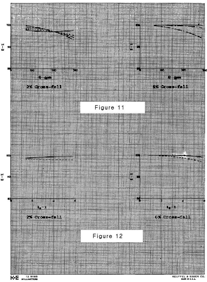
27 APPENDIX Shortly after completion of the foregoing study a sixth grate, the New York grate, was received. Since the Original gutter was still available a set of runs at the same grades and cross-falls as before were carried out on this grate. The New York grate is of welded steel construction as shown in Figure 10. The openings of the grate are approximately 2" in width with dividing members of ¼" x 2 ½" steel plate. Longitudinally the openings of the grate are divided approximately every 4 inches by ¼" x ¾" plates. Upon looking at the grate, one would expect it to be very efficient over a wide range of conditions since the openings are very large in relation to the thickness of material used. The vanes or dividers are not thick enough to allow water to run along them and over the grate. The cross members may, however, cause some obstruction to flow at high velocities. Plots of efficiency vs flow rate, and of efficiency vs longitudinal grade are presented in Figures 11 and 12, respectively, for the trial runs. The curves of Figure 11 have been projected and are thus only estimates of efficiency beyond the flows studied. -21-

28 Figure 10: New York Grate -22-
29 Figure 11 indicates that at a cross-fall of 2% the efficiency was fairly constant at 97 and 99%. Any loss of efficiency here was due to flow by-passing the grate at the low cross-fall. At the 6% cross-fall the efficiency decreased quite rapidly as the velocity and quantity of approaching flow increased. At low longitudinal grades, the grate exhibited efficiencies of 100%, however, as the grade increased to 4 and 6%, the efficiency dropped off rapidly with increasing flow. The observed reason for this was that the flow through the grade was obstructed by the ¾" cross members, causing the flow to jump from cross member to cross member over the grate. At high velocities this effect was highly noticeable. Comparing the efficiency of this grate with the other grates studied, its relative efficiency would appear to lie somewhere in between the Michigan and the DHO-SD-7-74 Modified grates. At low flow velocities its efficiency appears comparable to that of the Rowland grate but as has been stated this high efficiency rapidly declines as flow velocities are increased. Perhaps a slight modification in design of the grate cross members would increase this grate's efficiency to that of the Rowland grate. -23-
30 Figure 11: New York Grate Key E L s Q = efficiency = longitudinal grade = inflow (imperial gallons) Ls = 0.4% L s = 2.0%. Ls = 4.0%.. Ls = 6.0% Figure 12: New York Grate Key E L s Q = efficiency = longitudinal grade = inflow (imperial gallons) Q = 150 gpm Q = 200 gpm -24-
31 -25-
32 -26-
APPENDIX C INLETS. The application and types of storm drainage inlets are presented in detail in this Appendix.
 Storm Drainage 13-C-1 APPENDIX C INLETS 1.0 Introduction The application and types of storm drainage inlets are presented in detail in this Appendix. 2.0 Inlet Locations Inlets are required at locations
CITY UTILITIES DESIGN STANDARDS MANUAL
 CITY UTILITIES DESIGN STANDARDS MANUAL Book 2 (SW) SW7 September 2017 SW7.01 Purpose The purpose of this Chapter is to establish a basis for inlet design utilizing City of Fort Wayne standard inlets and
Highway Drainage 1- Storm Frequency and Runoff 1.1- Runoff Determination
 Highway Drainage Proper drainage is a very important consideration in design of a highway. Inadequate drainage facilities can lead to premature deterioration of the highway and the development of adverse
Chapter 8. Inlets. 8.0 Introduction. 8.1 General
 . Introduction This chapter provides criteria and design guides for evaluating and designing storm sewer inlets in the City of Centennial. The review of all planning submittals will be based on the criteria
Appendix I OFFICE OF THE MORGAN COUNTY SURVEYOR STORMWATER DESIGN MANUAL 7/1/2008
 Appendix I OFFICE OF THE MORGAN COUNTY SURVEYOR This Page Left Intentionally Blank OFFICE OF THE MORGAN COUNTY SURVEYOR APPENDIX I PAGE 1 Appendix II OFFICE OF THE MORGAN COUNTY SURVEYOR This Page Left
STORMWATER CATCHPITS CAPACITY IN NEW ZEALAND BETWEEN THEORY AND PRACTICE
 STORMWATER CATCHPITS CAPACITY IN NEW ZEALAND BETWEEN THEORY AND PRACTICE Husham Issa Al-Saleem Humes Pipeline Systems ABSTRACT New Zealand Territorial Authorities (TA s) infrastructure design standards
PRIVATE STORM DRAINAGE FACILITIES REQUIREMENTS
 PRIVATE STORM DRAINAGE FACILITIES REQUIREMENTS 39 AUGUST 2005 TABLE OF CONTENTS PRIVATE STORM DRAINAGE FACILITIES REQUIREMENTS PAGE SECTION 1 DESIGN CRITERIA 41 SECTION 2 SUBMITTAL 44 SECTION 3 STRUCTURES
RETENTION BASIN EXAMPLE
 -7 Given: Total Tributary Area = 7.5 ac o Tributary Area within Existing R/W = 5.8 ac o Tributary Area, Impervious, Outside of R/W = 0.0 ac o Tributary Area, Pervious, Outside of R/W = 1.7 ac o Tributary
HY-12 User Manual. Aquaveo. Contents
 Y-12 User Manual Aquaveo Contents Overview...2 Watershed Parameters...3 Channel Parameters...3 Storm Drain Parameters...3 Design of new systems...4 Analysis of existing systems...4 Steady flow...4 ydrographic
Catch Basin Inserts: Method to Determine CB Inserts Act as Full Capture Devices
 WATERSHED PROTECTION DIVISION DEPARTMENT OF PUBLIC WORKS BUREAU OF SANITATION CITY OF LOS ANGELES Catch Basin Inserts: Method to Determine CB Inserts Act as Full Capture Devices Catch Basin Inserts: Method
Learn how to design inlet grates, detention basins, channels, and riprap using the FHWA Hydraulic Toolbox and WMS
 v. 11.0 WMS 11.0 Tutorial Learn how to design inlet grates, detention basins, channels, and riprap using the FHWA Hydraulic Toolbox and WMS Objectives Learn how to use several Hydraulic Toolbox calculators
CHAPTER 12 BRIDGE DECK DRAINAGE SYSTEMS
 OFFICE OF STRUCTURES MANUAL FOR HYDROLOGIC AND HYDRAULIC DESIGN CHAPTER 12 BRIDGE DECK DRAINAGE SYSTEMS APRIL 2011 APRIL 2011 Page 1 Chapter Table of Contents 12.1 Policy... 12-3 12.1.1 Table 1... 12-3
Introduction to Storm Sewer Design
 A SunCam online continuing education course Introduction to Storm Sewer Design by David F. Carter Introduction Storm sewer systems are vital in collection and conveyance of stormwater from the upstream
APPENDIX F RATIONAL METHOD
 7-F-1 APPENDIX F RATIONAL METHOD 1.0 Introduction One of the most commonly used procedures for calculating peak flows from small drainages less than 200 acres is the Rational Method. This method is most
CHAPTER 12: DRAINAGE
 CHAPTER 12: DRAINAGE CHINOOK WINDS AND WINTER SNOWS A combination which frequently results in hazardous winter conditions on shaded portions of roadways under bridges. Icing conditions are a danger in
Drainage of Highway Pavements
 PDHonline Course C343 (8 PDH) Drainage of Highway Pavements Instructor: Vincent D. Reynolds, MBA, PE 2012 PDH Online PDH Center 5272 Meadow Estates Drive Fairfax, VA 22030-6658 Phone & Fax: 703-988-0088
بسم هللا الرحمن الرحيم
 بسم هللا الرحمن الرحيم )ملحقات شبكة الصرف الصحي( Class Sewer Appurtenances- 3 rd Dr. Sataa Al-Bayati (10-11) 1. Manholes They are used for inspection & cleaning. They placed when: 1. Intervals between
P d-rain Joint Validation Testing. Final Report. d-rain Validation Testing P Prepared for: Bio-Microbics INC
 Final Report d-rain Validation Testing P16-0028 Prepared for: Bio-Microbics INC By Kansas State University Advanced Manufacturing Institute May 2016 Matthew Campbell Mechanical Engineer 1 P a g e Table
A SUMMARY REPORT OF ARSENIC LEVELS FOUND IN THE MOIRA RIVER WATERSHED
 THE ONTARIO WATER RESOURCES COMMISSION A SUMMARY REPORT OF ARSENIC LEVELS FOUND IN THE MOIRA RIVER WATERSHED April 1970 DIVISION OF INDUSTRIAL WASTES Copyright Provisions and Restrictions on Copying: This
CUYAHOGA COUNTY ENGINEER
 CUYAHOGA COUNTY ENGINEER DRAINAGE MANUAL Supplement to O.D.O.T. LOCATION and DESIGN MANUAL, Volume 2, Drainage Design, Section 1000 and 1100 May 28, 2010 Revisions to the July 29, 2009 edition are noted
Bridge Deck Drainage
 Bridge Deck Drainage Introduction The presence of bridge barriers, curbs, and raised medians impedes the ability of rainfall runoff to drain off of bridge decks into ditch systems, as it does on a typical
APPENDIX G HYDRAULIC GRADE LINE
 Storm Drainage 13-G-1 APPENDIX G HYDRAULIC GRADE LINE 1.0 Introduction The hydraulic grade line is used to aid the designer in determining the acceptability of a proposed or evaluation of an existing storm
CUYAHOGA COUNTY DEPARTMENT OF PUBLIC WORKS CUYAHOGA COUNTY ENGINEER DRAINAGE MANUAL
 CUYAHOGA COUNTY DEPARTMENT OF PUBLIC WORKS CUYAHOGA COUNTY ENGINEER DRAINAGE MANUAL Supplement to O.D.O.T. LOCATION and DESIGN MANUAL, Volume 2, Drainage Design, Section 1000 and 1100 July 29, 2011 Revisions
CHAPTER 12: DRAINAGE
 CHAPTER 12: DRAINAGE Inplace Drainage Structures On projects where inplace manholes or catch basins are likely to be either adjusted or reconstructed, the following additional information is necessary
CUYAHOGA COUNTY DEPARTMENT OF PUBLIC WORKS CUYAHOGA COUNTY ENGINEER DRAINAGE MANUAL
 CUYAHOGA COUNTY DEPARTMENT OF PUBLIC WORKS CUYAHOGA COUNTY ENGINEER DRAINAGE MANUAL Supplement to O.D.O.T. LOCATION and DESIGN MANUAL, Volume 2, Drainage Design, Section 1000 and 1100 November 18, 2013
DRAINAGE & DESIGN OF DRAINAGE SYSTEM
 Drainage on Highways DRAINAGE & DESIGN OF DRAINAGE SYSTEM P. R.D. Fernando Chartered Engineer B.Sc.(Hons), M.Eng. C.Eng., MIE(SL) Drainage Requirement of Highway Drainage System Introduction Drainage means
The Most Advanced Name in Water Management Solutions TM. The most cost-effective slotted and trench surface drain systems.
 The Most Advanced Name in Water Management Solutions TM The most cost-effective slotted and trench surface drain systems. A sensible alternative to metal and concrete Since 1987, Duraslot surface drains
PERFORMANCE OF FLOATING HORIZONTAL AERATORS IN AERATED LAGOONS AND OXIDATION DITCHES
 PERFORMANCE OF FLOATING HORIZONTAL AERATORS IN AERATED LAGOONS AND OXIDATION DITCHES PRESENTED ON WEDNESDAY, APRIL 4, 2001 AT THE TEXAS WATER 2001 ANNUAL CONFERENCE LARRY W. MOORE CIVIL ENGINEERING DEPARTMENT
FORMULATION OF NOMOGRAPH FOR INLETS OF ZERO DEPRESSION ABSTRACT
 FORMULATION OF NOMOGRAPH FOR INLETS OF ZERO DEPRESSION Ojo, O. O. & Akinboboye, V.A. Dept of Civil Engineering Technology, Rufus Giwa Polytechnic Owo NIGERIA ABSTRACT The formulation of the nomograph entails
Stormwater Treatment Measure Sizing and Design Considerations SMCWPPP C.3 Workshop June 21, 2017
 Stormwater Treatment Measure Sizing and Design Considerations SMCWPPP C.3 Workshop June 21, 2017 Jill Bicknell, P.E., EOA, Inc. Presentation Overview Sizing/Design of Self Treating and Self Retaining Areas
Chapter 9 - Storm Drains
 Chapter 9 - Storm Drains TABLE OF CONTENTS CHAPTER 9 - STORM DRAINS... 9-1 9.1 Introduction... 9-1 9.1.1 Objective 9-1 9.2 Design Policy... 9-2 9.2.1 Definition 9-2 9.2.2 General Policies... 9-2 9.3 Design
South Diversion Channel Project
 Physical Modeling Report II October 23, 2009 South Diversion Channel Project Recommendations on Flow Diversion System and Structures Based on Physical Model Studies at UNM Hydraulics Laboratory Prepared
MultiDrain Systems, Inc. #8 EconoDrain and EconoDrain PT-3 Hydraulic Data. We drain your site, not your budget!
 #8 EconoDrain and EconoDrain PT-3 Hydraulic Data MultiDrain Systems, Inc. We drain your site, not your budget! Copyright July 2008 MultiDrain Systems, Inc. System and Hydraulic Data: # 8 EconoDrain and
December 6, Nate Hatleback Project Manager City of Thornton 9500 Civic Center Drive Thornton, CO 80229
 December 6, 2016 Nate Hatleback Project Manager City of Thornton 9500 Civic Center Drive Thornton, CO 80229 RE: Drainage Conformance Letter Hilton Garden Inn @ The Grove The Grove Filing No 1, lot 5E Thornton,
MAXFLOW GRATE 0.25% - 1% 4% - 8% 12% 16% Capture L/s. Approach Flow L/s
 MAXFLOW GRATE 8.25% - 7-6 5 4 3 2 1 5 1 15 2 25 CONTENTS DRAINWAY Introduction Page 2 Precast Units Page 3 Maxflow Grate Page 4 Mannflow Grate Page 6 Draincover Page 8 Sag Capture Page 1 Conversion Factors
Appendix J: Storm Conveyance Design Parameters
 Appendix J: Storm Conveyance Design Parameters Drain Commissioner 39 February 2005 STORM DRAINAGE DESIGN CRITERIA A. STORM SEWERS 1. The required discharge capacity shall be determined by the Rational
November 21, City of Thornton 9500 Civic Center Drive Thornton, CO (303) RE: Maverik Thornton, CO - Drainage Report
 RE: Maverik Thornton, CO - Drainage Report") November 21, 2016 City of Thornton 9500 Civic Center Drive Thornton, CO 80229 (303) 538-7295 RE: Maverik Thornton, CO - Drainage Report As per your request, we are submitting to you the drainage report
November 21, 2016 City of Thornton 9500 Civic Center Drive Thornton, CO 80229 (303) 538-7295 RE: Maverik Thornton, CO - Drainage Report As per your request, we are submitting to you the drainage report
PHOSPHORUS REDUCTION BY ALGAL CULTURES DIVISION OF RESEARCH ONTARIO WATER RESOURCES COMMISSION
 PHOSPHORUS REDUCTION BY ALGAL CULTURES DIVISION OF RESEARCH ONTARIO WATER RESOURCES COMMISSION March, 1967 Res. Paper 2004 Copyright Provisions and Restrictions on Copying: This Ontario Ministry of the
Hydrologic Study Report for Single Lot Detention Basin Analysis
 Hydrologic Study Report for Single Lot Detention Basin Analysis Prepared for: City of Vista, California August 18, 2006 Tory R. Walker, R.C.E. 45005 President W.O. 116-01 01/23/2007 Table of Contents Page
3.0 STORM DRAINAGE SYSTEM DESIGN
 SPALDING COUNTY, GEORGIA CHAPTER 3 3.0 STORM DRAINAGE SYSTEM DESIGN... 3-1 3.1 OVERVIEW... 3-1 3.1.1 INTRODUCTION... 3-1 3.1.2 DRAINAGE SYSTEM COMPONENTS... 3-1 3.1.3 INLET AND STORM DRAIN PIPE DESIGN...
Chapter 7. Street Drainage. 7.0 Introduction. 7.1 Function of Streets in the Drainage System. 7.2 Street Classification
 7. Introduction This chapter summarizes methods to evaluate runoff conveyance in various street cross sections and curb types in the Town of Castle Rock and identifies acceptable upper limits of street
SECTION CONCRETE CURBS, GUTTERS AND SIDEWALKS. A. Formwork complete with shoring, bracing and anchorage.
 SECTION 02528 CONCRETE CURBS, GUTTERS AND SIDEWALKS PART 1 GENERAL 1.01 WORK INCLUDED A. Formwork complete with shoring, bracing and anchorage. B. Concrete reinforcement complete with required supports,
County of Sacramento Standard Construction Specifications January 1, 2008 TECHNICAL PROVISIONS
 County of Sacramento Standard Construction Specifications January 1, 2008 TECHNICAL PROVISIONS SECTION 27 CURBS, GUTTERS, SIDEWALKS, AND DRAINAGE STRUCTURES 27-1 GENERAL Concrete curbs, gutters, sidewalks,
RE: Final Drainage Letter: Northwest Aurora Alley Improvements 2016
 April 12, 2016 Mr. Craig Perl, P.E. Senior Engineer City of Aurora Public Works Department 15151 E. Alameda Parkway Aurora, CO 80012 RE: Final Drainage Letter: Northwest Aurora Alley Improvements 2016
APPENDIX F DESIGN CRITERIA FOR STORM WATER DRAINAGE FACILITIES (1.10 of Appendix A)
") APPENDIX F 1.10 DESIGN CRITERIA FOR STORM WATER DRAINAGE FACILITIES (1.10 of Appendix A) SECTION 1 INTRODUCTION 1.01 Purpose The purpose of this manual is to establish standard methods and principals for
APPENDIX F 1.10 DESIGN CRITERIA FOR STORM WATER DRAINAGE FACILITIES (1.10 of Appendix A) SECTION 1 INTRODUCTION 1.01 Purpose The purpose of this manual is to establish standard methods and principals for
FORT COLLINS STORMWATER CRITERIA MANUAL Hydrology Standards (Ch. 5) 1.0 Overview
 1.0 Overview") Chapter 5: Hydrology Standards Contents 1.0 Overview... 1 1.1 Storm Runoff Determination... 1 1.2 Design Storm Frequencies... 1 1.3 Water Quality Storm Provisions... 2 1.4 Design Storm Return Periods...
Chapter 5: Hydrology Standards Contents 1.0 Overview... 1 1.1 Storm Runoff Determination... 1 1.2 Design Storm Frequencies... 1 1.3 Water Quality Storm Provisions... 2 1.4 Design Storm Return Periods...
TRENCH FORMER. ABT, INC., 259 Murdock Road, Troutman NC 28166, (800)
") DESIGN GUIDE POLYDRAIN TRENCH FORMER INTERCEPTOR ABT, INC., 259 Murdock Road, Troutman NC 28166, www.abtdrains.com, (800)438-6057 DISCLAIMER: The customer and the customer s architects, engineers, consultants
DESIGN GUIDE POLYDRAIN TRENCH FORMER INTERCEPTOR ABT, INC., 259 Murdock Road, Troutman NC 28166, www.abtdrains.com, (800)438-6057 DISCLAIMER: The customer and the customer s architects, engineers, consultants
MultiDrain Systems, Inc. #12 EconoDrain and EconoDrain PT-3 Hydraulic Data. We drain your site, not your budget!
 #12 EconoDrain and EconoDrain PT-3 Hydraulic Data MultiDrain Systems, Inc. We drain your site, not your budget! Copyright July 2008 MultiDrain Systems, Inc. System and Hydraulic Data: # 12 EconoDrain and
ITEM 6 CONCRETE CURBS, GUTTERS, AND SIDEWALKS
 ITEM 6 CONCRETE CURBS, GUTTERS, AND SIDEWALKS 6.1 DESCRIPTION This work shall consist of constructing curbs, gutters, sidewalks, ramps, local depressions and driveways of the form and dimensions shown
Current Standard Plates including Transmittal Letters are available on the web at:
 MINNESOTA DEPARTMENT OF TRANSPORTATION DEVELOPED BY: Design Standards ISSUED BY: Office of Project Management and Technical Support, Design Support Section TRANSMITTAL LETTER NO. (6-03) MANUAL: Standard
PERKFILTER. Design Guide
 PERKFILTER Design Guide TABLE OF CONTENTS Description Function Treatment Processes System Hydraulics System Sizing PerkFilter Configurations Inspection and Maintenance Requirements Verification and Approvals
The site slopes generally from the southwest to northeast at approximately 3.7 percent.
 March 3, 2017 Nate Hatleback Project Manager, City of Thornton Development Engineering 9500 Civic Center Drive Thornton, CO 80229 (303) 538-7694 RE: Riverdale Five Retail Drainage Conformance Letter Dear
Sump Pumps Office procedures for the Drainage & Grading section
 County of Los Angeles Department of Public Works Building and Safety Division Grading and Drainage Section Sump Pumps Office procedures for the Drainage & Grading section Introduction This manual provides
SECTION CURB, COMBINATION CURB AND GUTTER, AND MONOLITHIC MEDIAN. 1. Bituminous concrete pavement; Section
 02670-1 of 6 SECTION 02670 CURB, COMBINATION CURB AND GUTTER, AND 02670.01 GENERAL A. Description This work shall include, but not necessarily be limited to, the construction of concrete curb, concrete
TECHNICAL BULLETIN. Synthetic Turf Athletic Field Drainage Design Assistance
 TECHNICAL BULLETIN Synthetic Turf Athletic Field Drainage Design Assistance The SportsEdge HQ geocomposite strip drain products are engineered specifically for use in synthetic turf athletic field base
City of Regina Standard Construction Specification SECTION 2350 PLACEMENT OF ASPHALTIC CONCRETE SURFACE 1.0 GENERAL. 1.1 Scope
 1.0 GENERAL 1.1 Scope 2.0 PRODUCTS 1.1.1 The work shall consist of placing asphaltic concrete to a compacted thickness conforming to the lines, grades, and cross-sections as shown on the plan or as designated
Pre-Sloped Drain System
 SportsEdge PolyDrain Pre-Sloped Drain System www.sportsedge.com Quality. Safety. Versatility. Aesthetics. 2 PolyDrain FORMULA www.sportsedge.com ABT, Inc. manufactures PolyDrain trench drains; the standard
Chapter 11 Culverts and Bridges
 Chapter 11 Culverts and Bridges Contents 1.0 Introduction... 1 2.0 General Design... 1 2.1 Design Criteria... 1 2.2 Design Flows... 1 2.3 Permitting and Regulations... 1 2.4 Aesthetics and Safety... 2
STORM AND SURFACE WATER 4-1 GENERAL...4-1
 SECTION 4 STORM AND SURFACE WATER SECTION DESCRIPTION PAGE 4-1 GENERAL...4-1 4-2 STORM DRAINAGE CONVEYANCE SYSTEM DESIGN CRITERIA...4-1 4-2.1 Overview...4-1 4-2.2 Design Flow and Route Requirements...4-2
Index. outlet protection Rev. 12/93
 6 Index outlet protection level spreader outlet stabilization structure 6.40.1 6.41.1 Rev. 12/93 Practice Standards and Specifications 6.40 level spreader Definition Purpose Conditions Where Practice Applies
Trench Former 7 MD200 TM / 300 TM
 Trench Former 7 MD200 TM / 300 TM... Trench Drain Forming System ROADS AND HIGHWAYS COMMERCIAL AND INDUSTRIAL SITES AND LOADING DOCKS www.abtdrains.com... Today s Hydraulic Solutions Advanced Building
Basic Types of Irrigation Systems. Surface irrigation Subsurface irrigation Sprinkler irrigation Drip/trickle irrigation
 Irrigation systems Basic Types of Irrigation Systems Surface irrigation Subsurface irrigation Sprinkler irrigation Drip/trickle irrigation Subsurface Irrigation Also call subirrigation Artificial regulation
EXTENDED DETENTION BASIN EXAMPLE
 EXTENDED DETENTION BASIN EXAMPLE 1117 6 July 2015 REFERENCE SECTION 1117 Given: TotalTributaryArea=7.5 o TributaryAreawithinExistingR/W=7.2 o TributaryArea,Impervious,OutsideofR/W=0.3 o TributaryArea,Pervious,OutsideofR/W=0.0
1. Division 01 Section General Requirements - Temporary Facilities and Controls. 2. Division 31 Section Earthwork.
 PAGE 334000-1 SECTION 334000 PART 1 - GENERAL 1.1 RELATED DOCUMENTS A. Drawings and general provisions of the Contract, including General and Supplementary Conditions and Division 01 Specification sections,
The Most Advanced Name in Water Management Solutions TM. The most cost-effective slotted and trench surface drain systems.
 The Most Advanced Name in Water Management Solutions TM The most cost-effective slotted and trench surface drain systems. A sensible alternative to metal and concrete Since 1987, Duraslot surface drains
CONSTRUCTION SPECIFICATION FOR CONCRETE CURB AND GUTTER SYSTEMS
 ONTARIO PROVINCIAL STANDARD SPECIFICATION METRIC OPSS 353 NOVEMBER 2010 CONSTRUCTION SPECIFICATION FOR CONCRETE CURB AND GUTTER SYSTEMS TABLE OF CONTENTS 353.01 SCOPE 353.02 REFERENCES 353.03 DEFINITIONS
CONSTRUCTION SPECIFICATION FOR CONCRETE CURB AND GUTTER SYSTEMS
 ONTARIO PROVINCIAL STANDARD SPECIFICATION METRIC OPSS 353 NOVEMBER 2006 CONSTRUCTION SPECIFICATION FOR CONCRETE CURB AND GUTTER SYSTEMS TABLE OF CONTENTS 353.01 SCOPE 353.02 REFERENCES 353.03 DEFINITIONS
DRAINAGE TABLE OF CONTENTS CHAPTER 22
 TABLE OF CONTENTS CHAPTER FILE NO. TITLE DATE TABLE OF CONTENTS AND INTRODUCTION.TOC-1 Table of Contents - Chapter... 6Sept01.TOC- Table of Contents - Chapter... 01Jul011.TOC-3 Table of Contents - Chapter...
Hydrology Study. Ascension Heights Subdivision Ascension Drive at Bel Aire Road San Mateo, California (Unincorporated)
") Hydrology Study Ascension Heights Subdivision Ascension Drive at Bel Aire Road San Mateo, California (Unincorporated) Prepared for San Mateo Real Estate & Construction March 9, 21 Rev. 1 11-8-211 Rev.
Hydrology Study Ascension Heights Subdivision Ascension Drive at Bel Aire Road San Mateo, California (Unincorporated) Prepared for San Mateo Real Estate & Construction March 9, 21 Rev. 1 11-8-211 Rev.
Section 403. DRAINAGE STRUCTURES
 403.01 Section 403. DRAINAGE STRUCTURES 403.01. Description. This work consists of adjusting, constructing, or temporarily lowering drainage structures and cleaning existing drainage structures and leads
14. SCREENS. in the Figure 8.1. BARS TROUGH
 1 14. SCREENS The primary treatment incorporates unit operations for removal of floating and suspended solids from the wastewater. They are also referred as the physical unit operations. The unit operations
Chapter 9 STORMWATER DESIGN. Table 9-1 Hydrology Design Methods
 www.knoxvilletn.gov/engineering/ 9.1 Hydrology Methods Chapter 9 STORMWATER DESIGN Table 9-1 shows the various hydrologic computation methods that can be used to compute peak flows in the City of Knoxville.
(b) Discuss in brief shaft spillway with neat sketches. Marks 04. OR Q (2) Explain in brief USBR stilling basin. Marks 08
 Discuss in brief shaft spillway with neat sketches. Marks 04. OR Q (2) Explain in brief USBR stilling basin. Marks 08") (b) Discuss in brief shaft spillway with neat sketches. Marks 04 OR Q (2) Explain in brief USBR stilling basin. Marks 08 Stilling Basins The basins are usually provided with special appurtenances including
(b) Discuss in brief shaft spillway with neat sketches. Marks 04 OR Q (2) Explain in brief USBR stilling basin. Marks 08 Stilling Basins The basins are usually provided with special appurtenances including
Report. Inflow Design Flood Control System Plan St. Clair Power Plant St. Clair, Michigan. DTE Energy Company One Energy Plaza, Detroit, MI
 Report Inflow Design Flood Control System Plan St. Clair Power Plant St. Clair, Michigan DTE Energy Company One Energy Plaza, Detroit, MI October 14, 2016 NTH Project No. 62-160047-04 NTH Consultants,
January 20, Nate Hatleback Project Manager, City of Thornton Development Engineering 9500 Civic Center Drive Thornton, CO (303)
") January 20, 2017 Nate Hatleback Project Manager, City of Thornton Development Engineering 9500 Civic Center Drive Thornton, CO 80229 (303) 538-7694 RE: Riverdale Five Retail Drainage Conformance Letter
January 20, 2017 Nate Hatleback Project Manager, City of Thornton Development Engineering 9500 Civic Center Drive Thornton, CO 80229 (303) 538-7694 RE: Riverdale Five Retail Drainage Conformance Letter
Bioreactor Landfill Design
 Bioreactor Landfill Design Timothy Townsend, PhD, PE Department of Environmental Engineering Sciences University of Florida ttown@ufl.edu Bioreactor Landfill Design Modern landfill design entails many
Screening, Definition: The unit involved is called a screen.
 Screening, Definition: Screening is a unit operation that separates materials in and/or on water (found in different sizes) from water and from entering water treatment facilities and mains. The unit involved
PROPOSED THREE-STOREY RESIDENTIAL APARTMENT BUILDING SITE LOT 19 R-PLAN ROCKINGHAM AVENUE CITY OF OTTAWA STORM DRAINAGE REPORT
 PROPOSED THREE-STOREY RESIDENTIAL APARTMENT BUILDING SITE LOT 19 R-PLAN 149 1162 ROCKINGHAM AVENUE CITY OF OTTAWA STORM DRAINAGE REPORT REPORT No. R-815-41 T. L. MAK ENGINEERING CONSULTANTS LTD. JUNE 2015
ENGINEERED SOLUTIONS. CDS Guide Operation, Design, Performance and Maintenance
 ENGINEERED SOLUTIONS CDS Guide Operation, Design, Performance and Maintenance CDS Design Basics Using patented continuous deflective separation technology, the CDS system screens, separates and traps debris,
ENGN.4010 ENGINEERING CAPSTONE DESIGN Watershed Analysis. CiA
 RATIONAL METHOD Q CiA Where: Q = Maximum Rate of Runoff (cfs) C = Runoff Coefficient i = Average Rainfall Intensity (in/hr) A = Drainage Area (in acres) RATIONAL METHOD Assumptions and Limitations: Watershed
The SuDS Manual Frequently asked questions
 The SuDS Manual Frequently asked questions 1. Is source control still a requirement of the new SuDS Manual? Yes. Source control components are fundamental elements of a SuDS scheme. The benefits of source
HERPIC County Storm Drainage Manual
 HERPIC County Storm Drainage Manual C h r is t o p h e r B. B u r k e Research Assistant Highway Extension and Research Project for Indiana Counties Purdue University The HERPIC (Highway Extension and
TraffikDrain. 2 bolts per half meter grates for removable grate option
 ACO ROAD TraffikDrain Eup to 2,788 psi Typical Applications Urban areas Highways Interstates State roads 2 bolts per half meter grates for removable grate option Ductile iron USA Made grate provides 60%
Extended Detention Basin Design
 Extended Detention Basin Design 1 Extended Detention 2 Ohio Department of Transportation 1 Extended Detention Basin L&D Vol. 2 Section 1117.3 Provides quality and quantity treatment 3 Extended Detention
Precast Concrete Trench Drain Systems INSTALLATION INSTRUCTIONS
 Precast Concrete Trench Drain Systems INSTALLATION INSTRUCTIONS GENERAL INSTALLATION INSTRUCTIONS 1 Ensure that the trench where the channels are going to be installed has enough room for the appropriate
HYDRAULIG PERFORMANCE OF PENNSYLVANIA HIGHWAY DRAINAGE rulets INSTALLED IN PAVED CHA~LS
 Nor FCR l:ublication Cj\J Gi r~leer;t J1\1G L/[,tfI.Al\ HYDRAULIG PERFORMANCE OF PENNSYLVANIA HIGHWAY DRAINAGE rulets INSTALLED IN PAVED CHA~LS by Arthur W. Brune, Associate Professor, Lehigh University,
Warner Robins Stormwater Local Design Manual
 Warner Robins Stormwater Local Design Manual Prepared for Houston County City of Warner Robins City of Perry City of Centerville May 17, 2005 Version 4 (As presented with adopted Stormwater Ordinance)
HYDROLOGIC-HYDRAULIC STUDY ISABELLA OCEAN RESIDENCES ISLA VERDE, CAROLINA, PR
 HYDROLOGIC-HYDRAULIC STUDY ISABELLA OCEAN RESIDENCES ISLA VERDE, CAROLINA, PR 1 INTRODUCTION 1.1 Project Description and Location Isabella Ocean Residences is a residential development to be constructed
1. Overview 2 2. Definitions 2 3. Laboratory Testing Criteria 2. A. Laboratory Qualifications 2. B. Analysis of TSS Samples 2. C.
 New Jersey Department of Environmental Protection Laboratory Protocol to Assess Total Suspended Solids Removal by a Hydrodynamic Sedimentation Manufactured Treatment Device January 25, 2013 Contents 1.
Inlet Protection. Fe= (Depends on soil type)
") 3.4 DESIGN CRITERIA: KEY CONSIDERATIONS Evaluate drainage patterns to ensure inlet protection will not cause flooding of roadway, property or structures Never block entire inlet opening Size according
3.4 DESIGN CRITERIA: KEY CONSIDERATIONS Evaluate drainage patterns to ensure inlet protection will not cause flooding of roadway, property or structures Never block entire inlet opening Size according
WMS 8.4 Tutorial Storm Drain Modeling Storm Drain: Hydrographic Design Learn how to run sub-basin hydrographs through a storm drain network
 v. 8.4 WMS 8.4 Tutorial Storm Drain Modeling Storm Drain: Hydrographic Design Learn how to run sub-basin hydrographs through a storm drain network Objectives Build a rational method model and compute sub-basin
Chapter 5 Hydraulic Structures
 Chapter 5 Hydraulic Structures 5.1 Flow Splitter Designs 5.1.1 General Design Criteria A flow splitter must be designed to deliver the WQ design flow rate specified in this volume to the WQ treatment facility.
AMENDMENTS TO OPSS 408 (OCT 89) CONSTRUCTION SPECIFICATION FOR ADJUSTING OR REBUILDING MANHOLES, CATCH BASINS, DITCH INLETS AND VALVE CHAMBERS
 CONSTRUCTION SPECIFICATION FOR ADJUSTING OR REBUILDING MANHOLES, CATCH BASINS, DITCH INLETS AND VALVE CHAMBERS") Works and Emergency Services CITY OF TORONTO WATER AND WASTEWATER SERVICES STANDARD CONSTRUCTION SPECIFICATIONS TS 408 November 2010 AMENDMENTS TO OPSS 408 (OCT 89) CONSTRUCTION SPECIFICATION FOR ADJUSTING
Works and Emergency Services CITY OF TORONTO WATER AND WASTEWATER SERVICES STANDARD CONSTRUCTION SPECIFICATIONS TS 408 November 2010 AMENDMENTS TO OPSS 408 (OCT 89) CONSTRUCTION SPECIFICATION FOR ADJUSTING
WMS 9.1 Tutorial Storm Drain Modeling Storm Drain: Hydrographic Design Learn how to run sub-basin hydrographs through a storm drain network
 v. 9.1 WMS 9.1 Tutorial Storm Drain Modeling Storm Drain: Hydrographic Design Learn how to run sub-basin hydrographs through a storm drain network Objectives Build a rational method model and compute sub-basin
TESTS OF CARGO FLOORING Nn AND T FOP AIRCRAFT
 TESTS OF CARGO FLOORING Nn AND T FOP AIRCRAFT Information Reviewed and Reaffirmed March 1956 No. 1550-E LOAN COPY Please return to: Wood Engineering Research Forest Products Laboratory Madison, Wisconsin
CITY OF WAXAHACHIE, TEXAS MANUAL FOR THE DESIGN OF STORM DRAINAGE SYSTEMS
 CITY OF WAXAHACHIE, TEXAS MANUAL FOR THE DESIGN OF STORM DRAINAGE SYSTEMS MAY, 2001 TABLE OF CONTENTS Page No. SECTION I: INTRODUCTION 1.1 General... I-1 1.2 Scope... I-1 1.3 Organization of Manual...
3.11 Sand Filter Basin
 3.11 Sand Filter Basin Type of BMP Priority Level Treatment Mechanisms Maximum Drainage Area Flow-Through Treatment Priority 3 Treatment Control BMP Filtration 25 acres Description The Sand Filter Basin
Installation Instructions
 EconoDrain Trench Forming System Installation Instructions MultiDrain We Drain Your Site, Not Your Budget MultiDrain Systems, Inc. P.O. Box 88, Barium Springs, NC 28010 (704) 508-1010 or Toll Free 800-433-1119
The critical information from this document has been included in the ARD Pipe Help system.
 Introduction This command is used to set the way is treated with respect to Pipe flow. There are three (3) methods, along with the ability to change the method on existing networks. flows have always been