Introduction to Storm Sewer Design
|
|
|
- Randell Hancock
- 6 years ago
- Views:
Transcription
1 A SunCam online continuing education course Introduction to Storm Sewer Design by David F. Carter
2 Introduction Storm sewer systems are vital in collection and conveyance of stormwater from the upstream contributing watershed area to a receiving downstream water body such as a lake or stormwater facility. Proper design of this system is essential in avoiding upstream flooding, erosion and sediment transport. A working knowledge of hydrology and hydraulics is required to produce an efficient design that prevents creation of adverse impacts. This course intends to provide the user with the basic tools needed to achieve the desired end result - a cost efficient and environmentally effective design. Rational Method System hydrology is usually analyzed using the Rational Method which is expressed in the equation: Where: Q = C x I x A Q = Peak runoff rate for a design return period (frequency) in cubic feet per second (cfs) C = Runoff coefficient for a design return period expressed as the dimensionless ratio of rainfall excess to total rainfall I = Rainfall intensity in inches per hour during a period of time equal to the time of concentration for the design return period. This value can be taken from an Intensity-Duration-Frequency (IDF) curve for the location being analyzed or computed from an equation derived from same. Tc = Time of concentration for the longest flow path in the contributing watershed area, in minutes, used to determine I A = Contributing watershed drainage area, in acres, tributary to the design point The usual procedure for calculating the time of concentration for a watershed involves at least three types of flow: overland or sheet, shallow concentrated and open channel. One acceptable way to account for each of these types of flow is through an approach that considers the average velocity for each particular flow segment. This method requires calculating a travel time using the equation: Copyright 2010 David F. Carter 2 of 20
3 Where: t= i L/(60)v i i t i = Travel time for velocity segment i, in minutes L i = Length of the flow path for segment i, in feet v i = Average velocity for segment i, in ft/sec The time of concentration is then calculated as: t c = t 1 + t 2 + t t i Where: t c = Time of concentration, in minutes t 1 = Overland flow travel time, in minutes t 2 = Shallow concentrated travel time, in minutes t 3 = Open channel travel time, in minutes t i = Travel time for the i th segment, in minutes Overland flow travel times can be evaluated using Figure 1-Overland Flow Velocities for Various Land Use Types to obtain an estimate of the average velocity following these steps: 1. Using available topographic and aerial mapping, determine the average slope of the overland flow path, in percent, and identify the land use cover. 2. Enter the x-axis with the average slope from Step 1 and run a vertical line to the curve which represents the land use cover of the overland flow path. 3. Run a horizontal line from the point of intersection determined in Step 2 to the y-axis and read the overland flow velocity in feet per minute. 4. Convert the velocity obtained in Step 3 to feet per second by dividing by Use the above equation to calculate the overland flow time (t 1 ). Copyright 2010 David F. Carter 3 of 20

4 Figure 1 Overland Flow Velocities for Various Land Use Types Copyright 2010 David F. Carter 4 of 20
5 Shallow concentrated flow travel times can be evaluated using Figure 2-Shallow Concentrated Flow Velocities to obtain an estimate of the average velocity following these steps: 1. Using available topographic mapping, determine the average slope of the shallow concentrated flow path, in percent, and determine whether it is rill or gutter flow. 2. Enter the y-axis with the average slope from Step 1 and run a horizontal line to the curve which represents either rill or shallow gutter flow. 3. Run a vertical line from the point of intersection determined in Step 2 to the x- axis and read the shallow concentrated flow velocity in feet per second 4. Use the above equation to calculate the shallow concentrated flow time (t 2 ). Other types of shallow concentrated flow, as well as open channel flow, can be evaluated using Manning s Equation. Manning s Equation System hydraulics is usually analyzed using Manning s Equation: Where: Q = (1.49/n) x A x 2/3 R x S Q = Discharge rate for design conditions in cfs n = Manning s roughness coefficient (dimensionless) A = Cross-sectional area of conduit in square feet R = Hydraulic radius A/P in feet. For a circular channel flowing either full or halffull, the hydraulic radius is D/4 where D is the diameter. P = Wetted perimeter in feet, used to determine the hydraulic radius R S = Slope of the energy grade line in ft/ft Copyright 2010 David F. Carter 5 of 20
 www.suncam.com Copyright 2010 David F.")
6 Figure 2 Shallow Concentrated Flow Velocities Reference: USDA< SCS, TR-55 Draft (1984) Copyright 2010 David F. Carter 6 of 20
7 Storm Sewer Tabulations Table 1-Storm Sewer Tabulation, is an example of a storm sewer tabulation form recommended for tabulating the results of hydrologic and hydraulic calculations for storm drain systems. Design of this system usually follows these steps: 1. Select inlet locations and develop preliminary plan. 2. Conduct hydrologic calculations to determine design flow rates. 3. Conduct hydraulic calculations to determine culvert sizes needed to convey flow rates determined in Step Design outfall including required retention/detention facility with the goal of dissipating energy to prevent erosion and sediment transport. The parameters to be recorded on this form are described below: Runoff Coefficients (C) Available literature abounds with tables giving runoff coefficient values based on land use, soil type and watershed slope. Table 2-Runoff Coefficients for a Design Storm Return Period of 10 Years or Less gives such values for a design storm return period of 10 years or less. It is customary in many areas to design storm sewers based on the 5-year return period. For return periods longer than 10 years, a design storm frequency factor is applied. The designer has the choice of using a single coefficient value or different values for high and low coefficient areas contributing runoff to a specific inlet. For example, a highly impervious area would have a higher coefficient than a low impervious area such as a park. A combined business/park area might be 60 percent high and 40 percent low. A summary of runoff coefficient determinations for the example project appears in Table 3-Runoff Coefficients. Likewise, a summary of hydrologic parameters appears in Table 4-Hydrologic Parameters. Copyright 2010 David F. Carter 7 of 20
8 Table 1 FRANKLIN WOODS STORM SEWER TABULATION BY: CARTER STRUCT. STRUCT. LENGTH DRAINAGE AREA (AC.) MANHOLE ELEV. OF H.G. Notes TYPE NO. (FT) C= 0.4 TIME OF OR CROWN ELEVATION Florida Zone 4 IDF C= 0.2 SUB Tc FLOW TOTAL Q INLET FLOW LINE EL. 5 Year Storm C= TOTAL (MIN.) IN INTENSITY (CA) TOTAL TOP UPPER LOWER FALL DIAM. SLOPE Velocity Capacity 1 foot minimum cover INCRE- SUB (CA.) SECTION (IN/HR) RUNOFF ELEVATION (FT.) (IN.) (%) (fps) (CFS) MENT TOTAL (MIN) (CFS) (FT.) Remarks TYPE Minor Loss = " C.I. S Loss Coeff. = " C.I. S RCP COVER = 1.57 TYPE Minor Loss = " C.I. S Loss Coeff. = 0.60 "J" MH S-2A HDPE COVER = 1.43 TYPE Minor Loss = " C.I. S Loss Coeff. = 0.50 "J" MH S-2A RCP COVER = 1.74 TYPE Minor Loss = 0.03 "J" M.H. S-2A Loss Coeff. = " C.I. S HDPE COVER = 1.70 TYPE Minor Loss = " C.I. S Loss Coeff. = " C.I. S RCP COVER = 1.75 TYPE Minor Loss = " C.I. S Loss Coeff. = 0.80 "J" MH S-5A RCP COVER = 1.80 TYPE Minor Loss = 0.02 "J" M.H. S-5A Loss Coeff. = " C.I. S HDPE COVER = 2.67 TYPE Minor Loss = " C.I. S Loss Coeff. = 0.80 "J" MH S-6A HDPE COVER = 2.29 TYPE Minor Loss = 0.02 "J" M.H. S-6A Loss Coeff. = " M.E.S. S-6B HDPE COVER = Copyright 2010 David F. Carter 8 of 20
9 Copyright 2010 David F. Carter 9 of 20
10 Runoff Structure Basin Slope Land Use Soil Type Coefficient S-1 B-1A Flat (0-2%) *SFR: 1/4-acre lots Sandy 0.4 B-1B Flat (0-2%) pasture Sandy 0.2 S-2 B-2 Flat (0-2%) SFR: 1/4-acre lots Sandy 0.4 S-3 B-3 Flat (0-2%) SFR: 1/4-acre lots Sandy 0.4 S-4 B-4 Flat (0-2%) SFR: 1/4-acre lots Sandy 0.4 S-5 B-5 Flat (0-2%) SFR: 1/4-acre lots Sandy 0.4 S-6 B-6 Flat (0-2%) SFR: 1/4-acre lots Sandy 0.4 * SFR = Single Family Residential Table 3 Runoff Coefficients Drainage *Time of Rainfall Inlet Area Concentration Intensity Runoff Flow Rate Structure Type (acres) (min) (in/hr) Coefficient (cfs) S-1 curb inlet S-2 curb inlet S-2A manhole 0 NA NA NA NA S-3 curb inlet S-4 curb inlet S-5 curb inlet S-5A manhole 0 NA NA NA NA S-6 curb inlet S-6A manhole 0 NA NA NA NA S-6B mitered end section 0 NA NA NA NA TOTAL 5.48 Table 4 Hydrologic Parameters * This is the time of concentration for the longest hydraulic flow time to that particular point including overland flow, gutter flow (if applicable) and sewer flow. Copyright 2010 David F. Carter 10 of 20
11 Notes: Data related to the system such as rainfall zone, storm event frequency, minimum cover for culverts, etc. should appear here. Structure Type This data is usually given in abbreviated format such as C.I for curb inlet, D.B.I for ditch bottom inlet and J M.H. for type J manhole. Structure Number This is a unique identifier giving the sequential numbers of the drainage structures in the system. A common convention is to number them in ascending order from upstream to downstream. That is, the outfall might be S-10 while the upstream most structure might be S-1. Refer to Figure 3-Storm Sewer Schematic for an example storm sewer schematic. Length The distance in feet from the centerline of the structure in question to the centerline of the next structure. Since pipe is manufactured in standard 8-foot lengths, it is best practice to try to design the system using this incremental length if possible. Increment This is the incremental area contributing runoff to the inlet in question. Manholes have no incremental area as no runoff is being collected at that point. Subtotal This is the subtotal of all the incremental areas contributing runoff through the structure in question. Subtotal (CA) This is the subtotal of the contributing incremental areas multiplied by its respective runoff coefficient. Copyright 2010 David F. Carter 11 of 20
12 Figure 3 Storm Sewer Schematic Copyright 2010 David F. Carter 12 of 20
13 Tc (min) This is the time of concentration required for the flow contribution to travel from the most upstream point of the contributing drainage area to that particular point of the system. This time includes the initial overland flow and gutter flow plus the flow time within the sewer system. Time of Flow in Section (min) This is the flow time for the section of pipe in question. Intensity Values for this parameter depend on the design frequency and the time of concentration. If taken from an intensity-duration-frequency (IDF) curve, it is the intensity in inches per hour for the design frequency storm of duration equal to the time of concentration. An example of an IDF curve appears in Figure 4-Typical Rainfall Intensity-Duration-Frequency Curve. The following equation can be used to approximate values from this particular curve based on time of concentration for the 5-year return period storm event: 0.93 I= 145/(Tc+20) Total (CA) If more than a single runoff coefficient value is used for the structure being analyzed, this is the sum of the subtotal CA s determined for each value. Q Total Runoff (cfs) This is the product of the intensity and the total CA. Manhole or Inlet Top Elevation (ft) If the structure is a curb inlet, the gutter elevation is given. For a manhole, the top elevation is shown. If the structure is a ditch bottom inlet, the grate elevation and the slot elevation (if present) are shown and so noted. Some jurisdictions may require Copyright 2010 David F. Carter 13 of 20

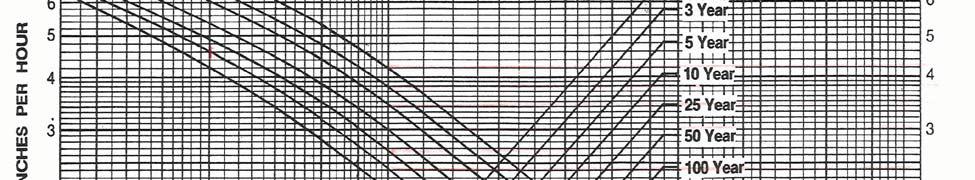
14 Figure 4 Typical Rainfall Intensity-Duration-Frequency-Curve Copyright 2010 David F. Carter 14 of 20
15 compliance with a minimum grate or inlet elevation, such as the 25-year high water elevation in the receiving water body. Elevation of Hydraulic Gradient (H.G.)-Upper This is the elevation, under design conditions, to which water will rise in the various inlets and manholes. The elevation of the H.G. should be compared to the manhole or inlet top elevation to ensure that flow remains inside the designed structure and that any required freeboard is available during conditions of peak flow. Elevation of Hydraulic Gradient (H.G.)-Lower This is the elevation of the hydraulic gradient at the downstream end of the pipe section. Crown Elevation-Upper This is the inside top of the pipe elevation at the upstream end of the section under consideration. Normal convention is to give this number to even tenths of a foot for 18-inch pipes and larger, and to even five one-hundredths of a foot for 15-inch pipes. Crown Elevation-Lower This is the inside top of the pipe elevation at the downstream end of the section under consideration. The same convention mentioned above applies. Flow Line-Upper The invert elevation of the upstream end of the pipe is shown here. Flow Line-Lower The invert elevation of the downstream end of the pipe is shown here. Copyright 2010 David F. Carter 15 of 20
16 Fall (feet) This is the hydraulic gradient fall given to the nearest one-hundredth of a foot. It does not include minor losses as does the difference between upper and lower hydraulic gradient. Fall (feet) The total physical fall of the pipe section is given to the closest one-tenth of a foot. Diameter (inches) The diameter of the culvert is given in inches. If the culvert is elliptical, the rounded equivalent is used. If it is a box culvert, the width and height are given in feet. An abbreviated description of the pipe is shown below the diameter. For instance, RCP means reinforced concrete pipe; HDPE means high density polyethylene pipe. Note: When transitioning from a smaller upstream pipe to a larger downstream pipe, the most hydraulically efficient practice is to match crown elevations. Note: Local design criteria usually dictates minimum pipe size for certain applications, such as under roadways. Although HDPE is a good substitute for RCP in certain applications, local design criteria may limit the maximum size for certain applications, such as under roadways. HDPE is much lighter than RCP and easier and cheaper to install, but does not stand up to loading stress as well as RCP. Some of the newer material, such as Hardy pipe, may also be good for certain applications. Local design criteria should always be consulted before specifying these materials. Slope (%) The slope of the hydraulic gradient is shown over the physical slope of the pipe. The minimum physical slope insuring minimum flow velocity depends on the Manning s coefficient which is dependent on the pipe material and diameter. The hydraulic gradient is calculated as: S = [Q/((1.49/n) x A x 2/3 R )] 2 Copyright 2010 David F. Carter 16 of 20
17 Some typical values of Manning s n for various materials appear in Table 5- Manning s n Values for Various Pipe Materials. Velocity (fps) The velocity resulting from the slope of the hydraulic gradient is given over the velocity resulting from the physical slope of the pipe. Velocities less than 2.5 fps should be avoided as this will result in deposition and buildup of sediment inside the pipe, which will impede flow. Likewise, high velocities in excess of 7.5 fps will enhance erosion and should also be avoided. Velocity is determined by the relationship V = Q/A. Capacity (cfs) The capacity of the culvert on the slope of the hydraulic gradient is given over the capacity of the culvert on the physical slope. Minor Loss (feet) Table 5 Manning's 'n' Values for Various Pipe Material Surface Manning's 'n' Concrete High Density Polyethylene (HDPE) Polyvinyl Chloride (PVC) Uncoated cast iron Ductile iron Corrugated Metal Pipe (CMP) Wrought-iron, black Wrought-iron, galvanized Vitrified clay This is calculated by multiplying the velocity head (v 2 /2g) by the loss coefficient (K) to determine the loss due to the configuration of the system. Loss Coefficient This is the coefficient used to determine the minor loss described above. Refer to Figure 5-Head Loss Coefficients for Estimating Energy Losses Through Manholes/Junctions for these coefficients which are based on system configuration. Cover (feet) This is the difference between the Manhole or Inlet Top Elevation (ft) and the Crown Elevation-Upper. It does not consider the thickness of the pipe. Minimum cover is Copyright 2010 David F. Carter 17 of 20
18 Figure 5 Head Loss Coefficients for Estimating Energy Losses through Manholes/Junctions Copyright 2010 David F. Carter 18 of 20
19 usually dictated by the local permitting authority, but in no case should be less then one foot. Spreadsheet Storm sewer tabulations are easily done with a computer spreadsheet program such as Excel. A lookup table can be used interactively to import pipe data for the various calculations. An example of such a table can be seen in Table 6-Lookup Table for Spreadsheet Calculations. The flow rates shown here have not yet had the slope factor applied to them. This operation occurs after they are imported by the storm sewer tabulation spreadsheet Concerning the storm sewer tabulation spreadsheet (Table 1), the only parameter that needs to be adjusted for geographic location is the rainfall intensity-duration-frequency. This is because the intensity parameter used in the spreadsheet is the intensity in inches per hour for the design frequency storm of duration equal to the time of concentration for the watershed in question. This data can be either taken from the appropriate IDF curve or calculated by equation which can be entered into the spreadsheet program. Copyright 2010 David F. Carter 19 of 20
20 Table 6 Lookup Table for Spreadsheet Calculations D A R *Flow Rates(cfs) for Various Manning's n Values DIAM AREA HYDRAULIC RADIUS PVC RCP RCP(>36") RCP(>54") HDPE (INCHES) (SQ FT) (FEET) , , , , , , , , , , , , , , , , , , , , , , , , , , , , , ,588.0 EQUIV , , , , , X X X X X X X , , X , , , , , X , , , , , X , , , , , X , , , , , X , , , , ,755.0 * The flow rates shown here have not yet had the slope factor applied to them. This operation occurs after they are imported by the storm sewer tabulation spreadsheet. Copyright 2010 David F. Carter 20 of 20
APPENDIX G HYDRAULIC GRADE LINE
 Storm Drainage 13-G-1 APPENDIX G HYDRAULIC GRADE LINE 1.0 Introduction The hydraulic grade line is used to aid the designer in determining the acceptability of a proposed or evaluation of an existing storm
PART 3 - STANDARDS FOR SEWERAGE FACILITIES DESIGN OF STORM SEWERS
 PART 3 - STANDARDS FOR SEWERAGE FACILITIES 3.3 - DESIGN OF STORM SEWERS 3.301 Design of Storm Sewers A. General Information B. Investigations and Surveys C. Special Projects 3.302 Design Criteria for Storm
CHECKLIST FOR STREETS, INLETS, AND STORM SEWER DESIGN
 CHECKLIST FOR STREETS, INLETS, I. STREET CLASSIFICATION AND DESIGN CRITERIA A. Determine drainage classification for the roadway section using Table 7-1 or Table 7-2. B. Determine the allowable flow depth
SECTION STORM DRAINAGE DESIGN, GRADING, AND WATER QUALITY TECHNICAL CRITERIA TABLE OF CONTENTS PAGE 402 STORM DRAINAGE DESIGN CRITERIA 400-1
 CITY OF THORNTON Standards and Specifications Revised: October 2012 SECTION 400 - STORM DRAINAGE DESIGN, GRADING, AND WATER QUALITY TECHNICAL CRITERIA TABLE OF CONTENTS PAGE 401 GENERAL PROVISIONS 400-1
10.0 Storm Sewer Systems
 October 2003 Chapter 10.0, Storm Sewer Systems Page 1 10.0 Storm Sewer Systems 10.1 Introduction A storm sewer system consists of a system of inlets, pipes, manholes, junctions, cleanouts, outlets, and
Stormwater Local Design Manual For Houston County, Georgia
 Stormwater Local Design Manual For Houston County, Georgia Adopted November 15, 2005 TABLE OF CONTENTS 1. FORWARD... 1 2. GENERAL LEVEL OF SERVICE STANDARDS... 2 2.1. DETENTION REQUIREMENTS... 2 2.1.1.
Appendix I OFFICE OF THE MORGAN COUNTY SURVEYOR STORMWATER DESIGN MANUAL 7/1/2008
 Appendix I OFFICE OF THE MORGAN COUNTY SURVEYOR This Page Left Intentionally Blank OFFICE OF THE MORGAN COUNTY SURVEYOR APPENDIX I PAGE 1 Appendix II OFFICE OF THE MORGAN COUNTY SURVEYOR This Page Left
DIVISION 5 STORM DRAINAGE CRITERIA
 DIVISION 5 STORM DRAINAGE CRITERIA Section 5.01 GENERAL The following storm drainage design criteria shall apply to all storm drainage designs in the City. Additional design criteria are specified in the
RE: Final Drainage Letter: Northwest Aurora Alley Improvements 2016
 April 12, 2016 Mr. Craig Perl, P.E. Senior Engineer City of Aurora Public Works Department 15151 E. Alameda Parkway Aurora, CO 80012 RE: Final Drainage Letter: Northwest Aurora Alley Improvements 2016
MODEL Stormwater Local Design Manual. City of Centerville
 MODEL Stormwater Local Design Manual City of Centerville Adopted December 6, 2005 TABLE OF CONTENTS 1. FORWARD... 1 2. GENERAL LEVEL OF SERVICE STANDARDS... 1 2.1. DETENTION REQUIREMENTS... 1 2.1.1. Discharge
DRAINAGE & DESIGN OF DRAINAGE SYSTEM
 Drainage on Highways DRAINAGE & DESIGN OF DRAINAGE SYSTEM P. R.D. Fernando Chartered Engineer B.Sc.(Hons), M.Eng. C.Eng., MIE(SL) Drainage Requirement of Highway Drainage System Introduction Drainage means
Highway Drainage 1- Storm Frequency and Runoff 1.1- Runoff Determination
 Highway Drainage Proper drainage is a very important consideration in design of a highway. Inadequate drainage facilities can lead to premature deterioration of the highway and the development of adverse
Chapter 11 Culverts and Bridges
 Chapter 11 Culverts and Bridges Contents 1.0 Introduction... 1 2.0 General Design... 1 2.1 Design Criteria... 1 2.2 Design Flows... 1 2.3 Permitting and Regulations... 1 2.4 Aesthetics and Safety... 2
STORM DRAINAGE DESIGN CRITERIA
 BWM Orig. 01/01/05 Revised 01/01/10 LUCAS COUNTY ENGINEERS OFFICE STORM DRAINAGE DESIGN CRITERIA Drainage The design of storm sewer systems will be based upon the Rational Method using the equation Q=CiA
Appendix J: Storm Conveyance Design Parameters
 Appendix J: Storm Conveyance Design Parameters Drain Commissioner 39 February 2005 STORM DRAINAGE DESIGN CRITERIA A. STORM SEWERS 1. The required discharge capacity shall be determined by the Rational
Jacobi, Toombs, and Lanz, Inc.
 Area 5: Blackiston Mill Road at Dead Man's Hollow Flooding Assessment Jacobi, Toombs, and Lanz, Inc. This document summarizes an assessment of drainage and flooding concerns and provides recommendations
LAWRENCE, KANSAS STORMWATER MANAGEMENT CRITERIA
 LAWRENCE, KANSAS STORMWATER MANAGEMENT CRITERIA FEBRUARY 1996 CITY OF LAWRENCE, KANSAS STORMWATER MANAGEMENT CRITERIA TABLE OF CONTENTS Pg 1.0 GENERAL 1.1 Introduction... 1 1.2 Applicability... 1 1.3 General
Hydrology Study. Ascension Heights Subdivision Ascension Drive at Bel Aire Road San Mateo, California (Unincorporated)
") Hydrology Study Ascension Heights Subdivision Ascension Drive at Bel Aire Road San Mateo, California (Unincorporated) Prepared for San Mateo Real Estate & Construction March 9, 21 Rev. 1 11-8-211 Rev.
Hydrology Study Ascension Heights Subdivision Ascension Drive at Bel Aire Road San Mateo, California (Unincorporated) Prepared for San Mateo Real Estate & Construction March 9, 21 Rev. 1 11-8-211 Rev.
INFLOW DESIGN FLOOD CONTROL SYSTEM PLAN PLANT GREENE COUNTY ASH POND ALABMA POWER COMPANY
 INFLOW DESIGN FLOOD CONTROL SYSTEM PLAN PLANT GREENE COUNTY ASH POND ALABMA POWER COMPANY Section 257.82 of EPA s regulations requires the owner or operator of an existing or new CCR surface impoundment
INFLOW DESIGN FLOOD CONTROL SYSTEM PLAN 40 C.F.R. PART PLANT YATES ASH POND B (AP-B ) GEORGIA POWER COMPANY
 GEORGIA POWER COMPANY") INFLOW DESIGN FLOOD CONTROL SYSTEM PLAN 40 C.F.R. PART 257.82 PLANT YATES ASH POND B (AP-B ) GEORGIA POWER COMPANY EPA s Disposal of Coal Combustion Residuals from Electric Utilities Final Rule (40 C.F.R.
INFLOW DESIGN FLOOD CONTROL SYSTEM PLAN 40 C.F.R. PART 257.82 PLANT YATES ASH POND B (AP-B ) GEORGIA POWER COMPANY EPA s Disposal of Coal Combustion Residuals from Electric Utilities Final Rule (40 C.F.R.
The Islamic University of Gaza- Civil Engineering Department Sanitary Engineering- ECIV 4325 L5. Storm water Management
 The Islamic University of Gaza- Civil Engineering Department Sanitary Engineering- ECIV 4325 L5. Storm water Management Husam Al-Najar Storm water management : Collection System Design principles The Objectives
INFLOW DESIGN FLOOD CONTROL SYSTEM PLAN PLANT BARRY ASH POND ALABAMA POWER COMPANY
 INFLOW DESIGN FLOOD CONTROL SYSTEM PLAN PLANT BARRY ASH POND ALABAMA POWER COMPANY Section 257.82 of EPA s regulations requires the owner or operator of an existing or new CCR surface impoundment or any
INFLOW DESIGN FLOOD CONTROL SYSTEM PLAN 40 C.F.R. PART PLANT YATES ASH POND 3 (AP-3) GEORGIA POWER COMPANY
 GEORGIA POWER COMPANY") INFLOW DESIGN FLOOD CONTROL SYSTEM PLAN 40 C.F.R. PART 257.82 PLANT YATES ASH POND 3 (AP-3) GEORGIA POWER COMPANY EPA s Disposal of Coal Combustion Residuals from Electric Utilities Final Rule (40 C.F.R.
INFLOW DESIGN FLOOD CONTROL SYSTEM PLAN 40 C.F.R. PART 257.82 PLANT YATES ASH POND 3 (AP-3) GEORGIA POWER COMPANY EPA s Disposal of Coal Combustion Residuals from Electric Utilities Final Rule (40 C.F.R.
Contact the Jurisdictional Engineer for materials allowed by each jurisdiction.
 Design Manual Chapter 3 - Sanitary Sewers 3C - Facility Design 3C-1 Facility Design A. Capacity of Pipe Pipe sizes 15 inches and smaller should carry the peak flow at a depth of no more than 0.67 of the
Facilities Development Manual
 State of Wisconsin Department of Transportation Facilities Development Manual ORIGINATOR Director, Bureau of Highway Development PROCEDURE 13-25-35 CHAPTER 13 Drainage SECTION 25 Storm Sewer Design SUBJECT
Article 20: Erosion Control and Stormwater Management
 Article 20: Erosion Control and Stormwater Management Section 360: Purpose, Scope of Authority, Performance Guarantee and Approvals A. Purpose. The purpose of this document is to set forth minimum requirements
APPENDIX C INLETS. The application and types of storm drainage inlets are presented in detail in this Appendix.
 Storm Drainage 13-C-1 APPENDIX C INLETS 1.0 Introduction The application and types of storm drainage inlets are presented in detail in this Appendix. 2.0 Inlet Locations Inlets are required at locations
iswm TM Technical Manual Hydrology:
 : 1.0 2.0 Downstream Assessment 3.0 Streambank Protection 4.0 Water Balance 5.0 Rainfall Tables 6.0 Hydrologic Soils Data Table of Contents 1.0... HO-1 1.1 Estimating Runoff... HO-1 1.1.1 Introduction
Hydrology Study. For Bella Terrazza Portion of Lot 1, Block 39, Subdivision of S Tract, Rancho El Cajon El Cajon, CA 92021
 Hydrology Study For Bella Terrazza Portion of Lot 1, Block 39, Subdivision of S Tract, Rancho El Cajon El Cajon, CA 92021 Prepared for Daryl Priest - Priest Development Corporation 124 West Main Street,
Storm Sewer Design. Bob Pitt University of Alabama and Shirley Clark Penn State Harrisburg
 Storm Sewer Design Bob Pitt University of Alabama and Shirley Clark Penn State Harrisburg Major floods are dramatic and water flow routes must be recognized when minor drainage systems fail. These types
Chapter 6. Hydrology. 6.0 Introduction. 6.1 Design Rainfall
 6.0 Introduction This chapter summarizes methodology for determining rainfall and runoff information for the design of stormwater management facilities in the City. The methodology is based on the procedures
Project Drainage Report
 Design Manual Chapter 2 - Stormwater 2A - General Information 2A-4 Project Drainage Report A. Purpose The purpose of the project drainage report is to identify and propose specific solutions to stormwater
Considerations In Estimating Tailwater Elevations
 Considerations In Estimating Tailwater Elevations by Alphonse (Al) J. Stewart, P.E., President www.suncam.com Page 1 of 39 ************************************************************************ This
SECTION 3 DRAINAGE. 3-1 General. 3-2 Drainage Ordinances and Legal Requirements
 SECTION 3 DRAINAGE 3-1 General All Drainage plans for proposed development shall be prepared by a Professional Engineer registered in Virginia, except as noted below. Further, their seal and signature
and Hydraulic Analysis 412
 Conveyance System Design and Hydraulic Analysis This chapter presents acceptable methods for the analysis and design of storm and surface water conveyance systems. Conveyance systems can be separated into
CITY OF TROY DESIGN STANDARDS AND CONSTRUCTION SPECIFICATIONS
 CITY OF TROY DESIGN STANDARDS AND CONSTRUCTION SPECIFICATIONS PREPARED BY: F-7587 JANUARY 2010 TABLE OF CONTENTS SECTION 1 SECTION 2 SECTION 3 SECTION 4 SECTION 5 SECTION 6 APPENDIX ROADWAY DESIGN DRAINAGE
Appendix G Preliminary Hydrology Study
 Appendix G Preliminary Hydrology Study Preliminary Hydrology Study VESTING TTM 72608 Long Beach, CA Prepared for: The Long Beach Project, LLC 888 San Clemente, Suite 100 New Port Beach, CA May 28, 2014
Overview of NRCS (SCS) TR-20 By Dr. R.M. Ragan
 TR-20 By Dr. R.M. Ragan") Overview of NRCS (SCS) TR-20 By Dr. R.M. Ragan TR-20 is a computer program for the simulation of runoff occurring from a single storm event. The program develops flood hydrographs from runoff and routes
Overview of NRCS (SCS) TR-20 By Dr. R.M. Ragan TR-20 is a computer program for the simulation of runoff occurring from a single storm event. The program develops flood hydrographs from runoff and routes
III. INVENTORY OF EXISTING FACILITIES
 III. INVENTORY OF EXISTING FACILITIES Within the Growth Management Boundary, the existing storm drainage facilities are largely associated with development that has historically occurred in the ten drainage
Irrigation Rehabilitation Program Design and Construction Standards
 Irrigation Rehabilitation Program Design and Construction Standards Prepared by the IRP Standards Review Committee For Alberta Agriculture and Rural Development, Irrigation Secretariat April 26, 2010 Adopted
Culvert Sizing procedures for the 100-Year Peak Flow
 CULVERT SIZING PROCEDURES FOR THE 100-YEAR PEAK FLOW 343 APPENDIX A: Culvert Sizing procedures for the 100-Year Peak Flow A. INTRODUCTION Several methods have been developed for estimating the peak flood
CHAPTER 3 STORMWATER HYDROLOGY. Table of Contents SECTION 3.1 METHODS FOR ESTIMATING STORMWATER RUNOFF
 CHAPTER 3 STORMWATER HYDROLOGY Table of Contents SECTION 3.1 METHODS FOR ESTIMATING STORMWATER RUNOFF 3.1.1 Introduction to Hydrologic Methods...3.1-1 3.1.2 Symbols and Definitions...3.1-3 3.1.3 Rainfall
Chapter 8. Inlets. 8.0 Introduction. 8.1 General
 . Introduction This chapter provides criteria and design guides for evaluating and designing storm sewer inlets in the City of Centennial. The review of all planning submittals will be based on the criteria
INFLOW DESIGN FLOOD CONTROL SYSTEM PLAN 40 C.F.R. PART PLANT BOWEN ASH POND 1 (AP-1) GEORGIA POWER COMPANY
 GEORGIA POWER COMPANY") INFLOW DESIGN FLOOD CONTROL SYSTEM PLAN 40 C.F.R. PART 257.82 PLANT BOWEN ASH POND 1 (AP-1) GEORGIA POWER COMPANY EPA s Disposal of Coal Combustion Residuals from Electric Utilities Final Rule (40 C.F.R.
INFLOW DESIGN FLOOD CONTROL SYSTEM PLAN 40 C.F.R. PART 257.82 PLANT BOWEN ASH POND 1 (AP-1) GEORGIA POWER COMPANY EPA s Disposal of Coal Combustion Residuals from Electric Utilities Final Rule (40 C.F.R.
Chapter 7. Street Drainage. 7.0 Introduction. 7.1 Function of Streets in the Drainage System. 7.2 Street Classification
 7. Introduction This chapter summarizes methods to evaluate runoff conveyance in various street cross sections and curb types in the Town of Castle Rock and identifies acceptable upper limits of street
Inflow Design Flood Control System Plan
 Inflow Design Flood Control System Plan For Compliance with the Coal Combustion Residuals Rule (40 CFR Part 257) Cherokee Station - CCR Surface Impoundments Public Service Company of Colorado Denver, Colorado
STORM AND SURFACE WATER 4-1 GENERAL...4-1
 SECTION 4 STORM AND SURFACE WATER SECTION DESCRIPTION PAGE 4-1 GENERAL...4-1 4-2 STORM DRAINAGE CONVEYANCE SYSTEM DESIGN CRITERIA...4-1 4-2.1 Overview...4-1 4-2.2 Design Flow and Route Requirements...4-2
DUKE UNIVERSITY CONSTRUCTION STANDARDS
 1 33 40 00 Storm Drainage 1. Introduction A. Duke University is divided into the main areas of the Medical Center, West Campus, Central Campus, and East Campus. The University also includes the Washington
Standards for Soil Erosion and Sediment Control in New Jersey May 2012 STANDARD FOR SLOPE PROTECTION STRUCTURES. Definition
 STANDARD FOR SLOPE PROTECTION STRUCTURES Definition Structures to safely conduct surface runoff from the top of a slope to the bottom of the slope. Purpose The purpose of this practice is to convey storm
Grass Channel STORMWATER MANAGEMENT SUITABILITY KEY CONSIDERATIONS
 4.0 Structural Stormwater Control Description: Vegetated open channels designed to filter stormwater runoff and meet velocity targets for the water quality design storm and the Streambank Protection storm
Catch Basin Inserts: Method to Determine CB Inserts Act as Full Capture Devices
 WATERSHED PROTECTION DIVISION DEPARTMENT OF PUBLIC WORKS BUREAU OF SANITATION CITY OF LOS ANGELES Catch Basin Inserts: Method to Determine CB Inserts Act as Full Capture Devices Catch Basin Inserts: Method
Summary of Detention Pond Calculation Canyon Estates American Canyon, California
 July 15, 2015 Bellecci & Associates, Inc Summary of Detention Pond Calculation Canyon Estates American Canyon, California 1. Methodology: Method: Unit Hydrograph Software: Bentley Pond Pack Version 8i
Plan Name Plan No. Submitting Firm Contact Engineer. Review Date ESI Team ENGINEERS AND SURVEYORS INSTITUTE PEER REVIEW CHECKLIST CITY OF ALEXANDRIA
 EROSION AND SEDIMENT CONTROL CHECKLIST (E&S) VIRGINIA EROSION AND SEDIMENT CONTROL HANDBOOK (1 of 2) Item # Description OK NO N/A 1 Limits of clearing and grading match on all appropriate sheets 2 Construction
ARTICLE V: STORMWATER MANAGEMENT AND DRAINAGE SYSTEMS
 ARTICLE V: STORMWATER MANAGEMENT AND DRAINAGE SYSTEMS Section 501: Purpose An adequate drainage system including necessary ditches, pipes, culverts, drains, inlets, bridges, detention ponds, etc. shall
APPENDIX IV. APPROVED METHODS FOR QUANTIFYING HYDROLOGIC CONDITIONS OF CONCERN (NORTH ORANGE COUNTY)
") APPENDIX IV. APPROVED METHODS FOR QUANTIFYING HYDROLOGIC CONDITIONS OF CONCERN (NORTH ORANGE COUNTY) Hydromodification design criteria for the North Orange County permit area are based on the 2- yr, 24-hr
APPENDIX IV. APPROVED METHODS FOR QUANTIFYING HYDROLOGIC CONDITIONS OF CONCERN (NORTH ORANGE COUNTY) Hydromodification design criteria for the North Orange County permit area are based on the 2- yr, 24-hr
Location Drainage Study
 Location Drainage Study PROJECT ROUTE: LIMITS: MUNICIPALITY/COUNTY: JOB NUMBER: IL 47 at Burlington Road 750ft NW to 750ft SE of IL 47(Burlington), & 1000ft S to 1000ft N of Burlington (IL47) Kane County
Section 600 Runoff Table of Contents
 Section 600 Runoff Table of Contents 601 INTRODUCTION...600-1 602 RATIONAL METHOD...600-1 602.1 Rational Method Formula...600-2 602.2 Time of Concentration...600-2 602.3 Intensity...600-4 602.4 Runoff
Preliminary Drainage Analysis
 Preliminary Drainage Analysis Tanimura and Antle Employee Housing Town of Spreckels County of Monterey, California LIB150205 May 29, 2015 Prepared For: Tanimura and Antle Produce Prepared By: 9699 Blue
DESIGN STANDARDS SECTION DS 4 STORM DRAIN
 DS 4-01 GENERAL: DESIGN STANDARDS SECTION DS 4 STORM DRAIN A. INTENT: The intent of these Design Standards is to provide minimum standards for the design of a storm drain system that will collect storm
Table of Contents. Overview... 1
 Chapter 3 Chapter 3 Table of Contents Overview... 1 Rainfall... 2 3-2-1 Rainfall Depths and Intensities... 2 3-2-2 Design Storm Distribution for Colorado Urban Hydrograph Procedure (CUHP)... 5 3-2-3 Temporal
CACHE VALLEY STORM WATER DESIGN STANDARDS. As Amended by Logan City November 2010
 CACHE VALLEY STORM WATER DESIGN STANDARDS As Amended by Logan City November 2010 Updated November 2010 Table of Contents A. Definitions... 3 B. Design Requirements... 5 1. Storm Event... 5 2. Allowable
City of Oakland. Public Works Agency Standards STORM DRAINAGE DESIGN GUIDELINES. Engineering Design & ROW Management Division
 City of Oakland PUBLIC WORKS AGENCY 250 FRANK H. OGAWA PLAZA 4 TH FLOOR OAKLAND, CALIFORNIA 94612 (510) 238-3437 FAX (510) 238-7227 TTD (510) 238-3254 Public Works Agency Standards STORM DRAINAGE DESIGN
Hancor, Inc. Drainage Handbook Hydraulics 3-1
 Hancor, Inc. Drainage Handbook Hydraulics 3-1 3-0 HYDRAULICS TABLE OF CONTENTS 3-1 Overview of Hydraulic Considerations...3-2 3-2 Design Manning s Value...3-2 3-3 Discharge Curves...3-4 3-3 The Conveyance
3.0 STORM DRAINAGE SYSTEM DESIGN
 SPALDING COUNTY, GEORGIA CHAPTER 3 3.0 STORM DRAINAGE SYSTEM DESIGN... 3-1 3.1 OVERVIEW... 3-1 3.1.1 INTRODUCTION... 3-1 3.1.2 DRAINAGE SYSTEM COMPONENTS... 3-1 3.1.3 INLET AND STORM DRAIN PIPE DESIGN...
CITY OF ROLLA STORMWATER DESIGN STANDARDS
 Revised Nov 07, 2017 4:28 p.m. CITY OF ROLLA STORMWATER DESIGN STANDARDS Prepared by: NTEGRITY Engineering, Inc. 1714 East 10 th Street P.O. Box 700 Rolla, MO 65402-0700 Phone: (573) 341-2100 Fax: (573)
Learning objectives. Upon successful completion of this lecture, the participants will be able to:
 Solomon Seyoum Learning objectives Upon successful completion of this lecture, the participants will be able to: Describe and perform the required step for designing sewer system networks Outline Design
PRELIMINARY DRAINAGE REPORT NEWCASTLE FIRE STATION OLD STATE HIGHWAY
 PRELIMINARY DRAINAGE REPORT FOR THE NEWCASTLE FIRE STATION OLD STATE HIGHWAY PREPARED FOR THE NEWCASTLE FIRE PROTECTION DISTRICT JULY 2014 BY ROSEVILLE DESIGN GROUP, INC. ROSEVILLE DESIGN GROUP, Inc Established
Hydrologic Study Report for Single Lot Detention Basin Analysis
 Hydrologic Study Report for Single Lot Detention Basin Analysis Prepared for: City of Vista, California August 18, 2006 Tory R. Walker, R.C.E. 45005 President W.O. 116-01 01/23/2007 Table of Contents Page
STORMWATER MANAGEMENT CRITERIA
 JOPLIN, MISSOURI STORMWATER MANAGEMENT CRITERIA AM ALLGEIER, MARTIN and ASSOCIATES, INC. Consulting Engineers and Surveyors 1.0 GENERAL 1.1 Introduction: This document provides uniform procedures
HYDROLOGIC-HYDRAULIC STUDY ISABELLA OCEAN RESIDENCES ISLA VERDE, CAROLINA, PR
 HYDROLOGIC-HYDRAULIC STUDY ISABELLA OCEAN RESIDENCES ISLA VERDE, CAROLINA, PR 1 INTRODUCTION 1.1 Project Description and Location Isabella Ocean Residences is a residential development to be constructed
CITY UTILITIES DESIGN STANDARDS MANUAL
 CITY UTILITIES DESIGN STANDARDS MANUAL () September 2017 Page Chapter 1 Acronyms and Definitions 1.01 Purpose 1 1.02 Acronyms 1 1.03 Definitions 3 Chapter 2 Introduction 2.01 Purpose 1 2.02 Applicability
Chapter H. Introduction to Surface Water Hydrology and Drainage for Engineering Purposes
 Chapter H. Introduction to Surface Water Hydrology and Drainage for Engineering Purposes As seen in Figure H.1, hydrology is a complex science that deals with the movement of water between various stages
6. Design Requirements for Storm Drainage Facilities
 6.01 General 6. Design Requirements for Storm Drainage Facilities 6.01.01 Introduction and Mission Statement The mission of these stormwater design criteria is to: Protect property and infrastructure Prevent
4.1 General Methodology and Data Base Development
 Chapter 4 METHODOLOGY 4.1 General and Data Base Development This report project utilized several computer software models and analysis techniques to create the numeric data on which decisions for this
SECTION 2 DESIGN CRITERIA
 SECTION 2 DESIGN CRITERIA 2.1 GENERAL The following criteria will be utilized by the District Engineer, and/or a consultant, in the review of development plans for recommending approval of the proposed
Activity Calculating Property Drainage
 Page 1 of 5 Activity 2.3.11 Calculating Property Drainage Introduction When a property is developed, it is important to understand that changes to watershed characteristics (i.e., land use, slope, soil
V. DRAINAGE IMPROVEMENTS
 V. DRAINAGE IMPROVEMENTS 5.1 Formulation of Drainage Improvements As indicated in Chapter 4, following the completion of the hydrologic analysis associated with future land use conditions, drainage improvements
PART I STORM DRAINAGE CRITERIA. 1.1 Statement Of Policy STORM Town Jurisdiction STORM Design Criteria & Water Quality STORM-2
 PART I STORM DRAINAGE CRITERIA SECTION 1: DRAINAGE POLICY 1.1 Statement Of Policy STORM-1 1.2 Town Jurisdiction STORM-1 1.3 Design Criteria & Water Quality STORM-2 SECTION 2: SUBMITTAL REQUIREMENTS 2.1
Treatment Volume: Curve Numbers. Composite CN or Not? Treatment Volume: Curve Numbers. Treatment Volume: Calculation. Treatment Volume: Calculation
 Stormwater Engineering Bioretention Design Bill Hunt, PE, Ph.D. Extension Specialist & Assistant Professor NCSU-BAE www.bae.ncsu.edu/stormwater Bioretention Design Six Step Process 1 Determine Volume to
FIRM NAME DESIGNER: CHECKER: DATE: FPID #: DESCRIPTION: COUNTY: DRAINAGE DESIGN CHECKLIST. Designers Initials. Checkers Initials.
 I. Drainage Report A. Executive Summary - Brief Overview of Project Drainage Design B. Project Description 1. Existing Conditions 2. Proposed Project Conditions 3. Project Justification Narrative - Basin
Stormwater Drainage Criteria Manual. City Of Clearwater Engineering Department Effective July 1, 2015
 Stormwater Drainage Criteria Manual City Of Clearwater Engineering Department Effective July 1, 2015 Engineering Department STORMWATER DRAINAGE CRITERIA MANUAL Table of Contents STORMWATER DRAINAGE CRITERIA
DESIGN BULLETIN #16/2003 (Revised July 2007) Drainage Guidelines for Highways Under Provincial Jurisdiction in Urban Areas.
 Drainage Guidelines for Highways Under Provincial Jurisdiction in Urban Areas.") Drainage Guidelines for Highways Under Provincial Jurisdiction in Urban Areas. July 2007 Update to Design Bulletin #16/2003: Added under Design Criteria Culverts of 600mm diameter are commonly used to
Drainage Guidelines for Highways Under Provincial Jurisdiction in Urban Areas. July 2007 Update to Design Bulletin #16/2003: Added under Design Criteria Culverts of 600mm diameter are commonly used to
ATTACHMENT 4: Design Calculations and Construction Details
 Pennsylvania Pipeline Project Erosion and Sediment Control Plan Southeast Region: Spread 6 November 2016 ATTACHMENT 4: Design Calculations and Construction Details Tetra Tech Pennsylvania Pipeline Project
STORMWATER RUN-ON AND RUN-OFF CONTROL PLAN ENTERGY ARKANSAS, INC. INDEPENDENCE PLANT CLASS 3N CCR LANDFILL
 STORMWATER RUN-ON AND RUN-OFF CONTROL PLAN ENTERGY ARKANSAS, INC. INDEPENDENCE PLANT CLASS 3N CCR LANDFILL PERMIT NO. 0200-S3N-R2 AFIN: 32-00042 OCTOBER 12, 2016 STORMWATER RUN-ON AND RUN-OFF CONTROL PLAN
HYDROLOGY STUDY PREPARED FOR: MARKHAM PERRIS LLC 302 WEST FIFTH STREET, SUITE 103 SAN PEDRO, CA (310) FOR THE PROJECT:
 FOR THE PROJECT:") HYDROLOGY STUDY PREPARED FOR: MARKHAM PERRIS LLC 302 WEST FIFTH STREET, SUITE 103 SAN PEDRO, CA 90731 (310) 241-2992 FOR THE PROJECT: PERRIS VALLEY COMMERCE CENTER BUILDING PERRIS, CALIFORNIA PROJECT NUMBER:
HYDROLOGY STUDY PREPARED FOR: MARKHAM PERRIS LLC 302 WEST FIFTH STREET, SUITE 103 SAN PEDRO, CA 90731 (310) 241-2992 FOR THE PROJECT: PERRIS VALLEY COMMERCE CENTER BUILDING PERRIS, CALIFORNIA PROJECT NUMBER:
Municipal Stormwater Ordinances Summary Table
 APPENDIX F Municipal Ordinances Summary Table Municipality Abington Bryn Athyn Borough Hatboro Borough Ordinance, SALDO Runoff equals pre post Erosion Sediment Control Water Quality Requirements Any which
STORM WATER MANAGEMENT REPORT
 Silvercreek Junction STORM WATER MANAGEMENT REPORT Howitt Creek at the Silvercreek Parkway Site Guelph, Ontario August, 2008 TSH File 22304A-04 August 19, 2008 STORMWATER MANAGEMENT REPORT Howitt Creek
4.1 Browns Canal Introduction Sub-basin Information
 Section 4 Withlacoochee Basin 4.1 Browns Canal 4.1.1 Introduction The information presented in this sub-basin plan for Browns Canal is intended to provide the reader with information necessary to understand
City Plaza Residential (TPM ) Preliminary Hydrology Report
 Preliminary Hydrology Report") Hydrology Study City Plaza Residential (TPM 2016-127) Preliminary Hydrology Report Orange, Orange County, California Prepared For: Greenlaw Partners 18301 Von Karman Avenue, Suite 250 Irvine, CA 92612
Hydrology Study City Plaza Residential (TPM 2016-127) Preliminary Hydrology Report Orange, Orange County, California Prepared For: Greenlaw Partners 18301 Von Karman Avenue, Suite 250 Irvine, CA 92612
City of Saint John. Storm Drainage Design Criteria Manual
 Storm Drainage Design Criteria Manual March 7, 2016 LIST OF 2016 REVISIONS PAGES SECTION TITLE iii, iv, v, vi All Table of Contents 31-35 3 SUBMISSION REQUIREMENTS March 7, 2016 Page i DISCLAIMER The material
3.0 DESIGN CRITERIA FOR SANITARY SEWER FACILITIES
 3.0 DESIGN CRITERIA FOR SANITARY SEWER FACILITIES All sanitary sewers shall be designed in accordance with these Design Standards, LBWD Rules and Regulations, and to accepted engineering principles. In
CHAPTER 200 STORM SEWER CONSTRUCTION STANDARDS
 CHAPTER 200 STORM SEWER CONSTRUCTION STANDARDS Storm Sewer System: 1. Detention/retention of stormwater runoff shall be provided in accordance with the requirements of the DuPage County Countywide Stormwater
GRASS-LINED CHANNEL (acre) CODE 840
 CODE 840") NATURAL RESOURCES CONSERVATION SERVICE ILLINOIS URBAN MANUAL PRACTICE STANDARD GRASS-LINED CHANNEL (acre) CODE 840 (Source: NC Erosion and Sediment Control Field Manual) DEFINITION A natural or constructed
NATURAL RESOURCES CONSERVATION SERVICE ILLINOIS URBAN MANUAL PRACTICE STANDARD GRASS-LINED CHANNEL (acre) CODE 840 (Source: NC Erosion and Sediment Control Field Manual) DEFINITION A natural or constructed
FINAL DRAINAGE REPORT FOR: LOT 1 BLOCK 1 ROLLINS SUBDIVISION FILING #5. Prepared for:
 215063FD1 2014-3046 01J FINAL DRAINAGE REPORT FOR: LOT 1 BLOCK 1 ROLLINS SUBDIVISION FILING #5 Prepared for: Mr. Hari Sach RV America 3640 N. Chambers Road Aurora, Co. 80011 Phone: 303-360-0252 Email:
CRITERIA FOR STORMWATER DESIGN
 ..CHAPTER.. CRITERIA FOR STORMWATER DESIGN 2.1 Integrated Site Design Approach 2.1.1 Introduction This chapter represents the requirements, policies and other guidance for stormwater management design
HYDROLOGIC CONSIDERATIONS. 22 nd Annual Nonpoint Source Pollution Conference Saratoga Springs, NY
 LOW IMPACT DEVELOPMENT HYDROLOGIC CONSIDERATIONS 22 nd Annual Nonpoint Source Pollution Conference Saratoga Springs, NY May 18, 2011 PRESENTATION AGENDA Introduction Definitions Discuss Impacts to Hydrologic
Chapter 4. Drainage Report and Construction Drawing Submittal Requirements
 4.0 Introduction The requirements presented in this section shall be used to aid the design engineer or applicant in the preparation of drainage reports, drainage studies, and construction drawings for
CITY UTILITIES DESIGN STANDARDS MANUAL
 CITY UTILITIES DESIGN STANDARDS MANUAL Book 2 (SW) SW1 September 2017 SW1.01 Purpose SW1.02 Acronyms ANSI ASTM BFE BMP CERCLA CFS CMP CN CSI CUE DIP DPS DVS EGL FEMA FFE FHWA FPG GI GIS GISSD GPS HEC-RAS
COON CREEK WATERSHED DISTRICT PERMIT REVIEW. Spring Lake Park Schools Westwood Middle School st Avenue NE, Spring Lake Park, MN 55432
 PAN 16-112, Westwood Middle School, Page 1 of 6 COON CREEK WATERSHED DISTRICT PERMIT REVIEW MEETING DATE: August 22, 2016 AGENDA NUMBER: 10 FILE NUMBER: 16-112 ITEM: Westwood Middle School RECOMMENDATION:
HYDROLOGY STUDY LA MIRADA BOULEVARD La Mirada, California
 HYDROLOGY STUDY 12000 LA MIRADA BOULEVARD La Mirada, California TTM 73119 Prepared for: The Olson Company 3010 Old Ranch Parkway, Suite 100 Seal Beach, CA 90740 Contact: Mr. Aaron Orenstein (562) 370-9531