Stormwater Treatment Measure Sizing and Design Considerations SMCWPPP C.3 Workshop June 21, 2017
|
|
|
- Evan Melton
- 5 years ago
- Views:
Transcription
1 Stormwater Treatment Measure Sizing and Design Considerations SMCWPPP C.3 Workshop June 21, 2017 Jill Bicknell, P.E., EOA, Inc.
2 Presentation Overview Sizing/Design of Self Treating and Self Retaining Areas Sizing/Design of Treatment Measures Determining the Water Quality Design Flow and Volume Bioretention and Flow Through Planters Pervious Pavement and Infiltration Trenches High Rate Media Filters


3 Site Design Measures to Reduce Runoff Requiring Treatment Self Treating Areas Interceptor Tree Credits Self Retaining Areas
4 Self-Treating Area Pervious area that treats rain falling on itself only, via ponding, infiltration and ET Landscaping Green roof Pervious pavement Artificial turf Landscaped areas must retain approx. 1 of rain Pervious pavement and artificial turf must be designed to store and infiltrate the C.3.d amount of runoff in order to qualify as self treating areas
 Runoff from impervious areas can flow to a smaller treatment")
5 Self-Treating Areas Reduce the Area Requiring Treatment Runoff from pervious portions of the project (after infiltrating 1 ) can flow directly to the storm drain (if not mixing with runoff from impervious areas) Runoff from impervious areas can flow to a smaller treatment measure
6 Interceptor Tree Credits Self treating area credit allowed based on the interception of rainwater by the tree canopy Intended for small areas that can t be treated Type of Tree Planted or Preserved Evergreen: new planting Deciduous: new planting Preserve existing trees (either evergreen or deciduous) Square footage deducted from area requiring stormwater treatment 200 sq. ft. per tree 100 sq. ft. per tree Square footage beneath canopy
 No special soils required Area must be able to retain up to 3 of")
7 Self-Retaining Area Pervious area that retains first 1 of rainfall on itself and runoff from adjacent impervious area, up to a 2:1 ratio (impervious:pervious) Roof runoff dispersion to depressed landscaped area Partial green roofs Pervious pavement (with adequate storage) No special soils required Area must be able to retain up to 3 of ponding
8 Design of Self-Retaining Areas Landscaped areas Plan sheet should indicate a relatively flat, concave, landscaped surface with ponding depth as follows: Depth = 1 inch + [(Imperv Area Perv Area) X 1 inch] Elevation of any area drains should be set at top of ponding depth Partial green roofs and pervious pavement Calculate depth of water quality volume using equation above Determine depth of media/aggregate require to store the water quality volume

9 Self-Retaining Areas Reduce the Area that Requires Treatment Runoff from impervious portions of the project can flow directly to a pervious area that is at least 50% of the size of the contributing area Runoff from other impervious areas can flow to a smaller treatment measure
10 C.3.d Sizing Criteria for Treatment Measures Volume based sizing criteria: URQM Method use formula and volume capture coefficients in Urban Runoff Quality Management, WEF/ASCE MOP No. 23 (1998), pages CASQA BMP Handbook Method Determine volume equal to 80% of the annual runoff, using methodology in Appendix D of the CASQA BMP Handbook (2003) using local rainfall data Additional sizing information was developed for San Mateo County rain gages (see C.3 Technical Guidance Appendix C)

11 Treatment Measure Design Criteria Regions for San Mateo County Figure 1 in Appendix 3 of the C.3 Technical Guidance
12 C.3.d Sizing Criteria Flow based sizing criteria: Factored Flood Flow 10% of the 50 year peak flow rate, determined using Intensity Duration Frequency curves from local flood control agency Not generally used Percentile Rainfall Intensity Flow of runoff produced by a rain event equal to two times the 85th percentile hourly rainfall intensity No local data available for San Mateo County Uniform Intensity Flow of runoff resulting from a rain event equal to 0.2 inches per hour intensity
13 C.3.d Sizing Criteria Flow based sizing criteria: Simplified Sizing Approach Variation of Uniform Intensity Method (0.2 in/hr) Surface area of biotreatment measure is sized to be 4% of the contributing impervious area Based on a runoff inflow of 0.2 in/hr (assume equal to the rainfall intensity), with an infiltration rate through the biotreatment soil of 5 in/hr (0.2 in/hr 5 in/hr = 0.04) Conservative approach because does not account for surface ponding; but maximizes infiltration
14 C.3.d Sizing Criteria Combination Flow & Volume Design Basis: Treatment systems can be sized to treat at least 80% of total runoff over the life of the project Option 1: Use a continuous simulation hydrologic model (typically not done for treatment measures) Option 2: Show how treatment measure sizing meets both flow and volume based criteria Used for bioretention and flow through planters See guidance in Chapter 5, Section 5.1 of C.3 Technical Guidance and Combination Flow Volume Sizing Worksheet
15 Flow- or Volume-Based Sizing for Treatment Measures? Table 5-1 Flow and Volume Based Treatment Measure Sizing Criteria Type of Treatment Measure LID? Hydraulic Sizing Criteria Bioretention area Yes Flow- or volume-based or combination Flow-through planter box Yes Flow- or volume-based or combination Tree well filter Some Flow-based Pervious pavement Yes Volume-based Infiltration trench Yes Volume-based Subsurface infiltration system Yes Volume-based Rainwater harvesting/use Yes Volume-based Media filter No Flow-based
16 Sizing Guidance Appendix B of C.3 Technical Guidance Sizing examples Appendix C of C.3 Technical Guidance Figure 1: Treatment Measure Design Criteria Regions for San Mateo County Figure 2: Mean Annual Precipitation Website: Sizing worksheets for determining water quality design volume, and combination flow/volume


17 Mean Annual Precipitation (inches) Figure 2 in Appendix C of the C.3 Technical Guidance
18 Sizing Example (Volume-based) Parking lot in Brisbane Area = 35,000 sq. ft. (0.80 acres) 100% impervious Mean annual precipitation (MAP) = 23 Rainfall Region #5, MAP = 21 35,000 sq. ft. Use the sizing worksheets to determine the water quality design volume (V WQ) Answer: V WQ = 2,332 cu. ft.
19 Sizing Bioretention Facilities Simplified Sizing (Flow Based) Approach Surface area is 4% of contributing impervious area Does not consider storage in surface ponding area Volume Based Approach Store V WQ in just surface ponding area Store V WQ in ponding area, soil media & drain rock Combination Flow and Volume Approach Compute both Q WQ and V WQ Route through facility, allowing ponding
20 Simplified Sizing Example Parking lot in Brisbane Area = 35,000 sq. ft. (0.80 acres) 100% impervious MAP not needed Uniform intensity = 0.2 in/hr Surface area of bioretention: 35,000 sq. ft. Area X 0.04 = 1,400 sq. ft. Note: if drainage area contains pervious area, multiply pervious area by 0.1 and add to impervious area to get effective impervious area
21 Sizing Bioretention Facilities: Volume-Based Approach V 1 V 2 V 3
22 Sizing Bioretention Facilities: Volume-Based Approach Method 1: Store entire volume in surface ponding area V 1 Depth (ft) Porosity Volume per sq. ft. (cubic feet) Surface Area = V WQ (cu.ft.) 0.5 cu.ft./sq.ft. Sizing Example: 2,332 cu.ft. 0.5 cu.ft./sq.ft. = 4,664 sq.ft.
23 Sizing Bioretention Facilities: Volume-Based Approach Method 2: Store volume in ponding area and media V 1 V 2 V 3 Depth (ft) Porosity Volume per sq. ft. (cubic feet) * Total 1.15 *Depth below underdrain at 6 above bottom Surface Area = V WQ (cu.ft.) 1.15 cu.ft./sq.ft. 2,332 cu.ft cu.ft./sq.ft. = 2,028 sq.ft.
24 Sizing Bioretention Facilities: Flow & Volume Approach Hydrograph Approach Runoff is routed through the treatment measure Assume rectangular hydrograph that meets both flow and volume criteria
25 Sizing Bioretention Facilities: Flow & Volume Approach 5 in/hr Determine VWQ Assume constant rainfall intensity of 0.2 in/hr continues throughout the storm (rectangular hydrograph) Calculate the duration of the storm by dividing the Unit Basin Storage by the rainfall intensity Calculate the volume of runoff that filters through the biotreatment soil at 5 in/hr over the storm duration Calculate the volume that remains on the surface and ponding depth
26 Sizing Bioretention Facilities: Flow & Volume Approach 5 in/hr To start the calculation, you have to assume a surface area A S use 3% of the contributing impervious area as a first guess Determine volume of treated water V T during storm: V T = A S x 5 in/hr x duration (hrs) x 1 in/12 ft Determine volume remaining on the surface V S : V S = V WQ V T Determine depth D of ponding on the surface: D = V S A S Repeat until depth is approximately 6 inches
27 Sizing Example (Combo Method) Parking lot in Brisbane Area = 35,000 sq. ft. (0.80 ac.) 100% impervious V WQ = 2,332 cu. ft. Adj. UBS Volume = 0.80 in. 35,000 sq. ft. Use the combination flow and volume sizing worksheet to determine the bioretention surface area Answer: 1,075 sq. ft. (with depth = 6.0 )
28 Sizing Bioretention Facilities: Comparison of Methods Example: 35,000 sq. ft. parking lot in Brisbane MAP= 23 inches, 100% impervious V BMP = 2,332 cu. ft. (80% of annual runoff) Sizing Method Surface Area (sq. ft.) Simplified Method (flow-based) 1,400 Volume ponded on surface 4,664 Volume stored in unit (V 1 +V 2 +V 3 ) 2,028 Combination flow & volume 1,075

29 Sizing Pervious Pavement and General Principles Infiltration Trenches Store the V WQ in void space of stone base/subbase and infiltrate into subgrade Surface allows water to infiltrate at a high rate Any underdrains must be placed above the void space needed to store and infiltrate the V WQ
30 Sizing Pervious Pavement and Infiltration Trenches Pervious Pavement May be self treating area or self retaining area (accept runoff from other areas) Can only be considered a pervious area if stone base/subbase sized to store the V WQ Can work where native soils have low infiltration rates (stored water depths are relatively small) Surface area is usually predetermined Base and subbase thickness usually determined by expected traffic load and saturated soil strength Slope should be 3% (or use check dams/trenches in subbase)

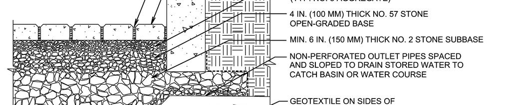
31 Pervious Pavement Typical Section Pavement surface Bedding No. 8 stone 4 in. Base No. 57 stone Thickness varies Subbase No. 2 stone Base and subbase layers available for water storage Both typically have 40% void space
32 Pervious Pavement Approach to Sizing Pervious Pavement Self Treating Check the depth of the V WQ in base/subbase: UBSV (in.) 0.40 = Depth (in.) Example: UBSV = 1.0 in., depth = 2.5 in. (Minimum depth for vehicular traffic is 10 in.) Check the time required for stored water to drain: UBSV (in.) Infiltration rate (in/hr) = Drain time (hrs) (recommend < 48 hrs)
33 Pervious Pavement Approach to Sizing Pervious Pavement Self Retaining (receives runoff from adjacent areas) Add the V WQ for adjacent areas to the V WQ for the pervious pavement, divide the total by pervious pavement area Do not exceed 2:1 ratio of contributing area to pervious area Check depth of total V WQ in base/subbase: V WQ (in.) 0.40 = Depth (in.) Example: V WQ = 3.0 in., depth = 7.5 in. Check the time required for stored water to drain: V WQ (in.) Infiltration rate (in/hr) = Drain time (hrs)


34 Underdrains: New Approach Underdrain placed in trench at bottom of section with raised outlet to allow water storage in aggregate reservoir Raised outlet

35 Underdrain: Upturned Elbow

36 Underdrain: Connection to Catch Basin/Utility Structure
37 Infiltration Trench Sizing Differences from Pervious Pavement More runoff must infiltrate in a smaller footprint Infiltration rate of site soils must be at least 0.5 in/hr (i.e., not suitable for C or D soils) Trench depths are typically between 3 and 8 feet Infiltration trench is an infiltration device Minimum 10 foot separation from seasonal high groundwater level Must meet other MRP requirements Cannot be deeper than wide (definition of Class V injection well)
38 Infiltration Trench Sizing Design Parameters Trench depth is calculated based on the soil infiltration rate, aggregate void space, and the trench storage time The stone aggregate used in the trench is typically 1.5 to 2.5 inches in diameter, which provides a void space of approximately 35 % Trenches should drain within 72 hours Place underdrain above void space needed for storage of V WQ
39 Infiltration Trench Sizing Approach to Sizing Infiltration Trenches Trench unit storage volume: S = n d n = gravel porosity (0.35); d = gravel depth (ft) Subsoil unit infiltration capacity: S i = k t 12 k = subsoil permeability (in/hr); t = time (hrs) (recommend maximum of 72 hrs) Check for trench drainage by infiltration: If S S i : Increase depth of media until S = S i to match trench capacity to infiltration capacity (may decrease surface area needed) If S > S i : Decrease depth of media until S = S i (surface area may increase)
40 Infiltration Trench Sizing Approach to Sizing Infiltration Trenches Determine required trench area: A T = V WQ S A T = Trench area required to store treatment volume (sq.ft.) V WQ = Water quality design volume (cu. ft.) S = Trench unit storage volume (cu.ft./sq.ft.) Determine required trench width: W = A T L W = Width of trench (ft.) A T = Required trench area (sq. ft.) L = Length of trench (ft.) (normally length of treatment area)
 *General Use Level Designation (GULD) for Basic Treatment")
41 Sizing High-Rate Media Filters Media Filters (cartridge type) Flow based Treatment Measure Determine Q WQ Select a product that is certified by Washington State TAPE program* Determine the TAPE approved design flow rate per cartridge Divide Q WQ by the cartridge flow rate to calculate the required number of cartridges (round up) *General Use Level Designation (GULD) for Basic Treatment
 A tree box filter that uses biotreatment soil media can be sized like a flow")
42 Sizing High-Rate Media Filters Proprietary Tree Box Filters Flow based Treatment Measure Determine Q WQ Select a product that is certified by Washington State TAPE program Determine the TAPE approved infiltration rate for the media Calculate the required surface area by dividing Q WQ by the infiltration rate (ft/sec) A tree box filter that uses biotreatment soil media can be sized like a flow through planter
43 Sizing Example (Flow-based) Rooftop in Brisbane (Special Project) 35,000 sq. ft. Area = 35,000 sq. ft. (0.80 ac.) 100% impervious Uniform intensity = 0.2 in/hr Runoff coefficient = 0.90 Use the Rational Method (Q = CIA) determine the water quality design flow, Q WQ Answer: Q WQ = (0.9)(0.2)(0.8) = cfs

44 Sizing Example (Flow-based) Rooftop in Brisbane (Special Project) Q WQ = cfs = 64.6 gpm Select media filter type Check for TAPE certification and allowable flow rate 35,000 sq. ft. Example: FloGard Perk Filter Size at hydraulic loading rate of 1.5 gpm/ft 2 of media surface area For 18 cartridge, loading rate is 10.2 gpm/cartridge 64.6 gpm 10.2 gpm/cartridge = 6.3, or 7 cartridges

45 Questions? Jill Bicknell, P.E , X 1 jcbicknell@eoainc.com
Sizing Calculations and Design Considerations for LID Treatment Measures
 SCVURPPP C.3 Workshop December 18, 2012 Sizing Calculations and Design Considerations for LID Treatment Measures Jill Bicknell, P.E., EOA, Inc. Santa Clara Valley Urban Runoff Pollution Prevention Program
June 2017 C.3 Workshop Sizing Example. Section II.B Sizing Volume-Based Treatment Measures based on the Adapted CASQA Stormwater BMP Handbook Approach
 SANTA CLARA VALLEY URBAN RUNOFF POLLUTION PREVENTION PROGRAM June 2017 C.3 Workshop Sizing Example Section II. Sizing for Volume-Based Treatment Measures Section II.B Sizing Volume-Based Treatment Measures
Sizing Criteria Worksheets and Examples
 Appendix B Sizing Criteria Worksheets and Examples This Appendix provides sizing criteria worksheets and examples to illustrate the correct procedures for determining the water quality design flow and
Determining the Feasibility/Infeasibility of Infiltration, Evapotranspiration and Rainwater Harvest and Use
 Determining the Feasibility/Infeasibility of Infiltration, Evapotranspiration and Rainwater Harvest and Use Jill C. Bicknell, P.E., EOA, Inc. Assistant Program Manager Santa Clara Valley Urban Runoff Pollution
Water Resources Management Plan
 B u r n s v i l l e M i n n e s o t a Water Resources Management Plan - Volume Control / Infiltration Worksheet This Appendix contains a worksheet and related information that can be used for evaluating
Evaluating the Feasibility of Infiltration and Rainwater Harvesting and Use
 Evaluating the Feasibility of Infiltration and Rainwater Harvesting and Use Presented by Laura Prickett, EOA, Inc. Prepared by Jill Bicknell, EOA, Inc. Santa Clara Valley Urban Runoff Pollution Prevention
Permeable Pavement Hydrologic Modeling
 Permeable Pavement Hydrologic Modeling Robin Kirschbaum, PE, LEED AP Alice Lancaster, PE April 24, 2013 Presentation Overview Overview of Hydrologic Modeling Performance Standards Modeling Guidelines,
Infiltration Guidelines
 Appendix E Infiltration Guidelines As a stormwater management method, infiltration means retaining or detaining water within soils to reduce runoff. Infiltration can be a cost-effective method to manage
Porous Pavement Flow Paths
 POROUS PAVEMENT MODELING Clear Creek Solutions, Inc., 2010 Porous pavement includes porous asphalt or concrete and grid/lattice systems (nonconcrete) and paving blocks. The use of any of these types of
RETENTION BASIN EXAMPLE
 -7 Given: Total Tributary Area = 7.5 ac o Tributary Area within Existing R/W = 5.8 ac o Tributary Area, Impervious, Outside of R/W = 0.0 ac o Tributary Area, Pervious, Outside of R/W = 1.7 ac o Tributary
CENTRALIZED BMPS TYPICALLY PUBLICLY OWNED & MAINTAINED BMPS, TREATING A LARGE (>20 ACRES) URBAN DRAINAGE WITH MULTIPLE LAND
 URBAN DRAINAGE WITH MULTIPLE LAND") BMP RAM BMP Type Definitions 1 CENTRALIZED BMPS TYPICALLY PUBLICLY OWNED & MAINTAINED BMPS, TREATING A LARGE (>20 ACRES) URBAN DRAINAGE WITH MULTIPLE LAND USES AND OWNERSHIP STRUCTURAL BMP TYPE OTHER NAMES
BMP RAM BMP Type Definitions 1 CENTRALIZED BMPS TYPICALLY PUBLICLY OWNED & MAINTAINED BMPS, TREATING A LARGE (>20 ACRES) URBAN DRAINAGE WITH MULTIPLE LAND USES AND OWNERSHIP STRUCTURAL BMP TYPE OTHER NAMES
Tips for Preparing/Reviewing Storm Water Control Plans (SWCP)
") Tips for Preparing/Reviewing Storm Water Control Plans (SWCP) Kristin Kerr, P.E. EOA, Inc. San Mateo Countywide Water Pollution Prevention Program June 21, 2017 Presentation Outline Important Resources
Tips for Preparing/Reviewing Storm Water Control Plans (SWCP) Kristin Kerr, P.E. EOA, Inc. San Mateo Countywide Water Pollution Prevention Program June 21, 2017 Presentation Outline Important Resources
Concurrent Session B: LID Design Specifications (Chapter 4 in Draft Manual)
") Concurrent Session B: LID Design Specifications (Chapter 4 in Draft Manual) Should vs. Must In Chapter 4, should means should, and must means must. Poorly Drained Soils Well-Drained Soils Flat Terrain
Concurrent Session B: LID Design Specifications (Chapter 4 in Draft Manual) Should vs. Must In Chapter 4, should means should, and must means must. Poorly Drained Soils Well-Drained Soils Flat Terrain
Design Example Residential Subdivision
 Design Example Residential Subdivision Rhode Island Stormwater Design and Installation Standards Manual December 2010 Public Training March 22, 2010 Richard Claytor, P.E. 508-833-6600 Appendix D: Site
Applying the Water Quality Volume
 Applying the Water Quality Volume Justin Reinhart, PE Division of Surface Water Northeast Ohio Stormwater Training Council Cleveland, Ohio & Richfield, Ohio July 12, 2018 July 25, 2018 Post-Construction
3.2 INFILTRATION TRENCH
 3.2 INFILTRATION TRENCH Type of BMP Priority Level Treatment Mechanisms Infiltration Rate Range Maximum Drainage Area LID Infiltration Priority 1 Full Retention Infiltration, Evapotranspiration (when vegetated),
Modeling Infiltration BMPs
 Modeling Infiltration BMPs CAHILL ASSOCIATES Environmental Consultants West Chester, PA (610) 696-4150 www.thcahill.com Design Goals for Calculations 1. Mitigate Peak Rates 2-Year to 100-Year 2. No Volume
Design Handbook. Low Impact Development Best Management Practices
 Design Handbook for Low Impact Development Best Management Practices Prepared by: 9/2011 Riverside County Flood Control and Water Conservation District 1995 Market Street Riverside, CA 92501 TABLE OF CONTENTS
Water Quality Management Plan
 Water Quality Management Plan For El Centro Aquatic Center Park Avenue between 4 th Street and 6 th Street August 5, 216 Prepared by Arsalan Dadkhah, Ph.D., PE (RCE 4156) D-MAX Engineering, Inc. 722 Trade
County of Los Angeles - Department of Public Works
 GENERAL PROJECT INFORMATION County of Los Angeles - Department of Public Works Building and Safety/Land Development Division LOW IMPACT DEVELOPMENT REVIEW SHEET (2017 Los Angeles County Building Code,
9220 Wightman Road, Suite 120 Montgomery Village, Maryland Phone Fax
 9220 Wightman Road, Suite 0 Montgomery Village, Maryland 20886-79 Engineers Planners Landscape Architects Surveyors Phone 301.670.0840 Fax 301.948.0693 www.mhgpa.com STORMWATER MANAGEMENT SUMMARY Project:
BMP 6.4.4: Infiltration Trench
 BMP 6.4.4: Infiltration Trench An Infiltration Trench is a leaky pipe in a stone filled trench with a level bottom. An Infiltration Trench may be used as part of a larger storm sewer system, such as a
LID PLANTER BOX MODELING
 LID PLANTER BOX MODELING Clear Creek Solutions, Inc., 2010 Low Impact Development (LID) planter boxes are small, urban stormwater mitigation facilities. They are rain gardens in a box. WWHM4 provides the
SUPPORTING DOCUMENT STORMWATER BEST MANAGEMENT PRACTICE (BMP) INFEASIBILITY WORKSHEET FOR ON-SITE STORMWATER MANAGEMENT
 INFEASIBILITY WORKSHEET FOR ON-SITE STORMWATER MANAGEMENT") SUPPORTING DOCUMENT STORMWATER BEST MANAGEMENT PRACTICE (BMP) INFEASIBILITY WORKSHEET FOR ON-SITE STORMWATER MANAGEMENT All Best Management Practices (BMPs) are considered feasible until demonstrated otherwise.
SUPPORTING DOCUMENT STORMWATER BEST MANAGEMENT PRACTICE (BMP) INFEASIBILITY WORKSHEET FOR ON-SITE STORMWATER MANAGEMENT All Best Management Practices (BMPs) are considered feasible until demonstrated otherwise.
Background / Regulatory Requirements
 Chapter 2 Background / Regulatory Requirements This Chapter summarizes the impacts of development on stormwater quality and quantity and explains the postconstruction stormwater control requirements for
Appendix A. Compliance Calculator Guidance
 Compliance Calculator Guidance Appendix A Appendix A. Compliance Calculator Guidance A.1 Introduction The Center for Watershed Protection created the compliance calculator spreadsheet to allow a designer
Green Infrastructure Flood Reduction Computations
 Green Infrastructure Flood Reduction Computations Stephen Sands, PE, CFM ssands@hazenandsawyer.com March 24, 2016 Water JAM 2010 Discussion Topics Siting success Watershed-wide computations Individual
Water Resources Management Plan Appendix B
 B u r n s v i l l e M i n n e s o t a Water Resources Management Plan Appendix B Appendix B Page B-1 Burnsville, Minnesota STORM WATER LOW-IMPACT DEVELOPMENT GUIDE MANUAL SHORT ELLIOTT HENDRICKSON INC.
Decatur, Georgia Stormwater Management Policy Guidelines. DRAFT November 5, 2014
 Decatur, Georgia Stormwater Management Policy Guidelines Stormwater Management Policy Guidelines Decatur, Georgia STORMWATER MANAGEMENT POLICY GUIDELINES 1.0 Introduction... 3 2.0 Determining Predevelopment
City of Cupertino. Note: For restaurants, uncovered parking lots, auto service facilities and retail gasoline outlets that
 City of Cupertino STAFF ONLY Building Permit Date: Permit #: PERMIT PROVISION C.3. IMPERVIOUS SURFACE DATA FORM All Project Applicants with 5,000 sq. ft. or more of impervious surface on the project site
EXAMPLE Stormwater Management Plans w/ CSS BMP Sizing Calculator (v2.1)
") 525 Golden Gate Avenue, 11th Floor San Francisco, CA 94102 EXAMPLE Stormwater Management Plans w/ CSS BMP Sizing Calculator (v2.1) The following example Stormwater Management Plans (SMPs) are provided
525 Golden Gate Avenue, 11th Floor San Francisco, CA 94102 EXAMPLE Stormwater Management Plans w/ CSS BMP Sizing Calculator (v2.1) The following example Stormwater Management Plans (SMPs) are provided
TECHNICAL GUIDANCE DOCUMENT FOR THE SOUTH ORANGE COUNTY HYDROMODIFICATION CONTROL BMP SIZING TOOL
 TECHNICAL GUIDANCE DOCUMENT FOR THE SOUTH ORANGE COUNTY HYDROMODIFICATION CONTROL BMP SIZING TOOL December 13, 2010 Table of Contents SECTION 1. INTRODUCTION... 1-1 1.1. Applicability... 1-1 1.1.1. Priority
Infiltration Guidelines
 Appendix A Infiltration Guidelines As a stormwater management method, infiltration means retaining or detaining water within soils to reduce runoff. Infiltration can be a cost-effective method to manage
IBS Site Drainage: Senior Design Project
 IBS Site Drainage: Senior Design Project Len Wright, Ph.D., PE Lecturer, CEAE Wright.Len@gmail.com September 11, 2008 mwsw204i1.ppt/1 OUTLINE Motivation for Stormwater Management Quantity (both onsite,
PRELIMINARY DRAINAGE STUDY
 PRELIMINARY DRAINAGE STUDY For 34 th & J Residences 3402 J St. San Diego, CA 92102 A.P.N 545-250-08 Prepared By: Kenneth J. Discenza, P.E. Site Design Associates, Inc. 1016 Broadway, Suite A El Cajon,
Preliminary Stormwater Quality Mitigation Report
 Preliminary Stormwater Quality Mitigation Report MGA Chatsworth Campus 20000 Prairie Street Chatsworth, CA TUSTIN 17782 17th Street Suite 200 Tustin, CA 92780-1947 714.665.4500 Fax 714.665.4501 LOS ANGELES
Practices that capture and temporarily store the WQ v before allowing it to infiltrate into the soil.
 Chapter 5: Acceptable Stormwater Management Practices (SMPs) This section presents a list of practices that are acceptable for water quality treatment. The practices on this list are selected based on
Managed Release Concept December 13, 2018
 Bureau of Clean Water Managed Release Concept Description Managed Release Concept (MRC) is a post-construction stormwater management (PCSM) strategy that involves the collection, storage, and filtration
Hydrology Study. Ascension Heights Subdivision Ascension Drive at Bel Aire Road San Mateo, California (Unincorporated)
") Hydrology Study Ascension Heights Subdivision Ascension Drive at Bel Aire Road San Mateo, California (Unincorporated) Prepared for San Mateo Real Estate & Construction March 9, 21 Rev. 1 11-8-211 Rev.
Hydrology Study Ascension Heights Subdivision Ascension Drive at Bel Aire Road San Mateo, California (Unincorporated) Prepared for San Mateo Real Estate & Construction March 9, 21 Rev. 1 11-8-211 Rev.
Example 1: Pond Design in a residential development (Water Quantity calculations for a Wet Pond and Wet Extended Detention Pond)
") Chapter 10 Design Examples Example 1: Pond Design in a residential development (Water Quantity calculations for a Wet Pond and Wet Extended Detention Pond) Example 2: Filter Design in a commercial development
Chapter 10 Design Examples Example 1: Pond Design in a residential development (Water Quantity calculations for a Wet Pond and Wet Extended Detention Pond) Example 2: Filter Design in a commercial development
DRAINAGE DESIGN AND RUTTING PERFORMANACE GUIDELINES FOR PERMEABLE PAVEMENT
 DRAINAGE DESIGN AND RUTTING PERFORMANACE GUIDELINES FOR PERMEABLE PAVEMENT by Su Ling Cao Daryl Poduska Graduate Assistants Dan G. Zollinger Associate Professor Sponsored by The Uni-Group U.S.A. The Department
Appendix B. Storm Drain System Data
 MENIFEE VALLEY CAMPUS MASTER PLAN FINAL EIR MT. SAN JACINTO COMMUNITY COLLEGE DISTRICT Appendix Appendix B. Storm Drain System Data June 2017 MENIFEE VALLEY CAMPUS MASTER PLAN FINAL EIR MT. SAN JACINTO
Credit Calculations and Calculator Functions
 MIDS Work Group Meeting May 20, 2010 Credit Calculations and Calculator Functions p-gen3-13c Today s Goals The Foundation for the Credits & Calculator Discuss proposed calculations Performance goal requirement
Results shown on 'Detailed Summary' tab
 Fill in site's Pre Development parameters on 'Pre' tab (Site Area, Drainage Area, Impervious Area, CNpre, tc) Prior to using BSD or BMP practices, fill in site's Post Development parameters on 'Post' tab
TECHNICAL BULLETIN. Synthetic Turf Athletic Field Drainage Design Assistance
 TECHNICAL BULLETIN Synthetic Turf Athletic Field Drainage Design Assistance The SportsEdge HQ geocomposite strip drain products are engineered specifically for use in synthetic turf athletic field base
4.8. Subsurface Infiltration
 4.8. Subsurface Infiltration Subsurface infiltration systems are designed to provide temporary below grade storage infiltration of storm water as it infiltrates into the ground. Dry wells, infiltration
Reduces the post-redevelopment site runoff quantity by 87.5% for a 1-year, 24-hour design storm and 87.3% for a 2-year, 24-hour design storm.
 Ann Arbor, MI Methodology for Landscape Performance Benefits Prepared by: Research Fellow: M. Elen Deming, Professor, University of Illinois Research Assistant: Paul Littleton, MLA candidate, University
NON-PRIORITY PROJECT WATER QUALITY PLAN (NPP)
") NON-PRIORITY PROJECT WATER QUALITY PLAN (NPP) For: (Insert Project Name) (Site Address or Tract/Lot Number) Prepared for: (Insert Owner/Developer Name) (Insert Address) (Insert City, State, ZIP) (Insert
NON-PRIORITY PROJECT WATER QUALITY PLAN (NPP) For: (Insert Project Name) (Site Address or Tract/Lot Number) Prepared for: (Insert Owner/Developer Name) (Insert Address) (Insert City, State, ZIP) (Insert
Philadelphia Water Department. Stormwater Regulations Update. BIA & Fox Rothschild LLP
 Philadelphia Water Department Stormwater Regulations Update BIA & Fox Rothschild LLP May 13, 2015 1 Overview Upcoming Regulatory Changes Procedural Improvement Stormwater Management Guidance Manual v3.0
SFPUC Wastewater Enterprise URBAN WATERSHED MANAGEMENT PROGRAM
 525 Golden Gate Avenue 11th Floor San Francisco, CA 94102 SFPUC Wastewater Enterprise URBAN WATERSHED MANAGEMENT PROGRAM COMBINED SEWER SYSTEM (CSS) AND MUNICIPAL SEPARATE STORM SEWER SYSTEM (MS4) BMP
SFPUC Wastewater Enterprise URBAN WATERSHED MANAGEMENT PROGRAM
 525 Golden Gate Avenue 11th Floor San Francisco, CA 94102 SFPUC Wastewater Enterprise URBAN WATERSHED MANAGEMENT PROGRAM COMBINED SEWER SYSTEM (CSS) AND MUNICIPAL SEPARATE STORM SEWER SYSTEM (MS4) BMP
San Francisco State University Site 1 Vegetated Infiltration Basin Monitoring Report: Rainy Seasons and
 San Francisco State University Site 1 Vegetated Infiltration Basin Monitoring Report: Rainy Seasons 2011-12 and 2012-13 Project Overview San Francisco State University (SFSU) has implemented several green
FORT COLLINS STORMWATER CRITERIA MANUAL Hydrology Standards (Ch. 5) 1.0 Overview
 1.0 Overview") Chapter 5: Hydrology Standards Contents 1.0 Overview... 1 1.1 Storm Runoff Determination... 1 1.2 Design Storm Frequencies... 1 1.3 Water Quality Storm Provisions... 2 1.4 Design Storm Return Periods...
Chapter 5: Hydrology Standards Contents 1.0 Overview... 1 1.1 Storm Runoff Determination... 1 1.2 Design Storm Frequencies... 1 1.3 Water Quality Storm Provisions... 2 1.4 Design Storm Return Periods...
Municipal Regional Stormwater Permit Provision C.3 Model Conditions of Approval
 County Government Center P 650.599.1514 555 County Center, 5 th Floor F 650.363.7882 Redwood City, CA 94063 flowstobay.com ATTACHMENT 1 Municipal Regional Stormwater Permit Provision C.3 Model Conditions
n4.1 Site Assessment for Runoff Reduction Requirements
 Chapter 4 Smart Design for Stormwater Management 4.1 Site Assessment for Runoff Reduction Requirements 4.2 Site Water Balance 4.3 Runoff Reduction Volume 4.4 Runoff Treatment Volume 4.5 Flood Control and
Stormwater Quality Review Checklist - General
 Stormwater Quality Review Checklist - General General 1) Map of proposed subwatershed to each subbasin provided, including total area and CN 2) Drainage areas match topography 3) Drainage area estimates
Appendix F. Flow Duration Basin Design Guidance
 Appendix F Flow Duration Basin Design Guidance Appendix F FINAL REPORT F:\SC46\SC46.31\HMP Mar 05\Appendices\Appendix F FLY_HMP.doc MARCH 2005 Appendix F Flow Duration Basin Design Guidance Prepared by
4.8. Subsurface Infiltration
 4.8. Subsurface Infiltration Subsurface infiltration systems are designed to provide temporary below grade storage infiltration of stormwater as it infiltrates into the ground. Dry wells, infiltration
DESIGN DEVELOPMENT HYDROLOGY REPORT & LOW IMPACT DEVELOPMENT PLAN (LID PLAN)
") DESIGN DEVELOPMENT HYDROLOGY REPORT & LOW IMPACT DEVELOPMENT PLAN ( PLAN) ALAMITOS BEACH CONCESSION BUILDING 780 E. SHORELINE DRIVE LONG BEACH, CALIFORNIA Prepared For: Long Beach Public Works 333 W. Ocean
DESIGN DEVELOPMENT HYDROLOGY REPORT & LOW IMPACT DEVELOPMENT PLAN ( PLAN) ALAMITOS BEACH CONCESSION BUILDING 780 E. SHORELINE DRIVE LONG BEACH, CALIFORNIA Prepared For: Long Beach Public Works 333 W. Ocean
CASE STUDIES: CENTRAL OFFICE COMPLEX
 CASE STUDIES: CENTRAL OFFICE COMPLEX B Y : M A R T Y W A N I E L I S T A A N D E R I C L I V I N G S T O N August, 2016 Escambia County ACKNOWLEDGEMENTS The Low Impact Design BMP workshops were presented
Permeable Pavement: A New Chapter
 Permeable Pavement: A New Chapter Annette Lucas, PE (919) 807-6381 annette.lucas@ncdenr.gov NC Division of Water Quality Wetlands & Stormwater Branch Final Chapter Released: October 16, 2012 We Bring Engineering
Analysis of Runoff Reduction and Hydrologic Cycle Utilizing LID Concepts
 Maine Stormwater Conference (Portland, ME, 2015) Analysis of Runoff Reduction and Hydrologic Cycle Utilizing LID Concepts Park Jongpyo, Lee Kyoungdo: HECOREA. INC Shin Hyunsuk: Busan National University
APPENDIX IV. APPROVED METHODS FOR QUANTIFYING HYDROLOGIC CONDITIONS OF CONCERN (NORTH ORANGE COUNTY)
") APPENDIX IV. APPROVED METHODS FOR QUANTIFYING HYDROLOGIC CONDITIONS OF CONCERN (NORTH ORANGE COUNTY) Hydromodification design criteria for the North Orange County permit area are based on the 2- yr, 24-hr
APPENDIX IV. APPROVED METHODS FOR QUANTIFYING HYDROLOGIC CONDITIONS OF CONCERN (NORTH ORANGE COUNTY) Hydromodification design criteria for the North Orange County permit area are based on the 2- yr, 24-hr
Introduction Hydrologic Analysis Existing Site Description
 Introduction The Little Bennett Regional Park is located in northern Montgomery County off of Frederick Road (MD 355) in Clarksburg, MD. The proposed connector trail will run parallel to the westbound
Treatment Volume: Curve Numbers. Composite CN or Not? Treatment Volume: Curve Numbers. Treatment Volume: Calculation. Treatment Volume: Calculation
 Stormwater Engineering Bioretention Design Bill Hunt, PE, Ph.D. Extension Specialist & Assistant Professor NCSU-BAE www.bae.ncsu.edu/stormwater Bioretention Design Six Step Process 1 Determine Volume to
Determination of Design Infiltration Rates for the Sizing of Infiltration based Green Infrastructure Facilities
 Determination of Design Infiltration Rates for the Sizing of Infiltration based Green Infrastructure Facilities 1 Introduction This document, developed by the San Francisco Public Utilities Commission
C-1. Infiltration System
 C-1. Infiltration System Design Objective An infiltration system captures surface stormwater runoff and allows it to infiltrate into the soil. This SCM is typically the work horse of a runoff volume match
Western Washington Hydrology Model (WWHM) Software Introduction. Doug Beyerlein, P.E., P.H., D.WRE Clear Creek Solutions, Inc. Mill Creek, Washington
 Software Introduction. Doug Beyerlein, P.E., P.H., D.WRE Clear Creek Solutions, Inc. Mill Creek, Washington") Western Washington Hydrology Model (WWHM) Software Introduction Doug Beyerlein, P.E., P.H., D.WRE Clear Creek Solutions, Inc. Mill Creek, Washington Clear Creek Solutions Hydrology Expertise Clear Creek
Western Washington Hydrology Model (WWHM) Software Introduction Doug Beyerlein, P.E., P.H., D.WRE Clear Creek Solutions, Inc. Mill Creek, Washington Clear Creek Solutions Hydrology Expertise Clear Creek
At least 2 feet above the seasonal high water table Overflow path or structure provided
 General Conditions Map of proposed subwatershed to each subbasin, including total area and CN Design Flow or Design Volume to each STF, as appropriate Operation and Maintenance instructions for each STF
Memorandum. MIDS Work Group Barr Engineering Company
 Memorandum To: From: MIDS Work Group Barr Engineering Company Subject: Turf, Phase 2, MIDS Task 2.2: Recommend Credits for MIDS Practices Date: May 31, 2013 Project: 23/62 1050 MIDS Barr was asked to evaluate
Bay Area Hydrology Model User Manual
 Bay Area Hydrology Model 2013 User Manual Prepared by Clear Creek Solutions, Inc. www.clearcreeksolutions.com Prepared for Alameda Countywide Clean Water Program San Mateo Countywide Water Pollution Prevention
3.7 Guidance for Large Bioretention/Biofiltration BMP Facilities
 3.7 Guidance for Large Bioretention/Biofiltration BMP Facilities Applicability LID BMPs Large sites, multi-parcel sites, BMPs treating greater than 5 acres This fact sheet is intended to be used in combination
Stormwater Volume and Treatment Methods Simplifying the Numbers. IAFSM March 10, Presented by: Tom Powers P.E., CFM, LEED AP, CPESC
 Stormwater Volume and Treatment Methods Simplifying the Numbers IAFSM March 10, 2011 Presented by: Tom Powers P.E., CFM, LEED AP, CPESC Introduction GOALS: Improve understanding of Rate and Volume (Quantity)
APPENDIX F RATIONAL METHOD
 7-F-1 APPENDIX F RATIONAL METHOD 1.0 Introduction One of the most commonly used procedures for calculating peak flows from small drainages less than 200 acres is the Rational Method. This method is most
SITE HYDROLOGY. Created by PRE-CONSTRUCTION S>30% 10<S<30 5<S<10 0<S<5 .35>C>.28.28>C>.20.20>C>.14.14>C>.08 NO SOIL CLAY WELL DRAINED SAND
 AYS ENGINEERING GROUP, Inc Client job no location Date Created by PRE- & POST-CONSTRUCTION RUNOFF ANALYSIS PRE-CONSTRUCTION Area 112,364 SF 2.58 ACRES TOTAL AREA OF ENTIRE PROPERTY. C FACTOR ADDITIVE METHOD=
New Orleans Stormwater Regulations and Green Infrastructure Toolkit
 New Orleans Stormwater Regulations and Green Infrastructure Toolkit City of New Orleans Tulane Engineering Forum Urban Green Infrastructure April 20, 2018 Drivers Planning Modify zoning and subdivision
OHIO S NPDES STORMWATER GENERAL PERMIT FOR CONSTRUCTION ACTIVITIES OHC Justin Reinhart, PE Division of Surface Water
 OHIO S NPDES STORMWATER GENERAL PERMIT FOR CONSTRUCTION ACTIVITIES OHC00005 Justin Reinhart, PE Division of Surface Water ASCE Spring Seminar Columbus, Ohio April 26, 2018 Goals / Outline 1. CGP background
9.7 PERVIOUS PAVING SYSTEMS
 9.7 PERVIOUS PAVING SYSTEMS A pervious paving system is a stormwater management facility used to address the impacts of land development. The system consists of a durable, permeable surface course, which
EAGLE DRAINAGE DESIGN STANDARDS
 EAGLE DRAINAGE DESIGN STANDARDS November 17, 2015 City of Eagle Planning & Zoning Department P.O. Box 1520 Eagle, ID 83616 EAGLE DRAINAGE DESIGN STANDARDS A. PURPOSE 1. These standards amend the Design
Hydromodification Computer Modeling
 Hydromodification Computer Modeling Douglas Beyerlein, P.E. Clear Creek Solutions, Inc. 15800 Village Green Drive #3 Mill Creek, WA 98012 beyerlein@clearcreeksolutions.com Phone: 425.892.6454 Introduction
Hydrologic Study Report for Single Lot Detention Basin Analysis
 Hydrologic Study Report for Single Lot Detention Basin Analysis Prepared for: City of Vista, California August 18, 2006 Tory R. Walker, R.C.E. 45005 President W.O. 116-01 01/23/2007 Table of Contents Page
Watershed Management Ordinance
 Watershed Management Ordinance Resilient Chicago September 30, 2014 Presented by: John Murray, P.E., CFM WMO Objective Establish uniform, minimum, and comprehensive countywide stormwater management regulations
BRADLEY UNIVERSITY. The Performance and Sustainability of Permeable Pavement Progress Report on the Work Performed Under IAPA Scholarship
 BRADLEY UNIVERSITY The Performance and Sustainability of Permeable Pavement Progress Report on the Work Performed Under IAPA Scholarship Anne Riemann 12/19/2016 1 INTRODUCTION Permeable pavement is an
Appendix J: The Project Stormwater Control Plan by Lea & Braze Engineering, Inc.
 Appendix J: The Project Stormwater Control Plan by Lea & Braze Engineering, Inc. STORMWATER CONTROL PLAN 23 LOT SUBDIVISION ON PROCTOR ROAD CASTRO VALLEY, CALIFORNIA Owner/Developer: Hue Tran 4584 Ewing
Krista Reininga, PE Hydromodification and What it Means for the Design of Stormwater Facilities
 Krista Reininga, PE Hydromodification and What it Means for the Design of Stormwater Facilities Agenda 1. Evolution of Water Quality Facilities 2. Regulatory Response/MS4 Permit Requirements 3. Change
Drainage Analysis. Appendix E
 Drainage Analysis Appendix E The existing and proposed storm drainage systems have been modeled with Bentley CivilStorm V8 computer modeling software. The peak stormwater discharge was determined for
Chatham Park Stormwater Manual
 Chatham Park Stormwater Manual Table of Contents A. Introduction... 2 B. Calculation Methods... 2 C. BMP Design Standards... 3 D. Compliance Points... 3 E. Critical Environmental Resources... 3 F. Submittal
Chapter 3 Dispersion BMPs
 Chapter 3 Dispersion BMPs 3.1 BMP L611 Concentrated Flow Dispersion 3.1.1 Purpose and Definition Dispersion of concentrated flows from driveways or other pavement through a vegetated pervious area attenuates
Appendix F: Sample Design Calculations & Worksheets Intentionally Left Blank
 Appendix F: Sample Calculations & Worksheets Intentionally Le Blank DEELOPMENT BEST MANAGEMENT PRACTICES HANDBOO Part B: PLANNING ACTIITIES, 5 TH ED. Appendix F: Sample Calculations & Worksheets FLOW RATE
Stormwater Treatment Practice (STP) Calculator Instructions
 Calculator Instructions") Stormwater Treatment Practice (STP) Calculator Instructions The STP Calculator is a tool developed by the Department of Environmental Conservation (DEC) to estimate total phosphorus load reductions achieved
Stormwater Treatment Practice (STP) Calculator Instructions The STP Calculator is a tool developed by the Department of Environmental Conservation (DEC) to estimate total phosphorus load reductions achieved
Rainfall, runoff and sediment transport in the Napa River watershed: now and a possible future
 Rainfall, runoff and sediment transport in the Napa River watershed: now and a possible future Lester McKee San Francisco Estuary Institute 5/24/2017 1 The importance of the natural water cycle of infiltration
City of Beverly Hills Low Impact Development (LID) Fact Sheet
 Fact Sheet") On May 18, 2015, the City of Beverly Hills amended its Stormwater and Urban Runoff Pollution Control Ordinance (Article 5 Chapter 4 Title 9 of the Beverly Hills Municipal Code) to include Low Impact Development
On May 18, 2015, the City of Beverly Hills amended its Stormwater and Urban Runoff Pollution Control Ordinance (Article 5 Chapter 4 Title 9 of the Beverly Hills Municipal Code) to include Low Impact Development
EXTENDED DETENTION BASIN EXAMPLE
 EXTENDED DETENTION BASIN EXAMPLE 1117 6 July 2015 REFERENCE SECTION 1117 Given: TotalTributaryArea=7.5 o TributaryAreawithinExistingR/W=7.2 o TributaryArea,Impervious,OutsideofR/W=0.3 o TributaryArea,Pervious,OutsideofR/W=0.0
Permeable Pavement Facilities and Surfaces
 Permeable Pavement Facilities and Surfaces This checklist is intended to highlight items critical to the performance of permeable pavement facilities and surfaces that need to be addressed in the design
Technical Guidance for Specific Treatment Measures
 Chapter 6 Technical Guidance for Specific Treatment Measures Technical guidance is provided for stormwater treatment measures commonly used in Alameda County. Technical guidance is provided for the stormwater
Clean Water Services Design and Construction Standards Update: Base Strategy and Methodology to Address Hydromodification Impacts
 Clean Water Services Design and Construction Standards Update: Base Strategy and Methodology to Address Hydromodification Impacts 1.0 INTRODUCTION The proposed hydromodification base strategy (Base Strategy)
HMP 101 Hydromodification Management Plan for Santa Clara Valley Guidance for Local Implementation
 HMP 101 Hydromodification Management Plan for Santa Clara Valley Guidance for Local Implementation Jill C. Bicknell, P.E., EOA, Inc. Assistant Program Manager EOA, Inc. GeoSyntec Consultants Presentation
INFLOW DESIGN FLOOD CONTROL SYSTEM PLAN PLANT GREENE COUNTY ASH POND ALABMA POWER COMPANY
 INFLOW DESIGN FLOOD CONTROL SYSTEM PLAN PLANT GREENE COUNTY ASH POND ALABMA POWER COMPANY Section 257.82 of EPA s regulations requires the owner or operator of an existing or new CCR surface impoundment
SDHM 3.1 User Workshop Morning Session. Instructor: Doug Beyerlein, P.E., P.H., D.WRE Clear Creek Solutions, Inc.
 SDHM 3.1 User Workshop Morning Session Instructor: Doug Beyerlein, P.E., P.H., D.WRE Clear Creek Solutions, Inc. www.clearcreeksolutions.com SDHM 3.1 San Diego Hydrology Model Developed for: San Diego