Q-TECH CORPORATION. QT625S SERIES SPACE QUALIFIED SAW OSCILLATOR 3.3 and 5.0Vdc MHz to 1.3 GHz
|
|
|
- Zoe Peters
- 6 years ago
- Views:
Transcription

1 Description Q-Tech QT625S low phase noise Space Qualified, 100kRad(Si) Tolerant Hybrid SAW Oscillators (SO) provide superior performance at operating frequencies from 400MHz to 1.3GHz. QT625S delivers low phase noise, -105 dbc/hz at 1 khz offset and 165 dbc/hz noise floor. Typical vibration sensitivity is less than 2ppb/g. The QT625S SO is a Class 2 hybrid per MIL-PRF , hermetically sealed, in a 20-pin Flat-Pack square, and operated at maximum temperature range for 40 C to +85 C. The design can employ internal frequency multiplication to optimize noise performance. Features Made in USA Hermetically sealed packages Supply voltages 3.3Vdc and 5.0Vdc Wide temperature range 40 C to +85 C Screened to MIL-PRF-55310, Level S or Modified MIL-PRF-38534, Class K Sine Wave Output 100k(Si) Radiation Tolerant Low Phase Noise Low Vibration sensitivity <2ppb/g Applications Satellites Aerospace Low Jitter Low Noise High Frequency Reference Ordering Information (Sample part number) QT625SLEM-1.000GHz QT625S C E M GHz Model: QT625S = Straight leads QT627S = Lead Formed Supply Voltage: C = +5Vdc ±5% L = +3.3Vdc ±5% Operating Temperature: E = -40ºC to +85ºC F = -20ºC to +70ºC Packaging Options Output Frequency 400MHz - 1.3GHz 1 Screening and QCI: B =BreadBoard Model E =Engineering Model M = Flight Model (Screening And QCI MIL-PRF [modified] See Tables III-IX) S =Flight Model (Screening And QCI per MIL-PRF-55310, Level S; See Tables X-Xb) 1Please contact Q-Tech for higher frequencies Standard ESD packaging 1 of 23
2 REQUIREMENTS General Requirements The parts shall comply with the requirements of MIL-PRF-38534, Class K and MIL-PRF-55310, Level S except as modified or supplemented herein. Approved Source of Supply Hybrid SAW oscillators shall be supplied from the manufacturer specified in Source of Supply below. Case Outline and Terminial Connections The case outline and terminal connections shall be as specified in Figure 1 (A or B) herein. Maximum Ratings The maximum ratings shall be as specified in Table I herein. Electrical Performance Requirements The electrical performance requirements shall be as specified herein. Design and Construction The design and construction of the device shall be as specified herein. As a minimum, the device shall meet the design and construction requirements of MIL-PRF Radiation Hardness No elements shall be used in the unit that latch-up in a single event upset (SEU) environment. All devices used in the unit shall be capable of meeting all electrical performance requirements after being subjected to the total dose level 100kRad. Element Derating All active and passive elements shall be derated in accordance with the applicable hybrid microcircuit element requirements of MIL-STD-975. Elements shall not operate in excess of derated values. Element Evaluation All piece parts shall be derived from lots that meet the element evaluation requirements of MIL-PRF-38534, Class K, except for the following exceptions: Active Elements a) Visual Inspection of Silicon on Sapphire Microcircuits Semicircular crack(s) or multiple adjacent cracks, not in the active area, starting and terminating at the edge of the die are acceptable. Note: Attached (chip in place) sapphire is nonconductive material and shall not be considered as foreign material and will be considered as nonconductive material for all inspection criteria. b) Subgroup 4 Scanning Electron Microscope (SEM) Inspection The manufacturer may allow the die distributor, at his option, select two dice from a waffle pack (containing a maximum quantity of 100 die), visually inspect for the worst case metallization of the 2 dice, and take SEM photographs of the worst case. c) Subgroup 5 Radiation Tests Subgroup 5 radiation tests are not required unless otherwise specified in the detail SCD. Package Elements a) Salt Spray Salt spray testing is not required. SAW Resonator Material Unless otherwise specified by the detail SCD, the resonator shall be described per ANSI/IEEE SAW Resonator Mounting The package SAW resonator shall be epoxy attached in such a manner as to assure adequate crystal performance when the oscillator is subjected to the environmental conditions specified herein. 2 of 23
3 Thick Film Hybrid Technology When possible, all piece part electronic elements (except the SAW resonator) shall be mounted on the surface of thick film substrates. All lead attachment shall have appropriate strain relief. There shall be no solder allowed internally. Package Material and Finish The package material and finish shall be in accordance with MIL-PRF and as specified. Lead Material and Finish The lead material and finish shall be in accordance with MIL-PRF and as specified herein. Maximum Allowable Leak Rate The maximum allowable leakage rate shall be as specified by MIL-STD-883, Method 1014 based on the internal cavity volume. The hermetic seal (fine and gross leak) tests shall be in accordance with MIL-STD-883, Method Weight The weight of the crystal oscillator shall be 6 ounces maximum. Electrical Performance Limits and Conditions Unless otherwise specified, the electrical performance limits and conditions shall be as specified in Table II herein. Spurious Output Frequencies The oscillator shall not break into other (unwanted) modes of oscillations. Delta Criteria The crystal oscillator shall meet the parameter delta criteria of Table II herein. The change in the parameter (delta) shall be calculated between the initial measurement and the present (interim or final) measurement. Marking Each unit shall be permanently marked with the manufacturer's name or symbol, part number, lot date code number, and serial number. The unit shall be marked with the outline of an equilateral triangle near pin 1 to show that it contains devices which are sensitive to electrostatic discharge. Traceability Material, element, and process traceability requirements shall be as specified by MIL-PRF for Class K hybrid microcircuits. Rework Provisions Rework shall be in accordance with the provisions of MIL-PRF except rebonding to microcircuit elements shall be as specified by MIL-PRF and transistor elements shall be as specified by MIL-PRF Prototype Oscillators The requirements for the prototype oscillators shall be as follows: a) Prototype oscillators need only meet the form, fit, and function of the flight units. Engineering Model (EM) Oscillators The requirements for engineering model oscillators shall be as follows: a) Design and manufacturing processes shall be identical to flight units. b) Finished units shall be functional over the operating temperature range. c) Screening test and/or Quality Conformance Inspection is not required. d) Engineering model oscillators shall be suitably identified. 3 of 23
4 QUALITY ASSURANCE PROVISIONS Responsibility for Tests and Inspections Unless otherwise specified in the contract or purchase order, the supplier shall be responsible for the performance of all inspection requirements as specified. Except as otherwise specified in the contract or purchase order, the supplier may use their own or any other facilities suitable for the performance of the inspection requirements specified herein, unless disapproved by the Customer. The Customer reserves the right to perform any of the inspections set forth in the specification where such inspections are deemed necessary to assure supplies and services conform to prescribed requirements, and to return any product failing to meet the specified requirements. Screening Hybrid SAW oscillators shall have been subjected to and successfully passed all screening tests as specified in Table IV or Table X herein in order to be acceptable for delivery. All variable data shall be read and recorded. Devices which fail any test criteria in the screening sequence shall be removed from the lot at the time of observation or immediately at the conclusion of the test in which the failure was observed. Once rejected and verified as a device failure, rework and subsequent rescreening in accordance with the rework provisions may be performed. Nondestructive Wire Bond Pull Except for the wires connecting the crystal to the circuit (if applicable), 100% nondestructive wire bond pull shall be performed on each hybrid SAW oscillator in accordance with MIL-STD-883, Method The total number of failed wires and the total number of devices failed shall be recorded. The lot shall have a percent defective allowable (PDA) of 2% or less based on the total number of wires pulled in the production lot. Internal Visual Inspection Internal visual inspection shall be in accordance with the Condition K (Class S) requirements of MIL-STD-883, Methods 2017 and During the time interval between final internal visual inspection and preparation for sealing, hybrid SAW oscillators shall be stored in a dry, controlled environment as defined in MIL-STD-883, Method 2017, or in a vacuum bake oven. The following details shall apply: a) The final internal visual inspection shall occur after SAW resonator installation and prior to cover seal. b) Hybrid SAW oscillator inspection and preparation for sealing shall be in a class 100 environment as defined in Federal Standard 209 (ISO Standard 14644). c) Hybrid SAW oscillators shall be in a covered container when transferred from one controlled environment to another. Stabilization Bake Stabilization bake shall be performed prior to package seal. Stabilization bake shall be performed in a vacuum environment. Temperature Cycling Unless otherwise specified, temperature cycling shall be in accordance with Table IV or Table X herein. Constant Acceleration Constant acceleration shall be performed in the Y1 orientation. Particle Impact Noise Detection (PIND) Test PIND testing shall be performed in accordance with MIL-STD-883, Method 2020, Condition B. The PIND test shall be performed using five independent passes and all failures found at the end of each pass are rejected. The survivors of the last pass are acceptable. The cumulative number of defective devices shall not exceed 25%. Pre Burn-In Electrical Characteristics Test 4 of 23
5 Unless otherwise specified, pre burn-in electrical testing shall consist of the tests listed in Table IX or Table Xd. Electrical performance limits shall be in accordance with Table III herein. Burn-In The burn-in period shall be 160 hours minimum or 240 hours. Electrical testing shall be performed after the first burn-in period to select acceptable devices for the second burn-in period. Interim Electrical Testing Unless otherwise specified, interim electrical testing shall consist of the tests listed in Table IX or Table Xd. Electrical performance limits shall be in accordance with Table III herein. Final Electrical Testing Unless otherwise specified, final electrical testing shall consist of the tests listed in Table IX or Table Xd. Electrical performance limits shall be in accordance with Table III herein. Delta Limits Review Unless otherwise specified, delta limits shall be in accordance with Table II herein. Percent Defective Allowable (PDA) The percent defective allowable shall be 2% or one device, whichever is greater. PDA accountability shall be based on failures occurring during the second period of burn-in only. PDA shall be applicable to the +25 C supply current only. Seal Test Seal test may be performed in any sequence between the final electrical test and the external visual but it shall be performed after all shearing and forming operations on the terminals. All hybrid crystal oscillators having any physical processing steps (e.g. solder dipping to the glass seal) performed following seal or external visual shall be retested for hermeticity and visual defects. Radiographic Inspection Radiographic inspection shall be performed in accordance with MIL-STD-883, Method 2012, views X-, Y-, and Z-axis. Frequency Aging The energized hybrid SAW oscillator(s) shall be maintained at a temperature of 70 ± 3 C for a continuous period of 30 days. Unless otherwise specified, the frequency of the oscillator shall be measured in accordance with MIL-PRF The measuring instrument's accuracy shall be commensurate with the required accuracy of the oscillator. The same measuring instruments shall be used throughout the aging test. If any condition develops that will change the temperature of the oscillator from the aging temperature for a time interval of more than one hour, no measurement shall be made until 24 hours after the temperature restoration and the specified test period shall be lengthened by the length of time that the temperature failed. When performing screening in accordance with Table IV, Aging tests may be terminated after 15 days if the drift does not exceed one-half of the specified Aging rate. External Visual The final external visual screen shall be conducted in accordance with MIL-STD-883, Method 2009 after all other 100% screens have been performed to determine that no damage to, or contamination of the package exterior has occurred. Quality Conformance Inspection (QCI) Quality conformance inspection shall be as specified herein. All records shall be traceable to the lot number and unit serial number. Samples used for Group A that pass all tests may be delivered on contract. Oscillator Group A Inspection Group A inspection shall be conducted in accordance with Table V or Table Xa herein. Group A inspection shall be performed on units that have passed the screening tests. All electrical performance tests in Table II shall be performed during Group A with the exception of any tests performed as part of final electrical testing during 100% screening. 5 of 23
6 Oscillator Group B Inspection Group B inspection shall be conducted in accordance with Table VI or Table Xb herein. The screening test rejects that have been subjected in screening through completion of Burn-in tests may be used for Group B Inspection in accordance with Table VI. Oscillator Group C Inspection Group C inspection shall be conducted in accordance with Table VII or Table Xc herein. Oscillator Group D Inspection Group D inspection shall be conducted in accordance with Table VIII herein. The generic package evaluation data may be submitted to the Customer for review in lieu of performing this test. Group D Samples Sealed empty packages that have been subjected to the handling and stress conditions may be used for Group D testing. Destructive Physical Analysis (DPA) A DPA may be performed on each lot of devices in accordance with MIL-STD-883, Method The DPA shall be performed by the Customer. Workmanship Devices shall be manufactured, processed, and tested in a careful and professional manner in accordance with good engineering practice, with the requirements of this specification, and with the production practices, workmanship instructions, and inspections and test procedures prepared by the manufacturer in fulfillment of the product assurance program. Data Design and Part Configuration Documentation The manufacturer shall establish baseline documentation sufficient to completely define and control the configuration of devices supplied to this specification. The documentation shall form the basis for defining the device qualified to this specification and all devices supplied on subsequent procurement shall be the same as that qualified. No changes in construction, technology, or manufacturing processing shall occur without Customer approval. Design Documentation When required by the purchase order, design, topography, circuit schematic, and process and flow charts for all assembly, inspection, and test operations for devices to be supplied under this specification on the initial procurement shall be established and shall be available in-plant for review by the procuring activity upon request. This design documentation shall be sufficient to depict the physical and electrical construction of the devices supplied under this specification and shall be traceable to the specific parts, drawings, or part type numbers to which it applies, and to the production lot(s) and inspection lot codes under which devices are manufactured and tested so that revisions can be identified. Technical Data Package When required by purchase order, the following design documentation and information is deliverable 30 days prior to the start of production. The Technical Data Package shall consist of the following: a) Assembly Drawing(s) b) All Electrical Schematics and Drawings Not Considered Proprietary or Controlled by Export Regulations c) Assembly and Screening Travelers to be Used During the Manufacture of Devices Supplied to this SCD. d) Parts and Materials List 6 of 23
7 Design Documentation Approval After the design documentation is approved by the Customer, any changes or revisions to these documents must be submitted for review and approval to the Customer prior to processing subsequent lots, or at the time of placement of subsequent purchase order. Test Report A test report shall be supplied with each shipment of hybrid crystal oscillators and shall include the following information, as a minimum: a) Certificate of Compliance to all specifications and purchase order requirements. As a minimum, the Certificate of Compliance shall include the following: 1) Purchase Order Number 2) Applicable Part Number 3) Manufacturer Lot Number 4) Lot Date Code b) Parts and Materials Traceability Information c) Certificate of Crystal Sweeping d) Manufacturing Lot Traveler. e) Screening Attributes and Variables Data as Applicable f) Quality Conformance Inspection Attributes and Variables Data as Applicable g) Radiographic Inspection Negatives Problem Reporting The manufacturer shall notify the Customer technical representative within 24 hours of the occurrence of the following: a) Any Failures Detected During Quality Conformance Inspection b) Delays Resulting from: 1) Test Equipment Breakdown 2) Test Error 3) Other Testing-Related Problems that Adversely Affect Schedule Customer Source Inspection Provisions for periodic in-process source inspection by the Customer shall be included in the supplier's manufacturing plan. The supplier shall provide Customer 72 hours minimum notice when the deliverable devices are ready for an in-process source inspection. The inspection points shall, as a minimum, be: a) Pre-Cap Visual Inspection b) Pre-Shipment Inspection Retention of Records All records pertaining to the design, processes, incoming receiving, in-process inspections, screening and quality conformance inspection, product lot identification, product traceability, failure reports and analyses, etc. shall be retained by the supplier for a period of 10 years from the date of product shipment. PREPARATION FOR DELIVERY Packaging The requirements for packaging shall be in accordance with MIL-PRF Electrostatic Discharge Sensitivity The devices supplied to this drawing shall be considered to be electrostatic discharge sensitive and require further protection and shall use one of the packaging requirements in accordance with MIL-PRF-38534, Category A, Section 5. 7 of 23
8 NOTES Ordering Data The contract or purchase order should specify the following: a) Customer part number. b) Quality Conformance Inspection requirements. c) Requirements for special technical documentation Data Package. d) Test data requirements. e) Special packaging. f) Requirement for source inspection and notification. Handling The devices used must be handled with certain precautions to avoid damage due to electrostatic discharge. Certificate of Conformance Certificate of conformance to this specification, signed by an authorized representative of the manufacturer, shall accompany each shipment. Approved Sources of Supply Approved Manufacturer Q-Tech Corporation West Jefferson Boulevard Culver City, CA USA TABLE I - ABSOLUTE MAxIMUM RATINGS* Parameters symbol ConDitions rating Unit Supply voltage 1/ Vcc Between Vcc and Vss to +7.0 V Operating Case Temperature Tc -40 to +85 C Junction Temperature Tj +150 C Storage Temperature Tstg - 65 to +150 C Lead solder Temperature/Time +250/10 C/s Package Thermal Re- sistance θjc 50 C/W *Vcc parameter ratings are values that must not be exceeded. This product may suffer permanent damage if maximum ratings are exceeded. Operation and characteristics are guaranteed within recommended operating conditions. TABLE II - DELTA LIMITS test Parameter symbol Delta limits Burn-In (Second or after 240 hours burnin period) Supply current Icc ±10% of initial reading Frequency aging after 30 days at 70 C Output frequency F0 Refer to Table III Life Test after 1000 hours at 125 C Supply current Icc ±10% of initial reading 8 of 23
9 TABLE III - ELECTRICAL CHARACTERISTICS PARAMETERS SYMBOL TEST CONDITIONS 1 MIN. TYP MAX UNIT Center Frequency 2 FO GHz Supply Voltage Vdd 3.3V±5% V±5% V Operating temperature Top See Temperature code ºC Supply current Icc at Vcc=3.465V at Vcc=5.25V NA Frequency Stability 3 DF/DT -40 C to +85 C ppm Input Current Icc 60 ma Output Power Po 50 ohms dbm Sub-Harmonics dbc Non-harmonics Spurious <-80 <-80 dbc At 1kHz -121 SSB Phase Noise At 10kHz 500 MHz At 100kHz -163 dbc/hz At 20MHz (Noise floor) -170 Vibration Sensitivity 1 2 ppb/g Aging (at 70ºC±3ºC) First(1) Year ±10 Life ppm 1Test Conditions Unless Stated Otherwise: Nominal Vcc, Nominal Load, +25ºC ± 3ºC 2Direct Frequency Output or Internal Multiplication is used based on noise requirements. 3Stability includes Temperature, Vcc and Load Variations, and Aging. 9 of 23
10 TABLE IV - SCREENING TESTS MIL-PRF-38534, CLASS K (MODIFIED) test DesCriPtion standard method ConDition Comments Non Destructive Bond Pull grams Internal Visual K Class S Stabilization Bake C 48 hours at +150 C Temperature Cycling C, 10 Cycles Constant Acceleration A Y1 direction only Particle Impact Noise Detection (PIND) B 5 passes Note 1 Pre Burn-In electrical Refer to Table III and Table IX Burn-In C for 160 hours Note 2 Interium electrical Refer to Table III and Table IX Burn-In C for 160 hours Final Electrical Refer to Table III and Table IX Percentage Defective Allowance (PDA) 2% or one unit whichever greater Note 4 Seal; Fine Leak B1 Seal; Gross Leak B2 Radiographic Inspection Class S Frequency Aging MIL-PRF C±3 C Note 3 External visual NOTES 1) PIND testing shall be performed using five (5) independent passes and all failures found at the end of each pass are rejected. The survivors of the last pass are acceptable. 2) 3) 4) Burn-in shall be under the specified load and nominal voltage conditions. Normally, frequency aging tests are for 30 days. However, the frequency aging test may be ceased if after 15 days the measured aging rate is less than half of the specified aging rate. Percent defective allowable (PDA) of selected critical parameters is accountable from interim to final electrical testing of current (Icc) at room temperature only. 10 of 23
11 Supply Current test DesCriPtion Frequency - Temperature Stability Frequency - Voltage Tolerance TABLE V - GROUP A INSPECTION ConDition 25 C and temperature extremes Over specified operating temperature range, measure output frequency at minimum eleven equispaced points of the temperature extremes. Test points shall include room temperature Output Power Harmonics 25 C and temperature extremes Sub-Harmonics Absolute Pull Range Spurious Phase Noise 25 C NOTES 1. All electrical performance shall be performed during Group A with the exception of any tests performed as part of the final electrical testing during 100 percent screening. 2. Electrical performance characteristics and requirements shall be in accordance with Table III and Table IX herein. subgroup test DesCriPtion TABLE VI - GROUP B INSPECTION method mil-std-883 ConDition QUantity (accept no.) 1 Physical dimensions (0) 2 Particle impace noise detection (note 2) 2020 B 15 (0) 3 Resistance to solvents (0) 4 Internal visual and mechanical (0) 5 Bond strength (note 3) 2011 C or D 2(0) 6 Die shear strength (note 4) (0) 7 Solderability (note 5) 2003 Solder temp.: 245 C±5 C 1(0) 8 Seal; Fine and Gross Leak (note 6) 1014 B1 and B2 4(0) 9 ESD classification (note 7) (0) +3 NOTES 1. Non catastrophic screening test rejects may be used for Group B. 2. To be omitted. Being performed during screening, see Table IV. 3. Subgroup 5 shall be performed in accordance with the Group B bond strength requirements of MIL-PRF This test is may be performed in-process any time prior to cover seal. 4. Die shear test samples shall not be the same units as subjected to bond pull. Die shear specimens shall not b exposed to the 300 C preconditioning used for the bond strength test. 5. Solder temperature shall be ºC. 6. Subgroup 8, the fine and gross leak tests are being done during screening, see Table IV. 7. Subgroup 9, the ESD classification test, is not required. The hybrid has been classified as ESDS Class 1 (i.e., Electrostatic voltage = 0 to 1999 V) and shall be marked accordingly. Total of six units required (three units for testing and three units for setup). 11 of 23
12 TABLE VII - GROUP C INSPECTION subgroup test DesCriPtion method mil-std-883 ConDition QUantity (accept no.) External visual Temperature cycling 1010 C, 20 cycles Constant acceleration 2001 A, Y1 direction only 1 Seal (fine and gross leak) 1014 B1 and B2 5(0) Radiographic inspection Visual examination 2009 End point electricals End point electricals 2 Steady state life hours at 125 C 5(0) End point electricals 3 Internal water vapor content (0) or 5(1) NOTES 1. It is recommended to use 10 specimens for Group C Inspection - 5 units for Subgroups 1 and 3, and 5 units for Subgroup 2. 5 units may be used for Group C Inspection, but the Customer procures this quantity at their own risk. Usage of specimens that have completed Subgroups 1 and 2 Testing for Subgroup 3 Testing is not recommended. This limited acquisition shall only be used if this risk is acceptable to the Customer, and the Customer assumes responsibility for Subgroup 3 failures if only five units are procured for Group C Inspection. 2. Subgroup 3 Testing shall only use specimens that have completed Subgroup 1 Testing. 3. End point electricals shall be as specified in accordance with Table III and Table IX herein. 4. Frequency accuracy (and/or frequency/temperature stability) limits for post steady state life electrical testing shall be relaxed by six times the projected first year aging limit (±120ppm) as specified in the this specification. If no such limit is specified, the limit shall be relaxed ± 60ppm. Notwithstanding, device performance that appears out-of-family shall be subjected to further evaluation. TABLE VIII - GROUP D INSPECTION subgroup test DesCriPtion method mil-std-883 ConDition QUantity (accept no.) 1 Thermal shock 1011 C 5(0) Stabilization bake hour at 150 C 5(0) Lead integrity 2004 B2 (lead fatigue) 1 (0) Seal (fine and gross leak) 1014 B1 and B2 5(0) 12 of 23
13 TABLE Ix - E.T. MEASUREMENT REQUIREMENTS/MATRIx electrical Parameters C high C C high group C group group high group C Output Frequency P P P P P P P P P P P 3 Frequency/Temperature stability See Note 2 Frequency/voltage stability P P P P P P Input Current P P P P P P P P P Output Power P P P P P P P P P P P Harmonics P P P P P P P P P P P Sub-Harmonies P P P P P P P P P Absolute Full Range P P P P P P P P P Phase Noise P P P P Spurious P P P P P P P= Required measurement NOTES 1. Electrical performance characteristic shall be in accordance with Table III herein. 2. Measure the output frequency at minimum eleven equispaced points of the specified operating temperature range. Test points shall include reading at room temperature. 3. Frequency accuracy (and/or frequency/temperature stability) limits for post steady state life electrical testing shall be relaxed by six times the projected first year aging limit (±120ppm) as specified in the this specification. If no such limit is specified, the limit shall be relaxed ± 60ppm. Notwithstanding, device performance that appears out-of-family shall be subjected to further evaluation. 4. Read and recorded all measurements. 13 of 23
14 test DesCriPtion TABLE X - SCREENING OPTION S (MIL-PRF-55310, Level S) mil standard method ConDition Qty Comments Non Destructive Bond Pull % 2.4 grams Internal Visual Class K 100% Class S Stabilization Bake C 48 hours at +150 C 100% Thermal Shock A 100% Temperature Cycling B 100% 10 cycles Constant Acceleration A 100% Y1 direction only (5,000g s) Particle Impact Noise Detection (PIND) B 100% Pre Burn-In Electrical Refer to Table III and Table Xd 100% +125 C Burn-In for 240 hours minimum 100% With load and nominal supply voltage Final Electrical Refer to Table III and Table Xd 100% Percent Defective Allowance (PDA) Level S 2% or 1 unit, whichever is greater Seal Fine and Gross Leak B1 and B2 100% Radiographic Inspection Class S 100% External Visual % NOTES % QCI Group A and Group B (Aging) Inspections are performed. See Table Xa, and Table Xb. subgroup 1 test DesCriPtion Supply Current Frequency - Temperature Stability Frequency - Voltage Tolerance Output Power Harmonies Sub-Harmonies Absolute Pull Range Spurious TABLE Xa - GROUP A INSPECTION ConDition 25 C and temperature extremes Over specified operating temperature range, measure output frequency at minimum eleven equispaced points of the temperature extremes. Test points shall include room temperature. 25 C and temperature extremes QUantity Phase Noise 25 C 2 Visual and Mechanical MIL-STD-883, Method 2009 & % 3 Solderability 1 MIL-STD-202, Method samples 1 Per MIL-PRF-55310, electrical rejects from the subgroup 1 test and/or screening rejects that have been subjected to burn-in, as a minimum can be used for the test. As an alternative, the manufacturer may use empty test packages for the solderability test provided the empty packages have been subjected to the same environmental conditions and processes as the completed oscillators. If there is one or more defects, the lot shall be considered to have failed. 100% 14 of 23
15 subgroup TABLE Xb - GROUP B INSPECTION test ConDitions (i.a.w. mil-prf & as specified herein) ConDition Frequency Aging +70 ±3 C for 30 days 100% TABLE Xc - GROUP C INSPECTION 1 2 test/inspection operation Vibration, Sinusoidal (Non-operating) Shock, Specified Pulse (Non-operating) Thermal Shock Ambient Pressure (Non-operating) Ambient Pressure (Operating) test ConDitions & requirements (i.a.w. mil-prf & as specified herein) MIL-STD-202, Method 204, Cond. G MIL-STD-202, Method 213, Cond. I Two Blows in each of the three mutually perpendicular axis MIL-PRF-55310, Para MIL-STD-202, Method 107, Cond. B MIL-PRF-55310, Para MIL-PRF-55310, Para MIL-STD-202, Method 105, Cond. C MIL-PRF-55310, Para QUantity (accept n o ) All sample units 4(0) 1/2 of all sample units 2(0) Storage Temperature MIL-PRF55310, Para Resistance to Soldering Heat Moisture Resistance MIL-STD-202, Method 210, Cond. C MIL-PRF-55310, Para MIL-STD-202, Method 106 (Step 7b, Vibration subcycle shall be omitted) MIL-PRF-55310, Para /4 of all sample units 1(0) Salt Atmosphere MIL-STD-883, Method 1009, Cond. A 4 Terminal Strength Resistance to Solvents MIL-STD-202, Method 211, Cond. A (Pull Test: 2lbs each terminal for 10 sec) and MIL-STD-202, Method 211, Cond. C (Bend: 5 times each terminal at 45 o angle, using a 1lbs weight) MIL-PRF-55310, Para MIL-STD-202, Method 215 MIL-PRF-55310, Para /4 of all sample units 1(0) NOTES 1. Group C sample units shall be randomly selected from units that have passed Group A and Group B Inspections. 15 of 23
16 TABLE Xd - ELECTRICAL TEST Measurement Requirements (Note 1) electrical Parameters C high C high group C group group high Output Frequency P P P P P P P P P P Frequency/Temperature stability See Note 2 group C (note 3) Frequency/voltage stability P P P P P P Input Current P P P P P P P P Output Power P P P P P P P P P P Harmonics P P P P P P P P P P Sub-Harmonies P P P P P P P P Absolute Full Range P P P P P P P P Phase Noise P P P P Spurious P P P P P P NOTES 1. Electrical performance characteristics shall be in accordance with Table III herein. 2. Measure the output frequency at eleven equispaced points minimum of the specified operating temperature range. Test points shall include readings at room temperature. 3. As required in accordance with MIL-PRF Read and recorded all measurements. 16 of 23
17 PACKAGE OUTLINE QT625S TERMINAL CONNECTIONS Terminal No. Connections Terminal No. Connections 1 Gnd / Case 11 Gnd / Case 2 Gnd / Case 12 Gnd / Case 3 Gnd / Case 13 Gnd / Case 4 Gnd / Case 14 Gnd / Case 5 Gnd / Case 15 Gnd / Case 6 Gnd / Case 16 Gnd / Case 7 Gnd / Case 17 Gnd / Case 8 Gnd / Case 18 Gnd / Case 9 Output 19 Gnd / Case 10 Gnd / Case 20 Vcc *Lead numbers are for reference only and not marked on units FIGURE 1A* Dimensions are in Inches 17 of 23
18 PACKAGE OUTLINE QT627S TERMINAL CONNECTIONS Pin No. Function Pin No. Function 1 Gnd / Case 11 Gnd / Case 2 Gnd / Case 12 Gnd / Case 3 Gnd / Case 13 Gnd / Case 4 Gnd / Case 14 Gnd / Case 5 Gnd / Case 15 Gnd / Case 6 Gnd / Case 16 Gnd / Case 7 Gnd / Case 17 Gnd / Case 8 Gnd / Case 18 Gnd / Case 9 Output 19 Gnd / Case 10 Gnd / Case 20 Vcc *Lead numbers are for reference only and not marked on units FIGURE 1B* Dimensions are in Inches 18 of 23
19 FIGURE 2 19 of 23
 20 of 23")
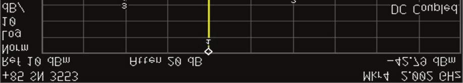
20 PHASE NOISE PERFORMANCE OF A 1GHz SO AT +25ºC (x2 MULTIPLICATION USED) 20 of 23


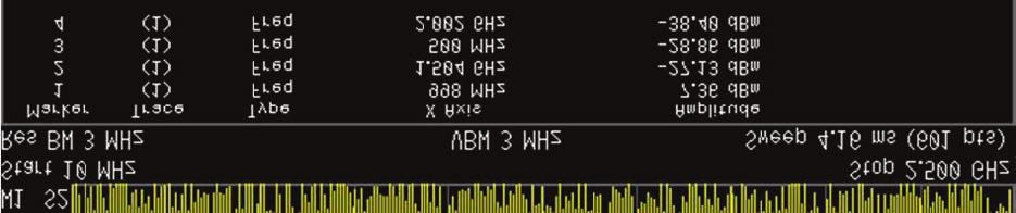
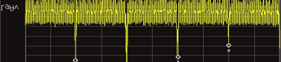
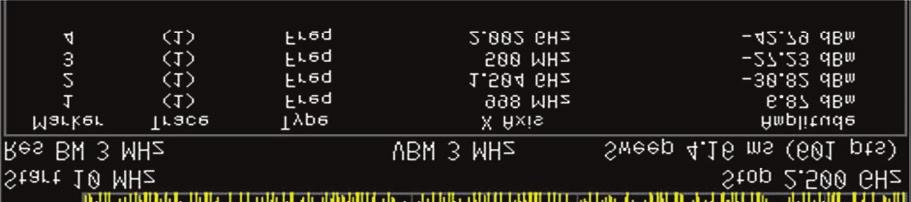
21 OUTPUT POWER SPECTRUM INCLUDING SUB-HARMONICS OF A 1GHz SO AT +25ºC OUTPUT POWER SPECTRUM INCLUDING SUB-HARMONICS OF A 1GHz SO AT +85ºC 21 of 23
22 FREQUENCY VERSUS TEMPERATURE CURVE ESD RATINGS Proper ESD precautions should be taken when handling and mounting semiconductor products. Built in ESD protection circuitry ratings are as follows: Model Minimum Conditions Human Body Model Class 1C, 2000V MIL-STD-883, Method of 23
23 DCO REV REVISION SUMMARY PAGE DATE 6558 C Remove phase noise plot at 500MHz 20 02/21/2017 Changed Phase Noise plot on page 20 to fix RMS Jitter (previously used unknown/incorrect integration bandwidth) 20 Changed breadboard option from BB to B D Fixed references of crystal oscillators/resonators to SAW /12/2017 Changed burn in period par Fix Typos All Remove Phase Noise testing over temperature (should only be 25 C) 11, 13, 14, of 23
GENERAL PRODUCT SPECIFICATION CONTROL DRAWING
 GENERAL PRODUCT SPECIFICATION CONTROL DRAWING Revision - A B C D DCO 328 Initial release Revise per DCO 328 Correct typos on para. 4.6.3 and Table l Add paragraphs 4.2.4 and 4.2.12 Corrections to Table
REVISION RECORD AND DESCRIPTION CONTINUED ON NEXT PAGE.
 REVISION RECORD REV DESCRIPTION DATE 0 INITIAL RELEASE 06/18/08 REVISION RECORD AND DESCRIPTION CONTINUED ON NEXT PAGE. CAUTION: ELECTROSTATIC DISCHARGE SENSITIVE PART REVISION PAGE NO. 1 2 3 4 5 6 7 8
REVISION RECORD AND DESCRIPTION CONTINUED ON NEXT PAGE.
 REVISION RECORD REV DESCRIPTION DATE 0 INITIAL RELEASE 06/12/96 A BURN-IN CIRCUIT CHANGED TO MATCH THE JAN BURN-IN CIRCUIT. 1/23/97 B PAGE 2, PARAGRAPH 3.3.b: ADDED (SEE PARAGRAPH 3.2). 10/17/98 PAGE 3,
MIL-PRF SUMMARY OF CHANGES FOR REVISION K November 15, 2017
 The following table summarizes the changes made to MIL-PRF-38534 Revision J resulting in MIL-PRF-38534 Revision K. REF No. 1 3 4 5 Paragraph Change Source Reason Page No. Cover page Add cover page to document.
00136 A DOC B. Oscillator Specification, Hybrid Clock REV DESCRIPTION DATE PREP APPD B CO /27/16 DF/SM LT
 REV DESCRIPTION DATE PREP APPD B CO-25877 1/27/16 DF/SM LT MOUNT HOLLY SPRINGS, PA 17065 THE RECORD OF APPROVAL FOR THIS DOCUMENT IS MAINTAINED ELECTRONICALLY WITHIN THE ERP SYSTEM Oscillator Specification,
PERFORMANCE SPECIFICATION HYBRID MICROCIRCUITS, GENERAL SPECIFICATION FOR
 INCH-POUND This document and process conversion measures necessary to comply with this revision shall be completed by 13 March 2011 MIL-PRF-38534H 13 September 2010 SUPERSEDING MIL-PRF-38534G 9 March 2009
DISTRIBUTION LIST CHANGE RECORD
 DISTRIBUTION LIST In charge of the document: L. LE ROY- Quality Director Copy to: Responsibility P. MAURICE President P.E. BERTHET Marketing and Sales Director P. RIGOBERT Manufacturing Director N. FIANT
PRELIMINARY. HTHA (Z1-Foil)
") Ultra High Precision Z1-Foil Technology Chip Resistor for Hybrid Circuits with Aluminum Wire Bonding for High Temperature Applications up to +240 C, Long Term Stability of 0.05%, TCR to ± 1ppm/ C INTRODUCTION
Ultra High Precision Z1-Foil Technology Chip Resistor for Hybrid Circuits with Aluminum Wire Bonding for High Temperature Applications up to +240 C, Long Term Stability of 0.05%, TCR to ± 1ppm/ C INTRODUCTION
HTHA (Z1-Foil) Vishay Foil Resistors
 Vishay Foil Resistors") Ultra High Precision Z1-Foil Technology Chip Resistor for Hybrid Circuits with Aluminum Wire Bonding for High Temperature Applications up to +240 C, Long Term Stability of 0.05%, TCR to ± 1ppm/ C INTRODUCTION
Ultra High Precision Z1-Foil Technology Chip Resistor for Hybrid Circuits with Aluminum Wire Bonding for High Temperature Applications up to +240 C, Long Term Stability of 0.05%, TCR to ± 1ppm/ C INTRODUCTION
Quality and Reliability Report
 Quality and Reliability Report Product Qualification MAAM-008819 2mm 8-Lead PDFN Plastic Package QTR-0147 M/A-COM Technology Solutions Inc. 100 Chelmsford Street Lowell, MA 01851 Tel: (978) 656-2500 Fax:
PRELIMINARY. FRSH Series (0603, 0805, 1206, 1506, 2010, 2512) (Z1-Foil) Vishay Foil Resistors
 (Z1-Foil) Vishay Foil Resistors") Ultra High Precision Foil Wraparound Surface Mount Chip Resistor with Extended Pads for High Power/High Temperature Applications up to +225 C, Load Life Stability of 0.05%,TCR to ± 1ppm/ C INTRODUCTION
Ultra High Precision Foil Wraparound Surface Mount Chip Resistor with Extended Pads for High Power/High Temperature Applications up to +225 C, Load Life Stability of 0.05%,TCR to ± 1ppm/ C INTRODUCTION
SPR-54 Series. Data Sheet. Outline. Features. Viewing angle 2θ 1/2 : 45. Recommended Solder Pattern. Dimensions. Specifications. 1/ Rev.
 Features Outline Viewing angle 2θ 1/2 : 45 Color Type M V Dimensions Recommended Solder Pattern 1.0 ±0.1 2.0 2.5 2.5 Tolerance : 0.2 (unit : mm) (unit : mm) Specifications Viewing angle 2θ 1/2 / 45 :Standard
ATC ATC. Commercial Off-the-Shelf (COTS) Commercial Off The Shelf. High Reliability Certification Program. Applications:
 Commercial Off The Shelf. High Reliability Certification Program. Applications:") ATC High Reliability Program Commercial Off The Shelf ATC Commercial Off-the-Shelf (COTS) High Reliability Program HA HB HC HD A Cost Effective approach to qualifying standard products for enhanced reliability
ATC High Reliability Program Commercial Off The Shelf ATC Commercial Off-the-Shelf (COTS) High Reliability Program HA HB HC HD A Cost Effective approach to qualifying standard products for enhanced reliability
FRSM Series (Z1 Foil Technology)
") (Z1 Foil Technology) UltraHigh-PrecisionFRSMWrap-AroundChipResistors,Z1FoilTechnologyConfiguration Resistors, Z1 Foil Technology Configuration with TCR of ±0.05 ppm/ C and Improved Load-Life Stability
(Z1 Foil Technology) UltraHigh-PrecisionFRSMWrap-AroundChipResistors,Z1FoilTechnologyConfiguration Resistors, Z1 Foil Technology Configuration with TCR of ±0.05 ppm/ C and Improved Load-Life Stability
nicrom e l e c t r o n i c
 G E N E R A L High Performance Thick Film Resistors C A T A L O G 3 Nicrom Electronic Via Roncaglia CH - 6883 Novazzano SWITZERLAND Phone : ++4 () 9 68 99 86 Fax : ++4 () 9 68 99 86 info@nicrom-electronic.com
Technical Requirements for Electronic Parts, Materials, and Processes Used in Space and Launch Vehicles
 AEROSPACE REPORT NO. TOR-2006(8583)-5236 Technical Requirements for Electronic Parts, Materials, and Processes Used in Space and Launch Vehicles 13 November 2006 Prepared by S. R. ROBERTSON, L. I. HARZSTARK,
SML-S13RT. Datasheet. Outline. Features. Surface mount Lens LEDs. Narrow directivity and high brightness. Availability of reverse mounting
 Datasheet Features Outline Surface mount Lens LEDs Narrow directivity and high brightness Availability of reverse mounting Size 3216(1206) size 3.2 1.6mm (t=1.85mm) Color Type R Dimensions Recommended
Quality and Reliability Report
 Quality and Reliability Report Product Qualification MASW-007921 2mm 8-Lead Plastic Package QTR-0148 M/A-COM Technology Solutions Inc. 100 Chelmsford Street Lowell, MA 01851 Tel: (978) 656-2500 Fax: (978)
Data Bus Connector and Terminator Requirements Document DB-1001-A. Revision C
 Data Bus Connector and Terminator Requirements Document DB-1001-A Revision C 2507 W. Geneva Dr. Tempe, Arizona 85282 Phone [602] 231-8616 FAX [602] 273-9135 www.phxlogistics.com TABLE OF CONTENTS 1. Introduction
Reference Only. Spec. No. JENF243D-0006K-01 P 1/ 8
 Spec. No. JENF243D-0006K-01 P 1/ 8 Chip EMIFIL LC Combined Monolithic NFL21SP X1C Reference Specification 1. Scope This reference specification applies to Chip EMIFIL LC Combined Monolithic Type NFL21S
DATA SHEET Metal Element Current Sensing Chip Resistor CLS Series
 DATA SHEET Metal Element Current Sensing Chip Resistor 0.5% TO 5%, TCR ±25 TO ±450 SIZE: 1206/2010/2512/2725/2728/4527/4527S RoHs Compliant 14 October, 2016 V.4 DS-ENG-007 23 Page: 2 of 1. SCOPE 1.1 This
Review of US Air Force Parts, Materials and Processes (PMP) Requirements
 Requirements") Review of US Air Force Parts, Materials and Processes (PMP) Requirements Page 1 Larry Harzstark Dr. Steven Robertson The Aerospace Corporation (310) 336-5883 10-16-09 Topics of Discussion Introduction
Review of US Air Force Parts, Materials and Processes (PMP) Requirements Page 1 Larry Harzstark Dr. Steven Robertson The Aerospace Corporation (310) 336-5883 10-16-09 Topics of Discussion Introduction
Description. Applications
 3.5x2.8mm SURFACE MOUNT LED LAMP Features Package Dimensions ATTENTION OBSERVE PRECAUTIONS FOR HANDLING ELECTROSTATIC DISCHARGE SENSITIVE DEVICES Industry standard PLCC-4 package. High reliability LED
PERFORMANCE SPECIFICATION RESISTOR, CHIP, FIXED, FILM, NONESTABLISHED RELIABILITY, ESTABLISHED RELIABILITY, SPACE LEVEL, GENERAL SPECIFICATION FOR
 INCH-POUND MIL-PRF-55342H 5 September 2017 SUPERSEDING MIL-PRF-55342H w/ Amendment 4 29 January 2016 PERFORMANCE SPECIFICATION RESISTOR, CHIP, FIXED, FILM, NONESTABLISHED RELIABILITY, ESTABLISHED RELIABILITY,
REVISIONS LTR DESCRIPTION DATE (YR-MO-DA) APPROVED. A Update drawing to the latest requirements of MIL-PRF gc Charles F.
 APPROVED. A Update drawing to the latest requirements of MIL-PRF gc Charles F.") REVISIONS LTR DESCRIPTION DTE (YR-MO-D) PPROVED Update drawing to the latest requirements of MIL-PRF-38534. gc 18-03-12 Charles F. Saffle REV REV REV STTUS REV OF S 1 2 3 4 5 6 7 8 PMIC N/ STNDRD MICROCIRCUIT
REVISIONS LTR DESCRIPTION DTE (YR-MO-D) PPROVED Update drawing to the latest requirements of MIL-PRF-38534. gc 18-03-12 Charles F. Saffle REV REV REV STTUS REV OF S 1 2 3 4 5 6 7 8 PMIC N/ STNDRD MICROCIRCUIT
MIL-PRF-39035, Char. H with a Smooth and Unidirectional Output
 Bulk Metal Foil Ultra High Technology Precision Trimming Potentiometers, 3 / 8 " Square, RJ24 Style, Designed to Meet or Exceed the Requirements of MIL-PRF-39035, Char. H with a Smooth and Unidirectional
PERFORMANCE SPECIFICATION RESISTOR, CHIP, FIXED, FILM, ZERO OHM, INDUSTRIAL, HIGH RELIABILITY, SPACE LEVEL, GENERAL SPECIFICATION FOR
 INCH-POUND MIL-PRF-32159 18 August 2017 SUPERSEDING MIL-PRF-32159 w/ Amendment 4 21 February 2013 PERFORMANCE SPECIFICATION RESISTOR, CHIP, FIXED, FILM, ZERO OHM, INDUSTRIAL, HIGH RELIABILITY, SPACE LEVEL,
Topview 5630 Red SMD LED
 Topview 5630 Red SMD LED 1. Features - Chip High-Luminosity SMD LED - 5.6 x 3.0 x 0.9 mm (L x W x H), 4-Pin, Small Size Surface Mount Type - Wide Viewing Angle - Long Operating Life - MSL 3 2. Applications
Parameter Symbol Value Unit. Operating Temperature Top -40 To +100 C. Storage Temperature Tstg -40 To +120 C. Parameter Symbol Value Unit
 PRELIMINARY SPEC Part Number: KT-3228ZG10ZS-RV Green ATTENTION OBSERVE PRECAUTIONS FOR HANDLING ELECTROSTATIC DISCHARGE SENSITIVE DEVICES Absolute Maximum Ratings at TA = 25 C Parameter Symbol Value Unit
RF Transformer (Stabilized Matching Device) SMST18 series
 SMST18 series") 1 Features RF Transformer Stabilized Matching Device is RF impedance matching component. You can adjust impedance matching easily between antenna and feeding point, when you use RF Transformer. RF Transformer
1 Features RF Transformer Stabilized Matching Device is RF impedance matching component. You can adjust impedance matching easily between antenna and feeding point, when you use RF Transformer. RF Transformer
Reference Only. 2.Part Numbering (ex) NF Z 5B BW 2R9 L N 1 0 L
 NF Z 5B BW 2R9 L N 1 0 L") SpecNo.JENF243J-0011A-01 P1/10 CHIP NOISE FILTER NFZ5BBW LN10 REFERENCE SPECIFICATION 1.Scope This reference specification applies to NFZ5BBW_LN10L Series, Chip Noise Filter. 2.Part Numbering (ex) NF Z
SpecNo.JENF243J-0011A-01 P1/10 CHIP NOISE FILTER NFZ5BBW LN10 REFERENCE SPECIFICATION 1.Scope This reference specification applies to NFZ5BBW_LN10L Series, Chip Noise Filter. 2.Part Numbering (ex) NF Z
SMD Technical Data Sheet High Power Green LED LH5070GCZ1.LW01
 SMD Technical Data Sheet High Power Green LED LH5070GCZ1.LW01 Features High power green LED ( 7.0 x 5.0 x 1.3 mm ) Lead frame package with individual 6 pins 1 chip inside 1 zener inside Wide view angle
Z Series (Z-Foil) Vishay Foil Resistors.
 Vishay Foil Resistors.") Z Series (Z-Foil) Ultra High Precision Z-Foil Resistor with TCR of ± 0.05 ppm/ C, Tolerance of ± 0.005 % (50 ppm), Load Life Stability of ± 0.005 %, ESD Immunity up to 25 kv and Thermal EMF of 0.05 µv/
Z Series (Z-Foil) Ultra High Precision Z-Foil Resistor with TCR of ± 0.05 ppm/ C, Tolerance of ± 0.005 % (50 ppm), Load Life Stability of ± 0.005 %, ESD Immunity up to 25 kv and Thermal EMF of 0.05 µv/
Aerospace Products. Quality Flows. 1. Introduction
 1. Introduction Design and manufacturing facilities meet international quality standards. For Space, Avionic and Military Projects, production screenings and qualification are compliant either with ESCC
SML-P11 Series PICOLED TM -eco
 PICOLED TM -eco Features Outline Ultra compact, thin size 1.0 0.6mm, t=0.2mm Accomplishes low power consuming application specification assured at I F =1mA Size 1006 1006 (0402) (0402) 1.0 0.6mm 1.0 0.6mm
DESIGN VERIFICATION TEST REPORT ERCDA SS-TD-TU. Mated with ERF L-DV-L
 Project Number: Tracking Code: TC0810--1621 Requested by: John Riley Date: 05/27/2008 Product Rev: 0 Part #: ERCDA-25-09.00-1SS-TD-TU Lot #: N/A Tech: Eric Fox & Daniel Borgelt Eng: Troy Cook Qty to test:
Features. Benefits. Min Typical Max Min Max. OPTAN-250H-BL 245 nm 250 nm 255 nm 0.5 mw 1.0 mw. OPTAN-255H-BL 250 nm 255 nm 260 nm 0.5 mw 1.
 DATA SHEET OPTAN BALL LENS UVC LEDS IN A TO-39 PACKAGE WHICH OFFERS SUPERIOR LIGHT OUTPUT, EXCELLENT SPECTRAL QUALITY AND LONG LIFETIMES. AVAILABLE IN PEAK WAVELENGTHS FROM 25 nm-28 nm AND OPTICAL OUTPUT
10 Manor Parkway, Suite C Salem, New Hampshire
 Micro-Precision Technologies (MPT) is an independent manufacturer of hybrid integrated circuits, multichip modules, and high-precision thick film substrates for the military, medical, avionics, optoelectronics,
Long-term reliability of SiC devices. Power and Hybrid
 Long-term reliability of SiC devices Power and Hybrid Rob Coleman Business Development and Applications Manager TT electronics, Power and Hybrid Roger Tall Product Specialist Charcroft Electronics Ltd
GaAs MMIC Space Qualification
 GaAs MMIC Space Qualification GaAs MMIC Testing TriQuint Semiconductor has advanced Lot Acceptance Testing (LAT) for High Reliability Applications of GaAs MMICs. A flowchart depicting the entire MMIC processing
Supplier Quality Requirements Q Clauses
 Supplier Quality Requirements Q Clauses QA-0100032-Rev D DCR# 1603139 4/8/16 The following supplier quality requirements (Q Clauses), when specifically referenced in the Purchase Order by number, form
SUPPLIER QUALITY PROCUREMENT REQUIREMENTS
 THIS DOCUMENT ESTABLISHES THE FLOW-DOWN QUALITY ASSURANCE REQUIREMENTS OF PROCUREMENT FROM WINONICS CUSTOMERS TO OUR SUPPLIERS. 1. QUALITY PROGRAM REQUIREMENTS Supplier shall provide and maintain a quality
QUALITY ASSURANCE PROCUREMENT PROVISIONS
 ESAM, INC. QUALITY ASSURANCE PROCUREMENT PROVISIONS QAPP s escription of Change Date A Initial Release 10/1/2014 B Revised QAPP 12 to require 1/20/2016 written approval C Added QAPP 18.B 5/19/2016 D Revised
Military Attenuator Module
 Military Attenuator Module Actual size: 2.28 x 2.4 x 0.5in 57,9 x 61,0 x 12,7mm MI-RAM Ripple Attenuator Module Features & Benefits Reduces output PARD to 10mVp-p Full attenuation up to 20A load No adjustments
MAR 17 Rev B1
 Product Specification 108-151010 01 MAR 17 Rev B1 DTM Series Connector System 1. SCOPE 1.1. Content This specification covers performance, tests and quality requirements for the TE Connectivity (TE) DTM
5W White SPHWHTA3N500
 Product Family Data Sheet Rev. 00 2016.11.01 111 High Power LED Ceramic Series 5W White SPHWHTA3N500 Features & Benefits Package : Silicone covered ceramic substrate Dimension : 3.5 mm x 3.5 mm Technology
Extended-Frequency SMA Connectors
 Extended-Frequency SM Connectors Extended-Frequency SM Connectors This brochure introduces two new series of connectors that extend SM performance beyond the MIL-PRF-39012 upper frequency limit of 18 GHz,
No.JEMCP B a)equivalent Circuit 5.Rated value MURATA PART NO. NFM2CC0UH3D NFM2CC02RH3D (3) Nominal Capacitance Capacitance Tolerance
equivalent Circuit 5.Rated value MURATA PART NO. NFM2CC0UH3D NFM2CC02RH3D (3) Nominal Capacitance Capacitance Tolerance") No.JEMCP0-00863B CHIP EMIFIL CHIP 3-TERMINAL CAPACITOR FOR GENERAL NFM2CC Series Reference Sheet.Scope 2.Reference PART No. List 2 3 4 5 6 7 8 3.MURATA Part NO. System (Ex.) This product specification
No.JEMCP0-00863B CHIP EMIFIL CHIP 3-TERMINAL CAPACITOR FOR GENERAL NFM2CC Series Reference Sheet.Scope 2.Reference PART No. List 2 3 4 5 6 7 8 3.MURATA Part NO. System (Ex.) This product specification
Measurement data at orders of magnitude lower cost than other techniques BENEFITS Simple UVC source ideal for compact sensors
 Optan The Optan Ball Lens, with integrated focusing optics, is the first choice for discerning professionals developing sensors and instruments in demanding measurement applications. Designed for and proven
V D Y. Recommended Solder Pattern. Tolerance : ±0.2 (unit : mm) Absolute Maximum Ratings (Ta=25ºC) Reverse Operating Temp. Storage Temp.
 Absolute Maximum Ratings (Ta=25ºC) Reverse Operating Temp. Storage Temp.") SLR-56x Series Data Sheet Features Viewing angle 2θ 1/2 : 40 Outline Color Type V D Y M Dimensions Recommended Solder Pattern 5.5 φ5.0 ±0.1 2.0 8.7 2.5 or 5.0 0.5 24.0Min. (2.5) Cathode Tolerance : ±0.2
SLR-56x Series Data Sheet Features Viewing angle 2θ 1/2 : 40 Outline Color Type V D Y M Dimensions Recommended Solder Pattern 5.5 φ5.0 ±0.1 2.0 8.7 2.5 or 5.0 0.5 24.0Min. (2.5) Cathode Tolerance : ±0.2
Product Specification JUL 14 Rev. A1
 Industrial SCSI Connector 1. Scope 1.1 Contents This specification covers the requirements for product performance, test methods and quality assurance provisions of SCSI Connector. 2. Applicable Documents
RESD1CANFH Transient Voltage Suppressor (AEC-Q101 qualified) Data sheet
 Data sheet") RESD1CANFH Transient Voltage Suppressor (AEC-Q101 qualified) Data sheet V RWM 24 V P PP 350 W V CL 44 V Outline Features Small mold type High reliability Inner Circuit Application Packaging Specification
RESD1CANFH Transient Voltage Suppressor (AEC-Q101 qualified) Data sheet V RWM 24 V P PP 350 W V CL 44 V Outline Features Small mold type High reliability Inner Circuit Application Packaging Specification
Reliability Qualification Report
 Reliability SUF-1000 SUF-2000 SUF-3000 SUF-4000 SUF-5000 The information provided herein is believed to be reliable at press time. Sirenza Microdevices assumes no responsibility for inaccuracies or omissions.
Metal Film Resistors, Industrial, Precision
 Metal Film Resistors, Industrial, Precision FEATURES Small size - conformal coated Flame retardant epoxy coating Controlled temperature coefficient Available Excellent high frequency characteristics Exceptionally
Quality Supplier Requirements for Beckwith Electric Co., Inc.
 Quality Supplier Requirements for Beckwith Electric Co., Inc. This Page Left Intentionally Blank To Our Valued Suppliers: One of the primary goals of Beckwith Electric is to provide the highest Quality
Reference Only. Chip Ferrite Bead BLM31 SZ1 Murata Standard Reference Specification [AEC-Q200]
![Reference Only. Chip Ferrite Bead BLM31 SZ1 Murata Standard Reference Specification [AEC-Q200]](/thumbs/76/73993812.jpg "Reference Only. Chip Ferrite Bead BLM31 SZ1 Murata Standard Reference Specification [AEC-Q200]") P.1/9 Chip Ferrite Bead BLM31 SZ1 Murata Standard Reference Specification [AEC-Q200] 1. Scope This reference specification applies to Chip Ferrite Bead for Automotive Electronics BLM31_SZ Series based
P.1/9 Chip Ferrite Bead BLM31 SZ1 Murata Standard Reference Specification [AEC-Q200] 1. Scope This reference specification applies to Chip Ferrite Bead for Automotive Electronics BLM31_SZ Series based
Reference Only. Chip Ferrite Bead BLM31 SH1L Murata Standard Reference Specification [AEC-Q200]
![Reference Only. Chip Ferrite Bead BLM31 SH1L Murata Standard Reference Specification [AEC-Q200]](/thumbs/72/66825468.jpg "Reference Only. Chip Ferrite Bead BLM31 SH1L Murata Standard Reference Specification [AEC-Q200]") P.1/9 Chip Ferrite Bead BLM31 SH1L Murata Standard Reference Specification [AEC-Q200] 1. Scope This reference specification applies to Chip Ferrite Bead for Automotive Electronics BLM31_SH Series based
P.1/9 Chip Ferrite Bead BLM31 SH1L Murata Standard Reference Specification [AEC-Q200] 1. Scope This reference specification applies to Chip Ferrite Bead for Automotive Electronics BLM31_SH Series based
Tantalum Wet Electrolytic Capacitor
 INTRODUCTION The structure of a Tantalum Wet Electrolytic Capacitor consists of four main elements: a primary electrode (anode), dielectric, a secondary electrode system (cathode) and a wet (liquid) electrolyte.
1/2W, 0805 Low Resistance Chip Resistor (Lead / Halogen free)
") 1. Scope 1/2W, 0805 (Lead / Halogen free) This specification applies to 1.2mm x 2.0mm size 1/2W, fixed metal film chip resistors rectangular type for use in electronic equipment. 2. Type Designation RL
1. Scope 1/2W, 0805 (Lead / Halogen free) This specification applies to 1.2mm x 2.0mm size 1/2W, fixed metal film chip resistors rectangular type for use in electronic equipment. 2. Type Designation RL
DC-DC Converters MI-J00
 DC-DC Converters MI-J00 10 to 50 Watts Features & Benefits Inputs: 28V DC per MIL-STD-704D/E/F 155V DC per MIL-STD-1399A 270V DC per MIL-STD-704D/E/F Single output: 2 48V DC Up to 23W/in 3 MIL-STD-810
Sidelooker Infrared LED IR928-6C-F
 Features High reliability High radiant intensity Peak wavelength λp=940nm 2.54mm lead spacing Low forward voltage Pb free This product itself will remain within RoHS compliant version. Compliance with
SUPPLIER QUALITY CODES
 Supplier Quality s D07-00125 Rev A APPROVALS NAME AND TITLE SIGNATURE DATE M.G. Blankenship Senior Director, Operations I. Jimenez Materials Manager D07-00125-02 Page 1 of 5 SQC 1 SQC 2 SQC 3 SQC 4 SQC
Design Qualification Test Report SMS/TMS SMS L-D/TMS L-D
 Project Number: Design Qualification Test Report Tracking Code: 147211_Report_Rev_1 Requested by: Joe Smallwood Date: 11/11/2011 Product Rev: 0 Lot #: N/A Tech: Peter Chen Eng: Vico Zhao Qty to test: 45
INSULATED JOINTS. Monolithic Joints for Electrically Isolating Pipelines
 INSULATED JOINTS Monolithic Joints for Electrically Isolating Pipelines INSULATED JOINTS TUBE TURNS INSULATED JOINTS are a pre-fabricated, non-separable, union used to isolate specific sections of pipelines
DEPARTMENT OF DEFENSE HANDBOOK DOSE-RATE HARDNESS ASSURANCE GUIDELINES
 NOTICE OF CHANGE METRIC MIL-HDBK-815 10 January 2002 DEPARTMENT OF DEFENSE HANDBOOK DOSE-RATE HARDNESS ASSURANCE GUIDELINES TO ALL HOLDERS OF MIL-HDBK-815: 1. THE FOLLOWING PAGES OF MIL-HDBK-815 HAVE BEEN
Specification of SAW Filter
 SFC3213-0 RoHS Compliant Specification of SAW Filter Part No. : SF1-0915M5UUA1 Oct., 1, 201 Kyocera Corporation, Electronic Components Group, Circuit Device Dept. Approved by H. Arikawa Design Engineering
Dallas Semicoductor DS80C320 Microcontroller
 Construction Analysis Dallas Semicoductor DS80C320 Microcontroller Report Number: SCA 9702-525 Global Semiconductor Industry the Serving Since 1964 15022 N. 75th Street Scottsdale, AZ 85260-2476 Phone:
LT Industries SQFR 101
 Page 1 of 5 LT Industries SQFR 101 Supplier Quality Flow down Requirements 1.0 GENERAL REQUIREMENTS: The supplier must flow down these requirements from LTI to their sub tier suppliers whenever those sub
General Purpose Chip Resistors MCMR Series
 Description The resistors are constructed in a high grade ceramic body (aluminium oxide). Internal metal electrodes are added at each end and connected by a resistive paste that is applied to the top surface
Features Small size Low insertion loss High selectivity Hermetic seal. 1000MHz MHz. 1500MHz MHz. 1795MHz MHz.
 SAW Filters RF SAW Filters for TDSCDMA SF15 Series (Diplex Type Dual Filter) Features Small size Low insertion loss High selectivity Hermetic seal Applications TDSCDMA How to Order SF 15 19 T A SB A1 1
WorkShop Audace. INSA ROUEN 8 juin 2012
 WorkShop Audace INSA ROUEN 8 juin 2012 Global Standards for the Microelectronics Industry JEDEC standards for product level qualification Christian Gautier Content JEDEC overview Environmental reliability
Rosen Aviation Supplier Quality Assurance Requirements
 1. Purpose This document establishes the Quality Assurance Requirements for all Rosen Suppliers. This document is applicable to all Rosen Aviation Purchase Orders (POs). In addition to the requirements
RTD Simulator. Handy Resistor Simulates RTD Temperature Outputs, such as PT-100 and PT Vishay Foil Resistors FEATURES AND BENEFITS
 Handy Resistor Simulates RTD Temperature Outputs, such as PT-100 and PT-1000 FEATURES AND BENEFITS Temperature coefficient of resistance (TCR): 55 to +125, 25 ref. RTD simulator (C): ±2 ppm/ typical (see
Cal-Chip Electronics, Incorporated Thick Film Chip Resistors - RM Series
 Thick Film Chip Resistors - RM Series Fixed Chip Resistors manufactured for more compact electronic components and automatic mounting system. These Chip Resistors have electrical stability and mechanical
DEPARTMENT OF DEFENSE
 INCH-POUND MIL-STD-202H 18 April 2015 SUPERSEDING MIL-STD-202G w/change 2 28 June 2013 DEPARTMENT OF DEFENSE TEST METHOD STANDARD ELECTRONIC AND ELECTRICAL COMPONENT PARTS AMSC N/A FSC 59GP FOREWORD 1.
5mm Round Standard T-1 3/4 Type Full Color Blinking LED Technical Data Sheet. Part No.: LL-F506RGBC2E-F2
 5mm Round Standard T-1 3/4 Type Full Color Blinking LED Technical Data Sheet Part No.: LL-F506RGBC2E-F2 Spec No.: B508 X335 Rev No.: V.2 Date: Mar./20/2006 Page: 1 OF 9 Features: Single lamp with 3 original
QUALITY MANUAL QM0492 AS9100 SUPPLEMENT II
 QUALITY MANUAL QM0492 AS9100 SUPPLEMENT II REV E Foreword This document defines the quality management system requirements to be applied in facilities registered to the aerospace standard AS9100. This
Reference Only. Spec. No. JENF243E-0003Q-01 P 1 / 8. Chip EMIFIL LC Combined Type for Large Current NFE61PT 1H9 Reference Specification
 Spec. No. JENF243E-0003Q-01 P 1 / 8 Chip EMIFIL LC Combined Type for Large Current NFE61PT 1H9 Reference Specification 1. Scope This reference specification applies to Chip EMIFIL LC Combined Type for
Supplier Quality Manual
 ALLIANCE ELECTRONICS DISTRIBUTOR Supplier Quality Manual 22412 Gilberto Rd. Rancho Santa Margarita, CA 92688 INTRODUCTION Welcome to Alliance Electronics Distributor (AED) Alliance Electronics Distributor
UVTOP280-FW-SMD. Description. Maximum Rating (T CASE = 25 C) Electro-Optical Characteristics (T CASE = 25 C, I F = 20 ma)
 Electro-Optical Characteristics (T CASE = 25 C, I F = 20 ma)") v2.0 11/2017 UVTOP280-FW-SMD Deep Ultraviolet Light Emission Source 285 nm, 2.0 mw 3535 Ceramic SMD Package Low Thermal Resistance Chemical and Biological Analysis Description UVTOP280-FW-SMD is a deep
v2.0 11/2017 UVTOP280-FW-SMD Deep Ultraviolet Light Emission Source 285 nm, 2.0 mw 3535 Ceramic SMD Package Low Thermal Resistance Chemical and Biological Analysis Description UVTOP280-FW-SMD is a deep
MIL System Overview EEE Parts
 1 MIL System Overview EEE Parts CONTENT 2 MIL system & DSCC MIL system & documentation MIL-STD example: MIL-STD-883 Screening tests Qualification and Quality Conformance Procedures General Specifications
RT8725. Single-Phase BLDC Fan Driver IC. Features. General Description. Applications
 RT8725 Single-Phase BLDC Fan Driver IC General Description The RT8725 is a single-phase driver IC for fan motors. Rotation speed is controlled by input signal. The RT8725 provides several protection features
SUPPLIER QUALITY REQUIREMENTS QA-401
 SUPPLIER QUALITY REQUIREMENTS QA-401 115 Bay State Drive Braintree, MA 02184-5205 (781) 848-3400 FAX: (781) 843-2153 CONTENTS Section/Para Page 1.0 OVERVIEW... 3 1.1 PURPOSE... 3 1.2 THE COMPANY QUALITY
Gamma-ray Large Area Space Telescope (GLAST) Large Area Telescope (LAT) Parts Program Control Plan
 Large Area Telescope (LAT) Parts Program Control Plan") Document # Date Effective LAT-MD-00099-1 18 March 2001 Prepared by(s) Supersedes Nick Virmani None GLAST LAT SYSTEM SPECIFICATION Document Title LAT Parts Program Control Plan Subsystem/Office LAT System
Document # Date Effective LAT-MD-00099-1 18 March 2001 Prepared by(s) Supersedes Nick Virmani None GLAST LAT SYSTEM SPECIFICATION Document Title LAT Parts Program Control Plan Subsystem/Office LAT System
TOSHIBA LED Lamp TLCBD1060(T18) Storage Temperature T stg ( C) TLCBD to to 100. Power Dissipation P D (mw)
 Storage Temperature T stg ( C) TLCBD to to 100. Power Dissipation P D (mw)") TOSHIBA LED Lamp TLCBD60(T18) Panel Circuit Indicator Unit: mm Surface-mount devices 2.2 (L) 1.4 (W) 1.3 (H) mm LED chip + phosphor Color: ICE Blue Cx=0.20(typ), Cy=0.30(typ), 90 mcd(typ.) @ma Low drive
TOSHIBA LED Lamp TLCBD60(T18) Panel Circuit Indicator Unit: mm Surface-mount devices 2.2 (L) 1.4 (W) 1.3 (H) mm LED chip + phosphor Color: ICE Blue Cx=0.20(typ), Cy=0.30(typ), 90 mcd(typ.) @ma Low drive
DEPARTMENT OF DEFENSE STANDARD PRACTICE
 NOT MEASUREMENT SENSITIVE MIL-STD-790G 24 January 2013 SUPERSEDING MIL-STD-790G 13 September 2011 DEPARTMENT OF DEFENSE STANDARD PRACTICE ESTABLISHED RELIABILITY AND HIGH RELIABLITY QUALIFIED PRODUCTS
SECTION RADIO FREQUENCY SHIELDING ENCLOSURE RF Welded System
 SECTION 13096 RADIO FREQUENCY SHIELDING ENCLOSURE RF Welded System Prepared by: 90 Dayton Avenue, Unit 4B, Suite 13 Passaic, NJ 07055 (973) 574-9077 13096-1 RF WELDED SYSTEM PART 1 GENERAL 1.1 SECTION
High power chip resistors < Wide terminal type > LTR series
 High power chip resistors < Wide terminal type > LTR series Features 1)High joint reliability with long side terminations. 2)Highest power ratings in their class. 3)Guaranteed anti-surge characteristic
1/2W, 0612 Low Resistance Chip Resistor (Lead / Halogen Free)
") 1/2W, 0612 (Lead / Halogen Free) 1. Scope This specification applies to 1.6mm x 3.2mm size 1/2W, fixed metal film chip resistors rectangular type for use in electronic equipment. 2. Type Designation RL1632W
1/2W, 0612 (Lead / Halogen Free) 1. Scope This specification applies to 1.6mm x 3.2mm size 1/2W, fixed metal film chip resistors rectangular type for use in electronic equipment. 2. Type Designation RL1632W
Feb12 Rev D
 Product Specification AMPSEAL* Connectors 108-1329 01Feb12 Rev D 1. SCOPE 1.1. Content This specification covers performance, tests and quality requirements for AMPSEAL* connectors. 1.2. Qualification
Sulfur tolerant chip resistors
 Sulfur tolerant chip resistors TRR series Datasheet Features 1)Special construction prevents sulfur gas penetration, significantly increasing reliability. 2)ROHM resistors have obtained ISO91 / ISO / TS16949
Schottky Barrier Diode RBR5L30B
 Schottky Barrier Diode RBR5L3B Application Dimensions (Unit : mm) Land Size Figure (Unit : mm) General rectification 2.6±.5 2. 2. 5.3±..5 9.5±. 5.5±.5 2±.2.75±. Features ) Small power mold type (PMDS)
Quality System Document DOC #
 Page 2 of 9 Q ote Description AA AA1 AA2 AA3 AA4 AA5 AA6 AA7 AA8 AA9 AA10 AA11 AA12 AB AC AD AE AF AG AH AI AJ AK AL AM A AO AP AQ AR AS AT AU AV AW Universal Quality ote Quality Management System Quality
001 Inspection/Test Data Reports
 BAE Systems P.O. Box 15512 York, PA 17405-1512 9/20/16 Supplier Quality Notice 095871 Contract Deliverable Requirements Rev 09 This is to notify you of changes to BAE Systems CDR Manual. Please see the
SGS-Thomson M17C1001 1Mb UVEPROM
 Construction Analysis SGS-Thomson M17C1001 1Mb UVEPROM Report Number: SCA 9612-518 Global Semiconductor Industry the Serving Since 1964 15022 N. 75th Street Scottsdale, AZ 85260-2476 Phone: 602-998-9780
Surface Mount Sense Resistors
 Resistors Surface Mount Flexible leads for thermal expansion Open-air design reduces PCB heating Values down to 1milliohm Element TCR ±2ppm/ C Zero-ohm 65A jumper version RoHS compliant All parts are Pb-free
PPI/TZ Standard Quality Requirements for Suppliers -SQRS-
 PPI/TZ Standard Quality Requirements for Suppliers -SQRS- AS9100, ISO 13485 and ISO 9001 Revision: March 19, 2014 For questions concerning Standard Quality Requirements for Supplier (SQRS), please contact
Subcontractor Product Assurance Requirements L3-FOS
 Doc ID: QN-M02 Page 1 of 11 Rev # Date 0 5/08/13 1. SCOPE: QUALITY REQUIREMENTS FOR SM-3 BLK 1B & IIA PROGRAMS The contents of this subcontractor product assurance requirement document are applicable to
SMPM Female Cabled Connectors
 Product Specification 108-2326 28 APR 14 Rev B SMPM Female Cabled Connectors 1. SCOPE This specification covers performance, tests and quality requirements for the TE Connectivity (TE) Subminiature P Miniature
CONTACT ELECTRICAL CHARACTERISTICS TIGER CLAW CONTACT TESTING. A. Gas Tight
 CONTACT ELECTRICAL CHARACTERISTICS TIGER CLAW CONTACT TESTING A. Gas Tight 1. Purpose - To evaluate the integrity of the contact interface by assessment of the gas tight characteristics of the contacting