Using FEMAP on the NESC Composite Crew Module
|
|
|
- Jacob Jason McKenzie
- 6 years ago
- Views:
Transcription

1 , President, Structural Design & Analysis, Inc. Using FEMAP on the NESC Composite Crew Module Femap Symposium 2014 May 14-16, Atlanta, GA, USA Unrestricted Siemens AG 2014 FEMAP SYMPOSIUM 2014 Discover New Insights
2 Agenda What was the Composite Crew Module (CCM)? Design Overview Analysis Overview Analytical Tools Finite Element Models Flight Load Case Summary Critical Margins of Safety Full Scale Static Test Test Condition Selection Test Results Page 2


3 January 2007 NASA Administrator chartered the NESC to form an agency team to design and build a composite crew module, gain hands-on design, build, and test experience, in anticipation that future exploration system may be made of composite materials. Mike Kirsch


4 NESC Composite Crew Module As modeled in Pro-E As built in Iuka Page 4
5 Design Overview
 Main Chute I/F (3) Docking Windows (2) Tunnel Ceiling Conic Side Windows (2) Hatch Opening (1) Barrel Page")
6 Service Module/Alternate Launch Abort System (SM/ALAS) Fittings (6 pl ) Design Overview LIDS Ring Drogue Chute I/F (1) Gussets (6) Main Chute I/F (3) Docking Windows (2) Tunnel Ceiling Conic Side Windows (2) Hatch Opening (1) Barrel Page 6


7 System Dimensions Page 7


8 CEV Internal Packaging Backbone Packaging Crew Pallet Consoles Page 8
 Internal Pressure 50% load sharing on backbone Water Landing Page")
9 Lower Shell Loading Backbone carries pressure load no ring frame (~100 lbs savings) Membrane pressure head lobe shapes (~50 lbs savings) Leverages and enhances SM/ALAS reinforcements Backbone connection allows load sharing with Heat Shield (~1000 lbs heat shield savings) Internal Pressure 50% load sharing on backbone Water Landing Page 9


10 LIDS Interface Ring LIDS Interface Ring Supports TLI and Drogue parachute loads Bolted to Gusset Web and Caps 5 Tunnel taper to control bondline to tunnel Six discrete 60 doublers paste bonded to Ring and Tunnel Avoids high temperature cure with Aluminum Joint tested at element test level Discrete Doublers Page 10


11 Forward Bay Gusset Primary load path from shell to LIDS Ring Stabilizes ceiling, tunnel, and fwd bay Support and strength to Main Parachute fittings Provides hard points for Crew Pallet supports on IML Provides attachment structure for fwd bay subsystems Flat laminate panel and caps Pi-preforms bond shear webs to cap and shell Honeycomb panel Gusset Cap Pi-Preforms Page 11


12 Shell Face Sheets Mostly fabric with some uni Face sheets 4 plies minimum Solid 8 plies minimum Solid laminate to 70 plies Bearing pad-ups Integral beam caps Not to Scale: Ply Drops 20:1 Core Tapers 7 degree Page 12


 EA 9394 Potting")
13 Splice Pressure Shell Face sheet Pressure Shell Core Acreage Longeron Splice Doubler (non-autoclave cure) EA 9394 Potting Compound Page 13
14 Analysis Overview
15 Analytical Tools Model Pre- and Post-Processing done using FEMAP Nearly every PATRAN user converted to FEMAP once they saw what FEMAP could do and how easy it was to use NX and MSC NASTRAN used, depending on the analyst running the model HyperSizer used extensively for trade studies and margin writing, but FEMAP was used to maintain all analytical master models We learned how to make HyperSizer and FEMAP play nice together Fibersim was used extensively in design with data fed back to analysis Page 15
16 Master FEM Finite Element Models Coarse Mesh, overall loads/stiffness Detailed FEM Local Detailed Models (8+) Element & Component Test Models (4+) More than 15 models used to completely analyze the structure Page 16

")
17 Master FEM Contains about 29,400 elements, 27,250 nodes Overall Model CCM Portion Colors represent areas of constant lay-up (PCOMP) Page 17


18 Detailed FEM Contains over 200,000 nodes and elements Fairly fine mesh Includes: Covers Ply drops Fasteners Page 18


19 Detailed Finite Element Model Ply level detail throughout the model Page 19


20 Local Detailed FEMs Page 20


21 EDS, Lander CEV Loading Events Vehicles are not to scale. MOON 100 km Low Lunar Orbit Lander Performs LOI LOI Ascent Stage Expended Low Earth Orbit Earth Departure Stage Expended TLI At Burn Out TLI Initial Burn Reentry Service Module Expended EARTH Launch Entry and Landing Landing Page 21
22 Abort Conditions Extended Coast Period Stabilize Reorient & Fin Jettison Stabilize Descent using RCS Max q 65 kft 30 kft 18 kft Reduced Pitch Maneuver Reorient & Fin Jettison Jettison ACM Burnout Deploy Stabilize Controlled Coast Pitch Maneuver (using ACM) Jettison Tower/Shell & Deploy Chutes Abort motor fires, ACM & Roll RCS engage Pitch maneuver to achieve adequate separation & downrange Page 22


23 Loads Freebody Main Chute Load 64,400 lbs TLI Loads, 1.4 g s Drogue Load 34,200 lbs Launch Abort Load 134,000 lbs Maximum Internal Pressure, 31.1 psi Maximum Delta Load 76,000 lbs Service Module Load 101,000 lbs Water Landing, 28.2 g s Page 23


24 Critical Load Cases Abort, Pressure, Drogue & TLI Main Parachute Blast Overpressure Page 24
 LC601 +0.06 (Hoffman) LC937-0.")
25 Minimum Flight Margins (Pi Peak) LC (Hoffman) LC (Hoffman) LC (Hoffman) LC (Core Shear) LC601 Page 25
 LC302 +0.08 (Core Shear) LC601-0.")
26 Minimum Flight Margins (Shear/Tension) LC (Hoffman) LC (Hoffman) LC (Core Shear) LC (Shear/Tension) LC302 Page 26
27 Full-Scale Static Test
28 Goals & Objectives Test as much structure as possible Within schedule and budget constraints Test critical margins where possible Test in an order that best ensures success Predict strains in critical areas and use those areas for correlation to mathematical models Page 28

29 Test Set Up Page 29
30 Test Condition Selection Four conditions selected Maximum Internal Pressure (red) Most critical abort (High Altitude) (green) One Parachute Case (yellow) One Drogue Case (blue) And... Local Insert Case Page 30
31 Test Matrix Test Load Test Level Max Internal Pressure 15.5 psi Limit Abort, -Z SM/ALAS Fitting 15.5 psi/50 kips Limit Main Parachute, Fitting psi/46 kips Limit Max Internal Pressure 31.1 psi Ultimate Lower Shell Insert Test 5.3 kips Ultimate Drogue attach point 48 kips Ultimate Perform impacts at 18 critical locations 6 ft lbs Max Internal Pressure 31.1 psi Ultimate Main Parachute, Fitting psi/ 64 kips Ultimate 4x life cycling (22 pressure and 9 parachute) 17.1 psi/51 kips Limit + Perform impacts to lesser of barely detectable levels < /= 26 ft lbs 4x life cycling (22 pressure and 9 parachute) 17.1 psi/51 kips Limit + Max Internal Pressure, High Altitude Abort 32 + psi Failure Page 31


32 MicroStrain Static Test Results All conditions showed very good load match between predictions and strains SG301 SG302 SG303 SG451 SG452 SG Pred 302 Pred 303 Pred 451 Pred 452 Pred 551 Pred SG Pred Gages 551, 552 Tunnel IML Gages 301, 302, 303 Gages 451, 452 Percent Limit Load Page 32


33 Fiber Optic Layout Backbone Cap Longeron 5 Longeron Approximately 615 in/51.25 ft/ 1562 cm Approx 9 in of nonsensing fiber from end of connectors 3.6 Longeron B1a B1b Fiber routed 0.6 from edge of backbone cap Page 33
34 Fiber Optic Results Splice Splice/Backbone Cap Backbone Cap Max Pressure of Predicted Strains Max Pressure Predicted Strains Max Pressure Page 34


35 Failure Test Discussion
36 Bar Chart Definitions The Prediction Bar Chart summarizes the failure predictions for the burst test The bottom of the thin line represents the pressure that must be attained to demonstrate true ultimate performance of a particular failure mode and location Adjusting test pressure to account for temperature and moisture knockdowns The bottom of the colored bar represents our 99% failure prediction 99% of the population should exceed this value The top of the color bar represents the mean failure prediction The top half of the bar was not drawn on the chart, 50% of the structure would be expected to exceed the top of the chart The color of the bar represents the apparent severity of the failure mode Red = assumed catastrophic failure Yellow = assumed catastrophic failure mode, but low confidence in the actual predicted failure value Green = assumed benign failure mode, such as core yielding, bolt bearing, any mode where load would redistribute rather than a brittle failure Page 36
37 Pressure at Failure, psi Failure Predictions Page 37
38 Successful pressure test to failure! Failure occurred with internal pressure at 53.9 psi, nearly 340% limit load Large audible noise with immediate, but small pressure drop of 1 psi, followed by termination of supply pressure No sign of leakage and shell held vacuum during drain procedure No visible sign of failure internal or external Page 38 Sec 1-
39 Failure test cont d Load redistribution indicated by sudden change in measured strains No signs of anomalies on the lower shell even in repair areas No signs of anomalies around areas previously impacted to 26 foot pounds Validated that the CCM structure achieved design ultimate load after four times life cycling with known damage, repairs, and manufacturing anomalies Validated high altitude abort condition on backbone beams beyond design ultimate load level (41 psi) Validated vacuum pressure to beyond design ultimate load Splice joint, pi joints, and docking tunnel joints exceeded minimum design criteria Page 39 Sec 1-

40 MicroStrain Docking Window Strains Docking Windows 9000 SG306 SG307 SG312 Gage 567 Gage 560 These gages are in areas of strain gradient 8000 SG560 SG559 Gage SG Pred 307 Pred 312 Pred Gage Pred 559 Pred 567 Pred Gage 307 Gage Percent Limit Load Page 40


41 MicroStrain Shoulder Radius OML Shoulder Radius OML 1500 Gage 305 Gage Gage SG407 SG458 0 SG SG305 SG352 SG Pred 458 Pred 502 Pred 305 Pred 352 Pred Gage Pred Gage 407 Gage Percent Limit Load Page 41
42 MicroStrain Pressure, Psi Shoulder Radius OML Shoulder Radius OML Ceiling Disbond Supply Valve Closed Dump Valve Opened SG305, Bay A SG352, Bay B SG407, Bay C SG458, Bay D SG502, Bay E SG558, Bay F Official Pressure Time (Frame) Page 42


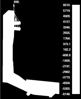
43 Core Stress (Non-Linear) at Failure Ld Through-Transmission Ultrasound OML thermography IML thermography Page 43
44 Summary/Conclusions CCM Design was complex, but well characterized by our analytical models The use of advanced, integrated tools greatly eased the design and analysis effort FiberSIM and HyperSizer were both new tools to most of the team A detailed NASTRAN model improved strain predictions and eased any testing concerns FEMAP proved to be invaluable to the analysis effort and was nearly universally adopted by each analyst Page 44
Structural Optimization of Conceptual Aerospace Vehicles
 Structural Optimization of Conceptual Aerospace Vehicles Glenn Andrew Hrinda NASA Langley Research Center Abstract Aerospace vehicle structures must be optimized for mass to maximize the mission payload.
Exploratory Investigation of Failure Mechanisms in Transition Regions between Solid Laminates and X-cor Truss Sandwich
 Exploratory Investigation of Failure Mechanisms in Transition Regions between Solid Laminates and X-cor Truss Sandwich Abstract T. Kevin O Brien* Isabelle L. Paris** NASA Langley Research Center Hampton,
To understand the importance of defining a mission or project s scope.
 Scoping & CONOPS 1 Agenda To understand the importance of defining a mission or project s scope. To explain the contents of scope, including needs, goals, objectives, assumptions, authority and responsibility,
Critical Design Review
 Critical Design Review University of Illinois at Urbana-Champaign NASA Student Launch 2016-2017 Illinois Space Society 1 Overview Illinois Space Society 2 Launch Vehicle Summary Illinois Space Society
Flight Readiness Review Presentation
 Flight Readiness Review Presentation THE UNIVERSITY OF MISSISSIPPI ROCKET REBELS UNIVERSITY STUDENT LAUNCH INITIATIVE The Launch Vehicle 3/9/2017 2016-2017 USLI FLIGHT READINESS REVIEW 2 Vehicle Layout
University of Florida Rocket Team Critical Design Review
 University of Florida Rocket Team Critical Design Review Agenda Overview Concept of Operations Launch Vehicle Dimensions Mass Statement and mass margin Launch Vehicle Key Design Features Motor Choice Stability
University of Florida Rocket Team Flight Readiness Review
 University of Florida Rocket Team Flight Readiness Review Agenda Overview Concept of Operations Mass Statement and Margin Launch Vehicle Launch Vehicle Dimensions Key Design Features Vehicle Integration
10. Test and Evaluation
 10.1 Approach Architecture Design, Development, Test, and Evaluation (DDT&E) schedule, costs, and risk are highly dependent on the integrated test and evaluation approach for each of the major elements.
ANALYSIS AND TEST OF REPAIR CONCEPTS FOR A CARBON-ROD REINFORCED LAMINATE
 AIAA 2000-1596 ANALYSIS AND TEST OF REPAIR CONCEPTS FOR A CARBON-ROD REINFORCED LAMINATE Donald J. Baker* Vehicle Technology Directorate - ARL NASA Langley Research Center Hampton, Virginia 23681-2199
An Approach to Preliminary Design and Analysis
 48th AIAA/ASME/ASCE/AHS/ASC Structures, Structural Dynamics, and Materials Conference 23-26 April 2007, Honolulu, Hawaii AIAA 2007-2176 An Approach to Preliminary Design and Analysis Craig Collier 1, Phil
Critical Design Review Presentation
 Critical Design Review Presentation THE UNIVERSITY OF MISSISSIPPI ROCKET REBELS UNIVERSITY STUDENT LAUNCH INITIATIVE Vehicle Layout and Dimensional Data Structure and Propulsion Total Length 111 in Outer
PROJECT. The University of Akron. NASA Flight Readiness Review. 12 March 2018
 PROJECT The University of Akron NASA Flight Readiness Review 12 March 2018 Rail Exit velocity of 23 Ft/s Corkscrew flight up to 960 Ft Ballistic crash landing near launch site The University of Akron College
FEM: NASTRAN Solid Element Import
 FEM: NASTRAN Solid Element Import Collier Research Corporation Hampton, VA 2008 Collier Research Corp. A New Capability Provided in 2009 HyperSizer is able to import sandwich panels defined in the FEM
PROJECT. The University of Akron. NASA Critical Design Review. 12 March 2018
 PROJECT The University of Akron NASA Critical Design Review 12 March 2018 Air brake deployment just after rail exit as rocket fishtailed Corkscrew flight up to ~900 feet Ballistic crash landing near launch
RESPONSE OF COMPOSITE FUSELAGE SANDWICH SIDE PANELS SUBJECTED TO INTERNAL PRESSURE AND AXIAL TENSION
 RESPONSE OF COMPOSITE FUSELAGE SANDWICH SIDE PANELS SUBJECTED TO INTERNAL PRESSURE AND AXIAL TENSION Marshall Rouse and Damodar R. Ambur NASA Langley Research Center Hampton, VA Bernard Dopker Boeing Commercial
Design Optimization Using HyperSizer
 Design Optimization Using HyperSizer Craig Collier, Phil Yarrington, and Mark Pickenheim Collier Research Corporation 2101 Executive Dr. 6 th floor Tower Box 72 Hampton, Virginia 23666 collier-research.com
PROJECT. The University of Akron. NASA Critical Design Review. 26 January 2018
 PROJECT The University of Akron NASA Critical Design Review 26 January 2018 Flawless Flight Motor detached during recovery during parachute inflation Detachment caused a fin to break off airframe Airframe
Tacho Lycos PDR Presentation. November 14, 2016
 Tacho Lycos PDR Presentation November 14, 2016 Overview Vehicle Summary Flight Data Avionics Recovery System Payload Target Differentiation System (TDS) Upright Landing System (ULS) Compliance 2 Vehicle
A Review of the MLAS Parachute Systems
 20th AIAA Aerodynamic Decelerator Systems Technology Conference and Seminar 4-7 May 2009, Seattle, Washington AIAA 2009-2991 A Review of the MLAS Parachute Systems Anthony P. Taylor 1, Christopher
University of Florida Rocket Team Preliminary Design Review
 University of Florida Rocket Team Preliminary Design Review Agenda Overview Mission Statement Concept of Operations Summary Vehicle Subsystems Motor Choice Flight Dynamics and Simulations Payloads Target
HYBRID COMPOSITE REPAIR for OFFSHORE RISERS
 HYBRID COMPOSITE REPAIR for OFFSHORE RISERS O. O. Ochoa and C. Alexander Mechanical Engineering Texas A&M University College Station, TX 77840 oochoa@tamu.edu SUMMARY An innovative design based on integrated
Scoping & Concept of Operations (ConOps) Module Exploration Systems Engineering, version 1.0
 Module Exploration Systems Engineering, version 1.0") Scoping & Concept of Operations (ConOps) Module Exploration Systems Engineering, version 1.0 Exploration Systems Engineering: Scoping & ConOps Module Module Purpose: Scoping & ConOps To understand the
Scoping & Concept of Operations (ConOps) Module Exploration Systems Engineering, version 1.0 Exploration Systems Engineering: Scoping & ConOps Module Module Purpose: Scoping & ConOps To understand the
Lockheed Martin Space Systems
 Aerospace and defense Lockheed Martin Space Systems Products Femap, NX Femap with NX Nastran plays a critical role in the design of NASA s new Orion spacecraft Business challenges More than 900 load cases
SPECIALTY MATERIALS, INC.
 Hy-Bor for Advanced Hat-stiffened Aircraft Structures A design and verification study was undertaken by the Boeing Phantom Works, St. Louis, MO to evaluate the potential structural benefits and cost impact
Team RPGs Flight Readiness Review
 Team RPGs Flight Readiness Review 1 Length 89.50 Diameter 6.00 Weight 6.75/15.3 Fin Span 22.00 Center of Gravity 51.4/57.44 Center of Pressure 70.33 Static Stability 3.20/2.11 2 1. The rocket is designed
Scoping & Concept of Operations (ConOps) Module
 Module") Scoping & Concept of Operations (ConOps) Module Space Systems Engineering, version 1.0 Space Systems Engineering: Scoping & ConOps Module Module Purpose: Scoping & ConOps To understand the importance of
Scoping & Concept of Operations (ConOps) Module Space Systems Engineering, version 1.0 Space Systems Engineering: Scoping & ConOps Module Module Purpose: Scoping & ConOps To understand the importance of
LOAD RESPONSE AND FAILURE OF THICK RTM COMPOSITE LUGS
 ICAS2 CONGRESS LOAD RESPONSE AND FAILURE OF THICK RTM COMPOSITE LUGS Markus Wallin 1, Olli Saarela 1 and Francesco Pento 2 1 Helsinki University of Technology and 2 Patria Finavicomp Keywords: composite
Fatigue Life Methodology for Bonded Composite Skin/Stringer Configurations
 Fatigue Life Methodology for Bonded Composite Skin/Stringer Configurations Ronald Krueger*, Isabelle L. Paris*, and T. Kevin O'Brien** *National Research Council Research Asscociate **U.S. Army Research
Design of a High-g Unmanned Aerial Vehicle Structure
 Design of a High-g Unmanned Aerial Vehicle Structure Seth S. Kessler, S. Mark Spearing and Greg A. Kirkos TECHNOLOGY LABORATORY FOR ADVANCED COMPOSITES Department of Aeronautics and Astronautics Massachusetts
Georgia Tech NASA Flight Readiness Review Teleconference
 Georgia Tech NASA Flight Readiness Review Teleconference Agenda 1. 2. 3. 4. 5. 6. 7. 8. Project KRIOS - FRR TEAM OVERVIEW Georgia Tech Team Overview Work Breakdown Structure Project KRIOS - FRR CHANGES
Milestone Review Flysheet
 Review Flysheet Vehicle Properties Motor Properties Total Length (in) 115 Motor Manufacturer Cesaroni Diameter (in) 7.5 Motor Designation L1115 Gross Lift Off Weigh (lb) 40.9 Max/Average Thrust (lb) 385.1/251.6
General Procedures. Signature Series Edition
 General Procedures Signature Series Edition The following document outlines the key principles used in erecting the Sprung Instant Structure. It is to be used in conjunction with the manpower & equipment
NU HOPE. Northeastern University. High-altitude Object Protection Experiment
 NU HOPE Northeastern University High-altitude Object Protection Experiment Agenda Overview of Vehicle Properties Stability Analysis Launch Vehicle Sections and Systems Booster Stage Interstage system Payload
Certification Aspects of Large Integrated Bonded Structure
 Certification Aspects of Large Integrated Bonded Structure ASIP Conference November 30, 2006 San Antonio, Texas Slide # 1 Eric Nottorf Bell Helicopter Textron Inc. Steve Engelstad Lockheed Martin Aeronautics
Section 5 Curing, Draping, and CAD Interface. Composites Technology Day, February 2012 Copyright 2012 MSC.Software Corporation S1-0
 Section 5 Curing, Draping, and CAD Interface S1-0 Curing and Shrinkage during Manufacturing S5-1 MSC Composite Curing Capability Cure-induced heating and curing shrinkage Thermal heat generation due to
Ares First Stage Development Igniting the Next Generation of Launch Vehicles
 Wernher von Braun Memorial Symposium A premier aerospace and Innovation defense company Delivered. October 21-22, 2008, Von Braun Center, Huntsville, Alabama Ares First Stage Development Igniting the Next
Load Introduction into Aerospace Structures
 Load Introduction into Aerospace Structures Dr. Tamas Havar, Airbus Group Innovations Symposium 5 th anniversary of Institute of Carbon Composites POC: tamas.havar@airbus.com Introduction Investigated
Far-UK & Axon Automotive
 Far-UK & Axon Automotive Modelling and Simulation Contents About Us Engineering Overview Engineering Strategy Prediction, testing, correlation Case Study: Epsilon Electric Vehicle FEM Issues Far UK and
QUANTITATIVE NONDESTRUCTIVE EVALUATION OF ADHESIVE BOND STRENGTH
 QUANTITATIVE NONDESTRUCTIVE EVALUATION OF ADHESIVE BOND STRENGTH INTRODUCTION Jonathan H. Gosse Materials and Processes Boeing Aerospace Company Leroy R. Hause Quality Assurance Boeing Aerospace Company
HyperSizer NASTRAN Interface Advanced Ringframe Modeling
 HyperSizer NASTRAN Interface Advanced Ringframe Modeling 2008-08-27 Collier Research Corporation Hampton, VA 2008 Collier Research Corp. Scope Semi-Advanced Topic: Meant for final sizing for a custom manufactured
Stato dell'arte della Simulazione di Materiali Compositi
 Stato dell'arte della Simulazione di Materiali Compositi Composites Structures: Civil Airplanes Applications Boeing 787 Airbus A350 In black the composite parts Composites Structures: Automotive & Marine
NAFEMS WORLD CONGRESS 2015 ANALYSIS AND VERIFICATION APPROACH FOR DESIGN OF A LIGHTWEIGHT ORION HEAT SHIELD CARRIER STRUCTURE
 NAFEMS WORLD CONGRESS 2015 ANALYSIS AND VERIFICATION APPROACH FOR DESIGN OF A LIGHTWEIGHT ORION HEAT SHIELD CARRIER STRUCTURE Eric Gustafson, Jim Jeans (Structural Design and Analysis, Inc., USA); James
CURVED BEAM TEST BEHAVIOR OF 3D WOVEN COMPOSITES
 CURVED BEAM TEST BEHAVIOR OF 3D WOVEN COMPOSITES Christopher Redman, Harun Bayraktar, Michael McClain Albany Engineered Composites 112 Airport Drive Rochester, NH 03867 ABSTRACT The use of traditional
COMPOSITE LANDING GEAR COMPONENTS FOR AEROSPACE APPLICATIONS
 24 TH INTERNATIONAL CONGRESS OF THE AERONAUTICAL SCIENCES COMPOSITE LANDING GEAR COMPONENTS FOR AEROSPACE APPLICATIONS H.G.S.J. Thuis National Aerospace Laboratory NLR Keywords: Composites, Resin Transfer
Evaluation of a Composite Sandwich Fuselage Side Panel With Damage and Subjected to Internal Pressure
 NASA Technical Memorandum 110309 Evaluation of a Composite Sandwich Fuselage Side Panel With Damage and Subjected to Internal Pressure Marshall Rouse and Damodar R. Ambur Langley Research Center, Hampton,
C. Preparation and submission of complete engineered shop drawings for approval. E. Coordination with other affected work, trades and inspections.
 SECTION 11 61 13 BRAVADO ACOUSTICAL SHELL PART 1-GENERAL 1.1 SUMMARY A. This specification section includes the engineering, fabrication, furnishing, delivery and installation of new acoustical shell system
Diskussionsgruppe COMPOSITES
 Diskussionsgruppe COMPOSITES Composites Structures: Civil Airplanes Applications Boeing 787 Airbus A350 In black the composite parts Composites Structures: Automotive & Marine 5/19/2011 3 Composites Structures:
APPENDIX B. LOAD FRAME. This Appendix will describe the philosophy in the design and operation of the loading system.
 APPENDIX B. LOAD FRAME This Appendix will describe the philosophy in the design and operation of the loading system. LOAD FRAME The large-scale gusset plate testing required a unique loading fixture. A
University of Florida Rocket Team Preliminary Design Report
 University of Florida Rocket Team Preliminary Design Report Agenda Overview Mission Statement Concept of Operations Summary Vehicle Subsystems Motor Choice Flight Dynamics and Simulations Vehicle Verifications
NUSPACE. Northeastern University Scientific Payloads: AtmosphericMeasurement and Controlled-Descent Experiment. Flight Readiness Review
 NUSPACE Northeastern University Scientific Payloads: AtmosphericMeasurement and Controlled-Descent Experiment Flight Readiness Review Final CDLE Design ATMOS Design and Dimensions ATMOS Components situated
C. Preparation and submission of complete engineered shop drawings for approval. E. Coordination with other affected work, trades and inspections.
 SECTION 11 61 13 ARIA ACOUSTICAL SHELL PART 1-GENERAL 1.1 SUMMARY A. This specification section includes the engineering, fabrication, furnishing, delivery and installation of new acoustical shell system
PDR: CanSat-1.
 PDR: CanSat-1 masacontact@umich.edu Preliminary Design Review Presenters: Aaron Skiba - skiba@umich.edu Patrick Kellam - pjkellam@umich.edu Britton Bush - britbush@umich.edu Leslie Davies - Jeremy Jones
MEMORANDUM Research Division - Engineering
 MEMORANDUM Research Division - Engineering To: Lowell Klaisner, Dick Horn From: Tim Thurston Ref: TST03-1(Draft A) Date: 28 October 2002 CC: Attachments: Figures 1-13 SUBJECT: Anomaly report: Assessment
NASA Student Launch 2017
 NASA Student Launch 2017 Critical Design Review Presentation SOCIETY OF AERONAUTICS AND ROCKETRY January 18th, 2017 1 Final Launch Vehicle Dimensions Property Quantity Diameter (in) 6 Length (in) 145 Projected
Dream Chaser Commercial Space Program Update
 Dream Chaser Commercial Space Program Update John Curry, Co-Program Manager July 2014 Corporate Summary 100% Privately Owned by Mgt 3,000 Employees 2013 Revenue ~$2 Billion Average 10 year growth of 20%
Rapid Redesign of Metal Load-Bearing Aircraft Brackets in Plastic
 Tyler Smithson, S.E., P.E., R&D Consultant to C&D Zodiac Rapid Redesign of Metal Load-Bearing Aircraft Brackets in Plastic Femap Symposium 2014 May 14-16, Atlanta, GA, USA FEMAP SYMPOSIUM 2014 Discover
Femap assembly modeling Enabling product teams to quickly and easily model the interaction between components in a complex assembly
 Siemens PLM Software Femap assembly modeling Enabling product teams to quickly and easily model the interaction between components in a complex assembly Technical Brief Siemens PLM Software provides automatic
Damage-Tolerance Characteristics of Composite Fuselage Sandwich Structures With Thick Facesheets
 NASA Technical Memorandum 110303 Damage-Tolerance Characteristics of Composite Fuselage Sandwich Structures With Thick Facesheets David M. McGowan and Damodar R. Ambur Langley Research Center, Hampton,
AMTS STANDARD WORKSHOP PRACTICE. Composite design Section 3 of 3: Composite design and analysis software
 AMTS STANDARD WORKSHOP PRACTICE Composite design Section 3 of 3: Composite design and analysis software Reference Number: Date: November 2011 Version: Final Contents 1 Scope... 2 2 Technical terms... 2
Structural Analysis and Optimization A Must in Spacecraft Projects
 Aminu Muhammed Audu 1 & Huang Hai 2 1 Beihang University, 100191 Beijing, People s Republic of China, (or) NigComSat Limited, Obasanjo Space Centre, P.M.B.647Garki Abuja, Nigeria. 2 Beihang University,
Crew Launch Vehicle (CLV) Independent Performance Evaluation
 Independent Performance Evaluation") Crew Launch Vehicle (CLV) Independent Performance Evaluation David A. Young, Zachary C. Krevor, Christopher Tanner, Robert W. Thompson, and Alan W. Wilhite Space Systems Design Lab School of Aerospace
Crew Launch Vehicle (CLV) Independent Performance Evaluation David A. Young, Zachary C. Krevor, Christopher Tanner, Robert W. Thompson, and Alan W. Wilhite Space Systems Design Lab School of Aerospace
Utilization of PCM technology with various applications of commercial production vehicle. Koichi Akiyama Yoshihide Kakimoto
 Utilization of PCM technology with various applications of commercial production vehicle Koichi Akiyama Yoshihide Kakimoto Advantage of PCM Rapid cure prepreg Cures in 3-5 minutes Suitable for compression
FAA Bonded Structures Workshop 06/17/04 1
 FAA Bonded Structures Workshop Certifying Bonded Structure Adam Aircraft s Experience Pierre Harter, Structures Project Engineer Adam Aircraft Industries Englewood, CO 80112 FAA Bonded Structures Workshop
Design of a Piloted Spacecraft to Bride the Gap between the Space Shuttle and Crew Exploration Vehicle
 Design of a Piloted Spacecraft to Bride the Gap between the Space Shuttle and Crew Exploration Vehicle Michael A. Seibert * University of Colorado, Boulder, CO, 80309 With the space shuttle slated currently
MODEL BASED MISSION ASSURANCE (MBMA)
") MODEL BASED MISSION ASSURANCE (MBMA) Dr. Fayssal M. Safie/APT-Research Dr. John Evans/OSMA, NASA HQ Model Based Systems Engineering & Software System Safety Workshop May 2-3, 2017 T-17-00100 1 AGENDA Objective
MODEL BASED MISSION ASSURANCE (MBMA) Dr. Fayssal M. Safie/APT-Research Dr. John Evans/OSMA, NASA HQ Model Based Systems Engineering & Software System Safety Workshop May 2-3, 2017 T-17-00100 1 AGENDA Objective
Georgia Tech CDR VTC Slides. Project Simple Complexity Critical Design Review VTC Slides January 2015
 Georgia Tech CDR VTC Slides Project Simple Complexity 2014-2015 Critical Design Review VTC Slides January 2015 1 Agenda 1. Team Overview (1 Min) 2. Changes Since Preliminary Design Review (PDR) (1 Min)
DEVELOPMENT OF XF-2 FIGHTER COMPOSITE STRUCTURES (COCURED COMPOSITE WINGS)
") ID-1364 DEVELOPMENT OF XF-2 FIGHTER COMPOSITE STRUCTURES (COCURED COMPOSITE WINGS) Masami Kageyama 1 and Sinichi Yoshida 2 1 Technical Research and Development Institute, Japan Defense Agency, Tokyo, Japan
ID-1364 DEVELOPMENT OF XF-2 FIGHTER COMPOSITE STRUCTURES (COCURED COMPOSITE WINGS) Masami Kageyama 1 and Sinichi Yoshida 2 1 Technical Research and Development Institute, Japan Defense Agency, Tokyo, Japan
CURVATURE EFFECTS ON THE DAMAGE TOLERANCE OF IMPACT DAMAGED COMPOSITE SANDWICH PANELS
 CURVATURE EFFECTS ON THE DAMAGE TOLERANCE OF IMPACT DAMAGED COMPOSITE SANDWICH PANELS R. Clifton Moody, James S. Harris, and Anthony J. Vizzini Composites Research Lab Department of Aerospace Engineering
Alexis Pacella Structural Option Dr. Schneider Lexington II, Washington D.C. Technical Report #2 October 31,
 1 Executive Summary: Pro-Con Structural Study of Alternate Floor Systems is an investigation into possible alternative structural systems for Lexington II in Washington, D.C. For this report, several structural
1. INTRODUCTION. Dr. John R. Olds Georgia Institute of Technology
 Probabilistic Cost, Risk, and Throughput Analysis of Lunar Transportation Architectures Kristina Alemany Space Systems Design Lab Georgia Institute of Technology Atlanta, GA 30332 404-894-7783 kristina_alemany@ae.gatech.edu
DRAFT. Robotic Lunar Exploration Program Lunar Reconnaissance Orbiter. Mechanical Environments and Verification Requirements. Date: April 25, 2005
 DRAFT Robotic Lunar Exploration Program Lunar Reconnaissance Orbiter Mechanical Environments and Verification Requirements Date: April 25, 2005 Goddard Space Flight Center Greenbelt, Maryland National
Composite multiscale mechanics for composite enhanced concrete structures
 Earthquake Resistant Engineering Structures VII 395 Composite multiscale mechanics for composite enhanced concrete structures C. C. Chamis 1 & P. K. Gotsis 2 1 NASA Glenn Research Center, Cleveland, Ohio,
Advantages of Composite Materials in Aircraft Structures
 Advantages of Composite Materials in Aircraft Structures Muniyasamy Kalanchiam, and Moorthy Chinnasamy Abstract In the competitive environment of aircraft industries it becomes absolutely necessary to
What s New in v6.2. Collier Research Corporation Hampton, VA Collier Research Corp.
 What s New in v6.2 Collier Research Corporation Hampton, VA 2012 Collier Research Corp. What s New in v6.2 This document outlines new capabilities, enhancements, and bug fixes included after v6.1.80. 2
Configuration and Structural Design
 Configuration and Structural Design Configuration design is probably most closely related to System Engineering. The engineer must deal with every other subsystem. Design Drivers - Mission Goals o Communications
SECTION DETECTABLE GUIDE TACTILES
 SECTION 09655 PART 1 - GENERAL 1.01 DESCRIPTION A. Section includes specifications for surface applied and recessed detectable guide or directional tactiles (tactiles) for use on the station platforms
Aero-Structure Technologies Simulation Integrated Environment Applications
 Aero-Structure Technologies Simulation Integrated Environment Applications Structure department Content Structure Department Overview Aero-structure Technologies Simulation cases 2 Structure department
BIG G 2 0 DEC 1967 MCDONNELL.
 BIG G 20 DEC 1967 MCDONNELL. DOUGL./XS CONSIDERATIONS Current published NASA plans encompass the development of the space technology and hardware for long duration earth orbital space stations and for
Light-Metal Roof Edge, Raised
 NAIL WOOD CANT TO BLOCKING 2 ROWS STAGGERED EACH ROW 24 O.C. 1/2 MIN. 10 0 MAX. FASTEN 18 O.C. WITH NEOPRENE GASKETED FASTENERS 3-1/2 MIN. 4 6 JOINT COVER PLATE SET IN TWO BEADS OF SEALANT 4 MIN. SPECIFIED
STRUCTURAL DESIGN OF CONFORMAL LOAD BEARING ANTENNA STRUCTURE (CLAS) (PART I)
 (PART I)") 18 TH INTERNATIONAL CONFERENCE ON COMPOSITE MATERIALS STRUCTURAL DESIGN OF CONFORMAL LOAD BEARING ANTENNA STRUCTURE (CLAS) (PART I) J. Kim 1 *, S. R. Ha 1, G. H. Ryu 1, M. S. Kim 2 1 Mechanical Engineering
18 TH INTERNATIONAL CONFERENCE ON COMPOSITE MATERIALS STRUCTURAL DESIGN OF CONFORMAL LOAD BEARING ANTENNA STRUCTURE (CLAS) (PART I) J. Kim 1 *, S. R. Ha 1, G. H. Ryu 1, M. S. Kim 2 1 Mechanical Engineering
Thermography- A Tool for Understanding Dynamics of Destructive Testing in Composites
 SINCE2013 Singapore International NDT Conference & Exhibition 2013, 19-20 July 2013 Thermography- A Tool for Understanding Dynamics of Destructive Testing in Composites Khee Aik Christopher LEE, Teik Sheng
Engineering Software for Designing Cost Effective Mixed Material Vehicles
 Engineering Software for Designing Cost Effective Mixed Material Vehicles Edward Bernardon, Vice President Strategic Automotive initiatives, Siemens PLM Software New Member of Siemens PL Specialized Engineering
Chopped Prepregs - A Compelling Performance and Cost Alternative Material Form
 Chopped Prepregs - A Compelling Performance and Cost Alternative Material Form Tencate Advanced Composites CCS Composites, LLC 2450 Cordelia Road - Fairfield, CA 94534 info@tcac-usa.com www.tencateadvancedcomposites.com
Milestone Review Flysheet
 Milestone Review Flysheet 2017-2018 Institution University of Alabama in Huntsville Milestone Critical Design Re Vehicle Properties Total Length (in) Diameter (in) Gross Lift Off Weigh (lb.) Airframe Material(s)
IMPROVING WIND BLADE MANUFACTURABILITY
 IMPROVING WIND BLADE MANUFACTURABILITY Collier Research Corporation s HyperSizer software optimizes both composite design and manufacturability. By Chris Hardee For more information on Collier Research
Principles for determining material allowable and design allowable values of composite aircraft structures
 Available online at www.sciencedirect.com Procedia Engineering 17 (2011) 279 285 The 2nd International Symposium on Aircraft Airworthiness (ISAA 2011) Principles for determining material allowable and
System Level Design. Tasks: Aerodynamic Analysis, Atmospheric Measurements. Three Subsystems: Recovery Structural Aerodynamics and Flight Stability
 System Level Design Tasks: Aerodynamic Analysis, Atmospheric Measurements Three Subsystems: Recovery Structural Aerodynamics and Flight Stability Significant Features: Drag flap control system Vehicle
Executive Summary. Team Jarts Rocket Design. Brett Foster, Joe Hintz, Eric Logisz, Cameron Schulz. Milwaukee School of Engineering
 Team Jarts Rocket Design Brett Foster, Joe Hintz, Eric Logisz, Cameron Schulz Milwaukee School of Engineering Executive Summary The objective of the 2013 Wisconsin Space Grant Consortium collegiate rocket
Apprenticeship Training Standard. Schedule of Training. Composite Structures Technician. Trade Code: 267G
 Apprenticeship Training Standard Schedule of Training Composite Structures Technician Trade Code: 267G Development Date: February 2000 NOTICE OF COLLECTION OF PERSONAL INFORMATION 1. At any time during
Gamma Large Area Space Telescope (GLAST) Large Area Telescope (LAT) Plan to Strengthen and Test the Tracker-Module Flexure Mount
 Large Area Telescope (LAT) Plan to Strengthen and Test the Tracker-Module Flexure Mount") Document # Prepared by Robert Johnson Tom Borden Date Effective Draft Supersedes None GLAST LAT TECHNICAL DOCUMENT Subsystem/Office Tracker Subsystem Document Title Plan to Strengthen and Test the Tracker-Module
Document # Prepared by Robert Johnson Tom Borden Date Effective Draft Supersedes None GLAST LAT TECHNICAL DOCUMENT Subsystem/Office Tracker Subsystem Document Title Plan to Strengthen and Test the Tracker-Module
Using Abaqus to Model Delamination in Fiber-Reinforced Composite Materials
 Using Abaqus to Model Delamination in Fiber-Reinforced Composite Materials Dimitri Soteropoulos, Konstantine A. Fetfatsidis, and James A. Sherwood, University of Massachusetts at Lowell Department of Mechanical
Structural Stability of a Stiffened Aluminum Fuselage Panel Subjected to Combined Mechanical And Internal Pressure Loads. Ralph E. Gehrki.
 Structural Stability of a Stiffened Aluminum Fuselage Panel Subjected to Combined Mechanical And Internal Pressure Loads Marshall Rouse * and Richard D. Young ** Mechanical and Durability Branch NASA Langley
A SIFT approach for analysing failure by delamination and disbonding in composite structures
 5 th Australasian Congress on Applied Mechanics, ACAM 2007 10-12 December 2007, Brisbane, Australia A SIFT approach for analysing failure by delamination and disbonding in composite structures Li R. 1,
NASA s Student Launch Initiative :
 NASA s Student Launch Initiative : Seniors 8 Juniors 2 Sophomores 6 Interdisciplinary 2 Preliminary Design Review Payload: Fragile Material Protection Freshman 5 1 Agenda 1. Team Overview 2. 3. 4. I. Airframe
Development and Testing of a Post-Installed Deepwater Monitoring System Using Fiber-Optic Sensors
 OMAE2015-41305 Development and Testing of a Post-Installed Deepwater Monitoring System Using Fiber-Optic Sensors C. H. Seaman, NASA Johnson Space Center D. V. Brower, Astro Technology Inc. H. H. Tang,
International Journal of Advance Engineering and Research Development
 Scientific Journal of Impact Factor (SJIF): 5.71 International Journal of Advance Engineering and Research Development Volume 5, Issue 06, June -2018 DESIGN AND ANALYSIS OF WING RIB OF TWO SEATED AIRCRAFT
The Effect of Surface Treatment on The Degradation of Composite Adhesives
 The Effect of Surface Treatment on The Degradation of Composite Adhesives Prashanti Pothakamuri Lloyd Smith The Effect of Surface Treatment on The Degradation of Composite Adhesives Motivation and Key
Milestone Review Flysheet
 Review Flysheet Vehicle Properties Motor Properties Total Length (in) 104 Motor Manufacturer Aerotech Diameter (in) 4.02 Motor Designation K1103X Gross Lift Off Weigh (lb) 13.176 Max/Average Thrust (lb)
Experimental Building Block Approach to Support the Crashworthiness Evaluation of Composite Aircraft Structures
 Experimental Building Block Approach to Support the Crashworthiness Evaluation of Composite Aircraft Structures 2011 FAA/EASA/Industry Composite Transport Fatigue, Damage Tolerance, Maintenance & Crashworthiness
ADAPT-PTRC 2016 Getting Started Tutorial ADAPT-PT mode
 ADAPT-PTRC 2016 Getting Started Tutorial ADAPT-PT mode Update: August 2016 Copyright ADAPT Corporation all rights reserved ADAPT-PT/RC 2016-Tutorial- 1 This ADAPT-PTRC 2016 Getting Started Tutorial is