PN Revision D January SoftStop. System. End Terminal. Product Manual
|
|
|
- Madeline Manning
- 5 years ago
- Views:
Transcription


1 PN Revision D SoftStop End Terminal Product Manual System
 criteria, as a Test Level 1, 2, & 3 guardrail end terminal.")

2 SoftStop System Tangent End Terminal The SoftStop System Tangent End Terminal ( SoftStop System ) has been tested to American Association of State and Highway Transportation Officials ( AASHTO ) Manual For Assessing Safety Hardware ( MASH ) criteria, as a Test Level 1, 2, & 3 guardrail end terminal. Product Description Assembly Manual 40 Tironui Road, Takanini, Auckland 2112 Important: These instructions are to be used only in conjunction with the assembly, maintenance, and repair of the SoftStop System. These instructions are for standard assemblies specified by the appropriate highway authority only. In the event the specified system assembly, maintenance, or repair would require a deviation from standard assembly parameters, contact the appropriate highway authority engineer. This system is fully approved for use on the NZTA roads network. Ingal Civil Products representatives are available for consultation if required. This Manual must be available to the worker overseeing and/or assembling the product at all times. For additional copies, contact Ingal Civil Products directly on (0212) or visiting The instructions contained in this Manual supersede all previous information and Manuals. All information, illustrations, and specifications in this Manual are based on the latest SoftStop System information available from the designers of the System to Ingal Civil Products at the time of printing. We reserve the right to make changes to this Manual at any time. Please contact Ingal Civil Products to confirm that you are referring to the most current instructions. 1
3 2
4 Table of Contents Customer Service Contacts... 4 Limitations and Warnings... 5 SoftStop System Overview... 6 Inspect Shipment... 8 Recommended Tools SoftStop System Site Preparation SoftStop System Offset Requirements SoftStop System Post Placement SoftStop System (Test Level 3) - Post Placement Diagram SoftStop System Anchor Post (Post 0) Placement SoftStop System Impact Head TEST LEVEL ASSEMBLY STEPS Assembly Checklist (Complete & File With Project Folder) Repair Checklist (Complete & File With Project Folder) Inspection Checklist (Complete & File With Project Folder) Appendix
5 Customer Service Contacts Ingal Civil Products is committed to the highest level of customer service. Feedback regarding the SoftStop End Terminal, its assembly procedures, supporting documentation, and performance is always welcome. Additional information can be obtained from the contact information below: Ingal Civil Products Corporate Contacts: Telephone: (NZ Calls) (International Calls) Internet: Ingal Civil Products Regional Telephone Contacts: Christchurch Sydney, Australia
6 Limitations and Warnings Trinity Highway, in compliance with AASHTO MASH, contracts with FHWA approved testing facilities to perform crash tests, evaluate tests, and submit the test results to the FHWA for review. The SoftStop System has been deemed eligible for reimbursement by FHWA as meeting the requirements and guidelines of MASH. A component of MASH eligibility requirements include a variety of crash tests to evaluate product performance by simulating certain impact conditions involving lightweight cars (approx kg [2420 lb.]) and full size pickup trucks (approx kg [5000 lb.]). The SoftStop System is eligible for reimbursement at the following test levels: MASH Test Level 1: 50 km/h [31 mph] MASH Test Level 2: 70 km/h [44 mph] MASH Test Level 3: 100 km/h [62 mph] The SoftStop System is tested pursuant to the test matrix criteria of MASH as designated by AASHTO and FHWA. The FHWA AASHTO tests are not intended to represent the performance of systems when impacted by every vehicle type or in every impact condition existing on the roadway. Every departure from the roadway is a unique event. Trinity Highway expressly disclaims any warranty or liability for injury or damage to persons or property resulting from any impact, collision or harmful contact with its products, other vehicles, or nearby hazards or objects by any vehicle, object or person, whether or not the products were assembled in consultation with Trinity Highway or by third parties. The SoftStop System is intended to be assembled, delineated, and maintained in accordance with specific state and federal guidelines. It is the responsibility of the highway authority specifying the use of a highway product to select the most appropriate product configuration for its site specifications. A highway authority s careful evaluation of the site layout, vehicle population type and speed, traffic direction, and visibility are some of the elements that require evaluation in the selection of a highway product. For example, curbs could cause an untested effect on an impacting vehicle. After an impact occurs, the debris from the impact must be removed from the area immediately and the specified highway product must be evaluated and restored to its original specified condition or replaced as the highway authority determines as soon as possible. Product selection, approval, proper installation, and maintenance of any highway product is the sole responsibility of the specifying highway authority and the state DOT. 5 Safety Alert Symbols appear throughout this manual and indicate Danger, Warning, Important or Caution. Failure to read and follow these warnings could result in serious injury or death. WARNING: Do not assemble, maintain, or repair the SoftStop System until you have read this Manual thoroughly and completely understand it. Ensure that all Danger, Warning, Caution, and Important statements within the Manual are completely followed. Please call Ingal Civil Products on (0212) if you do not understand any portion of these instructions or this manual. WARNING: Safety measures incorporating appropriate traffic control devices and personal protective equipment (PPE) specified by the highway authority must be used to protect all personnel while at the assembly, maintenance, or repair site. WARNING: Ensure that your assembly meets all appropriate Manual on Uniform Traffic Control Devices ( MUTCD ) and local standards. WARNING: Use only Trinity Highway parts that are specified by Trinity Highway for use with the SoftStop System for assembling, maintaining, or repairing the SoftStop System. Do not utilize or otherwise comingle parts from other systems even if those systems are other Trinity Highway systems. Such configurations have not been tested, nor have they been approved for use. Assembly, maintenance, or repairs using unspecified parts or accessories is strictly prohibited. Failure to follow this warning could result in serious injury or death in the event of a vehicle impact with such an UNACCEPTED system. WARNING: Do NOT modify the SoftStop System in any way. IMPORTANT: Trinity Highway makes no recommendation whether use or reuse of any part of the SoftStop System is appropriate or acceptable following an impact. It is the sole responsibility of the local highway authority and its engineers to make that determination. It is critical that you inspect the SoftStop System after assembly is complete to make certain that the instructions provided in this Manual have been strictly followed.
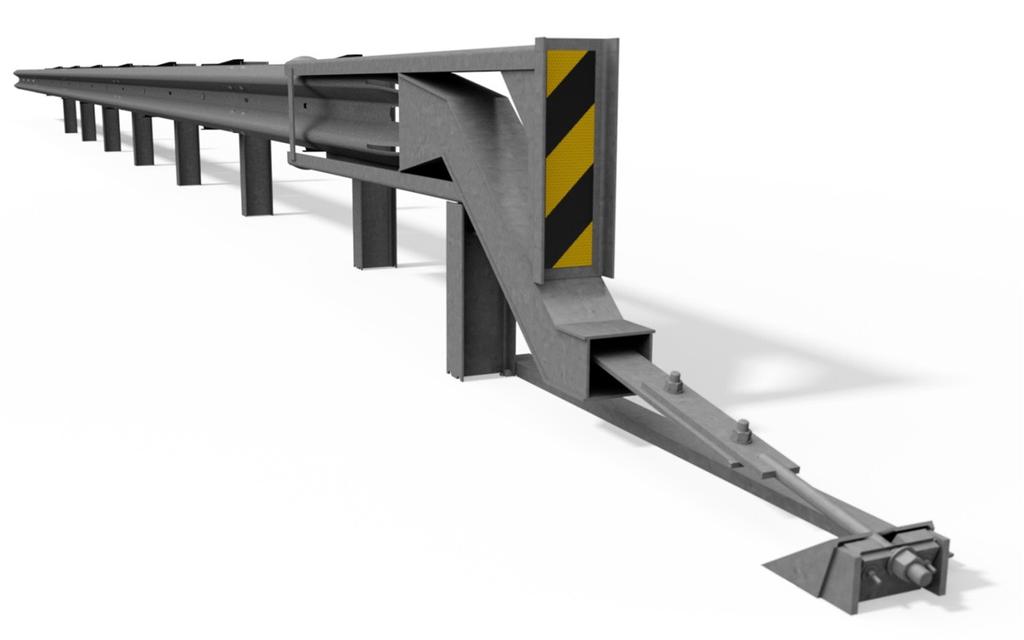
7 SoftStop System Overview The SoftStop System is a tangent, single-sided, energy-absorbing, redirective and gating end terminal system. The SoftStop System is the first end terminal to meet the evaluation criteria set forth in the AASHTO MASH. The SoftStop System is a 787 mm high (measured from top of rail to finished grade) end terminal used to shield 787 mm high strong post w-beam guardrail. The SoftStop System may be used to terminate strong post W-beam guardrail measuring between 705 mm to 787 mm with state approved transition (see Appendix for example). The SoftStop System contains a SoftStop Impact Head, SoftStop Anchor Rail, SoftStop Anchor Post (Post 0), SoftStop Angle Strut, two (2) Steel Yielding Terminal Posts ( SYTP ) (Posts 1 & 2) and required hardware accessories. The remaining length of the system beyond Post 2 uses System Line Posts, Offset Blocks and System Rail. System Rail(s) Offset Block(s) SoftStop Anchor Rail SoftStop Impact Head SoftStop Anchor Paddle System Line Post(s) SYTP SoftStop Angle Strut *Test Level 3 Configuration with 3.81m Panel Option shown SoftStop Anchor Post (Post 0) 6
8 The SoftStop System can be assembled in a MASH Test Level 1, Test Level 2 or Test Level 3 configuration. Test Level Design Speed Required System Length Posts Test Level km/h m Posts 0-8 Test Level 2 70 km/h m Posts 0-6 Test Level 1 50 km/h 7.86 m Posts 0-4 Test Level m Post 4 Post 6 Post 8 Post 3 Post 5 Post 7 Post 2 Post 4 Post 6 Test Level m Test Level m Post 1 Post 3 Post 5 Post 0 Post 2 Post 4 Post 1 Post 3 Post 0 Post 2 Post 1 Post All rights in copyright reserved
9 Inspect Shipment Before assembling the SoftStop System, carefully unpack and inspect all components for signs of damage. Check the received parts against the packing list supplied with the system to verify that all parts were received. If parts are damaged or missing from the shipment or unspecified parts were part of the shipment, do not attempt to assemble the system; contact Trinity Highway immediately. ID COMPONENT PN TL-3 QTY TL-2 QTY TL-1 QTY A SoftStop Impact Head 15208A B SoftStop Anchor Rail m 15200G C System Rail m 11G D SoftStop Anchor Post (Post 0) 15205A E SoftStop SYTP 1460 mm 15203G F SYTP Post 1830 mm 15000G G System Line Post 1830 mm 533G H Offset Block 6777B I SoftStop Anchor Paddle 15204A K SoftStop Keeper Plate 15207G L SoftStop Plate Washer 15206G M SoftStop Anchor Angle 15201G N SoftStop Angle Strut 15202G O 5/16 x 2.5 Hex Bolt G P 5/16 x 1.5 Hex Bolt G Q 3/4" x 2.5 Hex Bolt 3717G R 5/8 x 9 Hex Bolt 4489G S 5/8 x 1.75 Hex Bolt 3391G T 5/8 x 10 GR Bolt 3500G U 5/8 x 1.25 GR Bolt 3360G V 1 Round Washer 4902G W 3/4 Round Washer 3701G X 5/8 Round Washer 4372G Y 5/16 Round Washer Wide 3240G Z 1 Heavy Hex Nut 3908G AA 3/4 Heavy Hex Nut 3704G BB 5/8 GR Hex Nut 3340G CC 5/16 Hex Nut 3245G
 SoftStop Impact Head SoftStop Anchor Rail 3.")


10 ID: A PN: 15208A ID: B PN: 15200G ID: C PN: 11G (Slotted End Shown For Detail) SoftStop Impact Head SoftStop Anchor Rail m System Rail m ID: D PN: 15205A ID: E PN: 15203G ID: F PN: 15000G Post 0 Post 1 Post 2 SoftStop Anchor Post SoftStop SYTP 1460 mm SYTP 1830 mm Post ID: G PN: 533G ID: H PN: 6777B ID: I PN: 15204A Posts 3-8 System Line Post 1830 mm Offset Block SoftStop Anchor Paddle ID: K PN: 15207G ID: L PN: 15206G ID: M PN: 15201G SoftStop Keeper Plate SoftStop Plate Washer SoftStop Anchor Angle 9


11 ID: N PN: 15202G ID: O PN: G ID: P PN: G SoftStop Angle Strut 5/16 x 2.5 Hex Bolt 5/16 x 1.5 Hex Bolt ID: Q PN: 3717G ID: R PN: 4489G ID: S PN: 3391G 3/4 x 2.5 Hex Bolt 5/8 x 9 Hex Bolt 5/8 x 1.75 Hex Bolt ID: T PN: 3500G ID: U PN: 3360G ID: V PN: 4902G 5/8 x 10 GR Bolt 5/8 x 1.25 GR Bolt 1 Round Washer ID: W PN: 3701G ID: X PN: 4372G ID: Y PN: 3240G 3/4 Round Washer 5/8 Round Washer 5/16 Round Washer Wide 10


12 ID: Z PN: 3908G ID: AA PN: 3704G ID: BB PN: 3340G 1 Heavy Hex Nut 3/4" Heavy Hex Nut 5/8 GR Hex Nut ID: CC PN: 3245G 5/16 Hex Nut 11
13 Recommended Tools Documentation Assembly Manual (Most Current Version) System Drawing (Most Current Version) Personal protective equipment (PPE) Safety Glasses Work Gloves Safety-Toe Shoes Back Protection Hard Hat Reflective Vest Miscellaneous Traffic Control Equipment SAE Combination Wrench Set Socket Set & Socket Wrench Hammer Chalk Line Tape Measure Marking Paint and Pen Straight Edge Level Plumb Line Post Pounder (commonly used for driving posts) Auger Soil Tamper Come-Along Puller 5/8 Alignment Tool (Drift Pin) Cutting Device Locking Pliers C-Clamps Note: The above list of tools is a general recommendation only and should not be considered an exhaustive list. Depending on specific site conditions and the complexity of the assembly (or repair) specified by the appropriate highway authority, additional or fewer tools may be required. Decisions as to what tools are needed to perform the job are entirely within the discretion of the specifying highway authority and the authority s selected contractor performing the assembly of the system at the authority s specified site. 12
14 SoftStop System Site Preparation The SoftStop System is a tangent, single-sided, energy-absorbing, redirective and gating end terminal system that state/specifying agency specify for use as specified by the appropriate state/specifying authority in conjunction with strong post W-beam guardrail on the shoulder or median of a roadway. The decision to specify the SoftStop System for a particular project is the responsibility of the state/specifying agency design engineer who must ensure that the most appropriate end terminal has been selected for the specific site conditions. Important: Do not attach the SoftStop System directly to a rigid barrier (i.e. concrete barrier, wall or bridge pier) without the use of a state/specifying agency approved transition. Important: Ensure that the SoftStop System assembly conforms to the local road design standards. Important: Ingal Civil Products does not direct grading. Proper site grading must be accomplished before assembly of the SoftStop System in accordance with local specifying agency guidelines and the NZTA requirements. Failure to follow this warning could result in serious injury or death in the event of a vehicle impact or collision. 13
15 Drawing Source: AASHTO Roadside Design Guide, 4 th Edition
16 SoftStop System Offset Requirements The SoftStop System is a tangent guardrail end treatment that is assembled parallel to the edge of shoulder. At the sole discretion of the state/specifying agency design engineer, the SoftStop System may be offset away from the shoulder over the length of the entire system (from center of last splice location of SoftStop System to center of Post 0) per the following designer approved offsets: Test Level 1 (TL-1) Test Level 2 (TL-2) Test Level 3 (TL-3) 152 mm Maximum 304 mm Maximum 609 mm Maximum Caution: Under no circumstances shall the rail within the SoftStop System be curved. Offset Requirements Within A Curve When the guardrail is terminated within a curve (convex or concave) and a SoftStop System is attached, the following instructions must be followed to ensure proper offset requirements within a curve for the SoftStop System are met. If the conditions below cannot be achieved, it is recommended that the guardrail be extended past the curve until the conditions can be met. The offset requirements in a curve are calculated for the TL-3 SoftStop System. If assembling a TL-1 or TL-2 SoftStop System, an overall straight length of m must be obtained (SoftStop System + Strong Post W-Beam Guardrail) for calculating offset requirements in a curve. Note: Using an offset closer to 0 m on tighter curves (radii) will cause the terminal to encroach onto the shoulder. 15
17 Convex Curve For radii of 198 m or greater (flatter), the offset is 0 m to 609 mm. SoftStop System (TL-3) Strong Post W-Beam Convex Curve Direction of Traffic Concave Curve For radii between 152 m and 228 m, the offset is 0 m to 457 mm. For radii greater (flatter) than 228 m, the offset is 0 m to 609 mm. SoftStop System (TL-3) Strong Post W-Beam Offset Direction of Traffic Curve 16
18 SoftStop System Post Placement Determine Post Locations Danger: Ensure all above & below ground utilities are located, marked, and identified prior to using auger or post driving equipment in accordance with local specifying agency guidelines. Failure to follow this warning could result in serious injury or death. Place a level or straight edge on the face of downstream guardrail (i.e. traffic side) to the finished grade to create a reference line for face of guardrail. The reference line will be used to determine post location for the last post of the SoftStop System. The last post of the SoftStop System will be located 422 mm from face of downstream guardrail to back of the last post of the SoftStop System to accommodate an 190mm offset block and be spaced 1905 mm (typical) on center from the first post of the strong post w-beam system (see drawing below). Refer to the post placement diagrams in this manual for remaining post locations. 17
19 The SoftStop System posts may be inserted into the soil using an auger or post pounding equipment used for the placement of guardrail posts. If an auger is used, ensure diameter is large enough to allow for proper compaction of state/specifying agency approved fill material. All SoftStop System posts are to be assembled plumb. Proper compaction must be accomplished for all posts in accordance with state/specifying agency guidelines. If rock is encountered at post locations 2-8, refer to the local specifying agency guidelines and the AASHTO Roadside Design Guide for requirements for embedment depth into the rock and size of the hole. If rock is encountered at post locations 0-1, auger a hole in the rock large enough for full post embedment and proper compaction of approved fill material. If rigid pavement (e.g. concrete or asphalt) of any thickness is encountered at post locations 0-8, ensure a proper leave-out area (the specified size of open space as defined in the AASHTO Roadside Design Guide) is provided around the posts and filled with state/specifying agency approved backfill material. Steel Post Detail Section A-A *Grout fill material must have a 28-day compressive strength of 120 psi (0.85 MPa) or less. Drawing Source: AASHTO Roadside Design Guide, 4 th Edition
20 SoftStop System (Test Level 3) - Post Placement Diagram NOTES: 1. Post 0-8 part of SoftStop System TL3 (15.48m system length) 2. Post 7 9 & is 8 first are post not of required longitudinal for the w-beam TL2 system (11.67m (not included system with length) SoftStop System) Post Spacing 9 is between first post posts of longitudinal is centre w-beam as shown system (not included with SoftStop System) Spacing All SoftStop between System post posts 8 & 9 must is shown be installed 1905mm plumb on centre All Guardrail SoftStop splice System joint located posts must at Post be 9 installed plumb 5. Guardrail splice joint located at Post
21 SoftStop System Anchor Post (Post 0) Placement The SoftStop System Anchor Post (15205A) is the first post of the SoftStop System and is designated as Post 0. The SoftStop System Anchor Post is to be assembled plumb and oriented with the front side of post facing towards the upstream end. A. When assembled to the correct depth, the SoftStop System Anchor Post stub will protrude 89 mm above the finished grade line (see Step 2 of this Assembly Manual). B. When fully assembled, the SoftStop System Anchor Post (with Anchor Angles) will protrude 102 mm above the finished grade line (see Step 12 of this Assembly Manual). A. Anchor Post Stub at Correct Height Anchor Post - Front Side B. Anchor Post (Fully Assembled) at Correct Height Caution: Ensure the SoftStop System Anchor Post is assembled in the orientation shown above. Failure to follow this warning could result in serious injury or death in the event of a vehicle impact or collision with the system. 20

22 SoftStop System Impact Head The SoftStop Impact Head (15208A) component is symmetrical and can be assembled on the left or right shoulder. The diagram below lists some of the subcomponents of the Impact Head. Top Guide Channel Strike Plate Vertical Strap Bottom Guide Channel Connection Bracket Chute When properly assembled, the SoftStop Impact Head shall only be assembled parallel to the finished grade line or have an upward tilt (towards front of the system). The elevation of the Impact Head can vary a maximum of 58 mm higher at Point A relative to Point B. Point A is measured from the finished grade line to where the corner of the side plate connects with the top guide channel and Point B is measured from the finished grade line to where the inside corner of the vertical strap connects with the top guide channel. 21
23 TEST LEVEL 3 ASSEMBLY STEPS Important: Always use safety precautions when performing assembly, maintenance, repair and/or moving heaving equipment. Ensure proper personal protective equipment (PPE) is worn. Failure to follow this warning could result in serious injury or death. 22

24 STEP 1 System Line Post Assembly (Posts 3-8) Refer transition drawing SS-STD-002 Last Post of SoftStop System Post 8 PARTS INSTRUCTIONS G 533G 6 EA 1. Assemble all parts in the configuration & orientation as shown in the above diagram. 2. The SoftStop System must be attached to strong post w-beam guardrail that has been properly transitioned to 787 mm rail height per state/specifying agency (see Appendix for transition drawing example). 3. Establish the location of the last post of the SoftStop System (Post 8) by placing a level on the face of downstream guardrail to the finished grade and applying offset and post spacing requirements shown above. 4. Ensure proper post spacing and post height is achieved for Posts 3-8 (Part G) per shown dimensions above. Use only Trinity Highway parts that are specified herein for the SoftStop System for assembling, maintaining, or repairing the SoftStop System. Do not utilize or otherwise comingle parts from other systems even if those systems are Trinity Highway systems. WARNINGS Proper site grading must be accomplished in accordance with local specifying agency guidelines. Failure to follow this warning could result in serious injury or death in the event of a vehicle impact or collision with the system. 23
25 STEP 2 Post Assembly (Posts 0-2) PARTS INSTRUCTIONS F 15000G 1 EA 1. Assemble all parts in the configuration & orientation shown above. E 15203G 1 EA 2. Ensure proper offset for Post 0 (Part D) & Post 1 (Part E) is obtained per shown dimension above (offset measured from back of Post 2 (Part F) to D 15205A 1 EA center of Post 0 & Ensure center of yielding holes for Post 1 & 2 are approximately at finished grade, as shown. 4. Ensure Post 0 stub height does not exceed 89 mm above finished grade. 5. Ensure proper post spacing and post height is achieved per shown dimensions above. Use only Trinity Highway parts that are specified herein for the SoftStop System for assembling, maintaining, or repairing the SoftStop System. Do not utilize or otherwise comingle parts from other systems even if those systems are Trinity Highway systems. WARNINGS Proper site grading must be accomplished in accordance with local specifying agency guidelines. Failure to follow this warning could result in serious injury or death in the event of a vehicle impact or collision with the system. 24
26 STEP 3 Offset Block Assembly (Posts 3-8) PARTS INSTRUCTIONS H 6777B 6 EA 1. Assemble all parts in the configuration & orientation shown above. 2. Attach (1 EA) Offset Block (Part H) on traffic side of Posts 3-8. The Offset Block is equipped with a self-hanging mounting tab. Use only Trinity Highway parts that are specified herein for the SoftStop System for assembling, maintaining, or repairing the SoftStop System. Do not utilize or otherwise comingle parts from other systems even if those systems are Trinity Highway systems. WARNINGS Do not use any Offset Block (Part H) if they show signs of damage. Seek replacement from Ingal Civil Products prior to assembly. 25
 Offset Block (Part H) on traffic side of Post 2. The Offset Block is equipped with a self-hanging mounting tab. BB 3340G 1 EA 3. Secure Offset Block to post with shown hardware. 4.")
27 STEP 4 Offset Block Assembly (Post 2) PARTS INSTRUCTIONS H 6777B 1 EA 1. Assemble all parts in the configuration & orientation shown above. T 3500G 1 EA 2. Attach (1 EA) Offset Block (Part H) on traffic side of Post 2. The Offset Block is equipped with a self-hanging mounting tab. BB 3340G 1 EA 3. Secure Offset Block to post with shown hardware. 4. Tighten all threaded hardware to a snug position with an appropriately sized wrench or socket. Use only Trinity Highway parts that are specified herein for the SoftStop System for assembling, maintaining, or repairing the SoftStop System. Do not utilize or otherwise comingle parts from other systems even if those systems are Trinity Highway systems. WARNINGS Do not use any Offset Block (Part H) if they show signs of damage. See replacement from Ingal Civil Products prior to assembly. 26
28 STEP m System Rail Assembly (Post 3-8) Post 8 Post 3 PARTS INSTRUCTIONS C 11G 3 EA 1. Assemble all parts in the configuration & orientation shown above. T 3500G 6 EA 2. Place all System Rail panels (Part C) on the traffic side of the posts and lap all System Rail panels in the direction of traffic as shown above using U 3360G 24 EA shown hardware. BB 3340G 30 EA 3. Tighten all threaded hardware to a snug position with an appropriately sized wrench or socket. Use only Trinity Highway parts that are specified herein for the SoftStop System for assembling, maintaining, or repairing the SoftStop System. Do not utilize or otherwise comingle parts from other systems even if those systems are Trinity Highway systems. WARNINGS Do not place anything between any post bolt head and the SoftStop System Rail that would prevent the bolt from pulling through (i.e. no rectangular washers or delineators). Failure to follow this warning could result in serious injury or death in the event of a collision. 27
29 STEP 6 Anchor Rail Shipping Tabs Removal PARTS INSTRUCTIONS B 15200G 1 EA 1. The SoftStop Anchor Rail is manufactured with three (3) shipping tabs. EE 15215G 1 EA These shipping tabs shall be removed with a cutting device to assist in the assembly process. Note: Only one (1) SoftStop Anchor Rail is used per assembly. Use only Trinity Highway parts that are specified herein for the SoftStop System for assembling, maintaining, or repairing the SoftStop System. Do not utilize or otherwise comingle parts from other systems even if those systems are Trinity Highway systems. WARNINGS Keep body parts clear of cutting device. Ensure proper personal protective equipment (PPE) is worn. Failure to follow this warning could result in serious injury or death. 28
30 STEP 7 Anchor Rail Hardware Assembly SoftStop Anchor Rail (4 Plies) PARTS INSTRUCTIONS B Q W AA EE 15200G 3717G 3701G 3704G 15215G 1 EA 2 EA 4 EA 2 EA 1 EA 1. Assemble all parts in the configuration & orientation shown above. 2. Insert both hex bolts (Part Q) through the bottom side of the four (4) plies of the SoftStop Anchor Rail (Part B or Part EE). The bottom side is determined by the final assembled position on the SoftStop System. The use of locking pliers or c-clamps will aid the assembly process. 3. Tighten all threaded hardware to a snug position with an appropriately sized wrench or socket. Note: Only one (1) SoftStop Anchor Rail is used per assembly. Use only Trinity Highway parts that are specified herein for the SoftStop System for assembling, maintaining, or repairing the SoftStop System. Do not utilize or otherwise comingle parts from other systems even if those systems are Trinity Highway systems. WARNINGS Insert the SoftStop Anchor Paddle Bolts (Part Q) from the bottom of the SoftStop Anchor Rail. Failure to follow this warning could result in serious injury or death in the event of a collision. 29
31 STEP 8 Anchor Rail Assembly Post 2 PARTS INSTRUCTIONS B 15200G 1 EA 1. Assemble all parts in the configuration & orientation shown above. U 3360G 8 EA 2. Place SoftStop Anchor Rail (Part B) on the traffic side and lap in the direction of traffic as shown above using shown hardware. BB 3340G 8 EA 3. Tighten all threaded hardware to a snug position with an appropriately sized wrench or socket. Use only Trinity Highway parts that are specified herein for the SoftStop System for assembling, maintaining, or repairing the SoftStop System. Do not utilize or otherwise comingle parts from other systems even if those systems are Trinity Highway systems. WARNINGS Do not bolt the SoftStop Anchor Rail to Post 2. Failure to follow this warning could result in serious injury or death in the event of a collision. 30
32 STEP 9 Impact Head Assembly Connection Bracket Detail Post 1 PARTS INSTRUCTIONS A 15208A 1 EA 1. Assemble all parts in the configuration & orientation shown above. P G 1 EA 2. Mechanically push the SoftStop Impact Head (Part A) until its Connection Bracket rests against Post 1 and a minimum 457 mm of the Y 3240G 2 EA SoftStop Anchor Rail is protruding out the Chute. CC 3245G 1 EA 3. Fasten Post 1 and the Connection Bracket together with shown hardware (Parts P, Y, & CC). See Connection Bracket detail. 4. Tighten all threaded hardware to a snug position with an appropriately sized wrench or socket. Use only Trinity Highway parts that are specified herein for the SoftStop System for assembling, maintaining, or repairing the SoftStop System. Do not utilize or otherwise comingle parts from other systems even if those systems are Trinity Highway systems. WARNINGS The SoftStop Impact Head Connection Bracket must rest against the front side of Post #1 (between Posts 0-1) as shown in the Connection Bracket Detail above. 31
33 STEP 10 Anchor Paddle Assembly Protruding SoftStop Anchor Rail (4 Plies) PARTS INSTRUCTIONS I 15204A 1 EA 1. Assemble all parts in the configuration & orientation shown above. 2. Remove the nuts (Part AA) and top washers (Part W) and place the W 3701G 2 EA SoftStop Anchor Paddle (Part I) onto the hex bolts. The SoftStop Anchor AA 3704G 2 EA Paddle is assembled on the top side of the four (4) plies of the protruding SoftStop Anchor Rail. Reassemble the top washers and nuts onto the hex bolt as shown above. The use of locking pliers or c-clamps will aid the assembly process. 3. Tighten all threaded hardware to a snug position with an appropriately sized wrench or socket. Use only Trinity Highway parts that are specified herein for the SoftStop System for assembling, maintaining, or repairing the SoftStop System. Do not utilize or otherwise comingle parts from other systems even if those systems are Trinity Highway systems. WARNINGS The SoftStop Anchor Paddle (Part I) must be placed on the topside of the SoftStop Anchor Rail. Failure to follow this warning could result in serious injury or death in the event of a collision. 32
34 STEP 11 Anchor Post Assembly (Post 0) Before Post 0 After SoftStop Anchor Paddle Rod PARTS INSTRUCTIONS Y 3240G 4 EA 1. Assemble all parts in the configuration & orientation shown above. CC 3245G 2 EA 2. Place the rod portion of the SoftStop Anchor Paddle in the notch of Post 0. Z 3908G 1 EA 3. Place the SoftStop Keeper Plate (Part K) and SoftStop Plate Washer V 4902G 1 EA (Part L) onto the SoftStop Anchor Paddle Rod and fasten to Post 0 using shown hardware (Part O, Y, CC). L 15206G 1 EA 4. Place washer (Part V) then nut (Part Z) on the SoftStop Anchor Paddle K 15207G 1 EA Rod. 5. Tighten all threaded hardware to a snug position with an appropriately O G 2 EA sized wrench or socket. Use only Trinity Highway parts that are specified herein for the SoftStop System for assembling, maintaining, or repairing the SoftStop System. Do not utilize or otherwise comingle parts from other systems even if those systems are Trinity Highway systems. WARNINGS Ensure the 1 Hex Nut (Part Z) has been fully tightened against the SoftStop Plate Washer (Part L). Failure to follow this warning could result in serious injury or death in the event of a collision. 33
35 STEP 12 Angle Strut Assembly (Posts 0-1) Post 1 Post 0 Anchor Angle (2 EA) Note: Items below grade shown for clarity. PARTS INSTRUCTIONS BB 3340G 2 EA 1. Assemble all parts in the configuration & orientation shown above. X 4372G 4 EA 2. It will be necessary to make a shallow valley/trough between Post 0 & 1 for the SoftStop Angle Strut (Part N) and SoftStop Anchor R 4489G 1 EA Angles (Part M), since a portion will be below the finished grade. M 15201G 2 EA 3. Position the SoftStop Anchor Angles (Part M) onto Post 0 and place SoftStop Angle Strut on the non-traffic side with short leg down and fasten N 15202G 1 EA to Post 0 & 1 using shown hardware (Part R, S, X, BB). S 3391G 1 EA 4. Tighten all threaded hardware to a snug position with an appropriately sized wrench or socket. Use only Trinity Highway parts that are specified herein for the SoftStop System for assembling, maintaining, or repairing the SoftStop System. Do not utilize or otherwise comingle parts from other systems even if those systems are Trinity Highway systems. WARNINGS Ensure fully assembled SoftStop Anchor Post height (with SoftStop Anchor Angles) does not exceed 102 mm above finished grade line. 34
36 STEP 13 Delineation Assembly PARTS By Others INSTRUCTIONS 1. Assemble all parts in the configuration & orientation shown above. Note: Manufacturer suggests that user provide delineation (reflective sheeting) of the terminal. Use only Trinity Highway parts that are specified herein for the SoftStop System for assembling, maintaining, or repairing the SoftStop System. Do not utilize or otherwise comingle parts from other systems even if those systems are Trinity Highway systems. WARNINGS Ensure delineation (reflective sheeting) used on SoftStop System meets state/specifying agency s MUTCD for proper delineation. Use of steel delineator posts are not permitted within 3-0 of the SoftStop System. 35
 Yes No Is Anchor Keeper Plate installed in correct configuration on Anchor post (Detail A on drawing")
37 SoftStop Guardrail End Terminal SoftStop Installation Checklist Customer: Project: Barrier ID: Terminal Type: MASH TL2 MASH TL3 Checked By: Signed: Date: Is the assembled Anchor post installed in the correct orientation with the sloped side facing the terminal and within tolerance (102 +0/-6 mm) Yes No Is Anchor Keeper Plate installed in correct configuration on Anchor post (Detail A on drawing SS-STD-001 Yes No Have Anchor post Angles been correctly bolted to the Anchor post (Detail A on drawing SS-STD-001) Yes No Is the Ground Strut bolted to the Anchor post and post 1 (Detail B on drawing SSSTD-001) Yes No The SoftStop head is bolted to post 1 (as per Detail D on drawing SS-STD-001) Yes No Are SYT posts positioned at locations 1 & 2, with yield holes approximately centred at finished grade line Yes No Are posts 2 through 8 at the correct height of 813mm ±20mm above ground level Yes No Are the rails secured to posts 3 through 8 (posts 3 and 4 for the TL2 configuration) Yes No Ensure first rail is NOT secured to post at location 2 Yes No Have the rails been joined with M16x32mm splice head bolts Yes No Are all splice bolts, post bolts and other fasteners snug tight Yes No Do the standard W-Beam rails form a smooth line vertically and horizontally when viewed along the system, with no curved rails Yes No Is all back-filled material around each post suitably compacted Yes No Is the area below the guardrails free from hazards so that the SoftStop head can travel freely upon impact Yes No Ensure any minor damage been repaired using two coats of an organic zinc rich paint Yes No When installed on a flare, ensure flare rate is no greater than 1:25 (610mm offset from straight barrier over full length for TL3 configuration, 305mm for TL2 configuration) Yes No Ensure SoftStop impact head has no more than 58mm of upward tilt, measured over length of impact head (refer Note 5 on drawing SS-STD-001) Yes No Release 08/16
38 Appendix Offsite Anchor Rail Pre-Assembly Method Step A: The SoftStop Anchor Rail is manufactured with three (3) shipping tabs. These shipping tabs shall be removed with a cutting device to assist in the assembly process. The SoftStop Anchor Rail is available in two lengths: 12-6 (Part B) or 25-0 (Part EE). Note: Only one (1) SoftStop Anchor Rail is used per assembly, 12-6 (Part B) or 25-0 (Part EE). Warning: Keep body parts clear of cutting device. Ensure proper personal protective equipment (PPE) is worn. Failure to follow this warning could result in serious injury or death. 37
39 Step B: Assemble all parts in the configuration & orientation shown below. Flatten the (4) plies of the SoftStop Anchor Rail together and insert both hex bolts (Part Q) through the bottom side of the four (4) plies of the SoftStop Anchor Rail (Part B or Part EE) with washers and nuts (Parts W & AA). The bottom side is determined by the final assembled position of the SoftStop System (nuts are on top side of Anchor Rail). The use of locking pliers or c-clamps will assist the assembly process. Step C: Feed the flattened slotted end of the SoftStop Anchor Rail (Part B or Part EE) into the SoftStop Impact Head (Part A) until a minimum 18 [457 mm] of the SoftStop Anchor Rail is protruding out the Chute of the SoftStop Impact Head. This can be achieved by the use of a come-a-long or other mechanical means. 38
40 NOTES: 1. Post 0-6 part of SoftStop System TL2 2. Post 7 is first post of longitudinal w-beam system (not included with SoftStop System) 3. Spacing between posts is on centre as shown 4. All SoftStop System posts must be installed plumb 5. Guardrail splice joint located at Post 7 SoftStop System (Test Level 2) - Post Placement Diagram
41 NOTES: 1. Post 0-4 part of SoftStop System TL1 2. Post 5 is first post of longitudinal w-beam system (not included with SoftStop System) 3. Spacing between posts is on centre as shown 4. All SoftStop System posts must be installed plumb 5. Guardrail splice joint located at Post 5 SoftStop System (Test Level 1) - Post Placement Diagram
42 SoftStop System (Test Level 1) - Post Placement Diagram 41
43 42
44 Notes 43
45 Notes 44
46 For more complete information on Ingal Civil Products' products and services, visit us on the web at Materials and specifications are subject to change without notice. Please contact Ingal Civil Products to confirm that you are referring to the most current instructions
T-39 Thriebeam. Product Manual. NCHRP 350 Test Level 3 & 4 Compliant Barrier. Release 01/11
 T-39 Thriebeam NCHRP 350 Test Level 3 & 4 Compliant Barrier Product Manual T-39 is licensed to Ingal Civil Products by Trinity Industries Inc. of the U.S.A. www.ingalcivil.com.au T-39 Thriebeam NCHRP 350
Installation Manual. Orion. TL-3 Steel Barrier. VHD (v2)
") Installation Manual Orion TL-3 Steel Barrier VHD (v2) 300914 Table of Contents Orion Introduction.......... 3 Limitations & Warnings. 4 Before Installation..... 3 System Design & Design Considerations
Installation Manual Orion TL-3 Steel Barrier VHD (v2) 300914 Table of Contents Orion Introduction.......... 3 Limitations & Warnings. 4 Before Installation..... 3 System Design & Design Considerations
RAMSHIELD. New Zealand Edition. Product & Installation Manual. MASH TL3 Compliant W-Beam Barrier. Ref: PM 023/0
 RAMSHIELD MASH TL3 Compliant W-Beam Barrier Product & Installation Manual New Zealand Edition Ref: PM 023/0 Table of Contents 1.0 Introduction... 5 2.0 Specifications... 5 3.0 How RAMSHIELD Works... 6
Product Manual Release 05/17
 Temporary Safety Barrier (TL-2 MASH) Product Manual VHD (v3) www.valmonthighway.com Table of Contents 1.0 ArmorZone Introduction... 3 2.0 Before Installation... 3 3.0 Limitations & Warnings... 3 4.0 System
Nu-Guard 31. Roadside and Median Guardrail System. MASH TL-3 & NCHRP TL-4 Product & Installation Manual
 Nu-Guard 31 Roadside and Median Guardrail System MASH TL-3 & NCHRP TL-4 Product & Installation Manual Ph 0800 655 200 or visit www.csppacific.co.nz April 15 / Page 1 Table of Contents NU-GUARD 31 Introduction......
Technical Memorandum: Road Safety Hardware Series. technical memorandum
 technical memorandum road safety hardware series Frequently Asked Questions - Barriers & Terminals TM-2000 October 2012 Purpose To provide a list of frequently asked questions with answers in regard to
QuadGuard II. Assembly Manual Stemmons Freeway Dallas, Texas 75207
 QuadGuard II Assembly Manual 2525 Stemmons Freeway Dallas, Texas 75207 Important: These instructions are to be used only in conjunction with the assembly, maintenance, and repair of QuadGuard II systems.
Flexbeam Guardrail Roadside Safety Barrier
 Flexbeam Guardrail Roadside Safety Barrier Product Manual Release 09/15 www.ingalcivil.com.au Flexbeam Guardrail Roadside Safety Barrier 1.0 Introduction Roadside barriers have been developed over the
TRACC. Product Manual. Crash attenuation cushion. Release 10/14
 TRACC Crash attenuation cushion Product Manual Release 10/14 TRACC is licensed to Ingal Civil Products by Trinity Industries Inc. of the U.S.A. www.ingalcivil.com.au TRACC Crash attenuation cushion 1.0
DESIGN GUIDE. Advancing Safety Through Innovation. TCC-DG01 07/18/02 Page 1
 DESIGN GUIDE Advancing Safety Through Innovation Patents Pending Copyright 2002 BSI TCC-DG01 07/18/02 Page 1 TAU-II Crash Cushion DESIGN Table of Contents Preface 22 Introduction 2 Important Information..
ArmorZone TL-2 Barrier and End Treatment
 ArmorZone TL-2 Barrier and End Treatment Product and Installation Manual ANOTHER AMORFLEX DEVELOPMENT Table of contents Introduction 3 System Overview 3 Before Installation 3 Limitations and Warnings 4
TRACC. Crash Attenuation Cushion. Product Manual
 TRACC Crash Attenuation Cushion Product Manual Release 07/15 TRACC is licensed to Ingal Civil Products by Trinity Industries Inc. of the U.S.A. www.ingalcivil.com.au TRACC Crash Attenuation Cushion 1.0
ArmorZone TL-2 Barrier
 ArmorZone TL-2 Barrier Product Manual ANOTHER AMORFLEX DEVELOPMENT Table of contents Introduction 3 System overview 3 Before installation 3 Limitations and warnings 4 Safety statements 4 System design
TRACC. Crash Attenuation Cushion. Product Manual
 TRACC Crash Attenuation Cushion Product Manual Release 08/16 TRACC is licensed to Ingal Civil Products by Trinity Industries Inc. of the U.S.A. www.ingalcivil.com.au TRACC Crash Attenuation Cushion 1.0
TRAFFIC DIRECTION FOR RAIL LAP AS SHOWN (SEE NOTE 7) "SPLICE BOLT" WITH NUT MIDWEST GUARDRAIL SYSTEM (STANDARD AND REDUCED POST SPACING)
 SPLICE BOLT WITH NUT MIDWEST GUARDRAIL SYSTEM (STANDARD AND REDUCED POST SPACING)") TRAFFIC DIRECTION FOR RAIL LAP AS SHOWN GR-MGS1, 1A (SEE NOTE 7) NOTES: 1. 2. 3. 4. 5. 6. 236 6'-3" 6'-3" 3'-1 " 3'-1 " 3'-1 " 3'-1 " GR-MGS1 (6'-3" POST SPACING) SPLICE DETAIL W-BEAM RAIL SPLICE MID-SPAN
TRAFFIC DIRECTION FOR RAIL LAP AS SHOWN GR-MGS1, 1A (SEE NOTE 7) NOTES: 1. 2. 3. 4. 5. 6. 236 6'-3" 6'-3" 3'-1 " 3'-1 " 3'-1 " 3'-1 " GR-MGS1 (6'-3" POST SPACING) SPLICE DETAIL W-BEAM RAIL SPLICE MID-SPAN
Universal Armorwire Terminal End
 Installation Manual Universal Armorwire Terminal End Anchoring for 3 & 4 Cable Barriers VHD (v2) 300914 Table of Contents Universal A.T.E Introduction.. 3 Limitations and Warnings.... 3 Before Installation..
INSTALLATION MANUAL ORION BARRIER. NCHRP 350 TL-3 Portable Steel Longitudinal Barrier
 INSTALLATION MANUAL ORION BARRIER NCHRP 350 TL-3 Portable Steel Longitudinal Barrier INSTALLATION AND MAINTENANCE MANUAL Table of Contents Orion Introduction.......... 3 System Overview..... 3 Before Installation....
Installation and Repair Manual
 Trinity Attenuating Crash Cushion Installation and Repair Manual An NCHRP Report 350 Crash Cushion CSP Pacific Business Unit of Fletcher Concrete & Infrastructure Limited 306 Neilson Street Onehunga, Auckland
ArmorWire Cable Barrier
 Installation Manual ArmorWire Cable Barrier TL-3 & TL-4 Systems VHD (v2) 300914 Table of Contents ArmorWire Introduction......... 3 Limitations and Warnings... 3 Before Installation. 3 Design Considerations......
INGAL CIVIL PRODUCTS. Product Manual. Release 01/18.
 Product Manual www.ingalcivil.co.nz 1.0 Introduction 2.0 Specifications Introducing Ezy-Guard HC, a member of the Ezy-Guard family, the next generation steel guardrail barrier providing superior motorist
EuroTRACC. Product Description Assembly Manual
 EuroTRACC Product Description Assembly Manual Part No. 620078B EuroTRACC Product Description Assembly Manual Trinity Highway Products, LLC d.b.a. 2525 Stemmons Freeway Dallas, Texas 75207 Important: These
Installation Instructions/Operation and Maintenance Manual. Models PLG-60 PLG-72. PS DOORS Contact Information. Website psdoors.
 Rev. 091416 Pallet Gate Installation Instructions/Operation and Maintenance Manual Models PLG-60 PLG-72 Table of Contents Product Information...2 Installation Instructions...3 Operation...6 Inspection
CONSTRUCTION SPECIFICATION FOR ENERGY ATTENUATORS
 ONTARIO PROVINCIAL STANDARD SPECIFICATION METRIC OPSS 723 NOVEMBER 2011 CONSTRUCTION SPECIFICATION FOR ENERGY ATTENUATORS TABLE OF CONTENTS 723.01 SCOPE 723.02 REFERENCES 723.03 DEFINITIONS 723.04 DESIGN
QuadGuard System. General Specifications. CEN General Specifications
 QuadGuard System General Specifications CEN General Specifications QuadGuard System GENERAL SPECIFICATIONS I. GENERAL All QuadGuard Systems shall be designed and manufactured by Energy Absorption Systems,
TRACC-Family System Manual
 Trinity Attenuating Crash Cushion TRACC-Family System Manual A Family of NCHRP Report 350 Crash Cushions Trinity Industries, Inc. 2525 Stemmons Freeway Dallas, Texas 75207 U.S. Calls: (800)-644-7976 International
Leveling Foot RB210. Leg Extender RLT66
 Landing for Right & Left Turn R342 ITEMS # 0254049, 0254061, 0254072, 0254076, 0016567, 0254099, 0254110, 0054116, 0254117, 0254126, 0254140, 0254150, 0254156 CUSTOM ACCESS RAMP SYSTEM MODELS # R100, R242,
Curved W-beam rails shall be formed to the radius specified in accordance with drawing TEB 3.54.
 14.1 Guardrail - General Guardrail located at bridge approaches is a safety item designed to dampen the stray vehicle impact energy and then deflect it back onto the riding surface. To provide the degree
B STEEL BEAM GUIDE RAIL - OPSS 721
 B721-2 - - OPSS 721 721-2.1 GENERAL Design guidance and a description of Steel Beam Guide Rail systems, including various types and treatments, are provided in the Roadside Design Manual (RDM). 721-2.2
BarrierGuard 800 Gate
 Product and Installation Manual BarrierGuard 800 Gate NCHRP 350 TL-3 Australia & New Zealand Rev. A 06/17 2018 Highway Care Limited. All Rights Reserved. Page 1 of 23 Revision History Revision Date Prepared
STRUCTURAL STEEL FRAMING
 SECTION 05 12 00 - STRUCTURAL STEEL FRAMING PART 1 - GENERAL 1.1 SUMMARY A. Section includes 1. Structural steel framing 2. Structural steel framing required for support and framing of rooftop mechanical
TL-2 Plastic Water Filled Barrier
 TL-2 Plastic Water Filled Barrier Product Manual ANOTHER AMORFLEX DEVELOPMENT Table of contents Introduction 3 System overview 3 Before installation 3 Limitations and warnings 4 Safety statements 4 System
MDS TL5 Minimum Deflection Systems
 MDS Minimum Deflection Systems Approvals FHWA NCHRP 350 MASH EN1317 H4 MDS BARRIERS Bridge & Road STEEL BARRIER SYSTEMS Page Page 1 1 V11 MDS BARRIERS Run-off-road crashes are one of the most common types
ITEM 686 TRAFFIC SIGNAL POLE ASSEMBLIES (STEEL)
") ITEM 686 TRAFFIC SIGNAL POLE ASSEMBLIES (STEEL) 686.1. Description. This Item shall govern for designing, fabricating, furnishing and erecting steel traffic signal pole assemblies of the various types
ITEM 686 TRAFFIC SIGNAL POLE ASSEMBLIES (STEEL) 686.1. Description. This Item shall govern for designing, fabricating, furnishing and erecting steel traffic signal pole assemblies of the various types
To Contact PS DOORS:
 MODELS Stainless Steel (SS) Powder Coat Yellow (PCY) Hot Dipped Galvanized (GAL) TABLE OF CONTENTS PAGE Warranty Information General Paired LSG Information Installing the Support Channels 3 Installing
CONTRACT PROVISIONS. 1. The Contract will become effective beginning July 1, 2014 and will expire on July 1, 2015.
 CONTRACT PROVISIONS 1. The Contract will become effective beginning July 1, 2014 and will expire on July 1, 2015. 2. Guardrail repairs will be limited to Interstate and State Highways located in the Aberdeen
CONSTRUCTION SPECIFICATION FOR STEEL BEAM GUIDE RAIL AND CABLE GUIDE RAIL
 ONTARIO PROVINCIAL STANDARD SPECIFICATION METRIC OPSS.MUNI 721 NOVEMBER 2014 CONSTRUCTION SPECIFICATION FOR STEEL BEAM GUIDE RAIL AND CABLE GUIDE RAIL TABLE OF CONTENTS 721.01 SCOPE 721.02 REFERENCES 721.03
1. Base plates, setting plates and anchor rods for columns. 8. Lintels if connected to structural steel columns.
 PAGE 051200-1 SECTION 051200 PART 1 - GENERAL 1.1 RELATED DOCUMENTS A. Drawings and general provisions of the Contract, including General and Supplementary Conditions and Division 01 Specification sections,
Operator s Manual for Morse Mobile-Karrier for 55-Gallon Plastic or Steel Drum
 Contents Page Receiving Procedures.................... 1 Warranty............................. 1 Safety Information..................... 1-2 Machine Description................... 3 Operating Instructions....................
Product Specification ArmorGuard Barrier System
 TB 081030 Rev. 0 Page 1 of 6 Product Specification ArmorGuard Barrier System I. General The ArmorGuard Barrier System is a longitudinal barrier, as defined in the AASHTO Roadside Design Guide, which can
CONSTRUCTION SPECIFICATION FOR GUIDE RAIL END TREATMENT - STEEL BEAM ENERGY ATTENUATING TERMINAL SYSTEMS
 ONTARIO PROVINCIAL STANDARD SPECIFICATION METRIC OPSS.MUNI 732 APRIL 2017 CONSTRUCTION SPECIFICATION FOR GUIDE RAIL END TREATMENT - STEEL BEAM ENERGY ATTENUATING TERMINAL SYSTEMS TABLE OF CONTENTS 732.01
Model # 338SM-OP. 9/30/2011 Page 1 of 12
 Model # 338SM-OP 9/30/2011 Page 1 of 12 9/30/2011 Page 2 of 12 1675 Locust Street Red Bud, IL 62278 Phone: 618-282-8200 Fax: 618-282-8202 WARRANTY & TERMS WARRANTY: 5 Year Limited Warranty on Thermoplastic
GUIDERAILS INTRODUCTION DESIGN PURPOSE CHAPTER 12
 401 CHAPTER 12 GUIDERAILS INTRODUCTION The general intent of the highway engineer is to design a roadway in which the geometry creates a safe driving environment that does not require guiderail or median
Instructions for the use of the Link 4 Pallet Rack Lifter (PRL) model 5000
 model 5000") Instructions for the use of the Link 4 Pallet Rack Lifter (PRL) model 5000 (How to move your pallet racking using the Link 4 Pallet Rack Lifter) This process is for a typical rack move and reset. Each
Instructions for the use of the Link 4 Pallet Rack Lifter (PRL) model 5000 (How to move your pallet racking using the Link 4 Pallet Rack Lifter) This process is for a typical rack move and reset. Each
CITY OF FARGO SPECIFICATIONS SIGNING
 SECTION 4300 SIGNING PART 1 DESCRIPTION OF WORK The work to be done under this section of the Specifications and the accompanying plans consists of furnishing all labor, material and accessories necessary
Model # 362S-RDP. 9/17/2012 Page 1 of 12
 Model # 362S-RDP 9/17/2012 Page 1 of 12 9/17/2012 Page 2 of 12 1675 Locust Street Red Bud, IL 62278 Phone: 618-282-8200 Fax: 618-282-8202 WARRANTY & TERMS WARRANTY: 5 Year Limited Warranty on Thermoplastic
Product Manual. Release 04/15.
 Product Manual www.ezyguard.com 1.0 Introduction Introducing Ezy-Guard Smart, a member of the Ezy-Guard family, the next generation steel guardrail barrier providing superior motorist safety and more metres
H 12 Heavy Duty Modern Tripod 8 Seat Swing Heavy Duty Hangers
 Page 1 IMPORTANT Please retain this instruction sheet in your files. It contains important replacement parts information. All equipment should be installed in accordance with these instructions. It is
Model # 338S-PR. 5/1/2014 Page 1 of 12
 Model # 338S-PR 5/1/2014 Page 1 of 12 /1/2014 Page 2 of 12 1675 Locust Street Red Bud, IL 62278 Phone: 618-282-8200 Fax: 618-282-8202 WARRANTY & TERMS WARRANTY: 5 Year Limited Warranty on Thermoplastic
Product Manual REACT 350 (36") (3 foot [915 mm] wide Systems) Reusable Energy Absorbing Crash Terminal
![Product Manual REACT 350 (36) (3 foot [915 mm] wide Systems) Reusable Energy Absorbing Crash Terminal](/thumbs/76/73919372.jpg "Product Manual REACT 350 (36) (3 foot [915 mm] wide Systems) Reusable Energy Absorbing Crash Terminal") (3 foot [915 mm] wide Systems) Reusable Energy Absorbing Crash Terminal Self-Restoring, Reusable Crash Cushions for Narrow Hazards ENERGY ABSORPTION SYSTEMS, INC. A Quixote Company Saving Lives By Design
(3 foot [915 mm] wide Systems) Reusable Energy Absorbing Crash Terminal Self-Restoring, Reusable Crash Cushions for Narrow Hazards ENERGY ABSORPTION SYSTEMS, INC. A Quixote Company Saving Lives By Design
CITY OF FARGO SPECIFICATIONS SIGNING
 SIGNING PART 1 DESCRIPTION OF WORK The work to be done under this section of the Specifications and the accompanying plans consists of furnishing all labor, material and accessories necessary to complete
Universal Elevator Mount Owners Manual
 REQUIRED TOOLS AND MATERIALS: 2 Capable Adults Universal Elevator Mount Owners Manual 1-00-spalding Carpenter s Level 15 Tape Measure Pencil Adult Assembly Required. This manual, accompanied by sales receipt,
Installation Manual. ArchCast Bridge. 3-Sided Precast Concrete Bridge Structure
 ArchCast Bridge 3-Sided Precast Concrete Bridge Structure Installation Manual Salem Location: 749 West Commercial Ave. Salem, IL 62881 (618) 548-1190 countymaterials.com Email: info@countymaterials.com
KANSAS DEPARTMENT OF TRANSPORTATION SPECIAL PROVISION TO THE STANDARD SPECIFICATIONS, 1990 EDITION
 KANSAS DEPARTMENT OF TRANSPORTATION SPECIAL PROVISION TO THE STANDARD SPECIFICATIONS, 1990 EDITION Sheet 1 of 7 NOTE: This special provision is generally written in the imperative mood. The subject, the
Chapter 4 Bridge Program Drawings
 Chapter 4 Bridge Program Drawings Section 4.10-Bridge Railing Introduction Steel bridge railing and concrete bridge barrier rail are installed along the edge of the bridge roadway to keep errant vehicles
Model # 338S-P. 7/31/2012 Page 1 of 13
 Model # 338S-P 7/31/2012 Page 1 of 13 7/31/2012 Page 2 of 13 1675 Locust Street Red Bud, IL 62278 Phone: 618-282-8200 Fax: 618-282-8202 WARRANTY & TERMS WARRANTY: 5 Year Limited Warranty on Thermoplastic
Product Manual. QUEST CEN System. Redirective, Bidirectional Crash Cushion ENERGY ABSORPTION
 Redirective, Bidirectional Crash Cushion ENERGY ABSORPTION SYSTEMS, INC. A Quixote Company Saving Lives By Design Corporate Offices: 35 East Wacker Dr., 11th Floor Chicago, IL 60601-2076 Telephone: (312)
STP Mount Series. Installation Manual. STP-LSCR-MAN 2017 Edition v1.0. For models: STP-SCR/045 STP-SCR/060 STP-SCR/070 STP-LCR/090 STP-LCR/120
 Installation Manual STP-LSCR-MAN 2017 Edition v1.0 For models: STP-SCR/045 STP-SCR/060 STP-SCR/070 STP-LCR/090 STP-LCR/120 Table of Contents Introduction... 1 Customer Support... 1 Tools Required... 2
Model # 940S-P6-BB. 6/7/2017 Page 1 of 10
 Model # 940S-P6-BB 6/7/2017 Page 1 of 10 /7/2017 Page 2 of 10 1675 Locust Street Red Bud, IL 62278 Phone: 618-282-8200 Fax: 618-282-8202 WARRANTY & TERMS WARRANTY: 5 Year Limited Warranty on Thermoplastic
B STEEL BEAM GUIDE RAIL - OPSS 721
 B721-2 - - OPSS 721 721-2.1 GENERAL Steel Beam Guide Rail (SBGR) is a semi-rigid barrier system which restrains and redirects vehicles by a combination of beam bending (W-shaped steel section), tension,
Model # 338S-RDP. 7/31/2012 Page 1 of 13
 Model # 338S-RDP 7/31/2012 Page 1 of 13 7/31/2012 Page 2 of 13 1675 Locust Street Red Bud, IL 62278 Phone: 618-282-8200 Fax: 618-282-8202 WARRANTY & TERMS WARRANTY: 5 Year Limited Warranty on Thermoplastic
Model # 238HS-P8. 4/27/2011 Page 1 of 11
 Model # 238HS-P8 4/27/2011 Page 1 of 11 4/27/2011 Page 2 of 11 1675 Locust Street Red Bud, IL 62278 Phone: 618-282-8200 Fax: 618-282-8202 WARRANTY & TERMS WARRANTY: 5 Year Limited Warranty on Thermoplastic
GROUND MOUNT INSTALLATION MANUAL
 GROUND MOUNT INSTALLATION MANUAL Contents DISCLAIMER 1 CHECKLIST 2 1. ERECT BASe 3 2. CONNECT PIPES 3 3. PLACE RAILS 4 4. SECURE LUGS 4 5. CLAMP MODULES 5 DIAGONAL BRACES (OPTIONAL) 6 UNDER CLAMPS (OPTIONAL)
BarrierGuard 800 Gate
 BarrierGuard 800 Gate Product Manual Australia & New Zealand NCHRP 350 TL-3 Assembly, Installation & Operation Revision History Revision Date Prepared by Approved by Reason for change 1a 22 nd July 2015
MDS TL4 Minimum Deflection Systems
 MDS Approvals FHWA NCHRP 350 MASH-08 EN1317 H2 Bridge & Road STEEL BARRIER SYSTEMS Page 1 V11 Run-off-road crashes are one of the most common types of crashes in urban and highway environments. Installing
B STEEL BEAM GUIDE RAIL - OPSS.PROV 721
 B721-2 - - OPSS.PROV 721 721-2.1 GENERAL Steel beam guide rail (SBGR) is a semi-rigid barrier system which restrains and redirects vehicles by a combination of beam bending (W-shaped steel section), tension,
Model # BARK /26/2012 Page 1 of 5
 Model # BARK-430 6/26/2012 Page 1 of 5 6/26/2012 Page 2 of 5 1675 Locust Street Red Bud, IL 62278 Phone: 618-282-8200 Fax: 618-282-8202 WARRANTY & TERMS WARRANTY: 5 Year Limited Warranty on Thermoplastic/Canine
Product Manual. Release 08/17.
 Product Manual www.ezyguard.com 1.0 Introduction Introducing Ezy-Guard Smart, a member of the Ezy-Guard family, the next generation steel guardrail barrier providing superior motorist safety and more metres
INGAL CIVIL PRODUCTS. Product Manual. Release 01/18.
 Product Manual www.ingalcivil.com.au 1.0 Introduction 2.0 Specifications Introducing Ezy-Guard HC, a member of the Ezy-Guard family, the next generation steel guardrail barrier providing superior motorist
Product Manual. Release 07/17.
 Product Manual www.ingalcivil.co.nz 1.0 Introduction Introducing Ezy-Guard 4, a member of the Ezy-Guard family, the next generation steel guardrail barrier providing superior motorist safety and more metres
Pallet Gate Installation Instructions and Operators Manual
 Pallet Gate Installation Instructions and Operators Manual Models PLG-6084 PLG-7284 PLG-6084-SST PLG-7284-SST Table of Contents Product Information...2 Installation Instructions...4 Parts and Reordering...7
CONSTRUCTION SPECIFICATION FOR POLE ERECTION
 ONTARIO PROVINCIAL STANDARD SPECIFICATION METRIC OPSS 615 SEPTEMBER 1993 CONSTRUCTION SPECIFICATION FOR POLE ERECTION 615.01 SCOPE 615.02 REFERENCES 615.05 MATERIALS TABLE OF CONTENTS 615.05.01 Concrete.02
Section 2 Supplemental Specification 2.11 High Tension Cable Barrier
 2.11 HIGH TENSION CABLE BARRIER 2.11.1 GENERAL This Work consists of the supply, installation, removal, disposal and reinstallation of High Tension Cable Barrier (HTCB) system. 2.11.2 DEFINITIONS AND INTERPRETATION
1675 Locust Street Red Bud, IL Phone: Fax: WARRANTY & TERMS
 Model # 349S-P6 1675 Locust Street Red Bud, IL 62278 Phone: 618-282-8200 Fax: 618-282-8202 WARRANTY & TERMS WARRANTY: 5 Year Limited Warranty on Thermoplastic coated elements. Ultra Play guarantees all
Model # 800SM-PS3. 8/3/2016 Page 1 of 8
 Model # 800SM-PS3 8/3/2016 Page 1 of 8 /3/2016 Page 2 of 8 1675 Locust Street Red Bud, IL 62278 Phone: 618-282-8200 Fax: 618-282-8202 WARRANTY & TERMS WARRANTY: 5 Year Limited Warranty on Thermoplastic
Conergy SolarFamulus II
 Conergy SolarFamulus II Installation manual www.conergy.com Table of Contents Table of Contents SolarFamulus II for universal use on flat roofs 1 Introduction 1 1.1 Short description 1 1.2 Intended use
CONSTRUCTION SPECIFICATION FOR FOOTINGS AND PADS FOR ELECTRICAL EQUIPMENT
 ONTARIO PROVINCIAL STANDARD SPECIFICATION METRIC OPSS 616 NOVEMBER 2008 CONSTRUCTION SPECIFICATION FOR FOOTINGS AND PADS FOR ELECTRICAL EQUIPMENT TABLE OF CONTENTS 616.01 SCOPE 616.02 REFERENCES 616.03
Model # 95-S8. Page 1 of 8
 Model # 95-S8 Page 1 of 8 Page 2 of 8 WARRANTY & TERMS WARRANTY: 5 Year Limited Warranty on Thermoplastic coated elements. Ultra Play guarantees all items for one full year to be free of defects in workmanship
Product Manual. Release 07/18.
 Product Manual www.ingalcivil.co.nz 1.0 Introduction Introducing Ezy-Guard 4, a member of the Ezy-Guard family, the next generation steel guardrail barrier providing superior motorist safety and more metres
Model # 338S-OP. 9/30/2011 Page 1 of 13
 Model # 338S-OP 9/30/2011 Page 1 of 13 9/30/2011 Page 2 of 13 1675 Locust Street Red Bud, IL 62278 Phone: 618-282-8200 Fax: 618-282-8202 WARRANTY & TERMS WARRANTY: 5 Year Limited Warranty on Thermoplastic
CONSTRUCTION SPECIFICATION FOR GUIDE RAIL END TREATMENT - ECCENTRIC LOADER TERMINAL SYSTEM
 ONTARIO PROVINCIAL STANDARD SPECIFICATION METRIC OPSS 555 NOVEMBER 2008 CONSTRUCTION SPECIFICATION FOR GUIDE RAIL END TREATMENT - ECCENTRIC LOADER TERMINAL SYSTEM TABLE OF CONTENTS 555.01 SCOPE 555.02
Mounting systems for solar technology
 Mounting systems for solar technology ASSEMBLY INSTRUCTIONS CROSSRAIL TILT KIT 7 / 0 / 5 TILT FOR LOW-SLOPE AND STEEP-SLOPE ROOFS TABLE OF CONTENTS TABLE OF CONTENTS THE COMPANY SAFETY REGULATIONS MATERIALS
Panel Jack Pro System BRACING, ALIGNMENT AND SCAFFOLDING EQUIPMENT
 IMPORTANT SAFETY INFORMATION FOR USERS OF THE REECHCRAFT, BRACING SYSTEM PLEASE READ BEFORE USE Panel Jack Pro System BRACING, ALIGNMENT AND SCAFFOLDING EQUIPMENT UK Edition 1.3 26/11/2012 1 TABLE OF CONTENTS
KANSAS DEPARTMENT OF TRANSPORTATION SPECIAL PROVISION TO THE STANDARD SPECIFICATIONS, 2015 EDITION
 Sheet 1 of 5 KANSAS DEPARTMENT OF TRANSPORTATION SPECIAL PROVISION TO THE STANDARD SPECIFICATIONS, 2015 EDITION Delete SECTION 812 and replace with the following: SECTION 812 PERMANENT SIGNING 812.1 DESCRIPTION
Model # 158-P4. 12/12/2013 Page 1 of 11
 Model # 158-P4 12/12/2013 Page 1 of 11 2/12/2013 Page 2 of 11 1675 Locust Street Red Bud, IL 62278 Phone: 618-282-8200 Fax: 618-282-8202 WARRANTY & TERMS WARRANTY: 5 Year Limited Warranty on Thermoplastic
LOCATION AND DESIGN DIVISION
 VIRGINIA DEPARTMENT OF TRANSPORTATION LOCATION AND DESIGN DIVISION INSTRUCTIONAL AND INFORMATIONAL MEMORANDUM GENERAL SUBJECT: ROADWAY SAFETY FEATURES SPECIFIC SUBJECT: NCHRP 350 TEST REQUIREMENTS LOCATION
OWNER S MANUAL SERIES MDS-96-BK, SM, DR
 SERIES MDS-96-BK, SM, DR OWNER S MANUAL Introduction... 1 Bill of Materials... 2 Assembly Instructions. 3 Warranty....12 IMPORTANT NOTES, WARNINGS AND SAFETY INSTRUCTIONS Ensure that all employees understand
CONSTRUCTION SPECIFICATION FOR FOOTINGS AND PADS FOR ELECTRICAL EQUIPMENT
 ONTARIO PROVINCIAL STANDARD SPECIFICATION OPSS.MUNI 616 APRIL 2018 CONSTRUCTION SPECIFICATION FOR FOOTINGS AND PADS FOR ELECTRICAL EQUIPMENT TABLE OF CONTENTS 616.01 SCOPE 616.02 REFERENCES 616.03 DEFINITIONS
INSTRUCTIONS FOR ASSEMBLING NEBS FLOODED RACKS
 INSTRUCTIONS FOR ASSEMBLING NEBS FLOODED RACKS Publication No. US-NEBS-IM-003 September 2013 INSTRUCTIONS for ASSEMBLING NEBS FLOODED RACKS Read all instructions carefully and observe all warnings before
INSTALLATION AND MAINTENANCE MANUAL ABSORB 350 BARRIER. NCHRP 350 TL-3 Non-Redirective Crash Cushion
 INSTALLATION AND MAINTENANCE MANUAL ABSORB 350 BARRIER NCHRP 350 TL-3 Non-Redirective Crash Cushion Installation and Maintenance MANUAL PATENTS PENDING Table of Contents INSTALLATION MANUAL Preface 2 Introduction
Model # 940SM-P8. Page 1 of 10
 Model # 940SM-P8 Page 1 of 10 Page 2 of 10 WARRANTY & TERMS WARRANTY: 5 Year Limited Warranty on Thermoplastic coated elements. Ultra Play guarantees all items for one full year to be free of defects in
INSTALLATION MANUAL. All Types F Series Rev G
 INSTALLATION MANUAL All Types - 1570 F Series Page 1 of 16 TABLE OF CONTENTS DESCRIPTION PAGE GENERAL INFORMATION & ADVISORIES 2 PRODUCT INFORMATION 3 GET TO KNOW YOUR CBU 4 HARDWARE AND COMPONENTS 5 CONCRETE
SECTION 1208 CHAIN LINK FENCING DESCRIPTION
 SECTION 1208 CHAIN LINK FENCING 1208-1 DESCRIPTION This item covers the requirements for furnishing materials and constructing new chain link fences and gates in accordance with the details included herein
MICHIGAN DEPARTMENT OF TRANSPORTATION SPECIAL PROVISION FOR LOW-TENSION CABLE BARRIER. OPR:CT 1 of 5 APPR:JAR:DBP: FHWA:APPR:
 MICHIGAN DEPARTMENT OF TRANSPORTATION SPECIAL PROVISION FOR LOW-TENSION CABLE BARRIER OPR:CT 1 of 5 APPR:JAR:DBP:09-07-11 FHWA:APPR:09-07-11 a. Description. This work consists of furnishing and installing
CONSTRUCTION SPECIFICATION FOR STEEL BEAM GUIDE RAIL AND CABLE GUIDE RAIL
 ONTARIO PROVINCIAL STANDARD SPECIFICATION METRIC OPSS 552 NOVEMBER 2002 CONSTRUCTION SPECIFICATION FOR STEEL BEAM GUIDE RAIL AND CABLE GUIDE RAIL TABLE OF CONTENTS 552.01 SCOPE 552.02 REFERENCES 552.03
4 ft. and 6 ft. Downstream Defender Handling and Installation Instructions
 4 ft. and 6 ft. Downstream Defender Handling and Installation Instructions Page 2 Materials Supplied By Hydro International Ledger Angle (x4) Top Slab Top Riser Benching Skirt 4ft./6ft. Downstream Defender
MODEL 185R Kontrol-Karrier Operator s Manual for Morse Kontrol-Karrier
 Contents Page Receiving Procedures.................... 1 Warranty............................. 1 Safety Information..................... 1-2 Machine Description................... 3 Operating Instructions....................
ITEM 461 STRUCTURAL PLATE STRUCTURES. Galvanized steel plates shall conform to AASHTO M167 and aluminum plates shall conform to AASHTO M219.
 ITEM 461 STRUCTURAL PLATE STRUCTURES 461.1. Description. This Item shall govern for the furnishing and installing of structural plate pipes, pipe arches, arches, underpasses, box culverts and special shapes