Effects Of Position, Orientation, And Infiltrating Material On Three Dimensional Printing Models
|
|
|
- Alaina Wells
- 6 years ago
- Views:
Transcription

.")
1 University of Central Florida Electronic Theses and Dissertations Masters Thesis (Open Access) Effects Of Position, Orientation, And Infiltrating Material On Three Dimensional Printing Models 2007 Joseph William Frascati University of Central Florida Find similar works at: University of Central Florida Libraries Part of the Mechanical Engineering Commons STARS Citation Frascati, Joseph William, "Effects Of Position, Orientation, And Infiltrating Material On Three Dimensional Printing Models" (2007). Electronic Theses and Dissertations This Masters Thesis (Open Access) is brought to you for free and open access by STARS. It has been accepted for inclusion in Electronic Theses and Dissertations by an authorized administrator of STARS. For more information, please contact
2 EFFECTS OF POSITION, ORIENTATION, AND INFILTRATING MATERIAL ON THREE DIMENSIONAL PRINTING MODELS by JOSEPH FRASCATI B.S. Florida State University, 2002 A thesis submitted in partial fulfillment of the requirements for the degree of Master of Science in the Department of Mechanical, Materials, and Aerospace Engineering in the College of Engineering and Computer Science at the University of Central Florida Orlando, Florida Fall Term 2007
3 2007 Joseph Frascati ii
4 ABSTRACT This research defined and evaluated mechanical properties of prototypes created using a plaster based three-dimensional printing (3DP) system commercialized by Z Corporation. 3DP is one of the fastest growing forms of rapid prototyping. Till date, there is little or no information available on material properties of infiltrants used in 3DP. This research work evaluated and documented some of the useful information for 3DP users by determining the effect of build position, build orientation and infiltration materials on the strength of prototypes. The study was performed in three different phases to limit the processing variables and to arrive at definite conclusions on relationship between materials properties and process variables. All specimens were built on the Z Corporation Spectrum Z510. In Phase 1, effects of build location on specimen strength was studied. Phase 2 evaluated the influence of build orientation on specimen strength. System Three Clear Coat epoxy was used during both Phase 1 and 2 for infiltration. The same infiltrant was in both of these phases to limit variables. Using results of Phase 1 & 2, the effects of infiltrant material on tensile strength of prototypes was calculated in Phase 3. Seven different infiltrating materials were tested during Phase 3. These materials included 2 cyanoacrylates and 5 epoxies. The tensile strength, flexural strength, and density and porosity of the specimens were determined and correlated. In each phase six specimens were built for each test performed. Two consistent methods of infiltration were utilized to infiltrate cyanoacrylates and epoxies into the as-processed specimens. iii
5 It was found that the orientation of the specimen has more of an impact on strength than position within the build platform. The layering build process of rapid prototyping creates a variance in strength depending on the build orientation. Specimens infiltrated with epoxy achieved much higher strength than the specimens infiltrated with cyanoacrylate. Cyanoacrylates may be a good choice in making color concept models; however they are not good candidate materials where strength requirement is important. The epoxies with lower viscosities demonstrated higher part strength among the materials tested. iv
6 ACKNOWLEDGMENTS I would like to sincerely thank my advisors Dr. Samar Kalita, Dr. Jamal Nayfeh and Dr. Yasser Hosni, for their support and mentoring in completing my thesis. In addition, I would like to thank Mr. Michael Siemer of Mydea Technologies, Orlando, FL and Mr. William Shamble of Z Corporation, Burlington, MA for their help and support. v
7 TABLE OF CONTENTS LIST OF FIGURES...viii LIST OF TABLES... x LIST OF ACRONYMS/ABBREVIATIONS... xi CHAPTER ONE: INTRODUCTION Motivation Research Objectives Research Plan... 3 CHAPTER TWO: LITERATURE REVIEW Rapid Prototyping Systems and Industry Use Three Dimensional Printing in Industry Z Corporation Three Dimensional Printer Operation Advantages of Z Corporation 3DP Infiltration Options Cyanoacrylates Epoxy CHAPTER THREE: METHODOLOGY Materials and Equipment Used Phase 1 Effects of Build Position on Tensile Strength Specimen Design and Development Uniaxial Tensile Testing Phase 2 Effects of Build Orientation on Mechanical Behavior vi
8 3.3.1 Specimen Fabrication Uniaxial Tensile Testing Phase 3 Effects of Infiltrating Material on Mechanical Behavior Specimen Fabrication Density and Porosity Measurement Specimen Infiltrant Absorption Uniaxial Tensile Testing Point Bend Testing Statistical Analysis CHAPTER FOUR: RESULTS Phase 1 Effects of Build Location on Tensile Strength Phase 2 Effects of Build Orientation on Tensile Strength Phase 3 Effects of Infiltrating Material on Mechanical Behavior CHAPTER FIVE: DISSCUSION CHAPTER SIX: CONCLUSION CHAPTER SEVEN: FUTURE WORK LIST OF REFERENCES vii
9 LIST OF FIGURES Figure 1: Research Plan... 5 Figure 2: The build area of the Spectrum Z510 and schematic of the Z Corporation 3D printer... 9 Figure 3: Prototypes having complex geometry created in Z Corporation 3DP machine (a) a thorough engine block and (b) a detailed gear case. (Courtesy: Mydea Technologies Corporation, Orlando, FL printed with permission) Figure 4: Chemical equation of alkyl cyanoacrylate monomers. [4] Figure 5: Structure of Diglycidyl ether of bishpenol A (DEGBA) [16] Figure 6: Definition of shell and core structure of prototype Figure 7: Schematic showing the dimensions of tensile specimen used in this study.. 18 Figure 8: Schematic showing six build zones used to create models for Phase 1 testing Figure 9: Schematic displaying nine build orientations for phase 2 testing to determine the effects of orientation on tensile strength of prototypes Figure 10: Diagram to display the three build orientations for Phase 3 Material infiltration testing Figure 11: Graph of the average tensile strength of Z Corporations samples infiltrated with System Three Clear Coat Epoxy built in the six different zones Figure 12: Graph of the average tensile strength of Z Corporations samples built in nine different orientations infiltrated with System Three Clear Coat Epoxy viii
10 Figure 13: A comparative plot showing the average tensile strength of samples built in three orientations and infiltrated with seven different materials Figure 14: Graph of the average flexural strength of Z Corporations samples infiltrated with seven different materials and built in the three different orientations from phase Figure 15: Geometric bulk density of 3DP specimens infiltrated with the seven infiltrating materials in phase Figure 16: Porosity of 3DP specimens infiltrated with the seven infiltrating materials in phase Figure 17: Apparent density of 3DP specimens infiltrated with the seven infiltrating materials in phase Figure 18: Plot of tensile strength vs. porosity of samples infiltrated with seven infiltrants Figure 19: A graph of the amount of infiltrant absorbed vs. tensile strength ix
11 LIST OF TABLES Table 1 Cost comparison of materials used during infiltration of Z Corporation samples Table 2 Anova analysis for position testing Table 3 Anova for orientation testing Table 4 Anova for infiltration material Table 5: Results of ANOVA analysis of three-point bend test results x
12 LIST OF ACRONYMS 3DP CA DDM FDM MJM RP RT SLA SLS STL UV Three Dimensional printing Cyanoacrylate Direct Digital Manufacturing Fuse Deposition Modeling Multi-Jet Modeling Rapid Prototyping Rapid Tooling Stereolithography Selective Laser Sintering Stereolithography file Ultra Violet xi
13 CHAPTER ONE: INTRODUCTION 1.1 Motivation The Rapid Prototyping (RP) industry has become a fast growing and ever changing family of technologies. Rapid prototyping (also known as layered manufacturing or additive fabrication) consists of several different types of technologies such as stereolithography [1], selective laser sintering [1, 2], fused deposition modeling [3-5], three-dimensional printing (3DP) [6] and several others [1, 7]. These technologies are used to create physical prototypes, models, tooling components, and other physical parts from CAD data. Rapid Prototyping was first introduced in 1987 in the form of stereolithography it used a laser to cure UV sensitive material layer by layer. The RP technologies are being used in all different types of design and manufacturing organizations. In recent years, the industry has experienced a large push towards office friendly 3D printers, which are low cost office friendly RP machines. However, there is still a need for information on printing techniques, materials used, build orientation, infiltration agents, and material strengths for 3DP [8] Z Corporation (ZCorp) introduced its first 3DP, the Z402 in 1996 [9]. The first 3DP used a starch or plaster based powder material with a water-based binder [9]. The prototypes produced with this process displayed low strength and were used for concept models. Towards the end of 2000, ZCorp introduced the first commercial color RP system Z402C [10]. Following, the Spectrum Z510 was introduced in It can print in full 3D color and is mostly being used in non-functional prototyping such as 1
14 architectural, medical and consumer product models. The Z Printers excel in the industry as a low-cost fast-prototyping machine. Z Corporation has increased the total number of machine sales from 461 in 2004 to 687 in 2005 [9]. This increment in total number of users has increased the need for new infiltrants and mechanical strength data for infiltrated parts. Little, if any information is published or available on mechanical behavior of prototypes built with the Z Corporation 3DP process. The objective of this project is to identify and compare several different infiltrating materials, and also to determine the effects of build position and build orientation on part strength. The strength of parts can vary greatly based on the infiltrants used in the post processing stage. It is believed that infiltrating materials determine the majority of strength of rapid prototypes built with the Z Corporation s 3DP. Knowing the mechanical behavior of several different infiltrants will allow the operator to use the technology more efficient building for creating functional prototypes. By determining the strength of the parts with different infiltrants, it provides the possibility of new applications both in rapid tooling and part production. Rapid tooling is using the process of using rapid prototyping technologies to produce tooling and tooling inserts directly on the RP machine [11]. Almost any material with a relatively low viscosity that will harden can be used as an infiltrant, such as wax, urethanes, epoxies, cyanoacrylates, etc. High-temperature epoxies can be used in several applications such as molds, fixtures and other rapid tooling applications. Prototypes infiltrated with a high-temperature epoxy can be used as molds and other rapid tooling. The information from this research will provide the proper infiltration material selection for the application. 2
15 1.2 Research Objectives The objective of this research project is to identify strength of infiltrated prototypes built with the Z Corporation Spectrum Z 510. The specific objectives are: Specific Aim 1: To study the effect of build position and orientation on tensile properties of epoxy infiltrated prototypes created in 3DP Z Corporation RP machine. Specific Aim 2: To determine the effects of infiltration material on tensile properties of prototypes created in 3DP Z Corporation Z510 RP machine. Specific Aim 3: To determine the effects of infiltration material on flexural strength of prototypes created in 3DP Z Corporation RP machine. Specific Aim 4: To compare and correlate tensile strength of prototypes with their porosity and how are they affected by 3DP processing variables. 1.3 Research Plan This research was designed to classify infiltrating materials for the Z Corporation Spectrum Z510. The ideal build location and orientation of prototypes built with the Spectrum Z510 was determined. Testing of epoxy infiltrated parts built in six different build zones was performed to determine the strength variance between zones. Then samples were built in nine different orientations and infiltrated with epoxy and tensile 3
16 testing was performed. The build location and orientation strengths were determined and used to select the location and orientation for testing seven different infiltrants. The flexural and tensile strength of prototypes infiltrated with the seven materials was determined. The density and porosity of infiltrated prototypes was determined and correlated with the tensile strength of the prototypes. This information is used to classify the infiltrating materials used. 4

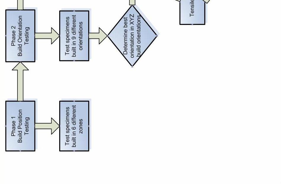
17 Figure 1: Research Plan 5
18 CHAPTER TWO: LITERATURE REVIEW 2.1 Rapid Prototyping Systems and Industry Use Rapid prototyping, also known as layer manufacturing, consists of several different technologies. RP machines vary in size and building method and build materials but they all build in a layering method. The main classes of RP machines are: Stereolithography (SLA), Selective Laser Sintering (SLS), Multi-Jet Modeling (MJM) and Three Dimensional Printing (3DP). SLA is the oldest RP technology and one of the most widely used. The SLA process consists of a vat of liquid resin and a laser to solidify the resin layer by layer. Several manufactures produce SLA machines with varying build envelopes and layer thicknesses. The standard layer thickness for an SLA machine is 0.05 mm for a standard resolution machine. A benefit of SLA is the variety of materials that can be selected for use. Materials vary from ABS like to ceramic filled resins to produce high strength and temperature resistance. SLA machines use a support structure that has to be removed after the part is complete. The SLS process use a laser to sinter a powder material spread onto the build platform. SLS uses a similar method to that of the Z Corporation 3DP with a feed platform and a build platform. A powder material is spread from a feed platform to the build platform where the cross section is sintered by a laser. The standard layer thickness for the SLS process is 0.1mm. The SLS process has a variety of materials available from plastics, nylons, flexible materials and metals. 6
19 Multi-Jet Modeling is a newer technology that uses a UV light to cure a UV curable resin that is deposited layer by layer. The resin is deposited by a print head assembly in the correct cross section and then cured by the passing UV lamp. The material is cured up to three layers deep helping to eliminate the weakness between layers of RP parts. The layer thickness of MJM machines depends on the manufacture; it can range from mm. The MJM machine uses a self contained material cartridge instead of the vat of resin like SLA. For this reason it is seen as a more office friendly machine. In the industry, 3DPs are considered to be office friendly and entry level systems. 2.2 Three Dimensional Printing in Industry The term 3DP has grown to consist of several technologies including: Stratasys Dimension FDM, 3D System s Invision and Thermojet MJM, Objet Polyjet, SolidScape MJM, and the Z Corporation 3DP. The lower cost office friendly machines are becoming grouped as 3DP. Based on conducted surveys, Terry Wohlers of Wohlers Associates stated that functional models will account for the majority of prototypes produced by the rapid prototyping industry [9]. While there has been research conducted on the accuracy of the 3D printers, little to no public work has been performed for the strength and mechanical properties of models. For prototypes to be successfully used as functional models, more research will be required in this area. 7
20 Z Corporation introduced its first 3DP the Z402 in The first 3DP used a starch or plaster based powder material with a water-based binder [9]. The Spectrum Z510 was introduced in It can print in full 3D color and is mostly being used in non-functional prototyping such as architectural, medical and consumer product models. The Z Printers excel as low cost fast prototyping machines. 2.3 Z Corporation Three Dimensional Printer Operation The Spectrum 510 is a powder-based 3DP system that uses print heads to jet a binder onto the bed of powder. The build area of the printer consists of two platforms, a feed platform and a build platform, as well as a printing assembly (Figure 2). 8

21 Figure 2: The build area of the Spectrum Z510 and schematic of the Z Corporation 3D printer. The preprocessing software will slice the 3D part into 2D slices and send the slices to the printer. The print head assembly will move from right to left depositing binder for each 2D slice of the part. The print head travels from back to front depositing binder, this is also known as the fast axis. Once the layer is completed the build platform (Z-axis) lowers a layer and the feed platform rises to spread powder to the build side. A roller spreads the powder from the feed side to the build (left to right) for 9
22 each layer of the part. The layer thickness can be adjusted from mm. The build envelope for the Spectrum Z510 is 254 mm x mm x mm. The entire process is repeated until the part is complete. The print head assembly uses four standard Hewlett Packard # 11 ink jet print heads to deposit a liquid adhesive binder (one for each color; clear, magenta, cyan, and yellow) onto the bed of powder layer by layer (Figure 1). The print heads are installed into the print head carriage and the black ink is purged out. Once this is complete the print heads are aligned to ensure the proper building. The print heads have a build life of approximately 1100mL of binder deposited [12, 13]. The print quality will decrease as the print head approaches this limit and the part quality will be affected. The Z Corporation 3DP does not use support structure because the unbound powder acts as support structure. Upon completion of the build, the part is encased in loose powder that is then brushed away to remove the part. The part is currently in the green state and is relatively delicate, therefore it needs to be infiltrated with a material to increase the strength. Parts directly removed from the machine can contain moisture, which will inhibit the infiltration process and possibly decrease strength. To ensure all of the moisture is removed from the parts they are baked in a convection oven. The parts, specifically the binder, will start to break down if baked at too high of a temperature. Due to its flexibility and dimensional accuracy, 3DP systems can be used to create very complex prototypes. Figure 3 a & b show two such complex prototypes of a cylinder head and gear assembly, respectively, created in Z-Corp Spectrum 510 3DP system. These prototypes clearly show the ability and beauty of this powder based RP technology in mimicking external features of complex geometries. 10
 a thorough")

23 (a) (b) Figure 3: Prototypes having complex geometry created in Z Corporation 3DP machine (a) a thorough engine block and (b) a detailed gear case. (Courtesy: Mydea Technologies Corporation, Orlando, FL printed with permission) 11
24 When infiltrating Z Corporation printed prototypes several methods can be used depending on the infiltrant type. When using a CA three different methods can be used to infiltrate the parts. Parts can be dipped into a vat of CA. This method is fast and effective but requires a large amount of CA. To dip parts a container is filled with CA and the part is lowered slowly into the liquid and maneuvered to fully coat the prototype. The part is then drained and allowed to dry on a nonstick surface. Another method is to drip the CA onto the surface of parts using a small nozzle and squeeze bottle. The drip method is time consuming and does not produce as good of a visual model as the dip method. However large amounts of CA are not required for this method. The third method is to spray the CA using compressed air and a spray gun. The spray method is not used by many users due to the amount of waste produced. The submersing or dripping CA are the preferred methods. Infiltrating with epoxy varies depending on need. The preferred method for infiltrating with epoxy is to brush the epoxy on the surface. Epoxy is mixed into a container and stirred properly. Then the epoxy is brushed onto the prototype completely coating the part until it will not absorb anymore infiltrant. Parts can be submerged into epoxy similar to with CA. The submersed parts can also be introduced to vacuum or pressure to help the epoxy penetrate the part 100%. Heat can also be introduced to the submersed part to lower the viscosity and increase the absorption of infiltrant into the part. 12
25 2.4 Advantages of Z Corporation 3DP The Spectrum Z510 has many advantages over other 3DP systems. Z Corporation printers are the only RP machines that can print in full 3D color. The Z Corporation 3D printers have the fastest build speed of any machines in the industry. They also have the lowest material cost per cubic inch of any RP machine. The ability to print color increases the amount of different applications the machines can be used. Design engineers can print a part with the finite element analysis directly on the part for design reviews. Parts can be labeled with design changes or notes printed directly on the part. Since the prototypes built on the Spectrum Z510 do not use a support structure (though some geometries do require fixtures that do have associated waste), working assemblies can be printed directly on the machine in one build. Z Corporation also produces a material that can be used to print molds to pour metal into directly. This material allows users to create one off cast metal parts in a much shorter time than traditional methods. These are some of the reasons that Z Corporation printers have become one of the most widely used equipment in the industry. 2.5 Infiltration Options Cyanoacrylates Cyanoacrylates (CA) are a one-part liquid adhesive that cures rapidly at room temperature. Cyanoacrylates were first discovered in 1951 when researchers at Tennessee Eastman attempted to measure the refractive index of these materials on an 13
26 Abbe refractor and they discovered the prisms of the refractometer had been bonded together [14]. These materials have the ability to cure without the need for an added curing agent unlike epoxies. A variety of materials are used as stabilizers to prevent premature curing of the cyanoacrylate. CA works well as an adhesive and infiltrant due to its rapid rate of initiation with a vast amount of materials. To manufacture alkyl cyanoacrylate monomers, 1, it involves the Knoevenagel reaction of formaldehyde, 2, with an alkyl cyanoacrylate,3, and a base such as a secondary amine, as the catalyst, shown in figure 4 [14]. Figure 4: Chemical equation of alkyl cyanoacrylate monomers. [4] The low viscosity of CA also makes a good infiltrant. There are several different types of CA. The most widely used is ethyl cyanoacrylate due to its fast cure speed and 14
27 ease of manufacturing [14]. Cyanoacrylates have several drawbacks such as odor, limited solvent resistance, limited thermal stability [14]. For infiltrating purpose a good monomer is the Methoxethyl because it is a low odor and low bloom CA. A phenomenon that affects Z Corporation parts directly is blooming. Blooming is the formation of a white residue on the surface of the part due to the evaporation of small amounts of the monomer from where it is applied onto the surface [14]. The use of a higher molecular weight monomer can eliminate this problem Epoxy Epoxy resins are considered one of the most versatile polymers with many uses in many different industries. Epoxy resin systems can be used for several applications such as adhesives, potting compounds and molding compounds. Epoxies have several advantages such as excellent adhesion to a variety of materials, relatively low shrink rate, and a cross linked structure that confers excellent resistance to environment [15]. Epoxy is composed of two components, a resin and a curing agent also known as hardner. They are so versatile because they can be formulated to meet a broad range of specific applications [15]. Epoxies are widely used due to their good wetting characteristics and ability to bond with a wide variety of materials. When the two are mixed a chemical reaction occurs turning the epoxy into a solid. Epoxy resins are considered a thermo-set polymer because when cured it is irreversible, rigid, and relatively unaffected by heat [16]. The thermosetting reaction is the joining of many small molecules by chemical reaction to produce an extended network structure. Epoxy 15
28 molecules in the pure state can be stored at room temperature for years without reaction [15]. The curing of epoxy creates heat as a result of the chemical reaction. Cured epoxies have good chemical resistance and tensile strength. If the correct amount of resin and hardener are not used the epoxy will not cure properly. Many different types of epoxies are available but the most common is Diglycidyl ether of bisphenol A (DGEBA). The chemical structure of DGEBA is shown in figure 5. Figure 5: Structure of Diglycidyl ether of bishpenol A (DEGBA) [16]. 16

29 CHAPTER THREE: METHODOLOGY 3.1 Materials and Equipment Used Specimens were built in the Spectrum Z 510 using ZP 130 powder along with ZB 58 binder was for this research. The ZB 130 powder is a plaster-based high performance build material [13]. There are numerous variables that can have an effect on the strength of parts. The Z Corporation software has several adjustable build parameters that will affect strength and accuracy, such as shell saturation levels, core saturation levels, bleed compensation, and layer thickness. The shell and core saturation levels refer to the ratio of binder deposited on the outer shell and inner center of the part (figure 6). Turning on bleed compensation can affect the accuracy of parts. Figure 6: Definition of shell and core structure of prototype. 17

30 Some other variables that effect part strength that cannot be controlled with software are build to build variation, print head life, humidity, and other environmental variables. The infiltrant used has the strongest effect on the part strength. The two main types of infiltrants used are cyanoacrylates and epoxies. The use of CA will allow for quicker turnaround due to the fast cure time and it also enhances the appearance of color models. Epoxies are used to give the parts higher strength and durability. 3.2 Phase 1 Effects of Build Position on Tensile Strength Specimen Design and Development The testing specimens were created using Solidworks CAD software package. In addition, a stereolithography (stl) file was exported and used by the printer to create the part. The dimensions of the tensile testing specimen are shown in Figure 7. Figure 7: Schematic showing the dimensions of tensile specimen used in this study 18
31 The thicker dog bone sample size of 7.11 mm was used to better represent realworld parts. A smaller 3.18 mm thick specimen would allow infiltrants to penetrate the specimen 100% for all infiltrants. Thicker specimens do not allow a part to be completely infiltrated for all infiltrants. When the infiltrant does not penetrate 100%, the core will remain in the green state decreasing the overall strength. The tensile testing specimens were created with the 3DP process using the default software settings for the Spectrum Z510. Shell and core saturation levels were set to 100%, with the binder/volume ratio for the shell and for the core. The shell and core saturation levels can be adjusted to vary the binder ratio. The bleed compensation was turned on with default settings (X: , Y: and Z: ) and the layer thickness was set to mm for all specimens. In Phase 1, the specimens were built in the six build zones of the build platform (Figure 8). 19

32 Figure 8: Schematic showing six build zones used to create models for Phase 1 testing These zones were selected to represent the major building areas of the printer. The specimens were stacked six high in each zone to eliminate the build to build variations. New print heads were installed before each build to ensure the best possible results. Print heads function best for the first third of their life cycle [13]. Once the build was complete, the specimens were left in the Spectrum 510 for an hour. This allows the parts to dry and finish curing before being handled. The parts were then removed from the printer and placed in a convection oven at 82 degrees Celsius for one hour to 20
33 remove all of the moisture in the parts. Moisture causes a reaction to start the curing process in cyanoacrylates. If all moisture is not removed from the part it will begin to set before it fully infiltrates into the part. When infiltrating with epoxy, the moisture will limit the amount of epoxy infiltrated and create a weaker part. After the bake cycle, the specimens were completely depowdered. Next the specimens were infiltrated with System Three Clear Coat epoxy. The brush on method was used to apply the epoxy to the dried specimens. Several coats of epoxy were applied until the parts were completely saturated and epoxy would not infiltrate the specimens anymore. They were then allowed to cure at room temperature (25 C ) for 72 hours before testing Uniaxial Tensile Testing Uniaxial tension testing was performed using the screw driven Instron universal tester (Model3369, Instron Co., USA) with a constant crosshead speed of 5 mm/min for all phases. The samples for the position testing were tested following ASTM D638 Standard Test Method for Tensile Properties of Plastics. Following the ASTM standard six samples per build position were tested. The average stress per build location was tested to determine the effect of build location on infiltrated part strength. 21
34 3.3 Phase 2 Effects of Build Orientation on Mechanical Behavior Specimen Fabrication Specimens for Phase 2 were built using the same sample size and following the same procedures as Phase 1. The specimens were built in nine different build orientations to determine the effects of build orientation on tensile strength. The samples for the orientation testing were built in nine different orientations along the XYZ coordinate system (Figure 9). 22

35 Z-0 Z-90 Z-45 Figure 9: Schematic displaying nine build orientations for phase 2 testing to determine the effects of orientation on tensile strength of prototypes. The post processing methods for the orientation samples were the same as the position testing samples. The specimens were baked and infiltrated with the System Three Clear Coat Epoxy with the exact same infiltrating process. 23
36 3.3.2 Uniaxial Tensile Testing The uniaxial tension testing was performed using the screw driven Instron 3360 with a constant crosshead speed of 5 mm/min for all phases. The samples for the position testing were tested following ASTM D638 Standard Test Method for Tensile Properties of Plastics. Following the ASTM standard six samples per nine build orientations were tested. The average stress per build orientation was tested to determine the effect of build location on infiltrated part strength. 3.4 Phase 3 Effects of Infiltrating Material on Mechanical Behavior Specimen Fabrication The third phase of the research test is the mechanical properties of seven different infiltrants. Samples were built in three different orientations (Figure 10) using the same sample size and post processing methods as the first two phases. The build orientation for phase 3 was selected based on the results from phase 2. The materials for phase 3 consist of 2 cyanoacrylates and 5 epoxies. Z Corporation distributes a CA (Z-Bond 101) and an epoxy (Z Max) to be used with the 3DP system. These materials were used as a baseline for testing. Of the 5 epoxies tested two were high temperature epoxies (HTR 212 and EEL 335). The seven materials and cost per ounce are in Table 1. 24
37 Table 1 Cost comparison of materials used during infiltration of Z Corporation samples Infiltrant Type of Infiltrant Cost per Ounce Z Bond 101 Cyanoacrylate $12.75 CA Plus N5 Cyanoacrylate $9.06 Z Max Epoxy $1.61 System Three Clear Coat Epoxy $0.85 Ad-Tech Epoxy CER-112 Epoxy $1.30 Resin Services HTR-212 High-temp Epoxy $0.58 Ad-Tech Epoxy EEL-335 High-temp Epoxy $0.62 The process for infiltrating with the high temperature epoxies is the same until the curing process. Once the samples are infiltrated they are left to cure at room temperature for 24 hours then placed in a convection oven and heated. The samples are baked from 82 degrees C up to 176 degrees C increasing the temperature 50 degrees every hour. 25
 in each build orientation and material was determined from the specimens used in phase 3.")
38 90-90 Z Figure 10: Diagram to display the three build orientations for Phase 3 Material infiltration testing Density and Porosity Measurement The geometric bulk density ( ρg ) in each build orientation and material was determined from the specimens used in phase 3. To determine the geometric bulk density a section of the specimen was cut to a uniform size to determine the volume. The specimens were then weighed to determine its mass and the geometric bulk density was calculated using equation 1. 26
39 Geometric Bulk Density ( ρg ) = Mass/Volume (1) The porosity and volumetric bulk density of the seven infiltrating materials were determined using the immersion technique. The apparent density is the ratio of the mass in air to a given volume at a stated temperature. Porosity of a material is the measure of the percentage of water permeable voids in a compacted sample. Specimens were soaked in pure water for 2 hours. The specimens were removed from the water, drained and dried off. Then the samples were weighed for the saturated mass when the surface dry condition was reached. The samples are then measured again to find the total weight in water at 25.5 C the immersed mass (m i ). The samples are baked to complete the drying process and measured for the dry mass (m d ). Equations (2) and (3) were used to determine the volumetric bulk density ( ρ v ), and the apparent density ( ρa ). The apparent porosity ( ζ a ) of the specimens were evaluated using equation (3), where as ρl is the density of the liquid. ρ v m d ρ ( m s m i ) L (2) ρ a m d ( m d m i ) L ρ (3) ( m s m d ζ a 100 ( m s m i ) (4) 27
40 3.4.3 Specimen Infiltrant Absorption The samples for phase 3 were weighed in air after drying and before infiltration. They were also weighed after the final curing of infiltrated specimens. The percentage of infiltrant absorbed by the specimens in phase 3 was determined to relate to the tensile strength of the specimens. Equation 4 was used to determine the percentage of infiltrant absorbed based on weight change [17]. (5) 3.4.4Uniaxial Tensile Testing Testing was performed in three phases. In each phase, tensile testing was performed following ASTM D638 testing six samples per test. Phase 1 - Position Testing was to determine how the build position affected tensile strength. Phase 2 - Orientation Testing was to determine if build orientation effects tensile strength. Finally, Phase 3 - Infiltration Materials were tested to determine strength of several different infiltrants Point Bend Testing Flexural testing was performed using the seven materials and build orientations of Phase 3 for infiltration. Specimens were created using the same methods as tensile testing. Testing was performed using the Instron 3360 and the flexural testing setup. 28
41 The flexural testing specimens were created with a 7.11 mm thickness. The testing was performed according to ASTM D790 using the three point method and six samples per test. The cross head speed was set to mm/mm/min. 3.5 Statistical Analysis The t test is a statistical method to determine the significance of results between groups of data. The t test tells if the variation between two groups is significant. Multiple t tests can not be used because as the number of groups grows, the number of pair comparisons grows. Using seven groups there would be 21 pairs. The analysis of variance (ANOVA) is performed to determine the significance of testing of three or more groups. ANOVA puts all of the data into one number and gives one P value for the null hypothesis. The ANOVA procedure attempts to analyze the variation in a set of responses and assign portions of this variation to each of a set of independent variables [18]. The objective of analysis of variance is to locate the important independent variables and determine how they affect the response [18, 19]. In this research there is only one factor, stress, therefore a one way ANOVA is used to determine significance. The results for ANOVA are displayed in a table format. The first column gives the source associated with each sum of squares of deviation; the second column gives the corresponding sums of squares (SS); the third and forth columns give the degrees of freedom (df) and mean squares (MS), respectively [18]. A calculated value of F is usually shown in the fifth column. The F test is used in testing the equality of treatment 29
42 means. The last two columns display the P value and the F critical value respectively. The F critical value is a tabular value of the F distribution based on the chosen alpha level and the degrees of freedom. 30
43 CHAPTER FOUR: RESULTS 4.1 Phase 1 Effects of Build Location on Tensile Strength Phase 1: Position Testing was performed to determine if build placement had an effect on the tensile strength of parts. When the powder is spread for the new layer it is spread from left to right, therefore it is believed that the density of powder in zones 1 and 4 will be greater and will produce stronger parts. The average stress of the samples for all build zones was within 1.1 MPa. The samples built in zone 2 had the highest average stress but also had the largest error. A graph of the average tensile stress for the six different build zones is shown in Figure
44 Tensile Strength (MPa) Position 1 Position 2 Position 3 Position 4 Position 5 Position 6 Build Location (see figure 2) Figure 11: Graph of the average tensile strength of Z Corporations samples infiltrated with System Three Clear Coat Epoxy built in the six different zones Statistical analysis was performed to determine the significance of the results for the position testing. The large P value shows that theses results did not have a great significance. The ANOVA results are shown in table 2 below. 32
45 Table 2 Anova analysis for position testing Anova: Single Factor SUMMARY Groups Count Sum Average Variance Build Position Build Position Build Position Build Position Build Position Build Position ANOVA Source of Variation SS df MS F P-value F crit Between Groups Within Groups Total Phase 2 Effects of Build Orientation on Tensile Strength Phase 2: Orientation Testing was performed to determine if the build orientation of parts has a large effect on the strength of the final part. The parts built in 0-90 and orientations had a higher average stress (17.9MPa and 16.78MPa respectively) than the other orientations. Specimens built in the vertical Z direction had the lowest tensile strength. The average tensile stress for each build orientation is shown in Figure
46 Tensile Strength (MPa) Z-0 Z-45 Z-90 Build Orientation (see figure 3) Figure 12: Graph of the average tensile strength of Z Corporations samples built in nine different orientations infiltrated with System Three Clear Coat Epoxy The statistical significance of the orientation testing was determined using the Analysis of Variance testing. It was determined that the results of the orientation testing were highly significant with a P value of 1.11 x 10^-15. Table 3 displays the results of the ANOVA testing. 34
47 Table 3 Anova for orientation testing Anova: Single Factor SUMMARY Groups Count Sum Average Variance Build Orientation Build Orientation Build Orientation Build Orientation Build Orientation Build Orientation Build Orientation z Build Orientation z Build Orientation z ANOVA Source of Variation SS df MS F P-value F crit Between Groups x10^ Within Groups Total Phase 3 Effects of Infiltrating Material on Mechanical Behavior Phase 3: Infiltrant Testing was to determine what affects the different infiltrants used with Z Corporation on the parts strength. The samples were built in three orientations; 0-90, 90-90, and Z-90. The x-90 orientation had the highest strength and smallest error from phase 2. During phase 3 two different CAs were used, both with a viscosity of 35
48 2cps. These materials both had the same penetration depth within ± mm. The samples infiltrated with the CA Plus had a higher strength. Specimens infiltrated with CA Plus had an average of 5MPa while Z Bond 101 had an average of 3.5MPa. The CA materials displayed the smallest error among all infiltrating samples. The average tensile strength for the seven infiltrating materials in all three build orientations is shown in Figure 13. The epoxy branded by Z Corporation (Z Max) produced the highest average stress of MPa in the 0-90 build orientation. All three build orientations were fairly consistent within 2.5 Mpa of each other. The materials with the lowest tensile strength were the high temperature epoxies and they also had the shallowest penetration depth of infiltrants. The System Three Clear Coat epoxy and CER 112 epoxy were comparable in tensile strength. 36
49 20.0 Z Bond 101 CA Plus N5 Z Max CER 112 System Three Clear Coat EEL 335 HTR Tensile Strength (MPa) z-90 Build Orientatoin (see figure 4) Figure 13: A comparative plot showing the average tensile strength of samples built in three orientations and infiltrated with seven different materials The testing performed for the seven different infiltrating materials was determined to be highly significant using ANOVA testing. The P value of 1.47 x 10^-66 shows that theses results have a great significance. The ANOVA results are shown in table 4 below. 37
50 Table 4 Anova for infiltration material Anova: Single Factor SUMMARY Groups Count Sum Average Variance Z Max Build Orientation Z Max Build Orientation Z Max Build Orientation z System Three System Three System Three z CER CER CER 112 z EEL EEL EEL 335 z HTR HTR HTR 212 z Z Bond Z Bond Z Bond z CA Plus CA Plus CA Plus z ANOVA Source of Variation SS df MS F P-value F crit Between Groups x10^ Within Groups Total The average flexural strength of Z Corporations samples infiltrated with seven different materials and built in the three different orientations from phase 3 is shown in Figure 14. The Z Corporation epoxy, Z Max, displayed the highest flexural strength of 38
51 36.06 MPa in the build orientation. The specimens infiltrated with cyanoacrylates experienced the lowest average flexural strength. The high temperature epoxies had higher flexural strength than expected based on tensile testing Z Max System Three CER 112 EEL 335 HTR 212 Z Bond CA Plus Flexural Strength (MPa) Z-90 Build Orientation Figure 14: Graph of the average flexural strength of Z Corporations samples infiltrated with seven different materials and built in the three different orientations from phase 3 The statistical significance of the 3pt bend testing was determined using the Analysis of Variance testing. It was determined that the results of the orientation testing were highly significant with a P value of 1.07 x 10^-36. Table 5 displays the results of the ANOVA testing. 39
52 Table 5: Results of ANOVA analysis of three-point bend test results Anova: Single Factor SUMMARY Groups Count Sum Average Variance Z Max Build Orientation Z Max Build Orientation Z Max Build Orientation z System Three System Three System Three z CER CER CER 112 z EEL EEL EEL 335 z HTR HTR HTR 212 z Z Bond Z Bond Z Bond z CA Plus CA Plus CA Plus z ANOVA Source of Variation SS df MS F P-value F crit 1.07x10^a- Between Groups Within Groups Total The geometric bulk density was calculated for each build orientation and infiltration material from phase 3. Figure 15 represents the geometric bulk density of the samples from phase 3. Specimens infiltrated with Z Max had the highest bulk density. When all infiltrating materials were compared the geometric bulk density was consistent 40
53 among the specimens. The geometric bulk density results show that the density of parts has an affect on part strength Z Max System Three Epoxy CER 112 EEL 335 HTR 212 Z Bond CA Plus Density (g/cm^3) z-90 Build Orientation Figure 15: Geometric bulk density of 3DP specimens infiltrated with the seven infiltrating materials in phase 3 The porosity and apparent density were determined using the same samples from the bulk density. Figure 16 is a comparison of the porosity for the seven infiltration materials. 41
54 Z Max System Three Epoxy CER 112 EEL 335 HTR 212 Z Bond CA Plus Porosity % z-90 Build Orientation Figure 16: Porosity of 3DP specimens infiltrated with the seven infiltrating materials in phase 3 The infiltrated specimens with the lower porosity experienced higher tensile strength. The Z Max infiltrant had the lowest porosity average of all build directions at 8.59% and it had the highest strength. The high temperature epoxies have a high porosity due to the infiltrant not penetrating completely into the part. The two CA materials had a relatively low porosity and tensile strength. The apparent density (Figure 17) of the specimens was relatively higher than the geometric bulk density. 42
55 6.000 Z Max System Three Epoxy CER 112 EEL 335 HTR 212 Z Bond CA Plus Apparent Density (g/cm^3) z-90 Build Orientation Figure 17: Apparent density of 3DP specimens infiltrated with the seven infiltrating materials in phase 3 The cyanoacrylates had a higher apparent density than other materials. The epoxies displayed the same ranking order as in bulk density. Figure 18 is a plot of porosity against the tensile strength of the specimens infiltrated with seven different materials. 43
56 20 Z Bond CA Plus Z Max System Three Epoxy CER 112 EEL 335 HTR Tensile Strength (MPa) Porosity (%) Figure 18: Plot of tensile strength vs. porosity of samples infiltrated with seven infiltrants The specimens for phase 3 were weighed before and after infiltrating to determine the amount of material absorbed. The amount of infiltrant absorbed is consistent with the tensile strength/porosity relationship. The three regular temperature epoxies absorbed the most infiltrant and had the highest tensile strength see figure
57 Z Bond 101 CA Plus N5 Z Max CER 112 System Three Clear Coat EEL 335 HTR Tensile Strength (MPa) % of Infiltrant Absorbed Figure 19: A graph of the amount of infiltrant absorbed vs. tensile strength 45
58 CHAPTER FIVE: DISCUSSION The results of the build position testing were not consistent with suggestions of build placement by Z Corporation. It is suggested that you build parts in zone 1 (default build location) for the highest strength and speed. An optimization study was performed on placement that suggest placing parts to the far right in zones 3 or 6 for best results [12]. The zone that showed the highest strength also had the largest error among specimens. The large error could be due to several build and post processing variables such as moisture in parts before infiltration or the infiltrated density variation between samples. Due to the tensile strength of all build position being similar the results from the position testing show that the build placement of parts does not have a large impact on tensile strength. It can be concluded that build location does not have a large impact because most of the part strength is determined by the infiltration material. The build orientation of parts has a larger effect on the tensile strength of the final part than the build location. Due to the layering build process of RP parts, the parts printed in the Z direction have a lower tensile strength when compared to the other build orientations. The bond between layers is not as strong as each layer itself. Therefore when tension is applied along the direction of the 2D profile the parts were stronger then when applied in the direction of layers. The z direction specimens also had a lower tensile strength because they absorbed the smallest amount of infiltrant for most samples. The parts built in the 0-90 and orientations had higher average strength than the other build orientations. This is partially due to the infiltrant penetrating deeper into side walls of a part than the up facing surfaces of a sample [13]. The parts build in 46
An Overview of Methods for Rapid Prototyping and Near Net Shape Manufacture. Ivor Davies. RP&T Centre WMG, University of Warwick
 An Overview of Methods for Rapid Prototyping and Near Net Shape Manufacture Ivor Davies RP&T Centre WMG, University of Warwick 2 Contents Rapid Prototyping Basic Principle Data Requirements RP Processes
THE ASPECTS ABOUT RAPID PROTOTYPING SYSTEM
 THE ASPECTS ABOUT RAPID PROTOTYPING SYSTEM Adrian P. POP 1, Petru UNGUR 1, Gheorghe BEJINARU MIHOC 2 1 University of Oradea, e-mail: adippop@yahoo.com; petru_ungur@yahoo.com; 2 Transilvania University
Company profile. The world s leading provider of 3D printing and manufacturing systems taking visions from idea to reality
 Company profile The world s leading provider of 3D printing and manufacturing systems taking visions from idea to reality Dual headquarters Israel and US Global workforce of over 1,600 employees Strong
Johnathon Wright Application Engineer Phoenix Analysis & Design Technologies www. PADTInc.com
 Johnathon Wright Application Engineer Phoenix Analysis & Design Technologies www. PADTInc.com PADT is an Engineering Services Company Three Business Groups Simulation Training, Sales & Services Product
Major player in the 3D Printing Market
 Major player in the 3D Printing Market PolyJet FDM High- Performance Resins Production-Grade Thermoplastics High Feature Detail & Finish Highly Durable Parts Multi-Material Printing Functional Parts Makerbot
What is Rapid Prototyping?
 Rapid Prototyping New Technologies for the Classroom What is Rapid Prototyping? A set of processes that allows a concept or idea to be turned into a three-dimensional physical object, usually in a matter
STUDY OF SHAPE DEPOSITION MANUFACTURING
 STUDY OF SHAPE DEPOSITION MANUFACTURING 1 Ashish Bhorkade, 2 Chetan Bharambe, 3 Suraj Bhangale 4 Pankaj Patil 1,2,3 B.E.Scholar BVCOE&RI Nashik 4 Assistant Professor Mechanical Dept. BVCOE&RI Nashik ABSTRACT
3DP Consumables Catalog
 3DP Consumables Catalog Part Number 09572 Rev. J 13 August 2010 2010 Z Corporation. All rights reserved. Page 1 Page 2 2010 Z Corporation. All rights reserved Contents 1 Introduction... 4 1.1 Printers
Additive Manufacturing Technology
 Additive Manufacturing Technology ME 012193 Spring I 2018 By Associate Prof. Xiaoyong Tian Cell:13709114235 Email: leoxyt@mail.xjtu.edu.cn Lecture 02 Fundmental AM processes Interactions in AM processes
Additive Layer Manufacturing: Current & Future Trends
 Additive Layer Manufacturing: Current & Future Trends L.N. Carter, M. M. Attallah, Advanced Materials & Processing Group Interdisciplinary Research Centre, School of Metallurgy and Materials Additive Layer
Additive Manufacturing. Build on our experience
 Additive Manufacturing Build on our experience What is Additive Manufacturing? Additive manufacturing or rapid prototyping is almost magical. In conventional machining processes, material is removed from
SELECTIVE LASER SINTERING OF METAL MOLDS: THE RAPIDTOOLTM PROCESS. Uday Hejmadi Kevin McAlea
 SELECTIVE LASER SINTERING OF METAL MOLDS: THE RAPIDTOOLTM PROCESS ABSTRACT Uday Hejmadi Kevin McAlea Materials and Process Development Group DTM Corp., Austin TX 78759 Complex three dimensional parts can
A Comparative Study of Strength and Stiffness of Thin-Walled Specimens Fabricated By FDM and 3D Printing Technologies
 Brigham Young University BYU ScholarsArchive All Theses and Dissertations 2012-07-11 A Comparative Study of Strength and Stiffness of Thin-Walled Specimens Fabricated By FDM and 3D Printing Technologies
Plastics for Additive Manufacturing
 Sources: voxeljet, Materialise NV, Iris van Herpen Plastics for Additive Manufacturing Dr. Thomas Büsgen Bayer MaterialScience AG 20 th November 2013, 3D Printing & Additive Manufacturing Industrial Applications
Comparative Fatigue Analysis of Metals and Polymers for Engineering Applications
 University of Arkansas, Fayetteville ScholarWorks@UARK Mechanical Engineering Undergraduate Honors Theses Mechanical Engineering 5-2012 Comparative Fatigue Analysis of Metals and Polymers for Engineering
ADDITIVE MANUFACTURING IN PRINTED CIRCUIT BOARD ASSEMBLY PROCESSES
 As originally published in the SMTA Proceedings ADDITIVE MANUFACTURING IN PRINTED CIRCUIT BOARD ASSEMBLY PROCESSES Zohair Mehkri, David Geiger, Anwar Mohammed, Murad Kurwa Flex Milpitas, CA, USA Zohair.mehkri@flextronics.com
3 Major 3d printing process and technology introduction
 3 Major 3d printing process and technology introduction Summary After several decades of development, Now there are a variety of 3D printing technology process, from the categories divided into extrusion
Appendix A Physical properties of rammed earth
 Appendix A Physical properties of rammed earth 99 A.1 General The level and extent of testing rammed earth materials depends on specific application and novelty of the material in use. Where a proven material
ADDITIVE MANUFACTURING CERTIFICATE PROGRAM BODY OF KNOWLEDGE
 ADDITIVE MANUFACTURING CERTIFICATE PROGRAM BODY OF KNOWLEDGE RUBRIC 1.0 OVERVIEW of AM 1.1 Definition of AM 1.1.1 Evolution of AM definitions 1.1.2 Current ASTM 1.2 Key Elements of AM 1.2.1 Sources of
FORMLABS WHITE PAPER: A Guide to Post-Curing Formlabs Resins. March 2018 formlabs.com
 FORMLABS WHITE PAPER: A Guide to Post-Curing Formlabs Resins March 218 formlabs.com Table of Contents Abstract 3 Methodology 4 Introduction 5 Recommended Cure Settings: Clear. 6 Recommended Cure Settings:
ENGINEERING APPLICATIONS OF WOOD WITH REFERENCE TO PROTOTYPE MANUFACTURING USING RAPID PROTOTYPING TECHNOLOGY.
 ENGINEERING APPLICATIONS OF WOOD WITH REFERENCE TO PROTOTYPE MANUFACTURING USING RAPID PROTOTYPING TECHNOLOGY. Rapid Prototyping Rapid Prototyping Technology (RPT) is an emerging tool in prototypes
Additive Manufacturing Challenges Ahead
 Additive Manufacturing Challenges Ahead Dr. S. SELVI Associate Professor, Dept. of Mechanical Engineering Institute of Road and Transport Technology, Erode 638 316. selvimech@yahoo.com Received 25, November
PES INSTITUTE OF TECHNOLOGY BANGALORE SOUTH CAMPUS Hosur Road, (1K.M. Before Electronic City), Bangalore DEPARTMENT OF MECHANICAL ENGINEERING
, Bangalore DEPARTMENT OF MECHANICAL ENGINEERING") PES INSTITUTE OF TECHNOLOGY BANGALORE SOUTH CAMPUS Hosur Road, (1K.M. Before Electronic City), Bangalore 560 100 DEPARTMENT OF MECHANICAL ENGINEERING SCHEME AND SOLUTION - I ST INTERNAL TEST Subject :
PES INSTITUTE OF TECHNOLOGY BANGALORE SOUTH CAMPUS Hosur Road, (1K.M. Before Electronic City), Bangalore 560 100 DEPARTMENT OF MECHANICAL ENGINEERING SCHEME AND SOLUTION - I ST INTERNAL TEST Subject :
ebook Prototyping and Manufacturing Services to Help Satisfy Modern Market Expectations
 ebook Prototyping and Manufacturing Services to Help Satisfy Modern Market Expectations Appearance prototype of clock radio for award-winning designer Robert Bronwasser. (Courtesy of Robert Bronwasser
FORMLABS WHITE PAPER: A Guide to Post-Curing Formlabs Resins. March 2018 formlabs.com
 FORMLABS WHITE PAPER: A Guide to Post-Curing Formlabs Resins March 218 formlabs.com Table of Contents Abstract 3 Methodology 4 Introduction 5 Recommended Cure Settings: Clear. 6 Recommended Cure Settings:
Models available: Markforged Onyx One Markforged X3 Many FDM models from numerous OEM s worldwide
 Markforged Onyx One Markforged X3 Many FDM models from numerous OEM s worldwide FFF uses a string of solid material (filament), pushing it through a heated nozzle and melting it in the process. The printer
Contents. 1. Introduction to Materials Processing Starting Materials 21. Acknowledgements
 Preface Acknowledgements xiii xv 1. Introduction to Materials Processing 1 1.1 Materials Processing: Definition and Scope 1 1.2 Three Approaches to Materials Processing 4 1.3 Materials Processing Steps
Evaluation Guide for Selecting the Best FRP Composite Process for Your Project
 19 48-2018 Evaluation Guide for Selecting the Best FRP Composite Process for Your Project Liquid Composite Molding (LCM) vs. SMC ABSTRACT In this report, we compare and contrast the properties of the two
Characterization of Physical Properties of Roadware Clear Repair Product
 Characterization of Physical Properties of Roadware Clear Repair Product November 5, 2009 Prof. David A. Lange University of Illinois at Urbana-Champaign Introduction Roadware MatchCrete Clear (MCC) is
PHYSICO-MECHANICAL PROPERTIES CHARACTERIZATION OF THE PARTS FROM PA 2200 MANUFACTURED BY SELECTIVE LASER SINTERING TECHNOLOGY
 PHYSICO-MECHANICAL PROPERTIES CHARACTERIZATION OF THE PARTS FROM PA 2200 MANUFACTURED BY SELECTIVE LASER SINTERING TECHNOLOGY Borzan C.Ş.; Berce P.; Chezan H.; Sabău E.; Radu S.A.; Ridzon M.; borzan_cristina@ymail.com
INJECTION MOLDING WITH AN ADDITIVE MANUFACTURING TOOL
 INJECTION MOLDING WITH AN ADDITIVE MANUFACTURING TOOL Jake W. Nelson, James J. LaValle, Brian D. Kautzman, and Jeremy K. Dworshak, Steinwall, Minneapolis, MN Eric M. Johnson, Ph.D. John Deere Moline Tech
Effect of Hydrocarbon Solutions on Polymer Concrete
 Dr. Sanaa Abdul Hadi Applied Sciences Department, University of Technology/Baghdad. Mustafa Hassan Omar Applied Sciences Department, University of Technology/Baghdad. Email:entaomritofi8@yahoo.com Received
Producing Metal Parts
 Producing Metal Parts CNC vs. Additive Manufacturing www.3dhubs.com METAL KIT 2 Introduction This Kit discusses how to select the right manufacturing process for metal parts by comparing CNC and Additive
RAPID PATTERN BASED POWDER SINTERING TECHNIQUE AND RELATED SHRINKAGE CONTROL
 RAPID PATTERN BASED POWDER SINTERING TECHNIQUE AND RELATED SHRINKAGE CONTROL Jack G. Zhou and Zongyan He ABSTRACT Department of Mechanical Engineering and Mechanics Drexel University 3141 Chestnut Street
Industrial Engineering Applications of Rapid Prototyping
 Industrial Engineering Applications of Rapid Prototyping Dr. Denis Cormier Rochester Institute of Technology Department of Industrial and Systems Engineering Introductions 1995-2009 North Carolina State
Methods of manufacture
 1 Methods of manufacture For Ceramics (see (b)) Crush raw materials Shape the crushed raw materials (various means) Dry & fire Apply finishing operations, as needed; to achieve required dimensional tolerances
Thermal effects on stereolithography tools during injection moulding
 Loughborough University Institutional Repository Thermal effects on stereolithography tools during injection moulding This item was submitted to Loughborough University's Institutional Repository by the/an
ebook Outsourced Prototyping and Manufacturing Help Satisfy Modern Market Expectations
 ebook Outsourced Prototyping and Manufacturing Help Satisfy Modern Market Expectations Appearance prototype of clock radio for award-winning designer Robert Bronwasser. (Courtesy of Robert Bronwasser Design)
Feasibility of integral water repellent admixtures in low pressure compatible injected fill grouts
 Structural Repairs and Maintenance of Heritage Architecture XII 659 Feasibility of integral water repellent admixtures in low pressure compatible injected fill grouts C. Citto, A. E. Geister & D. W. Harvey
FULL-DENSIFICATION OF SLS PARTS BY RE-MELTING. Abstract
 FULL-DENSIFICATION OF SLS PARTS BY RE-MELTING T. NIINO and H. YAMADA Institute of Industrial Science, The University of Tokyo 4-6-1 Komaba Meguro Tokyo, 153-8505 Japan Reviewed, accepted August 4, 2004
ADDITIVE MANUFACTURING BODY OF KNOWLEDGE
 ADDITIVE MANUFACTURING BODY OF KNOWLEDGE The Additive Manufacturing Body of Knowledge was developed by the Additive Manufacturing Leadership Initiative (AMLI). AMLI is a collaborative group consisting
ME 6018 ADDITIVE MANUFACTURING
 ME 6018 ADDITIVE MANUFACTURING 1 SYLLABUS UNIT I Introduction UNIT II CAD & Reverse Engineering UNIT III UNIT IV Liquid Based & Solid Based Additive Manufacturing Systems Powder Based Additive Manufacturing
CHAPTER - 1 INTRODUCTION
 CHAPTER - 1 INTRODUCTION 1. 1.1 Polymer Matrix Composites Composite materials are formed by combining two or more materials that have different properties. The constituent materials work together to give
The University of Texas at Austin Mechanical Engineering Department, Cockrell School of Engineering Austin, TX
 In-Situ Thermal Image Correlation with Mechanical Properties of Nylon-12 in SLS Walker Wroe, Jessica Gladstone, Timothy Phillips, Austin McElroy, Scott Fish, Joseph Beaman The University of Texas at Austin
EJECTION FORCES AND FRICTION COEFFICIENTS FROM INJECTION MOLDING EXPERIMENTS USING RAPID TOOLED INSERTS. Center. Abstract
 EJECTION FORCES AND FRICTION COEFFICIENTS FROM INJECTION MOLDING EXPERIMENTS USING RAPID TOOLED INSERTS M. E. Kinsella 1, B. Lilly 2, B. Carpenter 2, K. Cooper 3 1 Air Force Research Laboratory, 2 The
INTERNATIONAL JOURNAL OF MECHANICAL ENGINEERING AND TECHNOLOGY (IJMET)
") INTERNATIONAL JOURNAL OF MECHANICAL ENGINEERING AND TECHNOLOGY (IJMET) International Journal of Mechanical Engineering and Technology (IJMET), ISSN 0976 ISSN 0976 6340 (Print) ISSN 0976 6359 (Online) Volume
INTERNATIONAL JOURNAL OF MECHANICAL ENGINEERING AND TECHNOLOGY (IJMET) International Journal of Mechanical Engineering and Technology (IJMET), ISSN 0976 ISSN 0976 6340 (Print) ISSN 0976 6359 (Online) Volume
EXPERIMENTAL STUDY OF MECHANICAL PROPERTIES OF ADDITIVELY MANUFACTURED ABS PLASTIC AS A FUNCTION OF LAYER PARAMETERS
 Proceedings of the ASME 2015 International Mechanical Engineering Congress and Exposition IMECE2015 November 13-19, 2015, Houston, Texas IMECE2015-52634 EXPERIMENTAL STUDY OF MECHANICAL PROPERTIES OF ADDITIVELY
Structural Composite Materials
 Structural Composite Materials F.C. Campbell The Materials Information Society ASM International Materials Park, Ohio 44073-0002 www.asminternational.org Contents Preface About the Author xi xv Chapter
CHOICES MATURE PROTOTYPE INSIDE P Controls & Sensors. 18 Prototyping. 22 Electronics. 30 Motors
 October 2010 REACHING OEM DESIGN ENGINEERS ACROSS CONSUMER AND COMMERCIAL MARKETS WORLDWIDE PROTOTYPE CHOICES MATURE P. 18 INSIDE 14 Controls & Sensors 30 Motors www.appliancedesign.com ap 22 Electronics
Crystal Cast 1000A : Crystal Cast 1000B By Weight 100 : 120. Appearance - Clear liquid Clear liquid Clear liquid
 Crystal Cast 1000 Two Part Casting System Water Clear, UV Stable Crystal Cast 1000 is a two component thermoset system which is water clear when cured. Crystal Cast 1000 is ideal for rapid prototyping,
H. Nouri*, B. Khoshnevis* *Department of Industrial and Systems Engineering, University of Southern California, 3710 Mcclintock Avenue, 90089
 Solid Freeform Fabrication 2017: Proceedings of the 28th Annual International Solid Freeform Fabrication Symposium An Additive Manufacturing Conference Selective Separation Shaping of Polymeric Parts H.
Strength Max User Guide
 Strength Max User Guide High-Strength Epoxy Infiltrant Description StrengthMax is a high-strength epoxy infiltrant specifically formulated for 3D Systems. StrengthMax has low viscosity and is designed to
Andreas Gebhardt. Understanding Additive Manufacturing. Rapid Prototyping - Rapid Tooling - Rapid Manufacturing ISBN:
 Andreas Gebhardt Understanding Additive Manufacturing Rapid Prototyping - Rapid Tooling - Rapid Manufacturing ISBN: 978-3-446-42552-1 For further information and order see http://www.hanser.de/978-3-446-42552-1
Developments in the Field of Rapid Prototype Production Norbert Krisztián KOVÁCS 1, a and József Gábor KOVÁCS 1, b
 Developments in the Field of Rapid Prototype Production Norbert Krisztián KOVÁCS 1, a and József Gábor KOVÁCS 1, b 1 Department of Polymer Engineering, Budapest University of Technology and Economics,
2017 Fabtech Systems, LLC. All Rights Reserved
 RESTECH+Advanced Polymer Epoxy Resin TDS Information Product Description RESTECH+ is a two-part low viscosity epoxy-amine resin designed for wet laminating carbon, glass, aramid, and other polymer fiber
Prototyping Process Choosing the best process for your project
 Prototyping Process Choosing the best process for your project Proto Labs, Inc. 5540 Pioneer Creek Dr. Maple Plain, MN 55359 P: (763) 479 3680 F: (763) 479 2679 www.protolabs.com 2009 Proto Labs. All rights
ALBERTA TRANSPORTATION SPECIFICATION FOR CONCRETE PATCHING MATERIALS
 ALBERTA TRANSPORTATION TECHNICAL STANDARDS BRANCH B391 JANUARY 2013 SPECIFICATION FOR CONCRETE PATCHING MATERIALS SCOPE - This specification contains approval procedures and requirements necessary for
NEW PRODUCT DEVELOPMENT BY RAPID PROTOTYPING
 Proceedings of the National Conference on Trends and Advances in Mechanical Engineering, YMCA Institute of Engineering, Faridabad, Haryana.., Dec 9-10, 2006. NEW PRODUCT DEVELOPMENT BY RAPID PROTOTYPING
Standard Practice for Reporting Data for Test Specimens Prepared by Additive Manufacturing
 Standard Practice for Reporting Data for Test Specimens Prepared by Additive Manufacturing Gary Coykendall National Resource Center for Materials Technology Education (MatEdU) www.materialseducation.org
Materials and Fastening Solutions Study
 May, 2009 Conducted by: Introduction and Methodology Purpose and Objectives Methodology This research was conducted to provide Design News with current information on the growing importance of processes
Abstract. Introduction
 EFFECTS OF AGING ON EPOXY-BASED RAPID TOOLING MATERIALS Xavier Ottemer and Jonathan S. Colton Center for Polymer Processing, Rapid Prototyping and Manufacturing Institute, and School of Mechanical Engineering
High Speed Sintering for 3D printing applications
 High Speed Sintering for 3D printing applications High Speed Sintering for 3D printing applications Neil Hopkinson, Adam Ellis, Adam Strevens, Manolis Papastavrou and Torben Lange, Xaar plc Introduction
Calibration of a Piezo-Electric Printhead in the Selective Inhibition Sintering (SIS) Process for Fabrication of High Quality Metallic Parts
 Process for Fabrication of High Quality Metallic Parts") Calibration of a Piezo-Electric Printhead in the Selective Inhibition Sintering (SIS) Process for Fabrication of High Quality Metallic Parts Payman Torabi*, Matthew Petros*, Behrokh Khoshnevis* *Daniel
Calibration of a Piezo-Electric Printhead in the Selective Inhibition Sintering (SIS) Process for Fabrication of High Quality Metallic Parts Payman Torabi*, Matthew Petros*, Behrokh Khoshnevis* *Daniel
DIVISION 9 - FINISHES Section Coatings
 Spec Component: SC-031-0907 Sikagard 62 DIVISION 9 - FINISHES Section 09900 Coatings Part 1 - General 1.01 Summary A. This specification describes the overlay of interior horizontal surfaces with an epoxy
10. Utility Theory in Complex Engineering Design. School of Mechanical Engineering Associate Professor Choi, Hae-Jin
 10. Utility Theory in Complex Engineering Design School of Mechanical Engineering Associate Professor Choi, Hae-Jin Why Utility Theory?? Importance of properly formulated objective functions in decision-making
Optimizing the Assembly Process with Cure-On-Demand UV/Visible Light-Curable Adhesives
 Optimizing the Assembly Process with Cure-On-Demand UV/Visible Light-Curable Adhesives Virginia P. Read Industrial Market Segment Manager DYMAX Corporation Torrington, CT www.dymax.com Introduction Manufacturers
Cost, resources, and energy efficiency of additive manufacturing
 Cost, resources, and energy efficiency of additive manufacturing Piotr Dudek1,* and Krzysztof Zagórski1 1AGH University of Science and Technology, Faculty of Mechanical Engineering and Robotics, al. A.
Primers & Adhesion. August 2008
 Primers & Adhesion August 2008 Primers: Coupling Agent Definition: Silicone primers are formulated silanes, supplied in a solvent. They are used to improve the bond strength between a silicone rubber or
Predicting stereolithography. injection mould tool behaviour using models to predict ejection. tool strength.
 Loughborough University Institutional Repository Predicting stereolithography injection mould tool behaviour using models to predict ejection force and tool strength. This item was submitted to Loughborough
Mold Design. Note. 13. Mold Manufacturing Techniques. Bong-Kee Lee School of Mechanical Engineering Chonnam National University.
 13. Mold Bong-Kee Lee Chonnam National University Note material removing methods machining electrical discharge machining (EDM) electro chemical machining (ECM) electro chemical and chemical etchings laser
Installation Instructions
 Installation Instructions I. GENERAL INFORMATION KEY LASTIC WALL SYSTEM is a multiple coat wall surfacing system. KEY LASTIC WALL SYSTEM provides a seamless wall to ceiling to floor surface that is easy
Tribo 3D printing. ..plastics
 iglidur... Tribo..plastics Advantages Print your own real products Material: I15 Can be processed without heated print bed Abrasion resistance: +++ Page 624 Material: I18 +26 C, white Page 625 Material:
CHAPTER 4 WATER ABSORPTION BEHAVIOR AND ACCELERATED AGING EFFECTS
 1 CHAPTER WATER ABSORPTION BEHAVIOR AND ACCELERATED AGING EFFECTS.1 INTRODUCTION The mechanical properties of the polymer matrix composites depend on the properties of their constituents and their interaction
Innovations in Hybrid Structural Instant Adhesive Technologies
 Success Secured With LOCTITE Innovations in Hybrid Structural Instant Adhesive Technologies By Nicole Lavoie, Application Engineer Henkel Corporation Contact Us Abstract Over the last century, adhesive
PARYLENE ENGINEERING. For Longer Lasting Products
 PARYLENE ENGINEERING For Longer Lasting Products PARYLENE ENGINEERING This presentation serves as a quick overview of the conformal coating material and processes currently used in the industry. The field
6.4.1 Concrete mix design. The four concrete mixes were designed using the absolute volume method as shown below:
 Chapter No. (6) Materials and Test Methods 6.4.1 Concrete mix design The four concrete mixes were designed using the absolute volume method as shown below: 6.4.1.1 Mix No. (1): f cu = 3MPa, w/c =.32 162
FIVE STAR PRODUCTS, INC. (800)
") FIVE STAR PRODUCTS, INC. www.fivestarproducts.com (800) 243-2206 Page 1 of 11 DESIGN-A-SPEC GUIDELINES FIVE STAR RS ANCHOR GEL CONTENTS PART A - GENERAL CONDITIONS PART B - MATERIAL SPECIFICATIONS PART
FIVE STAR PRODUCTS, INC. www.fivestarproducts.com (800) 243-2206 Page 1 of 11 DESIGN-A-SPEC GUIDELINES FIVE STAR RS ANCHOR GEL CONTENTS PART A - GENERAL CONDITIONS PART B - MATERIAL SPECIFICATIONS PART
Production and Characterization of Uniform and Graded Porous Polyamide Structures Using Selective Laser Sintering
 Production and Characterization of Uniform and Graded Porous Polyamide Structures Using Selective Laser Sintering M. Erdal 1, S. Dag 2, Y. A. C. Jande 3 and C. M. Tekin 4 Department of Mechanical Engineering,
Agenda. Introduction Drivers AM in mould technology 10/23/17. Additive Manufacturing voor matrijzenbouw. 23 oktober 2017, Sint-Niklaas
 Additive Manufacturing voor matrijzenbouw 23 oktober 2017, Sint-Niklaas 1 Agenda Learn from yesterday, live for today, hope for tomorrow. The important thing is not to stop questioning. - Albert Einstein
ALBERTA TRANSPORTATION TECHNICAL STANDARDS BRANCH B391 JULY 2017 SPECIFICATION FOR CONCRETE PATCHING MATERIALS
 ALBERTA TRANSPORTATION TECHNICAL STANDARDS BRANCH B391 JULY 2017 SPECIFICATION FOR CONCRETE PATCHING MATERIALS SCOPE - This specification contains approval procedures and requirements necessary for qualifying
CHAPTER 4 METHODOLOGY
 41 CHAPTER 4 METHODOLOGY 4.1 Introduction The performance of geopolymer concrete mixture was experimentally studied and the experimental testing procedures used for the evaluation of different concrete
LONG-TERM AGEING EFFECTS ON FUSED DEPOSITION MODELING PARTS MANUFACTURED WITH ULTEM*9085. Abstract. Introduction
 LONG-TERM AGEING EFFECTS ON FUSED DEPOSITION MODELING PARTS MANUFACTURED WITH ULTEM*985 A. Bagsik 1,2, V. Schöppner 1, E. Klemp 2 1 Kunststofftechnik Paderborn (KTP), University of Paderborn, D-3312 Paderborn,
Additive Manufacturing or 3D prototyping. OO, November the 18 th
 Additive Manufacturing or 3D prototyping OO, November the 18 th Definition Additive Manufacturing is defined in ASTM F2792-12 as an assembly process of successive thin layer of materials by using numerical
BLUESIL V-340. Addition Cure Silicone Elastomer. Moldmaking February Description. Applications. Typical Properties
 Moldmaking February 2012 BLUESIL V-340 Description Applications Typical Properties Addition Cure Silicone Elastomer BLUESIL V-340 is a two component, addition reaction, room temperature or heat accelerated
Processing of Non-Metals Prof. Dr. Inderdeep Singh Department of Mechanical and Industrial Engineering Indian Institute of Technology, Roorkee
 Processing of Non-Metals Prof. Dr. Inderdeep Singh Department of Mechanical and Industrial Engineering Indian Institute of Technology, Roorkee Module - 5 Polymer Matrix Composites: Processing Lecture -
CHAPTER 3 MATERIALS, PROCESSING AND EXPERIMENTATION
 68 CHAPTER 3 MATERIALS, PROCESSING AND EXPERIMENTATION 3.1 INTRODUCTION This chapter deals with materials, testing equipments and experimental methods implemented in the current study. The type of matrix,
STEREOLITHOGRAPHY (SL) 3D PRINTING & ADVANCED MANUFACTURING
 3D PRINTING & ADVANCED MANUFACTURING") STEREOLITHOGRAPHY (SL) 3D PRINTING & ADVANCED MANUFACTURING FASTER TO MARKET Iterate new designs and move through product development quickly to get to market before the competition. Not only was Stratasys
STEREOLITHOGRAPHY (SL) 3D PRINTING & ADVANCED MANUFACTURING FASTER TO MARKET Iterate new designs and move through product development quickly to get to market before the competition. Not only was Stratasys
CHAPTER 6 POLYPROPYLENE FIBRE REINFORCED GEOPOLYMER CONCRETE COMPOSITES
 113 CHAPTER 6 POLYPROPYLENE FIBRE REINFORCED GEOPOLYMER CONCRETE COMPOSITES 6.1 GENERAL This chapter describes the effect of addition of polypropylene fibres on the strength characteristics of geopolymer
Intercoat Drying and Shell Properties
 Intercoat Drying and Shell Properties Michael Brienza, Danielle Kaye, Andrew Browsky, Nicholas Doiron and Mark Oles Hitchiner Manufacturing Co. Inc. Milford, New Hampshire ABSTRACT Intercoat drying is
LASER SINTERING DESIGN GUIDELINES LASER SINTERING PRODUCTION PARTS
 LASER SINTERING DESIGN GUIDELINES LASER SINTERING Laser Sintering (Also known as Selective Laser Sintering, SLS, or LS) is an additive manufacturing process that builds parts by using a laser to selectively
Guide to Primary Post-Printing Processes for FDM 3D Models. How to improve aesthetic and mechanical properties of printed 3D parts
 Guide to Primary Post-Printing Processes for FDM 3D Models How to improve aesthetic and mechanical properties of printed 3D parts DOC-01862 Rev. A Copyright Copyright 2016 Stratasys Ltd. All rights reserved.
Vapor-Clear. The high-performance, low-cost, eco-friendly, aesthetically-pleasing alternative to high-build epoxy floors and boring
 advanced moisture control, inc. The high-performance, low-cost, eco-friendly, aesthetically-pleasing alternative to high-build epoxy floors and boring 250 polished concrete slabs! Made in Southern California,
Determining Asphalt Binder Bond Strength by Means of the Binder Bond Strength (BBS) Test
 Test") Standard Method of Test for Determining Asphalt Binder Bond Strength by Means of the Binder Bond Strength (BBS) Test AASHTO Designation: TP-XX-11 1. SCOPE 1.1 This test method quantifies the tensile force
Standard Method of Test for Determining Asphalt Binder Bond Strength by Means of the Binder Bond Strength (BBS) Test AASHTO Designation: TP-XX-11 1. SCOPE 1.1 This test method quantifies the tensile force
Part 1 - General. Spec Component Sikadur 32 Hi-Mod. DIVISION 3 -CONCRETE Section Cast-in-Place Concrete Bonding Agents for Concrete
 Spec Component 042-0101 Sikadur 32 Hi-Mod DIVISION 3 -CONCRETE Section 03300 Cast-in-Place Concrete Bonding Agents for Concrete Part 1 - General 1.01 Summary A. This specification describes the bonding
Additive Manufacturing Technology November
 Additive Manufacturing Technology November 2012 www.3trpd.co.uk Phil Kilburn DMLS Sales Manager Agenda About 3T RPD Ltd Overview of Additive Manufacturing Manufacturing directly in metals Arcam - Electron
Effect of Printing Orientation on Strength of 3D Printed ABS Plastics
 2016 145th TMS Annual Meeting & Exhibition, Symposium Additive Manufacturing: Building the Pathway towards Process and Material Qualification, February 14 18, 2016, Nashville, Tennessee Effect of Printing
DMS EPOXIES AND ADHESIVES
 DMS - 6100 EFFECTIVE DATES: OCTOBER 2007 MAY 2014. 6100.1. Description. This Specification details requirements for various types of epoxy and adhesive materials suitable for highway use. These materials
3D Printing: What it is Now & How it is Changing The Way Things are Made
 3D Printing: What it is Now & How it is Changing The Way Things are Made Eric Miller Co-Owner PADT, Inc 5 th Digital Printing Presses Conference Saguaro Scottsdale 1 Agenda Introductions What is 3D Printing
3D Printing- Hidden Costs You Need to Know. W. Daniel Fraser New Business Development- Technology. NYSE: DDD
 3D Printing- Hidden Costs You Need to Know W. Daniel Fraser New Business Development- Technology www.3dsystems.com NYSE: DDD Inkjet vs Inkjet Variables between a manufacturer The most similar technology
Fracture Analysis of FDM Manufactured Acrylonitrile Butadiene Styrene Using Fem
 Fracture Analysis of FDM Manufactured Acrylonitrile Butadiene Styrene Using Fem 1 Nidhi D. Patel, 2 Bhargav B. Patel 1 Research scholar, 2 Assistant Professor 1, 2 Mechanical Engineering Department, SPCE