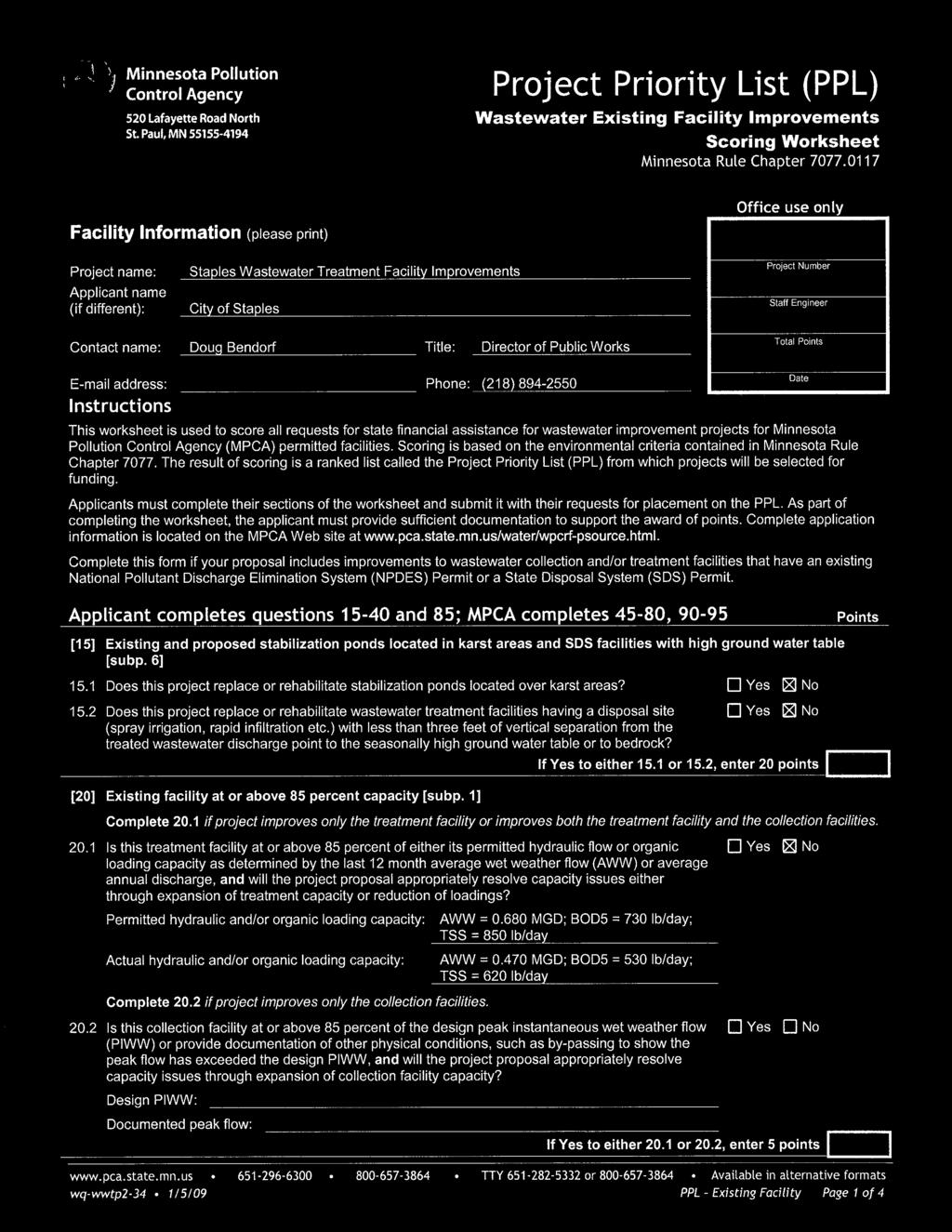
City of Staples, Minnesota
|
|
|
- Dwayne Montgomery
- 6 years ago
- Views:
Transcription
1 Wastewater Treatment Facility Plan November 2012 City of Staples, Minnesota Bolton & Menk kproject No. W
2
3
4
5 TABLE OF CONTENTS SECTION 1 INTRODUCTION A. Purpose B. Background SECTION 2 DESIGN CONDITIONS A. Planning Period B. Customer/User Projections Domestic and Commercial Projections C. Wastewater Flows D. Wastewater Loadings E. Biosolids F. Effluent Limits G. Reliability Criteria SECTION 3 EVALUATION OF EXISTING FACILITIES A. Treatment Facility B. Facility Condition Influent Lift Station Manually Cleaned Static Bar Screens Cyclone Grit Remover Trickling Filter Aeration Basins Final Clarifiers Return Sludge System Chlorine Contact Basin Aerobic Digesters Chemical Feed Systems Blowers Pumps and Piping Control Buildings Sludge Tanks SECTION 4 WASTEWATER TREATMENT FACILITY IMPROVEMENTS A. General Optimumization of Operation and/or Rehabilitation of Existing Facilities Regionalization Construction of a New Facility B. Wastewater Treatment Facility Improvements Alternative 1: Moderate Improvements to Optimize Current Processes Staples, MN W Wastewater Treatment Facility Plan Page TOC-i Prepared by Bolton & Menk, Inc.
6 2. Alternative 2: Rehabilitation of the Facility with the Addition of Flow Equalization Alternative 3: Rehabilitation of Facility with Addition of Extended Aeration Process C. Facility Classification SECTION 5 CONSTRUCTION COST ESTIMATE A. General B. Capital Costs C. Operational Costs D. Total Project Cost SECTION 6 RECOMMENDATION AND IMPLEMENTATION A. Recommendation B. Project Funding Bonding Assessment Rural Development (RD) Loan State Revolving Fund Loan (through the PFA) C. User Rates D. Implementation Schedule Appendix A Appendix B Appendix C Appendix D Appendix E LIST OF APPENDICES NPDES Permit Facility Plan Submittal Checklist and SERP Mailing List Public Hearing Presentation Material and Comments Resolution Adopting the Facility Plan PPL Application, Preliminary Project Scoring Worksheet, and Environmental Information Worksheet Staples, MN W Wastewater Treatment Facility Plan Page TOC-ii Prepared by Bolton & Menk, Inc.
7 LIST OF FIGURES Figure Number Page 2.1 Historical and Projected Populations City of Staples, Todd County, and Wadena County Historical Flow Data Staples WWTF Historical CBOD 5 and TSS Loading - Staples WWTF Existing Static Screens Static Screen Support Eutek Teacup Grit Removal System Trickling Filter Arm Trickling Filter Mechanism Bypass Pipe Leak Aeration Basin Splitter Box Aeration Basin Air Header Hoist Aeration Basin and Return Sludge Piping Older Clarifier Influent to Older Clarifier Newer Clarifier Chlorine Contact Basin Lime Feed System Aerobic Digesters Chlorine Enclosure Blowers LIST OF TABLES Table Number Page 2.1 Population Projections Average Daily Flows City of Staples Determination of Design Flows City of Staples Historical Influent Loadings City of Staples Design Wastewater Flows and Loading City of Staples Biosolids Land Applied City of Staples Effluent Limits City of Staples Staples Wastewater Treatment Facility Unit Process Summary Alternative 1: Moderate Improvements to Optimize Current Processes Alternative 2: Rehabilitation of Existing Facility with the Addition of: Flow Equalization Staples, MN W Wastewater Treatment Facility Plan Page TOC-iii Prepared by Bolton & Menk, Inc.
8 4.3 Alternative 3: Rehabilitation of Facility with Addition of Extended Aeration Process Capital Cost Estimates Operations & Maintenance Cost Changes City of Staples Total Annual Project Costs City of Staples Estimated User Rates City of Staples Project Implementation Schedule City of Staples Staples, MN W Wastewater Treatment Facility Plan Page TOC-iv Prepared by Bolton & Menk, Inc.
9 SECTION 1 INTRODUCTION A. PURPOSE This report provides the City of Staples, Minnesota with recommendations for wastewater facility improvements, including a prioritized list of items for repair or replacement. Recommendations are based on input from the City staff, a visual inspection of the infrastructure, and an evaluation of facility requirements in accordance with the current recommended practice. Section 2 provides a review of the current design conditions. An evaluation of the existing facility is provided in Section 3. Alternatives for wastewater treatment facility improvements are discussed in Section 4, with costs presented in Section 5 and the proposed project implementation in Section 6. B. BACKGROUND The Staples Wastewater Treatment Facility was originally constructed in 1965 and expanded in The aeration basins, two of the final clarifiers, the chlorine contact tank, and the aerobic digesters were originally constructed in A new pretreatment and control building, trickling filter and one final clarifier were added in In 1997, the City replaced the influent main lift station. Since 1991, the City has maintained the facility, replacing parts and rehabilitating pumps and equipment as necessary, but no significant rehabilitation or construction has been done on the facility itself. Overall, the existing system can be effective to treat the facility s proposed flows and loadings, but due to design deficiencies and the age of the system, it is not functioning at its full potential. The Facility s most recent National Pollution Discharge Elimination System (NPDES) Permit, which comes up for renewal every five years, requires that the City provide dechlorination and phosphorus removal at the facility by March 1,2013, in order to meet increased effluent quality standards implemented with this permit cycle. These two processes are the only required modifications at this time. Staples, MN W Page 1-1 Wastewater Treatment Facility Plan Prepared by Bolton & Menk, Inc.
10 Additionally, the City staff has noted that when there are high flows (typically in excess of 0.5 million gallons per day), the aeration basins and the final clarifier splitter box experience some overflow and vortex issues that are of concern. The City is interested in ways to remedy these issues, as well as recommendations for general rehabilitation or improvements necessary to allow the facility to operate appropriately over the next few permit cycles. Finally, the facility has limited biosolids digestion and storage capacity. MPCA regulations require sludge be stabilized before land application. Because of the limited capacity, the City of Staples has been required to use lime to stabilize the sludge prior to land application, which is year-round. This system is inefficient and potentially dangerous, as lime can be a very dangerous chemical if improperly stored or handled. Staples, MN W Page 1-2 Wastewater Treatment Facility Plan Prepared by Bolton & Menk, Inc.
11 SECTION 2 DESIGN CONDITIONS A. PLANNING PERIOD Wastewater treatment facilities are typically designed based on a 20-year planning period, as it is generally not feasible to make numerous changes in the capacity of a wastewater treatment facility. In addition, a 20-year planning period is required for the project to be eligible for funding assistance with the Public Facilities Authority (PFA). A design year of 2035 is used for this evaluation. Projected wastewater flows and loadings are determined using a combination of population trends and expected commercial and industrial growth. There are currently now significant industrial users in the City of Staples, though there is a nearby hospital that sends wastewater to the facility. As hospital waste is typically similar to domestic waste, all projections are based on typical domestic strength wastewater. B. CUSTOMER/USER PROJECTIONS 1. Domestic and Commercial Projections A number of methods are used to predict population trends, including a review of historical city and county population trends and various mathematical projections. A combination of methods is involved in projecting the future population. Table 2.1 summarizes the historical and projected populations for the City of Staples and Wadena and Todd Counties as reported by the Minnesota State Demographic Center. The City of Staples straddles the boundary line between the two counties. As shown in Table 2.1 and Figure 2.1, the projected population followed a decreasing trend from 2006 through 2010, but is projected to begin increasing through The Design population for the year 2035 for the City of Staples is 3,791 people. Staples, MN W Page 2-1 Wastewater Treatment Facility Plan Prepared by Bolton & Menk, Inc.
12 Table 2.1 Population Projections Year City of Staples Todd County Wadena County ,149 24,469 13, ,981 25,200 14, ,434 25,720 14, ,559 26,230 14, ,674 26,620 15, ,730 26,630 15, ,791 26,660 15,440 Source: Minnesota Office of Geographic and Demographic Analysis/State Demographic Center Staples, MN W Page 2-2 Wastewater Treatment Facility Plan Prepared by Bolton & Menk, Inc.
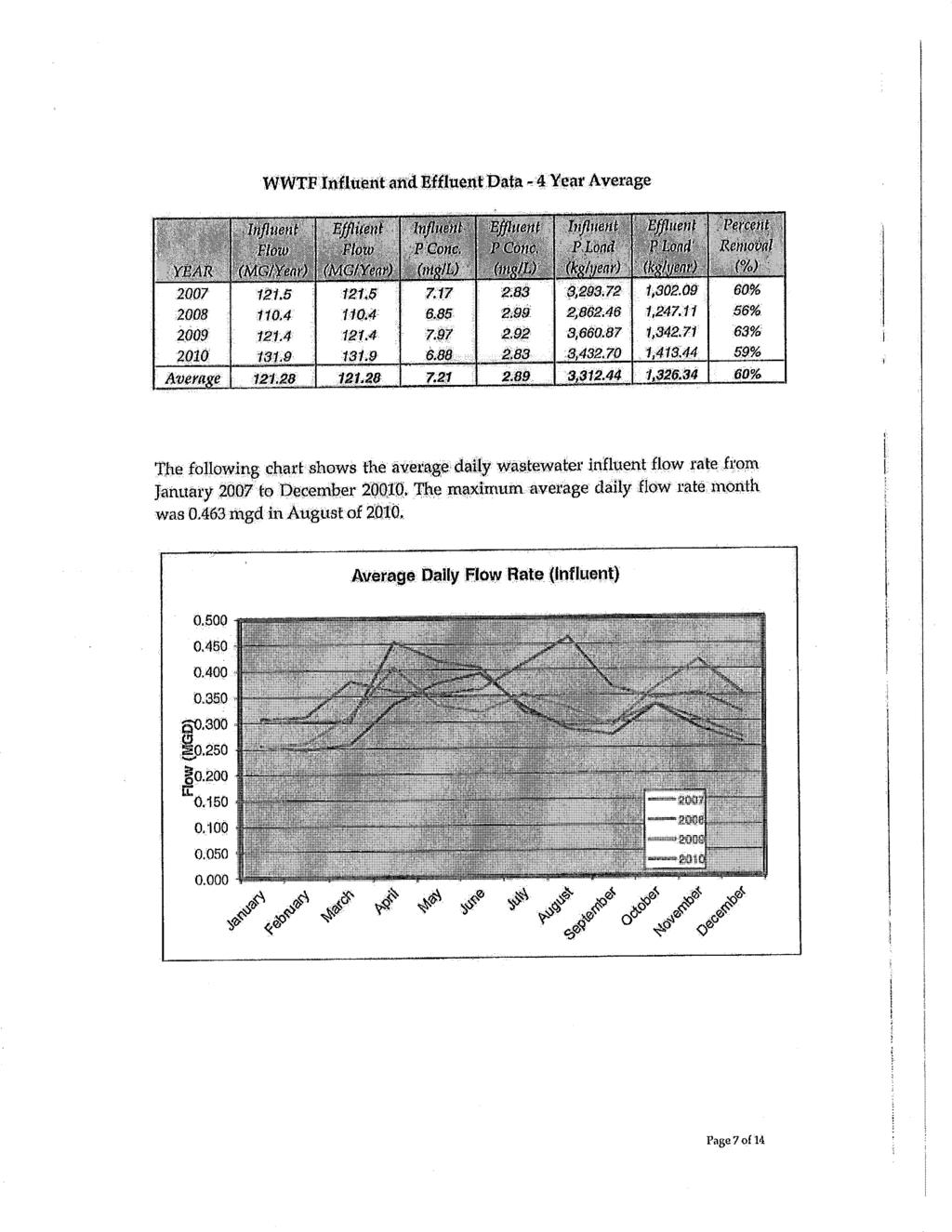
13 C. WASTEWATER FLOWS The City of Staples National Pollutant Discharge Elimination System (NPDES) Permit allows for an influent average wet weather (AWW) flow of 0.68 million gallons per day (MGD) and a peak flow of 1.3 MGD. A historical summary of the influent flows of the Staples Wastewater Treatment facility for the past ten years is presented in Table 2.2 and Figure 2.2. Staples, MN W Page 2-3 Wastewater Treatment Facility Plan Prepared by Bolton & Menk, Inc.
14 Table 2.2 Average Daily Flows - City of Staples Monthly Month Average (gpd) (gpd) (gpd) (gpd) (gpd) (gpd) (gpd) (gpd) (gpd) (gpd) (gpd) January 319, , , , , , , , , , ,168 February 308, , , , , , , , , , ,487 March 306, , , , , , , , , , ,103 April 366, , , , , , , , , , ,367 May 441, , , , , , , , , , ,177 June 500, , , , , , , , , ,853 July 612, , , , , , , , , ,723 August 414, , , , , , , , , ,418 September 343, , , , , , , , , ,985 October 330, , , , , , , , , ,504 November 320, , , , , , , , , ,020 December 316, , , , , , , , ,852 Yearly Average 381, , , , , , , , , ,195 Note: A blank space indicates a month where no flow data was available. Staples, MN W Page 2-4 Wastewater Treatment Facility Plan Prepared by Bolton & Menk, Inc.
15 The average daily flow peaks in the spring months each year, but the spring peaks are less than the permitted average wet weather flow. The maximum daily flow also peaks during the spring months and, in 2010 and 2011, exceeded the permitted AWW flow. These large fluctuations in influent flow to the treatment facility are attributed to infiltration and inflow (I/I). I/I flows are heavily influenced by seasonal and precipitation events and are present in essentially all gravity collection systems. The City of Staples is committing to an infiltration and inflow reduction program over the next few years in an effort to reduce these large fluctuations in flow. The Minnesota Pollution Control Agency (MPCA) has guidelines for determining flow projections. Future projections developed for different climactic conditions as described. The Average Dry Weather (ADW) flow is based on the flow with no inflow due to Staples, MN W Page 2-5 Wastewater Treatment Facility Plan Prepared by Bolton & Menk, Inc.
16 precipitation and/or snow melt and no infiltration due to high groundwater. The ADW flow typically occurs in winter months or in very dry summer months. This flow corresponds with water pumped from the drinking water source. The Average Wet Weather (AWW) flow, or peak month flow, is the daily average flow for the wettest 30 consecutive days for mechanical treatment systems such as Staples. AWW flow is based on flow with infiltration due to high groundwater and typical inflow due to precipitation and/or snowmelt. This flow usually occurs in spring and early summer. The Peak Hourly Wet Weather (PHWW) flow is the peak flow during the peak hour of the day at a time when the ground water is high and a five-year storm is occurring. The Peak Instantaneous Wet Weather (PIWW) flow is the peak instantaneous flow during the day at a time when the ground water is high and a twenty-five year onehour storm event is occurring. This flow is used for sizing pumps and piping systems. An MPCA Determination of Design Flows worksheet was prepared using historical wastewater treatment facility flow data from the past five years. This worksheet is presented in Table 2.3. Table 2.3 Determination of Design Flows - City of Staples A) For Determination of Peak Hourly Wet Weather Design Flow (PHWW) gpd 1 Present peak hourly dry weather flow 1,104,000 2 Present peak hourly flow during high ground water period (no runoff) 1,700,000 3 Present peak hourly dry weather flow [same as (1)] - 1,104,000 4 Present peak hourly infiltration = 596,000 Present hourly flow during high ground water period and runoff at point of 5 greatest distance between Curves Y and Z Present hourly flow during high ground water (no runoff) at same time of day as 6 (5) measurement - 7 Present peak hourly flow = 8 Present peak hourly inflow adjusted for a 5-year 1-hour rainfall event 199,000 9 Present peak hourly infiltration [same as (4)] 596, Peak hourly infiltration cost effective to eliminate Peak hourly infiltration after rehabilitation (where rehabilitation is cost effective) = 596, Present Peak hourly adjusted inflow [same as (8)] 199, Peak hourly inflow cost effective to eliminate - 0 Staples, MN W Page 2-6 Wastewater Treatment Facility Plan Prepared by Bolton & Menk, Inc.
17 14 Peak hourly inflow after rehabilitation (where rehabilitation is cost effective) = 199, Population increase _100_ gpcd times 2.5 (peaking factor) 0 16 Peak hourly flow from planned industrial increase 0 17 Estimated peak hourly flow from future unidentified industries 0 18 Peak hourly flow from other future increases 0 19 Peak hourly wet weather design flow [(1)+(11)+(14)+(15)+(16)+(17)+(18)] 1,899,000 For Determination of Peak Instantaneous Wet Weather Design Flow gpd B) (PIWW) 20 Peak hourly wet weather design flow [same as (19)] 1,899,000 Present peak hourly inflow adjusted for a 5-year 1-hour rainfall event [same as - 199, (8)] 22 Present peak inflow adjusted for a 25-year 1-hour rainfall event + 271, Peak instantaneous wet weather design flow = 1,971,000 C) For Determination of Average Dry Weather Design Flow (ADW) gpd 24 Present average dry weather flow 241, Population increase _100_ gpcd + 49, Average flow from planned industrial increase Estimated average flow from other future unidentified industries Average flow from other future increases Average dry weather design flow [(24)+(25)+(26)+(27)+(28)] = 290,400 D) For Determination of Average Wet Weather Design Flow (AWW) gpd 30 Present average dry weather flow 241, Average infiltration after rehabilitation (where rehabilitation is cost effective) + 292, Average inflow after rehabilitation (where rehabilitation is cost effective) + 97, Population increase _100_ gpcd + 49, Average flow from planned industrial increase Estimated average flow from future unidentified industries Average flow from other future increases Average wet weather design flow [(30)+(31)+(32)+(33)+(34)+(35)+(36)] = 680,000 The ADW flow determined by this worksheet is 0.29 MGD and the AWW flow is 0.68 MGD. These flows are similar to the existing design flows, which were determined in There are several reasons why the design flows from 1991 may match the current design flows, including conservative planning in Staples, MN W Page 2-7 Wastewater Treatment Facility Plan Prepared by Bolton & Menk, Inc.
18 D. WASTEWATER LOADINGS Pollutant loadings for the design year are required to size a wastewater treatment facility. Projected loadings are calculated by determining a pounds-per-capita-per-day (lb/capita/day) value for five-day carbonaceous biochemical oxygen demand (CBOD 5 ), total suspended solids (TSS), and phosphorus (P) and multiplying this value by the projected population. Historical loading rates and per-capita values for the City of Staples are presented in Table 2.4. Table 2.4 Historical Influent Loadings - City of Staples Parameter Population 3,146 3,131 3,099 2,981 2,976 CBOD 5 : Influent Load (lb/day) CBOD 5 : Per Capita Load (lb/day) TSS: Influent Load (lb/day) TSS: Per Capita Load (lb/day) Phosphorus: Influent Load (lb/day) Phosphorus: Per Capita Load (lb/day) Figure 2.3 presents a chart of the historical CBOD 5 and TSS loadings. Staples, MN W Page 2-8 Wastewater Treatment Facility Plan Prepared by Bolton & Menk, Inc.
19 The existing loadings have spiked over the permitted CBOD5 loading of 730 lb/day and the permitted TSS loading of 850 lb/day on a regular basis over the past ten years. The influent CBOD5 typically peaks during the spring months and exceeded the permitted and design values almost every year. Influent TSS follows the same trend. Design flows and loadings based on existing flows and loadings and anticipated additional flows were calculated based on the information provided above and the projected population and are presented in Table 2.5. Staples, MN W Page 2-9 Wastewater Treatment Facility Plan Prepared by Bolton & Menk, Inc.
20 Table 2.5 Design Wastewater Flows and Loadings - City of Staples Parameter Value Unit Design Year Design Population 3,791 persons Average Dry Weather (ADW) Flow MGD Average Wet Weather (AWW) Flow MGD Peak Hourly (PHWW) Flow 1.90 MGD Peak Instantaneous (PIWW) Flow 1.97 MGD Biochemical Oxygen Demand, Carbonaceous 5-day (CBOD 5 ) 730 lb/day Total Suspended Solids (TSS) 850 lb/day Total Phosphorus (P) 27 lb/day E. BIOSOLIDS Sludge produced by the biological process is either injected or surface-sprayed on agricultural land. The City of Staples has a contract with a local land-owner to allow biosolids to be spread on a year-round basis. Because of lack of capacity, the City is continuously using lime to stabilize the biosolids and then loading it out for land application. Table 2.6 below shows the amount of biosolids that was land-applied by the City over the past nine years. Table 2.6 Biosolids Land-Applied - City of Staples Year Amount Applied ,400 gallons ,200 gallons ,400 gallons ,400 gallons ,400 gallons ,200 gallons ,400 gallons ,400 gallons Average 787,700 gallons Staples, MN W Page 2-10 Wastewater Treatment Facility Plan Prepared by Bolton & Menk, Inc.
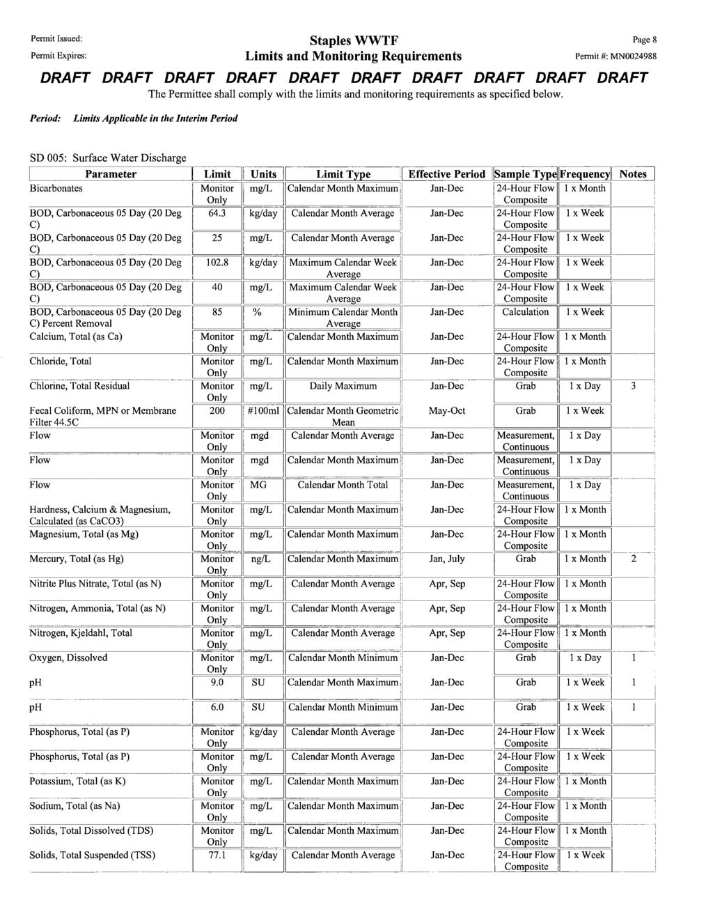
21 The existing aerobic digesters have a total volume of 152,000 gallons. The recommended amount of biosolids storage for any facility is at least 180 days to achieve appropriate stabilization and allow for a condensed period of land-application. Based on the above information, the City of Staples generates an average of 2,000 to 2,200 gallons of biosolids per day. With the addition of phosphorus removal, as required by the Facility s permit, there is estimated to be an additional 100 to 150 gallons of biosolids generated per day. Total biosolids generated per day is estimated to be approximately 2,300 gallons; therefore, in order to meet the recommendation of 180-days of storage, an additional 265,000 gallons of storage is required. F. EFFLUENT LIMITS Current effluent limits require a monthly average CBOD5 concentration of 25 mg/l or less and a TSS concentration of 30 mg/l or less. In addition, an 85% removal of CBOD5 and TSS is required. Projected effluent limits for CBOD5 and TSS are not anticipated to change in the next permit renewal cycle. The facility now also has a Phosphorus mass loading limit, which is new with the current permit cycle. Existing effluent limits are summarized in Table 2.7. Table 2.7 Effluent Limits - City of Staples Parameter Limit 5-Day CBOD 25 mg/l monthly, 85% Removal 40 mg/l max. calendar week average Dissolved Oxygen (DO) Monitor Only Fecal Coliform Bacteria (May - October) 200 organisms/100 ml Hardness, Calcium and Magnesium (as CaCO3) Monitor Only ph Total Kjeldahl Nitrogen (TKN) Monitor Only Total Phosphorous 939 kg/year (2070 lb/year) Total Residual Chlorine mg/l daily max. Total Suspended Solids (TSS) 30 mg/l monthly, 85% Removal 45 mg/l max. calendar week average Staples, MN W Page 2-11 Wastewater Treatment Facility Plan Prepared by Bolton & Menk, Inc.
22 G. RELIABILITY CRITERIA The MPCA provides recommended guidelines for process reliability. Due to design flows, the Staples Wastewater Treatment Facility should comply with Design Criteria A, which states: The following recommended guidelines apply to any treatment facility that: 1. is designed to receive less than an average wet weather flow of 100,000 gallons per day (gpd) and an average of 170 pounds BOD5 per day and has standard secondary effluent limitations and no ammonia nitrogen limitations; or 2. discharges to a class 7 stream and is designed to receive less than an average wet weather flow of 1,000,000 gpd and an average of 1,700 pounds BOD5 per day and has no ammonia - nitrogen limitations. Having a phosphorus limitation does not alter the applicability of a Design Criteria. Treatment facilities with initial loadings at the time of start-up of less than one-half design must provide reliability in accordance with Design Criteria B. 1. Duplication of major treatment units is not required. 2. There must be at least two clarifiers provided for the treatment facility. Therefore, if no primary clarifier or intermediate clarifier is provided, at least two final clarifiers are required. For fixed film rotating reactors, there must be a sufficient number of shafts such that with the largest shaft out of service, the remaining shafts will have at least 50 percent of the total required media surface area. If provided, duplication should, as a minimum, be in accordance with Design Criteria B. The Staples Wastewater Treatment Facility discharges to a Class 7 stream, is designed to receive an average wet weather flow of less than 1,000,000 gpd and an average BOD5 of less than 1,700 lb/day, and has no ammonia-nitrogen limitations. It therefore meets condition 2 of Design Criteria A. The facility has three final clarifiers and meets the reliability guidelines. Staples, MN W Page 2-12 Wastewater Treatment Facility Plan Prepared by Bolton & Menk, Inc.
23 SECTION 3 EVALUATION OF EXISTING FACILITIES A. TREATMENT FACILITY The existing wastewater treatment facility consists of an influent lift station, a manually cleaned static bar screen, a cyclone grit removal system, two 46,000-gallon aeration basins, three final clarifiers, a chlorine contact basin, and four 38,400-gallon biosolids digester tanks. This section reviews the treatment capacity for the various unit processes at the Staples WWTF based on current design recommendations. This review indicates that the existing facility is adequate to meet the proposed design average wet weather flow, but is undersized to meet the proposed peak flow of 1.9 MGD. Table 3.1 Staples WWTF Unit Process Summary Parameter Value Units Design Criteria AWW (MGD) Static Screens Number 2 PIWW each Bar Spacing Inches Volume 10 ft 3 /MG Grit Removal Number 1 centrifugal Maximum Available Capacity PWW (MGD) CBOD 5 (lb/day) system Unit Size 54 inch diameter 95% Capture Size 100 micron Grit volume 5 ft 3 /MG Trickling Filter Diameter 24 foot Area 452 ft 2 Depth 6 feet min 6 ft Peak Hydraulic Loading 1.99 gpm/ft BOD Loading 242 lb/1000 ft Aeration Basins Number 2 2+ Dimensions 20 x 35 feet Sidewater Depth 12 feet >10 ft and < 30 ft Volume 124,000 gallons Freeboard feet >1.5 ft Detention Time ADW Flow 10.2 hours AWW Flow 4.4 hours PHWW Flow 1.6 hours BOD Loading 30 lb/day/1000ft 3 <40 lb/day/1000 ft Staples, MN W Page 3-1 Wastewater Treatment Facility Plan Prepared by Bolton & Menk, Inc.
24 Influent Loading w/ 30% CBOD removal by trickling filter MLSS concentration 2500 mg/l 1,000-3,000 mg/l Solids Retention Time 8 days Final Clarifiers Number 3 Dimensions 12 x 35 feet Sidewater depth 2 units (1965) 8.5 feet min 12 ft 1 unit (1991) 10 feet min 12 ft Surface Area 1,260 ft 2 Surface Settling Rate ADW Flow 230 gpd/ft 2 AWW Flow 540 gpd/ft PHWW Flow 1,507 gpd/ft 2 <1,200 gpd/ft Weir Loading Rate ADW Flow 2,010 gpd/lf AWW Flow 4,720 gpd/lf 1.03 PHWW Flow 13,200 gpd/lf <20,000 gpd/lf 2.88 RAS Pumps Number Capacity 300 gpm % AWW Chlorine Contact Basin Number 1 Total Volume 11,100 gallons Detention Time ADW Flow 55 minutes AWW Flow 23.5 minutes PHWW flow 8.4 minutes >15 minutes 1.07 Aerobic Sludge Digesters Number 4 Dimensions 17 x 24 feet Depth 12.5 feet Total Volume 152,000 gallons B. FACILITY CONDITION The unit processes at the existing wastewater treatment facility range in condition from good to poor. Generally speaking, age appears to be a preliminary indicator of the structural condition. 1. Influent Lift Station The influent lift station was constructed in 1997 and has had regular maintenance over the past 15 years. The lift station consists of high lift pumps and a grinder to reduce the size of solids in the wastewater. The grinder pump was rehabilitated by the City in The lift station is in good condition and needs no improvements at this time. Staples, MN W Page 3-2 Wastewater Treatment Facility Plan Prepared by Bolton & Menk, Inc.

25 2. Manually Cleaned Static Bar Screens The static bar screens were installed in 1991 and are in good condition. The screens have been well maintained and the troughs were replaced recently. The screens are manually cleaned and the auger that removes the screenings is in need of a new gear box. The steel platform which supports the screens is in poor condition, showing significant rusting and degradation. The screenings dump from the trough directly into a dumpster on the level below. The screenings are not adequately dewatered and are taken to the landfill in a rather wet state. This situation may soon need to change as landfill or waste management regulations evolve. Figure 3.1: Existing Static Screen Staples, MN W Page 3-3 Wastewater Treatment Facility Plan Prepared by Bolton & Menk, Inc.

26 Figure 3.2: Static Screen Supports Staples, MN W Page 3-4 Wastewater Treatment Facility Plan Prepared by Bolton & Menk, Inc.

27 3. Cyclone Grit Remover Grit is removed with a Eutek Teacup cyclone grit removal system. The system was installed in 1991 and is in poor to fair condition. The exterior of the Teacup is showing large amounts of rusting and flaking. The unit operates effectively and grit is adequately removed and dewatered. Figure 3.3: Eutek Teacup Grit Removal System Staples, MN W Page 3-5 Wastewater Treatment Facility Plan Prepared by Bolton & Menk, Inc.

28 4. Trickling Filter The trickling filter is contained in a square room and has a motor actuated rotor and four trickling arms. The trickling filter has no recirculation feed. The rotor mechanism and granular media are original from The mechanism is rusting and the rotor arms have significant leaks at the end, as well as plugged openings along the arms. The typical lifespan of granular filter media is 20 years and the media has likely reached the end of its lifespan, though it has not been tested. The trickling filter bypass pipe leaks where it enters the effluent trough and minor repairs are needed. Figure 3.4: Trickling Filter Arm Staples, MN W Page 3-6 Wastewater Treatment Facility Plan Prepared by Bolton & Menk, Inc.

29 Figure 3.5 Trickling Filter Mechanism Staples, MN W Page 3-7 Wastewater Treatment Facility Plan Prepared by Bolton & Menk, Inc.

30 Figure 3.6: Bypass pipe leak 5. Aeration Basins The trickling filter is followed by a four-way splitter structure and two aeration basin (each has two influent flow locations). The basins were constructed in 1965 and the air piping are original to that construction. The basin is constructed for a modified step influent and short hydraulic and solids retention times. The existing basins appear to be in fair condition, though a full inspection cannot be completed until they are emptied and cleaned. The air piping, headers, and diffusers are in poor condition and should be replaced. Staples, MN W Page 3-8 Wastewater Treatment Facility Plan Prepared by Bolton & Menk, Inc.

31 Figure 3.7 Aeration Basin Splitter Box Staples, MN W Page 3-9 Wastewater Treatment Facility Plan Prepared by Bolton & Menk, Inc.


32 Figure 3.8: Aeration Basin Air Header Hoist Figure 3.9: Aeration Basin and Return Sludge Piping Staples, MN W Page 3-10 Wastewater Treatment Facility Plan Prepared by Bolton & Menk, Inc.

33 6. Final Clarifiers There are three rectangular final clarifiers. Two were constructed in 1965 and one in All three have their original arms and piping. Chains and sprockets were recently replaced on all three clarifiers. The motors were rebuilt and gearboxes replaced on the older clarifiers within the past five years. The clarifier structures are generally in good condition, but the arms, piping, slide gates and baffle walls are in poor condition for all three clarifiers. The splitter box leading to the clarifier has three slide gates, which do not work and therefore do not allow the City to isolate a clarifier, and has a tendency to overflow and unintentionally bypass the new clarifier in high flow situations. Figure 3.10 Older Clarifier Staples, MN W Page 3-11 Wastewater Treatment Facility Plan Prepared by Bolton & Menk, Inc.


34 Figure 3.11 Influent to Older Clarifier Figure 3.12: Newer Clarifier Staples, MN W Page 3-12 Wastewater Treatment Facility Plan Prepared by Bolton & Menk, Inc.
35 7. Return Sludge System The return activated sludge (RAS) system was constructed in 1965 and is in very poor condition. The RAS splitter box which divides the returned sludge between the two aeration basins is extremely rusted and in poor structural condition. Return sludge is pumped by two vertical centrifugal pumps which are an outdated model. The pumps are in need of rebuilding or replacement and parts are very difficult to find and can be expensive. 8. Chlorine Contact Basin The chlorine contact basin is a concrete structure constructed in The structure is in generally good condition, but the basin is inadequately sized for current and proposed peak flows. The tank has concrete baffle walls which are four feet apart. At the beginning of the chlorine contact tank is the draw for a heat exchange system that the City uses to provide heat to some of the Public Works buildings. Because this draw is after the chlorine injection point, the system can only be used during the winter months when the system is not being chlorinated. If the draw would be relocated to before the chlorine injection point, the system could be used year-round and provide both heating and cooling. Staples, MN W Page 3-13 Wastewater Treatment Facility Plan Prepared by Bolton & Menk, Inc.

36 Figure 3.13: Chlorine Contact Basin 9. Aerobic Digesters There are four rectangular aerobic digester tanks. Two structures were constructed in 1965 and two in The diffusers were all new in There is some moderate concrete repairs necessary on the interior of the basins. Staples, MN W Page 3-14 Wastewater Treatment Facility Plan Prepared by Bolton & Menk, Inc.

37 The capacity of the existing digesters equals approximately 50 days of sludge storage. Due to MPCA sludge stabilization requirements and the limited storage capacity, the City uses lime to stabilize the sludge prior to land-application. Because this was not intended in the original design, the City has a cobbledtogether lime stabilization process that is potentially dangerous and is not cost effective. Lime is added to one basin each week on average and the process is time consuming and expensive. Longer biosolids storage time would allow for the lime stabilization process to be eliminated. Figure 3.14 Lime Feed System Staples, MN W Page 3-15 Wastewater Treatment Facility Plan Prepared by Bolton & Menk, Inc.

38 Figure 3.15: Aerobic Digesters 10. Chemical Feed Systems The facility currently feeds chlorine and polymer, and is in the process of testing ferric chlorine feed on a plant-scale basis. In addition, by March 1, 2013, the City is required to add dechlorination and phosphorus removal systems to meet new effluent limits. i. Chlorine System The City feeds gas chlorine to the beginning of the chlorine contact tank and to the RAS influent. The chlorine system is in fair condition and can continue to be used. The chlorine system is currently stored in an open enclosure outside of the facility that does not provide adequate protection during the winter months. Beginning this year, the City is feeding chlorine to control filamentous on a year-round basis, and a weather-tight enclosure is necessary. Staples, MN W Page 3-16 Wastewater Treatment Facility Plan Prepared by Bolton & Menk, Inc.

39 Figure 3.16: Chlorine Enclosure ii. Polymer System The polymer system is located inside of the old control building and is in good condition. However, the system is not isolated from the other equipment in the room, particularly the heat exchanger, and does not have sufficient containment. The operators feel that the polymer pumps are not ideal for continuous use and would like to see them replaced. iii. Dechlorination There are several methods of chemical dechlorination that can be implemented at this facility to reduce chlorine residual in the effluent. Staples, MN W Page 3-17 Wastewater Treatment Facility Plan Prepared by Bolton & Menk, Inc.
40 Sulfur Dioxide The injection of sulfur dioxide (SO2) in gaseous form is a typical way of reducing total residual chlorine in wastewater treatment facility effluent. A sulfur dioxide system is nearly identical to the facility s existing chlorine system, which may make the implementation of this method easier for the staff. Through a series of chemical reactions, the sulfur dioxide will react with the free and combined chlorine residual and form chloride and sulfate ions. These reactions are nearly instantaneous and, as a result, the sulfur dioxide can be injected into the very end of the chlorine contact chamber. A baffle will be added to facilitate mixing of sulfur dioxide into the water. Adding this baffle will reduce the contact time in the existing chamber to 18.5 minutes at average wet weather flow and 9.6 minutes at peak flow. Sulfur dioxide injected at an appropriate feed rate can effectively and consistently reduce total chlorine residual to below permitted levels. A sulfur dioxide system will include a gas regulator, an automatic switchover system, cylinder scales, tubing, and a sulfur dioxide injection system, as well as a new baffle wall at the end of the chlorine contact tank. Sodium Bisulfite Chlorine residual can also be reduced by the injection of liquid sodium bisulfite (NaHSO3). Sodium bisulfite will react with the free and combined chlorine residual and form chloride ions, ammonia and sodium bisulfate. These reactions are also nearly instantaneous and the sodium bisulfite can be injected into the end of the existing chlorine contact chamber. A baffle will be added to facilitate mixing of sodium bisulfite into the water. Adding this baffle will reduce the contact time in the existing chamber to 18.5 minutes at average wet weather flow and 9.6 minutes at peak flow. Sodium bisulfite injected at an appropriate feed rate can effectively and consistently reduce total chlorine residual to below permitted levels. A sodium bisulfite chemical feed system will include a chemical tank and containment, a chemical feed pump, tubing, and an injection port, as well as Staples, MN W Page 3-18 Wastewater Treatment Facility Plan Prepared by Bolton & Menk, Inc.

41 a new baffle wall at the end of the chlorine contact tank. Since sodium bisulfite in solution freezes at approximately 45 degrees Fahrenheit, a weatherproof shelter with heating system is also required. iv. Phosphorus Removal The City has recently tested a ferric chloride system for use in phosphorus removal. Based on the results of the plant-scale testing, the ferric chloride will be effective at removing phosphorus and a feed system should be installed. A permanent ferric chloride feed system will include feed pumps, piping, a 2,000 gallon chemical tank and adequate secondary containment. 11. Blowers There are three positive displacement blowers located in the basement of the old control building. These blowers provide air for the aeration basin diffusers and the aerobic digester diffusers. The blowers were installed in 1991 and have been partially submerged in water and repaired several times since then. They are considered to be at the end of their useful lives. Figure 3.17 Blowers Staples, MN W Page 3-19 Wastewater Treatment Facility Plan Prepared by Bolton & Menk, Inc.
42 12. Pumps and Piping There are six pumps throughout the facility: two RAS pumps, two scum pumps, and two sludge loadout pumps. The six pumps are identical vertical centrifugal pumps four of which were installed in 1967 and two in They have all been rebuilt several times and are an outdated model that is very difficult to find parts for. In general the piping and valves throughout the facility are in fair condition. There are several valves that will likely need to be replaced through this project. 13. Control Buildings There are two controls buildings at this facility. The old control building was originally constructed in 1965 and is now used for secondary uses. The main floor contains the heat exchanger, the polymer system, and the electrical panel for the equipment installed in The basement contains the blowers, pumps and piping, and pressure filter for facility water. The new control building was constructed in 1991 and contains the pretreatment units and trickling filter, the electrical system for all of the equipment installed in 1991, and the office. The old control building is in poor condition and is not being fully utilized. The new control building is in good condition and generally needs little repair work. 14. Sludge Tanks The City has a 1,600 gallon sludge tanker truck that is used year-round for sludge loading and land-application. It is the opinion of the operators that the truck has reached its useful life and is in need of replacement. Because the truck is stored in the basement of the control building, wastewater fumes have cause d the electrical system to degrade and need replacement several times. In additional, the operators feel that a larger capacity truck would allow them to be more efficient at loading and land-application. Staples, MN W Page 3-20 Wastewater Treatment Facility Plan Prepared by Bolton & Menk, Inc.
43 SECTION 4 WASTEWATER TREATMENT FACILITY IMPROVEMENTS A. GENERAL In the following paragraphs, several categories of alternatives are given general consideration. Alternative solutions include: 1) optimization of operation and/or rehabilitation of existing facilities, 2) regionalization, or 3) construction of a new facility. 1. Optimumization of Operation and/or Rehabilitation of Existing Facilities The existing facility has maintained adequate treatment to meeting effluent requirements. However, the facility s proposed peak flow is higher than the current design peak flow. The existing system can be rehabilitated and improved to provide required capacity and ensure future effluent quality remains adequate. 2. Regionalization This category includes the possibility of diverting wastewater from the City to the wastewater treatment facility of a nearby community. A lift station with large pumps and a significant length of forcemain is typically required for regionalization, along with the demolition or mothballing of the existing treatment facility. The flows from the City of Staples are quite large and regionalization for this quantity of wastewater would be very difficult. Due to the distance and costs associated with regionalization in comparison to the magnitude of the required facility improvements, regionalization was not considered feasible at this time. 3. Construction of a New Facility The current facility is a mechanical treatment facility with continuous discharge. The current treatment processes are adequate to meet effluent limits. Construction of a new mechanical facility would require the demolition of the existing facility and the construction of a new facility, which would contain similar processes to the existing one. The costs for such an endeavor would be nearly twice the costs Staples, MN W Page 4-1 Wastewater Treatment Facility Plan Prepared by Bolton & Menk, Inc.
44 of rehabilitating the existing facility for a similar final result. As a result, construction of a new facility was not considered feasible at this time. B. WASTEWATER TREATMENT FACILITY IMPROVEMENTS At this time, it is not feasible to abandon the existing facility and construct a new facility, as most of the unit processes are in good condition and can be utilized to meet future design flows and loadings. The recommended improvements discussed in this section are based on optimization and rehabilitation of the existing facility. There are three alternatives discussed: Alternative 1: Moderate Improvements to Optimize Current Processes Alternative 2: Rehabilitation of Facility with Addition of Flow Equalization Alternative 3: Rehabilitation of Facility with Addition of Extended Aeration Process 1. Alternative 1: Moderate Improvements to Optimize Current Processes Alternative 1 includes a significant rehabilitation of all existing unit processes and modification of the chlorine contact basin to increase length-to-width ration. In addition, it includes constructing a new return activated sludge (RAS) system, and provided adequate containment for chemical feed systems. Table 4.1 presents a summary of the recommended improvements, based on the condition of the processes described above in Section 3. Staples, MN W Page 4-2 Wastewater Treatment Facility Plan Prepared by Bolton & Menk, Inc.
45 Table 4.1 Alternative 1: Moderate Improvements to Optimize Current Processes Pretreatment Rebuild static screen gear boxes Construct new static screen support structure Install screenings/dewatering press Replace centrifugal grit removal system Trickling Filtration Replace trickling filter drive and arms Replace media Install recirculation pipe/pumps Install bypass pipe to bypass portion of flow to filter Aeration Replace fine bubble diffusers and air piping Replace RAS system Replace the blowers Raise the elevation of the wall at the effluent end of the basins Final Clarification Replace piping and mechanism parts as required Add baffle walls to prevent short-circuiting Disinfection Remove existing baffle walls and install new fiberglass baffle walls 2 apart from each other Install sulfur dioxide system for dechlorination Biosolids Storage and Handling Construct a 265,000 gallon biosolids holding tank Modify loadout piping to accommodate new tank Provide exterior loadout area Chemical Phosphorus Removal Install ferric chloride feed system for phosphorus removal Other Chemical Feed Systems Rehabilitate existing old control building into chemical building with rooms for ferric chloride, polymer, chlorine, and sulfur dioxide or sodium bisulfate Pumps and piping Rehabilitate RAS, scum, and sludge loadout pumps as needed Provide a recirculation pump for the trickling filter Replace some valves and piping throughout the facility as needed Control Building None Miscellaneous Repair or rehabilitate steel building over aeration/biosolids storage area as necessary Alternative 1 allows the City to continue to use the processes that the operators are familiar with, rehabilitates equipment that is in poor condition, and provides dedicated and safe spaces for all chemicals. It provides dechlorination and phosphorus removal systems as required by the Facility s most recent NPDES permit. Staples, MN W Page 4-3 Wastewater Treatment Facility Plan Prepared by Bolton & Menk, Inc.
46 Alternative 1 does not include any improvements that would allow the facility to operate more efficiently under current peak flow events or meet the proposed peak flows. However, the City intends to research and implement an infiltration and inflow reduction program and hopes to eliminate a portion of those peak flows. Replacing the chlorine contact tank baffle walls with fiberglass baffles only 2-feet apart will increase the contact time in the basin to approximately 21 minutes at the existing peak flow of 1.3 MGD and to 14.5 minutes at the proposed peak flow of 1.9 MGD. 2. Alternative 2: Rehabilitation of the Facility with the Addition of Flow Equalization Alternative 2 includes moderate to extensive rehabilitation of the pretreatment processes, the trickling filter, and the existing aeration basin, as well as construction of a flow equalization basin, two new final clarifiers, and a new chlorine contact chamber. A summary of these recommendations is provided in Table 4.2 below. Table 4.2 Alternative 2: Rehabilitation of Existing Facility with the Addition of Flow Equalization Pretreatment Rebuild static screen gear boxes Construct new static screen support structure Install screenings/dewatering press Replace centrifugal grit removal system Trickling Filtration Replace trickling filter drive and arms Replace media Install recirculation pipe/pumps Install bypass pipe to bypass portion of flow to filter Aeration Replace fine bubble diffusers and air Replace RAS system Replace the blowers Raise the elevation of the wall at the effluent end of the basins Final Clarification Construct two new 35-foot diameter circular final clarifiers Provide automatic wasting Disinfection Construct new chlorine contact basin Install sulfur dioxide or sodium bisulfite system for total chlorine residual reduction Staples, MN W Page 4-4 Wastewater Treatment Facility Plan Prepared by Bolton & Menk, Inc.
47 Flow Equalization Construct a 1.0 million gallon flow equalization basin (75- foot diameter, 30-foot depth) and associated piping Biosolids Storage and Handling Convert the existing final clarifiers and chlorine contact chamber into additional biosolids storage (add approximately 100,000 gallons or 40 additional days of storage) Replace the coarse bubble diffusers in the existing storage tanks Extend sludge loadout piping out of garage so that loading into a larger tank is possible Potentially replace existing tank truck with larger truck or tractor and tank combination Chemical Phosphorus Removal Install ferric chloride feed system for phosphorus removal Other Chemical Feed Systems Rehabilitate existing old control building into chemical building with rooms for ferric chloride, polymer, chlorine, and sulfur dioxide or sodium bisulfate Pumps and piping Replace RAS, scum, and sludge loadout pumps Provide a recirculation pump for the trickling filter Replace valves and piping throughout the facility as needed Control Building Rehabilitate existing MCCs, including consolidating both MCC units in the new control building Repair or replace building HVAC as required Miscellaneous Repair or rehabilitate steel building over aeration/biosolids storage area as necessary Alternative 2 allows the City to continue using the existing processes that the operators are familiar with and provides flow equalization, dedicated and safe spaces for all chemicals, and rehabilitates or replaces equipment in poor condition. It provides dechlorination and phosphorus removal systems as required by the Facility s most recent NPDES permit. This alternative provides new final clarifiers which will allow the facility to easily handle current and proposed peak flows and a new chlorine contact tank that has adequate chlorine contact time and sufficient space for dechlorination. It also provides some additional biosolids storage, though it may not provide enough holding time to complete eliminate the lime stabilization process. Other aspects to consider include the fact that the proposed flow equalization basin is quite large for the property and the improvements only provide 100 days of sludge storage, while 180 days is recommended. Staples, MN W Page 4-5 Wastewater Treatment Facility Plan Prepared by Bolton & Menk, Inc.
48 3. Alternative 3: Rehabilitation of Facility with Addition of Extended Aeration Process Alternative 3 includes rehabilitation of the pretreatment processes and the trickling filter, as well as construction of an activated sludge process and a new chlorine contact chamber. A summary of the recommendations for this alternative can be seen below in Table 4.3. Table 4.3 Alternative 3: Rehabilitation of Facility with Addition of Extended Aeration Process Pretreatment Rebuild static screen gear boxes Construct new static screen support structure Install screenings/dewatering press Replace centrifugal grit removal system Trickling Filtration Replace trickling filter drive and arms Replace media Install recirculation pipe/pumps Install bypass pipe to bypass portion of flow to filter Aeration Construct three chamber concrete aeration basin with a hydraulic retention time of 18 hours Final Clarification Construct two new 35-foot diameter circular final clarifiers Provide automatic wasting Disinfection Construct new chlorine contact basin Install sulfur dioxide or sodium bisulfite system for total chlorine residual reduction Biosolids Storage and Handling Convert the existing aeration basin, final clarifiers and chlorine contact chamber into additional biosolids storage Replace the coarse bubble diffusers in the existing storage tanks and install coarse bubble diffusers in the existing aeration basin (for use in biosolids storage) Extend sludge loadout piping out of garage so that loading into a larger tank is possible Potentially replace existing tank truck with larger truck or tractor and tank combination Chemical Phosphorus Removal Install ferric chloride feed system for phosphorus removal Other Chemical Feed Systems Rehabilitate existing old control building into chemical building with rooms for ferric chloride, polymer, chlorine, and sulfur dioxide or sodium bisulfite Pumps and piping Replace RAS, scum, and sludge loadout pumps Provide a recirculation pump for the trickling filter Replace valves and piping throughout the facility as needed Staples, MN W Page 4-6 Wastewater Treatment Facility Plan Prepared by Bolton & Menk, Inc.
49 Control Building Rehabilitate existing MCCs, including consolidating both MCC units in the new control building Install electrical as necessary for new process equipment Repair or replace building HVAC as required Miscellaneous Repair or rehabilitate steel building over biosolids storage area as necessary Alternative 3 provides rehabilitated and new process equipment for the entire facility, does not require flow equalization, and provides additional biosolids storage space. It also provides dechlorination and phosphorus removal systems as required by the Facility s most recent NPDES permit. With the additional sludge storage space, there will be approximately 150 days of sludge storage. As a result, the biosolids will have time to thicken and will potentially be able to meet required standards without the addition of lime stabilization. However, this alternative does not provide 180 days of sludge storage as recommended and will require the operators to learn and operate a new treatment process. C. FACILITY CLASSIFICATION The MPCA classifies wastewater treatment facilities with a points system based on population, effluent limits, and treatment processes. The City of Staples WWTF is currently classified as a Class B facility. With the inclusion of a phosphorus effluent limit on the City s NPDES permit, the points value of the Facility s existing classification is at the very top of the Class B range. Alternative 1 will likely not add points to the Facility s classification, allowing it to remain a Class B facility. Alternatives 2 and 3 will add enough points for the Facility to be reclassified as a Class A facility. A change in facility classification may potentially require a new operator or an existing operator to achieve a new license status. Staples, MN W Page 4-7 Wastewater Treatment Facility Plan Prepared by Bolton & Menk, Inc.
50
51 SECTION 5 CONSTRUCTION COST ESTIMATE A. GENERAL Published and unpublished data on costs for similar kinds of construction were utilized to prepare the preliminary construction cost estimates presented below. Annual inflation rates for this type of construction have ranged from approximately 4 percent to 6 percent in recent years. The cost estimates presented are intended for use as a guideline in the decision process. Once preparation of final drawings and specifications is underway, the cost estimates can be refined. B. CAPITAL COSTS The estimated capital costs for the recommended improvements are presented in Table 5.1. As shown on the itemized preliminary cost estimate, engineering, construction observation, and administration are included. Table 5.1 Capital Cost Estimates Item Alternative 1 Alternative 2 Alternative 3 Mobilization, Bonds, and Insurance $ 150,000 $ 300,000 $ 300,000 Flow Equalization Basin N/A $ 800,000 N/A Static Screen $ 60,000 $ 60,000 $ 60,000 Screenings Dewatering Press $ 70,000 $ 70,000 $ 70,000 Grit Removal $ 100,000 $ 100,000 $ 100,000 Trickling Filter $ 200,000 $ 200,000 $ 200,000 Aeration Basin (including concrete, diffusers, and piping) $ 60,000 $ 60,000 $ 500,000 Blowers $ 65,000 $ 65,000 $ 65,000 RAS System $ 100,000 $ 100,000 $ 100,000 Final Clarifiers $ 125,000 $ 500,000 $ 500,000 Chlorine Contact Basin $ 50,000 $ 150,000 $ 150,000 Dechlorination System $ 25,000 $ 25,000 $ 25,000 Ferric Chloride System $ 50,000 $ 50,000 $ 50,000 Biosolids Storage $ 250,000 $ 200,000 $ 350,000 Biosolids Handling $ 150,000 $ 100,000 $ 100,000 "Old" Control Building/Other Chemical Feed Systems $ 150,000 $ 150,000 $ 150,000 Pumps and Piping $ 100,000 $ 250,000 $ 300,000 Electrical and Controls $ 350,000 $ 450,000 $ 450,000 HVAC $ 50,000 $ 150,000 $ 150,000 Sludge Tanker N/A $ 150,000 $ 150,000 Subtotal $ 2,105,000 $ 3,930,000 $ 3,770,000 Contingencies $ 210,000 $ 393,000 $ 377,000 Engineering, Administration, and Legal $ 350,000 $ 650,000 $ 622,000 Total $ 2,665,000 $ 4,973,000 $ 4,769,000 Staples, MN W Page 5-1 Wastewater Treatment Facility Plan Prepared by Bolton & Menk, Inc.
52 C. OPERATIONAL COSTS The estimated annual operational costs include labor, utilities, chemicals and other noncapital related expenditures. Because exact operational costs were not known, these costs are estimated based on experience with other facilities and knowledge of chemical and other costs. Table 5.2 below shows the estimated operational costs changes from the facility s existing operational costs. Table 5.2 Operations & Maintenance Cost Changes - City of Staples Item Alternative 1 Alternative 2 Alternative 3 Electric Utilities $ - $ 5,000 $ 5,000 Chemical Costs (Dechlorination/Ferric Chloride) $ 120,000 $ 120,000 $ 120,000 Total O&M Cost Adjustment $ 120,000 $ 125,000 $ 125,000 D. TOTAL PROJECT COST Based on project financing for 20-years at 3 percent annual interest, the total annual project costs are summarized in Table 5.3. Table 5.3 Total Annual Project Costs - City of Staples Alternative 1 Alternative 2 Alternative 3 Total Capital Cost $ 2,665,000 $ 4,973,000 $ 4,769,000 Annual Capital Cost $ 179,100 $ 334,300 $ 320,600 O&M Cost Adjustment $ 120,000 $ 125,000 $ 125,000 Total Annual Project Cost $ 299,100 $ 459,300 $ 445,600 Costs are annualized with a 3% rate over a 20 year period. Staples, MN W Page 5-2 Wastewater Treatment Facility Plan Prepared by Bolton & Menk, Inc.
53 SECTION 6 RECOMMENDATION AND IMPLEMENTATION A. RECOMMENDATION During discussions with the City s Public Works staff, it was indicated that, if possible, the City would prefer a moderate rehabilitation option that would enable the facility to operate effectively and within permit requirements for the next 10 to 15 years, when a further, large-scale rehabilitation project would be pursued. Based on this indication, plus the design flows and loadings and existing plant condition, it is recommended that the City pursue Alternative 1: Moderate Improvements to Optimize Current Processes. This alternative will provide the City with effective treatment, rehabilitated existing processes, and sufficient biosolids storage to meet recommendations. This alternative does not increase the flow capacity of any of the treatment processes, so it will not allow the facility to meet the proposed design flows for 2035, but should continue to be able to meet the current average and peak flows for the next 10 years, particularly should the City pursue infiltration and inflow reduction projects. No preliminary effluent limits were requested of the MPCA because the recommended alternative does not change the existing treatment processes, except in a way to meet new phosphorus and chlorine residual limits as implemented in the Facility s 2012 NPDES permit. B. PROJECT FUNDING There are several alternatives that the City can consider for project funding. 1. Bonding The City could sell general obligation, local improvement, or revenue bonds in order to raise the capital costs to improve the treatment facility. The proceeds of the bonds would need to be repaid, either through property taxes, assessments, or user charges to the system. 2. Assessment A portion of the capital costs of the project can be assessed to local property owners under Minnesota Statute 429. Using this method, a one-time assessment could be levied and repaid over a period of 10 to 20 years. This cost could help offset some monthly increases in user fees and permit use of general obligation bonding. Staples, MN W Page 6-1 Wastewater Treatment Facility Plan Prepared by Bolton & Menk, Inc.
54 3. Rural Development (RD) Loan The City may be eligible to secure a loan or grant through Rural Development for the wastewater improvements. Repayment could be through an increase in local property tax rates, user fees or assessments. A portion of the project costs may be eligible for grant funding as a part of this program depending on the economic status of the residents of the City. In order to be considered for Rural Development monies, a Preliminary Engineering Report (PER) must be completed and submitted to RD. This provides specific treatment and financial information for RD to consider. Rural Development uses an Equivalent Dwelling Unit (EDU) calculation for assisting in determining the amount and type of funding for which a community is eligible. The preliminary EDU calculations for the City of Staples indicate that it is unlikely the project would be eligible for grant financing, but loan financing may still be available. The PER would provide more specific information on the City s eligibility. 4. State Revolving Fund Loan (through the PFA) The loan program was created under the State Revolving Fund (SRF) provisions in the Federal Clean Water Act to provide financial assistance for water pollution control projects. Minnesota s revolving loan program provides loans to municipalities for planning, design and construction of wastewater treatment projects. The loans are typically for a 20-year period at an interest rate of two to four percent. The loan monies are administered through the Public Facilities Authority. To be eligible for PFA funding, the City must submit this Facilities Plan for review and approval by the Minnesota Pollution Control Agency. Revenue for loan repayment is typically generated by user rates, availability charges or assessment. C. USER RATES An increase in user rates will likely be necessary to finance the proposed treatments, unless the City has a significant amount of money in wastewater reserves or has recently raised user rates to account for an upcoming improvements project. The current Staples, MN W Page 6-2 Wastewater Treatment Facility Plan Prepared by Bolton & Menk, Inc.
55 wastewater users rates are $2.68 per 100 cubic feet of drinking water plus a monthly base rate of $11 per connection. Revenue generation is estimated based on 1,043 connections. See Table 6.1 for estimated user rates for each alternative (based on the annual costs presented in Table 5.3). These rates assume that the user rate must include the operations costs for the existing system, as well as the increased O & M costs with the recommended changes. Table 6.1 Estimated User Rates City of Staples Base Rate Cost/100 cubic feet Average Bill (500 cubic feet)) Current $11.00 $2.68 $24.40 Alternative 1 $13.00 $3.18 $28.90 Alternative 2 $18.00 $4.74 $41.70 Alternative 3 $18.00 $4.52 $40.60 D. IMPLEMENTATION SCHEDULE The Facility s recent NPDES permit requires that dechlorination and phosphorus removal be implemented by March 1, However, in discussions with the MPCA, it was indicated that the MPCA may be open to delaying the requirement for dechlorination if it is part of a larger construction project that requires planning, design, and funding. Alternative 1 is such a case, so dechlorination is proposed to be implemented with the full construction project. However, the phosphorus limit will remain and that portion of the project will still need to be implemented by March 1, The proposed implementation schedule for the wastewater treatment facility improvements is presented in Table 6.2. Staples, MN W Page 6-3 Wastewater Treatment Facility Plan Prepared by Bolton & Menk, Inc.
56 Table 6.2 Project Implementation Schedule - City of Staples Item Date City approves concept of wastewater treatment alternative November 2012 Submit a Facility Plan to MPCA December 1, 2012 MPCA reviews and approves Facility Plan Dec Feb 2013 City installs Ferric Chloride Feed Equipment February 2013 City requests placement on the 2014 IUP June 2013 Prepare plans and specifications Summer/Fall 2013 City receives notification of placement on 2014 IUP and funding programs September 2013 MPCA reviews and approves plans and specifications Fall/Winter 2013 Advertise, bid and award construction contract Winter 2013/2014 Initiate construction Spring 2014 Staples, MN W Page 6-4 Wastewater Treatment Facility Plan Prepared by Bolton & Menk, Inc.
57
58
59
60
61
62
63
64
65
66


67
68
69
70
71
72
73
74
75
76
77
78
79
80
81
82
83
84
85
86
87
88
89
90
91
92
93
94
95
96
97
98
99
100
101
102
103
104
105
106
107
108
109
110
111
112
113
114
115
116
117
118

119
120
121
122
123
124
125
126
127
128
129
130
131
132
133
134

135
136
137
138


139
Wastewater Treatment Facility Plan City of Silver Bay, Minnesota
 March 2017 Wastewater Treatment Facility Plan City of Silver Bay, Minnesota Project Number M25.113173 Prepared by: Bolton & Menk, Inc. 7533 Sunwood Dr. NW Ramsey, MN 55303 P: 763-433-2851 F: 763-427-0833
City of Elk River Wastewater Treatment Facility Improvements. Achieving Wastewater Treatment Goals
 City of Elk River Wastewater Treatment Facility Improvements Achieving Wastewater Treatment Goals By Tejpal Bala, P.E. Bolton & Menk, Inc. The City of Elk River received a new NPDES permit and the existing
Wastewater Facility Plan City of Marshall, Minnesota
 Wastewater Facility Plan City of Marshall, Minnesota Public Hearing March 14, 2017 Bolton & Menk, Inc. Project No. T22.108560 Glossary of General Terms & Abbreviations MPCA - Minnesota Pollution Control
Watertown Wastewater Facility Plan. August 11, 2015
 Watertown Wastewater Facility Plan August 11, 2015 Watertown Wastewater Wastewater Treatment Facility History Comprehensive Planning Wastewater Concerns Capacity Condition Permitting Requirements Watertown
SETTLING REVIEW CHECKLIST
 SETTLING REVIEW CHECKLIST Water Quality Wastewater Technical Review and Guidance FACILITY NAME CONSULTING ENGINEER DATE Water/Wastewater/#5.73, May 2001 SITE INSPECTION (DATE & INSPECTOR) PLANNING OR DESIGN
Assuming 100 gallons per capita per day, and 3 people per REU, design flows for the development are proposed to be:
 Andelina Farms Wastewater Treatment Plant Preliminary Basis of Design May 2018 Andelina Farms is a proposed Planned Unit Development in Saline Township located along US-12 just west of the City of Saline.
North Side WRP Master Plan Research and Development Department 2006 Seminar Series October 27, 2006 Metropolitan Water Reclamation District of
 North Side WRP Master Plan Research and Development Department 2006 Seminar Series October 27, 2006 Metropolitan Water Reclamation District of Greater Chicago Today s Goals Discuss project background Provide
ATTACHMENT 1 GENERAL FACILITY INFORMATION. BOD5 mg/l mg/l TSS mg/l mg/l NH3-N mg/l mg/l
 ATTACHMENT 1 GENERAL FACILITY INFORMATION 1. Facility Name: 2. Type of Facility: 3. Population Served: Present: Design: 4. Flow: Average Maximum Peak 5. Water Quality: Present Design Assumed Actual Source:
Lagoons Operation and Management in New Brunswick
 Lagoons Operation and Management in New Brunswick Lagoons Provide secondary treatment to domestic wastewater by the action of bacteria stabilizing the organic matter in the wastewater. Benefits of lagoons:
Minnesota Pollution Control Agency
 Minnesota Pollution Control Agency STATE OF MINNESOTA Minnesota Pollution Control Agency MUNICIPAL DIVISION PUBLIC NOTICE OF INTENT TO REISSUE NATIONAL POLLUTANT DISCHARGE ELIMINATION SYSTEM (NPDES)/ STATE
TABLE OF CONTENTS. SECTION 1 INTRODUCTION 1.1 Background Purpose and Scope
 TABLE OF CONTENTS Page EXECUTIVE SUMMARY... ES-1 SECTION 1 INTRODUCTION 1.1 Background... 1-1 1.2 Purpose and Scope... 1-2 SECTION 2 HYDRAULIC AND PROCESS ASSESSMENT 2.1 Data Gathering and Analysis...
DRAFT SUBMITTED TO: TOWNSHIP OF LONG HILL PREPARED BY: KLEINFELDER
 LONG HILL TOWNSHIP WASTEWATER TREATMENT PLANT CAPACITY ASSURANCE REPORT UPDATE DRAFT SUBMITTED TO: TOWNSHIP OF LONG HILL PREPARED BY: KLEINFELDER FEBRUARY 2018 LONG HILL TOWNSHIP WASTEWATER TREATMENT PLANT
SMCSD Headworks, Primary and Secondary Treatment Pre-Design
 Technical Memorandum SMCSD Headworks, Primary and Secondary Treatment Pre-Design Water andenvironment Subject: Prepared For: Prepared by: Reviewed by: SMCSD Mark Takemoto, Dennis Gellerman Steve Clary
Inland Empire Utilities Agency Carollo Engineers, Inc. CH2M HILL
 TECHNICAL MEMORANDUM IEUA Wastewater Facilities Master Plan TM 8 CCWRF Future Plans PREPARED FOR: PREPARED BY: REVIEWED BY: Inland Empire Utilities Agency Carollo Engineers, Inc. CH2M HILL DATE: October
Client: City of Pontiac Project Name: Regional WWTP Feasibility Location: Pontiac, MI Project Number: Issue Date: October 23, 2006
 Client: City of Pontiac Project Name: Regional WWTP Feasibility Location: Pontiac, MI Project Number: 13649553 Issue Date: October 23, 2006 Subject: WWTP Condition Assessment Auburn Plant 1. Grit Removal:
WEFTEC.06. **Cobb County Water System, Marietta, Georgia
 CHEMICALLY ENHANCED PRIMARY TREATMENT FOR A LARGE WATER RECLAMATION FACILITY ON A CONSTRICTED SITE - CONSIDERATIONS FOR DESIGN, START-UP, AND OPERATION ABSTRACT Jeffrey A. Mills, P.E., BCEE,* Roderick
RE: Annual Report 2016 Wardsville Wastewater Treatment Plant and Collection System
 14 th, 217 Tom Clubb 3232 White Oak Road, 3 rd Floor London ON N6E 1L8 Attention: Mr. Clubb RE: Annual Report 216 Wardsville Wastewater Treatment Plant and Collection System The Ontario Clean Water Agency
BEING GOOD STEWARDS: IMPROVING EFFLUENT QUALITY ON A BARRIER ISLAND. 1.0 Executive Summary
 BEING GOOD STEWARDS: IMPROVING EFFLUENT QUALITY ON A BARRIER ISLAND Brett T. Messner, PE, Tetra Tech, Inc., 201 E Pine St, Suite 1000, Orlando, FL 32801 Brett.Messner@tetratech.com, Ph: 239-851-1225 Fred
Fremont Water Pollution Control Center Plant Expansion for Nutrient Removal and Wet Weather Flow Treatment
 OWEA 2013 Annual Conference June 19, 2013 Fremont Water Pollution Control Center Plant Expansion for Nutrient Removal and Wet Weather Flow Treatment Jeff Lamson, Superintendent, WPCC Robert Hrusovsky,
Module 20: Trickling Filters Answer Key
 Module 20: Trickling Filters Answer Key Calculation Capital City WWTF, which processes 2.0 MGD, is required to nitrify to meet the 2.0 mg/l ammonia discharge limit stated in their NPDES permit. A table
Chapter 5: Treatment Assessment Future Condition
 2020 Facilities Plan Treatment Report 5.1 Introduction Chapter 5: Treatment Assessment Future Condition The future performance of the Milwaukee Metropolitan Sewerage District (MMSD) wastewater treatment
STATE OF MINNESOTA MINNESOTA POLLUTION CONTROL AGENCY FINDINGS OF FACT
 p-ear2-20b STATE OF MINNESOTA MINNESOTA POLLUTION CONTROL AGENCY IN THE MATTER OF THE DECISION ON THE NEED FOR AN ENVIRONMENTAL IMPACT STATEMENT FOR THE PROPOSED LONG PRAIRIE MUNICIPAL WASTEWATER TREATMENT
STATE OF MINNESOTA MINNESOTA POLLUTION CONTROL AGENCY FINDINGS OF FACT
 STATE OF MINNESOTA MINNESOTA POLLUTION CONTROL AGENCY IN THE MATTER OF THE DECISION ON THE NEED FOR AN ENVIRONMENTAL IMPACT STATEMENT FOR THE PROPOSED LONSDALE WASTEWATER TREATMENT FACILITY EXPANSION,
Table of Contents TABLE OF CONTENTS... II LIST OF FIGURES... V LIST OF TABLES... VI EXECUTIVE SUMMARY... VII 1.0 INTRODUCTION... 1
 Master Plan Table of Contents TABLE OF CONTENTS... II LIST OF FIGURES... V LIST OF TABLES... VI EXECUTIVE SUMMARY... VII 1.0 INTRODUCTION... 1 1.1 BACKGROUND... 1 1.2 PURPOSE AND SCOPE... 1 1.3 ABBREVIATIONS
Wastewater Treatment. Where does wastewater go when it leaves your house?
 Wastewater Treatment Where does wastewater go when it leaves your house? Let s s take a look The process includes: Collection of wastewater Primary Treatment Secondary Treatment Solids Handling Influent
WASTEWATER DEPARTMENT. Bentonville Wastewater Treatment Plant Facts:
 Mission: The mission of the Bentonville Wastewater Treatment Utility and staff is to protect public health and the environment through the effective treatment of wastewater. Effective wastewater treatment
FAIRMONT WASTEWATER TREATMENT PLANT
 FAIRMONT WASTEWATER TREATMENT PLANT 2006 Page 1 PUBLIC UTILIES COMMISSION Bill Supalla Joe Kurtzman Andy Noll Jeff Ziemer David Kuhl SPECIAL THANKS TO CITY STAFF Jim Zarling, City Administrator Mike Humpal,
W O C H H O L Z R E G I O N A L W A T E R R E C L A M A T I O N F A C I L I T Y O V E R V I E W
 Facility Overview The recently upgraded and expanded Henry N. Wochholz Regional Water Reclamation Facility (WRWRF) treats domestic wastewater generated from the Yucaipa-Calimesa service area. The WRWRF
City of Girard, Ohio
 BASIS OF DESIGN REPORT Girard Wastewater Treatment Facility Peak Flow Treatment and Equalization Improvements April 12, 2017 TABLE OF CONTENTS PAGE 1.0 INTRODUCTION 1 2.0 EXISTING & FUTURE FLOWS 3 3.0
WASTEWATER TREATMENT PLANT MASTER PLAN 6. BUSINESS CASE EVALUATION OF ALTERNATIVES
 WASTEWATER TREATMENT PLANT MASTER PLAN 6. BUSINESS CASE EVALUATION OF ALTERNATIVES A range of potential ammonia limits were identified for alternatives evaluation, as discussed in Section 2.2.5. This chapter
HOW TO SAVE COSTS AND IMPROVE SUSTAINABILITY WHILE REDUCING EFFLUENT NITROGEN
 HOW TO SAVE COSTS AND IMPROVE SUSTAINABILITY WHILE REDUCING EFFLUENT NITROGEN Introduction Donna Kaluzniak, CEP, Utility Director, City of Atlantic Beach, Florida John E. Collins, Jr., P.E., J. Collins
2015 HDR, Inc., all rights reserved.
 2015 HDR, Inc., all rights reserved. Hastings Utilities Water Pollution Control Facility Improvements Brian Bakke, HDR ASCE Environmental Conference 4/6/2017 Review Existing Facilities Need for the Project
Facilities Plan. Technical Memorandum No. TM-WW-7 Hydraulic Analysis and Effluent Pump Station
 City of St. Joseph, Missouri Hydraulic Analysis and Effluent Pump Station By Work Order No. 09-001 B&V Project 163509 May 20, 2010 Table of Contents 1.0 Executive Summary...1 2.0 Purpose of Study...2 3.0
Oregon Operators Conference Operator Math Workshop Module II
 Oregon Operators Conference Operator Math Workshop Module II Lance Mason, Senior Operations Specialist August 16, 2018 Conversion Math Brief Review From Module I Conversions to Remember 8.34 lbs. / gallon
2017 Annual Performance Report
 Newcastle Water Pollution Control Plant The Regional Municipality of Durham Newcastle Water Pollution Control Plant Environmental Compliance Approval (ECA): 3-2189-87-946 Dated July 26, 1994 Amendments:
Ann Arbor Wastewater Treatment Plant Facilities Renovations Project October 2017
 Ann Arbor Wastewater Treatment Plant Facilities Renovations Project October 2017 The Facilities Master Plan was completed in 2004 and identified the need for improvements to the City of Ann Arbor s Wastewater
City of Leadwood Wastewater System Engineering Report
 City of Leadwood Wastewater System Engineering Report DRAFT H2O C Engneering www.h2oc.com 877-22-WATER Background The purpose of this report is to describe the City of Leadwood s wastewater system (System
TABLE OF CONTENTS. SECTION 1 INTRODUCTION 1.1 Background Purpose and Scope
 TABLE OF CONTENTS EXECUTIVE SUMMARY... Page ES-1 SECTION 1 INTRODUCTION 1.1 Background... 1-1 1.2 Purpose and Scope... 1-2 SECTION 2 BASIS OF DESIGN 2.1 Existing Discharge Permit... 2-1 2.2 Plant Capacity
Palmer Wastewater Treatment Plant Environmental Impacts. A summary of the impacts of this treatment alternative are listed below:
 6.1.3 Environmental Impacts A summary of the impacts of this treatment alternative are listed below: 1. The Matanuska River will receive treated effluent as it currently does. 2. Effluent quality would
VILLAGE OF ALGONQUIN 2014 WASTEWATER FACILITY PLAN UPDATE EXECUTIVE SUMMARY
 EXECUTIVE SUMMARY EXECUTIVE SUMMARY INTRODUCTION AND BACKGROUND The Village of Algonquin, located along the Fox River in McHenry County, provides wastewater collection and treatment services to the entire
Need-to-Know Criteria Wastewater Treatment Operator Class II
 2017 Need-to-Know Criteria Wastewater Treatment Operator Class II A Need-to-Know Guide when preparing for the ABC Wastewater Treatment Operator Class II Certification Exam Before You Dive In What is ABC
CITY OF OXFORD WASTEWATER TREATMENT FACILITY ANNUAL PERFORMANCE REPORT FOR THE CALENDAR YEAR OF 2014
 CITY OF OXFORD WASTEWATER TREATMENT FACILITY ANNUAL PERFORMANCE REPORT FOR THE CALENDAR YEAR OF 2014 PREPARED: January 2015 2014 ANNUAL PERFORMANCE REPORT FOR THE CITY OF OXFORD WASTEWATER TREATMENT FICILITY
MUNICIPALITY OF WEST ELGIN WEST LORNE WASTEWATER TREATMENT PLANT
 MUNICIPALITY OF WEST ELGIN WEST LORNE WASTEWATER TREATMENT PLANT 214 ANNUAL REPORT uary 1 to ember 31, 214 Environmental Compliance Approval # 3-442-9-938 Prepared by: Table of Contents Section 1: Overview...
Altoona Westerly Wastewater Treatment Facility BNR Conversion with Wet Weather Accommodation
 Pennsylvania Water Environment Federation PennTEC Annual Technical Conference June 4, 2013 Altoona Westerly Wastewater Treatment Facility BNR Conversion with Wet Weather Accommodation Presented by: Jim
Minnesota Pollution Control Agency
 Minnesota Pollution Control Agency STATE OF MINNESOTA Minnesota Pollution Control Agency MUNICIPAL DIVISION PUBLIC NOTICE OF INTENT TO REISSUE NATIONAL POLLUTANT DISCHARGE ELIMINATION SYSTEM (NPDES)/ STATE
PERMIT TO OPERATE SILVER CLOUD CT., MONTEREY, CA TELEPHONE (831) FAX (831)
 FAX (831)") FFR MONTEREY BAY UNIFIED AIR POLLUTION CONTROL DISTRICT PERMIT TO OPERATE 24580 SILVER CLOUD CT., MONTEREY, CA 93940 TELEPHONE (831) 647-9411 FAX (831) 647-8501 15018 OPERATION UNDER THIS PERMIT MUST BE
FFR MONTEREY BAY UNIFIED AIR POLLUTION CONTROL DISTRICT PERMIT TO OPERATE 24580 SILVER CLOUD CT., MONTEREY, CA 93940 TELEPHONE (831) 647-9411 FAX (831) 647-8501 15018 OPERATION UNDER THIS PERMIT MUST BE
Technical Memorandum No. 1
 To: From: Steve McGowan, P.E., BCEE Project Manager, Malcolm Pirnie, Inc. Eric Wang, P.E. Project Engineer, Malcolm Pirnie, Inc. Date: Subject: August 11, 28 (Final) Madison MSD Project No. 84251 Malcolm
COMPARISON OF SBR AND CONTINUOUS FLOW ACTIVATED SLUDGE FOR NUTRIENT REMOVAL
 COMPARISON OF SBR AND CONTINUOUS FLOW ACTIVATED SLUDGE FOR NUTRIENT REMOVAL Alvin C. Firmin CDM Jefferson Mill, 670 North Commercial Street Suite 201 Manchester, New Hampshire 03101 ABSTRACT Sequencing
Georgia Power Plant McDonough-Atkinson NPDES Permit No. GA Ash Pond Dewatering Plan. Revised May 2018
 Georgia Power Plant McDonough-Atkinson NPDES Permit No. GA0001431 Revised May 2018 Purpose This updated (Plan) describes the additional procedures, safeguards and enhanced wastewater treatment measures
Bloomingdale WWTF Private/Public Partnership Works. Bob Wilcox, PE Fleis & VandenBrink May 10, 2016
 Bloomingdale WWTF Private/Public Partnership Works Bob Wilcox, PE Fleis & VandenBrink May 10, 2016 Outline Background Need for the Project Biofilm Technologies The Project Performance Background Project
Appendix C: TM T-49 Nampa WWTP Capacity Assessment
 Appendix C: TM T-49 Nampa WWTP Capacity Assessment C-1 Use of contents on this sheet is subject to the limitations specified at the end of this document. Final Facility Plan_v2_DEQReview_1.22.19.docx City
Meadowbrook-Limestone (MBLS) Wastewater Treatment Plant. Wet Weather Operating Plan
 Wastewater Treatment Plant. Wet Weather Operating Plan") Meadowbrook-Limestone (MBLS) Wastewater Treatment Plant Wet Weather Operating Plan July 2014 TABLE OF CONTENTS Section 1 Introduction and Overview. 1 Section 2 Wet Weather Operational Strategy....2 a.
Meadowbrook-Limestone (MBLS) Wastewater Treatment Plant Wet Weather Operating Plan July 2014 TABLE OF CONTENTS Section 1 Introduction and Overview. 1 Section 2 Wet Weather Operational Strategy....2 a.
City of New Ulm Wastewater Treatment Facility Improvements Class A Bio-solids Production
 City of New Ulm Wastewater Treatment Facility Improvements Class A Bio-solids Production By Mitchell Swanson, Environmental Design Engineer Bolton & Menk, Inc. Background With a population of approximately
FACT SHEET and NPDES WASTEWATER DISCHARGE PERMIT EVALUATION. Department of Environmental Quality Western Region-Salem Office
 FACT SHEET and NPDES WASTEWATER DISCHARGE PERMIT EVALUATION Department of Environmental Quality Western Region-Salem Office PERMITTEE: City of Aumsville P.O. Box 227 Aumsville, OR 97325 File Number: 4475
Walter E. Deuchler Associates, Inc. Consulting Engineers
 I. DESCRIPTION OF PROJECT HIGHLIGHTS P lanning for the latest improvements to the Salt Creek Sanitary District (District) began in 2001 with the updating of the Facility Plan, which identified the need
Treatment Strategies and Improvements at the Blackhawk WWTP Alex Kuzovkov, P.E.
 Treatment Strategies and Improvements at the Blackhawk WWTP Alex Kuzovkov, P.E. Topics Covered Background Challenges and Priorities UV and Filters High Flows Evaluation Aeration Evaluation Aeration Basins
CHAPTER 4 WASTEWATER CHARACTERISTICS WASTEWATER FLOWS
 CHAPTER 4 WASTEWATER CHARACTERISTICS Wastewater collection, treatment, and disposal facilities are designed to handle specific hydraulic and pollutant loads for 20 or more years after they are constructed.
Need-to-Know Criteria Wastewater Treatment Operator Class I
 2017 Need-to-Know Criteria Wastewater Treatment Operator Class I A Need-to-Know Guide when preparing for the ABC Wastewater Treatment Operator Class I Certification Exam Before You Dive In What is ABC
Feel free to contact me should you require any additional information regarding the report. I can be reached at
 February 28, 217 Tom Clubb 3232 White Oak Road, 3 rd Floor London ON N6E 1L8 Attention: Mr. Clubb RE: Annual Report 216 Glencoe Wastewater Treatment Plant The Ontario Clean Water Agency is the Operating
NEW CLOTH MEDIA FILTER SYSTEM REPLACES 4 MGD TRAVELING BRIDGE FILTERS WITH 12 MGD CAPACITY IN EXISTING TANKAGE
 NEW CLOTH MEDIA FILTER SYSTEM REPLACES 4 MGD TRAVELING BRIDGE FILTERS WITH 12 MGD CAPACITY IN EXISTING TANKAGE Keith C. Dayton Department of Utilities Stafford County, Virginia P. O. Box 339 Stafford,
Wastewater Treatment Works and Collections System Annual Report Year 2005 General Information
 Wastewater Treatment Works and Collections System Annual Report Year 2005 General Information Facility / System: Town of Farmville Wastewater Collection System and Treatment Facilities Responsible Entity:
Copies: Mark Hildebrand (NCA) ARCADIS Project No.: April 10, Task A 3100
 ARCADIS Project No.: April 10, Task A 3100") MEMO To: Jeff Pelz (West Yost) Kathryn Gies (West Yost) Copies: Mark Hildebrand (NCA) ARCADIS U.S., Inc. 200 Harvard Mills Square Suite 430 Wakefield Massachusetts 01880 Tel 781 224 4488 Fax 781 224 3033
MEMO To: Jeff Pelz (West Yost) Kathryn Gies (West Yost) Copies: Mark Hildebrand (NCA) ARCADIS U.S., Inc. 200 Harvard Mills Square Suite 430 Wakefield Massachusetts 01880 Tel 781 224 4488 Fax 781 224 3033
City of Hudson. Wastewater Treatment Plant Improvements. Columbia County, New York. Facility Plan. Delaware Engineering, P.C.
 City of Hudson Columbia County, New York Wastewater Treatment Plant Improvements Facility Plan Prepared By: Delaware Engineering, P.C. 28 Madison Avenue Extension Albany, New York 12203 (Phone) 518-452-1290
Environmental Improvements Associated with Springfield WWTP EHRT. Using the Compressed Media Filter Technology
 Environmental Improvements Associated with Springfield WWTP EHRT Tuesday, June 23 9:30 am Using the Compressed Media Filter Technology WWETCO WWETCO FlexFilter ENGINEERS CLUB OF ST. LOUIS Performance Testing
MUNICIPALITY OF WEST ELGIN RODNEY WASTEWATER TREATMENT PLANT
 MUNICIPALITY OF WEST ELGIN RODNEY WASTEWATER TREATMENT PLANT 214 ANNUAL REPORT uary 1 to ember 31, 214 Environmental Compliance Approval # 3-871-88-949 Prepared by: Table of Contents Section 1: Overview...
Duffin Creek Water Pollution Control Plant Technical Information
 Duffin Creek Water Pollution Control Plant Technical Information Plant History The Duffin Creek Water Pollution Control Plant (WPCP) is located on the northern shore of Lake Ontario in the City of Pickering
CITY OF OXFORD WASTEWATER TREATMENT FACILITY ANNUAL PERFORMANCE REPORT FOR THE CALENDAR YEAR OF 2018
 CITY OF OXFORD WASTEWATER TREATMENT FACILITY ANNUAL PERFORMANCE REPORT FOR THE CALENDAR YEAR OF 2018 PREPARED: January 2019 2018 ANNUAL PERFORMANCE REPORT FOR THE CITY OF OXFORD WASTEWATER TREATMENT FICILITY
WASTEWATER TREATMENT PLANT MASTER PLAN 3. EXISTING FACILITIES AND PERFORMANCE ASSESSMENT
 WASTEWATER TREATMENT PLANT MASTER PLAN 3. EXISTING FACILITIES AND PERFORMANCE ASSESSMENT This chapter reviews in detail the current condition of the individual components of the Napa Sanitation District
American Water College 2010
 Vocabulary Activated Sludge (Part 1) Activated Sludge Sludge particles produced in raw or settled wastewater (primary effluent) by the growth of organisms (including zoogleal bacteria) in aeration tanks
Chapter 2: Description of Treatment Facilities
 2020 Facilities Plan Treatment Report 2.1 Introduction Chapter 2: Description of Treatment Facilities This chapter defines the Milwaukee Metropolitan Sewerage District (MMSD) service area. It also describes
U. S. Army Corps of Engineers Metals Precipitation Checklist
 U. S. Army Corps of Engineers Metals Precipitation Checklist Installation Name Site Name / I.D. Evaluation Team Site Visit Date This checklist is designed to facilitate the performance evaluation of a
Operation and Control of Multiple BNR Processes in One WWTP
 Operation and Control of Multiple BNR Processes in One WWTP CENTRAL PLANT Williamsport Sanitary Authority s Chesapeake Bay and CSO Compliance Program Presented by: Phil Anderson 1 June 24, 2015 Purpose
Need-to-Know Criteria Wastewater Treatment Operator Class III
 2017 Need-to-Know Criteria Wastewater Treatment Operator Class III A Need-to-Know Guide when preparing for the ABC Wastewater Treatment Operator Class III Certification Exam Before You Dive In What is
UPGRADING FOR TOTAL NITROGEN REMOVAL WITH A POROUS MEDIA IFAS SYSTEM
 UPGRADING FOR TOTAL NITROGEN REMOVAL WITH A POROUS MEDIA IFAS SYSTEM T. Masterson, J. Federico, G. Hedman, S. Duerr BETA Group, Inc. 6 Blackstone Valley Place Lincoln, Rhode Island 02865 ABSTRACT The Westerly,
75 th STREET WASTEWATER TREATMENT PLANT UPGRADES PROJECT
 75 th STREET WASTEWATER TREATMENT PLANT UPGRADES PROJECT Basis of Design Memorandum Design Memo No.: DM-7 (REVISED) Date: February 2005 Project/Task: 124487.001.420 Subject: Prepared by: Reviewed by: Hydraulic
CHAPTER 12 TRICKLING FILTER PLANTS
 CHAPTER 12 TRICKLING FILTER PLANTS TM 5-814-3/AFM 88-11, Volume III 12-1. General considerations. Trickling filter plants have been justified by their low initial cost, low operating and maintenance costs,
Ditches for Energy Efficiency and Improved Nitrogen Removal
 Upgrade of the Big Gulch WWTP Oxidation Ditches for Energy Efficiency and Improved Nitrogen Removal Thomas G. Authors: Thomas E. Coleman, dtec Systems Bridges, Mukilteo Water & Wastewater District Bend,
CHAPTER 10 PRELIMINARY TREATMENT
 CHAPTER 10 PRELIMINARY TREATMENT TM 5-814-3/AFM 88-11, Volume III 10-1. General considerations. Preliminary treatment of wastewater includes screening, grinding, grit removal, flotation, equilization,
CITY OF OXFORD WASTEWATER TREATMENT FACILITY ANNUAL PERFORMANCE REPORT FOR THE CALENDAR YEAR OF 2012
 CITY OF OXFORD WASTEWATER TREATMENT FACILITY ANNUAL PERFORMANCE REPORT FOR THE CALENDAR YEAR OF 2012 PREPARED: January 2013 2012 ANNUAL PERFORMANCE REPORT FOR THE CITY OF OXFORD WASTEWATER TREATMENT FICILITY
Oxnard Wastewater Treatment Plant
 December 12, 2015 & December 16, 2015 Oxnard Wastewater Treatment Plant 6001 SOUTH PERKINS ROAD OXNARD, CALIFORNIA Overview: Oxnard Wastewater Treatment Plant: The City of Oxnard (City) Wastewater Treatment
Town of Robbinsville Constructs Cheoah River BNR Wastewater Treatment Facility to Meet New Nitrogen and Phosphorus Permit Limits
 Town of Robbinsville Constructs Cheoah River BNR Wastewater Treatment Facility to Meet New Nitrogen and Phosphorus Permit Limits NORTH CAROLINA AWWA-WEA SPRING CONFERENCE ASHEVILLE, NORTH CAROLINA APRIL
Brightwater: The Design Challenges of a 39 mgd (150 MLD) Membrane Bioreactor
 Membrane Bioreactor") Brightwater: The Design Challenges of a 39 mgd (150 MLD) Membrane Bioreactor J. Komorita 1, P. Burke 2, B. Youker 2, and G. Crawford 2 1 King County, 2 CH2M HILL ABSTRACT Many Membrane Bioreactor (MBR)
Brightwater: The Design Challenges of a 39 mgd (150 MLD) Membrane Bioreactor J. Komorita 1, P. Burke 2, B. Youker 2, and G. Crawford 2 1 King County, 2 CH2M HILL ABSTRACT Many Membrane Bioreactor (MBR)
TWO YEARS OF BIOLOGICAL PHOSPHORUS REMOVAL WITH AN ADVANCED MSBR SYSTEM AT THE SHENZHEN YANTIAN WASTEWATER TREATMENT PLANT
 TWO YEARS OF BIOLOGICAL PHOSPHORUS REMOVAL WITH AN ADVANCED MSBR SYSTEM AT THE SHENZHEN YANTIAN WASTEWATER TREATMENT PLANT Chester Yang, Ph.D., Gaowei Gu, Baowei Li, Hongyuan Li, Wanshen Lu, Lloyd Johnson,
CORPORATION THE EXPERIENCED LEADER IN SEQUENCING BATCH REACTOR TECHNOLOGY
 ISAM SEQUENCING BATCH REACTOR PROCESS TRUST FLUIDYNE S EXPERIENCE The Fluidyne ISAM Sequencing Batch Reactor (SBR) system incorporates the latest and most innovative technology and over two decades of
Sanitary Sewer Systems. Sewage Collection System. Types of Sewage 10/12/2016. General Overview
 Sanitary Sewer Systems General Overview Sewage Collection System Pipes Pumping stations Maintenance entry points manholes Types of Sewage Sanitary Domestic sewage: human wastes and washwater from public
GHG Inventory Report February 2018 KENT COUNTY REGIONAL RESOURCE RECOVERY FACILITY 2017 GREENHOUSE GAS (GHG) EMISSION INVENTORY
 EMISSION INVENTORY") KENT COUNTY REGIONAL RESOURCE RECOVERY FACILITY 2017 GREENHOUSE GAS (GHG) EMISSION INVENTORY FEBRUARY 2018 1 INTRODUCTION Greenhouse gases (GHG) are believed to contribute to the global warming phenomenon
KENT COUNTY REGIONAL RESOURCE RECOVERY FACILITY 2017 GREENHOUSE GAS (GHG) EMISSION INVENTORY FEBRUARY 2018 1 INTRODUCTION Greenhouse gases (GHG) are believed to contribute to the global warming phenomenon
NC-PC Industry Day Pretreatment 101. Industrial Waste Impacts on POTW Treatment Processes. Dawn Padgett Operations Manager Charlotte Water
 NC-PC Industry Day Pretreatment 101 Industrial Waste Impacts on POTW Treatment Processes Dawn Padgett Operations Manager Charlotte Water NC-PC Industry Day Definitions BOD Amount of oxygen consumed by
1/11/2016. Types and Characteristics of Microorganisms. Topic VI: Biological Treatment Processes. Learning Objectives:
 Topic VI: Biological Treatment Processes Learning Objectives: 1. Discuss microbiology and relate it to wastewater treatment. 2. Describe growth kinetics of pure bacterial culture with Monod expression
Statement of Basis Beardsley Wastewater Treatment Facility NPDES/SDS Permit No. MN May 2017
 Statement of Basis Beardsley Wastewater Treatment Facility NPDES/SDS Permit No. MN0040703 May 2017 Description of permitted facility The City of Beardsley (City) Wastewater Treatment Facility (Facility)
Pierce County Public Works and Utilities Sewer Utility Unified Sewer Plan Update
 Chambers Creek Wasterwater Treatment Plant Existing Treatment 4.1 Chambers Creek Regional Wastewater Treatment Plant (WWTP) 4.2 Biosolids at Chambers Creek Regional WWTP 4.3 Volume & Loading Characteristics
FAYOUM CITY SEWAGE TREATMENT PLANT, DEVELOPMENT STAGES, CASE STUDY
 FAYOUM CITY SEWAGE TREATMENT PLANT, DEVELOPMENT STAGES, CASE STUDY Ahmed El-Zayat, Environmental Engineering Group, Egypt Emaill: ahmed_el_zayat@yahoo.com Introduction This case study focuses on three
Appendix D JWPCP Background and NDN
 Appendix D JWPCP Background and NDN JWPCP Background JWPCP Water Quality Primary Clarifiers HPO Reactors Final Clarifiers Unit Influent Primary Effluent Secondary Effluent BOD mg/l 460 240
Description: D05_100_OVW_015_PlantOverview.htm Plant Overview Durham Plant Overview Last Update: October 30, 2013 Purpose:
 D05_100_OVW_015_PlantOverview.htm Plant Overview Title: Durham Plant Overview Last Update: October 30, 2013 Purpose: To provide an updated layout of the Durham Advanced Wastewater Treatment Facility while
Palmer Wastewater Treatment Plant 6.7 Alternative 7: Upgrade Existing Lagoons with New Percolation Bed
 6.7 Alternative 7: Upgrade Existing Lagoons with New Percolation Bed 6.7.1 Description This alternative considers expanding the capacity of the existing lagoon treatment facility and changing the discharge
CLR Process. Vertical Loop Configuration
 CLR Process Vertical Loop Configuration Vertical Configuration System Flexibility Parallel Operation Raw wastewater and return activated sludge are introduced at a single point in each standard CLR basin.
SSO Reduction Program. WWTP Effluent Violation Corrective Actions
 SSO Reduction Program WWTP Effluent Violation Corrective Actions Report to United States Environmental Protection Agency: SSO Reduction Program This page intentionally left blank i WWTP Effluent Violation
/ Marley MARPAK Modular Biomedia /
 / Marley MARPAK Modular Biomedia / The Marley MARPAK Difference SPX Cooling Technologies is a world leader in the design, manufacturing and construction of cooling products. The design and production of
WASTEWATER TREATMENT SYSTEM
 WASTEWATER TREATMENT SYSTEM PrintStudioOne.com Nelson Environmental Inc. The Nelson Environmental OPTAER system is an efficient pond-based wastewater treatment solution utilized in a broad spectrum of
Polishing Ponds. Biosolids Storage. Ammonia Removal. Digesters. Thickeners. Pretreatment. Final Clarifiers. Primary Clarifiers.
 Wastewater Treatment Facility (2012) Polishing Ponds Biosolids Storage Ammonia Removal Digesters Thickeners Pretreatment Primary Clarifiers Activated Sludge Final Clarifiers OVERVIEW Whenever a home, business,