City of Hudson. Wastewater Treatment Plant Improvements. Columbia County, New York. Facility Plan. Delaware Engineering, P.C.
|
|
|
- Nathan Magnus Melton
- 5 years ago
- Views:
Transcription

1 City of Hudson Columbia County, New York Wastewater Treatment Plant Improvements Facility Plan Prepared By: Delaware Engineering, P.C. 28 Madison Avenue Extension Albany, New York (Phone) MARCH 2009
2 City of Hudson Wastewater System Improvement Project Facility Plan City of Hudson Columbia County, New York Wastewater Treatment Plant Improvements Facility Plan Prepared for: The City of Hudson Richard Scalera, Mayor James Folz, Commissioner of Public Works Robert Perry, Superintendent of Public Works Paul Lossi, Chief Operator Prepared By: Delaware Engineering, P.C. 28 Madison Avenue Extension Albany, New York (Phone) MARCH 2009 Delaware Engineering, P.C.
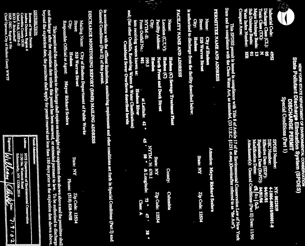
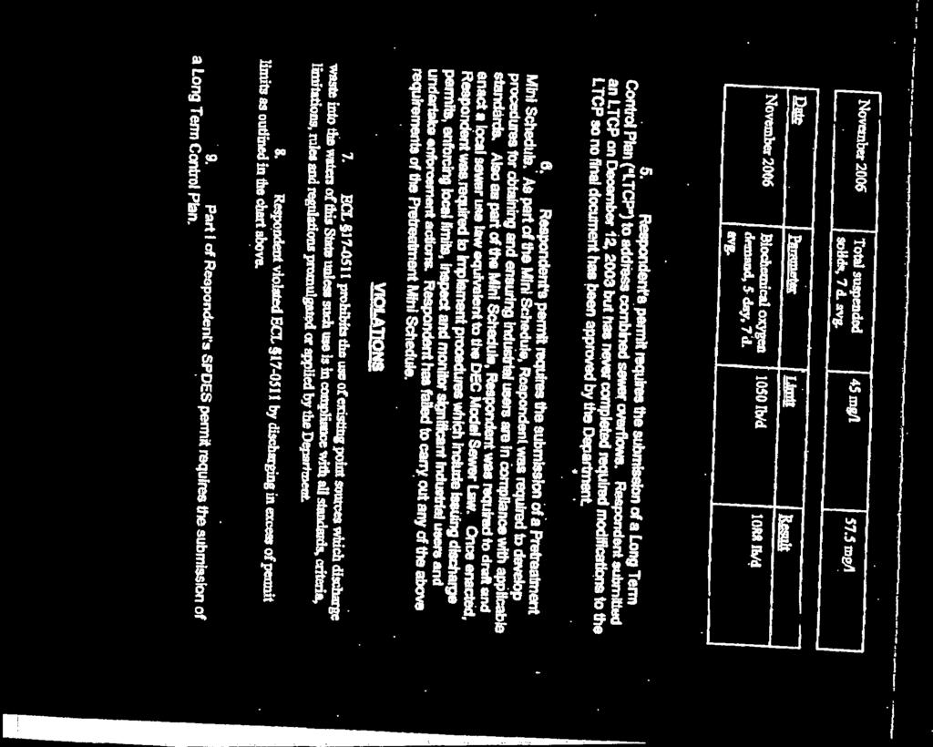
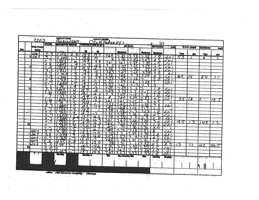
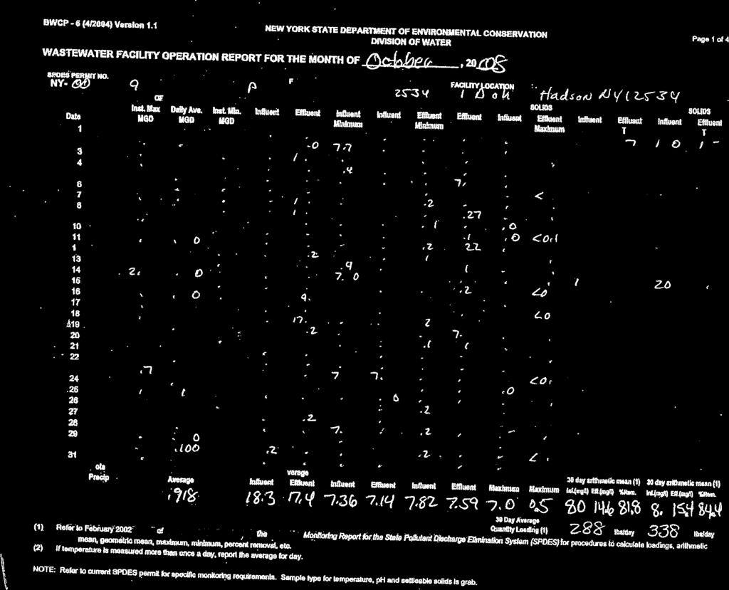
3 City of Hudson Wastewater System Improvement Project Facility Plan Table of Contents Section Page 1.0 INTRODUCTION Description of Existing Facilities Purpose and Need for the Improvement Project Regulatory Standards DESIGN LOADINGS Hydraulic Loading Planning Considerations Organic Loading CAPITAL IMPROVEMENT PLAN SOUTH FRONT STREET PUMP STATION South Street Pump Station Influent Collection System South Front Street Pump Station and Forcemain Pump Station Forcemain WASTEWATER TREATMENT PLANT Design Approach Site Considerations Capacity Unit Process Evaluation and Description of Improvements WWTP Influent Piping Influent Screening, Grit Removal, Septage Handling and Odor Control Primary Settling and CSO Disinfection Process Secondary Treatment Pump Station Activated Sludge Aeration System Secondary Clarification Sanitary Disinfection Sludge Handling Facilities Construction Operations Operation and Maintenance Environmental Review Summary...13 Figures Figure 1 Conceptual Upgrade Plan Site Layout Figure 2 Process Schematic Exhibits Exhibit A SPDES Permit Exhibit B Order on Consent and Modified Order on Consent Exhibit C US Census Data Exhibit D Monthly Operating Reports Exhibit E Septage Receiving Delaware Engineering, P.C. Page i
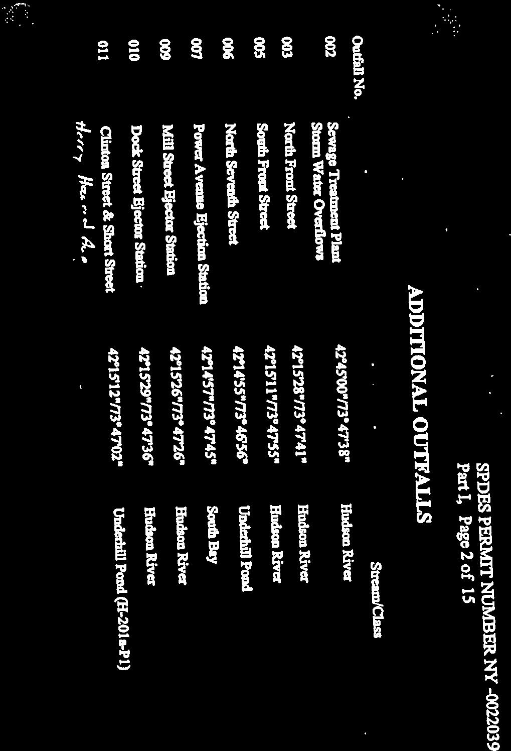
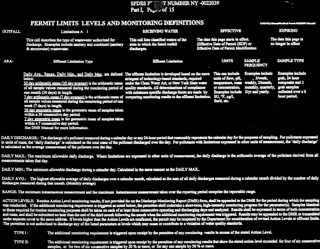
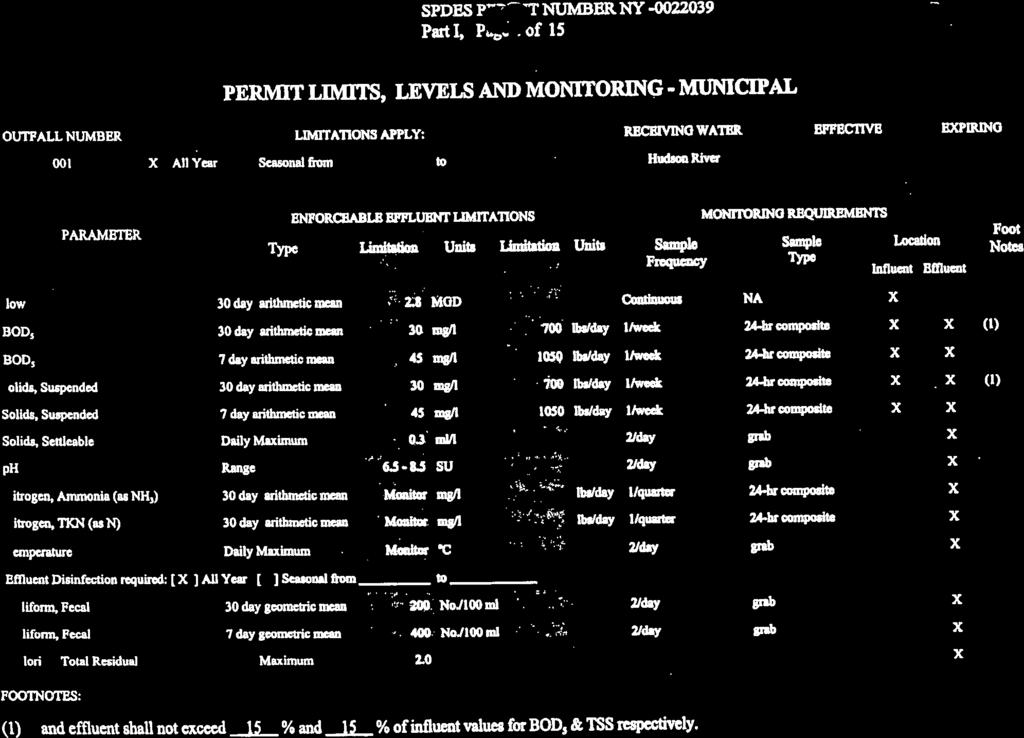
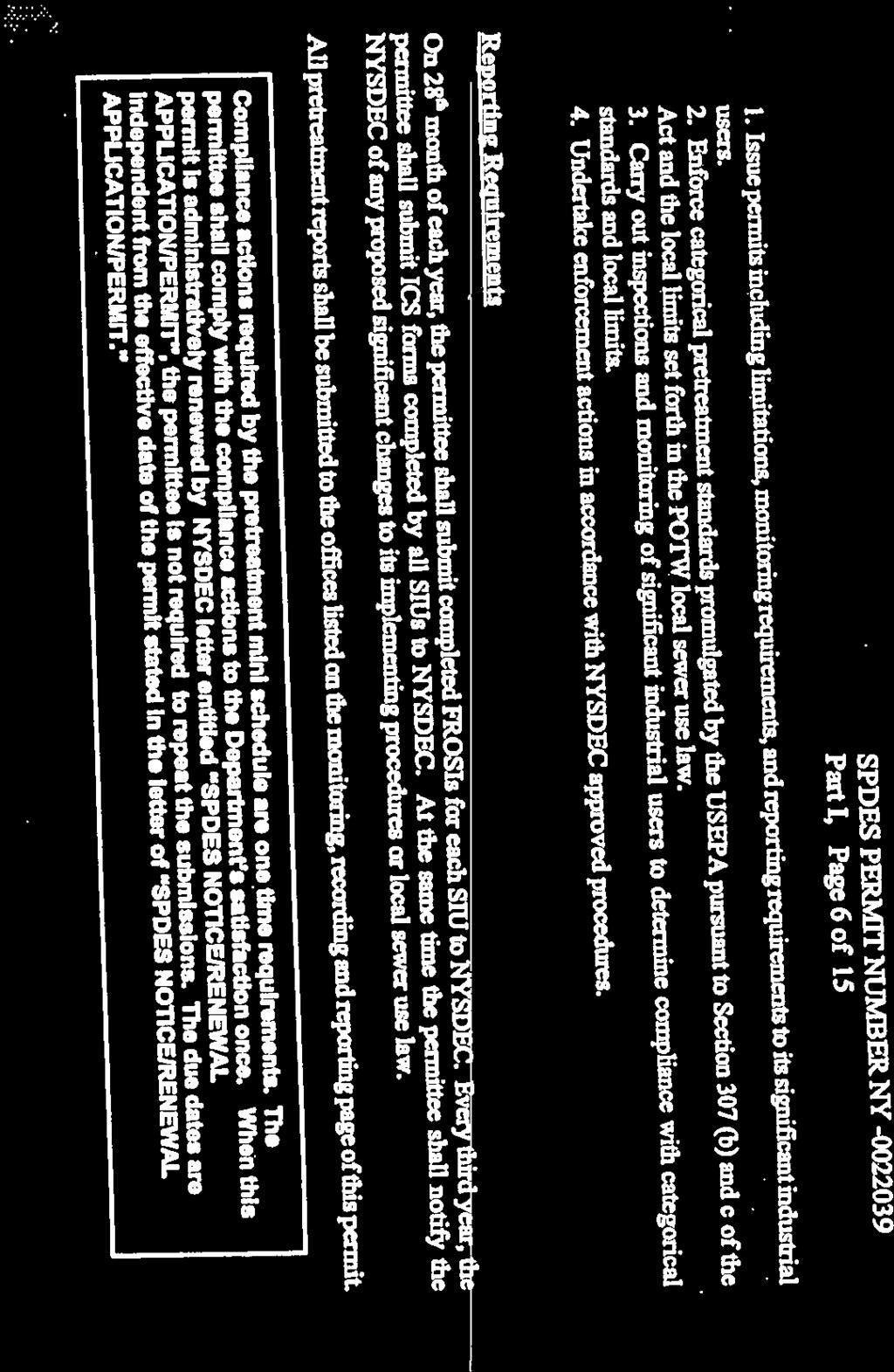
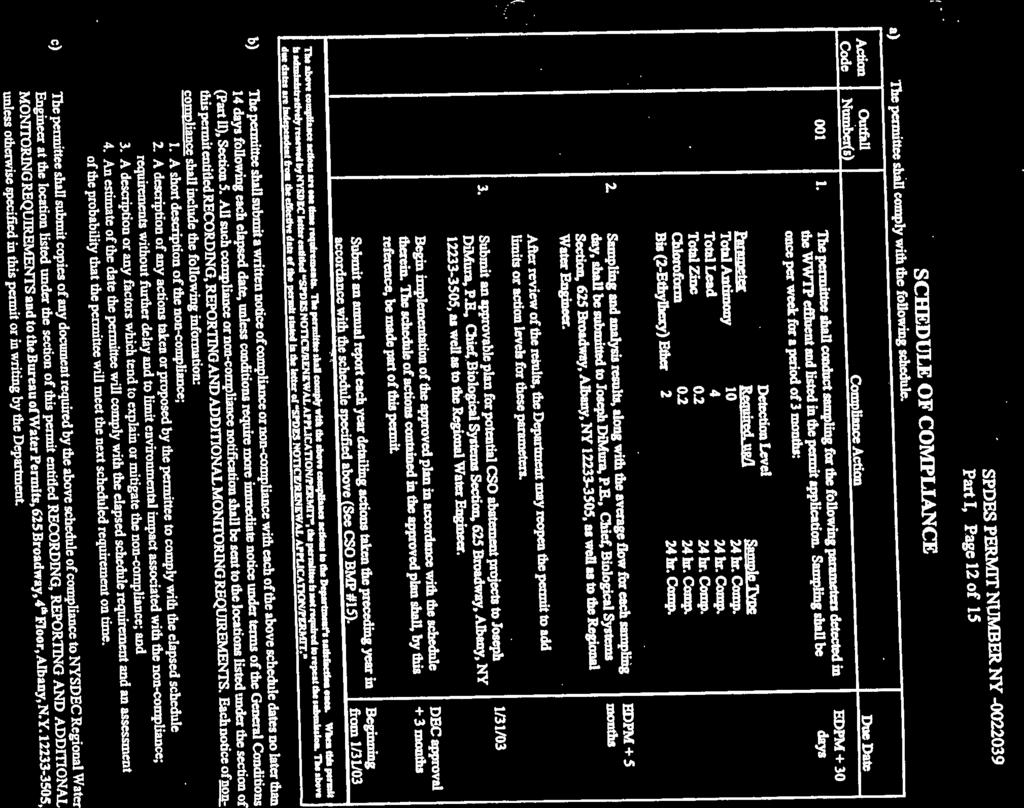
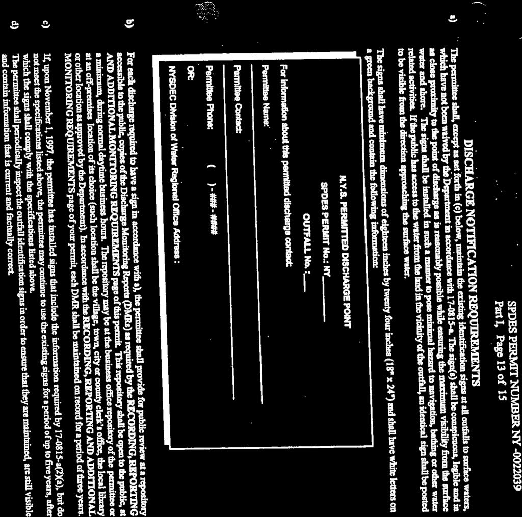
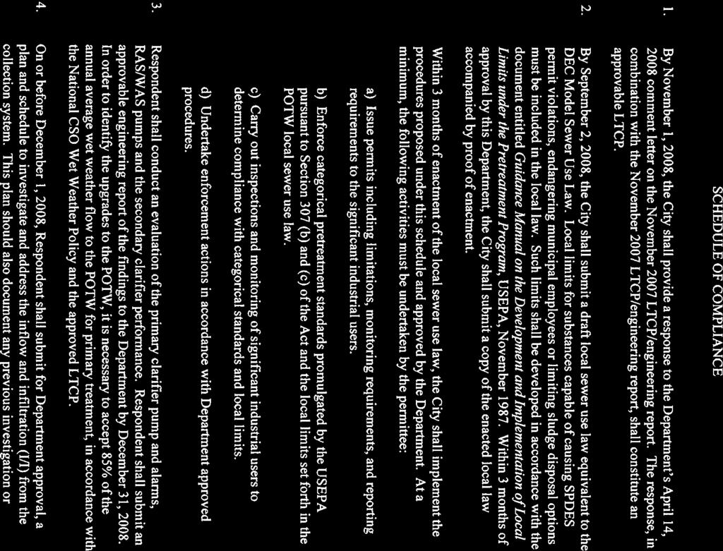
4 City of Hudson Wastewater System Improvement Facility Plan 1.0 INTRODUCTION 1.1 Description of Existing Facilities The City of Hudson Wastewater Treatment Plant is located near the intersection of North Front Street and Dock Street in the City of Hudson, Columbia County, New York. The WWTP is currently permitted to discharge a maximum monthly daily flow of 2.8 million gallons per day (MGD) to the Hudson River via State Pollution Discharge Elimination System (SPDES) Permit #NY (Exhibit A). The wastewater treatment plant was constructed in two phases with the primary system built in the mid-1960 s and secondary treatment components constructed in the late 1970 s. The piping that collects wastewater in the City was constructed over many years, with the majority constructed between the 1830 s and 1930 s. Approximately 70% of the City s piping system for conveying wastewater also collects stormwater in a combined sewer (CSS) and during wet weather events, more water enters the piping system than can be conveyed and treated at the wastewater treatment plant causing overflows. There are eight active combined sewer overflows (CSOs) in the system. The two largest overflows discharge to the North Bay near the WWTP (CSO #002) and to the South Bay (CSO #005), respectively. The City of Hudson collection system contains four pump stations. The largest of these stations is the South Street Pump Station with a published design capacity of 1,950 gallons per minute (GPM). The City also owns and operates three smaller pump stations at Power Avenue, Mill Street and Dock Street. 1.2 Purpose and Need for the Improvement Project The current SPDES permit includes the implementation of Best Management Practices for Combined Sewer Overflows as well as instructions and requirements to prepare a Long Term Control Plan (LTCP) for the facility. In addition, the City s wastewater system functions under Order on Consent number R dated May 2007 and a Modified Order on Consent dated September 2008 (Exhibit B). The Order incorporates requirements for preparation and implementation of a pretreatment program, sewer use law and an LTCP among other items related to developing a design concept for improvements. A Draft Long Term Control Plan entitled Combined Sewer Overflows Long-Term Control Plan, City of Hudson, New York, December 2003 was prepared by Stearns & Wheler and an engineering report was prepared in 2009 and revised in January 2009 by Clough Harbour entitled Engineering Report for Wastewater Treatment Plant and South Front Street Pump Station, City of Hudson, New York, Revised January When considered together, the Draft LTCP and Engineering Report recommend CSO control strategies following the presumptive approach in accordance with the United States Delaware Engineering, P.C. Page 1
5 City of Hudson Wastewater System Improvement Facility Plan Environmental Protection Agency s (EPA) Development and Evaluation of Alternatives for CSO Control published The presumptive approach requires The elimination of the capture for treatment of no less than 85% by volume of the combined sewage collected in the CSS during precipitation events on a system-wide annual average. The Draft LTCP of 2003 utilized collection system modeling with software developed by XP- SWMM, which models storm and sewer systems with modeling practices following the USEPA SWMM model. The 2003 Draft LTCP evaluated the control options and determined that the best control option for the City is to follow the presumptive approach. In order to achieve compliance with the EPA requirements for the presumptive approach, the Draft LTCP recommends upgrade of the South Street Pump Station to 3,500 GPM to convey at least 85% of the volume of the average annual wet weather event flows to the WWTP and improvements to the WWTP to accommodate treatment of 16.9 MGD through the primary treatment process. The 2009 Engineering Report further recommends that primary clarifier overflow controls be configured to direct 6.0 MGD to the secondary treatment process while any volumes over 6.0 MGD up to 16.9 MGD are directed to a disinfection process and then discharged to the Hudson River. This Facility Plan utilizes the fundamental requirements stated in the Draft LTCP and January 2009 Engineering Report in the development of a capital improvements plan to result in the City s achievement of the presumptive approach to CSO control. The requirements that are the basis for this design are: 1. Convey a minimum of 85% of the wet weather flow to the WWTP for primary treatment and disinfection prior to discharge; 2. Primary treatment and disinfection of all flows up to 16.9 MGD at the WWTP; and, 3. Secondary treatment, disinfection and solids handling of 6.0 MGD at the WWTP. 1.3 Regulatory Standards This Facility Plan discusses the background and analysis from the 2003 Draft LTCP and January 2009 Engineering Report as a means to define the volume for 85% capture, a characterization of the hydraulic and organic loading to the WWTP on an average day and under wet weather conditions, a discussion of the improvements required at the South Street Pump Station and the conveyance from that pump station to the WWTP and improvements at the WWTP. This Facility Plan is prepared in conformation with Recommended Standards for Wastewater Facilities - Great Lakes Upper Mississippi River Board of State Public Health & Environmental Managers, dated 2004 and commonly referred to as the Ten States Standards and applicable NYSDEC Design Standards. Delaware Engineering, P.C. Page 2
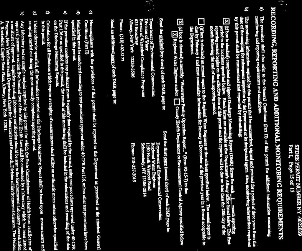
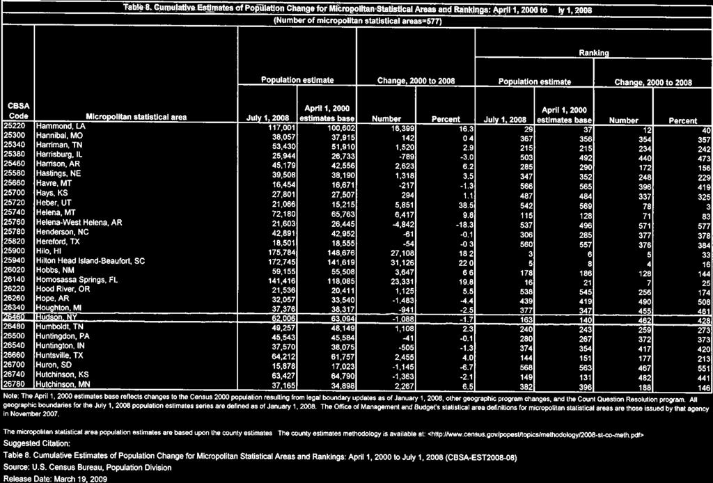
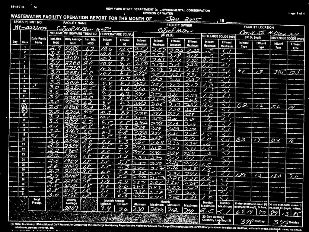
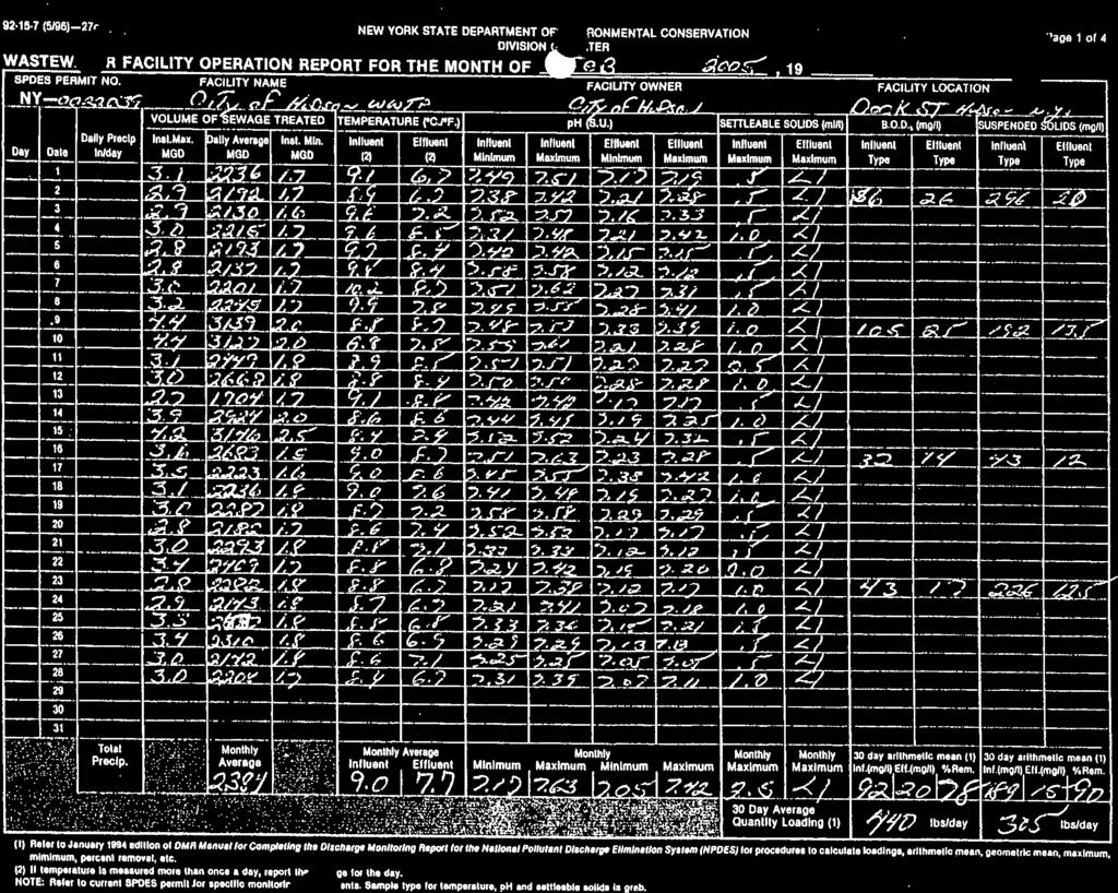
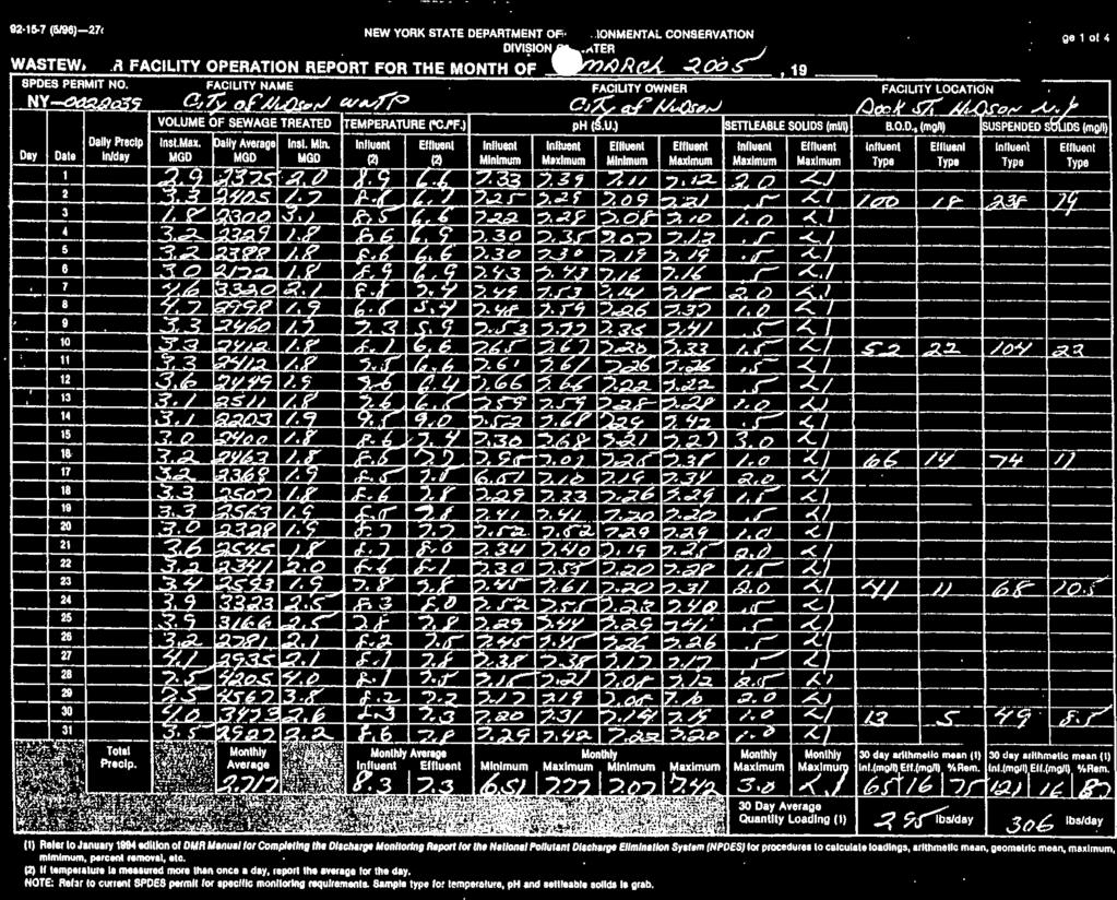
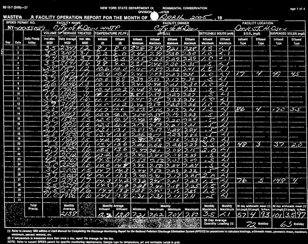
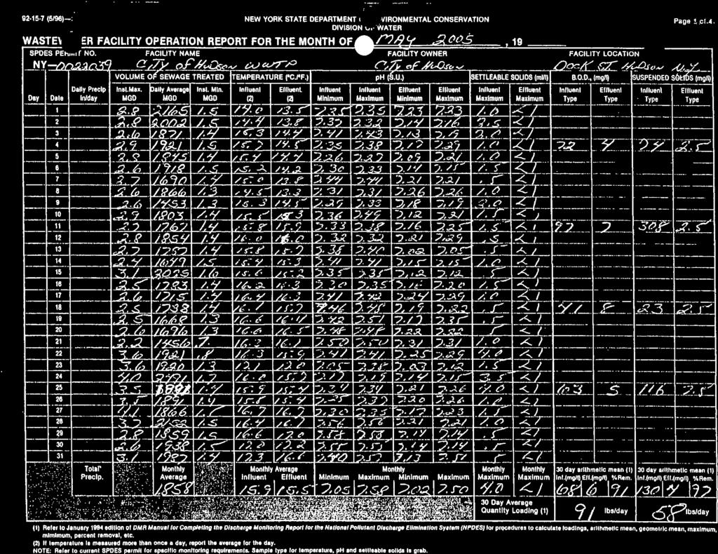
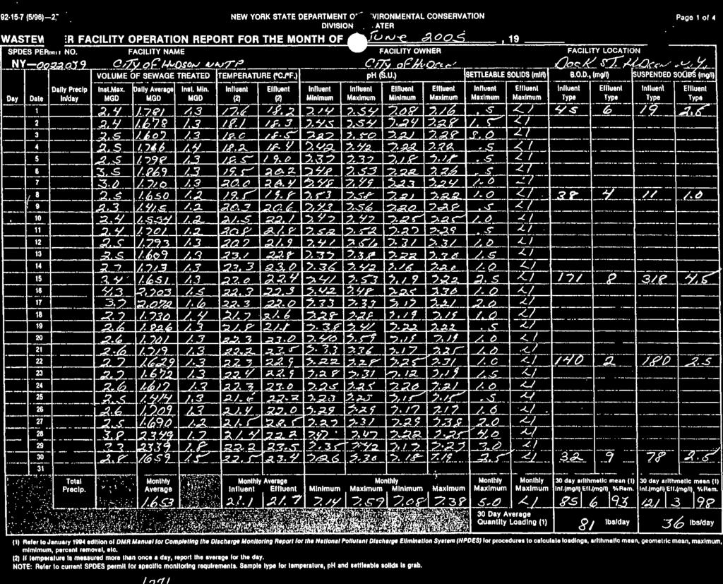
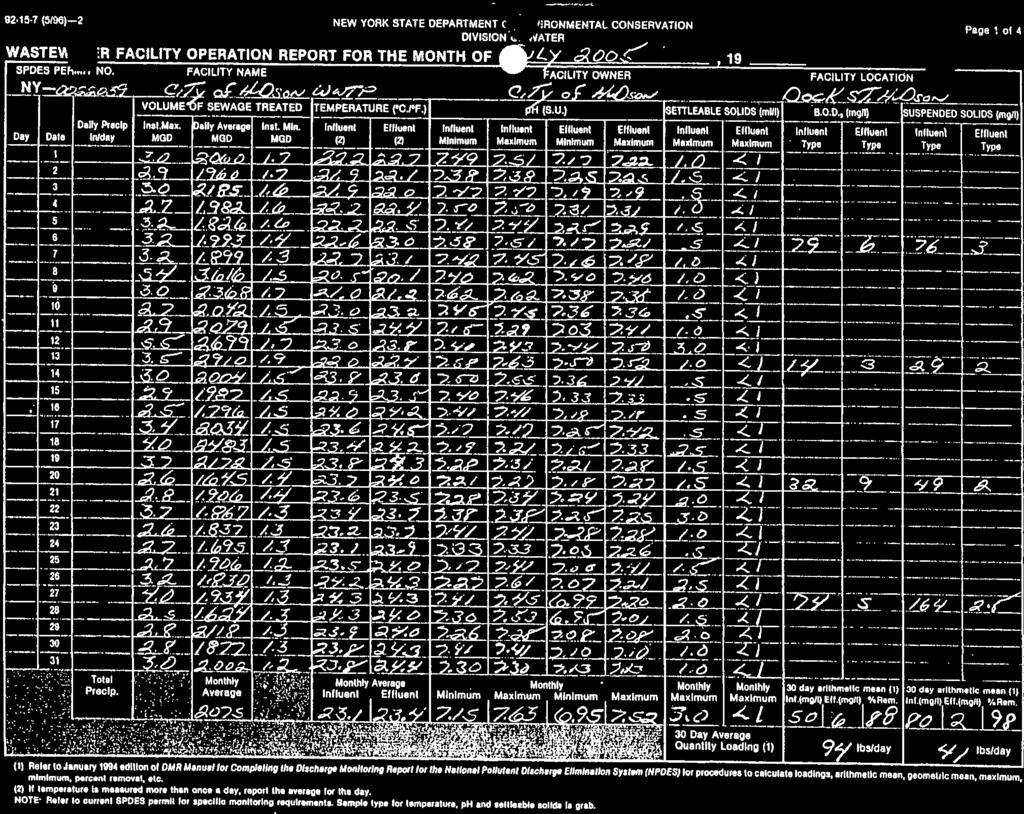
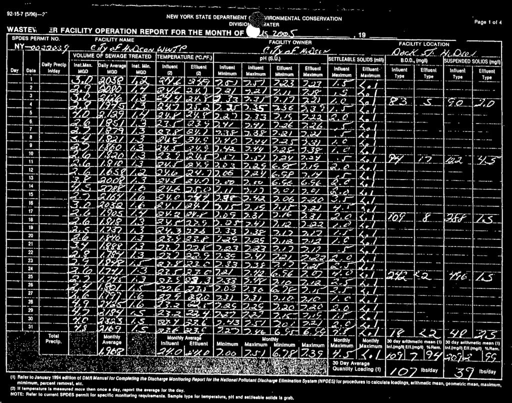
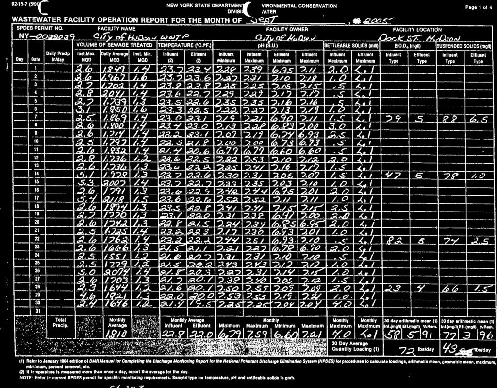
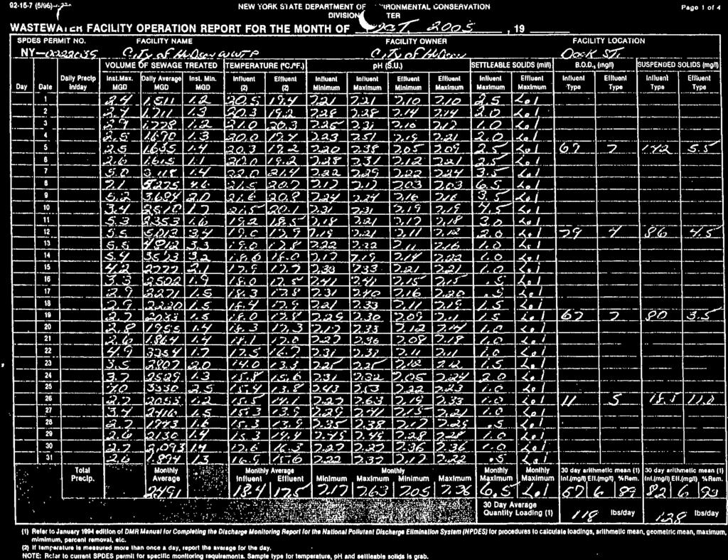
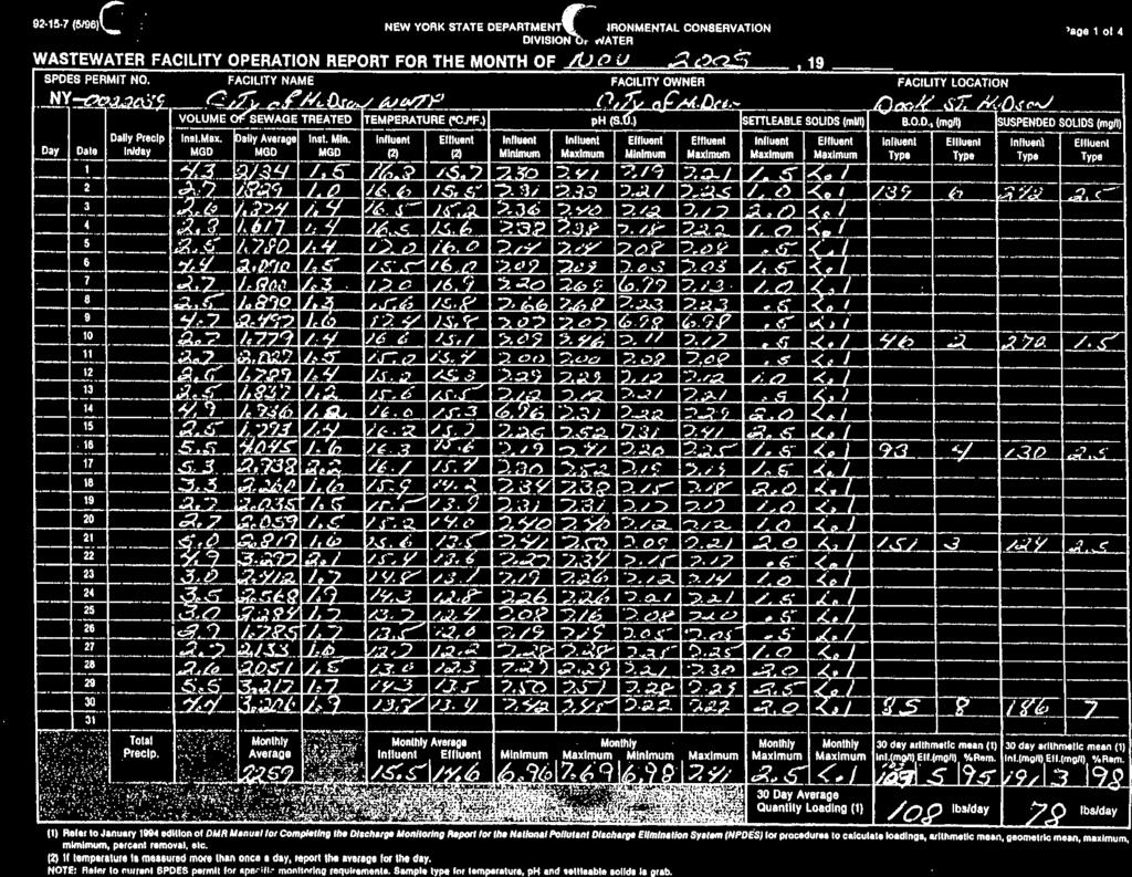
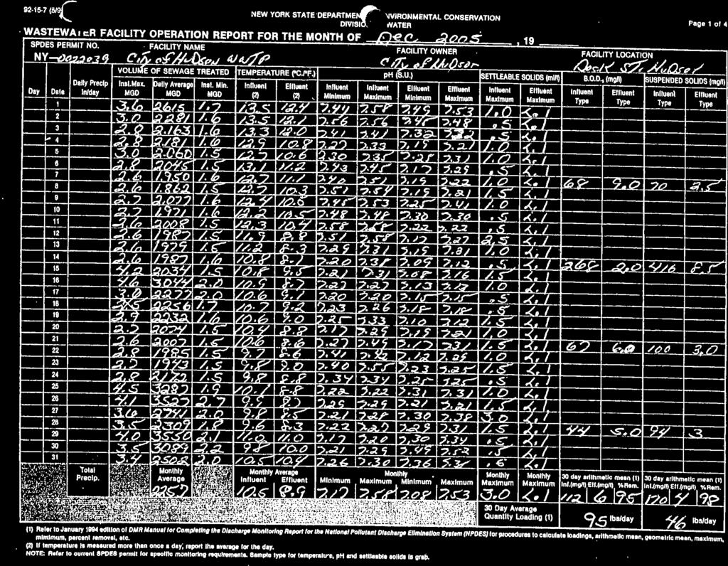
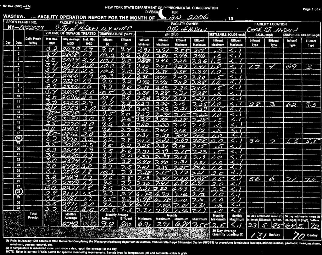
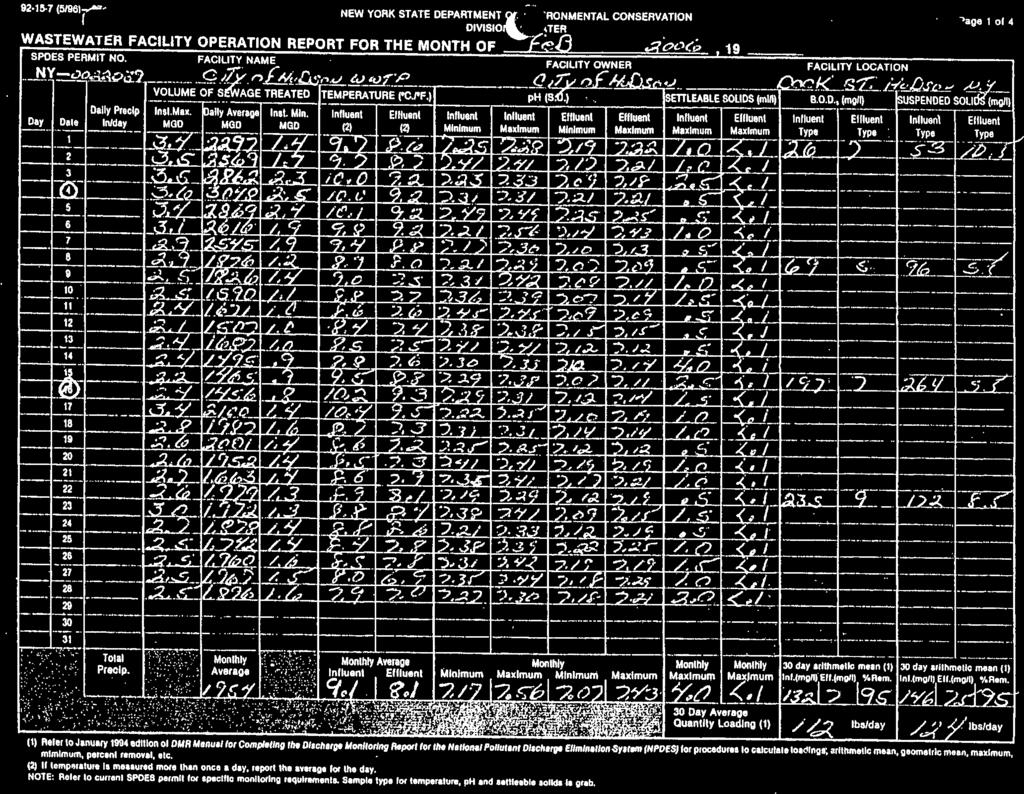
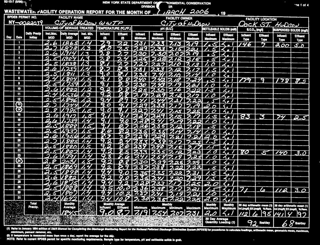
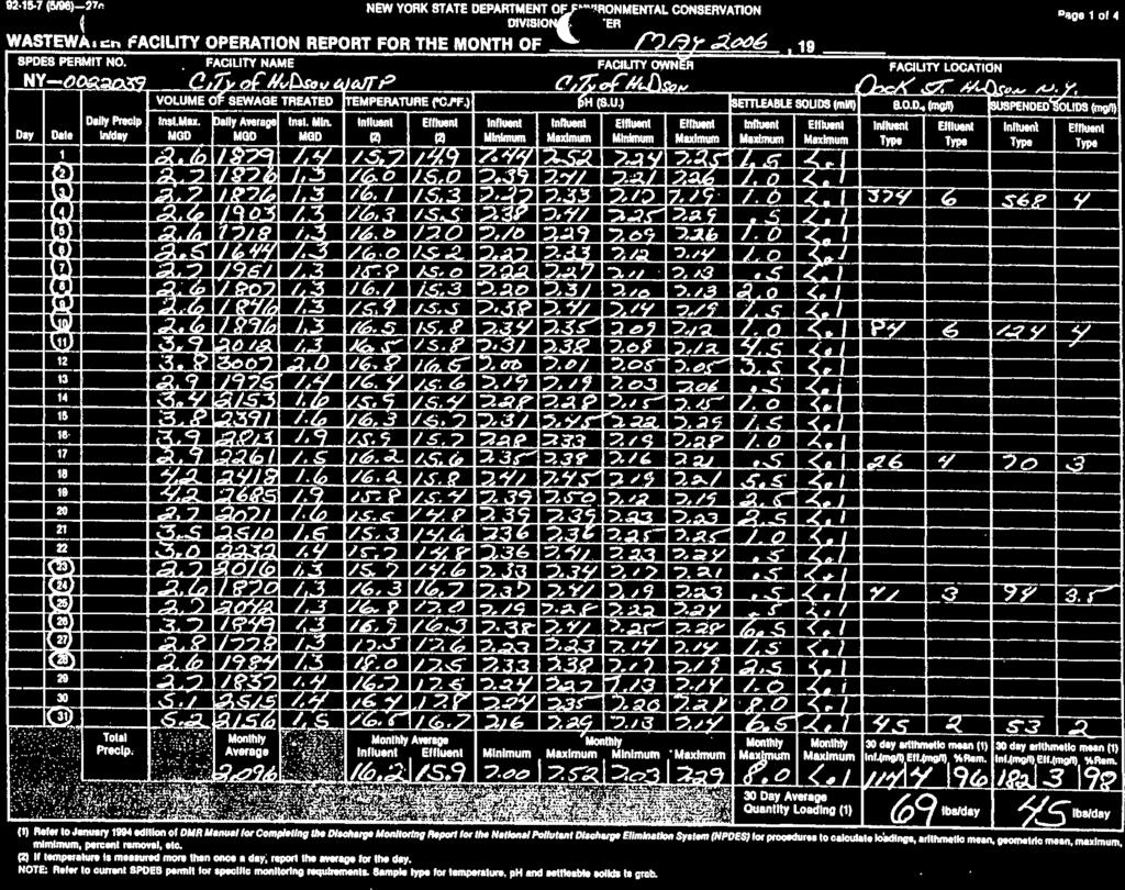
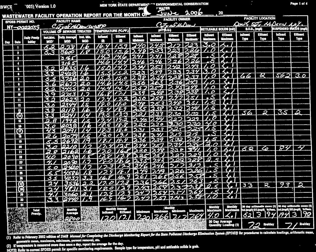
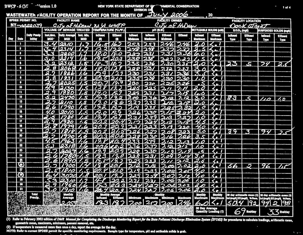
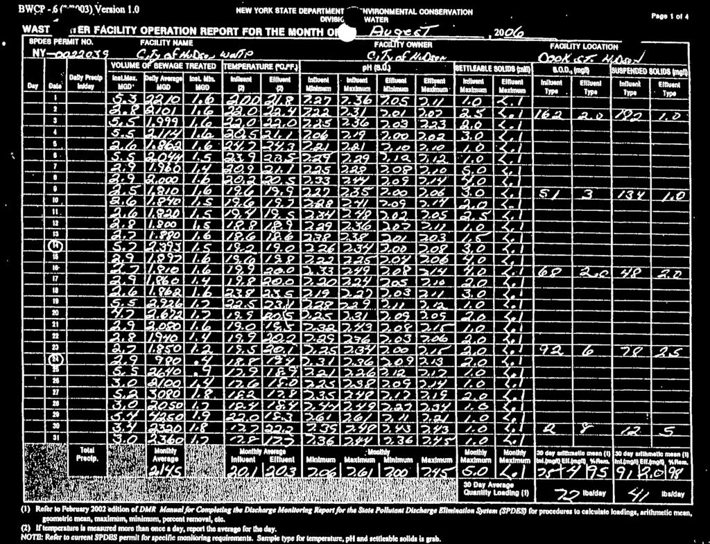
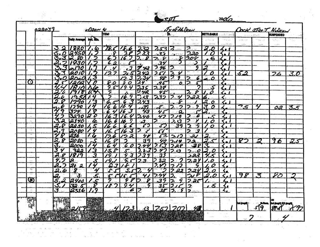
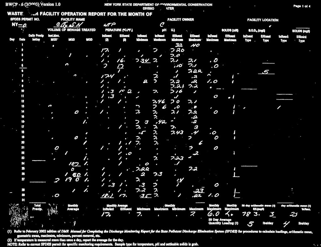
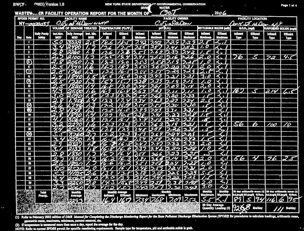
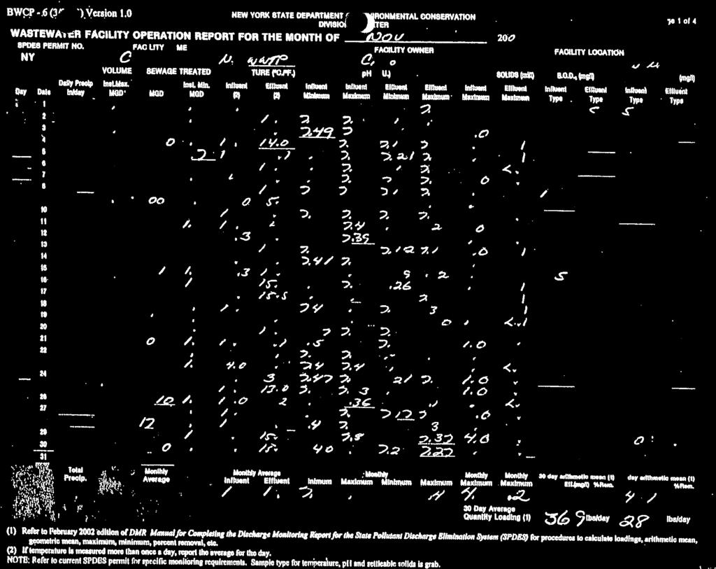
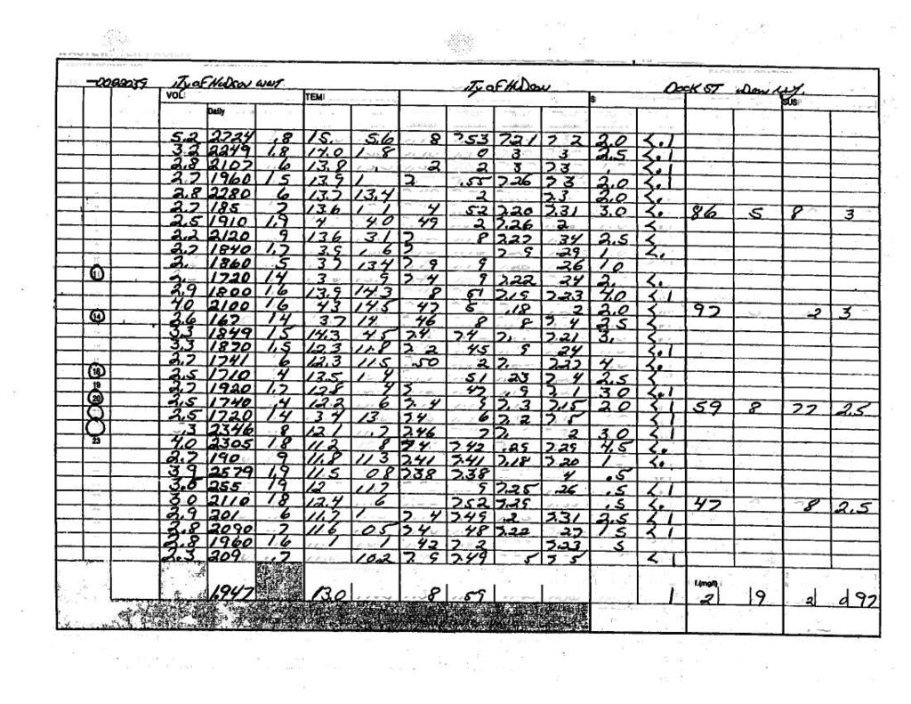
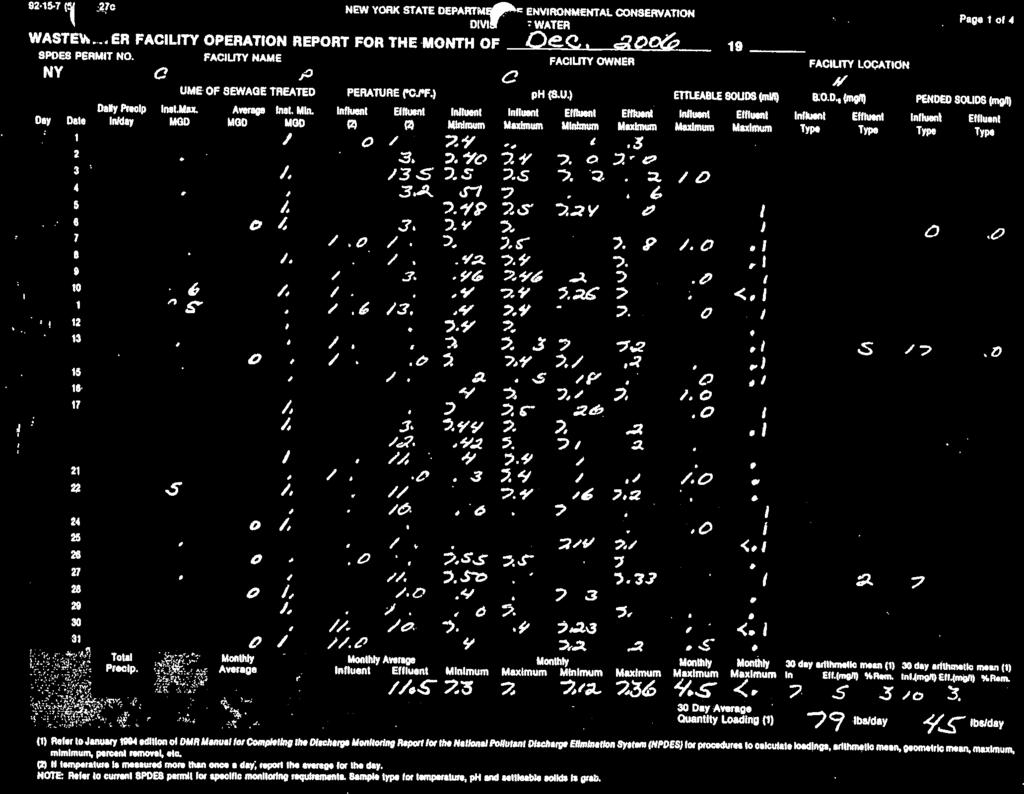
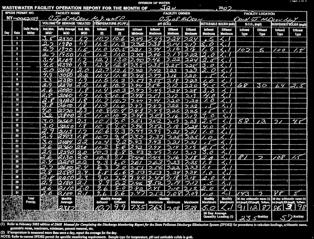
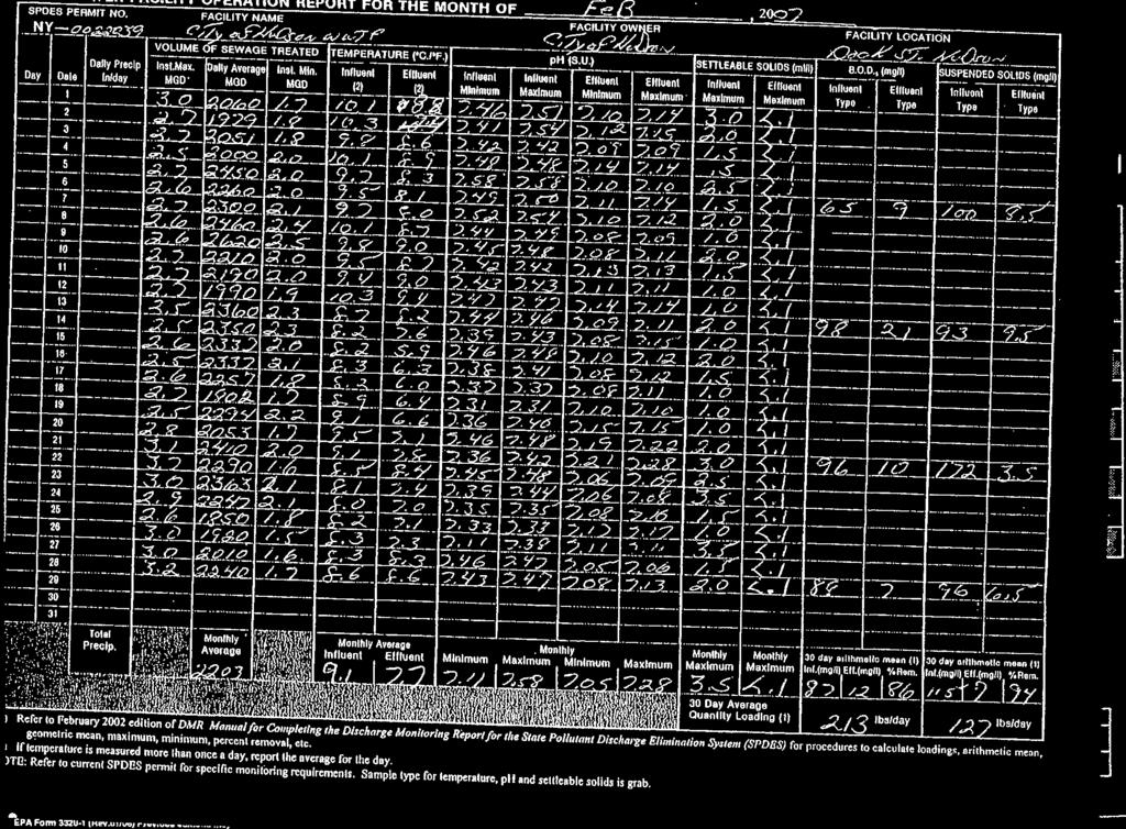
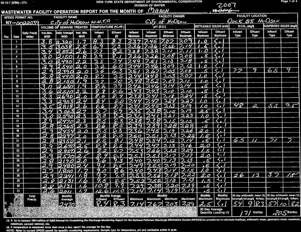
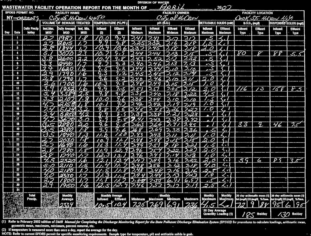
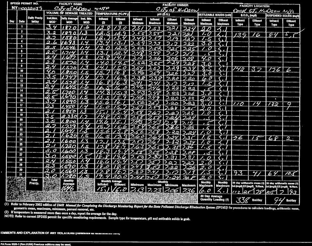
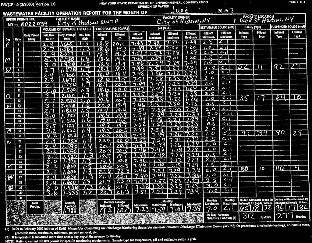
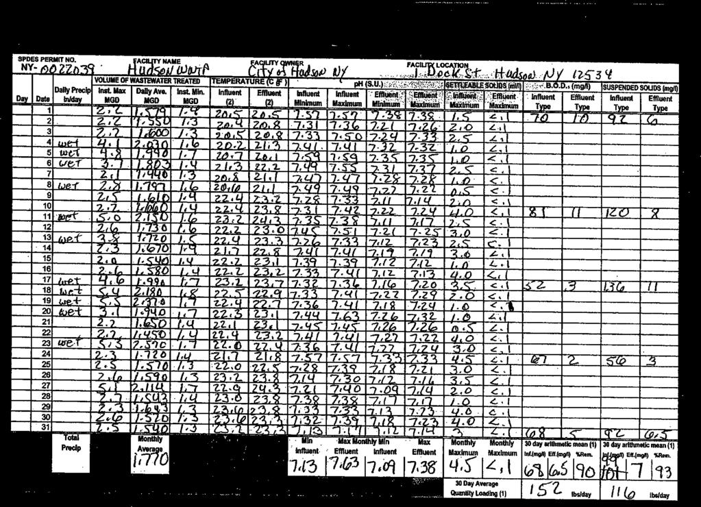
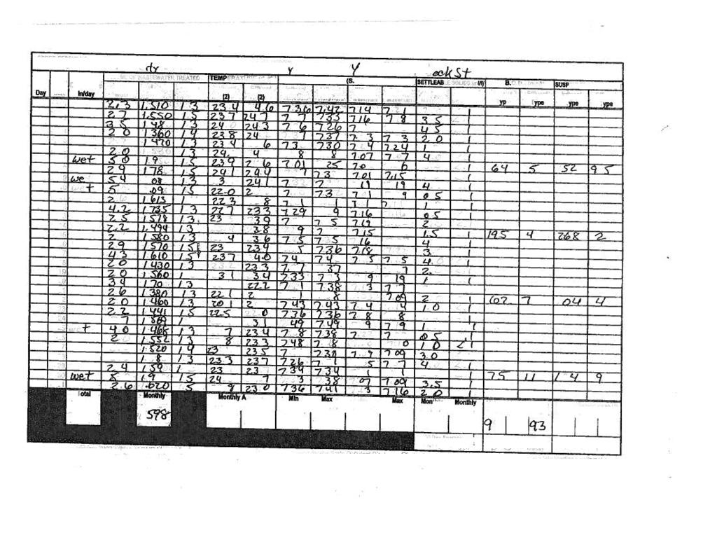
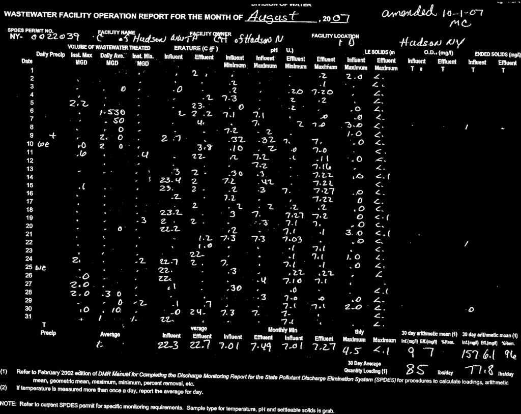
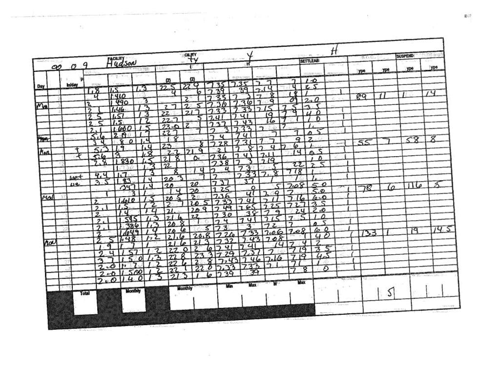
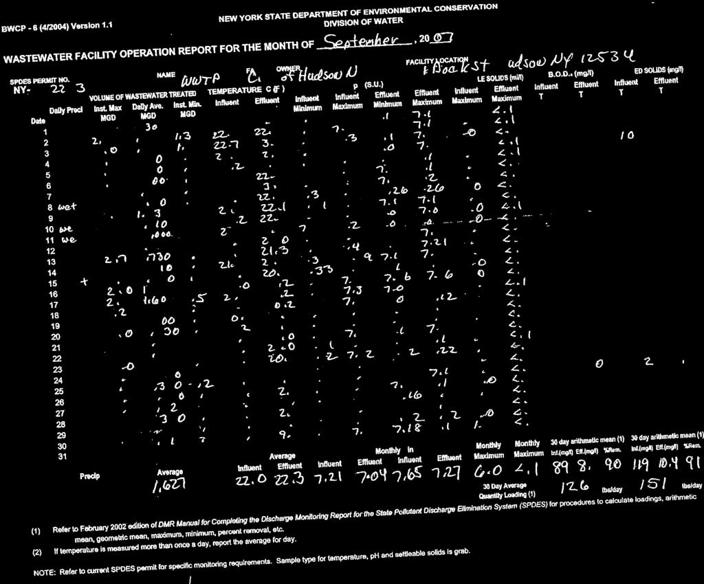
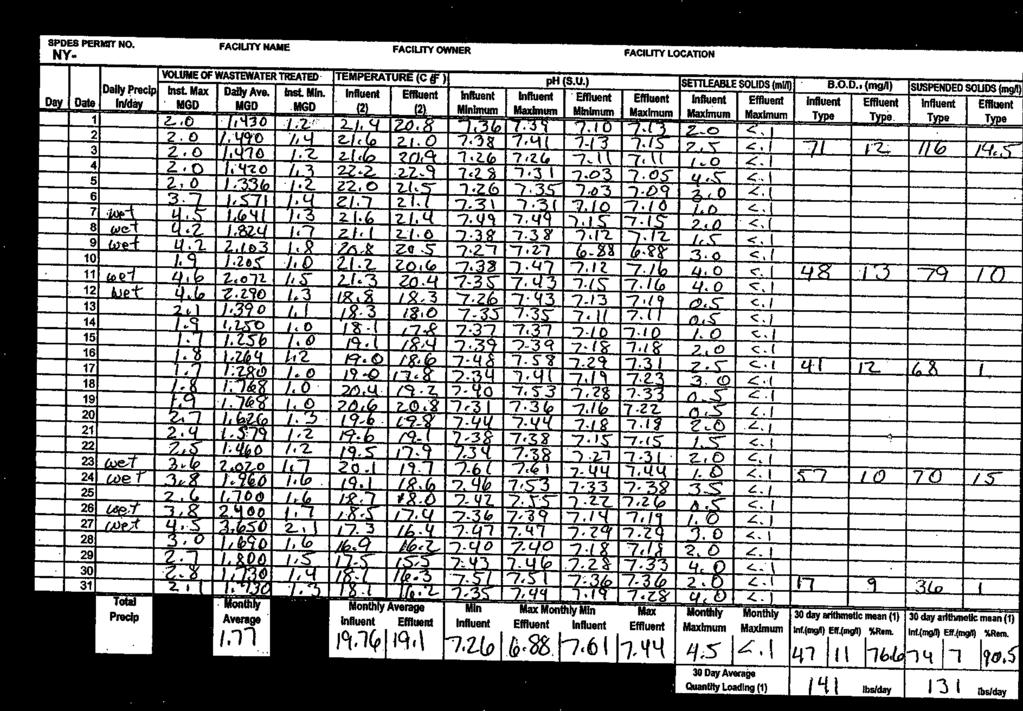
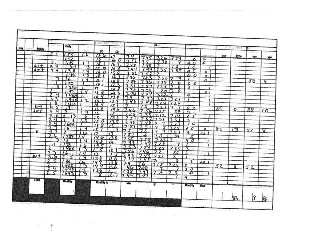
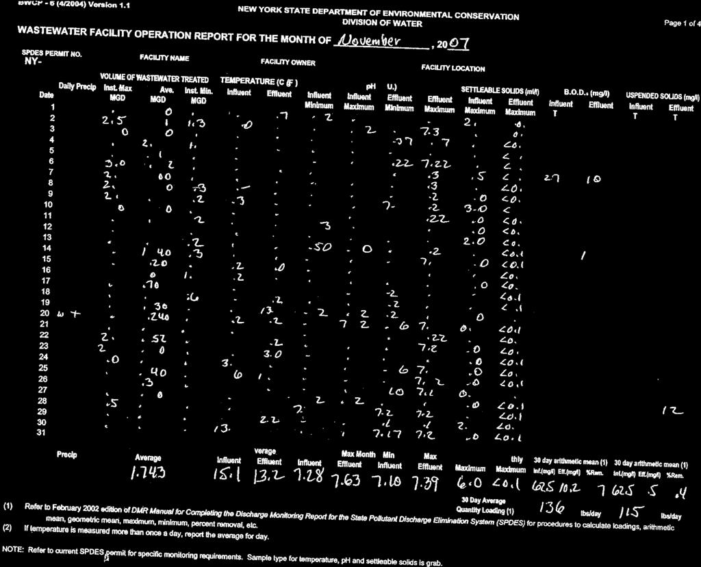
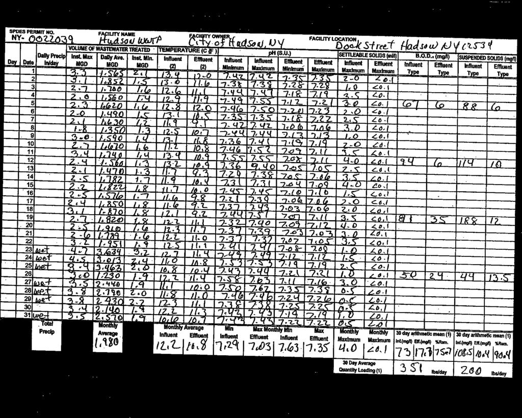
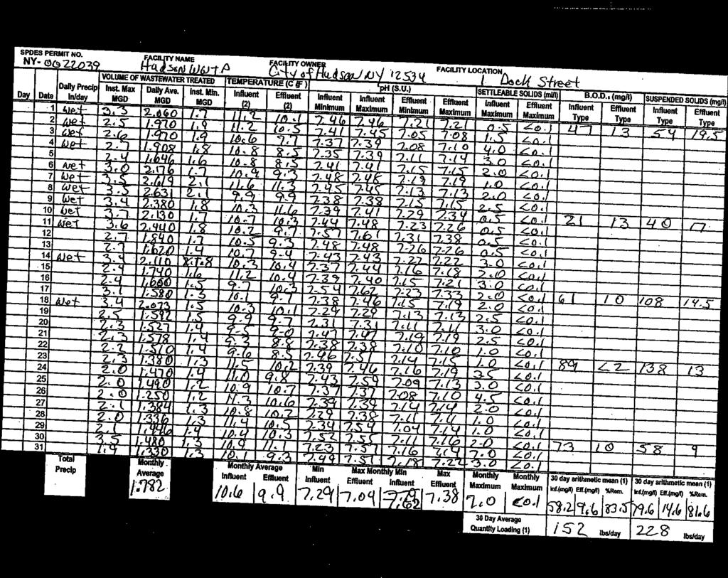
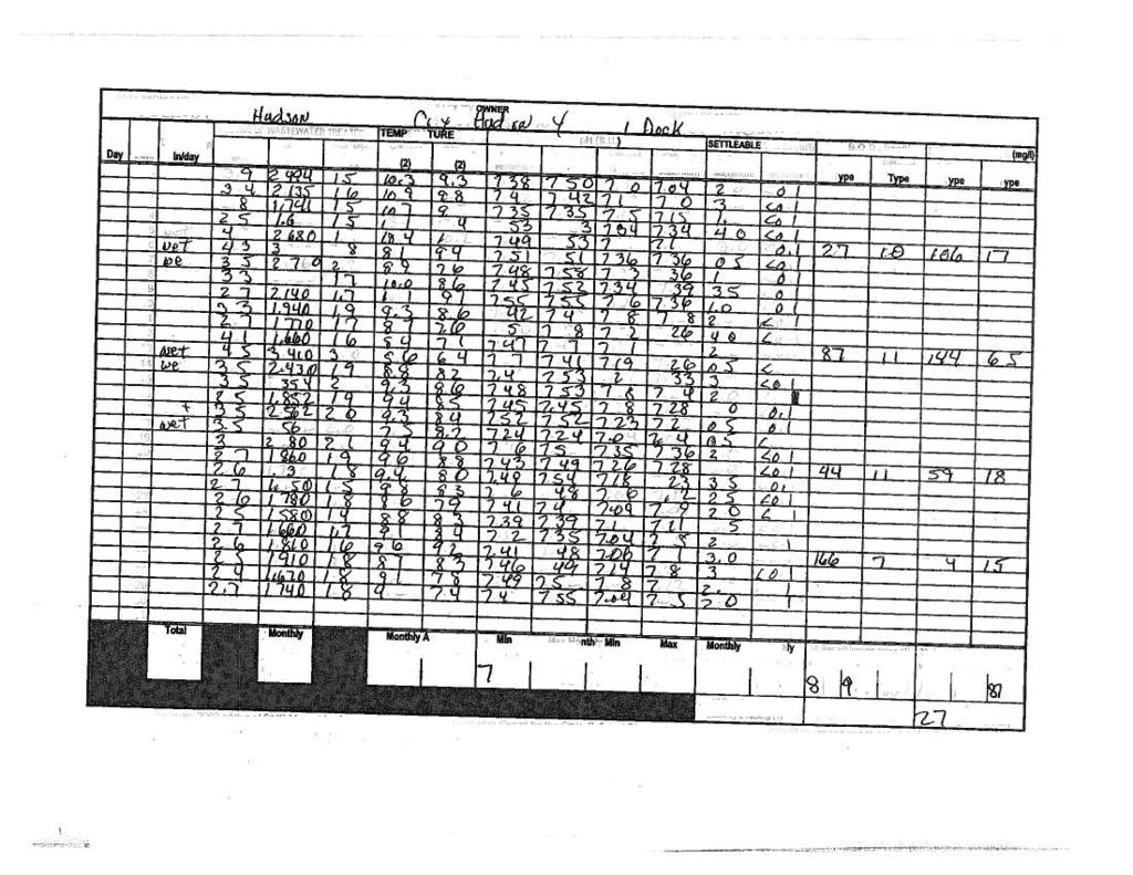
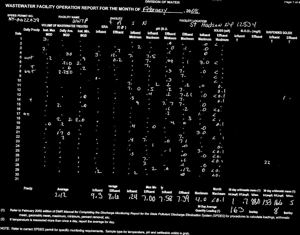
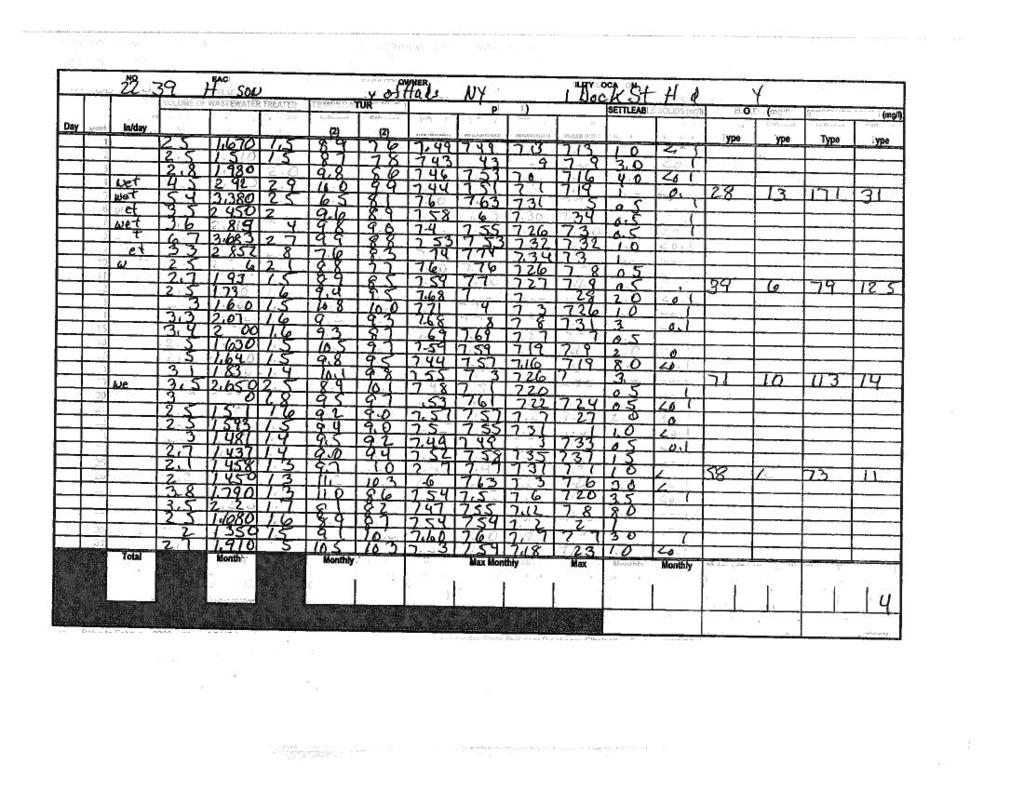
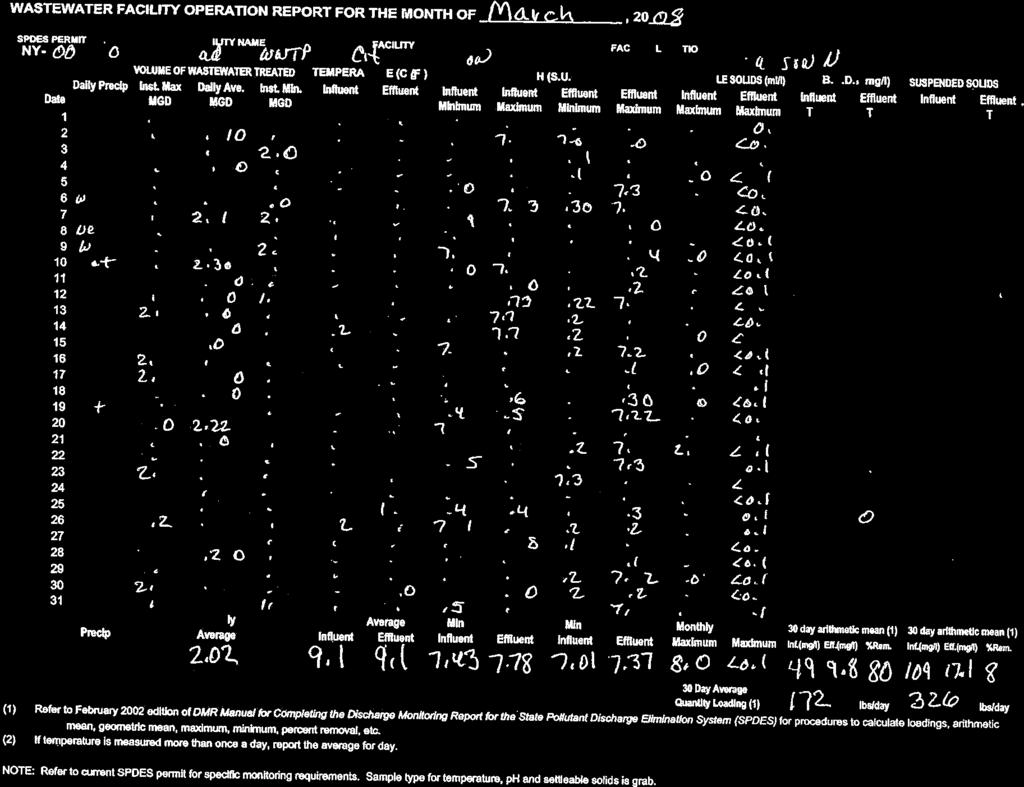
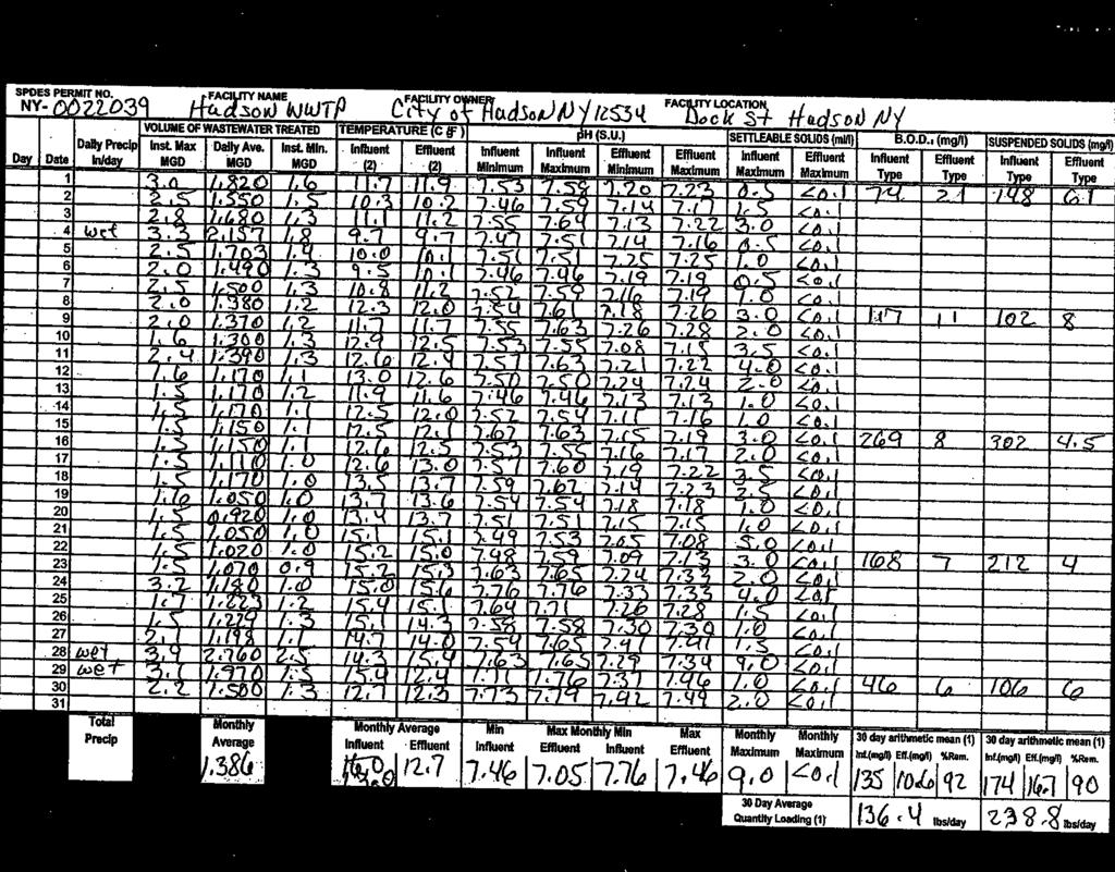
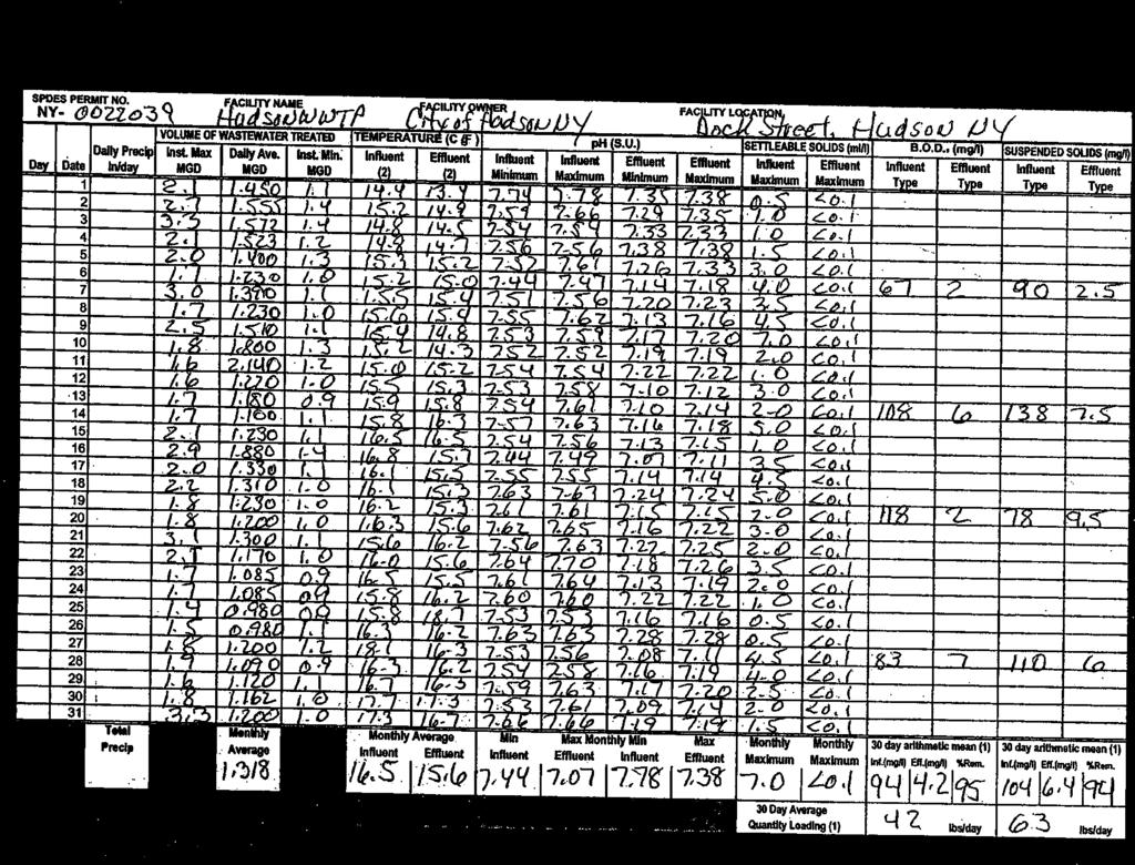
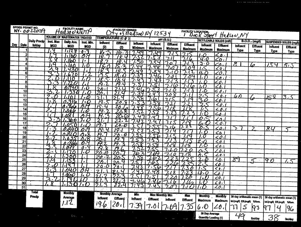
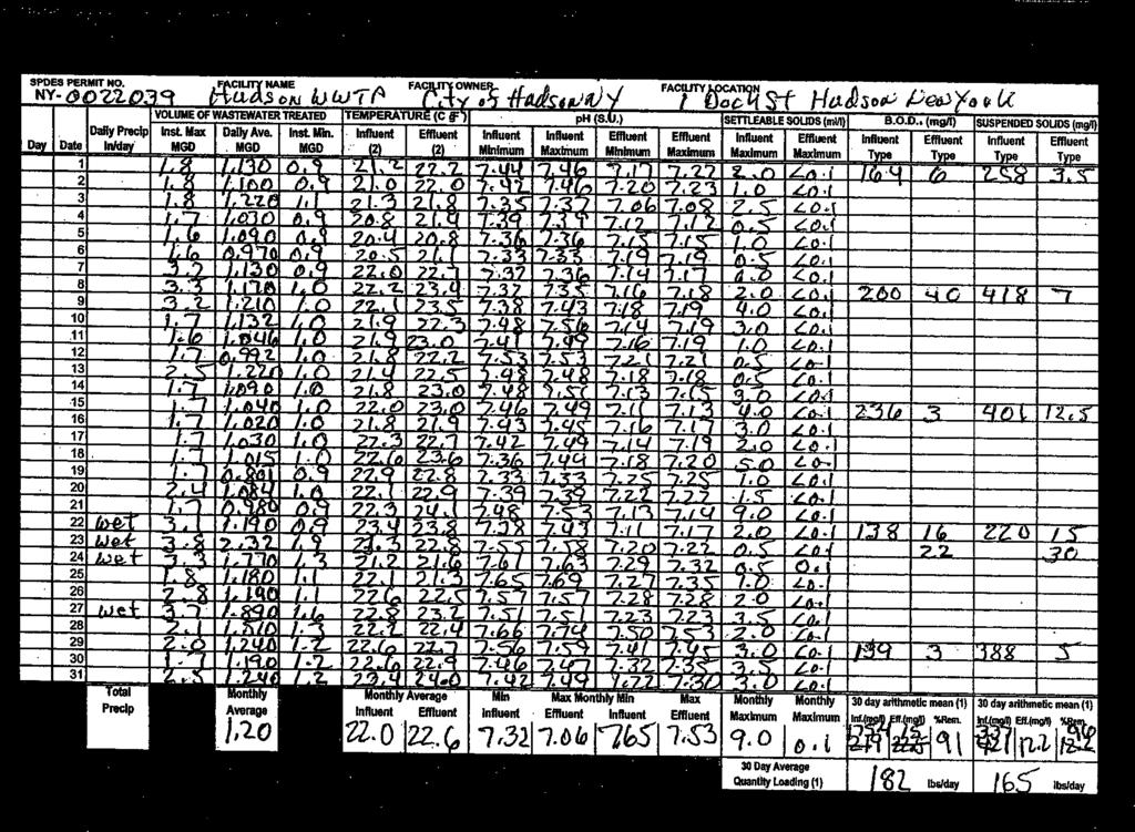
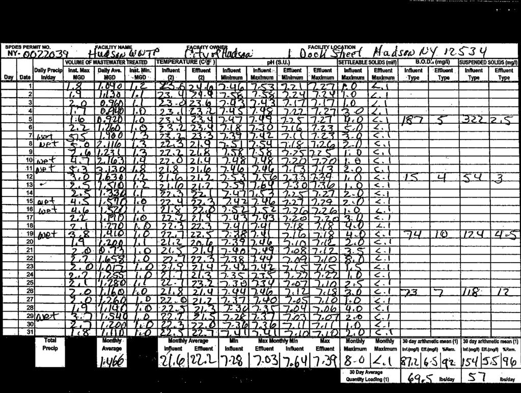
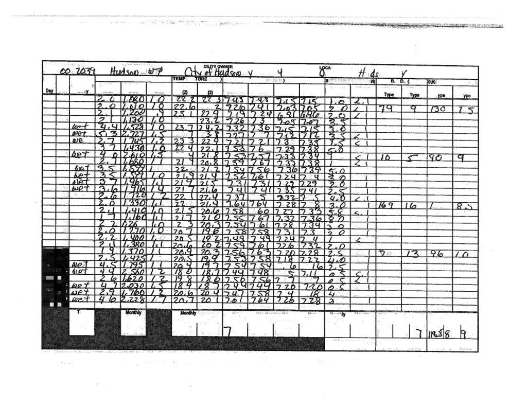
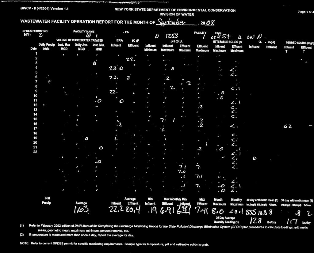
6 City of Hudson Wastewater System Improvement Facility Plan 2.0 DESIGN LOADINGS 2.1 Hydraulic Loading The Draft LTCP Combined Sewer Overflows Long-Term Control Plan, City of Hudson, New York, December 2003 prepared by Stearns & Wheler and the Engineering Report for Wastewater Treatment Plant and South Front Street Pump Station, City of Hudson, New York, Revised January 2009 prepared by Clough Harbour characterize the hydraulic loadings to the WWTP and the South Front Street Pump Station as follows: WWTP Design Flows: 1. Upgraded influent piping with minimum capacity of 16.9 MGD. 2. Primary treatment of 16.9 MGD. 3. Diversion of primary effluent flows over 6.0 MGD to disinfection (10.9 MGD) 4. Secondary treatment and disinfection of 6.0 MGD South Front Street Pump Station: 1. Upgraded influent piping with a minimum capacity of 5.0 MGD (3,500 GPM) 2. Upgraded pump station sized for 5.0 MGD (3,500 GPM) 3. Upgraded forcemain sized for 5.0 MGD (3,500 GPM) 2.2 Planning Considerations Review of Census data (Exhibit C) and local industrial information incorporated in the City s application for Hardship financing indicates that the City of Hudson has experienced an overall decline in population and industrial users over the past several decades up to the present. This trend towards a decline in population coupled with mandated efforts to reduce infiltration and inflow (I&I) and the separation of storm and sanitary sewers indicates that wastewater volumes should decrease over time. While the City seeks to improve its tax base, economic development activities are expected to result in moderate increases in wastewater flows that would be no greater than historic dry weather flows and accommodated by expected reductions in non-sanitary flows. In addition, the City recently adopted a Sewer Use Law and implemented a pretreatment program, aimed at regulating the nature and quantity of wastewater flows to the WWTP. Therefore, the hydraulic capacity provided in the SPDES permit is considered adequate for the purposes of the improvements to comply with SPDES and CSO control criteria. 2.3 Organic Loading The City of Hudson WWTP monitors and records the plant influent and effluent BOD5 and TSS on a weekly basis. Reviews of monitoring records from 2005 through 2008 indicate the values incorporated in Table 2.3 and selected Monthly Operating Reports (MORs) are provided in Exhibit D. Delaware Engineering, P.C. Page 3
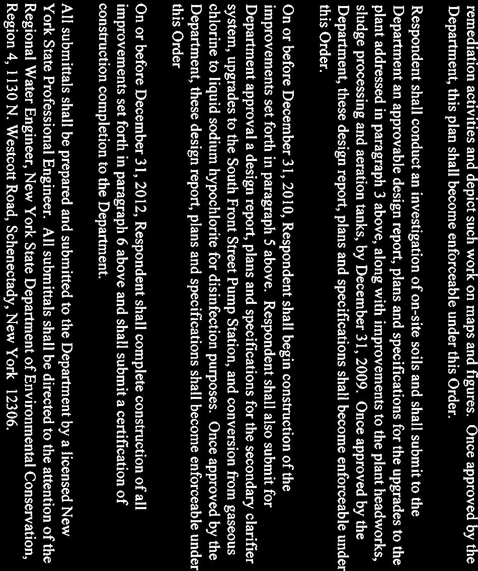
7 City of Hudson Wastewater System Improvement Facility Plan Table 2.3 Organic Loading Parameter BOD5 TSS Average Daily Flow Average Influent Concentration 80 mg/l 119 mg/l 2.02 MGD Published values for domestic wastewater in municipal wastewater systems that do not have combined sewers indicate BOD5 influent concentrations in the range of 210 mg/l and TSS in the range of 250 mg/l. In the case of the City of Hudson, the influent BOD5 and TSS concentrations are significantly lower than typical municipal wastewater most likely due to ground water infiltration and wet weather inflows diluting the wastewater. The Engineering Report Revised January 2009 provides additional details of the characterization of organic/inorganic loading. 3.0 CAPITAL IMPROVEMENT PLAN 3.1 SOUTH FRONT STREET PUMP STATION The Draft LTCP and Engineering Report incorporate upgrades to the South Street Pump Station to 5 MGD (3,500 GPM) capacity to provide for a minimum of 85% wet weather capture and conveyance of flows to the WWTP. In addition, the LTCP and good engineering practice indicate that the pump station should be equipped with emergency backup power. Due to continuous use and wear, the existing pumps in the South Front Street station are not capable of achieving the design values. Recent testing of the pumps indicates actual operational capacity is 850 GPM. While there are three smaller pump stations in the City s collection system, these do not assist directly in capturing 85% of the wet weather flows and conveyance to the WWTP, thus there are no improvements scheduled for these three small pump stations as part of this project South Street Pump Station Influent Collection System Combined sanitary and stormwater are directed to the South Street Pump Station by an 8 and a 16 gravity sewer. The influent enters the wetwell via a stormwater overflow manhole. In the event that the wetwell fills to a level that backs up the overflow manhole, influent overflows a weir in the manhole and discharges to the Hudson River via CSO #005. The capacity of the 16 asbestos concrete gravity sewer in the existing configuration is 2.25 MGD (1,560 GPM), while the capacity of the 8 vitreous tile pipe is 0.50 MGD (350 GPM). The total capacity of the collection system that directs flows into the South Front Street Pump Station under the current configuration is 2.75 MGD (1,910 GPM). Delaware Engineering, P.C. Page 4
8 City of Hudson Wastewater System Improvement Facility Plan To increase the capacity of the collection system servicing the South Front Street Pump Station to 3,500 GPM, the 16 gravity sewer will be upsized from the CSO diversion structure at the intersection of Cross Street and South Front Street to the pump station. The 8 gravity sewer will remain in service South Front Street Pump Station and Forcemain The South Street Pump Station is currently rated for 1,950 GPM. This generally matches the capacity of the collection system in its current configuration. However, the actual operating condition of the pumps indicates a significantly low actual pumping capacity. To bring the capacity of the station to 3,500 GPM (5 MGD), the pumps and the 12 forcemain will be replaced Pump Station Currently, the South Front Street Pump Station has a rated capacity of 2.8 MGD (1,950 GPM). In consideration of the hydraulic loadings provided in the 2003 Draft LTCP, an upgrade of the pump station is proposed to a capacity of 5 MGD (3,500 GPM). The stations existing configuration consists of three (3) pumps each rated for 650 GPM at 64 TDH. To accommodate 5 MGD of flow, these pumps will be replaced with three dry-pit submersible pumps each rated for 1,750 GPM. These pumps will be VFD driven and will accommodate dry weather flows with one pump in operation. The upgrades to the station will include installation of an emergency generator sized to operate two of the 1,750 GPM pumps. Upgrade components that could be impacted by flooding will be installed above the 100 year flood elevation, established in City records as Forcemain The South Street Pump Station currently discharges through approximately 1,500 LF of 12 cast iron forcemain to a 12 gravity sewer located at the intersection of North Front Street and Prison Alley. The capacity of the forcemain without excessive energy loss is calculated to be approximately 2.9 MGD (2,000 GPM). Utilizing this forcemain for 5 MGD would require excessively large pumps and would not be an energy efficient design. In addition, this pipe has been in service since 1963, and the condition of the pipe is unknown. The capacity of the 12 gravity sewer into which the forcemain discharges is approximately 1.5 MGD. To accommodate conveyance of 5 MGD from the pump station, the forcemain will be upsized and extended to discharge to a larger gravity sewer. The forcemain discharge will be extended approximately 170 LF to the north to discharge to the 48 RCP sewer at the intersection of Columbia Street and North Front Street. Delaware Engineering, P.C. Page 5
9 City of Hudson Wastewater System Improvement Facility Plan 3.2 WASTEWATER TREATMENT PLANT Design Approach Utilizing the Draft LTCP and January 2009 Engineering Report hydraulic loadings as well as detailed review of operating data for influent organic loadings and a knowledge of the SPDES discharge parameters and CSO control objectives, an evaluation of each unit process at the WWTP was conducted. This review establishes original design intent and capacity, actual current operating conditions, and improvements required to achieve SPDES compliance and established CSO control objectives. In addition, consideration was applied to the creation of an overall capital improvements plan that allows the existing plant to remain functional while improvements are installed in a cost effective and timely manner. The following unit processes were evaluated: 1. Influent Piping 2. Influent Screening, Grit Removal and Septage Handling 3. Primary Settling 4. Flow Metering 5. Secondary Treatment Pump Station 6. Activated Sludge Aeration System 7. Secondary Clarification 8. Sanitary and CSO Disinfection 9. Sludge Handling Facilities 10. Odor Control 11. Ancillary Facilities (office, lab, workspace, etc.) Site Considerations Site considerations that present opportunities and challenges in developing improvements to the City of Hudson WWTP include the location of the facility with respect to nearby land uses, tidal influences and site geology, existing plant layout, and public safety and odor issues. Immediately adjacent land uses include a small marina and the North Bay to the north, a wetland to the northeast, the City s vehicle maintenance facilities to the southeast, Dock Street to the southwest and Front Street to the west. The neighborhood in which the WWTP is situated is characterized by active light industrial buildings, abandoned structures and the City s now-closed landfill. Residential properties are located outside the immediate neighborhood to the south and southwest of the WWTP. Thus, the treatment plant is consistent with adjacent land uses. While the WWTP is not an inconsistent use relative to adjacent properties, efforts will be made during the design of improvements to improve the appearance of the site and structures. Portions of the collection system and the outfalls from some of the CSOs are influenced by Hudson River tides and groundwater levels are near the surface in some locations. In constructing the existing plant, particularly the secondary treatment process, fill was used Delaware Engineering, P.C. Page 6
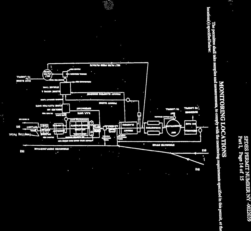
10 City of Hudson Wastewater System Improvement Facility Plan to level and grade the site and allow for construction of facilities at elevations protected from flooding. All new structures will be designed at appropriate elevations relative to the flood plain. Construction phase stormwater controls will be instituted as appropriate. There is adequate area on the site to logically configure the improvements without major modifications or relocation of existing facilities. Figure 1 illustrates the logic and flow of the site plan. Improvements will be made that will address public safety concerns. The facility currently utilizes chlorine gas for disinfection. While chlorine gas is an efficient and effective disinfectant, storage and handling require precautions to ensure safety. The improvements include replacing the chlorine gas system with liquid chlorine disinfection. The liquid chlorine storage will incorporate containment and proper signage for safety reasons. Finally, the existing plant does not incorporate odor control equipment. The improved plant will utilize odor control processes to handle influent and sludge processing odors Capacity The capacity of each unit process is evaluated based on Average Annual Daily Flow (ADF), Average Monthly Maximum Daily Flow (MMDF) and/or Peak Hourly Flow (PHF). The design flow conditions are in accordance with the 2003 Draft LTCP and are represented in Table Table Design Capacity Parameter Average Daily Flow (ADF) Maximum Monthly Daily Flow (MMDF) Peak Hourly Flow Primary Treatment Peak Hourly Flow Secondary Process 2.1 MGD 2.8 MGD 16.9 MGD 6.0 MGD Flow In accordance with current regulatory standards and good engineering practice, each unit process requires a specific hydraulic design standard. The overall plant capacity is then rated as the capacity of the unit process with the most restrictive design capacity. The existing facility currently operates under a SPDES permit that sets the discharge value at 2.8 MGD based on the Average Maximum Monthly Daily Flow (MMDF). Figure 2 provides labels identifying proposed SPDES sampling and flow monitoring points. Delaware Engineering, P.C. Page 7
11 City of Hudson Wastewater System Improvement Facility Plan Unit Process Evaluation and Description of Improvements The existing site and unit configuration is provided on Figure 1, with improvements interposed on the site. Figure 2 provides a more detailed Process Schematic. The following narrative describes the illustrated improvements WWTP Influent Piping The influent piping to the WWTP consists of a 20 sanitary gravity sewer configured as an inverted siphon. The capacity of the influent piping is approximately 10.0 MGD and will be upgraded to accommodate the additional flow from the South Street Pump Station along with wet weather flow from CSO #002 located on North Front Street. Influent piping to the WWTP shall accommodate at least 16.9 MGD and shall maintain elevations sufficient to protect the system from tidally influenced waters in the existing CSO Outfall Influent Screening, Grit Removal, Septage Handling and Odor Control The screening at the WWTP is currently performed by two manually cleaned bar racks. The plant is equipped with a mechanical bar rack; however, this unit has not been operational since The existing screening process will be replaced with two new mechanically cleaned influent screens capable of operating at a capacity of 8.5 MGD each to provide a total capacity of 16.9 MGD. Screens will be equipped with a solids compactor and conveyor to discharge dewatered compacted solids to a dumpster for off-site disposal at a landfill. A bypass channel equipped with one manually cleaned bar rack capable of handing 8.5 MGD will also be provided to allow operational flexibility and the ability to maintain the other two mechanical units without an interruption in service. A septage handling system will be provided to allow the facility to accept septage from local haulers. Exhibit E incorporates a determination from NYSDEC as to the sources and volumes of septage permitted to be received. Screened septage will be discharged to the existing sludge holding tank located in the existing headworks area where it will be aerated prior to being pumped into the wastewater treatment process at a controlled rate. The septage handling facilities and headworks will be equipped with odor control consisting of activated carbon vessels and blowers. Grit is currently removed by a 14 x 14 grit chamber located directly downstream of the influent screens. This system operates by funneling the inorganic solids to the bottom of the tank. The degritted wastewater discharges from the grit chamber via an overflow weir. The grit is pumped from the bottom of grit chamber by a vortex pump to a cyclone grit classifier located in the separator building. The dewatered grit is then transferred to a dumpster for off-site disposal. Delaware Engineering, P.C. Page 8
12 City of Hudson Wastewater System Improvement Facility Plan The existing grit process will be replaced with two new vortex degritting systems capable of treating 8.5 MGD each to provide a total capacity of 16.9 MGD. Grit will be pumped to a grit classifier and discharged to a dumpster for off-site disposal at a landfill. The Hudson WWTP is presently equipped with comminutors to grind the degritted influent. These units have not been operational since 1998 and influent currently bypasses the out of service comminutors through the manual bar racks. The comminutors will be removed. The new screening units previously described will obviate the need to replace the comminutors. This is a process upgrade in that the new screening units will remove floatables and debris from the influent stream, rather than grinding it up to continue through the treatment process. Removing this material is protective of downstream processes and considered best practice. In recognition of the goals of CSO control policy to capture for treatment and disinfection 85% of the wet weather flows, the Draft LTCP and January 2009 Engineering Report, this capital improvement plan incorporates significantly improved preliminary treatment Primary Settling and CSO Disinfection Process The existing facility is equipped with two (2) 88.8 feet by 32 feet primary clarifiers each with a surface area of 2,842 square feet and an average operating depth of 7.1 feet. At the time of construction, Ten States Standards allowed a maximum capacity of 3,000 gpd/sf and a minimum depth of 7 feet for primary clarifiers. The City s primary clarifiers meet this standard and were intended to treat up to 16.9 MGD. During dry weather conditions, the Draft LTCP and January 2009 Engineering Report indicate a need to provide primary treatment for 6.0 MGD. The current version of Ten States Standards provides for a maximum loading rate of 2,000 gpd/sf. The existing primary clarifiers meet the current Ten States Standards maximum loading rate for the treatment of 6.0 MGD. According to operations staff, the existing primary clarifiers are capable of achieving 50% BOD removal for peak dry weather flows. Despite this significant removal capability, the mechanical equipment including flights, drives and sludge skimming equipment within the existing primaries is in poor condition and will be replaced entirely. The existing scum removal system will be evaluated and provisions will be provided for primary scum removal and disposal. The existing primary sludge pumping system will also be modified and replaced. An entirely new disinfection process will also be constructed to accommodate disinfection of flows over 6.0 MGD. The new disinfection system will be dedicated to treating overflow events and will include a chlorine contact tank and liquid chlorine feed system as well as a flow meter (e.g. Parshall flume or overflow weir) prior to discharge to the Bay. Two units are proposed with a minimum capacity of 57,000 gallons each to provide 15 minutes of contact time at a peak flow of 10.9 MGD. Delaware Engineering, P.C. Page 9
13 City of Hudson Wastewater System Improvement Facility Plan In order to provide operational flexibility and primary treatment optimization, a bypass subsequent to screenings and grit removal unit processes is provided. This bypass will be activated via a manually controlled valve and will incorporate a metering device on the line to the chlorine contact chamber. The process intent is that under normal operating conditions and the majority of routine wet weather events, flows will be screened and receive grit removal as well as primary clarification with 6.0 MGD directed to a pump station that feeds the secondary treatment process. The existing overflow structure after the primary clarifier will be modified and/or replaced to allow flows exceeding 6.0 MGD to be directed to the new dedicated disinfection basin prior to discharge from the plant. Engineering controls will be implemented as part of the detailed design to address chemical injection rates, including flow pacing and other provisions to ensure acceptable discharge chlorine concentrations. Detailed design will also consider the operational challenges of a standby chlorine contact chamber. In this way, the CSO control objective to capture, treat and disinfect up to 16.9 MGD without compromising the operation of the primary clarifiers is achieved Secondary Treatment Pump Station The existing facility is equipped with four (4) Fairbanks-Morse vertical dry pit 6 x 8 sewage pumps, each rated for 1,600 GPM at 44 feet of head. These pumps draw from a 25 x 6 wetwell fed from the primary clarifier effluent flow meter and splitter box via 18 CI pipe. The pumps discharge to the aeration basins via 10 and 12 piping. Valves located at the discharge to each aeration basin are utilized to control the flow to each basin. Regulatory standards for wastewater pumping stations recommend multiple units with the rated capacity calculated at peak hourly flow with the largest unit out of service. As- Built drawings of the facility show a capacity of 6.9 MGD with three (3) pumps each discharging 1,600 GPM at 44 feet of head. Proposed improvements include replacement of the existing pumps with four new dry-pit submersible pumps. Each pump will be designed for a capacity of 2.3 MGD or 1,600 GPM. The new pumps will be capable of operating at 6.9 MGD with the largest unit out of service. The pump station is being sized for greater than the 6.0 MGD rated capacity of the secondary clarifiers to allow for influent to be pumped to the equalization tanks while operating the secondary treatment process at 6.0 MGD. In addition to complete pump replacement, the pump discharge piping will be further evaluated to determine if any piping needs to be upsized Activated Sludge Aeration System The existing facility is equipped with two (2) activated sludge biological treatment trains. Each train consists of three (3) units, each 35 feet wide, 35 feet long with an operating depth of feet and a volumetric capacity of 121,400 gallons. Each unit is equipped with a mechanical surface aerator. Gates and valving within the aeration basins allow for different combinations of basins to be operated in series or in parallel. Currently the plant is typically operated utilizing one basin with one as a standby unit. The remaining four (4) basins have not been utilized since the 1980s. Delaware Engineering, P.C. Page 10
14 City of Hudson Wastewater System Improvement Facility Plan Current regulatory standards allow an organic loading of up to 40 lb BOD5 per day per 1,000 cubic feet of tankage under average daily flow conditions for systems operating under conventional activated sludge processes. Existing plant average influent BOD5 loadings are 1,400 lbs/day. After primary clarification with a 30% BOD removal rate, loadings to the aeration system are approximately 980 lbs BOD5. While plant operations staff has indicated that actual BOD removal efficiency in the primary clarifiers under average daily flow conditions is 50%, a more conservative design assumption of 30% BOD removal in the primaries is utilized. Based on the existing plant loadings, the existing activated sludge biological treatment system is capable of treating average monthly flows utilizing two out of the six basins. Two of the unused existing aeration basins will be converted to provide flow equalization and additional aeration capacity to handle peak flows. The final two basins will be converted to aerated sludge holding tanks. Mechanical aerators are a very energy intensive. Proposed improvements include replacing the existing mechanical aeration system with the more energy efficient fine bubble diffuser systems in the two dedicated aeration basins and with course bubble diffusers in the remaining four basins. The existing biological treatment system is equipped with three (3) return activated sludge (RAS) pumps. These pumps recycle activated sludge from the clarifiers back to the biological treatment units. As-Built records show these three units each having a capacity of 750 GPM at 17 feet of head. The RAS sludge pumps draw sludge from a x 4 wetwell that is fed sludge from telescoping valves that draw the sludge from the secondary clarifiers. The discharge piping on these pumps include valving that allows the operator to both return the activated sludge to the aeration basins and waste a portion of the sludge as necessary to the existing sludge processing equipment. Regulatory standards require the RAS pumps to be capable of pumping the average annual daily flow (ADF) with the largest pump out of service. With the largest unit out of service these pumps are capable of pumping 2.2 MGD. These three pumps have been in service since the 1977 and will be replaced with two pumps operating at 750 GPM each to provide the required 2.1 MGD of RAS flow per regulatory standards Secondary Clarification The existing facility is equipped with two (2) rectangular secondary clarifiers. Each clarifier is feet in length by 25 feet in width with a sidewater depth of 12 feet. Regulatory standards for secondary clarification require a minimum operating water depth of 12 feet, a maximum design peak overflow rate of 1,200 gpd/square feet of surface area, a peak solids loading rate of 50 lbs/day/ft 2 and a maximum weir loading rate of 30,000 gpd/linear foot of weir. Under existing regulatory standards the combined capacity of these units is 6.0 MGD at peak hourly flow (PHF). Delaware Engineering, P.C. Page 11
15 City of Hudson Wastewater System Improvement Facility Plan Proposed improvements to the existing secondary clarifiers include a complete replacement of all mechanical equipment including flights, drives and sludge skimming. The existing scum removal system will be evaluated and provisions will be provided for adequate secondary scum removal and disposal. The addition of baffles will also be considered as part of the upgrades Sanitary Disinfection The existing facility is equipped with a gas chlorination system for disinfection and two chlorine contact chambers. Each chlorine contact chamber is 25 feet long, 20 feet wide and 9.5 feet deep proving a capacity of 35,530 gallons each. At a peak discharge of 6.0 MGD, the basins are capable of providing 17.1 minutes of contact time. Current regulatory standards require a minimum contact time at peak flow of 15 minutes. No significant improvements to the existing sanitary disinfection basins are planned. As previously discussed, two additional chlorine contact basins are proposed to disinfect storm sewer overflows after primary clarifications. The existing gas chlorination facilities will be replaced with new hypochlorite storage, metering and pumping systems. The system will be designed to meet disinfection demand for peak sanitary and stormwater flows. Ten State Standards recommends the use of 8 mg/l dosage requirement for plant effluent. Dosage estimates for stormwater disinfection is 12 mg/l. Proposed storage tank requirements for the facility are 8,000 gallons of 12% hypochlorite solution utilizing multiple tanks. This will provide almost 60 days of storage at annual average daily flow conditions, 42 days of storage at peak monthly flow conditions and will still allow sufficient storage to meet stormwater flow conditions Sludge Handling Facilities The existing facility is equipped with two (2) dissolved air flotation (DAF) thickeners, a single sludge belt thickener and a single no longer functioning vacuum filter. The existing DAF units are very energy intensive and replacement is recommended. Proposed improvements to the sludge handling facilities include removal of the two existing DAF units, belt thickener and vacuum filter and replacement with one new two meter gravity belt thickener and belt press combination. These new systems are energy efficient and easier to operate than the existing equipment. Utilizing two of the existing aeration basins for aerated sludge holding will provide the facility with approximately three weeks of storage capacity and a location for decanting sludge in case of major equipment failure. 4.0 Construction Operations The improvements have been developed such that the existing plant can operate during construction. A construction sequence, including work on the Front Street collection system and pump station will be prepared as part of detailed design. Delaware Engineering, P.C. Page 12
16 City of Hudson Wastewater System Improvement Facility Plan 5.0 Operation and Maintenance The equipment and operational concept for the improvement project do not involve new or more complex operations than are currently being conducted by the plant operators. An Operations and Maintenance Manual will be prepared and provided to the operators and training on new equipment will be provided by equipment manufacturers during the start up period. 6.0 Environmental Review The improvements are being conducted as directed by the Order on Consent; therefore, the action is a Type II, not requiring review under SEQR. However, financing for the project requires review of the project by the State Historic Preservation Office (SHPO) and some components of the improvements are located within the buffer area of a State regulated wetland. Appropriate environmental reviews and approvals/permits will be obtained. 7.0 Summary This Facility Plan utilizes the fundamental requirements stated in the Draft LTCP and January 2009 Engineering Report in the development of a capital improvements plan to result in the City s achievement of the presumptive approach to CSO control. In addition, existing unit processes have been evaluated in terms of condition, operation and regulatory compliance. Rehabilitation or replacement has been incorporated in the improvement plan as appropriate. A summary of the design criteria for the project is outlined in Table 7.0. TABLE 7.0 DESIGN CRITERIA SUMMARY EXISTING PLANT MGD Average Annual Daily Flow, ADF 2.1 MGD Average Maximum Monthly Daily Flow, MMDF 2.8 MGD Peak Hourly Flow, PHF-1 CSO Flow Primary Treatment 5.6 MGD Peak Hourly Flow, PHF-2 Secondary Process Flow 4.2 MGD PLANT IMPROVEMENTS MGD Average Annual Daily Flow, ADF (MGD) 2.1 MGD Average Maximum Monthly Daily Flow, MMDF 2.8 MGD Peak Hourly Flow, PHF-1 CSO Flow Primary Treatment 16.9 MGD Peak Hourly Flow, PHF-2 Secondary Process Flow 6.0 MGD Delaware Engineering, P.C. Page 13
17 City of Hudson Wastewater System Improvement Facility Plan Existing Proposed Maximum Monthly Daily Flow (MGD) Influent Screening Existing Proposed * Number of Units 1 2 Channel Width (ft) 4.5 TBD Water Depth (ft) Varies TBD Flow Velocity at PHF-1 (fps) Varies 3.0 Regulatory Maximum (fps) Main Influent Pumps Existing Proposed Number of Existing Units Capacity or each Unit (gpm) NA 5,900 Total Capacity w/ One Unit Out of Service (mgd) NA 16.9 Grit Collection System Existing Proposed Number of Units 1 2 Capacity per Unit (mgd) Total Capacity (mgd) Primary Settling Tanks Existing Proposed Number of Existing Units 2 2 Width (ft) Length (ft) Sidewater Depth (ft) Total Surface Area (ft 2 ) 5,683 5,683 Total Weir Length Surface Overflow Rate at PHF-1 (gpd/sf) 2,974 2,974 Regulatory Maximum Overflow Rate 1997 Standards (gpd/sf) 3,000 3,000 Weir Loading Rate (gpd/lf) 47,207 30,000 Regulatory Maximum (gpd/lf) 30,000 30,000 Aeration Tanks Existing Proposed Number of Existing Units 6 2 Width (ft) Length (ft) Sidewater Depth (ft) Total Volume (gallons) 730, ,000 Total Aeration Volume (million gallons) 730, ,000 Detention Time (Hours - ADF) Detention Time (Hours - MMDF) Organic Loading at ADF (lbs BOD/d/1000cf) Regulatory Maximum Loading (lbs BOD/d/1000cf) Delaware Engineering, P.C. Page 14
18 City of Hudson Wastewater System Improvement Facility Plan Secondary Clarifiers Existing Proposed Number of Existing Units 2 2 Width (ft) Length (ft) Total Surface Area 5,060 5,060 Total Weir Length Surface Overflow Rate at PHF-2 (gpd/sf) 1,186 1,186 Regulatory Maximum (gpd/sf) 1,200 1,200 Weir Loading Rate PHF (gpd/lf) 19,355 19,355 Regulatory Maximum (gpd/lf) 30,000 30,000 Return Sludge Pumping Existing Proposed Number of Existing Units 3 3 Capacity (gpm) Total Capacity w/ One Unit Out of Service 1,500 1,500 Average Daily Flow (gpm) 1,500 1,500 Percent of ADF (%) 100% 100% Regulatory Standard (%) 100% 100% Secondary Process Disinfection Existing Proposed Number of Existing 2 2 Width (ft) Length (ft) Capacity (gallons) 71,060 71,060 Detention Time at PHF-2 (min) Regulatory Minimum (min) CSO Process Disinfection Existing Proposed Number of Existing 0 2 Width (ft) - TBD Length (ft) - TBD Capacity (gallons) - 114,000 Detention Time at PHF-1 minus PHF-2 (min) - 15 Regulatory Minimum (min) Delaware Engineering, P.C. Page 15
19 FIGURES
20 N o r t h B a y Chlorine Contact Tank Secondary Clarifier Aeration Basin Aeration Basin/ Equalization Tank Sludge Holding Tank New Blower & Sludge Transfer Pump Building Chlorine Contact Tank Secondary Clarifier Secondary Pump Bldg Aeration Basin Aeration Basin/ Equalization Tank Sludge Holding Tank New CSO Disinfection Basins New Flow Metering New Sludge Truck Bay New Headworks Building Primary Clarifier Primary Clarifier Sludge Processing New Septage Receiving Station & Odor Control Building Administration Building Garage/ Disposal DOCK STREET N. FRONT STREET Figure 1 City of Hudson WWTP Conceptual Upgrade Plan Prepared by: Delaware Engineering, P.C. March 2009 Source: NYS Digital Ortho Imagery, Spring 2004 Columbia Co. Tax Maps 2008 Feet
21
22 EXHIBITS
23 Exhibit A SPDES Permit
24
25
26
27
28
29


30
31
32
33
34

35
36
37
38
39

40
41
42
43
44
45
46 Exhibit B Order on Consent and Modified Order on Consent

47
48
49
50
51
52
53
54
55
56
57
58
59


60

61
62
63
64 Exhibit C US Census Data
65
66 Exhibit D Monthly Operating Reports
67
68
69
70
71
72
73
74
75
76
77
78
79
80

81

82

83
84
85
86
87
88

89
90
91
92
93
94
95
96
97
98
99
100
101
102
103
104
105
106
107
108
109
110
111
112
113 Exhibit E Septage Receiving
114
MacDonnell Heights Town Center. Poughkeepsie Corporate Center Wastewater Treatment Plant. DRAFT Existing Conditions Report. MHTC Development, LLC
 MacDonnell Heights Town Center Town of Poughkeepsie, Dutchess County, New York Poughkeepsie Corporate Center Wastewater Treatment Plant DRAFT Existing Conditions Report Prepared for: MHTC Development,
Providing Infrastructure Redundancy at the Rocky River WWTP. Timothy McCann AECOM Keith Bovard Rocky River WWTP
 Timothy McCann AECOM Keith Bovard Rocky River WWTP WWTP Infrastructure Redundancy Redundancy As NASA Would Say: A Backup Plan for the Backup Plan Nuclear Power Plant Wastewater Treatment Plant Page 3 Infrastructure
CHAPTER 10 PRELIMINARY TREATMENT
 CHAPTER 10 PRELIMINARY TREATMENT TM 5-814-3/AFM 88-11, Volume III 10-1. General considerations. Preliminary treatment of wastewater includes screening, grinding, grit removal, flotation, equilization,
Chapter 5: Treatment Assessment Future Condition
 2020 Facilities Plan Treatment Report 5.1 Introduction Chapter 5: Treatment Assessment Future Condition The future performance of the Milwaukee Metropolitan Sewerage District (MMSD) wastewater treatment
Fremont Water Pollution Control Center Plant Expansion for Nutrient Removal and Wet Weather Flow Treatment
 OWEA 2013 Annual Conference June 19, 2013 Fremont Water Pollution Control Center Plant Expansion for Nutrient Removal and Wet Weather Flow Treatment Jeff Lamson, Superintendent, WPCC Robert Hrusovsky,
BEING GOOD STEWARDS: IMPROVING EFFLUENT QUALITY ON A BARRIER ISLAND. 1.0 Executive Summary
 BEING GOOD STEWARDS: IMPROVING EFFLUENT QUALITY ON A BARRIER ISLAND Brett T. Messner, PE, Tetra Tech, Inc., 201 E Pine St, Suite 1000, Orlando, FL 32801 Brett.Messner@tetratech.com, Ph: 239-851-1225 Fred
W O C H H O L Z R E G I O N A L W A T E R R E C L A M A T I O N F A C I L I T Y O V E R V I E W
 Facility Overview The recently upgraded and expanded Henry N. Wochholz Regional Water Reclamation Facility (WRWRF) treats domestic wastewater generated from the Yucaipa-Calimesa service area. The WRWRF
Hartford WPCF Master Plan Clean Water Project. Executive Summary. February 2010
 Hartford WPCF Master Plan Clean Water Project Executive Summary February 2010 An outline of work at the Hartford Water Pollution Control Facility that will achieve compliance with regulatory requirements
HIGH RATE TREATMENT AS PART OF THE SOLUTION FOR WET WEATHER FLOWS JUNE
 City of Newark, Ohio HIGH RATE TREATMENT AS PART OF THE SOLUTION FOR WET WEATHER FLOWS JUNE 22, 2011 High Rate Treatment Tanks/UV Wet Weather Screen Building JC2/Wet Weather Pump Station Wet Weather Control
Chapter 2: Description of Treatment Facilities
 2020 Facilities Plan Treatment Report 2.1 Introduction Chapter 2: Description of Treatment Facilities This chapter defines the Milwaukee Metropolitan Sewerage District (MMSD) service area. It also describes
FAYOUM CITY SEWAGE TREATMENT PLANT, DEVELOPMENT STAGES, CASE STUDY
 FAYOUM CITY SEWAGE TREATMENT PLANT, DEVELOPMENT STAGES, CASE STUDY Ahmed El-Zayat, Environmental Engineering Group, Egypt Emaill: ahmed_el_zayat@yahoo.com Introduction This case study focuses on three
VILLAGE OF ALGONQUIN 2014 WASTEWATER FACILITY PLAN UPDATE EXECUTIVE SUMMARY
 EXECUTIVE SUMMARY EXECUTIVE SUMMARY INTRODUCTION AND BACKGROUND The Village of Algonquin, located along the Fox River in McHenry County, provides wastewater collection and treatment services to the entire
SMCSD Headworks, Primary and Secondary Treatment Pre-Design
 Technical Memorandum SMCSD Headworks, Primary and Secondary Treatment Pre-Design Water andenvironment Subject: Prepared For: Prepared by: Reviewed by: SMCSD Mark Takemoto, Dennis Gellerman Steve Clary
Oak Orchard Wastewater Treatment Plant. Wet Weather Operating Plan
 Oak Orchard Wastewater Treatment Plant Wet Weather Operating Plan July 2014 TABLE OF CONTENTS Section 1 Introduction and Overview. 1 Section 2 Wet Weather Operational Strategy.3 a. Wet Weather Operation
When confronted with increasing peaking. Managing the deluge
 Located on more than 121 ha (300 ac) of land, the Trinity River Authority (Dallas) Central Regional Wastewater water resource recovery facility is an advanced secondary treatment facility and a winner
HARTFORD METROPOLITAN DISTRICT (MDC) WET WEATHER EXPANSION PROJECT PHASE 1 NEW 200 HEADWORKS FACILITIES
 WET WEATHER EXPANSION PROJECT PHASE 1 NEW 200 HEADWORKS FACILITIES") HARTFORD METROPOLITAN DISTRICT (MDC) WET WEATHER EXPANSION PROJECT PHASE 1 NEW 200 HEADWORKS FACILITIES THOMAS A. TYLER, PE GREGORY S. BAZYDOLA, PE NEWEA Conference January 22, 2018 Presentation Agenda
HARTFORD METROPOLITAN DISTRICT (MDC) WET WEATHER EXPANSION PROJECT PHASE 1 NEW 200 HEADWORKS FACILITIES THOMAS A. TYLER, PE GREGORY S. BAZYDOLA, PE NEWEA Conference January 22, 2018 Presentation Agenda
Technical Memorandum No. 1
 To: From: Steve McGowan, P.E., BCEE Project Manager, Malcolm Pirnie, Inc. Eric Wang, P.E. Project Engineer, Malcolm Pirnie, Inc. Date: Subject: August 11, 28 (Final) Madison MSD Project No. 84251 Malcolm
TABLE OF CONTENTS SCHEDULE 18 (TECHNICAL REQUIREMENTS) DBFO AGREEMENT SECTION 2 - WATER AND WASTEWATER SYSTEMS EXECUTION VERSION
 DBFO AGREEMENT SECTION 2 - WATER AND WASTEWATER SYSTEMS EXECUTION VERSION") TABLE OF CONTENTS 2. Description of Water and Wastewater Systems... 2 2.1 General... 2 2.2 Existing Facilities Reference and Record Documents... 2 2.3 Existing Infrastructure Location and Legal Description...
TABLE OF CONTENTS 2. Description of Water and Wastewater Systems... 2 2.1 General... 2 2.2 Existing Facilities Reference and Record Documents... 2 2.3 Existing Infrastructure Location and Legal Description...
WASTEWATER TREATMENT PLANT MASTER PLAN 6. BUSINESS CASE EVALUATION OF ALTERNATIVES
 WASTEWATER TREATMENT PLANT MASTER PLAN 6. BUSINESS CASE EVALUATION OF ALTERNATIVES A range of potential ammonia limits were identified for alternatives evaluation, as discussed in Section 2.2.5. This chapter
Meadowbrook-Limestone (MBLS) Wastewater Treatment Plant. Wet Weather Operating Plan
 Wastewater Treatment Plant. Wet Weather Operating Plan") Meadowbrook-Limestone (MBLS) Wastewater Treatment Plant Wet Weather Operating Plan July 2014 TABLE OF CONTENTS Section 1 Introduction and Overview. 1 Section 2 Wet Weather Operational Strategy....2 a.
Meadowbrook-Limestone (MBLS) Wastewater Treatment Plant Wet Weather Operating Plan July 2014 TABLE OF CONTENTS Section 1 Introduction and Overview. 1 Section 2 Wet Weather Operational Strategy....2 a.
City of Leadwood Wastewater System Engineering Report
 City of Leadwood Wastewater System Engineering Report DRAFT H2O C Engneering www.h2oc.com 877-22-WATER Background The purpose of this report is to describe the City of Leadwood s wastewater system (System
ATTACHMENT 1 GENERAL FACILITY INFORMATION. BOD5 mg/l mg/l TSS mg/l mg/l NH3-N mg/l mg/l
 ATTACHMENT 1 GENERAL FACILITY INFORMATION 1. Facility Name: 2. Type of Facility: 3. Population Served: Present: Design: 4. Flow: Average Maximum Peak 5. Water Quality: Present Design Assumed Actual Source:
Project Name: Central WWTP Capacity Improvements and CSO Reduction Project. MWS Project Number: 14-SC-0153 Last Updated: 12/19/14
 Project Name: Central WWTP Capacity Improvements and CSO Reduction Project MWS Project Number: 14-SC-0153 Last Updated: 12/19/14 BACKGROUND / PURPOSE Metro Water Services (MWS), in order to comply with
Managing the Largest Extended Wet Weather Event on Record at TRA CRWS
 Managing the Largest Extended Wet Weather Event on Record at TRA CRWS April 21, 2016 Julia J. Hunt Trinity River Authority of Texas David R. Jackson, P.E., BCEE Freese and Nichols, Inc. TRA CRWS Treatment
Integrated Long Term Control Plan Targeted Inflow Reduction for CSO Control. OWEA Conference June 29, 2016
 Integrated Long Term Control Plan Targeted Inflow Reduction for CSO Control OWEA Conference June 29, 2016 WWTP Average Daily Flow 6 MGD Peak Flow (Primary Only) 12 MGD Collection System 123 Miles (8 to
Facilities Plan. Technical Memorandum No. TM-WW-7 Hydraulic Analysis and Effluent Pump Station
 City of St. Joseph, Missouri Hydraulic Analysis and Effluent Pump Station By Work Order No. 09-001 B&V Project 163509 May 20, 2010 Table of Contents 1.0 Executive Summary...1 2.0 Purpose of Study...2 3.0
From manual to automatic at Spring Creek
 When upgrading its water resource recovery facility on Spring Creek, the Springfield (Ill.) Metro Sanitary District designed with operations in mind. By bringing together operators and designers, the district
Executive Summary. Introduction
 Executive Summary Introduction The City of Terre Haute has developed a (CSO LTCP), which describes the measures they will take to reduce the combined sewer overflows and improve water quality in the Wabash
Public Information Meeting Wastewater Master Plan
 Public Information Meeting Wastewater Master Plan October 23, 2007 Presentation Outline Introduction and History Break for Questions Wastewater 101 Break for Questions Regulatory Framework Wastewater Master
UPGRADING GAZA WASTEWATER TREATMENT PLANT. Gaza City is populated with 550,000 inhabitants and it forms 45% of the Gaza strip population.
 Gaza City Gaza City is populated with 550,000 inhabitants and it forms 45% of the Gaza strip population. Gaza City has the oldest wastewater system in Gaza Strip; it consists of some of 280 kilometers
CEDAR CREEK Wastewater Treatment Facility
 CEDAR CREEK Wastewater Treatment Facility Where does the waste originate Private homes Businesses from? Condominium complexes Nursing homes Apartments ANY DWELING THAT USES WATER AND IS CONNECTED TO THE
CHAPTER 1 - WASTEWATER SYSTEM DESCRIPTION
 CHAPTER 1 - WASTEWATER SYSTEM DESCRIPTION 1.1 Introduction The GWA provides wastewater services for Guam s general population and for Andersen Air Force Base. The wastewater system is made up of seven
WWTF Capacity Assessment Project
 Wastewater Treatment Facility Evaluation The Richland WWTF was constructed in 1985 to provide primary and secondary treatment for the City's wastewater. Section 3 includes a general description of the
Client: City of Pontiac Project Name: Regional WWTP Feasibility Location: Pontiac, MI Project Number: Issue Date: October 23, 2006
 Client: City of Pontiac Project Name: Regional WWTP Feasibility Location: Pontiac, MI Project Number: 13649553 Issue Date: October 23, 2006 Subject: WWTP Condition Assessment Auburn Plant 1. Grit Removal:
CITY OF BELTON, MISSOURI WWTF FACILITY PLAN UPDATE TECHNICAL MEMORANDUM NO. 1 WWTF FLOW PROJECTIONS AND PROJECT PHASING. FINAL September 2012
 CITY OF BELTON, MISSOURI WWTF FACILITY PLAN UPDATE TECHNICAL MEMORANDUM NO. 1 WWTF FLOW PROJECTIONS AND PROJECT PHASING FINAL September 2012 903 E. 104TH STREET, SUITE 320 KANSAS CITY, MISSOURI 64131 P.
Improvements to the Missouri River Wastewater Treatment Plant- Schedule BProject. Public Meeting June 4, 2013 South Omaha Public Library
 Improvements to the Missouri River Wastewater Treatment Plant- Schedule BProject Public Meeting June 4, 2013 South Omaha Public Library Agenda Welcome and Introductions CSO Program Overview Missouri River
Copies: Mark Hildebrand (NCA) ARCADIS Project No.: April 10, Task A 3100
 ARCADIS Project No.: April 10, Task A 3100") MEMO To: Jeff Pelz (West Yost) Kathryn Gies (West Yost) Copies: Mark Hildebrand (NCA) ARCADIS U.S., Inc. 200 Harvard Mills Square Suite 430 Wakefield Massachusetts 01880 Tel 781 224 4488 Fax 781 224 3033
MEMO To: Jeff Pelz (West Yost) Kathryn Gies (West Yost) Copies: Mark Hildebrand (NCA) ARCADIS U.S., Inc. 200 Harvard Mills Square Suite 430 Wakefield Massachusetts 01880 Tel 781 224 4488 Fax 781 224 3033
Reliability & Redundancy for CSO Facilities Using GWWTS as a Case Study. By Jeffrey A. Lundt, P.E.
 Reliability & Redundancy for CSO Facilities Using GWWTS as a Case Study By Jeffrey A. Lundt, P.E. Presentation Content Purpose WTD CSO program and GWWTS project background Project hydrology GWWTS facilities
City of Staples, Minnesota
 Wastewater Treatment Facility Plan November 2012 City of Staples, Minnesota Bolton & Menk kproject No. W13.104619 104619 TABLE OF CONTENTS SECTION 1 INTRODUCTION... 1-1 A. Purpose... 1-1 B. Background...
LIMITED ENVIRONMENTAL REVIEW (LER) Black River Wastewater Treatment Plant Mechanical Bar Screen Project (aka Traveling Bar Screen Addition)
 Black River Wastewater Treatment Plant Mechanical Bar Screen Project (aka Traveling Bar Screen Addition)") LIMITED ENVIRONMENTAL REVIEW (LER) Date: March 18, 2019 Project Identification Name: Address: Loan No.: City of Lorain Black River Wastewater Treatment Plant Mechanical Bar Screen Project (aka Traveling
LIMITED ENVIRONMENTAL REVIEW (LER) Date: March 18, 2019 Project Identification Name: Address: Loan No.: City of Lorain Black River Wastewater Treatment Plant Mechanical Bar Screen Project (aka Traveling
FACT SHEET and NPDES WASTEWATER DISCHARGE PERMIT EVALUATION. Department of Environmental Quality Western Region-Salem Office
 FACT SHEET and NPDES WASTEWATER DISCHARGE PERMIT EVALUATION Department of Environmental Quality Western Region-Salem Office PERMITTEE: City of Aumsville P.O. Box 227 Aumsville, OR 97325 File Number: 4475
DRAFT SUBMITTED TO: TOWNSHIP OF LONG HILL PREPARED BY: KLEINFELDER
 LONG HILL TOWNSHIP WASTEWATER TREATMENT PLANT CAPACITY ASSURANCE REPORT UPDATE DRAFT SUBMITTED TO: TOWNSHIP OF LONG HILL PREPARED BY: KLEINFELDER FEBRUARY 2018 LONG HILL TOWNSHIP WASTEWATER TREATMENT PLANT
Hydraulic Modeling of Deep Tunnel Provides Cost Savings
 5 Hydraulic Modeling of Deep Tunnel Provides Cost Savings Taymour El-Hosseiny, Karen Reinhart and M. P. Cherian In 2005, the City of Columbus, Ohio submitted a plan to the Ohio Environmental Protection
APPENDIX A. 1. Background. 1.1 Existing Facilities. Page 1
 APPENDIX A PRELIMINARY TECHNICAL SPECIFICATIONS FOR BIOSOLIDS MANAGEMENT SERVICES JEA Buckman Residuals Management Facility 1. Background JEA is seeking biosolids management services from experienced biosolids
Wastewater Treatment. Where does wastewater go when it leaves your house?
 Wastewater Treatment Where does wastewater go when it leaves your house? Let s s take a look The process includes: Collection of wastewater Primary Treatment Secondary Treatment Solids Handling Influent
75 th STREET WASTEWATER TREATMENT PLANT UPGRADES PROJECT
 75 th STREET WASTEWATER TREATMENT PLANT UPGRADES PROJECT Basis of Design Memorandum Design Memo No.: DM-7 (REVISED) Date: February 2005 Project/Task: 124487.001.420 Subject: Prepared by: Reviewed by: Hydraulic
Wet Weather Planning for Wastewater Treatment Plants
 Wet Weather Planning for Wastewater Treatment Plants June 23, 217 Peak Flow Management: Collection vs. Treatment Collection System Peak Flow Management Single 24 hour design storm I/I reduction SSO elimination
Norwalk, CT Water Pollution Control Facility (WPCF) CSO Capacity and Treatment Evaluation. Subject: Task 3 Existing Grit Removal System Assessment
 CSO Capacity and Treatment Evaluation. Subject: Task 3 Existing Grit Removal System Assessment") A Technical Memorandum Date: Project: Norwalk, CT Water Pollution Control Facility (WPCF) CSO Capacity and Treatment Evaluation Subject: Task 3 Existing Grit Removal System Assessment This memorandum presents
A Technical Memorandum Date: Project: Norwalk, CT Water Pollution Control Facility (WPCF) CSO Capacity and Treatment Evaluation Subject: Task 3 Existing Grit Removal System Assessment This memorandum presents
VISTA TECHNOLOGY CAMPUS
 ENGINEER S REPORT PUBLIC SEWER EXTENSION TO SERVE THE PROPOSED VISTA TECHNOLOGY CAMPUS TOWN OF BETHLEHEM & TOWN OF NEW SCOTLAND ALBANY COUNTY, NEW YORK August 22, 2007 Revised December 31, 2007 Revised
City of Oregon Wastewater Treatment Plant (WWTP) Secondary Treatment Improvement Project Phases 1 & 2 FAQ Sheet
 Secondary Treatment Improvement Project Phases 1 & 2 FAQ Sheet") City of Oregon Wastewater Treatment Plant (WWTP) Secondary Treatment Improvement Project Phases 1 & 2 FAQ Sheet WHY IS THE CITY OF OREGON DOING THIS PROJECT? Along with other communities across the country,
City of Oregon Wastewater Treatment Plant (WWTP) Secondary Treatment Improvement Project Phases 1 & 2 FAQ Sheet WHY IS THE CITY OF OREGON DOING THIS PROJECT? Along with other communities across the country,
Capital Improvement Plan Update:
 Board of Supervisors Meeting Carson City Public Works Department Capital Improvement Plan Update: Wastewater Collection, Treatment and Reuse March 14, 2013 Topics of Discussion Regionalization Existing
AERATED POND REVIEW CHECKLIST
 Water Quality AERATED POND REVIEW CHECKLIST Wastewater Technical Review and Guidance FACILITY NAME Water/Wastewater/#5.04, May 2001 DATE CONSULTING ENGINEER SITE INSPECTION (DATE & INSPECTOR) PLANNING
Study Session Wastewater Enterprise, Proposed Improvement Projects and Projected Funding Needs Update
 Study Session Wastewater Enterprise, Proposed Improvement Projects and Projected Funding Needs Update February 24, 2015 Overview Wastewater Collection System Customer Base 16,276 SFR 1,968 MFR 1,364 COM/IND
Wastewater Treatment Facility Plan City of Silver Bay, Minnesota
 March 2017 Wastewater Treatment Facility Plan City of Silver Bay, Minnesota Project Number M25.113173 Prepared by: Bolton & Menk, Inc. 7533 Sunwood Dr. NW Ramsey, MN 55303 P: 763-433-2851 F: 763-427-0833
City of Gardiner, Maine Wastewater Committee Meeting. CSO Storage Tank & Screening Evaluation
 City of Gardiner, Maine Wastewater Committee Meeting CSO Storage Tank & Screening Evaluation December 11, 2013 Introduction - Update on field work - Flow monitoring - Survey - GIS - Borings - Assessment
PERMIT TO OPERATE SILVER CLOUD CT., MONTEREY, CA TELEPHONE (831) FAX (831)
 FAX (831)") FFR MONTEREY BAY UNIFIED AIR POLLUTION CONTROL DISTRICT PERMIT TO OPERATE 24580 SILVER CLOUD CT., MONTEREY, CA 93940 TELEPHONE (831) 647-9411 FAX (831) 647-8501 15018 OPERATION UNDER THIS PERMIT MUST BE
FFR MONTEREY BAY UNIFIED AIR POLLUTION CONTROL DISTRICT PERMIT TO OPERATE 24580 SILVER CLOUD CT., MONTEREY, CA 93940 TELEPHONE (831) 647-9411 FAX (831) 647-8501 15018 OPERATION UNDER THIS PERMIT MUST BE
Wastewater Treatment Works and Collections System Annual Report Year 2005 General Information
 Wastewater Treatment Works and Collections System Annual Report Year 2005 General Information Facility / System: Town of Farmville Wastewater Collection System and Treatment Facilities Responsible Entity:
RENNIA ENGINEERING DESIGN, PLLC CIVIL ENVIRONMENTAL STRUCTURAL. Report. Conceptual Wastewater Facility Plan. Olivet Center.
 Report Conceptual Wastewater Facility Plan Olivet Center Town of Dover, NY APPLICANT: Olivet Management LLC 73 Wheeler Road Wingdale, NY 12594 LOCATION: NYS Route 22 and Wheeler Road Wingdale, NY 12594
Assuming 100 gallons per capita per day, and 3 people per REU, design flows for the development are proposed to be:
 Andelina Farms Wastewater Treatment Plant Preliminary Basis of Design May 2018 Andelina Farms is a proposed Planned Unit Development in Saline Township located along US-12 just west of the City of Saline.
CHAPTER 8 UTILITIES WATER SYSTEM. Summary & Recommendations
 CHAPTER 8 UTILITIES WATER SYSTEM Summary & Recommendations The Waldoboro Water Company is a small water utility serving the downtown area of Waldoboro. The Water Company has 299 residential, 57 industrial
Pierce County Public Works and Utilities Sewer Utility Unified Sewer Plan Update
 Chambers Creek Wasterwater Treatment Plant Existing Treatment 4.1 Chambers Creek Regional Wastewater Treatment Plant (WWTP) 4.2 Biosolids at Chambers Creek Regional WWTP 4.3 Volume & Loading Characteristics
HOW TO SAVE COSTS AND IMPROVE SUSTAINABILITY WHILE REDUCING EFFLUENT NITROGEN
 HOW TO SAVE COSTS AND IMPROVE SUSTAINABILITY WHILE REDUCING EFFLUENT NITROGEN Introduction Donna Kaluzniak, CEP, Utility Director, City of Atlantic Beach, Florida John E. Collins, Jr., P.E., J. Collins
Taylor Creek Treatment Plant. Metropolitan Sewer District of Greater Cincinnati
 Taylor Creek Treatment Plant Metropolitan Sewer District of Greater Cincinnati Who is this guy and what is he talking about? Brad Blankenship Taylor Creek Operator 3.5 years MSD Operator 5.5 years (total)
CEE 371 May 14, 2009 Final Exam
 CEE 371 May 14, 2009 Final Exam Closed Book, two sheets of notes allowed Please answer questions 3, 6 and 7. In addition, answer either question 1 or 2, and answer either question 4 or 5. The total potential
Grit Collection & Classification Case Studies
 Grit Collection & Classification Case Studies OWEA 2010 Specialty Biosolids Specialty Workshop Brian F. McNamara, HRSD Definition of Grit Metcalf & Eddy 2 nd Edition 1979 grit, consisting of sand, gravel,
North Side WRP Master Plan Research and Development Department 2006 Seminar Series October 27, 2006 Metropolitan Water Reclamation District of
 North Side WRP Master Plan Research and Development Department 2006 Seminar Series October 27, 2006 Metropolitan Water Reclamation District of Greater Chicago Today s Goals Discuss project background Provide
INFRASTRUCTURE & OPERATION
 SECTION C: INFRASTRUCTURE & OPERATION Advice on completing this section is provided in the accompanying Guidance Note. C.1 Operational Information Requirements Provide a description of the plant, process
AUTHORITY OF THE BOROUGH OF CHARLEROI WASHINGTON COUNTY, PENNSYLVANIA ACT 537 SEWAGE FACILITIES PLAN UPDATE
 PLAN SUMMARY AUTHORITY OF THE BOROUGH OF CHARLEROI WASHINGTON COUNTY, PENNSYLVANIA ACT 537 SEWAGE FACILITIES PLAN UPDATE The Pennsylvania Sewage Facilities Act (Act 537) was enacted by the Pennsylvania
ONTARIO ROCK ROAD LIFT STATION EQUALIZATION FACILITY
 City of Ontario, Ohio Environmental Engineering Plans and Specifications, Construction Administration Cost $1.78 milliion 1.2 MG Professional Services: 2012 2013 PDG Project Manager Michael Atherine, P.E.
Palmer Wastewater Treatment Plant Environmental Impacts. A summary of the impacts of this treatment alternative are listed below:
 6.1.3 Environmental Impacts A summary of the impacts of this treatment alternative are listed below: 1. The Matanuska River will receive treated effluent as it currently does. 2. Effluent quality would
Wastewater Treatment System Needs Assessment. May 2017
 207 North Stewart Street Geneseo, IL, 61254 Wastewater Treatment System Needs Assessment May 2017 Prepared by: Donohue & Associates, Inc. 1605 South State Street, Suite 1C Champaign, IL, 61820 donohue-associates.com
Consent Decree Appendix 1. Control Measures and Performance Criteria
 Case: 1:10-cv-02895-DCN Doc #: 2-2 Filed: 12/22/10 1 of 6. PageID #: 82 United States and State of Ohio v. Northeast Ohio Regional Sewer District Consent Decree Appendix 1 Control Measures and Performance
A SIMPLE SOLUTION TO BIG SNAIL PROBLEMS - A CASE STUDY AT VSFCD S RYDER STREET WASTEWATER TREATMENT PLANT
 A SIMPLE SOLUTION TO BIG SNAIL PROBLEMS - A CASE STUDY AT VSFCD S RYDER STREET WASTEWATER TREATMENT PLANT Timothy R. Tekippe, P.E.,* Robert J. Hoffman, P.E.,* Ronald J. Matheson,** Barry Pomeroy** *Carollo
BIOLOGICAL NUTRIENT REMOVAL STUDY CLEARFIELD WASTEWATER TREATMENT FACILITY FOR CLEARFIELD MUNICIPAL AUTHORITY APRIL 2008
 BIOLOGICAL NUTRIENT REMOVAL STUDY CLEARFIELD WASTEWATER TREATMENT FACILITY FOR CLEARFIELD MUNICIPAL AUTHORITY APRIL 2008 Table of Contents Transmittal Letter Executive Summary Section 1: Introduction to
EXISTING FACILITIES DESCRIPTION
 CHAPTER 4 EXISTING FACILITIES DESCRIPTION DISTRICT NO. 14 WASTEWATER TREATMENT FACILITIES District No. 14 provides conveyance, treatment, and effluent management services for residential, commercial, and
City of Elk River Wastewater Treatment Facility Improvements. Achieving Wastewater Treatment Goals
 City of Elk River Wastewater Treatment Facility Improvements Achieving Wastewater Treatment Goals By Tejpal Bala, P.E. Bolton & Menk, Inc. The City of Elk River received a new NPDES permit and the existing
Evaluation of Cost and Benefits of CSO Treatment and Supplemental Aeration to Improve Water Quality in the Chicago Area Waterways
 Evaluation of Cost and Benefits of CSO Treatment and Supplemental Aeration to Improve Water Quality in the Chicago Area Waterways Metropolitan Water Reclamation District of Greater Chicago Research and
TABLE OF CONTENTS. SECTION 1 INTRODUCTION 1.1 Background Purpose and Scope
 TABLE OF CONTENTS EXECUTIVE SUMMARY... Page ES-1 SECTION 1 INTRODUCTION 1.1 Background... 1-1 1.2 Purpose and Scope... 1-2 SECTION 2 BASIS OF DESIGN 2.1 Existing Discharge Permit... 2-1 2.2 Plant Capacity
CITY OF LONDON ENVIRONMENTAL & ENGINEERING SERVICES WASTEWATER TREATMENT OPERATIONS DIVISION
 CITY OF LONDON ENVIRONMENTAL & ENGINEERING SERVICES WASTEWATER TREATMENT OPERATIONS DIVISION The City of London operates six Wastewater Treatment Plants namely: Greenway, Pottersburg, Vauxhall, Adelaide,
Clean Water 2020 Program
 Clean Water 2020 Program WWTP OPERATIONS PROGRAM Updated December 2015 Table of Contents WWTP Operations Program 2015 List of Tables... 2 Program Summary and Intent... 3 Operations Plan... 3 Process Control
Gross Receipts Tax Exemption for Equipment Installed in a Wastewater Treatment Facility Opinion Number
 STATE OF ARKANSAS REVENUE LEGAL COUNSEL Department of Finance Post Office Box 1272, Room 2380 Little Rock, Arkansas 72203-1272 and Administration Phone: (501) 682-7030 Fax: (501) 682-7599 http://www.arkansas.gov/dfa
OWEA Annual Conference Options for Solids and Floatables Control
 OWEA Annual Conference 2010 Options for Solids and Floatables Control June 15, 2010 Why Solids and Floatables Control? Nine Minimum Controls Control of Solids & Floatables Materials in CSOs Pollution Prevention
STATE OF MINNESOTA MINNESOTA POLLUTION CONTROL AGENCY FINDINGS OF FACT
 STATE OF MINNESOTA MINNESOTA POLLUTION CONTROL AGENCY IN THE MATTER OF THE DECISION ON THE NEED FOR AN ENVIRONMENTAL IMPACT STATEMENT FOR THE PROPOSED LONSDALE WASTEWATER TREATMENT FACILITY EXPANSION,
City of Crosby, ND Municipal Infrastructure Needs Assessment September 2012
 City of Crosby, ND Municipal Infrastructure Needs Assessment September 2012 Project made possible by US Dept. of HUD Regional Substantiality Planning Grant and ND Energy Development Infrastructure and
Altoona Westerly Wastewater Treatment Facility BNR Conversion with Wet Weather Accommodation
 Pennsylvania Water Environment Federation PennTEC Annual Technical Conference June 4, 2013 Altoona Westerly Wastewater Treatment Facility BNR Conversion with Wet Weather Accommodation Presented by: Jim
201 FACILITIES PLAN EXECUTIVE SUMMARY
 201 FACILITIES PLAN EXECUTIVE SUMMARY This Executive Summary presents the objectives of the 201 Facilities Plan Update, provides a project background, describes the approaches used to evaluate the wastewater
FAIRMONT WASTEWATER TREATMENT PLANT
 FAIRMONT WASTEWATER TREATMENT PLANT 2006 Page 1 PUBLIC UTILIES COMMISSION Bill Supalla Joe Kurtzman Andy Noll Jeff Ziemer David Kuhl SPECIAL THANKS TO CITY STAFF Jim Zarling, City Administrator Mike Humpal,
APPENDIX C EXISTING CONDITIONS
 Environmental Study Report APPENDICES APPENDIX C EXISTING CONDITIONS R331670101001.docx C XCG File No.: 3-3167-01-01 June 6, 2013 TECHNICAL MEMORANDUM SUMMARY OF EXISTING CONDITIONS ARTHUR WWTP Prepared
Description: D05_100_OVW_015_PlantOverview.htm Plant Overview Durham Plant Overview Last Update: October 30, 2013 Purpose:
 D05_100_OVW_015_PlantOverview.htm Plant Overview Title: Durham Plant Overview Last Update: October 30, 2013 Purpose: To provide an updated layout of the Durham Advanced Wastewater Treatment Facility while
Turning a Negative into a Positive Negotiating a Consent Decree to Develop a Reasonable Endpoint
 Turning a Negative into a Positive Negotiating a Consent Decree to Develop a Reasonable Endpoint City of Haverhill s Story Mr. James Drake Mr. Robert Ward, Deputy Superintendent of Public Works, Haverhill
Notice of Preparation
 Notice of Preparation To: From: County of Sacramento Department of Environmental Review and Assessment 827 7 th Street, Room 220 Sacramento, CA 95814 (916) 874-7914 Contact: Dennis E. Yeast Subject: Notice
ENVIRONMENTAL VISITATION CENTER ALEGRIA WWTP
 ENVIRONMENTAL VISITATION CENTER ALEGRIA WWTP ENVIRONMENTAL VISITATION CENTER ALEGRIA WWTP The new CEDAE, offering to the public the Environmental Visitation Center at Alegria WWTP, seals its commitment
Municipal Sanitary Authority of the City of New Kensington
 Municipal Sanitary Authority of the City of New Kensington Public Workshop Number 2 Long Term Control Plan Update Presentation to the Cities of New Kensington, Arnold, Lower Burrell and Borough of Plum
CITY OF LONDON ENVIRONMENTAL & ENGINEERING SERVICES WASTEWATER TREATMENT OPERATIONS DIVISION
 CITY OF LONDON ENVIRONMENTAL & ENGINEERING SERVICES WASTEWATER TREATMENT OPERATIONS DIVISION The City of London operates five Wastewater Treatment Plants namely: Adelaide, Greenway, Oxford, Pottersburg
SETTLING REVIEW CHECKLIST
 SETTLING REVIEW CHECKLIST Water Quality Wastewater Technical Review and Guidance FACILITY NAME CONSULTING ENGINEER DATE Water/Wastewater/#5.73, May 2001 SITE INSPECTION (DATE & INSPECTOR) PLANNING OR DESIGN
Hamilton s Incredibly Shrinking Consent Ordered Project
 Hamilton s Incredibly Shrinking Consent Ordered Project Do Court Decisions in Parallel Districts and Regions Affect Your Treatment Plant? Imagine the result 1 Hamilton,OH Best Tasting Water in the World
Green City, Clean Waters
 Green City, Clean Waters Facility Concept Plan F o r t h e Southwest Water Pollution Control Plant Consent Order & Agreement Deliverable IV - c City of Philadelphia Combined Sewer Overflow Long Term Control
6.2 Umgeni Water Owned Wastewater Works
 6. WASTEWATER 6.1 Overview Umgeni Water owns and operates the Darvill and Ixopo Wastewater Works (WWW), but manages a number of other WWW on behalf of Municipalities. Management contracts are in place
SEWER SYSTEM DESIGN GUIDELINES
 SEWER SYSTEM DESIGN GUIDELINES PART 1 GENERAL 1.1 GENERAL GUIDELINES A. The following sewer system design guidelines are based on Federal, State and Local health requirements, and the Berkeley County Water
NJ Future CSO Permittee Meeting
 NJ Future CSO Permittee Meeting 1 Best Practices Carter Strickland, JD HDR 2 Getting the Best LTCP CSO controls will be expensive Include Best Practices to Maximize visible and tangible benefits Create