Thermal Integrity Testing of Drilled Shafts. AASHTO SOC Conference August 4, 2009 Chicago, Illinois Presented by: Gray Mullins, Ph.D., P.E.
|
|
|
- Frederick Clarke
- 6 years ago
- Views:
Transcription


1 Thermal Integrity Testing of Drilled Shafts AASHTO SOC Conference August 4, 2009 Chicago, Illinois Presented by: Gray Mullins, Ph.D., P.E.
2 Overview Background Case Studies Integrity Evaluation Conclusions
3 Background Factors Affecting Anomaly Formation in Drilled Shafts (FDOT ) Thermal Integrity Testing of Drilled Shafts (FDOT ) Foundation Health Monitoring (FHWA ) Attenuating Mass Concrete Effects in Drilled Shafts (FDOT )
4 Background Mass concrete effects from hydration energy can be harmful in two ways: Differential temperature stresses / cracking High temperature curing errors Hydration energy can be helpful as it produces a distinguishable heat signature.
5 Background Differential Temperature in mass concrete has immediate adverse effects in the form of cracking...(typically deg F) Excessively high curing temperatures can affect long-term durability from Delayed Ettringite Formation, DEF (>160 deg F).
6 When s Concrete Mass? Differential Temperature Limit Peak Temperature Cut-off Mass Concrete Geometry Limit Drilled Shaft Diameter Limit (pending) Performance-based Specification (Based on first two conditions)
7 Geometric Guidelines Mass Concrete Geometry Limit When Volume(ft 3 )/Surface Area(ft 2 ) > 1 ft When minimum dimension > 3 ft Drilled Shaft Diameter Limit When diameter > 6 ft (FDOT 2006)
8 Geometry Criterion Applied to Shafts 2 Mass Concrete Volume - Area Ratio (ft) 1 Volume / Area Threshold Shaft Diameter (ft) Shaft Length (ft)
9 Case Studies: Hoover Dam Built More than 5 million yd 3 of concrete Equivalent to 2 lane road coast to coast (w/sidewalks) 600 miles of 1 steel cooling tubes 100 yr estimated cooling
 Winter construction No cooling")
10 Ringling Causeway Bridge Built ft diameter shafts Standard FDOT shaft mix (4 ksi) Winter construction No cooling system
11 Ringling Causeway Bridge Shaft Curing Temperature Peak 156F (69C) Center Temperature (degrees F) Max Diff. 67F (37C) Edge Temperature (degrees C) 40 Bay Water 2 20 Air Feb Feb Mar Mar Mar Mar-02
12 Predicting Mass Concrete Conditions Must know mix design with detailed cement and flyash reports (can change monthly) Must know geometry of shaft or other concrete element in question Must know environmental conditions (e.g. air temp, soil type, soil temp, etc.)
13 Hydration Energy (Schindler, 2005) Cement Energy Production Total Energy Production
14 Hydration Energy (Schindler, 2005) Degree of Hydration Rate of Energy Production
15 Input Parameters (from concrete supplier)
16 Ringling Causeway Bridge (Modeled and Measured) Shaft Core Temperature Core Temperature
17 Single Shaft Heat Signature S46 S37 S28 S S1 S10
18 Thermal Integrity Evaluation Drilled shafts lack reliable means of assuring good quality construction outside reinforcing cage. Temperature generation in concrete provides a useful mechanism to detect anomalies in shafts.


19 Why Test Shaft Integrity? 1-4 & US 192

20 Why Test Shaft Integrity? 1-4 & SR 400

21 Why Test Shaft Integrity? 1-4 & SR 400
22 Why Test Shaft Integrity? Quality Assurance of drilled shafts relies heavily on good construction practices. The most popular method of post construction evaluation is Cross Hole Sonic Logging which cannot detect anomalies outside the cage New thermal integrity method uses Infra-red Thermal Imaging of the entire shaft length.
23 Cross-hole Sonic Logging Drilled Shaft Anomaly Reinforcement Cage CSL Logging Tubes
24 Sonic Echo Testing Signal Signal Anomaly Reflection Anomaly Formation Drilled Shaft Toe Reflection
25 Thermal Integrity Evaluation Drilled Shaft Reinforcement Cage Logging Tubes

26 Thermal Integrity Evaluation Drilled Shaft Reinforcement Cage Logging Tubes Normal Heat Signature
27 Thermal Integrity Evaluation Drilled Shaft Anomaly Reinforcement Cage Logging Tubes
28 Thermal Integrity Evaluation Drilled Shaft Anomaly Reinforcement Cage Logging Tubes Interrupted Heat Signature


29 Thermal Integrity System Depth encoder Data acquisition Access Tubes Lead Wire to Infrared Probe
30 Field Trials RW Harris Site Site Layout & Construction Instrumentation Infrared Integrity Testing Cross-hole Sonic Logging Pile Integrity Testing

31 Site Layout 4 Thermal Monitoring Access Tubes 1 Water Table Well (W.T. 20 inches Below Surface) 2D 1/2D Water Table Well 1/4D 1D Proposed Shaft Location (4 ft diameter)
32 Drilled Shaft Construction 48 in. diam.; 25 ft deep Polymer Slurry 54 in. Temporary Casing (6 ft Depth) Concrete Parameters F c = 4000 psi Slump = 6 to 9 inches w/c ratio = 0.43 Coarse Aggregate = #57 Stone

33

34 Reinforcement Cage 36 in Diameter 16 No. 11 Reinforcement No. 4 Shear 12 in O.C. 6 Logging Tubes (3 PVC & 3 Steel) 2 Levels of Sand Bag Anomalies
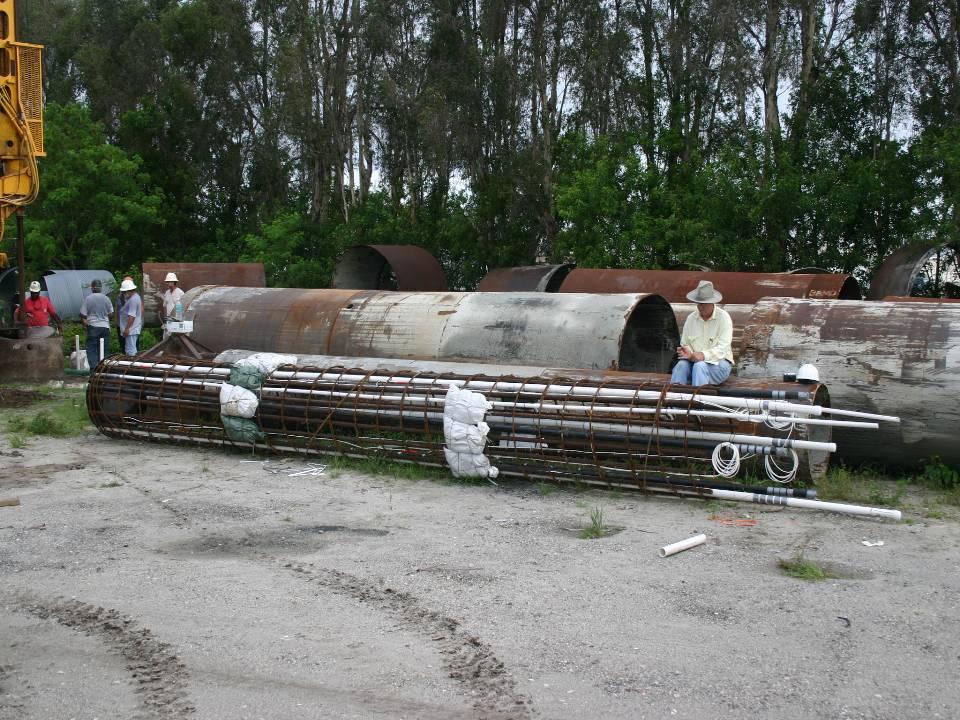
35


36 Instrumentation 16 Thermal Couples 2 Levels of 4 Strain Gages


37 Test Shaft 183F Peak Core Logging Tubes Reinforcement Cage Logging tube 8ft from edge Logging tube 1ft from edge

 10 15 6:00 AM")

38 0 Thermal Logging Tube 1 Temperature (V) CSL Logging Tubes Thermal Logging Tubes :00 PM 12:00 AM A 3:00 AM Depth (ft) :00 AM 9:00 AM B Known Anomalies Steel Logging Tubes Known Anomaly 5 3 PVC Logging Tubes 5 3 Cross-Section A Top Anomaly Cross-Section B Bottom Anomaly

39 Signal Matched Results

40 Cross-hole Sonic Logging


41 Cross-hole Sonic Logging Results Tubes 4-6 Tubes 2-4 Tubes A B Cross-Section A Top Anomaly Cross-Section B Bottom Anomaly CSL Logging Tubes Thermal Logging Tubes 6 2 Steel Logging Tubes Known Anomaly 6 2 PVC Logging Tubes 4 4


42 Pile Integrity Testing
43 Pile Integrity Test Results Second anomaly (16 ft) not detected Known Anomaly (approx. 8 ft down)
44 Thermal Integrity Evaluation Field Measurements Model Soil / Shaft System Compare Predicted and Measured Signal Match Model Results Modeled shape determines amount/degree of anomalous conditions

45 St. Augustine Bridge of Lions

46 Bridge of Lions Pier 25 Shaft 3 3ft diameter
 -50-60 BOC 70 80 Model Results -70-80 Measured Results 90-90 100-100 Tube 1 Tube 2 110-110 Tube")
47 Temperature (deg F) Temperature (deg F) Depth (ft) Elevation (ft) BOC Model Results Measured Results Tube 1 Tube Tube 3
48 Bridge of Lions Concreting Curve
 -50-60 BOC Elevation (ft) 50 60-70 70-80 80-90 90 Tube 1-100 Tube 1 Tube 2 100 Tube 2 Tube 3-110 Tube 3")
49 0 Temperature (deg F) Temperature (deg F) Elevation (ft) BOC Elevation (ft) Tube Tube 1 Tube Tube 2 Tube Tube 3 110
50 Modeled Temperature (deg F) Measured Temperature (deg F) Sample Data Model Norm Depth (ft) Modeled Neck Model Norm Depth (ft) Tube1 Tube1 Tube2 Tube2 Tube3 Tube4 Tube3 Model Norm Tube4 Modeled Neck 30 30

51 1 Cage Alignment F Soil Temp 54" excavation 50F Soil Temp Temperature (F) " cage / tube diameter T3 T S1 S10 S19 S46 S37 S Position (in)


52 Cage Alignment

53 WSDOT Nalley Valley I-5/SR16
54 WSDOT Nalley Valley I-5/SR16 Modeled and Measured Core and Tube Temps ft up Temperature (deg F) Time (hrs) 26ft up 36ft up Air Model Center Model Cage
55 Pier 6 Shaft B Temperature (deg F) Depth (ft) 0 5 Top of Perm Casing Construction Joint Bottom of Perm Casing 9' Auger w/ 1' Reamer ' Digging Bucket w/ 2' Reamer ' Auger Elevation (ft) Avg Field Testing Model Normal T/C Data SP -SM / SP T N 33 SM / SP T N 42 SP -SM / SP T N 73 SM / SP T N 56 SP -SM / SP T N 78 SW-SM / SP T N ' Cleanout Bucket Bottom of Shaft SM / SP T N 84
56 Temperature (deg F) Cage Alignment T1_ T2_2 T3_2 Tube Stickup 30 T4_2 Depth (ft) T5_2 T6_2 Water Table Sloughing 45 T7_2 50 T8_ T9_2 T10_2 Tube No Average Tube No. 1 75
57 Temperature (deg F) Cage Alignment T1_ ft T2_2 T3_2 N Increasing Tube Nos. 30 T4_2 TUBE 1 Depth (ft) T5_2 T6_2 T7_2 T8_ T9_2 T10_2 Average 125F 150F 175F 25 ft 75
58 Temperature (deg F) Cage Alignment T1_ T2_2 T3_2 N Increasing Tube Nos ft T4_2 TUBE 1 Depth (ft) T5_2 T6_2 T7_2 T8_ T9_2 T10_2 Average 125F 150F 175F 30 ft 75
59 Temperature (deg F) Cage Alignment T1_ T2_2 T3_2 N Increasing Tube Nos. 30 T4_2 TUBE 1 Depth (ft) ft T5_2 T6_2 45 T7_2 50 T8_ T9_2 T10_2 Average 125F 150F 175F 35 ft 75
60 Temperature (deg F) Cage Alignment T1_ T2_2 T3_2 N Increasing Tube Nos. 30 T4_2 TUBE 1 Depth (ft) ft T5_2 T6_2 45 T7_2 50 T8_ T9_2 T10_2 Average 125F 150F 175F 40 ft 75
61 Temperature (deg F) Cage Alignment T1_ T2_2 T3_2 N Increasing Tube Nos. 30 T4_2 TUBE 1 Depth (ft) T5_2 T6_ ft T7_2 50 T8_ T9_2 T10_2 Average 125F 150F 175F 45 ft 75
62 Temperature (deg F) Cage Alignment T1_ T2_2 T3_2 N Increasing Tube Nos. 30 T4_2 TUBE 1 Depth (ft) T5_2 T6_ ft T7_2 T8_ T9_2 T10_2 Average 125F 150F 175F 50 ft 75
63 Temperature (deg F) Cage Alignment T1_ T2_2 T3_2 N Increasing Tube Nos. 30 T4_2 TUBE 1 Depth (ft) T5_2 T6_2 T7_ ft T8_2 T9_2 T10_2 Average 125F 150F 175F 55 ft 75
64 Temperature (deg F) Cage Alignment T1_ T2_2 T3_2 N Increasing Tube Nos. 30 T4_2 TUBE 1 Depth (ft) T5_2 T6_2 T7_2 T8_ ft T9_2 T10_2 Average 125F 150F 175F 60 ft 75
65 Temperature (deg F) Cage Alignment T1_ T2_2 T3_2 N Increasing Tube Nos. 30 T4_2 TUBE 1 Depth (ft) T5_2 T6_2 T7_2 T8_ ft T9_2 T10_2 Average 125F 150F 175F 65 ft 75
66 Temperature (deg F) Cage Alignment T1_ T2_2 T3_2 N Increasing Tube Nos. 30 T4_2 TUBE 1 Depth (ft) T5_2 T6_2 T7_2 T8_ ft T9_2 T10_2 Average 125F 150F 175F 70 ft 75
67 Cage Alignment (at 40 ft) Depth 40 ft Highest Measured Temp Worst Case Cover (7.5in) Temperature (F) Lowest Measured Temp Lateral Temp Dist (model) Cage Diameter at tubes Excavation Diameter Horizontal Position
68 Thermal Testing Timeframe 4000 P Mix Design 160 4ft Diameter 6ft Diameter 8ft Diameter ft Diameter Temperature (deg F) Optimal Testing Window Acceptable Testing Window Time (hrs)
69 Conclusions Infra-red Thermal Integrity testing shows remarkable capabilities to detect anomalies outside the reinforcing cage (bulges and necks) Cross-hole Sonic Logging showed no problems with the shaft integrity in spite serious cross sectional reduction Pile Integrity Testing showed an irregularity of unknown proportion at one of the two anomaly locations but not the second
70 Conclusions Cage alignment is easily identified and can confirm minimum cover / cage alignment Thermal modeling provides insight into a normal shaft signature as well as mass concrete conditions Thermal models can be signal matched field measurements to ascertain location and size of anomalies.

 759-2426 Fax: (813) 759-2427")

71 Home About FGE Services Projects Contact 712 East Alsobrook Street, Suite 3 Plant City, FL Office: (813) Fax: (813) engineering@foundations.cc Infrared Integrity Services available at
Thermal Integrity Profiling
 Thermal Integrity Profiling Quality Assurance Test Method to Detect Drilled Shaft Defects Gray Mullins, Ph.D., P.E. Professor, University of South Florida AFS30 Committee Meeting, TRB 2011 Overview Thermal
Quality Control of Drilled Piles
 Quality Control of Drilled Piles (Drilled Shafts, Bored Piles, Augercast piles) Garland Likins, P.E. Pile Dynamics, Inc. August 2015 2015, Pile Dynamics, Inc. For a pile to successfully carry the required
Non-Destructive Testing of Drilled Shafts Current Practice and New Method
 Non-Destructive Testing of Drilled Shafts Current Practice and New Method George Piscsalko PE, Pile Dynamics, Inc., Cleveland, Ohio, USA Garland Likins PE, Pile Dynamics, Inc., Cleveland, Ohio, USA Benjamin
Using Thermal Integrity Profiling to Confirm the Structural Integrity of foundation applications
 Using Thermal Integrity Profiling to Confirm the Structural Integrity of foundation applications Authors: 1. George Piscsalko, PE, Pile Dynamics, Inc., 30725 Aurora Road, Solon, Ohio, USA, gpiscsalko@pile.com;
Where WVDOH is at with Mass Concrete
 Where WVDOH is at with Mass Concrete History of Mass Concrete and the WVDOH In 2005, a large bridge crossing the Ohio River was being constructed (Blennerhassett Bridge) Because of the large size of some
SAMPLE SPECIFICATION for CROSSHOLE SONIC LOGGING (CSL) September 2015
 September 2015") SAMPLE SPECIFICATION for CROSSHOLE SONIC LOGGING (CSL) September 2015 Note: This sample specification contains recommended or typical quantities in parenthesis, in the format (quantity); the specifying
SAMPLE SPECIFICATION for CROSSHOLE SONIC LOGGING (CSL) September 2015 Note: This sample specification contains recommended or typical quantities in parenthesis, in the format (quantity); the specifying
Recent Developments in the Axial, Lateral and Torsional Response of Drilled Shaft Foundations
 Recent Developments in the Axial, Lateral and Torsional Response of Drilled Shaft Foundations Armin W. Stuedlein, PhD P.E. Associate Professor Geotechnical Engineering Presentation Outline Motivation and
THE USE OF SELF-CONSOLIDATING CONCRETE FOR DRILLED SHAFT CONSTRUCTION: PRELIMINARY OBSERVATIONS FROM THE LUMBER RIVER BRIDGE FIELD TRIALS
 1 THE USE OF SELF-CONSOLIDATING CONCRETE FOR DRILLED SHAFT CONSTRUCTION: PRELIMINARY OBSERVATIONS FROM THE LUMBER RIVER BRIDGE FIELD TRIALS Dan Brown 1, Joe Bailey 2, Anton Schindler 3 ABSTRACT: Several
CONTINUOUS FLIGHT AUGER (CFA) PILES QC/QA PROCEDURES. Preferred QC/QA Procedures
 PILES QC/QA PROCEDURES. Preferred QC/QA Procedures") Preferred QC/QA Procedures The Federal Highway Administration (FHWA) has provided QC/QA guidance for this technology as noted below. The reference document also contains information about construction
Preferred QC/QA Procedures The Federal Highway Administration (FHWA) has provided QC/QA guidance for this technology as noted below. The reference document also contains information about construction
CONTRACTOR AND EQUIPMENT ARRIVE ON-SITE
 Lesson 5 Inspector CONTRACTOR AND EQUIPMENT ARRIVE ON-SITE Drilled Shaft Installation Plan 5-1 Version 1-1/15 5-1 Learning Outcomes Identify and understand the Role and Duties of the Inspector Verify and
Case Histories Utilizing Thermal Integrity Profiling for Foundation Quality Assurance
 Case Histories Utilizing Thermal Integrity Profiling for Foundation Quality Assurance Marty Bixler, P.Eng., P.E. GRL Engineers, Inc., Maple Valley, Washington, U.S.A. Daniel Belardo GRL Engineers, Inc.,
Integrity evaluation of concrete by cross-hole sonic logging in Bangladesh
 IABSE-JSCE Joint Conference on Advances in Bridge Engineering-III, August 2-22, 25, Dhaka, Bangladesh. ISBN: 978-984-33-933-5 Amin, Okui, Bhuiyan, Ueda (eds.) www.iabse-bd.org Integrity evaluation of concrete
Lesson 7 REINFORCING CAGE. Version 1-1/
 Lesson 7 REINFORCING CAGE 7-1 Version 1-1/15 7-1 Learning Outcomes Describe cage construction Determine the circumference of a shaft and rebar cage and calculate the required number of side spacers. Explain
Drilled Shaft. Inspection. HQ Construction Office HQ Geotechnical Division
 Drilled Shaft Inspection HQ Construction Office HQ Geotechnical Division Drilled Shafts: What are Drilled Shafts Drilled Shaft Construction Challenges of Drilled Shaft Construction The WSDOT SHAFT Special
Rapid Axial Load Testing of Drilled Shafts
 Supplemental Technical Specification for Rapid Axial Load Testing of Drilled Shafts SCDOT Designation: SC-M-712 (9/15) September 4, 2015 1.0 GENERAL This work shall consist of performing a rapid axial
Implementation of this Special Provision requires a complete understanding of the following documents:
 VIRGINIA DEPARTMENT OF TRANSPORTATION SPECIAL PROVISION FOR Quality Assurance/Quality Control (QA/QC) for the Construction of Deep Foundation Systems for Design-Build and PPTA Contracts November 10, 2009
STRUCTURES SPECIFICATIONS FOR BRIDGE CONSTRUCTION ISSUES. John Westphal, P.E. State Construction Office January 2017
 STRUCTURES SPECIFICATIONS FOR BRIDGE CONSTRUCTION ISSUES John Westphal, P.E. State Construction Office January 2017 Introduction Discuss Defective Materials, as defined within the Specifications Recent
CHANGES IN 2006 SPECIFICATIONS SECTION 804 DRIVEN PILES SECTION 814 DRILLED SHAFTS
 CHANGES IN 2006 SPECIFICATIONS SECTION 804 DRIVEN PILES SECTION 814 DRILLED SHAFTS 2006 LADOTD ENGINEERING CONFERENCE Kim Martindale Garlington, P.E. Pavement & Geotechnical Services February 13, 2007
INDOT/ACPA Technical Committee 2009 Specification Revisions 2009 Test Method Revisions Studies
 PCCP Workshop INDOT INDOT/ACPA Technical Committee 2009 Specification Revisions 2009 Test Method Revisions Studies INDOT/ACPA Technical Committee Materials Management FHWA Construction Management District
OKLAHOMA DEPARTMENT OF TRANSPORTATION SPECIAL PROVISION FOR DRILLED SHAFT FOUNDATIONS
 516-3(a-s) 09 OKLAHOMA DEPARTMENT OF TRANSPORTATION SPECIAL PROVISION FOR DRILLED SHAFT FOUNDATIONS These Special Provisions revise, amend, and where in conflict, supersede applicable sections of the 2009
RECORD KEEPING AND INSPECTION NOTES FOR FUTURE NEEDS
 RECORD KEEPING AND INSPECTION NOTES FOR FUTURE NEEDS Chris Nickel, P.E. LA DOTD Pavement & Geotechnical Services 2011 Louisiana Engineering Conference TOPIC OUTLINE Driven Piles Definitions and Data table
Bi-Directional Static Load Testing of Drilled Shafts
 Supplemental Technical Specification for Bi-Directional Static Load Testing of Drilled Shafts SCDOT Designation: SC-M-712 (01/18) 1.0 GENERAL This work shall consist of furnishing all materials, equipment,
Bi-Directional Static Load Testing of Driven Piles
 Bi-Directional Static Load Testing of Driven Piles Paul J. Bullock, PhD Fugro Consultants Inc. Loadtest Bi-Directional Osterberg Cell Testing Specialized jack in pile uses bearing to mobilize side shear
Response of Full Scale Drilled Shafts in Loose Soils Exposed to Induced Vibrations
 Tenth LACCEI Latin American and Caribbean Conference (LACCEI 2012), Megaprojects: Building Infrastructure by fostering engineering collaboration, efficient and effective integration and innovative planning,
SUPPLEMENTAL TECHNICAL SPECIFICATION
 July 14, 2015 HIGH STRAIN DYNAMIC LOAD TESTING OF DRILLED SHAFTS 1.0 GENERAL This work shall consist of performing high-strain dynamic testing using a drop weight loading system on a test drilled shaft
DETERMINATION OF REQUIRED INSULATION FOR PREVENTING EARLY-AGE CRACKING IN MASS CONCRETE FOOTINGS
 Tu A. Do, Adrian M. Lawrence, Mang Tia, and Michael J. Bergin 0 0 0 0 DETERMINATION OF REQUIRED INSULATION FOR PREVENTING EARLY-AGE CRACKING IN MASS CONCRETE FOOTINGS Tu A. Do Post-Doctoral Associate Dept.
FHWA-NDE CENTER. Methods Available for Testing & Evaluation of Structures. NDE Center Federal Highway Administration
 FHWA-NDE CENTER Methods Available for Testing & Evaluation of Structures FHWA Current Projects Ultrasonic NDE Ground Penetrating Radar, PERES II Thermal NDE Laser System Measurements Load Testing Bridge
HIGH PERFORMANCE CONCRETE. by John J. Roller CTLGroup
 HIGH PERFORMANCE CONCRETE by John J. Roller CTLGroup Early Louisiana HPC Research Law & Rasoulian (1980) Adelman & Cousins (1990) Bruce, Russell & Roller (1990-1993) Law & Rasoulian (1980) Concrete strengths
Aggregate Optimization. Quality Assurance Workshop February Justin Bryan. Frank Bryan Inc. Bryan Materials Group
 Aggregate Optimization Quality Assurance Workshop February 2017 Justin Bryan Frank Bryan Inc. Bryan Materials Group Outline Background on Aggregate Optimization Utilization of Optimized Aggregate Mixes
Steven Dapp, Ph.D., P.E. Steven Dapp, Ph.D., P.E. Dan Brown and Associates
 LA Transportation Conference: 10 Jan 2011 Drilled Shaft Foundations For Two Mississippi River Bridges in Louisiana Dan Brown and Associates Projects John James Audubon Bridge, St. Francisville New Construction
SAMPLE GUIDE SPECIFICATIONS FOR OSTERBERG CELL LOAD TESTING OF DRILLED SHAFTS
 SAMPLE GUIDE SPECIFICATIONS FOR OSTERBERG CELL LOAD TESTING OF DRILLED SHAFTS 1.0 DESCRIPTION This work shall consist of furnishing all materials and labor necessary for conducting an Osterberg Cell (O-cell)
NEW PERFORMANCE CRITERIA FOR FRESH TREMIE CONCRETE
 NEW PERFORMANCE CRITERIA FOR FRESH TREMIE CONCRETE Karsten Beckhaus (1), Martin Larisch (2), Habib Alehossein (3,4) (1) BAUER Spezialtiefbau GmbH, Deutschland (2) Keller Australia Pty Ltd, Australia (3)
INNOVATIVE PILE EXTRACTION TECHNIQUE OF CFA PILES FOR THE NEW HARBOR BRIDGE PROJECT
 INNOVATIVE PILE EXTRACTION TECHNIQUE OF CFA PILES FOR THE NEW HARBOR BRIDGE PROJECT Tracy Brettmann, P.E., D.GE, Vice President, A. H. Beck Foundation Company, Houston, Texas, (713) 413-3800, tracy.brettmann@ahbeck.com
EXPERIENCES WITH BASE GROUTED DRILLED SHAFTS IN THE
 EXPERIENCES WITH BASE GROUTED DRILLED SHAFTS IN THE SOUTHEASTERN UNITED STATES Steven D. Dapp, Ph.D., P.E., Dan A. Brown and Associates, Sequatchie, Tennessee, U.S.A. Mike Muchard, P.E., Applied Foundation
SECTION XXXXX AGGREGATE PIERS PART 1 - GENERAL
 SECTION XXXXX AGGREGATE PIERS PART 1 - GENERAL 1.1 RELATED DOCUMENTS: Drawings and general provisions of the Contract, including General and Supplementary Conditions and other Division 00 and Division
UNDERPINNING A CRANE FOUNDATION
 UNDERPINNING A CRANE FOUNDATION Donald R. McMahon, P.E., McMahon & Mann Consulting Engineers, P.C., Buffalo, New York, USA Andrew J. Nichols, P.E., McMahon & Mann Consulting Engineers, P.C., Buffalo, New
REQUIREMENTS FOR CONCRETE MIX DESIGN
 REQUIREMENTS FOR CONCRETE MIX DESIGN Requirements of concrete mix design should be known before calculations for concrete mix. Mix design is done in the laboratory and samples from each mix designed is
Mass Concrete. Questions related to specific materials, methods, and services will be addressed at the conclusion of this presentation.
 Mass Concrete How big is big? Bob Howell May 19, 2017 American Concrete Institute is a Registered Provider with The American Institute of Architects Continuing Education Systems (AIA/CES). Credit(s) earned
Latex Modified Mortar or Concrete Wearing Course
 PennDOT Engineering District 8-0 Latex Modified Mortar or Concrete Wearing Course Publication 408 Section 1042 Justin M. Enck, E.I.T. Civil Engineer Structure Control Unit District 8-0 juenck@pa.gov Latex
PAUL ZICK, PE NORTH SHORE CONSTRUCTORS JV
 NORTH SHORE CONNECTOR TUNNELS AND STATION SHELL LIGHT RAIL PROJECT PAUL ZICK, PE NORTH SHORE CONSTRUCTORS JV North Shore Connector Alignment 7300 lf Extension to existing 25 mile system 18 Contracts $435
Recent Advances in the Selection and Use of Drilled Foundations
 Recent Advances in the Selection and Use of Drilled Foundations Dan Brown, P.E., Ph.D. Dan Brown and Associates Overview Micropiles Continuous Flight Auger Piles Drilled Displacement Piles Drilled Shafts
Seismic Analysis of Concrete Dams Workshop USSD Annual Conference April 6-7, 2017
 Workshop 2017 USSD Annual Conference April 6-7, 2017 Seismic Analysis of Concrete Dams Selection of analysis Selection of Materials Properties Properties affected by state of the art for materials, mix
Evaluation of Performance Based Concrete For Bridge Decks. DeWayne Wilson WSDOT Bridge Asset Management Engineer
 Evaluation of Performance Based Concrete For Bridge Decks DeWayne Wilson WSDOT Bridge Asset Management Engineer National Concrete Consortium Columbus, Ohio 4/26/2016 Problem - WSDOT has observed abnormal
5.0 DRILLED SHAFTS. Table of Contents
 5.0 DRILLED SHAFTS Table of Contents 5.0 DRILLED SHAFTS...1 5.4.1 General...1 5.4.2 Bid Items:...2 5.4.3 Equipment:...3 5.4.4 Materials:...5 5.4.5 Investigative Core Hole:...6 5.4.6 Drilling (Excavation):...6
EVALUATION OF SELF-CONSOLIDATING CONCRETE FOR DRILLED SHAFT APPLICATIONS AT THE LUMBER RIVER BRIDGE PROJECT, SOUTH CAROLINA
 Research Report No. 2 EVALUATION OF SELF-CONSOLIDATING CONCRETE FOR DRILLED SHAFT APPLICATIONS AT THE LUMBER RIVER BRIDGE PROJECT, SOUTH CAROLINA Submitted to S&ME Inc. Mt. Pleasant, South Carolina Prepared
JANUARY 4, 2017 AT 2:00 P.M. (EASTERN. (Estimated Cost: $4,600,000) Bids J D WILLIAMSON CONSTRUCTION CO INC $3,799,476.25
 Bids J D WILLIAMSON CONSTRUCTION CO INC $3,799,476.25") General Info Number: PROJECT NO. 43-17-03 Description: BRIDGE DECK REPAIR AND REHABILITATION, ARLINGTON ROAD OVER OHIO TURNPIKE M.P. 122.3, JOPPA ROAD OVER OHIO TURNPIKE M.P. 128.5, DEAN ROAD OVER OHIO
General Info Number: PROJECT NO. 43-17-03 Description: BRIDGE DECK REPAIR AND REHABILITATION, ARLINGTON ROAD OVER OHIO TURNPIKE M.P. 122.3, JOPPA ROAD OVER OHIO TURNPIKE M.P. 128.5, DEAN ROAD OVER OHIO
SPECIFICATIONS FOR PRECAST MODULAR BLOCK RETAINING WALL SYSTEM (revised 5/8/7)
") Page 1 of 7 STONE STRONG SYSTEMS SPECIFICATIONS FOR PRECAST MODULAR BLOCK RETAINING WALL SYSTEM (revised 5/8/7) PART 1: GENERAL 1.01 Description A. Work includes furnishing and installing precast modular
Page 1 of 7 STONE STRONG SYSTEMS SPECIFICATIONS FOR PRECAST MODULAR BLOCK RETAINING WALL SYSTEM (revised 5/8/7) PART 1: GENERAL 1.01 Description A. Work includes furnishing and installing precast modular
Rapid Overlays for Deck Preservation Virginia Concrete Conference Richmond, Virginia March 8-9, 2012
 Rapid Overlays for Deck Preservation Virginia Concrete Conference Richmond, Virginia March 8-9, 2012 Michael M. Sprinkel, P.E. Associate Director Virginia Center for Transportation Innovation & Research
FHWA Mobile Concrete Lab Program. Illinois Tollway Open House: Sustainable Concrete Paving Practices August 20, 2013
 FHWA Mobile Concrete Lab Program Illinois Tollway Open House: Sustainable Concrete Paving Practices August 20, 2013 Mission Tech Transfer to SHA s Field demos on active projects Equipment loan Training
FB-MULTIPIER: P-Y MODEL VALIDATION
 FB-MULTIPIER: P-Y MODEL VALIDATION FB-MultiPier V4.19 vs. LPILE V6.0.15 July 2014 Jae Chung, Ph.D. Anand Patil, E.I. Henry Bollmann, P.E. Bridge Software Institute 1 EXECUTIVE SUMMARY This report summarizes
ADIABATIC TEMPERATURE RISE AND REACTION RATE OF MASS STRUCTURE IN LOTTE CENTER HANOI PROJECT
 ADIABATIC TEMPERATURE RISE AND REACTION RATE OF MASS STRUCTURE IN LOTTE CENTER HANOI PROJECT Dr. KIM KWANG KI, Eng. HWANG IN GWAN, Eng. KIM MYOUNG GUG Lotte E&C, Lotte Center Hanoi Project Abstract: It
Reinforced Concrete Column Design
 Reinforced Concrete Column Design Compressive Strength of Concrete f cr is the average cylinder strength f c compressive strength for design f c ~2500 psi - 18,000 psi, typically 3000-6000 psi E c estimated
EVALUATION OF HIGH-PERFORMANCE DRILLED SHAFT CONCRETE IN THE B.B. COMER BRIDGE
 Research Report EVALUATION OF HIGH-PERFORMANCE DRILLED SHAFT CONCRETE IN THE B.B. COMER BRIDGE Submitted to The Alabama Department of Transportation Prepared by Phillip A. Gallet, Anton K. Schindler, and
NRMCA is working on. Experimental Case Study Demonstrates Advantages of Performance Specifications
 Experimental Case Study Demonstrates Advantages of Performance Specifications By Karthik Obla, Director of Research and Materials Engineering Fernando Rodriguez, Laboratory Manager and Soliman Ben Barka,
Geothermal Tunnel Linings. Principles of Geothermal Tunnel Linings
 Geothermal Tunnel Linings Principles of Geothermal Tunnel Linings Duncan Nicholson - Director, Ove Arup and Partners Limited 11.00 11.30hrs 18 October 2012 Contents Background Ground source heat energy
PASSAIC COUNTY TECHNICAL INSTITUTE CCA 1422 NEW S.T.E.M. BUILDING 2017
 SECTION 02630 - STORM DRAINAGE PART 1 - GENERAL 1.1 RELATED DOCUMENTS A. Drawings and general provisions of the Contract, including General and Supplementary Conditions and Division 01 Specification Sections,
Pressure Grouting Drilled Shaft Tips: Full-Scale Research Investigation for Silty and Shelly Sands. Steven D. Dapp* and Gray Mullins**
 Pressure Grouting Drilled Shaft Tips: Full-Scale Research Investigation for Silty and Shelly Sands Steven D. Dapp* and Gray Mullins** *Graduate Researcher, University of South Florida, Department of Civil
Concrete Shrinkage Testing and Challenges
 Concrete Shrinkage Testing and Challenges Presented by Jafar Allahham MS student University of Utah NC2 Meeting April 26 th, 2017 Little America Hotel Acknowledgements Others at Univ. of Utah Assisting
Negative Skin Friction Aaron S. Budge, Ph.D., P.E. Minnesota State University, Mankato
 Negative Skin Friction Aaron S. Budge, Ph.D., P.E. Minnesota State University, Mankato A QUICK ITEM OF INTEREST Mn/DOT-funded survey to State DOT s 41 out of 50 States eventually responded (with some prodding!)
VDOT s New High Performance Concrete Specifications
 VDOT s New High Performance Concrete Specifications Celik Ozyildirim, Ph.D., P.E. A partnership of the Virginia Department of Transportation and the University of Virginia since 1948 3/4/2010 1 HPC in
INNOVATIVE SLOPE STABILISATION BY USING ISCHEBECK TITAN SOIL NAILS
 Dipl.-Wirt.Ing. Oliver Freudenreich Friedr. Ischebeck GmbH phone: ++49 2333 8305-0 Loher Str. 31 79 fax: ++49 2333 8305-55 e-mail: freudenreich@ischebeck.de D-58256 Ennepetal www.ischebeck.com INNOVATIVE
UNIFORM STANDARD DRAWINGS CLARK COUNTY AREA, NEVADA YEAR 2015 REVISIONS
 , NEVADA YEAR 2015 REVISIONS SECTION TITLE AND REVISIONS SUMMARY EFFECTIVE DATE 217.S2 "Residential Curb and Gutter, R-Type" - New drawing to accommodate ADA requirements. 223 "Residential Driveway" -
INSTALLATION OF AIRFIELD LIGHTING UNDERGROUND ELECTRICAL DIRECTIONAL BORE DUCT
 UNDERGROUND ELECTRICAL PART 1 GENERAL 1.1 SECTION INCLUDES: A. The work specified in this section consists of furnishing and installing underground utilities using the method of installation commonly referred
DETERMINATION OF THE LONG-TERM PROPERTIES FOR MIRAGRID XT GEOGRIDS
 DETERMINATION OF THE LONG-TERM PROPERTIES FOR MIRAGRID XT GEOGRIDS Prepared by: TenCate Geosynthetics Americas 365 South Holland Drive Pendergrass, GA 30567 Tel 706 693 2226 Fax 706 693 4400 www.tencate.com
Non-Delayed Heat Application Effects on The Strength of Concrete For Railway Sleepers
 www.crl.issres.net Vol. 5(1) - March 2014 Non-Delayed Heat Application Effects on The Strength of Concrete For Railway Sleepers Rasiah Sri Ravindrarajah 1 and Stephen R. White 2 1 School of Civil and Environmental
ENGINEERING MATERIALS Assignment #8: Concrete Mix Design
 14.310 ENGINEERING MATERIALS Assignment #8: Concrete Mix Design PROBLEM #1: GIVEN: Concrete is required for a pavement slab that will be exposed to severe freeze-thaw climate as well as deicing chemicals.
Properties of Concrete. Properties of Concrete. Properties of Concrete. Properties of Concrete. Properties of Concrete. Properties of Concrete
 CIVL 1112 Contrete Introduction from CIVL 1101 1/10 Concrete is an artificial conglomerate stone made essentially of Portland cement, water, and aggregates. While cement in one form or another has been
High Strength Epoxy Tested in Accordance with ICC-ES AC308
 ADHESIVE ANCHORING SPECIALISTS DESCRIPTION/SUGGESTED SPECIFICATIONS* The 100% epoxy resin and hardener are completely mixed as they are dispensed from the dual cartridge through a static mixing nozzle,
SPECIFICATION 1035 M
 MAY 1984 SPECIFICATION 1035 M SPECIFICATIONS FOR UNDERWATER CONCRETE 1035. 1. DESCRIPTION The work will consist of the mixing of concrete in accordance with the "Specifications for Reinforced Concrete",
Underwater Concrete in Drilled Shafts: the Key Issues and Case Histories
 Underwater Concrete in Drilled Shafts: the Key Issues and Case Histories Sam X. Yao 1 and Robert B. Bittner 2 ABSTRACT: In construction of drilled shafts under water, placing concrete in the shafts is
Types of Cracking and Influencing Causes
 Types of Cracking and Influencing Causes TRB Cracking Webinar May 25, 2016 R. Doug Hooton NSERC/ Cement Association of Canada, Senior Industrial Research Chair in Concrete Durability & Sustainability hooton@civ.utoronto.ca
Behavior of Reinforced Embankment on Soft Ground with and without Jet Grouted Soil-Cement Piles
 Behavior of Reinforced Embankment on Soft Ground with and without Jet Grouted Soil-Cement Piles by 1 Dennes T. Bergado and 2 Glen A. Lorenzo 1 Professor and 2 Doctoral Candidate, respectively Geotechnical
RESPONSE OF A FRESHLY PLACED FULL SCALE CONCRETE DRILLED SHAFT TO VIBRATIONS INDUCED BY ADJACENT SHAFT INSTALLATION
 RESPONSE OF A FRESHLY PLACED FULL SCALE CONCRETE DRILLED SHAFT TO VIBRATIONS INDUCED BY ADJACENT SHAFT INSTALLATION D.V. Reddy, Florida Atlantic University, USA C.S. Gonzalez-Mier, Florida Atlantic University,
Pavement Design and Construction of Taxilane S to Accommodate New Large Aircraft at LAX
 Pavement Design and Construction of Taxilane S to Accommodate New Large Aircraft at LAX Katie Chou, Ph.D., P.E. Hatch Mott MacDonald, Los Angeles Office Presented to: 2011 SWIFT Conference, Montreal Date:
Use of Grade 80 Reinforcement in Oregon
 Use of Grade 80 Reinforcement in Oregon Craig Shike, PE Bridge Operations & Standards Managing Engineer PRESENTATION OUTLINE Material Properties of High Strength Reinforcement Recent Grade 80 Research
SPECIAL SPECIFICATION 4900 Sacrificial Cathodic Protection Pile Jacket
 1993 Specifications CSJ 0331-04-045 SPECIAL SPECIFICATION 4900 Sacrificial Cathodic Protection Pile Jacket 1. Description. This Item shall govern for the furnishing, installing and energizing a sacrificial
Internal Curing. Improving Concrete Durability and Sustainability Using Internal Curing. Using Prewetted Lightweight Aggregates
 Internal Curing Using Prewetted Lightweight Aggregates Improving Concrete Durability and Sustainability Using Internal Curing Presented to: LA DOTD Transportation Conference February, 2013 Jeff Speck,
Application of Stress-Wave Theory to Piles
 PROCEEDINGS OF THE SIXTH INTERNATIONAL CONFERENCE ON THE APPLICATION OF STRESS-WAVE THEORY TO PILES / SAO PAULO / BRAZIL/ 11 13 SEPTEMBER 2000 Application of Stress-Wave Theory to s Quality Assurance on
Foundation Innovations Ensure Successful Bridge Replacement
 COVER STORY Foundation Innovations Ensure Successful Bridge Replacement Rhode Island s new $163.7 million, 2,265 ft (690 m) long, fourlane Sakonnet River Bridge sits just south of the existing bridge in
NTPEP Evaluation of Epoxy and Resin Based Adhesive Bonding Systems.
 Standard Practice for NTPEP Evaluation of Epoxy and Resin Based Adhesive Bonding Systems. AASHTO Designation: [Number] American Association of State Highway and Transportation Officials 444 North Capitol
SECTION FOUNDATION DRAINAGE
 SECTION 33 41 13 SPEC WRITER NOTES: Use this section only for NCA projects. Delete text between // // not applicable to project. Edit remaining text to suit project. PART 1 - GENERAL 1.1 SUMMARY A. Section
High Strength Epoxy Tested in Accordance with ICC-ES AC308
 ADHESIVE ANCHORING SPECIALISTS High Strength Epoxy Tested in Accordance with ICC-ES AC308 DESCRIPTION/SUGGESTED SPECIFICATIONS* The epoxy resin and hardener are completely mixed as they are dispensed from
Ohio Department of Transportation Division of Production Management Office of Geotechnical Engineering. Geotechnical Bulletin
 Ohio Department of Transportation Division of Production Management Office of Geotechnical Engineering Geotechnical Bulletin GB 2 SPECIAL BENCHING AND SIDEHILL EMBANKMENT FILLS Geotechnical Bulletin GB2
George V. Voinovich Bridge Project
 George V. Voinovich Bridge Project CCG2 Mass Concrete ODOT Background In larger concrete structural elements, the exterior surfaces exposed to air or water cool faster versus the interior core of the element
Performance of Ultra-Thin Whitetopping District 58. Neal West, P.E.
 Performance of Ultra-Thin Whitetopping District 58 Neal West, P.E. District 58 State Project 026-03-0036 FERRIDAY - RED GUM ROUTE US 65 CONCORDIA PARISH Contractors Prime Contractor: D&J Construction Co.,
MAINE TURNPIKE AUTHORITY ADDENDUM NO. 2 CONTRACT EXIT 44 SOUTHBOUND ON RAMP IMPROVEMENTS MILE 44.3
 MAINE TURNPIKE AUTHORITY ADDENDUM NO. 2 CONTRACT 2018.03 EXIT 44 SOUTHBOUND ON RAMP IMPROVEMENTS MILE 44.3 The following changes are made to the Proposal, Specifications, and Plans. PROPOSAL Proposal Sheets
Our Tour Stops. A Foundation Engineering gtrip down the Mississippi River. Dan Brown, P.E. Dan Brown and Associates 9/6/2010.
 A Foundation Engineering gtrip down the Mississippi River Dan Brown, P.E. Dan Brown and Associates Our Tour Stops I 35W Minneapolis US U.S. 61 Bridge, Hastings, MN New Mississippi River Bridge (I 70),
DESIGN-BUILD-TEST PROCESS FOR HIGH CAPACITY MICROPILES: CONSTRUCTION CASE STUDY ON DUTCHESS RAIL TRAIL BRIDGE FOUNDATIONS, POUGHKEEPSIE, NEW YORK
 ABSTRACT DESIGN-BUILD-TEST PROCESS FOR HIGH CAPACITY MICROPILES: CONSTRUCTION CASE STUDY ON DUTCHESS RAIL TRAIL BRIDGE FOUNDATIONS, POUGHKEEPSIE, NEW YORK James Barron 1, P.E., Thomas Hattala 2, P.E.,
MICHIGAN CONCRETE ASSOCIATION GUIDE FOR COLD WEATHER CONCRETING
 MICHIGAN CONCRETE ASSOCIATION GUIDE FOR COLD WEATHER CONCRETING MCA:SMW 1 of 6 10-25-11 For the purposes of this document and the MCA Special Provision for Cold Weather Concreting, cold weather is determined
WELCOME TO THE PILE DRIVING INSPECTOR COURSE
 Lesson 1 WELCOME TO THE PILE DRIVING INSPECTOR COURSE 1-1 Welcome to the Pile Driving Inspector Course. This is a course designed to assist students to understand the specifications and inspection practices
PRELIMINARY ENGINEERING DESIGN MEMORANDUM WATER TREATMENT PLANT FLOOD WALL TO PROTECT BACKWASH SETTLING BASIN CITY OF NEW BUFFALO, MI
 PRELIMINARY ENGINEERING DESIGN MEMORANDUM WATER TREATMENT PLANT FLOOD WALL TO PROTECT BACKWASH SETTLING BASIN CITY OF NEW BUFFALO, MI City of New Buffalo, MI Preliminary Engineering Design Memorandum Water
LMC Overlays For Bridge Deck Preservation 2011 Southeast Bridge Preservation Partnership Meeting, Raleigh NC April 13-15, 2011
 LMC Overlays For Bridge Deck Preservation 2011 Southeast Bridge Preservation Partnership Meeting, Raleigh NC April 13-15, 2011 Michael M. Sprinkel, P.E. Associate Director Virginia Center for Transportation
Sub-Systems Design Review
 Sub-Systems Design Review P14416 Concrete Arborloo Base October 29, 2013 Team Intro Member Victoria Snell (ISE) Evan Burley (ME) Joe Omilanowicz (ME) Mac Keehfus (ME) Anthony Deleo (ISE) Role Project Manager
Houston Community College 3200 Main Parking Garage November 15, 2010 Houston Community College
 SECTION 323113 - CHAIN LINK FENCES AND GATES PART 1 - GENERAL 1.1 RELATED DOCUMENTS A. Drawings and general provisions of the Contract, including General and Supplementary Conditions and Division 01 Specification
Mark L. Reno, P.E. September 11, 2015
 Ogden Ogden Siphon Canyon Pipe Siphon Suspension Structural Assessment Bridge Mark L. Reno, P.E. September 11, 2015 Seismic Retrofit of Designed in 1936 by U.S. Bureau of Reclamation 1,044 feet of 31.25
William R. Bennett Bridge. W.R. Bennett Bridge, Kelowna, B.C. Canada. July 2005 to December 2008
 William R. Bennett Bridge W.R. Bennett Bridge, Kelowna, B.C. Canada. July 2005 to December 2008 Contract Details Scope: Design & Build the new W.R. Bennett Floating Bridge & Decommission existing Okanagan
Drill Shaft Contractor and Equipment Arrive On-Site CBT Script
 Drill Shaft Contractor and Equipment Arrive On-Site CBT Script Welcome to the Drilled Shaft Inspector Course. This is Lesson 5, Contractor and equipment Arrive On-Site. To begin, select the start button
Pile Driving Analyzer (PDA) and CAPWAP Proven Pile Testing Technology: Principles and Recent Advances
 and CAPWAP Proven Pile Testing Technology: Principles and Recent Advances") Pile Driving Analyzer (PDA) and CAPWAP Proven Pile Testing Technology: Principles and Recent Advances Frank Rausche, Ph.D., P.E. Pile Dynamics, Inc. 2013 Louisiana Transportation Conference 1 Introduction
Pile Driving Analyzer (PDA) and CAPWAP Proven Pile Testing Technology: Principles and Recent Advances Frank Rausche, Ph.D., P.E. Pile Dynamics, Inc. 2013 Louisiana Transportation Conference 1 Introduction
PRECONSTRUCTION DESIGN MEMORANDUM CULVERT PIPE STRUCTURAL DESIGN CRITERIA FOR SCDOT FILL HEIGHT TABLES
 PRECONSTRUCTION DESIGN MEMORANDUM MEMO: SUBJECT: PCDM-05 CULVERT PIPE STRUCTURAL DESIGN CRITERIA FOR SCDOT FILL HEIGHT TABLES SUPERSEDES: Instructional Bulletin 2010-1 This memorandum outlines the structural
TECHNICAL SPECIAL PROVISION FOR CONCRETE REPAIRS. Financial Project ID , &
 TECHNICAL SPECIAL PROVISION FOR CONCRETE REPAIRS Financial Project ID 429140-1-52-01, 429140-2-52-01 & 428267-1-52-01 The official record of this Technical Special Provision is the electronic file signed