Ceiling Camera Lift 2015
|
|
|
- Ursula Harper
- 5 years ago
- Views:
Transcription

1 Ceiling Camera Lift
2 Contents Important Installation Notes 3 Control Settings 4 Installation 5 Physical Installation Top Mounting 6 Lift Connections / Connecting Power 8 Camera Mounting / Cabling 12 Insert Ceiling Tile 14 Pictures( Front, Left, Right, and Rear ) 15 Pictures ( Extended View ) 16 Lift Removal 17 Maintenance and Safety 17 Remote Control Operation and Programming 18 Recover Lift from LOWER LIMIT ACTIVATION 23 Troubleshooting Chart 24 Digital Remote Interface Schematic 25 Camera Lift theory of operation 26 Optional (RS232 Opt-9) 30 Camera Lift Wire Harness 32 2
3 Thanks for purchasing a Display Devices lift product. We re sure your customer will enjoy this lift for years to come. Our products are designed to be maintenance-free, saving you future service time. If you experience any difficulties, please contact us at Thank you for your support. Before starting Read all instructions before installation. Important Installation Notes CAUTION! The lift is heavy! Take proper safety precautions and get adequate help When raising the lift. Ensure the electrical outlet is readily accessible and complies with the lift and projector specifications for voltages and amperages. Check above the ceiling for obstructions (i.e. water pipes, wires, cables, duct work, extreme temperature variations, etc.) before beginning installation. Ensure the ceiling structure is capable of holding at least four times the combined weight of the lift and projector. This is a minimum requirement. Follow any local or state codes that apply to your specific area. Organize your mounting hardware and have the necessary tools on-hand before installation. Attach the projector, ceiling closure system, or other items to the lift only after the lift has been properly installed and tested. CAUTION: Anytime you are installing or performing maintenance on the lift, disconnect power at the receptacle or breaker/fuse panel, program the lift to MANUAL MODE, or activate the NO MOVEMENT switch on the side of the control box to prevent inadvertent movement of the lift. 3

4 CONTROL SETTINGS Prior to the physical installation, you must perform the following steps: 1. Be sure that there is no power attached when setting the DIP switches Set the DIP switches on the control box before you install the lift in the ceiling. 2. Refer to the chart below for proper configurations 3. The DIP switches are located under the small access panel on the Control Box on the Control Box attached to the frame. Use a 1/16 hex drive to open. 4. Set the Aux AC trigger (12-volt output) and the 12V out based on your system design. Control Box Dip Switch Settings NOTE: The factory default setting will not change for most installations. If you are going to use the 12V out or the Aux Ac Trigger then set the dip switches. SET DIP SWITCHES before you install the lift. Be sure there is no power connected to the lift. The control box is located inside the lift on the upper frame. Depending upon your lift model the location and orientation of the control box varies. Dip switches are located under the small access panel on the Control Box attached to the lift frame. Use a 1/16 Hex driver to open. ON OFF SW1 Aux AC Trigger (see SW2 below) Aux AC Trigger is on all the time SW2 Aux AC Trigger upon going down Aux AC Trigger at show position SW3 12V out turns off upon going up 12V out turns off at top position SW4 12V out turns on upon going down 12V out turns on at show position Dip Switch SW1: configuration only works in automatic mode. Set the 12 volt out and AUX AC Trigger based on your system design. ON OFF Default setting 4
5 INSTALLATION Mounting hardware is not provided. Be sure to have all your mounting hardware and tools readily accessible before installation. Consult your local building codes for proper structural attachment. Here are the tools you will need: Safety glasses Socket set with 7/16 socket wrench Box wrenches 1/16 hex drive Philips Head Screwdriver Adjustable wrench Magnetic torpedo level (two, if possible) Ladders or manlift Genie Lift, or heavy straps and pulleys (for DataLift and DataLite Models) Knockout kit or hole saw ½ drill and/or ½ hammer drill 5

6 PHYSICAL INSTALLATION TOP-MOUNTING Top mounting is typically used when installing the lift into a false ceiling (grid tile) or an exposed unfinished ceiling. We recommend you install mounting hardware into a structural channel. Example Top Mounting Structural channel provides flexibility for adjusting the lift front-to-rear and sideto-side. All hardware should be at least in 3/8 (M10) diameter. You should use angled stabilizers if threaded rods extend 2 (60 cm) or more between structural channel and the lift. You should also leave the threaded rods slightly loose to ease in alignment and leveling after installing the lift. You need to make sure all hardware is securely tightened at the end of your installation. 6
7 PHYSICAL INSTALLATION TOP-MOUNTING (Continued) 1.) Plenum installations - attach the plenum enclosure to the 8 studs on the lift s upper frame. Add flat washer, split lock washer and M6 nuts tighten. 2.) Before you begin, be sure the threaded mounting rods have a nut, split and flat washer above the lift frame, and a flat washer and nut below the frame. These can be temporarily held in place with tape or chewing gum. 3.) Raise the lift into position and add hardware. Follow the hardware order below to ensure stability and accuracy when leveling the lift. Upper lift frame Nut Lock Washer Flat Washer Flat Washer Nut Note: The following are some of the most important steps in proper lift installation! Use a torpedo or bubble level to level the top frame of the lift. You may want to use more than one. 1. Level the lift from the right-front to the left-front. 2. Level the lift from left-front to left-rear. 3. Level the lift from left-rear to right-rear. 4. Recheck. 5. Tighten all hardware. 4.) Adjust the height by loosening the four Hex Head Screws, slide the enclosure box to the proper vertical height, and retighten. 5.) Determine the best location for power, control and signal cables to enter the lift enclosure. Use a knockout tool or drill holes in the plenum enclosure for cables. We recommend using flex conduit to the enclosure. 7


8 Lift Connections / Connecting Power Verify the voltage of the lift and the voltage of the camera. You can now connect the lift s power cord to a properly rated electrical circuit in the ceiling near the lift. The lift ships with a 3 foot IEC to Edison cord, and the IEC plugs in to the power module on the control box The Junction box termination is done by the electrician supplied by the customer. Follow the electrical codes in your area. The Edison plug can be plugged in to a receptacle on a junction box or hard wired in to the junction box. If a hole is drilled in the plenum for the junction box it will have to be sealed to maintain the plenum rating of the lift. There is one Junction box included for a hard wired configuration, and the junction box is shown below. 8


9 Note: Motor label 110V and the control box Label 120VAC Plug the hard wired push button remote in to one of the DB9 connectors labeled Remote 1 or Remote2. Both of the contact closer DB9 ports are in parallel, so it don t matter which port you use. 9

10 If the hand held remote is not easily accessible then it should be extended with all 9 wires, so the service technician can easily have all the functions available to trouble shoot the lift. Follow the digital interface schematic for color codes, or make sure you wright down the color codes used. Tighten the cable / stain relief connectors, if required After following these precautions, you are now ready to turn on the power switch on the lift control box. On the side of the control box, you will find a small black slider switch labeled NO MOVEMENT. The lift is shipped from the factory with the NO MOVEMENT switch in the ON position. When the slide switch is in the NO MOVEMENT location the control box will continuously blink and all functions will be disabled. The control box is mounted so the no movement slider switch is toward the back of the lift. Flip the NO MOVEMENT switch to the off position, and the led will stop blinking. If you cycle lift power the LED will blink twice and then stop blinking. Under Normal conditions the LED will not blink, and the LED will start to blink in a sequence only under and error condition. 10
 hand held remote control. For this installation, here is a guide to the lift error conditions.")
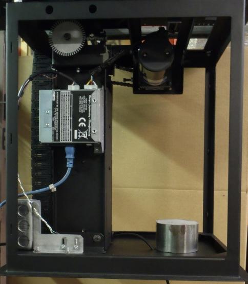
11 Caution! Make sure all tools, cables and body parts are clear of the lift before pushing the UP button. With the hand-held remote control, press the UP button to send the lift to the home position. Refer to the instructions later in this manual for control of the lift using the (enclosed) hand held remote control. For this installation, here is a guide to the lift error conditions. The LED on the control box and the hand held remote will blink in a numbered sequence shown for below If the LED Is Continuously Blinking Blinks twice (after unit is powered up, LED then stops blinking Blinks three times It means The NO MOVEMENT switch on the side of the control box is activated. This disables all movement of the lift. The lift is operational Fix it by Moving the switch to the OFF position Dual motor current Call DDI technical support problems* Blinks four times Motor is not moving Check the power to the motor or for a mechanical obstruction on the lift Blinks five times ** Low AC line voltage Check circuit voltage Blinks six times Cables off the drum Re-cable the drum(s) Blinks seven times Lower limit safety switch activated Follow steps on page 7 of the remote instructions AC Configuration DIP Switches Circuit Breaker AC Trigger AC Input Remote Control Input Ports 12VDC Out No Movement Switch Main Power Switch 12VDC In 11


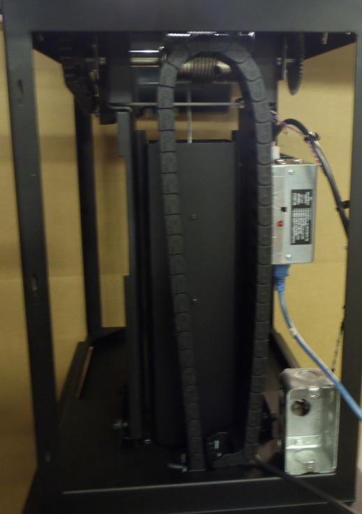
12 Camera Mounting / Cabling Use the hand-held remote control to lower the lift to the down position. Install the camera in the desired position using the enclosed adhesive Velcro. Follow the procedure below to install the cables in the energy chain Cable track entry point Cable track exit point 12


13 Remove the cable track from the lift before running the camera cables. Using your fingers apply equal pressure and pull on the zipper and separate it from the main track. Pull about 3 sections from both sides and then run the cable through the cable track. If you need to separate more than three sections then align and separate a section of the track as show below. Reverse to replace the track in the lift. Equal pressure with Fingers 13


14 PLACING CEILING TILE Remove the six screws that hold the trim ring plate to the camera lift. Cut tile to fit and place inside the trim ring, and reattach to the camera lift. The max thickness of the ceiling tile is ¼. Mounting screws 3 on one side and 3 on the other side Place tile in trim ring. 14

15 FRONT LEFT LEFT REAR 15

16 EXTENDED 16
17 Lift Removal 1. Disconnect all cables from the camera 2. Remove the Ceiling Closure Panel. 3. Remove the camera from the lift. 4. Raise the lift into the closed position. 5. Disconnect the AC power and remote control cables. 6. Support the lift with an appropriate support system. 7. After the lift is secured, remove the mounting hardware. Caution: mounting hardware may fall when removed. 8. Lower the lift from the ceiling, and crate for transport. Maintenance & Safety All Display Devices lifts are virtually maintenance free. Annual safety checks are suggested to insure continued reliability and safe operation. 1. Inspect lifting cables for wear. 2. Inspect drive chain for any wear. 3. Check motor and bearings for any leakage. 4. Verify limit switch operation. 17
18 Hand-held Remote Control Unit The Display Devices Hand-held Remote Control Unit is a versatile, multifunctional programmable unit for lift operation. The UP button moves the lift to the home position in AUTOMATIC mode, and raises the unit intermittently on command (in MANUAL mode). The DOWN button lowers the lift to its SHOW position in AUTOMATIC mode, and lowers the unit intermittently on command in MANUAL mode. The STOP button stops the lift s motion while in AUTOMATIC mode. The OVERRIDE held down followed by the DOWN button will lower the lift to the service position while the lift is in Automatic Mode. The SET and OVERRIDE buttons on the back of the unit are used in combination with the three command buttons on the front to program lift functions. The EMERGENCY OVERRIDE button is has no working function on this lift. * It is recommended to keep the handheld 9-pin remote attached to the control box in addition to any control system (Crestron/AMX/etc.) for easy maintenance or control system failure. 18
19 Program the lift to MANUAL MODE To set the show and the service positions the lift must be in manual mode 1. Use a small point (straightened paperclip) to press and hold the OVERRIDE button then press the UP button. Release UP, then release OVERRIDE. 2. Test the unit by pressing the DOWN button. It should move only when the button is depressed. The lift will stop when the button is released. Set the SHOW position This is the desired level for camera operation. 1. Program the remote to MANUAL MODE - Press and hold the OVERRIDE button then press the UP button. Release UP then release OVERRIDE. 2. Lower the lift with the DOWN button to its desired camera position. 3. To program the remote to the SHOW position: press and hold the SET button then press the UP button. Release UP then release SET. 4. To return the remote to the AUTOMATIC MODE, press and hold the OVERRIDE button, followed by the STOP button. Release STOP, then OVERRIDE. 5. Return the lift to the HOME position by pressing the UP button once. 6. Test the operation of the lift to verify it has accepted your program. 7. Press the DOWN button once. The lift will travel to its programmed position. If the lift does not travel to the position just programmed, repeat this process. 19
20 * Remember, the remote must be in AUTOMATIC MODE for the commands to operate correctly. Set the SERVICE / MAINTENANCE position This is lower than the SHOW setting, bringing the lift to a level making maintenance, service, lamp and filter changes, and camera adjustments easier. 1. Program the remote to MANUAL MODE - Press and hold the OVERRIDE button then press the UP button. Release UP, then release OVERRIDE. 2. Lower the lift with the DOWN button to its desired position for the easiest access for maintenance and repair. 3. To program the remote to the SERVICE/MAINTENANCE position, press and hold the SET button, followed by the STOP button. Release the STOP, then SET buttons. 4. To return the remote to the AUTOMATIC MODE, press and hold the OVERRIDE button, followed by the STOP button. Release the STOP, then OVERRIDE buttons. 5. Return the lift to the HOME position by pressing the UP button once. 6. Test the operation of the lift to verify it has accepted your program, press and hold the OVERRIDE button, followed by the DOWN button. The lift will travel to its programmed position. Remember, the remote must be in AUTOMATIC MODE for the programs and operations to operate correctly. 20
21 Program the remote to AUTOMATIC MODE 1. Press and hold the OVERRIDE button, followed by the STOP button. Release the STOP then OVERRIDE buttons. In the AUTOMATIC MODE, the lift will automatically descend to the proper show level, rise to the HOME position, and descend to its lower limit service and maintenance. Clearing Errors To clear errors, press and hold the STOP button for 10 seconds and release. If the same error occurs, call Display Devices technical support. 21
22 Summary of the Remote Control Functions The OVERRIDE and SET buttons are hidden on the back of the remote control. The lower button is OVERRIDE and the top button is SET. A straightened paper clip or similar device will be needed to activate them. When using the OVERRIDE and SET buttons, these buttons must be pressed first and released last in the sequence. To set the normal show position, press and hold SET, press and release UP, and then release SET. Automatic Mode: UP moves lift to the top position, DOWN moves lift to show position, and STOP stops the motion of the lift. OVERRIDE & DOWN from the home or show position moves the lift to the maintenance position. UP, DOWN, and STOP are functional while the lift is moving. Manual Mode: OVERRIDE & UP from any position will place the lift into the manual mode. UP and DOWN buttons move the lift only while the buttons are depressed. Unit will stop at the top limit switch. STOP stops the motion of the lift at the current position. OVERRIDE & SET when the lift is at the home position clears the electronic limit. OVERRIDE & SET when the lift is down resets the electronic limit. OVERRIDE & STOP terminates the manual mode and returns the lift to automatic mode. SET & UP sets show position and only works in manual mode. SET & STOP set the maintenance position and only works in manual mode. When in the automatic mode, press and hold OVERRIDE, then press STOP & UP together to place the unit into test mode. This will continually cycle the lift between home and show positions, pausing at each position. To terminate, press stop. The NO MOVEMENT switch is located on the control box mounted to the lift frame and disables all movement of the unit. Remote control buttons become inactive. EMERGENCY & UP raises the lift only after the lower safety switch has been triggered. 22
23 Recover Lift from LOWER LIMIT ACTIVATION When the Lift is lowered beyond its lower limit or Service/Maintenance position, the metal wire rope cable will touch the cable off drum bracket. This procedure is also required if a new control box is installed. 1. If the LED is blinking you must clear the error. Press and hold the STOP button for 15 seconds then release. Press the UP button the lift will return to its HOME position in the ceiling, allowing the lift to reset its memory. 2. Put the lift into MANUAL MODE (OVERRIDE + UP). Press and hold the OVERIDE button, then press the UP button. Release UP, and then release OVERRIDE. 3. Clear the Electronic Lower Limit (OVERRIDE and SET) Press and hold the OVERRIDE button, then press the SET button. Release SET, and then release OVERRIDE. The Electronic Lower Limit position for the lift is cleared. 4. Press and hold the DOWN button until the lift stops and control box starts blinking 6 times. Clear the error condition and then run the lift up about ½ inch. 5. Reset the Electronic Lower Limit (OVERRIDE and SET) Press and hold the OVERRIDE button, then press the SET button. Release SET, and then release OVERRIDE. This allows you to set a new Electronic Lower Limit position for the lift. 6. Run the lift up for a couple of seconds and then hold the down button until the lift stops. The lift should stop where you set the electronic limit, but if it don t then start over at item Return the remote to AUTOMATIC MODE (OVERRIDE + STOP). 8. Press the UP button, and allow the lift to travel up to its home position. 9. Operate the lift to verify the Show and Maintenance positions are programmed. 23
24 IS THE LED ACTIVE UPONM POWER UP? after ** 2004 or earlier is nonvolatile memory corrupted YES: Number of LED Blinks? NO: Is the unit receiving power? Verify w/ voltmeter 3 BLINKS: ** dual motor failure. Call for replacement parts 4 BLINKS: Does the lift move? 5 BLINKS: Low AC voltage. Verify low line voltage 6 BLINKS: Safety switch triggered call DDI for instructions Troubleshooting Chart SOLID LED: no blinks Turn No Movement Switch off proceed to beginning 2 BLINKS: Normal unit is ready to use NO: Does the lift make a click of hum sound? YES: Is the motor connector plugged into control box? NO: Plug motor into control box proceed to beginning YES: Is the brake releasing properly? Indicated by click sound NO: Are the safety switches on the top frame engaged? NO: Does the lift have any mechanical problems? YES: Plug in the slot. Call DDI for replacement parts YES: Release or jumper past the switch, rest power, proceed to YES: Is the slot sensor wheel damaged or unplugged? NO: Call DDI for replacement control box YES: Turn lift off, restore power, turn lift on and proceed to beginning NO: Call DDI for replacement control box 7 BLINKS: Safety switch is triggered see manual for override process YES: Are the circuit breakers tripped? NO: Hook up power proceed to beginning NO: Call DDI for brake release adjustments proceed to beginning YES: If the lift has any mechanical problems, call DDI YES: Reset breakers proceed to beginning NO: Is the remote control connected? YES: Does the lift travel upward? Call DDI NO: Call DDI for replacement control box YES: Verify wiring then call DDI for replacement control box NO: Correct wiring to match schematic 24
25 25

26 Camera Lift Theory Contact Closure Ports The standard control box has two Db9 s labeled Remote1 and Remote2, and is controlled through contact closure. The contact closure pins 1-5 are at 5VDC, and pin 6 is ground. To send the lift up pin 1 is grounded to pin 6 for ½ second, and to send the lift down to the show position pin 2 is grounded to pin 6 for about ½ second. Slot sensor and wheel The slot sensor is placed in between the slotted wheel as show below. The slot sensor wheel show below has 50 teeth, and during motion of the lift the slotted wheel turns allowing light from one side of the sensor to make it through to the receiver. The open slots on the wheel pass light while the metal will block the light. This produces a method of controlling the positioning of the lift. In automatic mode operation when the command to send the lift up is given, the lift will travel up until the upper limit switch show below is engaged. When the upper switch is activated the lift will stop and the position information is cleared. If the lift has the show position set at 1000 counts, and the command to go down is given the lift will travel from the upper limit switch down 1000 counts and stop at the show position. 26


27 Error Condition follows the Troubleshooting chart. If the LED is blinking then the lift is in an error condition, and by holding the stop button for 10 seconds the error condition will be cleared. The control box ignores all commands if the LED is blinking (the lift is in an error condition). Error Condition 4 blinks If the lift is told to move and it starts to move but it stops after only moving for second then check the slot sensor. During operation of the lift it will start moving but if it doesn t receive a slot sensor signal then it will stop and trip a 4 blink error. Check the sensor position, and make sure the sensor has the proper orientation; it must be centered on the slotted wheel and not pushed to far forward. If the sensor looks to be positioned properly and the 4 blink error code continues to set after the lift moves for about a second check the sensor for damage. If the lift is told to move and it goes into the 4 blink error without moving then reset the error condition. Tell the lift to move and listen for the click of the brake or a hum of the motor. The click of the brake is a normal operation, and it is the brake pulling away from the motor so the motor is free to move. The hum of the 27

28 motor indicates that the brake is not pulling away from the motor, and this could be a damaged control box or a damaged motor. Make sure the motor connector is plugged in the control box. Pull on the wires to make sure they are making good connection. If the lifts starts to go into a 4 blink error randomly change the motor before the lift locks up permanently in the up position. Call technical support for assistance. Make sure you get the serial number off the lift and have it on hand when you call technical support. Low AC voltage_5 blinks If the voltage on the control box gets pulled to low then the lift will trip a 5 blink error code. The lift will blink 5 times and the then the lift will reset from the error and wait for the next command. Tell the lift to move and watch the LED on the hand held remote for a 5 blink error condition. If you see the 5 blinks check the electrical power going to the lift. Cable off Drum Lower Limit Switch_ 6 blinks error There is no lower limit switch on the camera lift so the stop will be the cable off drum bracket. This will produce a 6 blink error condition on the lift. Hold the stop button for 10 seconds to clear the error condition and then press the up button on the hand held remote. The lift should go up, but if the lift goes back in to the 6 blink error code then reset the error condition. Pull down on the wire rope metal cable to keep the cable away from the drum. With the wire rope metal cable away from the cable off drum bracket press the up button, the lift should start to go up. Seven blink error condition The camera lift will not trip a 7 blink error because it is bypassed on the control harness. 28
29 DDI RS232 Lift Interface Communication Protocol The lift comes with two contact closure ports, so it you want the RS232 then you have to order the OPT-9. The option 9 comes with one contact closure port and one RS232 port on the DB9 connectors. Review the contact closure instructions above first to become familiar with the lift operation before attempting to control lift by RS232 interface. Hardware: Software: * 9600 baud, no parity, one stop and start bits. * Three wire hook up (transmit, receive, ground). One letter commands to the lift, one letter responses from the lift. Commands to Lift A (65) - Stop B (66) - Down C (67) - Up D (68) - Start Manual Mode E (69) - End Manual Mode F (70) - Down to Maintenance Level G (71) - Set Down Level H (72) - Set Maintenance Down Level I (73) - Ready Query Responses from Lift R (82) - Received Command / Ready T (84) - Done Moving Z (90) - Not Ready X (88) - Error! Reset Needed U (85) - Invalid Command J (74) - Communication Error L (76) Home Position M (77) Show Position N (78) Service Position NOTES: Set commands (G, H) are only operational in manual mode (D). Down, Up, and Down to Maintenance Level commands will stop automatically only in automatic mode (non-manual Mode). Down command and Up command will run until Stop command is issued if in Manual mode. There is considerable danger of running till bottom limit is reached. Always exit Manual Mode after use! The response R is issued after every valid command. Other response occur periodically. The response T is issued when the lift has stopped from an Up, Down, or Down to Maintenance Level command. R is issued if the lift received a command that it understands. However, that command may not be valid at that time. Example: a G (set down level) command sent when in automatic mode will produce a two letter response. First an R (command understood), followed by a U invalid command. 29
30 In the unlikely event the lift suffers a major malfunction, the lift will no longer operate and the LED will start blinking a number of times indicating the problem. Every few seconds the serial port will send out X letting the control system know that a power reset is needed on the lift. The control system may query the lift with the I command. If the lift is moving, then a Z will be the response otherwise the lift will issue an R. Version 2 of the protocol (after 7/1/2004) will respond with L, M, N if the lift is at home, show, or service position, respectively, and not moving. RS232 Lift Interface Cable Diagram DB9 Female DB9 Male RX TX PC TX RX LIFT GND GND 30
31 31
Fun Industries Inc. G100D Grabber Deluxe Operation Instructions
 Fun Industries Inc. G100D Grabber Deluxe Operation Instructions After removing all protective film from the machines walls and decals, the following pages will guide you through the process of assembling,
H50. DYNAMIC BARRIER Bench Fume Hood. Fume Hoods. Installation Instructions. 48"- 60"- 72"- 96" long
 Installation Instructions Supreme Air DYNAMIC BARRIER Bench Fume Hood H50 S T Y L E Fume Hoods 48"- 60"- 72"- 96" long Publication No. IIH50-SA 06/01 Part Number: IMAN-H50 Kewaunee Scientific Corporation
SYSTEM 600 BILL CHANGER INSTALLATION INSTRUCTIONS Congratulations...
 www.standardchange.com 1-800-968-6955 Technical Phone Support is from 8:00AM to 7:30PM E.S.T., Monday-Friday Walk-in Service is from 8:00AM to 4:30PM E.S.T., Monday-Friday Parts Department is from 8:00AM
Thank you for purchasing the SC-CONVERSION System 500/600 Conversion Kit. This Kit is available in two different versions:
 Rev. 1 (Jun 30, 2016) Thank you for purchasing the SC-CONVERSION System 500/600 Conversion Kit. This Kit is available in two different versions: Part # 4K01328-FI SC-CONVERSION Conversion Kit with MEI
PD6770 VANTAGEVIEW LOOP-POWERED PROCESS METER
 PD6770 VANTAGEVIEW LOOP-POWERED PROCESS METER 4-20 ma input 1 V drop (4 V with Backlight) 3½ Digits LCD, 1" High Loop-Powered Backlight Option HART Protocol Transparent Plastic NEMA 4X, IP65 Enclosure
National Vendors Changetron 2/4 Validator Installation Instructions
 National Vendors Changetron 2/4 Validator Installation Instructions Kit Overview This kit is designed to update National Vendors Changetron 2/4 dollar bill changers that use hopper drums to dispense coins.
WP200e Wallbox to CD Changer Adapter
 WP200e Wallbox to CD Changer Adapter Supported Wallbox Models AMI W-40 & W-80 & W-120, 40/80/120 Select AMI WQ-200, 200 Select Rock-Ola 1558 & 500, 160 Select Rock-ola 1555, 200 Select Rowe WRA, WRB &
H07 H09. BENCH FUME HOOD with Combination Sash. Fume Hoods. Installation Instructions. 48"- 60"- 72"- 96" long
 Installation Instructions Supreme Air BENCH FUME HOOD with Combination Sash H07 H09 S T Y L E Fume Hoods 48"- 60"- 72"- 96" long Publication No. IIH07-SA 07/06 Part Number: IMAN-H07 FUME HOOD END PANEL
Mounting Screw. Channel Filler. Light Angle Adjustable Screw. LED Board Vertical stud and blocking Locking Nose. Driver.
 The Knife Edge Cove is a modular lighting system consisting of two parts: 1- An aluminum fixture housing extrusion 2- Drop-in lighting modules The fixture will provide a continuous knife edge architectural
Multi-door Networking Controller
 AR-76EV AR-76Ei (RS-485) (0 Base-T) Multi-door Networking Controller User s Guide Version: 7. May 6, 004 Table of Contents. Introduction ---------------------------------------------------------------------------------------------.
Revision 1 RAM ELEVATORS. Elevator Electrical Planning Guide. RAM Manufacturing Ltd
 RAM ELEVATORS Elevator Electrical Planning Guide This guide is intended for people with an understanding of electricity. If you are not, please consult a licensed electrician as errors in application of
Troubleshooting Guide 9702 Series
 Troubleshooting Guide 9702 Series Satellite Solutions for Mobile Markets 11200 Hampshire Avenue South, Bloomington, MN 55438-2453 Phone: (800) 982-9920 Fax: (952) 922-8424 www.kingcontrols.com 1305-AUTO
Volume MMF POS. Instruction Manual /User Guide
 ENGLISH Volume 1 MMF POS Instruction Manual /User Guide Advantage Series Cash Drawer featuring LockIt - Stop Shrinkage Where it Starts The Advantage Series solution has been engineered to offer a full-size
TABLE OF CONTENTS. Vacuum Cleaner. Model No. MC-CG Bagless Canister Red North America
 Order No.: MAC1412002CE Vacuum Cleaner Model No. MC-CG902-02 Bagless Canister Red North America TABLE OF CONTENTS PAGE 1 Specifications ----------------------------------------------------- 2 2 Disassembly
Table of contents. 1. Introduction
 2 Year Warranty Table of contents 1. Introduction 1-1. Transportation 1-2. Preliminary steps 1-3. Initial setup 1-4. Important safety instructions 1-5. Maintenance, service and faults 2. Operation 2.1
Imperial Series. Model IMP-425/525/625/825/1000AP IMD-425/525/625/825/1000AP IMP-1025/1200/1500/2000AP IMD-1025/1200/1500/2000AP
 Service Manual Imperial Series Model IMP-425/525/625/825/1000AP IMD-425/525/625/825/1000AP IMP-1025/1200/1500/2000AP IMD-1025/1200/1500/2000AP Contents of Service Manual 1. Safety Precautions ------------------------------------------------------------------
Owner's Manual 3,600 Pound Keeperless Cargo Hook Kit. Eurocopter AS350B3
 Owner's Manual 3,600 Pound Keeperless Cargo Hook Kit on the Eurocopter AS350B3 Part Number 200-281-03 Owner's Manual Number 120-106-02 Revision 0 October 20, 2009 13915 NW 3 rd Court, Vancouver, WA 98685
USER S OPERATING AND INSTRUCTION MANUAL
 Grand Rapids, Michigan, U.S.A. 49504-5298 USER S OPERATING AND INSTRUCTION MANUAL MODEL 738 MINI CHIP SLICER 0738S20000-CV INDEX Section Description Document No. Page No. SAFETY INSTRUCTIONS --------------------------------------
TF20 Tray Feeder. Instruction Manual. for JEDEC and IEC Standard Trays
 for JEDEC and IEC Standard Trays Instruction Manual 096-0243-003 Data I/O assumes no liability for errors, or for any incidental, consequential, indirect, or special damages, including, without limitation,
Manual. AGRETO Hydraulic Scale AGRETO electronics GmbH
 Manual AGRETO Hydraulic Scale 22.04.2014 AGRETO electronics GmbH Content 1 Introduction... 3 2 Scope of Delivery... 3 3 Intended Use... 3 4 Security... 4 4.1 Safety Instructions for the Buyer... 4 4.2
Table of Contents. Installation 2-10 Leveler legs... 2 Controller... 4 Dip-switch Configurations. 5 Wire Harness Installation.. 7
 Table of Contents Installation 2-10 Leveler legs... 2 Controller... 4 Dip-switch Configurations. 5 Wire Harness Installation.. 7 Operation 11-14 Program HOME Position... 12 Program/Reprogram AUTO Level
FW66 FORESTRY WINCH FW66. Owner s Manual 19/02/2016
 FW66 FORESTRY WINCH FW66 19/02/2016 Owner s Manual TABLE OF CONTENTS INTRODUCTION ---------------------------------------------------------------------------------- 2 INTENDED USE -----------------------------------------------------------------------------------
Model: LoLander Series Truck Scale Model: LL FT Model: LL FT Installation, Set-Up and Operation Manual
 SCALE WORKS, INC. Model: LoLander Series Truck Scale Model: LL8035-10FT Model: LL8035-11FT Installation, Set-Up and Operation Manual Cambridge Scale Works, Inc. P.O. Box 670 Honey Brook, PA. 19344 (800)
SUSPENSION MODULE. Installation and user manual per module. Easy Lift series "DxxxxxxXxxx" or "ExxxxxxXxxx"
 SUSPENSION MODULE By Installation and user manual per module Easy Lift series "DxxxxxxXxxx" or "ExxxxxxXxxx" Dear Customer, thank you for choosing Land Rover Passion and for purchasing the suspension module
2% & (+ 2% PSI.
 Warning: If your vehicle has an engine that has spark plugs, be sure they are resistor type spark plugs or you may damage the memory chip of this unit. If the scale unit fails when the engine is running,
ROOF MOUNT KIT OWNERS MANUAL
 ROOF MOUNT KIT OWNERS MANUAL Made in the USA by: Primus Wind Power, Inc. 938 Quail St. Lakewood, CO 80215 Phone: (303) 242-5820 www.primuswindpower.com AIR is a trademark of Primus Wind Power, Inc. ROOF
MERIGAUGE MODEL 3900 OPERATING INSTRUCTIONS
 99 Washington Street Melrose, MA 02176 Phone 781-665-1400 Toll Free 1-800-517-8431 Visit us at www.testequipmentdepot.com MERIGAUGE MODEL 3900 OPERATING INSTRUCTIONS Meriam Instrument s MERIGAUGE Model
2000 User/ Installer Guide
 MODELS SH 16, 30, 50, 75, 100 Now Up To 14 Digit Dialing 2000 User/ Installer Guide Select Entry Systems This page intentionally blank. TABLE OF CONTENTS 1.0 INTRODUCTION... 1 1.1 ENVIRONMENTAL... 1 1.2
SEISMIC PROTECTION SYSTEMS Bracing Products for Racks & Cabinets
 SEISMIC PROTECTION SYSTEMS Bracing Products for Racks & Cabinets Seismic Frame Two-Post Rack Page 11-3 Seismic Protection Products - Racks Page 11-6 Seismic Protection Products - Runway Page 11-8 Seismic
OPERATOR S MANUAL. LINKIT Series LKS300/LKS450 Portable Conveyor. InterQuip USA LLC interquip.net DISTRIBUTED BY: OPERATOR S MANUAL
 OPERATOR S MANUAL LINKIT Series LKS300/LKS450 Portable Conveyor DISTRIBUTED BY: InterQuip USA LLC 203.322.2600 interquip.net 1 IMPORTANT Read, understand and obey these safety rules and operating instructions
ROOF MOUNT KIT OWNERS MANUAL
 ROOF MOUNT KIT OWNERS MANUAL Made in the USA by: Southwest Windpower, Inc. 1801 W. Route 66 Flagstaff, Arizona 86001 Phone: (928) 779-9463 Fax: (928) 779-1485 E-mail: info@windenergy.com Web: www.windenergy.com
Instructions for the use of the Link 4 Pallet Rack Lifter (PRL) model 5000
 model 5000") Instructions for the use of the Link 4 Pallet Rack Lifter (PRL) model 5000 (How to move your pallet racking using the Link 4 Pallet Rack Lifter) This process is for a typical rack move and reset. Each
Instructions for the use of the Link 4 Pallet Rack Lifter (PRL) model 5000 (How to move your pallet racking using the Link 4 Pallet Rack Lifter) This process is for a typical rack move and reset. Each
FITTING AND OPERATION OF THE VILLA INTERCOM
 FITTING AND OPERATION OF THE VILLA INTERCOM GENERAL POINTS The villa intercom is a pushbutton intercom (with backlit labels) that works with the GSM/3G network. It can call both landlines and cell phones.
Wireless Freezer Manual Installation Guide
 Wireless Freezer Manual Installation Guide Doc # 152-11103-01 Revision DRAFT May 2009 Copyrights Copyright 2008 by. All rights reserved. The information in this document is subject to change without notice.
OPO-SHORT Installation Instructions Manual Version
 10200 South Kedzie Avenue Evergreen Park, IL 60805 800.499.0400 708.499.0400 Fax 708.499.4620 OPO-SHORT Installation Instructions Manual Version OPO-1S, OPO-3S, OPO-4S PreSell Main Board (shown as Standard
Horizontal Belt Stacker
 Shipping & Mailing Inserter Horizontal Belt Stacker TM for Relay Systems Operator Guide International English Edition August 1, 2015 Note: This equipment has been tested and found to comply with the limits
In-Ground LED Light Installation Guide
 TM PROFESSIONAL GRADE LED LIGHTING www.aspectled.com Copyright 2012-2016. aspectled, Inc. 1 OVERVIEW In-ground high power LEDs can be mounted in-ground or in-wall. These are available in Ultra Bright and
MODELS MB1K-1, MB1K-2 MB2K-1, MB2K-2 MB3K-1, MB3K-2
 FALCON ELECTRIC INC. OWNER S MANUAL SG Series Maintenance Bypass Option 1KVA 3KVA MODELS MB1K-1, MB1K-2 MB2K-1, MB2K-2 MB3K-1, MB3K-2 OM48030 Rev. B 01/17/03 FALCON Electric Inc., 5106 Azusa Canyon Road,
OPERATOR S MANUAL Model 56A Prefeed / Dereeler
 110 Fairgrounds Drive P.O. Box 188 Manlius, NY 13104-0188 USA 315.682.9176 FAX: 315.682.9160 OPERATOR S MANUAL Model 56A Prefeed / Dereeler PRODUCTION WIRE PROCESSING EQUIPMENT Website: www.carpentermfg.com
Scanning Devices Label Counting Table Operations Manual
 Scanning Devices Label Counting Table Operations Manual This document describes the functions performed by counting table components and suggests procedures for setting up and operating the counting table.
V 2.0 ASSEMBLY GUIDE. TS Platform Scale Series 2
 V 2.0 ASSEMBLY GUIDE Series 2 TABLE OF CONTENTS OVERVIEW General Specifications...1 Cautions and Disclaimers...1 Contents of Kit...1 Tools Required For Assembly...2 Time Required to Assemble...2 ASSEMBLING
PRE-INSTALLATION GUIDE
 TRUMPF MEDICAL SYSTEMS Inc. Charleston, SC PRE-INSTALLATION GUIDE FOR CEILING MOUNTED EQUIPMENT MANAGEMENT SYSTEMS, SURGICAL / EXAM LIGHTS, AND FLAT PANELS EMS and Light Pre-installation Guide File: 110720
Field Installation of Adjustable PAPI Baffles
 Field Installation of Adjustable PAPI Baffles Document No. ALN063 Issued: April 18, 1995 Rev. E: June 05, 2009 ADB Copyright 2002 by ADB Airfield Solutions, Incorporated. All rights reserved. Field Installation
APL-2647 ADJUSTABLE SUSPENSION ADAPTER
 INSTALLATION MANUAL APL-2647 ADJUSTABLE SUSPENSION ADAPTER Premier Mounts 3130 E. Miraloma Avenue Anaheim, CA 92806 Phone: (800) 368-9700 Fax: (800) 832-4888 mounts@mounts.com www.mounts.com 9533-006-011-00
SMARTSCAN 8000 SERIES MUTE MODULES Series Mute Accessories Installation Sheet ( CD174A and CD174B )
") SMARTSCAN 8000 SERIES MUTE MODULES 1 8000 Series Mute Accessories Installation Sheet ( CD174A150805 and CD174B080605 ) Unpacking Remove all packaging material and retain it Locate and keep the delivery
SMARTSCAN 8000 SERIES MUTE MODULES 1 8000 Series Mute Accessories Installation Sheet ( CD174A150805 and CD174B080605 ) Unpacking Remove all packaging material and retain it Locate and keep the delivery
PeopleNet Display.5 INSTALLATION GUIDE TRANSFORMING THE WAY THE WORLD WORKS
 PeopleNet Display.5 INSTALLATION GUIDE TRANSFORMING THE WAY THE WORLD WORKS FCC COMPLIANCE Non-authorized modification could void authority to use this equipment. The internal / external antenna(s) used
2200-Lb. Semi-Electric Stacker OWNER S MANUAL
 2200-Lb. Semi-Electric Stacker OWNER S MANUAL WARNING: Read carefully and understand all ASSEMBLY AND OPERATION INSTRUCTIONS before operating. Failure to follow the safety rules and other basic safety
User s Guide. Contents. Advanced Biometric Access Control System. Fingerprint & Digital Lock. Fingerprint & Digital Lock
 Contents User s Guide Advanced Biometric Access Control System 1. Features ---------------------------------------------- 3 page 2. Specifications ----------------------------------------- 4 page 3. How
PORTRAIT WARNING HOT GLASS WILL CAUSE BURNS. DO NOT TOUCH GLASS UNTIL COOLED. NEVER ALLOW CHILDREN TO TOUCH GLASS. 569 Ledge Front
 PORTRAIT 569 Ledge Front CSA approved for use with Valor Models 530I Heaters ONLY INSTALLATION INSTRUCTIONS! WARNING HOT GLASS WILL CAUSE BURNS. DO NOT TOUCH GLASS UNTIL COOLED. NEVER ALLOW CHILDREN TO
EU1000 CRIMPER OPERATORS MANUAL WITH ACTTM CONTROLLER
 EU1000 CRIMPER OPERATORS MANUAL WITH ACTTM CONTROLLER SAFETY PRECAUTIONS READ INSTRUCTIONS AND IDENTIFY ALL COMPONENT PARTS BEFORE USING CRIMPER KEEP HANDS AWAY FROM PINCH POINTS CONSULT HOSE AND FITTING
INSTALLATION INSTRUCTION (U.S.A) FOR LUMI-O DRY NICHE INGROUND LIGHT.
 FOR LUMI-O DRY NICHE INGROUND LIGHT.") www.lumi-o.com INSTALLATION INSTRUCTION (U.S.A) FOR LUMI-O DRY NICHE INGROUND LIGHT. STANDARD & L.E.D. Lumi-O Industries Inc. 370 Lajeunesse O. St-Jerome QC J7Y 4E5 tel (450)565-5544 * 1-866-99LUMI-O (450)565-5958
www.lumi-o.com INSTALLATION INSTRUCTION (U.S.A) FOR LUMI-O DRY NICHE INGROUND LIGHT. STANDARD & L.E.D. Lumi-O Industries Inc. 370 Lajeunesse O. St-Jerome QC J7Y 4E5 tel (450)565-5544 * 1-866-99LUMI-O (450)565-5958
Model 5200 Cargo Lift Installation and Operation Manual
 Model 5200 Cargo Lift Installation and Operation Manual Congratulations on the purchase of your new SpaceLift Products 5200 cargo lift system. Expect to receive many years of reliable service moving household
SUSPENSION MODULE. Installation and user manual per module. Easy Lift series "FxxxxxxXxxx" or above
 SUSPENSION MODULE by Installation and user manual per module Easy Lift series "FxxxxxxXxxx" or above Dear Customer, thank you for choosing Land Rover Passion and for purchasing the suspension module Easy
1 YEAR FROM DATE OF PURCHASE
 INSTRUCTION MANUAL CAST IRON SUMP PUMP WSSPC5V 1/2 HP WARRANTY: PRODUCT DEFECTS COVERED 1 YEAR FROM DATE OF PURCHASE. RECEIPT AND PRODUCT DATE CODE REQUIRED FOR WARRANTY CLAIM. This pump is controlled
HDI 2200 Choke Position Indicator
 HDI 2200 Choke Position Indicator Operations and Maintenance Manual Rev. 1203 www.houstondigital.com email: sales@houstondigital.com or service@houstondigital.com TABLE OF CONTENTS SECTION 1 SECTION 2
C.R. LAURENCE CO., INC. Intelli-Track SPS. Phase One - Installation Instructions
 Tools and Supplies: C.R. LAURENCE CO., INC. Intelli-Track SPS Phase One - Installation Instructions Ratchet Wrench with 4" Extension 9/16" Open-End Wrench (two required for suspension mounting) 9/16" Hex
User s Guide. HDBFD-1000(Biocav) HDBFD-1000(Biocav) HYUNDAI TRADE CORP.
 HDBFD-1000(Biocav) HYUNDAI TRADE CORP.") Biometric Access Control System HDBFD-1000(Biocav) HDBFD-1000(Biocav) User s Guide Advanced Biometric Access Control System HYUNDAI TRADE CORP. http://www.hyundaitrade.com Email : sales@hyundaitrade.com
Biometric Access Control System HDBFD-1000(Biocav) HDBFD-1000(Biocav) User s Guide Advanced Biometric Access Control System HYUNDAI TRADE CORP. http://www.hyundaitrade.com Email : sales@hyundaitrade.com
Aegis Heavy Capacity 20K Floor Scale. MODEL: 6200 Series. Installation Manual
 Installation Manual Aegis Heavy Capacity 20K Floor Scale MODEL: 6200 Series Copyright 1997-2014 Fairbanks Scales, Inc. Revision 3 50637 All Rights Reserved 07/14 Aegis Heavy Capacity 20K Floor Scale Model:
ISIMET. E Series Enclosure. Custom Assemblies Installation, Maintenance, and Operation Instructions
 ISIMET E Series Enclosure Custom Assemblies Installation, Maintenance, and Operation Instructions The Custom Assembled E-Series Enclosures is pre-assembled and pre-wired enclosure intended for use with
MANUFACTURING TECHNICAL INSTRUCTIONS SAFETY Subject: DESIGN, MAINTENANCE AND INSPECTION OF SECONDARY ELECTRICAL DISTRIBUTION SYSTEMS
 DAIMLERCHRYSLER MANUFACTURING TECHNICAL INSTRUCTIONS SAFETY Subject: DESIGN, MAINTENANCE AND INSPECTION OF SECONDARY ELECTRICAL DISTRIBUTION SYSTEMS ISSUE DATE: 5/1/90 EFFECTIVE DATE: 2/4/92 REVIEW DATE:
Model: 770 Light Vehicle Scale Size: 8 x30 x5 Size: 10 x30 x5 Capacity: 40K CLC: 20K Capacity: 60K CLC:30K Installation, Set-Up and Operation Manual
 SCALE WORKS, INC. Model: 770 Light Vehicle Scale Size: 8 x30 x5 Size: 10 x30 x5 Capacity: 40K CLC: 20K Capacity: 60K CLC:30K Installation, Set-Up and Operation Manual Cambridge Scale Works, Inc. P.O. Box
Installation Instructions
 Page 1 of 10 Installation Instruction Number Date 3666464 01-OCT-2004 Industrial Industrial Design Application Agriculture Construction Market Application Installation Instructions M11 PT STC Injector
INSTALLATION GUIDE. 4-Post Lift. Model United States. United Arab Emirates. Egypt.
 4-Post Lift INSTALLATION GUIDE United States 17779 Main Street Suite C Irvine, CA 92614 USA Tel: +1(949) 333-3800 Fax: +1(949) 333-3804 United Arab Emirates Model 46614 P.O. Box 121971 Saif Zone A2-032
TOSHIBA REMOTE RECEIPT PRINTER TRST-A15 SERIES. Maintenance Manual. Document No. SPAA-214-R1. Original Nov., 2007 (Revised ) PRINTED IN SINGAPORE
 PRINTED IN SINGAPORE") TOSHIBA REMOTE RECEIPT PRINTER TRST-A15 SERIES Maintenance Manual Original Nov., 2007 (Revised ) Document No. SPAA-214-R1 PRINTED IN SINGAPORE WARNING! Follow all manual instructions. Failure to do so
TOSHIBA REMOTE RECEIPT PRINTER TRST-A15 SERIES Maintenance Manual Original Nov., 2007 (Revised ) Document No. SPAA-214-R1 PRINTED IN SINGAPORE WARNING! Follow all manual instructions. Failure to do so
Vertical Power Stacker
 Shipping & Mailing Inserter Vertical Power Stacker TM for Relay Systems Operator Guide International English Version August 1, 2015 Note: This equipment has been tested and found to comply with the limits
Instruction Manual ODY-1765
 INSPIRING IMAGINATION Instruction Manual ODY-1765 We hope you enjoy your purchase of the Stealth NX-2 Drone and use this Instruction Manual to get your drone to take off! Included Contents 1. Stealth NX-2
Operation Manual. Dual Temperature Digital Dry Block Incubator. Catalog No. INCUBATOR Rev C. April 2016
 Operation Manual Dual Temperature Digital Dry Block Incubator Catalog No. INCUBATOR2 Rev C. April 2016-1 - Thank you for your purchase. This manual contains operation information for the Dual Temperature
FTW 175 Wireless Monitoring System Reference Manual Part Number
 FTW 175 Wireless Monitoring System Reference Manual Part Number 7911751 SERIAL NUMBER Flash Technology, 332 Nichol Mill Lane, Franklin, TN 37067 www.spx.com/en/flash-technology (615) 261-2000 Front Matter
Quick-release pins swing the rack open from left to right to simplify installing and maintaining your equipment.
 RM070A-R3 RM080A-R3 Wallmount Frame User s Manual Quick-release pins swing the rack open from left to right to simplify installing and maintaining your equipment. Customer Support Information Order toll-free
GT p HD FPV 4 Channel RC Quadcopter. Quadcopter Overview Remote Control Overview
 GT-4160 720p HD FPV 4 Channel RC Quadcopter 1 2 3 4 5 6 7 8 9 10 11 12 13 Quadcopter Overview Remote Control Overview Headless Mode Explained Remote Control Battery & Pairing Remote Control Mode FPV Screen
Volume MMF POS. Instruction Manual /User Guide
 ENGLISH Volume 1 MMF POS Instruction Manual /User Guide Advantage Series User Manual A cash drawer designed to provide an advantage over security, quality, and functionality concerns. The Advantage Series
Storm Drone 6 GPS DEVO 7 Setup for NAZA-M Lite
 DEVO 7 Setup for NAZA-M Lite Step 1 - Set Fixed ID on the transmitter! Skip this part if you have a brand new Storm Drone 6 GPS, we have already done before we ship. 1. 2. 3. 4. 5. 6. 7. 8. 9. Turn on
INSTALLATION INSTRUCTIONS FOR ELECTRICAL CONTRACTORS
 INSTALLATION INSTRUCTIONS FOR ELECTRICAL CONTRACTORS Rev. 1.5 1.10.13 Toll free (800) 288-6000 or www.hubbell-wiring.com P a g e 0 IMPORTANT SAFETY INSTRUCTIONS SAVE THESE INSTRUCTIONS WARNING- When using
Air Delivery System. Single: Double: installation instructions
 installation instructions Single: 7001003 Double: 7001002 Air Delivery System The Molnar Hoists Air Delivery System has been designed as an integrated system specifically to supply compressed air to either
POWER PINNER BENCH HAND WELDER 7250 OPERATOR S MANUAL
 POWER PINNER BENCH HAND WELDER 7250 OPERATOR S MANUAL Copyright: November 20, 2018 Revised: Serial No. Gripnail Corporation An Employee Owned Company 97 Dexter Road East Providence, Rhode Island 02914-2045
RNS, DRS, & ER-60 M-Line Operational Manual
 RNS, DRS, & ER-60 M-Line Operational Manual Document #101-0007 1 9/12/05 TABLE OF CONTENTS I. INSTALLATION... 4 Mounting... 4 Electrical... 4 II. VALIDATOR MOUNTING... 5-10 STA Mounting Instructions...
Installation. Smart-UPS VT in Parallel kva 380/400/415 V 208/220 V 200/208 V
 Installation Smart-UPS VT in Parallel 10-40 kva 380/400/415 V 208/220 V 200/208 V Contents Safety... 1 IMPORTANT SAFETY INSTRUCTIONS - SAVE THESE INSTRUCTIONS.............................. 1 Prepare for
INSULATION GUARD MEG (Code ) INSTRUCTION MANUAL ( M / 99A ) (c) CIRCUTOR S.A.
 INSTRUCTION MANUAL ( M / 99A ) (c) CIRCUTOR S.A.") INSULATION GUARD MEG-1000 (Code 2 28 981) INSTRUCTION MANUAL ( M 981 220 / 99A ) (c) CIRCUTOR S.A. ----- Insulation guard MEG-1000 -------- M - 981 220 --- Page nº 1 Insulation guard MEG-1000 1.- BASIC
INSULATION GUARD MEG-1000 (Code 2 28 981) INSTRUCTION MANUAL ( M 981 220 / 99A ) (c) CIRCUTOR S.A. ----- Insulation guard MEG-1000 -------- M - 981 220 --- Page nº 1 Insulation guard MEG-1000 1.- BASIC
VPL-3200B Residential Vertical Platform Lift Technical Specifications
 Page 1 of 5 VPL-3200B Residential Vertical Platform Lift Technical Specifications MODEL NUMBER: VPL-3200B Series: Models VPL-3210B, VPL-3212B and VPL-3214B (DC-powered units) U.S. F.D.A. CLASSIFICATION:
LOW PROFILE FLOOR SCALE
 π LOW PROFILE FLOOR SCALE 1-800-295-5510 uline.com SITE SELECTION Select a site for your new floor scale where it is least likely to be damaged by fork trucks and other material handling devices. Floor
DETAIL INSTRUCTION No. 1
 BEFORE BEGINNING INSTALLATION, PLEASE READ THROUGH ALL INSTRUCTIONS. Uncrate shipment and check against packing list to insure all materials are included before beginning installation. If any discrepencies
Magner /35-3 Series Currency Counter. Operator's Manual
 Magner 35-2003/35-3 Series Currency Counter Operator's Manual Magner 35-2003 / 35-3 Series Introduction. The MAGNER 35-2003 / 35-3 is the most advanced Currency Counter available today. MAGNER's Design
Y7P/Y10P Manual 1.2 en
 Y Y7P/Y10P Manual 1.2 en General information Y7P/Y10P Manual Version: 1.2 en, 03/2016, D2710.EN.01 Copyright 2016 by d&b audiotechnik GmbH; all rights reserved. Keep this manual with the product or in
In-Wall Slide-out OEM INSTALLATION MANUAL
 In-Wall Slide-out OEM INSTALLATION MANUAL TABLE OF CONTENTS System and Safety Information 2 In-Wall Slide-Out Chassis Specification 3 6.1.1 Slide-Out Configurations 3 In-Wall Slide-Outs 3 Recommended Wall
VPL-3300B Commercial Vertical Platform Lift Technical Specifications
 Page 1 of 5 VPL-3300B Commercial Vertical Platform Lift Technical Specifications MODEL NUMBERS: Unenclosed VPL-3300B Series: Models VPL-3353B and VPL-3375B (DC-powered) 3-Gate VPL-3300B Series: Models
Operator s Manual for Morse Kontrol-Karrier with Spark Resistant Parts and Air Power Tilt
 Contents Page Receiving Procedures.................... 1 Warranty............................. 1 Safety Information..................... 1-2 Machine Description................... 2 Assembly Instructions..................
Vista 2-NT / Vista 3 & Suprema
 Vista 2-NT / Vista 3 & Suprema Bill Acceptor Installation Instructions Bill Acceptor Installation (N016387) October 4, 2001 Page 1 of 10 The following instructions will guide you through the installation
Glide-Line Standard Lift Locate Unit (SLLU)
") V1.0 Glide-Line Standard Lift Locate Unit (SLLU) Installation & Maintenance Manual Easy Flexible Precise Fast i V1.0 Manual Information Throughout this manual are the following information blocks indicated
V1.0 Glide-Line Standard Lift Locate Unit (SLLU) Installation & Maintenance Manual Easy Flexible Precise Fast i V1.0 Manual Information Throughout this manual are the following information blocks indicated
PICTURE & VIDEO CAMERA 2.4GHz 4.5CH RC QUADCOPTER
 PICTURE & VIDEO CAMERA 2.4GHz 4.5CH RC QUADCOPTER 14+ ITEM NO. 33834 33835 INTRODUCTION Thank you for purchasing this amazing World Tech Toys product. This drone is suitable for indoor and outdoor flight.
Storm Drone 6 GPS DEVO 7 Setup for NAZA Lite / V2
 DEVO 7 Setup for NAZA Lite / V2 Step 1 - Set Fixed ID on the transmitter Skip this part if you have a brand new Storm Drone 6 GPS, we have already done before we ship. Inside the drone, the RX701 Reciever,
PRODUCT MANUAL. Descender Ceiling Lift
 PRODUCT MANUAL Descender Ceiling Lift CAUTION Safety Warning Moving Parts: Do not obstruct operation of mechanism with fingers or any object. Injury or damage could result. If adjusting the limits, do
Model 5200 Cargo Lift Installation and Operation Manual
 Model 5200 Cargo Lift Installation and Operation Manual Congratulations on the purchase of your new SpaceLift Products 5200 cargo lift system. Expect to receive many years of reliable service moving household
USER MANUAL MODEL 1019 and 1019S DB-9 Async. Short Range Modem With Transformer Isolation
 USER MANUAL MODEL 1019 and 1019S DB-9 Async. Short Range Modem With Transformer Isolation C E R T I F I E D An ISO-9001 Certified Company Part# 07M1019-C Doc# 051021UC Revised 06/03/99 SALES OFFICE (301)
E-Series Installing E-Series U Cabinet
 E-Series Installing E-Series 3040 40U Cabinet September 2018 215-13048_A0 doccomments@netapp.com Table of Contents 3 Contents Overview and specifications... 4 Cabinet features... 4 Power requirements
Pro live Owner s Manual. For Owner s Manual updates, warranty information, and support, please visit:
 Pro live -4000 Owner s Manual For Owner s Manual updates, warranty information, and support, please visit: https://www.mota.com/pro-live-4000/ Please read this manual carefully before flying! It has information
5485HT 5650H 5660H 5660HTS 5665HTS Instruction Kit Same Deutz-Fahr Flow Sensor 5SW models Flow Sensor 6SW models
 Note: Indented items indicate parts included in an assembly listed above Quantity by Model Part Name/Description Part Number 5485HT 5650H 5660H 5660HTS 5665HTS Instruction Kit Same Deutz-Fahr 4101102 1
PALLET SCALE CPS SERIES OWNER'S MANUAL
 PALLET SCALE CPS SERIES OWNER'S MANUAL Table of Contents 1. PREFACE 3 2. OVERALL VIEW 4 3. SPECIFICATIONS 5 4. DIMENSIONS 5 5. FRONT PANEL 6 6. RS-232C (OPTION) 8 7. OPERATIONS 10 8. HOW TO CHARGE 12 9.
V21 Parts & Service Manual All V21 Identified Equipment REV A 10/2013 P/N: GENERAL INFORMATION. V21 General Information G-1
 GENERAL INFORMATION V21 General Information G-1 GENERAL INFORMATION This manual contains programming, operation, and complete parts and electrical wiring diagrams. The V21 controller is a microprocessor
Service Manual For the E Ride 26
 Service Manual For the E Ride 26 For: Training Troubleshooting Adjustments Contents 1 Cautions ------------------------------------------------------------------------ 2 Safety Information ----------------------------------------------------------
Calibrate Accessory Actuators Instructions
 Instruction Manual Table of Contents Conditions of Sales and Product Warranty 3 Copyright Notice & Disclaimer 4 1.0 Technical Specifications 5 1.1 Features 6 2.0 Description 7 2.1 Components 8 3.0 Receiving