Pooled Fund Projects with Bogie or Full-Scale Crash Testing in Past Quarter. Pooled Fund Projects with Pending Bogie or Full-Scale Crash Testing
|
|
|
- Moris Rice
- 6 years ago
- Views:
Transcription
1 MIDWEST POOLED FUND PROGRAM Progress Report - First Quarter 2010 January 1 st to April 2 nd Midwest Roadside Safety Facility Nebraska Transportation Center University of Nebraska-Lincoln April 6, 2010 Pooled Fund Projects with Bogie or Full-Scale Crash Testing in Past Quarter Development of a TL-4, Four-Cable, High-Tension, Barrier System for 4:1 V-Ditch Applications Program Years 12, 14, 18, 19, and 20 In the First Quarter, MwRSF acquired the modified cable-to-post brackets to increase the lateral strength. Two different changes were made, including an increase in the material strength and a decrease in thread length near the shoulder. For the second modification, the shaft length remained identical; however, a short region of the shaft under the shoulder had no threads. Perpendicular dynamic component testing was performed on posts embedded in soil. The first test utilized the original bracket geometry and material except for a reduction in thread length. For this configuration, only slight improvement was observed. The second test used the original bracket geometry except for the higher strength steel and a reduction in thread length under the shoulder. For this configuration, improved performance and capacity was observed. In the Second Quarter, the second dynamic component test noted above will be repeated. Additional dynamic component testing in the lateral and vertical directions will be performed using a rigid jig to determine the cable release capacity in each direction. In addition, the high-tension, four-cable median barrier system will be reconstructed in the 4:1 V ditch and subjected to an 1100C small car re-test under MASH. The crash test may occur between late April and early May, pending a dry spring to allow for barrier construction in the ditch bottom. Pooled Fund Projects with Pending Bogie or Full-Scale Crash Testing Phase I and II Guidelines for Post-Socket Foundations for Four-Cable, High-Tension, Barrier Systems Program Years 19 and 20 Previously, three dynamic component tests were performed on the initial prototype foundation system when placed in a weak soil condition (sand). Concrete fracture was observed in the 5-ft long test specimen, while only concrete cracking of the shaft was observed in the 3-ft long specimen. Following the three tests, design modifications were implemented. A fourth test was performed on the 5-ft long revised concrete specimen placed in a weak soil condition. Due to the rupture of the concrete shaft, the design criteria were re-evaluated and revised. New designs will be prepared in the Second Quarter. Dynamic component testing of new post-socket foundation systems will occur in either the Second or Third Quarters. Testing of End Terminal for Four-Cable, High-Tension Barrier (1100C & 2270P) Program Years 17 and 20 Work on this project will commence after crash testing has been completed on the high-tension, fourcable barrier system. It is planned to adapt the breakaway cable lever arm technology, developed during the low-tension testing, into the high-tension barrier system. Project funding has been made available to two program years.
2 Maximum MGS Guardrail Height Program Year 20 In the Fourth Quarter of 2009, a literature review was completed with several major findings. First, all reviewed systems were those deemed acceptable according to the respective standards to which they were tested. However, some tests provided undesirable results in the areas of vehicle underride and wheel snag. Test no. FR-3 (flare rate test w/ small car) showed the propensity for wheel snag. In test no. FR-5 (flare rate test w/ small car), wheel snag caused the vehicle to rotate about the post on which it snagged. However, these flare rate tests were more severe than prior small car tests conducted on standard W-beam guardrail systems according to the NCHRP Report No. 350 criteria. The small car tests on the flared MGS barriers occurred at effective angles ranging between 29 and 32 degrees, whereas small car testing under NCHRP Report No. 350 utilized a 20-degree angle. For test no. 2214MG-3 under MASH, slight wheel snag occurred that did not abruptly stop the small car vehicle but caused it to yaw away from the barrier. The rail also had the potential of sliding up the engine hood, but it snagged under the hood and the quarter panel. Although the standard and flared MGS systems met the required standards, these issues could be accentuated when the rail height is increased. LS-DYNA simulations of 1100-kg Neon and 900-kg Geo vehicle impacts into MGS were performed. Initial results indicate significant discrepancies between the results obtained from simulation and the most similar physical testing. At this point, the primary concern related to the deformation behavior of the vehicle models. However, this result is not surprising since these models were known to be of concern and significant effort would be required to get them in working order for this application. In the First Quarter of 2010, the LS-DYNA simulations were continued. Later, the research team selected a 34-in. MGS top mounting height for use with the first small car crash test. CAD details were prepared, and construction materials were acquired. In the Second Quarter of 2010, the 34-in. tall MGS will be constructed and subjected to a TL-3 small car (1100C) crash test according to the MASH guidelines. The 1100C test is anticipated by the end of May Impact Evaluation of Free-Cutting Brass Breakaway Couplings Program Year 20 Following discussions with FHWA and the Illinois Department of Transportation, it was determined that two low-speed, crushable-nose, pendulum tests were required on various luminaire poles in order to investigate the impact performance of a new, free-cutting, breakaway, brass coupling. The brass coupling is planned for use as replacement to existing, higher-cost couplers. On November 17, 2009, two low-speed pendulum tests were performed. The first pendulum test (test no. BBC-1) was performed on a heavy steel pole with attached brass couplers in order to evaluate vehicle deceleration and velocity change characteristics for heavy poles. The 50-ft tall steel pole with twin 12-ft mast arms weighed approximately 979 lb. The maximum allowable weight for pendulum testing is 992 lb. The second pendulum test (test no. BBC-2) was performed on a weaker, light-weight pole in order to evaluate the ability for the brass couplers to break away. A 30-ft tall aluminum pole with a 6-ft mast arm was selected for this pendulum test. According to the NCHRP Report No. 350 criteria, the maximum allowable change in velocity was exceeded in both pendulum tests. In the First Quarter of 2010, the Illinois DOT modified the design of the brass couplers and requested that MwRSF repeat the pendulum testing on the modified couplers with the existing pole hardware. Since the initial compliance testing study only contained funding for two pole tests, MwRSF requested the use of existing contingency funds to cover the costs associated with the additional testing as well as to switch the study to more of an R&D effort. Pending approval from the Midwest States Pooled Fund Program, MwRSF plans to conduct the two pendulum tests in April 2010.
3 Paper Studies Cost-Effective Measures for Roadside Design on Low-Volume Roads Program Year 16 The analysis, evaluation, and documentation of treatment options for culverts, trees, bridges, and slopes/ditches found along low-volume roadways has been completed. A draft report has been prepared and is awaiting internal review. Submission of Pooled Fund Guardrail Developments to AASHTO TF-13 Hardware Guide To date, 15 components and 21 systems have been submitted to TF-13 for review and approval. Eighteen systems and fifteen components have been approved for the Guide over the last 2 years. The three additional systems were reviewed at the fall 2009 AASHTO Task Force 13 meeting in Delaware. However, it should be noted that funding for this effort has been depleted as of November 2008, and additional funding will be needed to complete the currently planned effort. No additional funding was provided in the Year 20 Program. In the First Quarter of 2010, the remaining drawings were edited and resubmitted for final review at the upcoming AASHTO Task Force 13 on May 19-20, Cost-Effective Upgrading of Existing Guardrail Systems Program Year 17 In June 2009, an MwRSF field investigation team conducted a field survey of selected barrier installations throughout the State of Kansas. As part of this one week investigation, more than 60 specific sites were visited, measured, photographed, and documented. A review and compilation of the field survey information was completed in the Fourth Quarter of An analysis of the field data was initiated in the Fourth Quarter of 2009 and is planned for completion in the Second Quarter of In the First Quarter, a sensitivity study using RSAP was initiated to decrease the size of the analysis matrix. This analysis is planned for completion in the Second Quarter of Safety Performance Evaluation of Vertical and Safety Shaped Concrete Barriers Program Year 16 An additional 6 years of accident data was collected and tabulated in the Third Quarter of The narrative and diagram for every additional single vehicle accident was reviewed, and information extracted from those documents was compiled into the accident database. This information was then merged with additional driver, vehicle, injury, and roadway information that were initially categorized in different files, thus forming one large database. Due to the size of the data set, advanced analysis techniques were required. During the Fourth Quarter, MwRSF personnel garnered access and capability to utilize more advanced statistical software and analysis techniques. Thus, the research effort was restarted in the First Quarter of MGS Implementation Program Year 18 In 2007, consulting funds were used to assist states with the MGS implementation effort. MwRSF began the effort with a review of CAD details from the Illinois and Washington DOTs. Project correspondence occurred via with a pre-determined Technical Working group. To date, three subject areas were covered and are as follows: (1) Standard, Half, and Quarter Post Spacing; (2) MGS with Curbs and MGS on 2:1 Slopes; and (3) MGS with Culvert Applications. A fourth category, MGS Stiffness Transition, will be initiated after the simplified, wood-post transition project is completed. The reporting of the simplified, steel-post, approach guardrail transition system attached to the MGS is planned for completion in the Second Quarter of The MGS implementation effort will commence in the Second or Third Quarter of LS-DYNA Modeling Enhancement Funding Program Year 18 No work was performed on this project during the reporting period.
4 Projects Funded by Individual State DOTs and Routed Through NDOR and/or Pooled Fund Program Development of a New, TL-4 Precast Concrete Bridge Railing System (Nebraska Department of Roads) For this project, a TL-4, aesthetic, open concrete bridge railing was developed for use on cast-in-place decks as well as precast deck panels. Due to many factors, existing project funds were insufficient to complete the construction and crash testing phases of this research study. MwRSF-UNL researchers have sought funds from alternative sources including the NCHRP IDEA program and the 2009 Midwest States Pooled Fund Program. In 2010, MwRSF will seek funding from the FHWA Highways for Life Program as well as consider re-submitting the proposal to the Pooled Fund program in April 2010 due to its high ranking amongst the unfunded projects. Universal Breakaway Steel Post for Guardrail (Minnesota DOT) The final Phase I report, which contained the development and testing of the new breakaway post as well as the results from the first unsuccessful 2000P test, was published in the First Quarter of A modified bullnose median barrier system was reconstructed in the Fourth Quarter of The 2000P re-test was conducted after the completion of the Fourth Quarter Progress Report and not contained therein. On December 21, 2009, the 2000P retest was successfully performed into the thrie beam bullnose median barrier according to the NCHRP Report No. 350 guidelines. The 2000P vehicle was safely captured within the barrier system. The Phase II report is in progress. Dynamic Evaluation of New York State s Pinned Temporary Concrete Barrier (New York DOT) The final report was completed in the First Quarter of Dynamic Evaluation of New York s State s Aluminum Pedestrian Signal Pole (New York DOT) The final report was published in December 2009 after the completion of the Fourth Quarter Progress Report. Dynamic Evaluation of New York State s Box Beam Guardrail End Terminal (New York DOT) The final report was completed in the First Quarter of Awaiting Reporting Phase I & II Development of a TL-3 MGS Bridge Rail Program Years 18 and 19 In the First Quarter of 2010, the draft research and test report was prepared and forwarded to the Pooled Fund Member States for review and comment. Development of a Temporary Concrete Barrier Transition Program Year 16 Comments on the draft report were received from the member states in the First Quarter. These comments will be considered for and/or implemented into the final report in the Second Quarter of Standardizing Posts and Hardware for MGS Transition Program Years 18 and 19 A draft report was prepared for the simplified, steel-post, approach guardrail transition system attached to the MGS. The draft report is planned for completion in April 2010.
5 The BARRIER VII computer simulation effort was begun to evaluate the dynamic performance of the barrier system when using wood posts with both the upper and lower post-soil characteristics. A 8-in. x 10-in. post size is being considered as a replacement for W6x15 steel posts used in approach guardrail transitions. A second report will contain the results of the wood-post transition system. This follow-on effort will be completed in the Second Quarter of Midwest Guardrail System Placed at the Breakpoint of a 2:1 Slope Bogie Testing Project Using Year 14 Contingency Funds An MGS system utilizing 9-ft long, W6x9 steel posts spaced at 6-ft 3-in. centers was successfully crash tested utilizing a 2270P Dodge Quad Cab vehicle. A draft report was sent to the States in the Fourth Quarter of A final report was completed in the First Quarter of Previously, several member states noted a desire for a wood-post alternative for the MGS placed on a 2:1 slope. As such, a dynamic bogie testing program was conducted in order to determine the appropriate length of a 6-in. x 8-in. wood post for placement at the slope breakpoint of a 2:1 fill slope. A second draft report was initiated in the Fourth Quarter of 2009 which contains the results from the wood-post, component testing program as well as some additional steel post tests for comparison purposes. Work was continued on the draft report for the bogie testing program in the First Quarter of Performance Limits for a 6-in. High, AASHTO Type B Curb Placed in Advance of the MGS Program Year 17 On November 10, 2009, a 2270P crash test (test no. MGSC-6) was performed at the TL-2 impact conditions on the MGS placed 6 ft behind a 6-in. tall curb with a 37-in. rail height relative to the roadway. During the test, the vehicle was contained and smoothly redirected. The test results were found to meet the TL-2 safety performance criteria provided in MASH. Since inadequate project funding remained within the current project budget to run the 2270P test, existing contingency funds were requested and obtained to complete the data analysis, documentation, and reporting. In the First Quarter of 2010, the research team began to prepare the draft test report. As noted last quarter, the research team will provide recommendations pertaining to the safety performance of the 1100C vehicle as well as the potential need for small car crash testing on the TL-2 MGS curb system. Draft Reports - Pooled Fund Thiele, J.C., Sicking, D.L., Faller, R.K., Bielenberg, R.W., Lechtenberg, K.A., Reid, J.D., and Rosenbaugh, S.K., Development of a Low-Cost, Energy-Absorbing Bridge Rail, Draft Report to the Midwest States Regional Pooled Fund Program, MwRSF Research Report No. TRP , Project Nos. SPR-3(017)-Year 18 and TPF-5(193)-Year 19, Project Codes: RPFP and RPFP-09-06, Midwest Roadside Safety Facility, University of Nebraska-Lincoln, Lincoln, Nebraska, March 3, Final Reports - Pooled Fund Wiebelhaus, M.J., Lechtenberg, K.A., Faller, R.K., Sicking, D.L., Bielenberg, R.W., Reid, J.D., Rohde, J.R., and Dey, Gopi, Development and Evaluation of the Midwest Guardrail System (MGS) Placed Adjacent to a 2:1 Fill Slope, Final Report to the Midwest State s Regional Pooled Fund Program, Transportation Research Report No. TRP , Project No.: SPR-3(017), Project Code: RPFP Year 15, Midwest Roadside Safety Facility, University of Nebraska-Lincoln, Lincoln, Nebraska, February 24, Draft Reports - Individual State DOT and Routed Through NDOR/Pooled Fund Not applicable.
6 Final Reports - Individual State DOT and Routed Through NDOR/Pooled Fund Lechtenberg, K.A., Faller, R.K., Reid, J.D., and Sicking, D.L., Dynamic Evaluation of a Pinned Anchoring System for New York State s Temporary Concrete Barriers - Phase II, Final Report to the New York State Department of Transportation, Transportation Research Report No. TRP , Project No.: TPF-5(193), Supplement #11, Midwest Roadside Safety Facility, University of Nebraska- Lincoln, January 27, Stolle, C.J., Zhu, L., Lechtenberg, K.A., Bielenberg, R.W., Faller, R.K., Sicking, D.L., Reid, J.D., and Rohde, J.R., Performance Evaluation of Type II and Type IIA Box Beam End Terminals - Volume II: Appendices, Final Report to the New York State Department of Transportation, Transportation Research Report No. TRP , Project No.: C Phase I, C Phase II, SPR-3(017) Supplement #56, TPF-5(193), Supplement #9, Midwest Roadside Safety Facility, University of Nebraska-Lincoln, January 20, Stolle, C.J., Zhu, L., Lechtenberg, K.A., Bielenberg, R.W., Faller, R.K., Sicking, D.L., Reid, J.D., and Rohde, J.R., Performance Evaluation of Type II and Type IIA Box Beam End Terminals - Volume I: Research Results and Discussion, Final Report to the New York State Department of Transportation, Transportation Research Report No. TRP , Project No.: C Phase I, C Phase II, SPR-3(017) Supplement #56, TPF-5(193), Supplement #9, Midwest Roadside Safety Facility, University of Nebraska-Lincoln, January 20, Rosenbaugh, S.K., Faller, R.K., Lechtenberg, K.A., Bielenberg, R.W., Sicking, D.L., and Reid, J.D., Dynamic Evaluation of New York State s Aluminum Pedestrian Pole, Final Report to the New York State Department of Transportation, Transportation Research Report No. TRP , Project No.: TPF-5(193), Supplement #10, Midwest Roadside Safety Facility, University of Nebraska-Lincoln, December 22, Arens, S.W., Sicking, D.L., Faller, R.K., Reid, J.D., Bielenberg, R.W., Rohde, J.R., and Lechtenberg, K.A., Investigating the Use of a New Universal Breakaway Steel Post, Final Report to the Minnesota Department of Transportation, Transportation Research Report No. TRP , Project No.: SPR- 3(017), Supplement #39, Midwest Roadside Safety Facility, University of Nebraska-Lincoln, August 3, 2010.
7 Pooled Fund Consulting Summary Midwest Roadside Safety Facility January 2010 April 2010 This is a brief summary of the consulting problems presented to the Midwest Roadside Safety Facility over the past quarter and the solutions we have proposed. Problem # 1 Connection of Guardrail on Departing End of Existing Concrete Structures State Question: Tracy visited here yesterday to discuss the new Tollway Standards in Illinois, and to compare notes on how we handle various issues. During our discussion we looked at our Type 10 connection of guardrail to a concrete structure. This is intended to anchor a rail to the departing end of a concrete structure on a one-way facility. The connection consists of an end shoe for w- beam rail connected to the structure by four epoxied anchor bolts. The reference to epoxy here is probably a misnomer, as other adhesives are used. Our spec refers to a chemical adhesive resin system. This is referenced at in our Standard Specifications: SECTION CHEMICAL ADHESIVE Chemical Adhesive Resin System. The chemical adhesive resin system shall consist of a two part, fast-setting resin and filler/hardener. The system shall meet the requirements of the Illinois Test Procedure for Chemical Adhesives and be listed on the Department s approved list for Chemical Adhesives. Regardless of the adhesive, we are concerned about the strength and long term durability of this connection. In some cases it may be feasible to drill through the structure and provide backing with washers and nuts. However there always seem to arise cases that do not allow this, or where it is impractical. We would appreciate your comments on our concerns, and guidance to crashworthy or best practices. We also wonder if this might be a good topic for a research and development effort? David L. Piper, P.E. Acting Safety Implementation Engineer Bureau of Safety Engineering MwRSF Response: Dave/Tracy: A W-beam guardrail is often used to shield hazards beyond the end of the bridge. These guardrail systems can be attached to the downstream end of a bridge rail or parapet (i.e., upstream end of guardrail segment) and are also anchored with a trailing end terminal (i.e.,
8 downstream end of guardrail segment) when opposing traffic cannot occur. When errant vehicles impact these W-beam barriers, vehicle redirection largely comes through post-soil resistance during rotation, rail bending, and membrane action. The membrane action imparts tensile forces into the rail and transmits these forces to both ends the upstream end anchorage (four bolts/anchors and W-beam end shoe) and the terminal end (anchor cable and post(s)). The magnitude for the anchor loading on the upstream end is not well defined. In an extreme case, the anchor hardware would be designed to develop the ultimate tensile capacity of the rail section, which may be nearly 120 kips. On the lower bound, the typical downstream cable anchor assembly has a ultimate capacity of approximately 40 kips where the end anchorage is allowed some movement in the soil. The connection on the upstream end (i.e., attachment at downstream end of parapet) would experience little to no movement and need to withstand a higher dynamic load. Although the precision for this design load value in unknown, a reasonable rail design load (concrete attachment of trailing end guardrail only) may be 75 kips in tension. This design load would result in a shear requirement for each of the four anchors of nearly 19 kips per anchor. Additionally, each anchor would need to provide some pullout resistance due to the prying action of the end shoe away from the parapet when the guardrail is pushed laterally backward. In your attached details, you noted that four 7/8-in. diameter anchor bolts are used to attach the end shoe to the parapet. At noted, through-bolts would seem to be the preferred choice. Other drill-in, mechanical anchors may also be acceptable. However, the details do not denote the grade or specification for the anchor bolts. Regardless of whether A307, A325/SAE Grade 5, or other bolts are used, the chemical adhesive could be selected to allow for the development for at least the shear capacities of the anchor bolts with considering the effect that anchor spacing, edge distance, and embedment depth have on reducing capacity. Previously, MwRSF conducted a Pooled Fund research study which evaluated the capacities for various mechanical anchors. The MwRSF report no. is TRP Currently, MwRSF has a limited WsDOT research study to evaluate the use and capacity of chemical anchor adhesives for attaching concrete parapets to bridge decks. Until this research study is completed and the results known, I would not yet recommend further research for your specific situation. If you have any questions regarding the enclosed information, please feel free to contact me at your earliest convenience. Thanks! Respectfully, Ronald K. Faller, Ph.D., P.E. Research Assistant Professor Problem # 2 Soil Fill Behind TCB State Question: Erik Emerson with WisDOT contacted MwRSF and requested information regarding the use of soil fill behind temporary concrete barrier to reduce deflection.
9 MwRSF Response: Hi Erik, Attached is the Florida DOT standards for the F-shape barrier. They have a specification in their plans for backfill behind the TCB system. We have review this for Florida in the past and gave it the seal of approval. In addition, TTI presented information on this topic at the 2010 TRB meeting. The paper was entitiled, Application of a Precast Concrete Barrier Adjacent to A Steep Roadside Slope, and the author was Nauman M. Sheikh. We can get you a copy if you need it. Thanks Bob Bielenberg, MSME, EIT Research Associate Engineer

10 Figure 1. FLDOT Soil Fill Behind PCB Detail
11 Problem # 3 Minnesota DOT T-1 Railing State Question: Ron For your info I ve attached a copy of our proposed railing standard that we discussed on the phone (with the slotted holes in the base plate). The areas in green indicate the proposed changes. Thanks Paul Rowekamp Bridge Standards and Research Minnesota DOT Bridge Office MwRSF Response: Paul: The crash tested, combination tube bridge rail with concrete parapet and brush curb utilized a ¾- in. thick post base plate for anchoring the tubular post and rail system. The base plate was anchored to the concrete parapet with four 7/8-in. diameter, A193 B7 threaded rods which were provided as an equivalent option to the ASTM A325 anchor bolts (or SAE Grade 5 threaded rods). One inch diameter holes were used in the anchor plates. Recently, the MnDOT inquired about replacing the existing 1-in. diameter holes with 2 long by 1-3/16 slotted openings in the longitudinal rail direction. This modification was desired in order to allow for improved constructability and attachment of the upper steel railing system to the parapet after the anchor bolts have been installed. Based on the safety performance observed for the bridge railing using the TL-4 guidelines found in NCHRP Report No. 350, it would seem reasonable to modify the holes in the anchor plate to use a 2 by 1-3/16 slotted holes. However, it would be recommended that ¼-in. or 5/16-in. thick plate washers made from a structural grade material be used with the 7-8-in. diameter, highstrength anchor rods in combination with the slotted holes. When increasing the hole size, it is also recommended that consideration be given to providing the appropriate end/edge distances. Respectively, Ron Ronald K. Faller, Ph.D., P.E. Research Assistant Professor
12 Problem # 4 TL-2 MGS Curb Placement State Question: Dear MwRSF, I would like to know what placement range MwRSF is recommending for MGS behind 6 curb. Is it going to be: 0-6 for TL2 6+ for TL2 Sincerely, Erik Emerson P.E. Standards Development Engineer-Roadside Design Wisconsin Department of Transportation MwRSF Response: Hi Erik, We are in the process of documenting the recent test and making recommendations. But our current thinking is that the 37-in. rail height relative to the roadway is valid for TL-2 between 4 and 12 feet behind the curb. We have no evidence to make any other statements about TL-2. For example, there is no point where the rail makes the change from 31 to 37 because we do not know the valid range for the 31 rail height relative to the roadway. There are currently no plans, or budget, to determine any other valid scenarios for MGS placement relative to a curb. It is believed that any such determination would require additional full-scale testing. John Professor John D. Reid N104 WSEC (0656) Mechanical Engineering - University of Nebraska Problem # 5 Conduit in Concrete Barrier State Question:
13 What does MwRSF have to say about running conduit in concrete barrier? We wonder especially about this 41 long by 12 tall, by 9 deep junction box. The stainless steel cover appears to be a potential for snagging if hit by a bumper. One thing we do have going for us is that our permanent concrete barrier is massive, plain concrete. For the 32 inch tall barrier, the width at the top of the wall is 17 inches, and for the 42 inch wall, 19 inches. David L. Piper, P.E. Acting Safety Implementation Engineer Bureau of Safety Engineering MwRSF Response: David: In general, I do not have much concern with placing conduit within a reinforced concrete barrier as long as it does not affect rebar placement and result in a much weaker barrier strength for vehicle redirection. Usually, the conduit in centered and placed lower in the barrier, thus reducing my concern. Second, I am not a proponent for using non-reinforced concrete barriers. However, if a barrier is extremely wide and non-reinforced, the placement of conduit in the lower center region of the barrier would not drastically weaken the barrier. Ron Ronald K. Faller, Ph.D., P.E. Research Assistant Professor Problem # 6 Tied-Down TCB with Asphalt Overlay State Question: Dear MwRSF, There is a project that requires anchoring temporary concrete barrier to a bridge deck with an overlay. I sent the project team the attached drawing from MwRSF. Could MwRSF respond to the contractor s questions? 1. When performing the coring, how concerned are we going to be with capturing the slurry and the cores? 2. The detail indicates a 4 nominal diameter schedule 100 pipe can be used versus the x x Cold Drawn DOM Steel Tube but it does not increase the plate washer size, does the plate washer need to be a larger diameter as well.
14 3. Is the threaded rod to be centered in the steel tube or off to one side? The detail appears to have the rod centered but if a 4 diameter pipe is used and the rod would have room to move around. In our case the barrier is to be mounted with one edge being directly over the saw cut. If the barrier moves as all it could be hanging over the cut edge that we are protecting. Please address. Thanks, Erik MwRSF Response: Hi Erik, I have responded to the questions below in red. 1. When performing the coring, how concerned are we going to be with capturing the slurry and the cores a. I have no comment on this issues as it is not related to the performance of the system from a safety standpoint. 2. The detail indicates a 4 nominal diameter schedule 100 pipe can be used versus the x x Cold Drawn DOM Steel Tube but it does not increase the plate washer size, does the plate washer need to be a larger diameter as well. a. The plate washer would be larger for the 4 schedule 100 pipe. We would recommend a 7 x7 x3/4 plate washer for the larger pipe. 3. Is the threaded rod to be centered in the steel tube or off to one side? The detail appears to have the rod centered but if a 4 diameter pipe is used and the rod would have room to move around. In our case the barrier is to be mounted with one edge being directly over the saw cut. If the barrier moves as all it could be hanging over the cut edge that we are protecting. Please address. a. We intend the rod to be centered in the hole as much as possible. You are correct that with the larger pipe size you can expect a shift of the barrier due to the extra room. This distance would be a maximum of 2. Thus, we would recommend that you allow for 2 of additional room on the back of the barrier adjacent to the saw cut to account for the additional translation. I also want to note that you should not be installing this system with the back of the barrier flush with the saw cut. The design was developed and tested for use with a minimum of a 1 gap between the backside of the barrier and the edge of the concrete. As such, we would recommend that you keep the 1 gap for all installations and increase the gap to 3 when using the larger pipe. Thanks Bob Bielenberg, MSME, EIT Midwest Roadside Safety Facility
15 Figure 2. F-shape Barrier Bolt Through Tie-Down with Asphalt Overlay
16 Problem # 7 MGS Long Span CRT Posts State Question: Dear MwRSF, We re looking at the design for the long span MGS and have a question about the three CRT posts on either side of the span. These are shown as full depth wood posts, and we are considering an option to use steel foundation tubes and CRT post inserts, similar to post #2 in our attached Highway Standard (The tube will be corrected to 6 for this downstream anchor terminal.) Is the tube and stub post an allowable substitute for the full wood post used in the development of the long span MGS? David L. Piper, P.E. Acting Safety Implementation Engineer MwRSF Response: Hi Dave, We would not recommend a stub and tube post setup for the CRT s used in the long span. The CRT s used in the long span are designed to rotate through the soil to some degree prior to fracture. In addition, it is common for the CRT posts to break at the second hole beneath the groundline when the post rotates in the soil. This behavior absorbs some of the kinetic energy from the vehicle impact and is important to the long span design s ability to transition from unsupported to fully supported guardrail. The use of foundation tubes would reduce the rotation and energy absorption of the posts and prevent fracture of the the lower hole in the post, thus changing the behavior of the system significantly. As such we cannot recommend them. Thanks Bob Bielenberg, MSME, EIT Research Associate Engineer Problem # 8 Low Profile TL-2 Bridge Rail End Treatment Guidance State Question: Erik Emerson with WisDOT contacted MwRSF and requested information regarding the use of the sloped end treatment for the TL-2 low profile bridge rail. MwRSF Response:
17 Hi Erik, From our phone conversation today you asked two questions regarding the low-profile bridge rail sloped end treatment. 1. What is the beginning of the LON? a. The short answer is that the LON starts at the point where the barrier reaches full height. This is where we are confident of redirection. 2. What grading is required? a. There is no short answer here. For urban installations, many of the grading guidelines for terminals are not followed rigidly due to space restrictions. In addition, there was not enough testing to fully define the grading limits for the slope end treatment. However, the sloped end treatment is essentially a gating terminal. As such, the grading requirements for non-energy absorbing, gating end terminals should apply. Thanks Bob Bielenberg, MSME, EIT Research Associate Engineer Problem # 9 MGS with 1/4-Post Spacing to Shield Hazard and Placement Guidelines State Question: Ron, I have another MGS question for you. We have a situation where a sign truss foundation is located 13" from the back of guardrail posts. MGS with standard post spacing was installed which would deflect into the concrete foundation. The minimum deflection distance we are using for the 1/4-post spacing installation is 14" measured from the back of post to the near edge of the hazard. The designer is proposing to add posts and to stiffen the rail by doubling up on the rail element thereby further reducing the deflection. Do you have any comments/objections to this approach seeing that we only need to reduce the deflection by 1"? Do you have any data on the anticipated deflection distance for this proposed installation? See attached drawing of the proposed modifications. Note that the rail is gradually stiffened by using 1/2-post spacing and then the 1/4-post spacing. On the departure end of the 1/4-post spacing is 1/2-post spacing needed before getting back to standard spacing? Your help is greatly appreciated.
18 Thanks again. Tracy Borchardt AECOM -- IL Tollway GEC MwRSF Response: Tracy: I have attached a pdf copy of our prior TRB journal paper for the Midwest Guardrail System (MGS). Within the paper, guardrail placement guidelines are provided for treating hazards. These guidelines pertain to the distance between the front face of the rail to the front face of the hazard. As noted, the minimum recommended distances are 1.25, 1.12, and 0.90 m (49, 44, and 35 in.) for the standard, half-, and quarter-post spacing designs, respectively. It should be noted that the width of the steel-post MGS is 0.54 m (21.25 in.). Using this information, one would need to consider using a clear distance of approximately 0.35 m (13¾ in.) between the back of the steel posts and the front face of the vertical hazard when utilizing the quarter-post spacing system. Below, you noted that the available clear distance between the back of the steel posts and the front face of the rigid, vertical concrete foundation is 0.33 m (13 in.). Based on the guidelines noted above, your noted solution to use the MGS quarter-post spacing design and noted placement would result in 20 mm (¾ in.) less clear distance than that recommended in the paper (as noted above). However, I do not have significant concerns with using the basic ¼-post spacing MGS configuration to shield the noted hazard nor deem it necessary to use nested W- beam rail to cover the 20 mm (¾ in.) deficit in provided clear distance. Finally, the use of the ½-post spacing in advance of the ¼-post spacing MGS seems reasonable and an appropriate transition in stiffness. In addition, I see no reason to utilize a ½-post spacing MGS on the departure end if reverse-direction impacts cannot occur. If you have any questions regarding the enclosed information, please feel free to contact me at your earliest convenience. Respectfully, Ron Ronald K. Faller, Ph.D., P.E. Research Assistant Professor Problem # 10 MnDOT Combination Bridge Railing - Alternative Anchors State Question:
19 Paul Rowekamp (MnDOT) inquired regarding alternative anchorage hardware for the MnDOT combination bridge railing. MwRSF Response: Paul: Previously, you had inquired into the allowance for alternative anchorage hardware within the bridge railing system noted above. According to the MwRSF test report (No. TRP ), four anchor rods were used to attach the upper tubular steel rail, tubular steel posts, and welded base plate to the top of the reinforced concrete parapet. As noted, these anchor rods were modified from ASTM A307 grade material to ASTM A325 grade material. The report also noted that ASTM A193 Grade B7 material was used due to the unavailability of A325 hardware for testing. Therefore, the final crash-tested system utilized 7/8-in. diameter anchor rods configured with ASTM A193 Grade 7 alloy material with the expectation that either A325 or A193 B7 material could be used in the future. A comparison of structural properties for 7/8-in. diameter fasteners using A193 B7 and A325 material is noted below, along with information for ASTM A449 material. Min. Yield (ksi) Min. Tensile (ksi) Min. longation (%) ASTM A193 B ASTM A ASTM A As shown above, the structural strength for ASTM A193 B7 material is only slightly greater than that provided by ASTM A325 material. As such, it would seem reasonable that steel anchor rods or bolts meeting the ASTM A325, A449, or SAE Grade 5 material specifications would also adequately retain the rails, posts, and plates to the concrete parapet. Based on the successful crash testing program, the MnDOT combination bridge railing system was found to provide acceptable crash performance according to the NCHRP Report No. 350 Test Level 4 guidelines. Since higher strength anchors were utilized within the concrete parapet for attaching the metal railing, it would not be appropriate to utilize ASTM A307 anchors in lieu of the higher strength anchors unless deemed acceptable through the use of full-scale vehicle crash testing. Although the testing program was successful, there was insufficient data collected in order to determine or estimate the actual impact loads imparted to the entire bridge railing system. As such, it is not possible to determine what peak lateral load was actually distributed to the upper metal railing system, including the individual posts, plates, and vertical anchors. Thus, it is difficult to now substitute the use of epoxied, high-strength (HS) anchors for the cast-in-place, high-strength anchors which were used in combination with an embedded steel anchor plate. If epoxied, HS anchors are desired, it would seem appropriate to construct a short segment of the RC parapet with the alternative vertical anchor systems spaced 6 ft or more apart along the wall.
20 With the posts attached to the parapet, dynamic component testing could be performed at each post location in order to determine the peak load capacity of the various anchored posts when impacted at the upper rail height. If the alternative anchor options are found to provide equivalent or greater load capacity through dynamic component testing, then it would seem reasonable to allow their use within the bridge railing system. If you have any further questions regarding the information provided above, please feel free to contact me at your earliest convenience. Thanks! Respectfully, Ronald K. Faller, Ph.D., P.E. Research Assistant Professor Problem # 10 Cable End Terminal Anchor Bracket State Question: We are drawing up the cable guardrail end treatment from reports TRP & TRP & need a little help with the details. Please review the below & see standard sheet attached. For A (below) will you agree to allow the exterior gussets be brought in, to 3/8 from the outside edges? This is where we believe the 3/8 weld will work. I assume all gusset plates are welded inside & out, or is a weld on the inside only. B-Shows the weld from the base plate to the release lever plate. Shown on the Front view, I drew out in blue, the weld that will work (11/16 ), and in green the weld that won t work (3/16 ) according to what they specified. The upper 3 3/8 dimension shows the spacing between the welds, and the bottom 1 ¼ and the 3 dimensions are for the release lever plate. For B (below) - will the welds be allowed for the 1 ¼ across the release lever plate connecting to the base plate? The bracket plate or cable plate is the only 3/8 plate with the rest being ½. What is the reason for this? Can it be changed to ½ so all plates in this assembly are the same? Is there a reason for the holes in the triangle release lever plate gussets? We found a bolt in these holes of report TRP Figure A-2 Cable Terminal Detail, sheet 2 of 12. Should there be a light weight tie down cable to keep the cable release lever from flying somewhere it shouldn t go? This was used in the testing on the high tension cable. What is the length of need for the new cable end treatment system? Phil
21 Figure 3. Cable Anchor Bracket CAD Original From Report
22 MwRSF Response: Hi Phil I have responded to your questions below in red. Bob Bielenberg, MSME, EIT Research Associate Engineer Midwest Roadside Safety Facility We are drawing up the cable guardrail end treatment from reports TRP & TRP & need a little help with the details. Please review the below & see standard sheet attached. For A (below) will you agree to allow the exterior gussets be brought in, to 3/8 from the outside edges? This is where we believe the 3/8 weld will work. I assume all gusset plates are welded inside & out, or is a weld on the inside only. - We believe there is no problem with moving the gussets in 1/8 to allow for the 3/8 weld. This is an error in our CAD. - Gussets are to be welded inside and out as well as the ends (all the way around) B-Shows the weld from the base plate to the release lever plate. Shown on the Front view, I drew out in blue, the weld that will work (11/16 ), and in green the weld that won t work (3/16 ) according to what they specified. The upper 3 3/8 dimension shows the spacing between the welds, and the bottom 1 ¼ and the 3 dimensions are for the release lever plate. For B (below) - will the welds be allowed for the 1 ¼ across the release lever plate connecting to the base plate? - This is another error in our CAD. The weld callout should read 4 ¼ C-C. This will center the weld correctly on the release lever plate. - I have reviewed the original CAD for the bracket welds and you CAD which appears to be based on it. The weld labeling is confusing and not entirely consistent with what was built. As such, I have drawn a revised detail that should help clear the confusion. Note that some of the dimensions have changed as well. I put in the space for the 3/8 welds that was lacking as well. The bracket plate or cable plate is the only 3/8 plate with the rest being ½. What is the reason for this? Can it be changed to ½ so all plates in this assembly are the same? - We have no problem with using ½ plate for the cable plate. It should not adversely affect the design. Is there a reason for the holes in the triangle release lever plate gussets? We found a bolt in these holes of report TRP Figure A-2 Cable Terminal Detail, sheet 2 of 12.
23 - The holes in the plate are for a bolt to connect a retention cable for the release lever. The rationale behind this is detailed in TRP The design calls for a 5/8 Grade 5 Hex Bolt. Should there be a light weight tie down cable to keep the cable release lever from flying somewhere it shouldn t go? This was used in the testing on the high tension cable. - Yes, there should be a retention cable. It should be ¼ diameter 7x19 aircraft cable. The cable should be 36 long and formed into a loop with 1 cable clips. What is the length of need for the new cable end treatment system? - Test no. CT-1 was conducted on a low-tension, three-cable barrier system according to test designation no of NCHRP Report No The test was successfully performed as a Length-of-Need (LON) evaluation at the target conditions of 100 kph and 20 deg. The test occurred at post no. 3 or approximately 15 ft from the upstream end of the barrier system. Based on the results obtained from the 2000P test (test no. CT-1), the length of need for the low-tension, three-cable barrier has been determined to be 15 ft.
24 Figure 4. Revised Cable Anchor Bracket CAD
25 Figure 5. Revised Cable Anchor Bracket CAD
26 Problem # 11 MGS Transition Questions State Question: Scott King called with several questions regarding the MGS approach transition. MwRSF Response: Hi Scott, I have some answers to your questions per out phone call today regarding the MGS approach transition. I have attached CAD details and the various reports. The file 'MGS_trans.zip' (59.6 MB) is available for download at for the next 7 days. It will be removed after Wednesday, April 7, Attachment of various transitions to the MGS transition a. When developing the MGS approach transition, MGS tested the approach transition with a very stiff, 350 approved transition design. This was done so that successful testing would allow the use of any previously approved thrie beam transition design with the MGS transition on the upstream portion. 2. W-beam panel spacing a. You had asked if the transition requires any no-standard panel lengths to maintain the mid-span splices on the MGS. I don t believe that is true, but it depends on the length of your system. Depending on the length of MGS upstream of the transition, you may have an odd length panel. 3. Required system length a. You asked about the length of system needed to terminate the system. Our recommendation has been that you can begin termination of the system 25 downstream of the start of the transition. The start of the transition is defined as the beginning of the ½ post spacing. Thus, for a standard installation on the upstream end of a bridge, we would recommend 25 upstream of the transition plus 37.5 for the terminal (or longer if you use a longer terminal) for a total of Downstream anchorage a. You had several questions regarding downstream anchorage coming off the bridge. Many of these will depend on the type of installation. b. First, if you have two way traffic in this area, you will need an end terminal and can follow the system length guidelines in no. 3 above. c. Second, if you are coming off the bridge and don t have anything to shield nor do you have two-way traffic causing the potential for reverse impacts, I don t believe that you would need guardrail on the downstream end. d. If you do have to shield the downstream end but don t have potential for reverse impacts, then there are a few options.
27 i. As I mentioned on the phone, no on end terminal end anchorages have been tested for reverse direction impacts. As such, if the end anchorage is in the clear zone we would consider it a potential issue. In this case, we would recommend putting an end terminal that has been tested for reverse impacts on the end because it is in the clear zone and may be impacted. ii. You could use a non-terminal end anchorage if you flared the anchorage out of the clear zone. If I missed something or something is unclear, please feel free to ask. Thanks Bob Bielenberg, MSME, EIT Research Associate Engineer Problem # 12 Longer Posts for Guardrail Adjacent to Steep Slopes State Question: We have information about how to build line posts for MGS when the steep slope begins at the back of post. However, a designer in one of our Districts is dealing with a location where the slope continues in a similar manner all the way to a bridge. Are there any recommendations about adding to the length of posts for the transition from MGS to a bridge parapet? Our particular transition to the parapet, given adequate support behind the posts is given in our Standard David L. Piper, P.E. Acting Safety Implementation Engineer Bureau of Safety Engineering MwRSF Response: David: At this time, we do not have any available design information for modifying the length of the transition posts when located on a steep slope near the bridge end. However, MwRSF does have a research project with the Wisconsin DOT to provide recommendations for addressing various transition issues. One of the noted issues will be to provide design guidance for situations when steep slopes are found behind the posts. It is expected that this effort will be initiated within 2 months. Ron
28 Ronald K. Faller, Ph.D., P.E. Research Assistant Professor Problem # Long F-shape Temporary Concrete Barriers State Question: We have had a request from a Florida precaster to fabricate 25 long sections of our Index No. 414 Type K Temporary Concrete Barrier System that MWRSF helped develop. We understand that there may be a concern for pocketing of the impacting vehicle if 12.5 and 25 units were intermixed in the free standing (unbolted) configuration. However would MWRSF have any other concerns for all 25 units in freestanding configuration or intermixed lengths in the bolted or staked down configurations. Your input into our evaluations is always appreciated. Regards, Steven Nolan, P.E. Structures Design Engineer FDOT Structures Design Office MwRSF Response: HI Steve, We do not see any significant issues with extending the Type K barrier to 25 segments. We do have a couple of things to keep in mind. 1. When the sections are extended, the barrier reinforcement should be kept consistent with the original barrier. This would include the longitudinal steel, the spacing of the shear stirrups, and the reinforcement for the tie-downs. 2. Using the barriers in the free-standing mode should not be an issue. 3. Using the barriers with the strap tie-down would not be recommended because the spacing of the strap anchors will have doubled. This would reduce the performance of the system a great deal. 4. The bolt-through and asphalt pin tie-downs should work fine with the increased length as long as the spacing of the tie-downs is maintained (i.e. the 25 segment will require 6 tiedown holes in the toe of each side of the barrier rather than 3) 5. Use of the 25 segments with the approach transition would not be recommended without further study. The current transition is based on 12.5 segments with varied anchor placement. Longer sections would change the locations of the joints relative to the anchors and would likely require further analysis/testing of the upstream end of the approach transition.
29 Let me know if you have any further comments or questions. Thanks Bob Bielenberg, MSME, EIT Research Associate Engineer Problem # 14 Pipe Runners (Safety End Treatment) For Skewed Culverts State Question: Ron, I am looking for guidance on the use of pipe runners at skewed culverts. The current IL Tollway standards show pipe runners perpendicular to the roadway when the pipe is perpendicular to the roadway. Based on a departure angle of 25 degrees, a vehicle leaving the road would hit the pipe runners 25 degrees from perpendicular. For our skewed pipes and headwalls, the pipe runners are shown parallel to the pipe. Therefore for a culvert that is on a 30 degree skew (right hand forward) with pipe runners parallel to the pipe, that same vehicle departing at 25 degrees would now hit the pipe runners 55 degrees from perpendicular. This seems like too much of an angle. I was under the impression that the pipe runners should ideally be perpendicular to the path of the departing vehicle. Is there guidance for usage of pipe runners on skewed pipes? Thanks again for your help. Tracy Borchardt IL Tollway GEC

30 Figure 6. IL Tollway Standard B18-01

31 Figure 7. IL Tollway Standard B18-01
32 Figure 8. Pipe Runner Sketch
33 MwRSF Response: Tracy: I have discussed your prior s on the noted subject with my colleagues. Following this discussion, I must report that we are unaware of any design guidance for placing the culvert grates or pipe runners at angles other than at 90 degrees with respect to the traveled way when used with transverse drainage structures. In recent years, MwRSF successfully performed full-scale crash testing on a culvert safety grate system that was used to protect a large culvert opening on a 3:1 fill slope according to the Test Level 3 (TL-3) safety performance criteria found in NCHRP Report No This testing involved both small car sedan and full-size pickup truck vehicles leaving the roadway and slope break point at 20 and 25 degrees, respectively, and at a target departure speed of 100 kph. For this test installation, the center-to-center pipe spacing was 30 in. From this testing, MwRSF researchers observed that the test vehicles could safely traverse the culvert grate system at high speeds and when the approach path was not orthogonal to the pipe runners. Under oblique angles with respect to the pipes, the clear opening distance between pipes is increased from that found when the vehicle path is perpendicular to the pipes. As the approach angle is further increased, there exists a point when the vehicle could no longer traverse the pipes but instead would snag within the pipe system or contact the concrete culvert edge. For vehicles launched off of a fill slope and subsequently landing on the grate system, there would be increased safety risks as the effective clear opening width were increased, such as for higher approach angles or under situations where the pipes were skewed away from traffic. In your , you noted that there are situations where the culvert system is skewed with respect to the roadway, thus causing the pipe runners to be installed in the same skewed orientation on the fill slope. As noted above, skewed pipes could increase the potential for vehicles to drop between the pipe runners, thus resulting in front end or wheel snag on the pipes or at the culvert edges. As mentioned previously, we are not aware of any research nor guidance pertaining to the placement of skewed pipe runners. In the absence of testing and/or computer simulation modeling, we offer the following opinions and recommendations based on our best engineering judgment and available information. 1. In general, the culvert grate system was designed with the pipe runners to be installed perpendicular to the roadway. As such, the grate system or pipes should be installed orthogonal to the roadway when placed in combination with skewed culvert systems. 2. When reverse direction impacts cannot occur, pipes may be skewed when the bottom end of the pipes are located upstream from the top end of the pipes. 3. If it is absolutely necessary to skew the bottom end of the pipe runners downstream from the top end of the pipes, then it is our opinion that skew angles ranging between 0 and 10 degrees can be safely accommodated. In addition, there exists the potential that skew angles between 10 and 20 degrees may possibly be accommodated, although the safety risks are believed to be greatly increased. 4. If skewed pipe runners are deemed necessary, it may be possible to utilize a narrower pipe spacing in order to decrease the clear opening width, thus reducing the potential for
34 vehicle snag and instabilities. However, a reduced pipe spacing may also lead to an increased potential for debris to clog the drainage system. 5. Further research and testing is necessary to accurately determine the safety performance of culvert safety grates when installed with skewed pipe runners. If you have any questions regarding the information contained above, please feel free to contact me at your earliest convenience. Respectfully, Ron Ronald K. Faller, Ph.D., P.E. Research Assistant Professor Problem # 15 TL-5 Concrete Barrier State Question: Kevin Riechers (Bureau of Bridges and Structures, Structural Standards Engineer) and I were talking about barrier requirements in the AASHTO LRFD Design Specifications at The required barriers are either 42 inch tall or 54 inch tall meeting TL-5, depending on whether the barrier is located more than 10.0 feet from a pier or abutment or 10.0 feet or less. I brought up some development and testing done at MwRSF for the Pooled Fund. These reports are TRP (April 30, 2004) for development of TL-5 F-Shape barrier at 42 inch or 51 inch height; and TRP (Dec 10, 2007) for the TL-5 vertical wall at 42 inch height. These designs include footings developed to meet the objectives of the research. In both cases the footings are 24 inch in depth and about the width of the base of the barrier. It appears that either of the 42 inch tall designs could be adopted here, perhaps with footing design adjustments for any frost heave consideration or for our weaker soils. From the Roadside Design Manual we note that the F-Shape may be extended to a taller configuration by following the slope of the upper face if the barrier is thick enough or adequately reinforced at the top, or the extension may be vertical ( ). However, this would not be adopted directly from the 51 inch barrier as provided in the 2004 work, but would appear to require some modification to the barrier and footing design. For the vertical face barrier there is no taller version yet, and the head ejection envelope does not allow for providing a taller barrier without apparent thickening and redesign of the overall structure. We speculate that crash testing might be needed for such a taller version. Based on the AASHTO requirements in the LRFD Specs, the Roadside Design Guide, and the MwRSF work, we think the following might be possible:
35 - Adaptation of the footing for either of the 42 inch tall barriers to meet Illinois requirements (weaker soils, freeze thaw considerations). - Modification of the 51 inch F-shape to a 54 inch height and with modifications to the footing design to accommodate this, plus the Illinois footing conditions. Do these appear to be realistic goals? If so, we would like to confer with MwRSF before proceeding into this. Would you, or someone at MwRSF be available to help get us on the right track? David L. Piper, P.E. Acting Safety Implementation Engineer Bureau of Safety Engineering MwRSF Response: Dave, MwRSF prepared a similar detail for IaDOT. See the attached PDF file for a simplified drawing for a 54 tall, F-shape, TL-5 barrier. A few notes: 1. The only difference between the interior and ends sections for the barrier is the reduction of stirrup spacing from 9 to All longitudinal steel should be evenly spaced of 12 longitudinal steel bars in the interior footing can continue through the end section footing as well. The remaining two bars should be extended at least 2 feet into the end footing. 4. The end section shows the barrier positioned on the front of the footing, but it could be placed on the backside of the footing as well. 5. Other footing dimensions can be created to provide adequate strength, however the steel reinforcement may need to be reconfigured. Hopefully this works. Let me now if you have any questions. Scott Rosenbaugh Midwest Roadside Safety Facility (MwRSF) University of Nebraska - Lincoln
36 Figure TL-5 Concrete Barrier
. I have also include below an excerpt from 2004 AASHTO LRFD Bridge Specifications Section 13, Table A13.2-1: Questions: 1.")
37 Problem # 16 Type 10M barrier Design Question State Question: Hello Ron: I have the following questions for your consideration and reply related to recent DOT inquiry on design of Post and Tube Bridge Rail (see attached typical section). I have also include below an excerpt from 2004 AASHTO LRFD Bridge Specifications Section 13, Table A13.2-1: Questions: 1. Transverse design forces (F t ) indicate 54kip for TL3. Is this the same for 2270P (MASH)? 2. In addition and in discussions with other test houses, furthered consideration to increase F t = 78kip for TL4 (vs. 54kip shown above). Is this your same understanding? - If not, what might be specified for F t in design of TL4 post and tube bridge rail? Thanks. Will Longstreet MwRSF Response: Will: Part 1 - For my quick response, the answer to (1) is no. Historically, I have found the peak lateral impact loads for rigid parapets to range between 60 and 75 kips for a TL P impact event. Please note the range is due to barrier shape and height (i.e., climb up barrier and/or roll angle/extend over parapet).
38 For MASH TL impacts, we have seen the peak lateral impact force on a vertical face with some several inches of minor barrier displacement get up into the high 70s. When displacement is limited on the same vertical face, the peak MASH TL-3 load was in the low to mid 80 kips. The reason that existing design procedures and a 54-kip load has resulted in acceptable barriers is that the procedures are often conservative in nature and do not consider all terms which add to the barrier capacity. At any rate, the 54-kip no. should be larger for 350 with improvements in design methods. When turning to MASH, the design load should be raised too. Part 2 I need much more time to discuss this issue as well as the numbers in the provided table. I do not agree with any of the load numbers other than TL-1 and TL-2 for 350 but not MASH. Time to go! Ron Ronald K. Faller, Ph.D., P.E. Research Assistant Professor Problem # 17 F-Shape Barrier Loop Bar Steel State Question: Bob, Could you give me MwRSF s opinion on the contractor s proposed substitution for the smooth A706 Gr 60 bar (see below)? Do you think that we would be able to use A709 Grade 50W in place of the A706 Grade 60 for the loop bars? Thanks Erik MwRSF Response: Hi Erik, This issue has come up in the past. We have given the following recommendation: The loop bar steel is the A706 spec because we have found that the small bend diameter can cause reduced ductility and toughness in some grades of steel which compromises the impact strength of the loop. As such, we current specify that the loop steel must have a minimum yield
39 strength of 60ksi, a minimum tensile strength of 80 ksi or 1.25 times the yield strength whichever is higher, and a minimum % elongation of 14%. A706 and A709 steel can both meet that spec with the correct grade. Others may as well. The bars can be deformed or smooth as long as the steel is within spec. Some of our states prefer smooth, so it is on the drawings that way. Note that A709 Grade 50 steel will not meet the minimum yield strength given above. Thanks Bob Bielenberg, MSME, EIT Research Associate Engineer Problem # 18 MGS with Posts Skipped State Question: Ron, I think this is related to another question that I had a few weeks ago. We are putting together Tollway guardrail guidelines for designers to use. I would like to provide some guidance on conflicts with posts within a run of guardrail. We have some drainage structures that are about 9 across. If one of these drainage structures falls at a post, would it be better to just leave one post (or 2?) out or shuffle the post spacing and use all of the posts. Shifting the posts around would place posts where there are no pre-drilled holes in the rail. Is that an issue? If post(s) are left out does anything else need to be done as long as there is plenty of room for deflection? If one post is left out, what is the anticipated deflection? We would rather not use any special posts if possible. Thanks again. Tracy Borchardt AECOM -- IL Tollway GEC MwRSF Response: Tracy: The MGS Long-Span system was developed for use to span transverse culverts measuring 24 ft wide or less. In this circumstance, three posts would be removed from the system. This system also utilizes three CRT posts on each side of the culvert structure. For culverts measuring less than 24 ft wide and where one or two posts are omitted, it still would be necessary to utilize the CRTs on each side of the unsupported segment of rail.
40 Although it may be possible for the MGS to work with one post removed and without CRTs adjacent to the long span, it should be noted that crash testing has not been performed on this MGS system nor to verify that acceptable performance would result. As such and in the absence of test data, we recommend that the CRTs be installed in systems where one, two, or three posts are removed. In locations where posts are left out, dynamic barrier deflections and working widths would be expected to increase. Test results are available for the case with three posts removed from the MGS. However, data is not available for cases with one or two posts removed. BARRIER VII computer simulations could be performed to estimate barrier deflections and working widths. A small modeling study would be necessary to validate the model for the MGS long-span system and then predict barrier performance with fewer posts removed. Ronald K. Faller, Ph.D., P.E. Research Assistant Professor Problem # 19 MGS Transition to WYDOT Steel Tube Bridge Rail State Question: I am working up the bridge rail transition for the MGS Guardrail System. In previous discussions, I recall that you said we could use a transition that was already approved by FHWA, however we would need to incorporate the transition to the transition. As you may recall, John Rohde worked with us to obtain approval from FHWA for adapting the Alaska Thrie Beam Transition to connect with WYDOT s TL-3 and TL-4 twin steel tube bridge rails. I have attached a mirror image of the Alaska design along with details for option K of the simplified transition recently tested by MwRSF. I have a few questions to help me understand how to proceed: 1. Do we substitute only the last 12-6 of the Alaska Design into the last 12-6 of the MwRSF tested option? 2. For the MwRSF tested transition, the next section upstream of the double nested 12-6 segment is a 6-3 single thrie beam section. The post spacing drops to a quarter post spacing (18 ¾ ) as it approaches the double nested 12-3 section, so do we need to add one additional post into the Alaska design between posts A6 and A7 so there is a consistency in the progressive stiffness of the system? 3. In the car crash test, I noted significant snagging of the vehicle as it impacted in the area of the asymmetric w-beam to thrie beam section, although the test was a pass. Would it be prudent to add one additional half post spacing between posts M11 and M12? This would essentially be option L I believe. Although the Pooled Fund voted to test option K since it would require one less post, I remember you guys were much more confident of option L passing. 4. What do we need to do to gain FHWA approval for this transition?
41 5. Please let me know your thoughts concerning any other issues you feel relevant to this discussion. Perhaps you will have time to discuss this when we are in Washington next week. Hope to see you there. Best wishes, Bill Wilson WYDOT MwRSF Response: Bill, I have previously drawn up the attachment of the newer MGS approach transition to an Iowa bridge rail transition that is very near the transition you sent to MwRSF with questions. Please see the attached PDF for these drawings. The top design is of the Iowa transition, very similar to the one you submitted The bottom design is the tested MGS approach transition Design K. The middle design is the Iowa transition with the approach (upstream) transition considerations. Hopefully the middle design answers your questions about how to attach the approach (upstream) transition to your existing transition. If you need anything else, please let me know. FYI this adaptation will be included with another 4 transition adaptations in the project report to show how to attach the upstream transition to existing systems. Report coming soon. Scott Rosenbaugh Midwest Roadside Safety Facility (MwRSF)
42 Figure TL-5 Concrete Barrier
43 Problem # 20 ZOI for TL3 Pickup and TL4 SUT State Question: Greetings Dr. Faller, I hope things are off to a good start for you in the new year. Back in June of 2008 you had some correspondence with Charles Boyd regarding the ZOI for TL3 pickups impacting taller barriers. At that time you referenced some tests by TTI impacting a 42 vertical wall with resulting ZOI values of 1.4 and 1.7 feet. We are now (finally) taking a look at revising our standards for barrier walls adjacent to bridge piers. What we are proposing is to take a 32 tall safety shaped F barrier with a flat back against the pier(s) and extending it vertically for some amount to reduce (eliminate?) the intrusion of a pickup truck. For comparison, we would also like to consider the TL4 vehicle, but anticipate that we will use the pickup for the final design. (For this application, it is understood that a pier protection barrier is not required; only a barrier to protect the vehicle occupants.) Any information or recommendations you can provide to assist us in the redesign of the walls will be appreciated. Andy Keel, PE Roadway Design Standards Engineer MwRSF Response: Hello Andy! I went back to look at the old correspondence with Charles and copied it below. Unfortunately, I cannot remember which tests, barrier shapes, and heights were reviewed. For this, I must apologize. I have also copied some very brief guidance that we provided to the Wisconsin DOT for a single slope concrete barrier. It is contained below. For the Florida situation, are you seeking the ZOI value for a tall 42-in., F-shape concrete barrier under TL-3 conditions with either the 2000P or 2270P pickup truck vehicles? Ron Ronald K. Faller, Ph.D., P.E. Research Assistant Professor Old correspondence with Erik Emerson, WsDOT!
44 Eric (WsDOT): [ ] Here are my suggestions (TL-3 single slope): SS Barrier Height WW ZOI 32" " 27 (assumed)?? (measured from top front corner but unknown) 42" ( ) 27 (assumed)?? (measured from top front corner but unknown) 42 (>) 24 (barrier width) (barrier width) (barrier width) 0 Vertical Barrier Height (vertical barrier has toe and front corner at same position) I hope this helps! Ron Old correspondence with Charles! -----Original Message----- From: Boyd, Charles [mailto:charles.boyd@dot.state.fl.us] Sent: Thursday, June 19, :23 AM To: Ronald K. Faller Subject: RE: ZOI's for taller barriers? Thanks Dr. Faller. I really appreciate the assistance. Charles E. Boyd, P.E. Assistant State Structures Design Engineer Florida Department of Transportation Structures Design Office 605 Suwannee Street MS-33 Tallahassee, FL (850) Original Message----- From: Ronald K. Faller [mailto:rfaller1@unl.edu] Sent: Thursday, June 19, :00 AM To: Boyd, Charles Subject: RE: ZOI's for taller barriers? Charles:
45 One of my associates looked up TL-3 pickup truck tests into a 42" tall, vertical aesthetic barrier that was tested by TTI. For those tests, the ZOI values were 1.4 and 1.7 ft. My recollection was that the ZOI for vertical shapes was higher than for safety shapes. As such, the same scaling could be used to estimate the ZOI for 42" safety shape barriers. Ron Ronald K. Faller, Ph.D., P.E. Research Assistant Professor Midwest Roadside Safety Facility (MwRSF) University of Nebraska-Lincoln 527 Nebraska Hall Lincoln, Nebraska (402) (phone) (402) (fax) rfaller1@unl.edu -----Original Message----- From: Boyd, Charles [mailto:charles.boyd@dot.state.fl.us] Sent: Wednesday, June 18, :59 AM To: rfaller@unlserve.unl.edu Subject: RE: ZOI's for taller barriers? Thanks Dr. Faller. Glad to hear the ZOI's will likely be that small. This will help us with our tight geometrics on this project. Charles E. Boyd, P.E. Assistant State Structures Design Engineer Florida Department of Transportation Structures Design Office 605 Suwannee Street MS-33 Tallahassee, FL (850) Original Message----- From: rfaller@unlserve.unl.edu [mailto:rfaller@unlserve.unl.edu] Sent: Wednesday, June 18, :55 AM To: Boyd, Charles Cc: rfaller1@unl.edu; Scott Rosenbaugh Subject: Re: ZOI's for taller barriers? Hello Charles!
46 I hope all is well for you this spring. I am currently in Jackson, WY for the summer TRB AFB20 Committee meeting but will try to answer your questions. For the 42" F-shape, I believe that the ZOI value would be much reduced within the upper 10" of additional barrier height. Without reviewing test films, I may estimate this number to be within the single digits as long as the engine hood does not extend over the taller barrier. It may be close though. If it extends over the top, we may still get 15 to 18" of ZOI. I will be better able to evaluate this when I return home. The estimated ZOI for the 6' barrier would be 0". Please let me know if you need anything else. Ron Scott - can you look up any pickup truck impacts into 42" tall barriers to determine how far the engine hood extends over the barrier? Ron Quoting "Boyd, Charles" <Charles.Boyd@dot.state.fl.us>: > Hi Dr. Faller, > > Can you please give me your best estimate of a TL-3 ZOI for: > > 1) A 42" F Shape barrier > > 2) A 32" F Shape barrier that has a vertical extension on its > top that increases its total height to 6'-0". > > > My intuition is that the TL-3 ZOI should decrease somewhat from the > 1'-6" value shown on Page 18 of your Guidelines for Attachments to > Bridge Rails and Median Barriers report. We've got a tight spot > where we are trying to squeeze something in next to a barrier so I > need to ask for your best guess on these ZOI values. > > Thanks for the assistance, > > Charles E. Boyd, P.E. > Assistant State Structures Design Engineer > Florida Department of Transportation
47 > Structures Design Office > 605 Suwannee Street MS-33 > Tallahassee, FL > (850) Problem # 21 ZOI for TL3 Pickup and TL4 SUT - Part II State Question: Ron, We really appreciate all of your assistance! What we currently need is the Zone of Intrusion for a 42 and 54 inch F-shape barrier from both a pickup truck and an SU truck. Todd Powell, PE Florida Department of Transportation Roadway Design MwRSF Response: Todd: We have reviewed several research reports on the crash testing of rigid concrete parapets with various front-face geometries. Unfortunately, we have been unable to find sufficient test data or information in existing reports that can definitively guide us in determining the ZOI for 42 and 54-in. tall F- and NJ-shape parapets under impacts with both TL-3/TL-4 pickup trucks and TL-4 single-unit trucks. Using prior guidance, engineering judgement, and a limited review of test reports, we are approximating the ZOI for pickup trucks to be 0 in. for both 42 and 54 in. parapets. For TL-4 single-unit truck impacts, the ZOI is estimated to be 24 and 12 in. for 42 and 54-in. parapets, respectively. Please note that this information is very rough due to the unavailability of crash test data corresponding to your noted conditions. If you have additional questions or comments, please feel free to contact me at your earliest convenience. Ron Ronald K. Faller, Ph.D., P.E. Research Assistant Professor Problem # Concrete Barrier State Question: IADOT needs the following:
48 - 54-in. tall, single-face, reinforced concrete parapet with foundation system for use in shielding bridge piers according to AASHTO 3.?.? - reinforcement design for the interior and end locations of wall and foundation - design based on WsDOT report and other more recent TL-5 barriers with reinforced footings/grade beams/slabs MwRSF Response: Chris, See the attached PDF file for a simplified drawing for a 54 tall, F-shape, TL-5 barrier. A few notes: 1. The only difference between the interior and ends sections for the barrier is the reduction of stirrup spacing from 9 to All longitudinal steel should be evenly spaced of 12 longitudinal steel bars in the interior footing can continue through the end section footing as well. The remaining two bars should be extended at least 2 feet into the end footing. 4. The end section shows the barrier positioned on the front of the footing, but it could be placed on the backside of the footing as well. 5. Other footing dimensions can be created to provide adequate strength, however the steel reinforcement may need to be reconfigured. Hopefully this works. Let me now if you have any questions. Scott Rosenbaugh Midwest Roadside Safety Facility (MwRSF)
49 Figure TL-5 Concrete Barrier

50 Problem # 23 Missouri I-70 Situation State Question: We have an old bridge on I-70 which, at one point in its life, was rehabed and new safety barrier curbs added. In order to attach the bridge anchor section of guardrail without spanning the expansion joint, a stand-alone end post was cast and the rail attached. We believe the post was insufficiently anchored because subsequent hits on the rail have caused it to move out significantly. Obviously, we re concerned about future pocketing and know we have to fix it. I don t want to repair this setup because I don t believe it functions as well as it could, and, as these photos show, there isn t a lot of substrate to attach to.

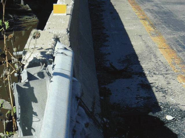
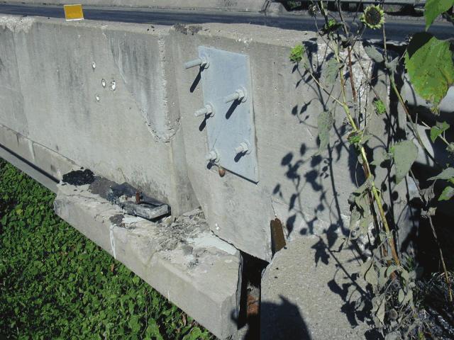
51
Pooled Fund Projects with Bogie or Full-Scale Crash Testing in Past Quarter
 MIDWEST POOLED FUND PROGRAM Progress Report - Fourth Quarter 2009 October 1 st to December 31 st Midwest Roadside Safety Facility Nebraska Transportation Center University of Nebraska-Lincoln December
Midwest States Pooled Fund Program Quarterly Progress Report First Quarter 2011 March 15, 2011
 Midwest States Pooled Fund Program Quarterly Progress Report First Quarter 2011 March 15, 2011 Project No.: RPFP-06-01 SPR-3(017) Supplemental #35 Project Title: Cost Effective Measures for Roadside Design
Pooled Fund Projects with Bogie or Full-Scale Crash Testing in Past Quarter
 MIDWEST POOLED FUND PROGRAM Progress Report - Third Quarter 2009 July 1 st to September 30 th Midwest Roadside Safety Facility Nebraska Transportation Center University of Nebraska-Lincoln September 30,
Sheikh et al. 1 PINNED-DOWN TEMPORARY CONCRETE BARRIER WITH TRANSITION SYSTEMS FOR LIMITED-SPACE WORK ZONE APPLICATIONS
 Sheikh et al. 1 PINNED-DOWN TEMPORARY CONCRETE BARRIER WITH TRANSITION SYSTEMS FOR LIMITED-SPACE WORK ZONE APPLICATIONS Nauman M. Sheikh Texas A&M Transportation Institute Texas A&M University System MS-3135
Ongoing MwRSF Research on Bridge Railings, Culvert Barriers, & Transitions
 Andrew Zickler, P.E. Complex Bridge Design and ABC Support Program Manager Virginia Department of Transportation AASHTO T-7 Technical Committee Spokane, Washington June 14, 2017 Ongoing MwRSF Research
Development of a Low-Cost, Energy-Absorbing, Bridge Rail
 Duplication for publication or sale is strictly prohibited without prior written permission of the Transportation Research Board Paper No. 11-2687 Development of a Low-Cost, Energy-Absorbing, Bridge Rail
Design and Testing of an Easy to Use Pinned-down Temporary Concrete Barrier with Limited Deflections
 12 th International LS-DYNA Users Conference Automotive(1) Design and Testing of an Easy to Use Pinned-down Temporary Concrete Barrier with Limited Deflections Nauman M. Sheikh and Roger P. Bligh Texas
Development of a Test Level 3 Transition Between Guardrail and Portable Concrete Barriers
 University of Nebraska - Lincoln DigitalCommons@University of Nebraska - Lincoln Civil Engineering Faculty Publications Civil Engineering 2017 Development of a Test Level 3 Transition Between Guardrail
DESIGN GUIDE. Advancing Safety Through Innovation. TCC-DG01 07/18/02 Page 1
 DESIGN GUIDE Advancing Safety Through Innovation Patents Pending Copyright 2002 BSI TCC-DG01 07/18/02 Page 1 TAU-II Crash Cushion DESIGN Table of Contents Preface 22 Introduction 2 Important Information..
TRAFFIC DIRECTION FOR RAIL LAP AS SHOWN (SEE NOTE 7) "SPLICE BOLT" WITH NUT MIDWEST GUARDRAIL SYSTEM (STANDARD AND REDUCED POST SPACING)
 SPLICE BOLT WITH NUT MIDWEST GUARDRAIL SYSTEM (STANDARD AND REDUCED POST SPACING)") TRAFFIC DIRECTION FOR RAIL LAP AS SHOWN GR-MGS1, 1A (SEE NOTE 7) NOTES: 1. 2. 3. 4. 5. 6. 236 6'-3" 6'-3" 3'-1 " 3'-1 " 3'-1 " 3'-1 " GR-MGS1 (6'-3" POST SPACING) SPLICE DETAIL W-BEAM RAIL SPLICE MID-SPAN
TRAFFIC DIRECTION FOR RAIL LAP AS SHOWN GR-MGS1, 1A (SEE NOTE 7) NOTES: 1. 2. 3. 4. 5. 6. 236 6'-3" 6'-3" 3'-1 " 3'-1 " 3'-1 " 3'-1 " GR-MGS1 (6'-3" POST SPACING) SPLICE DETAIL W-BEAM RAIL SPLICE MID-SPAN
Development of a Low-Cost, Energy-Absorbing, Bridge Rail
 Duplication for publication or sale is strictly prohibited without prior written permission of the Transportation Research Board Paper No. 11-2687 Development of a Low-Cost, Energy-Absorbing, Bridge Rail
Midwest States Pooled Fund Program Consulting Quarterly Summary
 Midwest States Pooled Fund Program Consulting Quarterly Summary Midwest Roadside Safety Facility 07-01-2018 to 10-01-2018 Guardrail Downstream Anchorage - TRP-03-279-13 Question State: FL Date: 07-18-2018
Design and Testing of Two Bridge Railings for Transverse Nail-Laminated Timber Deck Bridges
 Design and Testing of Two Bridge Railings for Transverse Nail-Laminated Timber Deck Bridges Mario Mongiardini, Scott K. Rosenbaugh, Ronald K. Faller, John D. Reid, Robert W. Bielenberg, and Dean L. Sicking
Performance of the Midwest Guardrail System with Rectangular Wood Posts
 Duplication for publication or sale is strictly prohibited without prior written permission of the Transportation Research Board Paper No. 14-2991 Performance of the Midwest Guardrail System with Rectangular
Anchoring and Stiffening Techniques for Portable Concrete Barriers
 University of Nebraska - Lincoln DigitalCommons@University of Nebraska - Lincoln Mechanical (and Materials) Engineering -- Dissertations, Theses, and Student Research Mechanical & Materials Engineering,
Non-Blocked, Midwest Guardrail System for Wire-Faced, MSE Walls
 Duplication for publication or sale is strictly prohibited without prior written permission of the Transportation Research Board Paper No. 11-2684 Non-Blocked, Midwest Guardrail System for Wire-Faced,
SUBJECT: Discussion Regarding Barriers & Barrier Transitions with Staff from the Midwest Roadside Safety Facility (Univ of Nebraska, Lincoln)
") Problem # 8 MnDOT Questions Regarding Bridge Barriers State Question and MwRSF Response: MnDOT had a conference call with MwRSF to discuss various questions regarding barriers on superelevations and cross
Problem # 8 MnDOT Questions Regarding Bridge Barriers State Question and MwRSF Response: MnDOT had a conference call with MwRSF to discuss various questions regarding barriers on superelevations and cross
GUIDERAILS INTRODUCTION DESIGN PURPOSE CHAPTER 12
 401 CHAPTER 12 GUIDERAILS INTRODUCTION The general intent of the highway engineer is to design a roadway in which the geometry creates a safe driving environment that does not require guiderail or median
Technical Memorandum: Road Safety Hardware Series. technical memorandum
 technical memorandum road safety hardware series Frequently Asked Questions - Barriers & Terminals TM-2000 October 2012 Purpose To provide a list of frequently asked questions with answers in regard to
ROADSIDE SAFETY BARRIER ELEMENTS Module 3
 2 ROADSIDE SAFETY BARRIER ELEMENTS Module 3 3 Roadside Design Options 4 Expected Crash Reduction of Relocation of Fixed Objects Source: NCHRP Report 500, Vol 6, Exhibit V-26 Purpose of Safety Barriers
Testing of the Retrofitted T102R Bridge Railing
 Testing of the Retrofitted T102R Bridge Railing IAC No. 88-3DDIA043, Project No. 409390 2004 Texas Transportation Institute Mr. Mark Bloschock Texas Transportation June Institute 2, 2004 TxDOT IAC No.
Design and Full-Scale Crash Testing of an Anchored Temporary Concrete Barrier and its Transition System for Use on Asphalt Pavement
 0 0 0 0 Design and Full-Scale Crash Testing of an Anchored Temporary Concrete Barrier and its Transition System for Use on Asphalt Pavement By Chiara Silvestri Dobrovolny *, Nauman M. Sheikh, Paul B. Fossier,
T-39 Thriebeam. Product Manual. NCHRP 350 Test Level 3 & 4 Compliant Barrier. Release 01/11
 T-39 Thriebeam NCHRP 350 Test Level 3 & 4 Compliant Barrier Product Manual T-39 is licensed to Ingal Civil Products by Trinity Industries Inc. of the U.S.A. www.ingalcivil.com.au T-39 Thriebeam NCHRP 350
MASH TL-4 Design and Evaluation of A Restorable Energy-Absorbing Concrete Barrier
 Duplication for publication or sale is strictly prohibited without prior written permission of the Transportation Research Board Paper No. -00 MASH TL- Design and Evaluation of A Restorable Energy-Absorbing
MASH TL-4 Design and Evaluation of A Restorable Energy-Absorbing Concrete Barrier
 University of Nebraska - Lincoln DigitalCommons@University of Nebraska - Lincoln Civil Engineering Faculty Publications Civil Engineering --0 MASH TL- Design and Evaluation of A Restorable Energy-Absorbing
MDS TL5 Minimum Deflection Systems
 MDS Minimum Deflection Systems Approvals FHWA NCHRP 350 MASH EN1317 H4 MDS BARRIERS Bridge & Road STEEL BARRIER SYSTEMS Page Page 1 1 V11 MDS BARRIERS Run-off-road crashes are one of the most common types
Development of MASH TL-3 Transition Between Guardrail and Portable Concrete Barriers
 InTrans Project Reports Institute for Transportation 6-26-2014 Development of MASH TL-3 Transition Between Guardrail and Portable Concrete Barriers David A. Gutierrez Midwest Roadside Safety Facility Robert
SMART CUSHION INNOVATIONS SCI100GM General Specifications
 SMART CUSHION INNOVATIONS SCI100GM General Specifications DESCRIPTION: The SCI100GM is a redirective, non-gating crash attenuator that consists of a base, supporting frames, a sled, side panels, a wire
MDS TL4 Minimum Deflection Systems
 MDS Approvals FHWA NCHRP 350 MASH-08 EN1317 H2 Bridge & Road STEEL BARRIER SYSTEMS Page 1 V11 Run-off-road crashes are one of the most common types of crashes in urban and highway environments. Installing
Development of Prefabricated Concrete Bridge Railings
 Development of Prefabricated Concrete Bridge Railings QUARTERLY PROGRESS REPORT Updated to include progress between April 1, 2017 to June 30, 2017 Period Submitted by Sri Sritharan, Terry Wipf, Ashley
Subject: ACTION: National Cooperative Highway Research Program (NCHRP) Report 350 Hardware Compliance Dates
 Report 350 Hardware Compliance Dates") Memorandum - FHWA Safety Program Page 1 of 2 Memorandum US Department of Transportation Federal Highway Administration Subject: ACTION: National Cooperative Highway Research Program (NCHRP) Report 350
Memorandum - FHWA Safety Program Page 1 of 2 Memorandum US Department of Transportation Federal Highway Administration Subject: ACTION: National Cooperative Highway Research Program (NCHRP) Report 350
Corrugated Guardrail and Box Beam Barriers
 HIGHWAY SAFETY CORPORATION PRODUCT SHOWCASE Highway Safety Corporation has been serving the highway construction industry for over 30 years. We are a major manufacturer and supplier of highway guardrail
RAILING DESIGN FOR NEW TRUSS BRIDGES. Texas Transportation Institute The Texas A&M University System College Station, Texas
 1. Report No. FHWA/TX-05/0-4419-4 4. Title and Subtitle RAILING DESIGN FOR NEW TRUSS BRIDGES 2. Government Accession No. 3. Recipient's Catalog No. Technical Report Documentation Page 5. Report Date October
QuadGuard System. General Specifications. CEN General Specifications
 QuadGuard System General Specifications CEN General Specifications QuadGuard System GENERAL SPECIFICATIONS I. GENERAL All QuadGuard Systems shall be designed and manufactured by Energy Absorption Systems,
Deck-Mounted Steel Post Barrier System
 University of Nebraska - Lincoln DigitalCommons@University of Nebraska - Lincoln Mechanical & Materials Engineering Faculty Publications Mechanical & Materials Engineering, Department of 2007 Deck-Mounted
Design and Implementation of the Manitoba Constrained-Width Tall Wall Barrier. Submitted by: Authors: Co-authors:
 Design and Implementation of the Manitoba Constrained-Width Tall Wall Barrier Submitted by: Authors: Harald P. Larsen, P.Eng. Roadside Safety Engineer Manitoba Infrastructure Traffic Engineering 420 215
Crash-Tested Bridge Railings for Timber Bridges
 In: Proceedings of 4th International bridge engineering conference; 1995 August 28 30; San Francisco, CA. Washington, DC: National Academy Press: 395-404; 1995. Vol. 2. Crash-Tested Bridge Railings for
Installation Manual. Orion. TL-3 Steel Barrier. VHD (v2)
") Installation Manual Orion TL-3 Steel Barrier VHD (v2) 300914 Table of Contents Orion Introduction.......... 3 Limitations & Warnings. 4 Before Installation..... 3 System Design & Design Considerations
Installation Manual Orion TL-3 Steel Barrier VHD (v2) 300914 Table of Contents Orion Introduction.......... 3 Limitations & Warnings. 4 Before Installation..... 3 System Design & Design Considerations
Barriers and highway accessory supports
 12.4 BARRIERS... 2 12.4.1 General... 2 12.4.2 Barrier joints... 3 12.4.3 Traffic barriers... 3 12.4.3.2 Test level... 3 12.4.3.2.1 General... 3 12.4.3.2.5 Test level for barriers on low volume roads...
Two Test Level 4 Bridge Railing and Transition Systems for Transverse Timber Deck Bridges
 University of Nebraska - Lincoln DigitalCommons@University of Nebraska - Lincoln Civil Engineering Faculty Publications Civil Engineering 2000 Two Test Level 4 Bridge Railing and Transition Systems for
Item 442 Metal for Structures
 Item 442 Metal for Structures 1. DESCRIPTION 2. MATERIALS Provide structural steel, high-strength bolts, forgings, steel castings, iron castings, wrought iron, steel pipe and tubing, aluminum castings
MASH 2016 Implementation- An AASHTO-FHWA Joint Plan
 MASH 2016 Implementation- An AASHTO-FHWA Joint Plan Presented by Chris Lindsey, TxDOT MASH 2016 Overview Background and Context MASH Implementation Agreement Availability of MASH Hardware Anticipated Costs
NOTES ON THE SPECIFICATION FOR ROAD SAFETY BARRIER SYSTEMS
 1. INTRODUCTION A road safety barrier is considered to be a hazard and should only be used when the consequences of hitting it are less than the hazard/object which it is shielding. The use of a road safety
Barriers, Parapets, and Railings
 Barriers, Parapets, and Railings Arielle Ehrlich State Bridge Design Engineer May 17, 2017 Bridge Office mndot.gov/bridge MnDOT Vocabulary Is it a barrier, a parapet or a railing? BARRIER. It is concrete
Product Specification ArmorGuard Barrier System
 TB 081030 Rev. 0 Page 1 of 6 Product Specification ArmorGuard Barrier System I. General The ArmorGuard Barrier System is a longitudinal barrier, as defined in the AASHTO Roadside Design Guide, which can
TRACC. Product Manual. Crash attenuation cushion. Release 10/14
 TRACC Crash attenuation cushion Product Manual Release 10/14 TRACC is licensed to Ingal Civil Products by Trinity Industries Inc. of the U.S.A. www.ingalcivil.com.au TRACC Crash attenuation cushion 1.0
TRACC. Crash Attenuation Cushion. Product Manual
 TRACC Crash Attenuation Cushion Product Manual Release 07/15 TRACC is licensed to Ingal Civil Products by Trinity Industries Inc. of the U.S.A. www.ingalcivil.com.au TRACC Crash Attenuation Cushion 1.0
TRACC. Crash Attenuation Cushion. Product Manual
 TRACC Crash Attenuation Cushion Product Manual Release 08/16 TRACC is licensed to Ingal Civil Products by Trinity Industries Inc. of the U.S.A. www.ingalcivil.com.au TRACC Crash Attenuation Cushion 1.0
APPLICATION OF A PRECAST CONCRETE BARRIER ADJACENT TO A STEEP ROADSIDE SLOPE
 1 2 3 4 5 6 7 8 9 10 11 12 13 14 15 16 17 18 19 20 21 22 23 24 25 26 27 28 29 30 31 32 33 34 35 36 37 38 39 APPLICATION OF A PRECAST CONCRETE BARRIER ADJACENT TO A STEEP ROADSIDE SLOPE Nauman M. Sheikh
Plans for Crash-Tested Bridge Railings for Longitudinal Wood Decks on Low-Volume Roads
 United States Department of Agriculture Forest Service Forest Products Laboratory General Technical Report FPL-GTR-107 Plans for Crash-Tested Bridge Railings for Longitudinal Wood Decks on Low-Volume Roads
Bridge Barriers Implementing the AS5100 Bridge Design Code Provisions
 Bridge Barriers Implementing the AS5100 Bridge Design Code Provisions By Vincenzo Colosimo, B.Eng, G.Dip.CE, G.Dip.ME, MICE. Bridge Loads Engineer VicRoads Design VicRoads SYNOPSIS Bridge Barriers have
LOCATION AND DESIGN DIVISION
 VIRGINIA DEPARTMENT OF TRANSPORTATION LOCATION AND DESIGN DIVISION INSTRUCTIONAL AND INFORMATIONAL MEMORANDUM GENERAL SUBJECT: ROADWAY SAFETY FEATURES SPECIFIC SUBJECT: NCHRP 350 TEST REQUIREMENTS LOCATION
Texas Transportation Institute The Texas A&M University System College Station, Texas
 1. Report No. FHWA/TX-04/0-1816-1 2. Government Accession No. 3. Recipient's Catalog No. Technical Report Documentation Page 4. Title and Subtitle EVALUATION OF ROADSIDE SAFETY DEVICES USING FINITE ELEMENT
Universal TAU-II Redirective, Non-Gating, Crash Cushion
 TB 010925 Rev. 2 Page 1 of 10 Product Specification Universal TAU-II Redirective, Non-Gating, Crash Cushion I. General The Universal TAU-II system is a Redirective, Non-Gating Crash Cushion in accordance
D D TYPE A1, A2 & B MICHIGAN DEPARTMENT OF TRANSPORTATION 5-40 CONNECTION. L4" x 4" x 3/8" Brace. C8 x 4.25 Strut. WT9 x 17.5.
 Sign length minus Adjust to avoid interference with sign legend A Deck fascia A 6" Equal Equal 6" Sign length (L) varies 6 to 12 PLAN 0 CONNECTION (DECK FASCIA) Angle connection assembly F Face of concrete
Chapter 4 Bridge Program Drawings
 Chapter 4 Bridge Program Drawings Section 4.10-Bridge Railing Introduction Steel bridge railing and concrete bridge barrier rail are installed along the edge of the bridge roadway to keep errant vehicles
LIST OF STANDARD DRAWINGS H2-9 - SERIES 9: Fencing, Guide Rails
 LIST OF STANDARD DRAWINGS H-9 - SERIES 9: Fencing, Guide Rails # Title Drawing 900.0 Chain Link Security Fence Chain Link Fence - For Roadway Installations 900.0 Installation of Barbed Wire - For Chain
Use of Energy Absorbing Breakaway Posts for W-Beam Guardrail in Frozen Soil Conditions
 Highway IDEA Program Use of Energy Absorbing Breakaway Posts for W-Beam Guardrail in Frozen Soil Conditions Final Report for Highway IDEA Project 149 Prepared by: King Mak and John Rhode Safety by Design
How Loads Are Distributed
 LOAD DISTRIBUTION 1 LOAD DISTRIBUTION This section illustrate how load will transmit from the deck to the stringers. Determining the fraction of load carried by a loaded member and the remainder distributed
MICHIGAN DEPARTMENT OF TRANSPORTATION SPECIAL PROVISION FOR LOW-TENSION CABLE BARRIER. OPR:CT 1 of 5 APPR:JAR:DBP: FHWA:APPR:
 MICHIGAN DEPARTMENT OF TRANSPORTATION SPECIAL PROVISION FOR LOW-TENSION CABLE BARRIER OPR:CT 1 of 5 APPR:JAR:DBP:09-07-11 FHWA:APPR:09-07-11 a. Description. This work consists of furnishing and installing
LOCATION AND DESIGN DIVISION
 VIRGINIA DEPARTMENT OF TRANSPORTATION LOCATION AND DESIGN DIVISION INSTRUCTIONAL AND INFORMATIONAL MEMORANDUM GENERAL SUBJECT: ROADWAY SAFETY FEATURES SPECIFIC SUBJECT: NCHRP 350 TEST REQUIREMENTS LOCATION
MICHIGAN DEPARTMENT OF TRANSPORTATION SPECIAL PROVISION FOR PREFABRICATED STEEL PEDESTRIAN BRIDGE, TYPE 2
 MICHIGAN DEPARTMENT OF TRANSPORTATION SPECIAL PROVISION FOR PREFABRICATED STEEL PEDESTRIAN BRIDGE, TYPE 2 OFS:MJF 1 of 10 APPR:JAB:POJ:09-29-18 FHWA:APPR:10-01-18 a. Description. This work consists of
SECTION VIBRATION CONTROLS FOR HVAC PIPING AND EQUIPMENT
 Page 230548-1 SECTION 230548 - PART 1 - GENERAL 1.1 RELATED DOCUMENTS A. Drawings and general provisions of the Contract, including General and Supplementary Conditions and Division 01 Specification Sections,
DEVELOPMENT OF A CRASWORTHY SUPPORT SYSTEM FOR LARGE TEMPORARY GUIDE SIGNS
 TRB 14-4791 DEVELOPMENT OF A CRASWORTHY SUPPORT SYSTEM FOR LARGE TEMPORARY GUIDE SIGNS by R. P. Bligh and D. R. Arrington Word Count: 5075 + (2 tables + 8 figures @ 250/ea) = 7575 Submission Date: August
New Jersey Turnpike Authority
 New Jersey Turnpike Authority DOCUMENT UPDATE REQUEST Forward to Assistant Chief Engineer, Design Initiator Russell Saputo, PE Submittal Date 6/21/16 Firm Stantec Consulting Services Inc. Telephone 201-587-9040
MICHIGAN DEPARTMENT OF TRANSPORTATION SPECIAL PROVISION FOR PREFABRICATED STEEL PEDESTRIAN BRIDGE, TYPE 2
 MICHIGAN DEPARTMENT OF TRANSPORTATION SPECIAL PROVISION FOR PREFABRICATED STEEL PEDESTRIAN BRIDGE, TYPE 2 OFS:MJF 1 of 10 APPR:JAB:POJ:07-07-17 FHWA:APPR:07-11-17 a. Description. This work consists of
SYNTHESIS OF THE PERFORMANCE OF PORTABLE CONCRETE BARRIER SYSTEMS
 Project No. 22-36 Copy No. SYNTHESIS OF THE PERFORMANCE OF PORTABLE CONCRETE BARRIER SYSTEMS PRELIMINARY DRAFT FINAL REPORT Prepared for National Cooperative Highway Research Program Transportation Research
SO-DEEP, 9/2015 (703) VA. Group I-DL. Group I-DL
 VA. Group I-DL. Group I-DL") LIMITED ACCESS HIGHWAY By Resolution of Commonwealth Transportation Board dated January 18, 2001 PROJECT MANAGER: SURVEYED BY, DATE: TIMOTHY HARTZELL, P.E. (703) 259-2749 (NOVA District) PRECISION MEASUREMENTS,
LIMITED ACCESS HIGHWAY By Resolution of Commonwealth Transportation Board dated January 18, 2001 PROJECT MANAGER: SURVEYED BY, DATE: TIMOTHY HARTZELL, P.E. (703) 259-2749 (NOVA District) PRECISION MEASUREMENTS,
Product Manual Release 05/17
 Temporary Safety Barrier (TL-2 MASH) Product Manual VHD (v3) www.valmonthighway.com Table of Contents 1.0 ArmorZone Introduction... 3 2.0 Before Installation... 3 3.0 Limitations & Warnings... 3 4.0 System
BRIDGE STANDARD PLANS AND SPECIAL DETAILS ADAM LANCASTER, P.E. FEB. 27, 2018
 BRIDGE STANDARD PLANS AND SPECIAL DETAILS ADAM LANCASTER, P.E. FEB. 27, 2018 NEW PUBLICATIONS 2016 LOUISIANA STANDARD SPECIFICATIONS FOR ROADS AND BRIDGES M.A.S.H. HIGHWAY GUARD RAIL STANDARD PLANS GUARD
Product Manual. QUEST CEN System. Redirective, Bidirectional Crash Cushion ENERGY ABSORPTION
 Redirective, Bidirectional Crash Cushion ENERGY ABSORPTION SYSTEMS, INC. A Quixote Company Saving Lives By Design Corporate Offices: 35 East Wacker Dr., 11th Floor Chicago, IL 60601-2076 Telephone: (312)
Practices for High-tension Cable Barriers. Presented to the AASHTO Subcommittee on Maintenance Providence, Rhode Island Wednesday, August 2, 2017
 Practices for High-tension Cable Barriers Presented to the AASHTO Subcommittee on Maintenance Providence, Rhode Island Wednesday, August 2, 2017 Synthesis Objectives To identify and report on the state
Field and Laboratory Performance of FRP Bridge Panels
 Field and Laboratory Performance of FRP Bridge s D. Stone, A. Nanni, & J. Myers University of Missouri Rolla, Rolla, Missouri, USA ABSTRACT: The objective of this research project is to examine the use
TEST REPORT. Rendered to: SENTINEL FENCE AND RAIL. For: 120 in by 42 in Fully-Welded Aluminum Guardrail Assembly with Intermediate Support Post
 TEST REPORT Rendered to: SENTINEL FENCE AND RAIL For: 120 in by 42 in Fully-Welded Aluminum Guardrail Assembly with Intermediate Support Post Report No: Report Date: 10/23/12 130 Derry Court York, PA 17406-8405
Concrete Barrier Temporary Precast
 Sheet a Sheet b Sheet c Sheet d SDD 14B7 Concrete Barrier Temporary Precast Version 12, June 11, 2010 Contact Person References Erik Emerson (608) 266-2842 Standard Spec 614 FDM 11-45-2 FDM 11-45-1 AASHTO
Midwest Roadside Safety Facility
 Bridge Pit 1504 1/2" 38214 244" 6198 1" 25 16 15 14 13 12 11 10 9 8 7 25 6 5 51 3/16" 1300 4 3 2 1 Impact 2270P 2455 5/16" 62365 1379 1/2" 35039 - Barrier nos. 5-13 Anchored Ground Line Note: (1) Test
B STEEL BEAM GUIDE RAIL - OPSS.PROV 721
 B721-2 - - OPSS.PROV 721 721-2.1 GENERAL Steel beam guide rail (SBGR) is a semi-rigid barrier system which restrains and redirects vehicles by a combination of beam bending (W-shaped steel section), tension,
SECTION VIBRATION CONTROLS FOR PLUMBING PIPING AND EQUIPMENT
 Page 220548-1 SECTION 220548 - PART 1 - GENERAL 1.1 RELATED DOCUMENTS A. Drawings and general provisions of the Contract, including General and Supplementary Conditions and Division 01 Specification Sections,
Installation and Repair Manual
 Trinity Attenuating Crash Cushion Installation and Repair Manual An NCHRP Report 350 Crash Cushion CSP Pacific Business Unit of Fletcher Concrete & Infrastructure Limited 306 Neilson Street Onehunga, Auckland
MICHIGAN DEPARTMENT OF TRANSPORTATION SPECIAL PROVISION FOR PREFABRICATED STEEL PEDESTRIAN BRIDGE, TYPE 1
 MICHIGAN DEPARTMENT OF TRANSPORTATION SPECIAL PROVISION FOR PREFABRICATED STEEL PEDESTRIAN BRIDGE, TYPE 1 OFS:MJF 1 of 10 APPR:JAB:POJ:09-29-18 FHWA:APPR:10-01-18 a. Description. This work consists of
MASH. When most people hear MASH, they think of the popular. Regulation CODES & STANDARDS
 CODES & STANDARDS MASH provides guidelines for crashtesting roadside barriers, including precast concrete barriers. It also recommends evaluation criteria to assess these test results. Photo courtesy of
SECTION 415 REINFORCING FOR CONCRETE
 SECTION 415 REINFORCING FOR CONCRETE Module 5 August 2018 Release 10, Module 5 1 Release 10, August 2018 5-1 415 1 Description Furnish and place steel and fiber reinforced polymer (FRP) reinforcing of
ITEM 555 CHAIN LINK FENCING
 ITEM 555 AFTER MARCH 1, 2012 CHAIN LINK FENCING 555.1 Description. This item shall govern for furnishing the quantities of chain link fencing and gates as shown on the plans, including all posts, bracing
Bridge Construction. Nick Haltvick North Region Bridge Construction Engineer May 17, Bridge Office mndot.gov/bridge/construction.
 Bridge Construction Nick Haltvick North Region Bridge Construction Engineer May 17, 2017 Bridge Office mndot.gov/bridge/construction.html Topics Bridge Construction Unit Special Provisions Update Bridge
B STEEL BEAM GUIDE RAIL - OPSS 552
 B552-2 - - OPSS 552 552-2.1 GENERAL Steel Beam Guide Rail (SBGR) is a semi-rigid barrier system which restrains and redirects vehicles by a combination of beam bending (W-shaped steel section), tension,
B STEEL BEAM GUIDE RAIL - OPSS 721
 B721-2 - - OPSS 721 721-2.1 GENERAL Steel Beam Guide Rail (SBGR) is a semi-rigid barrier system which restrains and redirects vehicles by a combination of beam bending (W-shaped steel section), tension,
B STEEL BEAM GUIDE RAIL - OPSS 721
 B721-2 - - OPSS 721 721-2.1 GENERAL Steel Beam Guide Rail (SBGR) is a semi-rigid barrier system which restrains and redirects vehicles by a combination of beam bending (W-shaped steel section), tension,
Qualified Products Policy #49 Page 1 of 8
 SOUTH CAROLINA DEPARTMENT OF TRANSPORTATION QUALIFIED PRODUCT POLICY 49 (QPP49) February 13, 2018 PERMANENT ROADSIDE SAFETY DEVICES & TRAFFIC BARRIER COMPONENTS MASH ERA 1. GENERAL: Qualified Product Policy
FEBRUARY 2019 LRFD BRIDGE DESIGN 5-1
 FEBRUARY 2019 LRFD BRIDGE DESIGN 5-1 5. CONCRETE STRUCTURES Reinforced and prestressed concrete are used extensively in bridge projects. In addition to general design guidance and information on detailing
Code Compliance Research Report CCRR-0118
 Code Compliance Research Report CCRR-0118 Issue Date: 12-15-2009 Revision Date: 04-30-2018 Renewal Date: 04-15-2019 DIVISION: 06 00 00 WOOD, PLASTIC, AND COMPOSITES Section: 06 63 00 - Plastic Railings
TRACC-Family System Manual
 Trinity Attenuating Crash Cushion TRACC-Family System Manual A Family of NCHRP Report 350 Crash Cushions Trinity Industries, Inc. 2525 Stemmons Freeway Dallas, Texas 75207 U.S. Calls: (800)-644-7976 International
Product Manual REACT 350 (36") (3 foot [915 mm] wide Systems) Reusable Energy Absorbing Crash Terminal
![Product Manual REACT 350 (36) (3 foot [915 mm] wide Systems) Reusable Energy Absorbing Crash Terminal](/thumbs/76/73919372.jpg "Product Manual REACT 350 (36) (3 foot [915 mm] wide Systems) Reusable Energy Absorbing Crash Terminal") (3 foot [915 mm] wide Systems) Reusable Energy Absorbing Crash Terminal Self-Restoring, Reusable Crash Cushions for Narrow Hazards ENERGY ABSORPTION SYSTEMS, INC. A Quixote Company Saving Lives By Design
(3 foot [915 mm] wide Systems) Reusable Energy Absorbing Crash Terminal Self-Restoring, Reusable Crash Cushions for Narrow Hazards ENERGY ABSORPTION SYSTEMS, INC. A Quixote Company Saving Lives By Design
Bridge Barrier Development Presentation to the MFLNRO April John Deenihan Ph.D., EIT Julien Henley M.A.Sc., P.Eng
 Bridge Barrier Development Presentation to the MFLNRO April 2014 John Deenihan Ph.D., EIT Julien Henley M.A.Sc., P.Eng Contents Introduction Contents Introduction Background Information / Synopsis Contents
PN Revision D January SoftStop. System. End Terminal. Product Manual
 PN 10007556 Revision D SoftStop End Terminal Product Manual System SoftStop System Tangent End Terminal The SoftStop System Tangent End Terminal ( SoftStop System ) has been tested to American Association
ITEM 442 METAL FOR STRUCTURES
 ITEM 442 METAL FOR STRUCTURES 442.1. Description. This Item shall govern for all structural steel, high strength bolts, forgings, steel castings, iron castings, wrought iron, bronze, steel pipe and tubing,
NORTHWESTERN UNIVERSITY PROJECT NAME JOB #
 SECTION 26 0529 - HANGERS AND SUPPORTS FOR ELECTRICAL SYSTEMS PART 1 - GENERAL 1.1 RELATED DOCUMENTS A. Drawings and general provisions of the Contract, including General and Supplementary Conditions and
RAMSHIELD. New Zealand Edition. Product & Installation Manual. MASH TL3 Compliant W-Beam Barrier. Ref: PM 023/0
 RAMSHIELD MASH TL3 Compliant W-Beam Barrier Product & Installation Manual New Zealand Edition Ref: PM 023/0 Table of Contents 1.0 Introduction... 5 2.0 Specifications... 5 3.0 How RAMSHIELD Works... 6
SECTION VIBRATION AND SEISMIC CONTROLS FOR HVAC PIPING AND EQUIPMENT
 SECTION 230548 - VIBRATION AND SEISMIC CONTROLS FOR HVAC PIPING AND EQUIPMENT PART 1 - GENERAL 1.1 RELATED DOCUMENTS A. Drawings and general provisions of the Contract, including General and Supplementary
Two Test Level 4 Bridge Railing and Transition Systems for Transverse Timber Deck Bridges
 334 Transportation Research Record 1696 Paper No. 5B0110 Two Test Level 4 Bridge Railing and Transition Systems for Transverse Timber Deck Bridges Ronald K. Faller, Michael A. Ritter, Barry T. Rosson,
Code Compliance Research Report CCRR-0238
 Code Compliance Research Report CCRR-0238 Issue Date: 11-09-2016 Revision Date: 11-29-2018 Renewal Date: 11-09-2019 DIVISION: 05 00 00 METALS Section: 05 52 00 Metal Railings CPG Building Products LLC