Crash-Tested Bridge Railings for Timber Bridges
|
|
|
- Antony Lester
- 6 years ago
- Views:
Transcription
1 In: Proceedings of 4th International bridge engineering conference; 1995 August 28 30; San Francisco, CA. Washington, DC: National Academy Press: ; Vol. 2. Crash-Tested Bridge Railings for Timber Bridges Michael A. Ritter, Forest Service, U.S. Department of Agriculture Ronald K. Faller, University of Nebraska-Lincoln Sheila R. Duwadi, Federal Highway Administration Bridge railing systems in the United States historically have been designed on the basis of static load criteria given in the AASHTO Standard Specifications for Highway Bridges. In the past decade, full-scale vehicle crash testing has been recognized as a more appropriate and reliable method of evaluating bridge railing acceptability. In 1989 AASHTO published Guide Specifications for Bridge Railings, which gives the recommendations and procedures to evaluate bridge railings by full-scale vehicle crash testing. In 1993 NCHRP published Report 350: Recommended Procedures for the Safety Performance Evaluation of Highway Features, which provides criteria for evaluating longitudinal barriers. From these specifications, a cooperative research program was initiated to develop and crash test several bridge railings for longitudinal wood decks. The research resulted in the successful development and testing of five bridge railing systems for longitudinally laminated wood bridge decks in accordance with the AASHTO Performance Level 1 and Performance Level 2 requirements and the Test Level 4 requirements of NCHRP Report 350. The primary purpose of a bridge railing is to safely contain vehicles that cross the bridge. To meet this objective, railings must be designed to withstand the force of vehicle impact. In designing railing systems for highway bridges, engineers traditionally have assumed that vehicle impact forces can be approximated by equivalent static loads that are applied to railing elements. Although railing loads are actually dynamic, the equivalent-static-load method has been used for many years as a simplified approach to standardized railing design. Currently, the AASHTO Standard Specifications for Highway Bridges (1) requires that rail posts be designed to resist an outward transverse static load of 44.5 kn (10,000 lb). A portion of this load is also applied to posts in the inward transverse, longitudinal, and vertical directions and to the rail elements. These requirements are identical for all bridges regardless of bridge geometry or traffic conditions. Thus, a railing for a single-lane bridge on a low-volume road must meet the same loading requirements as a railing for a bridge on a major highway. Despite the widespread use of design requirements based primarily on static load criteria, the need for more appropriate criteria for full-scale vehicle crash tests has long been recognized. The first U.S. guidelines for full-scale vehicle crash testing were published in 1962 (2) in a one-page document that provided basic guidelines for the test vehicle mass, approach speed, and impact angle and provided a degree of uniformity to the traffic barrier research in progress at the time. 395
2 396 FOURTH INTERNATIONAL BRIDGE ENGINEERING CONFERENCE Through subsequent use of this document, the need for additional comprehensive guidelines became apparent, and several reports were published during the 1970s through NCHRP. In 1981 NCHRP released NCHRP Report 230: Recommended Procedures for the Safety Performance Evaluation of Highway Appurtenances (3). This comprehensive report has been the primary source of crash testing criteria for more than a decade and continues to serve as the basis for current bridge railing testing requirements. Although crash test crireria have been available for many years, the requirement to implement crash testing as a means of evaluating bridge railings in the United States depended on the jurisdiction. Some states implemented extensive bridge railing crash testing programs, whereas others continued to use static load design exclusively. The first recognition of full-scale crash testing in a national bridge specification came in 1989, when AASHTO published the Guide Specifications for Bridge Railings (or AASHTO Guide Specifications) (4). This work presents recommendations for the development, testing, and use of crash-tested bridge railings and refers extensively to NCHRP 230 for crash testing procedures and requirements. A primary concept of the AASHTO Guide Specifications is that bridge railing performance needs differ greatly from site to site and that railing designs and costs should match site needs. Thus, recommended requirements for railing testing are based on three performance levels: Performance Level 1 (PL-1), PL-2, and PL-3. The PL-1 requirements represent the weakest system, and the PL-3 the strongest system. The relationship between the railing performance level and requirements for a specific bridge depend on a number of factors, such as the type of roadway, design speed, average daily traffic, and percentage of trucks in the traffic mix. The recently published NCHRP Report 350: Recommended Procedures for the Safety Performance Evaluation of Highway Features (5) provides for six test levels to evaluate longitudinal barriers: Test Level 1 (TL-1) through TL-6. Although this document does not include objective criteria for relating a test level to a specific roadway type, the lower test levels generally are intended for use on roadways with lower service levels and certain types of work zones, whereas the higher test levels are intended for use on higher-service-level roadways. Most highways on which wood bridges are installed will require railings that meet either the AASHTO PL-1 or PL-2 requirements or the NCHRP 350 TL-1 through TL-4 requirements. A railing that meets either PL-3, TL-5, or TL-6 requirements currently has a very limited application for wood bridges because of the high traffic volume and speeds associated with these levels. The AASHTO Guide Specifications are optional, and the use of static load design criteria is permitted. However, emphasis on the use of crash-tested railings for new federally funded projects has increased significantly the role of full-scale crash testing as a means of evaluating railing performance. It is anticipated that AASHTO will adopt the guide specifications in the future, making crash-tested railings mandatory for most bridges. FHWA has officially adopted NCHRP Report 350 as a replacement for NCHRP Report 230. At this time, it is unclear if AASHTO will adopt the Report 350 criteria into its guide specifications or retain the current criteria based on Report 230. As of August 1990, 25 bridge railings had been successfully crash tested in accordance with the requirements of the AASHTO Guide Specifications and approved for use on federal-aid projects by FHWA (6). Of these railings, 24 are for concrete bridge decks and 1 is for a wood deck. For wood bridges to compete with other bridges in the future, a range of crash-tested bridge raiiings for different wood bridge types will be required. Because of this need, national emphasis was placed on developing a limited number of crash-tested railings for wood bridges. OBJECTIVE AND SCOPE To meet the need for crashworthy railings for wood bridges, the Forest Products Laboratory, USDA Forest Service, in cooperation with the Midwest Roadside Safety Facility of the University of Nebraska at Lincoln, FHWA, and the wood products industry, initiated a program to develop crash-tested bridge railings for longitudinal wood decks. The program objectives were to develop five crashworthy railings: three to meet AASHTO PL-1, one to meet AASHTO PL-2, and one to meet NCHRP Report 350 TL-4. The scope of the project was limited to railings for longitudinal wood decks, 252 mm (10 in.) or greater in thickness, and constructed of glued-laminated (glulam) timber, spikelaminated lumber, or stress-laminated lumber. In each system, the lumber laminations are placed edgewise and oriented with the lumber length parallel to the direction of traffic. A brief description of each longitudinal deck bridge type is provided in Timber Bridges: Design, Construction, Inspection, and Maintenance (7). Longitudinal glulam timber decks are constructed of panels that consist of individual lumber laminations glued together with waterproof structural adhesives. The panels are 1.07 to 1.38 m (3.5 to 4.5 ft) wide and effectively function as a large, solid block of wood. To form the bridge deck, panels are placed side by side and interconnected by transverse distributor beams bolted to the deck underside at intervais of 2.4 m (8 ft) or less. These distributor beams are designed to transfer vertical
3 RITTER, FALLER, ET AL. 397 loads between adjacent panels. They are not designed to resist lateral loads. Spike-laminated decks are constructed of sawn lumber laminations 102 mm (4 in.) in nominal thickness. The individual laminations are interconnected with spikes that are typically 8 or 9.5 mm (5/16 or 3/8 in. ) in diameter and 356 to 406 mm (14 to 16 in.) long. The decks are commonly manufactured in panels that are 1.5 to 2.1 m (5 to 7 ft) wide and interconnected with transverse distributor beams in a manner similar to longitudinal glulam timber decks. Stress-laminated decks are constructed of sawn lumber laminations that are typically 51 to 102 mm (2 to 4 in.) in nominal thickness. The laminations are stressed together with high-strength steel bars that are placed in holes drilled through the center of the wide faces of the laminations. When tensioned, the bars create compression between the laminations, and the entire deck effectively acts as a solid, orthotropic wood plate. TEST REQUIREMENTs AND EVALUATION CRITERIA Test requirements and evaluation criteria for this project followed procedures defined in the AASHTO Guide Specifications (including applicable references to NCHRP Report 230) and the NCHRP Report 350 criteria. These procedures establish a uniform methodology for testing and evaluating railings so that the safety performance of different railing designs, tested and evaluated by different agencies, can be compared. It is impractical and impossible to test all railings for all possible vehicle and impact conditions. Therefore, the procedures specify a limited number of tests using severe vehicle impact conditions and a set of criteria against which test results may be evaluated. Test Requirements Vehicle impact requirements for railing crash resting depend on the railing performance or test level and are specified as requirements for vehicle type and weight, impact speed, and impact angle relative to the longitudinal railing axis. Testing for PL-1 requires two vehicle impact tests, and testing for PL-2 and TL-4 requires three vehicle impact tests. A summary of the requirements for PL-1, PL-2, and TL-4 is given in Table 1. In some cases, all tests for a given level may not be required if a railing with similar geometry and strength was tested previously and found to be satisfactory. In addition to vehicle impact requirements, the AASHTO Guide Specifications and the NCHRP Report 350 criteria also specify requirements for data acquisition and construction of the bridge railings. Requirements for data acquisition are referenced to Reports 230 and 350 and include specific data collection parameters and techniques that must be completed before, during, and after the crash test. Construction requirements specify that the bridge railing be designed, constructed, erected, and tested in a manner representative of actual installations. To assess properly the performance of most bridge railings, they must also be evaluated as a system in combination with the bridge superstructure for which it is intended. This is very important for railings for wood bridges, because the attachment of the railing to the bridge deck and the ability of the wood superstructure to resist applied railing loads may often be the controlling parameters. Evaluation Criteria Evaluation criteria for full-scale crash testing are based on three appraisal areas: structural adequacy, occupant risk, and vehicle trajectory after the collision. Criteria for structural adequacy are intended to evaluate the ability of the railing to contain, redirect, or permit controlled vehicle penetration in a predictable manner. Occupant risk evaluates the degree of hazard to occupants of the impacting vehicle. Vehicle trajectory after the collision is concerned with the path and final position of the impacting vehicle and the probable involvement of the impacting vehicle with other traffic. Note that these criteria address only the safety and dynamic performance of the railing and do not include service criteria such as aesthetics, economics, bridge damage, or postimpact maintenance requirements. The following evaluation criteria are summarized from the AASHTO Guide Specifications for PL-1 and PL-2 testing (similar evaluation criteria are provided in NCHRP Report 350): 1. The railing shall contain the vehicle; neither the vehicle nor its cargo shall penetrate or go over the installation. Controlled lateral deflection of the railing is acceptable. 2. Detached elements, fragments, or other debris from the railing shall not penetrate or show potential for penetrating the passenger compartment or present undue hazard to other traffic. 3. Integrity of the passenger compartment must be maintained with no intrusion and essentially no deformation. 4. The vehicle shall remain upright during and after collision. 5. The railing shall smoothly redirect the vehicle. A redirection is deemed smooth if the rear of the vehicle does not yaw more than 5 degrees away from the railing

4 398 FOURTH INTERNATIONAL BRIDGE ENGINEERING CONFERENCE from time of impact until the vehicle separates from the railing. 6. The smoothness of the vehicle-railing interaction is further assessed by the effective coefficient of friction µ, where µ = is good, µ = is fair, and µ > 0.36 is marginal. Requirements for computing µ are given in the AASHTO Guide Specifications. 7. The impact velocity of a hypothetical front-seat passenger against the vehicle interior, calculated from vehicle accelerations and 610-mm (2-ft) longitudinal and 305-mm (l-ft) lateral displacements, shall be less than 9.15 m/sec (30 ft/sec) in the longitudinal direction and 7.63 m/sec (25 ft/sec) in the lateral direction. In addition, the highest 10-msec average vehicie accelerations subsequent to the instant of hypothetical passenger impact should be less than 147 m/sec 2 (483 ft/sec 2 ) in the longitudinal and lateral directions. 8. Vehicle exit angle from the barrier shall not be more than 12 degrees. Within 30.5 m (100 ft) plus the length of the test vehicle from the point of initial impact with the railing, the railing side of the vehicle shall move no more than 6.1 m (20 fr) from the line of the traffic face of the railing. DEVELOPMENT PHASE Using a fundamental understanding of the performance characteristics of each deck type, development work was initiated to formulate a methodology for the railing tests. Because of economics and time, it was considered impractical to develop and test different railing systems for each longitudinal deck type. Instead, a more feasible approach was undertaken to develop several railing systems that could be adapted to each of the three longitudinal deck types, without modifications that would result in reduced performance. To accomplish this, it was determined that railing development and testing should use the weakest deck type. This decision was based on the premise that if successful tests could be completed on the weakest deck, the railing could be adapted to stronger decks without hurting performance. In assessing the potential resistance of each deck type to transverse railing impact forces, the strength of the wood and mechanical reinforcement was considered. Of primary concern was loading that could introduce tension perpendicular to grain stress in the wood deck. Of the three deck types, the stress-laminated deck was considered the strongest for transverse railing loads, because the high-strength steel bars are continuous across the deck width. Loads developed at vehicle impact can be effectively distributed across the deck by the bars, making the entire deck width effective in resisting the applied loads. The spike-laminated deck was considered to be of intermediate strength. If railing loads are applied transverse to the panel length, the loads are resisted by the spikes in withdrawal. Because of this, tension perpendicular to grain in the lumber laminations is not a concern; however, the spikes could be pulled from the deck, resulting in longitudinal separations between the laminations, and additional reinforcement would be required. The glulam timber deck was considered to be the weakest in resisting railing loads, because the glulam timber panels act as solid pieces of wood, and loads applied transverse to the panel length are most likely to introduce tension perpendicular to grain and failure in the upper panel section. Mechanical reinforcement was considered necessary for longitudinal glulam timber TABLE 1 Vehicle Impact Requirements for PL-1, PL-2, and TL-4 Bridge Railings


5


 cost of the raiiing system to the user, including material, fabrication, and construction; (d) ease of railing construction and maintenance; and (e)")

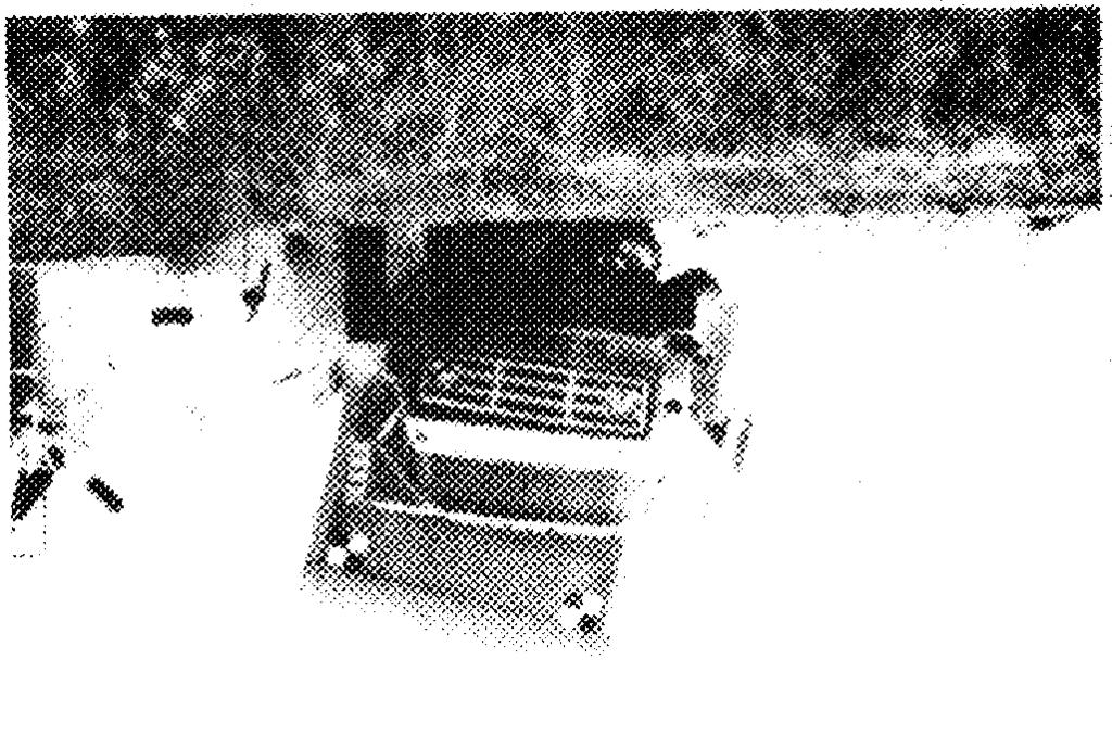
6 400 FOURTH INTERNATIONAL BRIDGE ENGINEERING CONFERENCE decks to resist railing loads without damage. Thus, the glulam timber deck was considered the weakest deck for transverse railing loads and was selected for fullscale crash testing. If bridge railings performed acceptably on the glulam timber system, it was rationalized that the railings could be adapted to the other longitudinal wood bridge decks with no reduction in railing performance. The primary emphasis of the railing design process was to develop railings that would meet the requirements for the AASHTO Guide Specifications and NCHRP Report 350. In addition, it was determined that consideration be given to (a) the extent of probable damage to the structure after vehicle impact and the difficulty and cost of required repairs; (b) adaptability of the railing to different wood deck types; (c) cost of the raiiing system to the user, including material, fabrication, and construction; (d) ease of railing construction and maintenance; and (e) aesthetics. The conclusion of the development phase involved the design of several railing systems and preparation of plans and specifications for testing. The selection and design of these final systems were based on a review of other railings that had been crash tested successfully, as well as those that are used on wood bridges but had not been crash tested. To the extent possible, feasible designs were evaluated using computer simulation models. Although several proven computer models were used, it was difficult to adapt the programs for wood components because the behavior and properties of the wood systems at ultimate loading were unknown. Data collected during the crash testing were used to refine input parameters and more accurately predict railing performance in subsequent tests. side by side to achieve the 2.4-m (8-ft) width, and transverse distributor beams were attached to the deck underside per AASHTO requirements (1). The test bridge was supported by concrete footings that were placed in excavations so that the top of the test bridge was level with the concrete surface at the site. TEST METHODOLOGY Testing of all bridge railings was completed at the Midwest Roadside Safety Facility in Lincoln, Nebraska. The site is located at an airport and was formerly a taxiway and parking area for military aircraft. It includes approximately 11 ha (27 acres) of concrete pavement and 1.6 ha (4 acres) of soil surface. To complete railing testing, a test bridge was constructed that measured approximately 2.4 m (8 ft) wide and 28.6 m (93.75 ft) long, in five simply supported spans measuring 5.72 m (18.75 ft) each. The deck was constructed of glulam timber panels 273 mm (10.75 in.) thick and 1.2 m (4 ft) wide. The glulam timber for the deck was Combination 2 Douglas fir given in the AASHTO Standard Specifications for Highway Bridges (1) and was treated with pentachlorophenol in heavy oil in accordance with American Wood Preservers Association (AWPA) Standard C14 (8). Two glulam timber panels were placed FIGURE 2 Bridge railings successfully crash tested to AASHTO PL-1 (photographs taken before testing).
7 FIGURE 3 Drawings of bridge railings successfully crash tested to AASHTO PL-1: top, glulam timber rail with curb; middle, glulam timber rail without curb; bottom, steel rail.

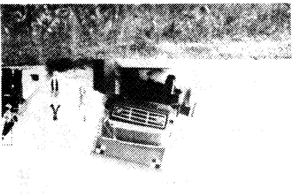
8 402 FOURTH INTERNATIONAL BRIDGE ENGINEERING CONFERENCE Vehicle propulsion and guidance were provided by steel cable configurations. For propulsion, a reverse cable tow with a 1:2 mechanical advantage was used. A cable was attached to the front of the vehicle, routed through a series of pulleys, and connected to a tow vehicle that traveled in a direction opposite to the test vehicle. The unoccupied test vehicle was then pulled by the tow vehicle and released from the tow cable approximately 9.2 m (30 ft) before impact. A vehicle guidance system developed by Hinch was used to steer the test vehicle (9). Using this system, the left front wheel hub is attached to a tensioned steel cable that maintains the vehicle s direction along a designated straight path. Approximately 9.2 m (30 ft) from impact, the guidance connection is sheared off and the vehicle separates from the guidance cable. A crash-test sequence for an kg (18,000-lb) vehicle is shown in Figure 1. Data acquisition parameters and techniques for the crash testing program were based on requirements of the AASHTO Guide Specifications and NCHRP Report 350 and followed three testing phases: pretest, test, and posttest. In the pretest phase, the as-built bridge railing and vehicle were documented using photography and drawings that indicated the applicable configuration, dimensions, and vehicle weight. During the test phase, data on the vehicle impact speed, impact angle, trajectory, and accelerations were collected primarily through the use of high-speed motion picture photography and accelerometers mounted on the vehicle. In the posttest phase, the condition of the railing, bridge superstructure, and vehicle were documented using photography and standardized damage assessment methods, including the traffic accident data scale (10) and vehicle damage index (11). Additional instrumentation was placed, FIGURE 4 Steel thrie beam bridge railing successfully crash tested to AASHTO PL-2 (photograph taken before testing).


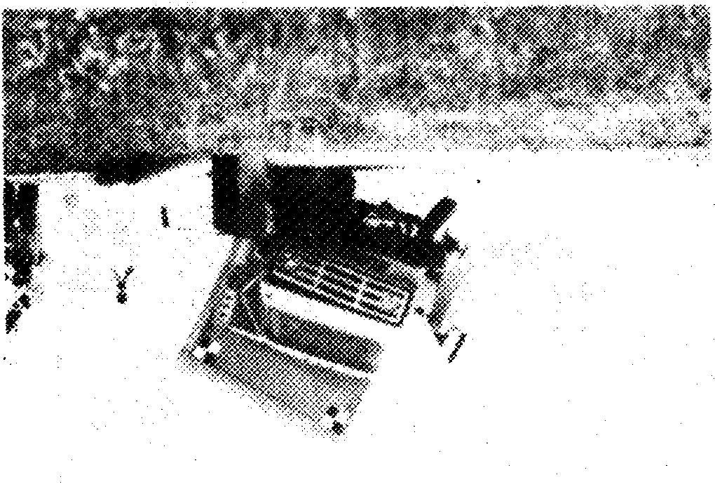
9 RITTER, FALLER, ET AL. 403 FIGURE 5 Glulam timber bridge railing successfully crash tested taken before testing). to NCHRP Report 350 TL-4 (photograph on some railings to assess vehicle impact forces transmitted to the bridge railing and superstructure. RESULTS AND DISCUSSION As a result of the development and testing program, five bridge railings were successfully developed and tested for longitudinal wood decks. Three of these railings were tested at PL-1, one was tested at PL-2, and one was tested at TL-4. Each railing was tested on the glulam timber deck and is adaptable to the spike-laminated and stress-laminated decks. All designs used posts spaced 1.9 m (6.25 ft) on center and high-strength steel bars through a portion of the bridge deck to act as reinforcement in distributing railing loads without dam- age to the bridge. Glulam timber for the rail members was Combination 2 Douglas fir as given in the AASHTO Standard Specifications for Highway Bridges (1), treated with pentachlorophenol in heavy oil to AWPA C14 requirements (8). Sawn lumber for posts, curbs, scuppers, and spacer blocks was No. 1 Douglas fir (1), treated with creosote to AWPA C14 requirements (8). A detailed discussion of the testing and results for each railing system is beyond the scope of this paper but is presented in detail in previous publications (12,13). Overall, no damage to the test bridge was evident from any of the vehicle impact tests. For the railing systems with glulam timber rails, damage to the railing was primarily gouging and scraping resulting from the vehicle impact. All glulam timber railing remained


10 404 FOURTH INTERNATIONAL BRIDGE ENGINEERING CONFERENCE intact and serviceable after the tests, and replacement of the railing was not considered necessary. For the steel rhrie beam railings, there was permanent deformation in the rail and post in the vicinity of the impact location. This would necessitate replacement of specific railing and post members, but damage was relatively minor considering the severity of the impact. A brief description of each railing design follows. PL-1 Railings The three tested PL-1 railings included a glulam timber railing with curb, a glulam timber railing without curb, and a steel thrie beam railing. Photographs and drawings of the PL-1 railings are shown in Figures 2 and 3, respectively. The glulam timber railing with curb consisted of a singie glulam timber railing mounted on a sawn lumber post. The post was connected with a single bolt to a lumber curb that was supported by scupper blocks. The curb and scupper blocks were connected to the bridge deck with bolts and timber connectors. The glulam timber railing without curb consisted of a single glulam timber railing mounted on a sawn lumber post. The lower portion of the post was placed in a steel box that was attached to the bridge deck with high strength steel bars. The steel railing consisted of a 10-gauge steel thrie beam railing mounted to a steel, wide flange post. The lower end of the post was bolted to a steel plate that was connected to the bridge deck with high-strength steel bars. CONCLUDING REMARKS This program clearly demonstrates that crashworth y railing systems are feasible for longitudinal wood decks. Even at high-impact conditions required by AASHTO PL-2 and NCHRP Report 350 TL-4, the railing systems performed well with no significant damage to the bridge superstructure. The development of crashworthy railing systems has overcome a significant barrier to the use of longitudinal deck wood bridges. REFERENCES PL-2 Railing The one PL-2 railing included a steel thrie beam railing, as shown in Figure 4. The steel railing was a modified version of that tested at PL-1. Minor changes in the railing geometry and the addition of a steel channel section above the rail element were necessary to resist the increased loads at PL-2. TL-4 Railing The one TL-4 railing included a glulam timber railing with curb, as shown in Figure 5. The railing consisted of a single glulam timber railing mounted on a sawn lumber post and was a modification of the curb system tested at PL-1. Because of the greater loads at TL-4, railing and post sizes were increased, as were bolts and timber connectors attaching the curb and scupper to the bridge deck. on recycled paper
Crash-Tested Bridge Railings for Timber Bridges
 Crash-Tested Bridge Railings for Timber Bridges Michael A. Ritter, Forest Service, U.S. Department of Agriculture Ronald K. Faller, University of Nebraska-Lincoln Sheila R. Duwadi, Federal Highway Administration
Two Test Level 4 Bridge Railing and Transition Systems for Transverse Timber Deck Bridges
 University of Nebraska - Lincoln DigitalCommons@University of Nebraska - Lincoln Civil Engineering Faculty Publications Civil Engineering 2000 Two Test Level 4 Bridge Railing and Transition Systems for
Two Test Level 4 Bridge Railing and Transition Systems for Transverse Timber Deck Bridges
 334 Transportation Research Record 1696 Paper No. 5B0110 Two Test Level 4 Bridge Railing and Transition Systems for Transverse Timber Deck Bridges Ronald K. Faller, Michael A. Ritter, Barry T. Rosson,
Universal TAU-II Redirective, Non-Gating, Crash Cushion
 TB 010925 Rev. 2 Page 1 of 10 Product Specification Universal TAU-II Redirective, Non-Gating, Crash Cushion I. General The Universal TAU-II system is a Redirective, Non-Gating Crash Cushion in accordance
Design and Testing of Two Bridge Railings for Transverse Nail-Laminated Timber Deck Bridges
 Design and Testing of Two Bridge Railings for Transverse Nail-Laminated Timber Deck Bridges Mario Mongiardini, Scott K. Rosenbaugh, Ronald K. Faller, John D. Reid, Robert W. Bielenberg, and Dean L. Sicking
Product Specification ArmorGuard Barrier System
 TB 081030 Rev. 0 Page 1 of 6 Product Specification ArmorGuard Barrier System I. General The ArmorGuard Barrier System is a longitudinal barrier, as defined in the AASHTO Roadside Design Guide, which can
Dynamic Evaluation of Timber Bridges
 Dynamic Evaluation of Timber Bridges Terry J. Wipf, Civil & Construction Engineering, Iowa State University Michael A. Ritter, Forest Products USDA Forest Service Douglas L. Wood, Civil & Construction
Designing Timber Highway Bridge Superstructures Using AASHTO LRFD Specifications
 Designing Timber Highway Bridge Superstructures Using AASHTO LRFD Specifications Authors: James P. Wacker, Forest Products Laboratory, U.S. Forest Service, Madison, WI, jwacker@fs.fed.us James S. Groenier,
How Loads Are Distributed
 LOAD DISTRIBUTION 1 LOAD DISTRIBUTION This section illustrate how load will transmit from the deck to the stringers. Determining the fraction of load carried by a loaded member and the remainder distributed
Bridge Barrier Development Presentation to the MFLNRO April John Deenihan Ph.D., EIT Julien Henley M.A.Sc., P.Eng
 Bridge Barrier Development Presentation to the MFLNRO April 2014 John Deenihan Ph.D., EIT Julien Henley M.A.Sc., P.Eng Contents Introduction Contents Introduction Background Information / Synopsis Contents
QuadGuard System. General Specifications. CEN General Specifications
 QuadGuard System General Specifications CEN General Specifications QuadGuard System GENERAL SPECIFICATIONS I. GENERAL All QuadGuard Systems shall be designed and manufactured by Energy Absorption Systems,
ROADSIDE SAFETY BARRIER ELEMENTS Module 3
 2 ROADSIDE SAFETY BARRIER ELEMENTS Module 3 3 Roadside Design Options 4 Expected Crash Reduction of Relocation of Fixed Objects Source: NCHRP Report 500, Vol 6, Exhibit V-26 Purpose of Safety Barriers
RAIL SYSTEMS FOR TIMBER DECKS
 RAIL SYSTEMS FOR TIMBER DECKS 10.1 INTRODUCTION Railing is provided on bridges for the protection of vehicles and pedestrians that use the structure. It is normally placed along bridge sides to prevent
J.P. Wacker, M. ASCE. Abstract
 In: American Society of Civil Engineers: Proceedings of the ASCE Structures Congress, May 2004, Nashville, Tennessee. 2004 Field Performance of Stress-Laminated Highway Bridges Constructed with Glued Laminated
Design and Testing of an Easy to Use Pinned-down Temporary Concrete Barrier with Limited Deflections
 12 th International LS-DYNA Users Conference Automotive(1) Design and Testing of an Easy to Use Pinned-down Temporary Concrete Barrier with Limited Deflections Nauman M. Sheikh and Roger P. Bligh Texas
Design and Implementation of the Manitoba Constrained-Width Tall Wall Barrier. Submitted by: Authors: Co-authors:
 Design and Implementation of the Manitoba Constrained-Width Tall Wall Barrier Submitted by: Authors: Harald P. Larsen, P.Eng. Roadside Safety Engineer Manitoba Infrastructure Traffic Engineering 420 215
Barriers and highway accessory supports
 12.4 BARRIERS... 2 12.4.1 General... 2 12.4.2 Barrier joints... 3 12.4.3 Traffic barriers... 3 12.4.3.2 Test level... 3 12.4.3.2.1 General... 3 12.4.3.2.5 Test level for barriers on low volume roads...
MISCELLANEOUS WOOD STRUCTURES
 CHAPTER 10 MISCELLANEOUS WOOD STRUCTURES Michael A. Ritter, P.E. Keith F. Faherty, Ph.D., P.E. 10.1 WOOD BRIDGES 10.1.1 Introduction Wood was probably the first material used by humans to construct a bridge.
Applications of Wood Materials for Innovative Bridge Systems
 In: Suprenant, Bruce S., ed. Serviceability and durability of construction materials: Proceedings of 1st materials engineering congress; 1990 August 13-15; Denver, CO. New York: American Society of Civil
Design, Construction, and Evaluation of Timber Bridge Constructed of Cottonwood Lumber
 ln: Proceedings of 4th International bridge engineering conference; 1995 August 28 30; San Francisco, CA. Washington, DC: National Academy Press: 358-370; 1995. Vol. 2. Design, Construction, and Evaluation
Field Load Testing of the First Vehicular Timber Bridge in Korea
 Field Load Testing of the First Vehicular Timber Bridge in Korea Ji-Woon Yi Ph.D. Student Department of Civil & Environmental Engineering Seoul National University Seoul, Korea jwyi@sel.snu.ac.kr Wonsuk
Stress-Laminated / Steel T-Beam Bridge System
 Stress-Laminated / Steel T-Beam Bridge System David A. Apple and Clinton Woodward, New Mexico State University Abstract The stress-laminated timber bridge deck has been successfully used for short span
Bridge Barriers Implementing the AS5100 Bridge Design Code Provisions
 Bridge Barriers Implementing the AS5100 Bridge Design Code Provisions By Vincenzo Colosimo, B.Eng, G.Dip.CE, G.Dip.ME, MICE. Bridge Loads Engineer VicRoads Design VicRoads SYNOPSIS Bridge Barriers have
DESIGN GUIDE. Advancing Safety Through Innovation. TCC-DG01 07/18/02 Page 1
 DESIGN GUIDE Advancing Safety Through Innovation Patents Pending Copyright 2002 BSI TCC-DG01 07/18/02 Page 1 TAU-II Crash Cushion DESIGN Table of Contents Preface 22 Introduction 2 Important Information..
Performance Level 1 Bridge Railings for Timber Decks
 TRANSPORTATION RESEARCH RECORD' 1419 21 Performance Level 1 Bridge Railings for Timber Decks RONALD K. FALLER, MICHAEL A. RITTER, }AMES C. HOLLOWAY, BRIAN G. PFEIFER, AND BARRY T. ROSSON Historically,
Texas Transportation Institute The Texas A&M University System College Station, Texas
 1. Report No. FHWA/TX-04/9-8132-2 2. Government Accession No. 3. Recipient's Catalog No. 4. Title and Subtitle EVALUATION OF THE FDOT VARIANT OF THE MODIFIED KANSAS CORRAL BRIDGE RAILING 5. Report Date
GUIDERAILS INTRODUCTION DESIGN PURPOSE CHAPTER 12
 401 CHAPTER 12 GUIDERAILS INTRODUCTION The general intent of the highway engineer is to design a roadway in which the geometry creates a safe driving environment that does not require guiderail or median
Plans for Crash-Tested Bridge Railings for Longitudinal Wood Decks on Low-Volume Roads
 United States Department of Agriculture Forest Service Forest Products Laboratory General Technical Report FPL-GTR-107 Plans for Crash-Tested Bridge Railings for Longitudinal Wood Decks on Low-Volume Roads
The Federal Highway Administration Timber Bridge Program
 The Federal Highway Administration Timber Bridge Program Sheila Rimal Duwadi and Robert C. Wood, Federal Highway Administration Abstract The Federal Highway Administration (FHWA), as directed by the Intermodal
February 9, In Reply Refer To: HSST/CC-114
 Mr. Geoff Maus Chief Design Engineer TrafFix Devices, Inc. 160 Avenida La Pata San Clemente, California 92673 Dear Mr. Maus: February 9, 2011 1200 New Jersey Ave., SE Washington, D.C. 20590 In Reply Refer
STATE OF THE ART REPORT: GLULAM TIMBER BRIDGE DESIGN IN THE U.S.
 In: Proceedings of 27th meeting of International council for building research studies and documentation, working commission W18 Timber structures; 1994 July 7-8; Sydney, Australia. Germany: Universitat
Design and analysis of an aluminum F-shape bridge railing
 1 2 Design and analysis of an aluminum F-shape bridge railing 3 4 M H Ray and E Oldani Worcester Polytechnic Institute, 100 Institute Road, Worcester, MA 01609 doi:10.1533/ijcr.2004.0295 5 6 7 8 9 10 11
Reliability Analysis of Plank Decks for Bridges
 Reliability Analysis of Plank Decks for Bridges Andrzej S. Nowak and Vijay Saraf, Department of Civil and Environmental Engineering, University of Michigan, Ann Arbor Abstract The major parameters which
Chapter 4 Bridge Program Drawings
 Chapter 4 Bridge Program Drawings Section 4.10-Bridge Railing Introduction Steel bridge railing and concrete bridge barrier rail are installed along the edge of the bridge roadway to keep errant vehicles
Subject: ACTION: National Cooperative Highway Research Program (NCHRP) Report 350 Hardware Compliance Dates
 Report 350 Hardware Compliance Dates") Memorandum - FHWA Safety Program Page 1 of 2 Memorandum US Department of Transportation Federal Highway Administration Subject: ACTION: National Cooperative Highway Research Program (NCHRP) Report 350
Memorandum - FHWA Safety Program Page 1 of 2 Memorandum US Department of Transportation Federal Highway Administration Subject: ACTION: National Cooperative Highway Research Program (NCHRP) Report 350
Development of a Test Level 3 Transition Between Guardrail and Portable Concrete Barriers
 University of Nebraska - Lincoln DigitalCommons@University of Nebraska - Lincoln Civil Engineering Faculty Publications Civil Engineering 2017 Development of a Test Level 3 Transition Between Guardrail
Sheikh et al. 1 PINNED-DOWN TEMPORARY CONCRETE BARRIER WITH TRANSITION SYSTEMS FOR LIMITED-SPACE WORK ZONE APPLICATIONS
 Sheikh et al. 1 PINNED-DOWN TEMPORARY CONCRETE BARRIER WITH TRANSITION SYSTEMS FOR LIMITED-SPACE WORK ZONE APPLICATIONS Nauman M. Sheikh Texas A&M Transportation Institute Texas A&M University System MS-3135
DEVELOPMENT AND TESTING OF PORTABLE GLULAM TIMBER BRIDGE SYSTEMS
 DEVELOPMENT AND TESTING OF PORTABLE GLULAM TIMBER BRIDGE SYSTEMS Steven E. Taylor Associate Professor Biosystems Engineering Department Auburn University, AL 36849-5417 334-844-3534 (Voice) 334-844-3530
Deck-Mounted Steel Post Barrier System
 University of Nebraska - Lincoln DigitalCommons@University of Nebraska - Lincoln Mechanical & Materials Engineering Faculty Publications Mechanical & Materials Engineering, Department of 2007 Deck-Mounted
Field Performance of Timber Bridges
 United States Department of Agriculture Forest Service Forest Products Laboratory Timber Bridge Information Resource Center Research Paper FPL RP 556 In cooperation with the United States Department of
Phase III Guideline for Barrier Selection and Design
 R E P O R T P R O P O S A L AUGUST 2011 BRITISH COLUMBIA Ministry of Forests, Lands and Natural Resource Operations Phase III Guideline for Barrier Selection and Design REPORT Table of Contents SECTION
DEKALB COUNTY, INDIANA TREATED TIMBER STRUCTURES ANNUAL BID SPECIFICATIONS BID SHEET. 1) Treated Timber Bridge Planking...$ /MFBM
 Treated Timber Bridge Planking...$ /MFBM") Name of Bidder: Address of Bidder: BID SHEET 1) Treated Timber Bridge Planking...$ /MFBM 2) Treated Timber Box Culverts...$ /MFBM 3) Treated Timber Laminated Deck Panels...$ /MFBM 4) Copper Naphthenate
Name of Bidder: Address of Bidder: BID SHEET 1) Treated Timber Bridge Planking...$ /MFBM 2) Treated Timber Box Culverts...$ /MFBM 3) Treated Timber Laminated Deck Panels...$ /MFBM 4) Copper Naphthenate
The Use of Eastern Cottonwood for Stress Laminated Sawn Lumber Bridges in Iowa. Paula Hilbrich Lee Michael Ritter
 The Use of Eastern Cottonwood for Stress Laminated Sawn Lumber Bridges in Iowa Paula Hilbrich Lee Michael Ritter Historical Reference 1988 Timber Bridge Initiative Legislation passed by Congress. Objective:
GUARDRAIL WARRANTS FOR LOW VOLUME ROADS
 74 GUARDRAIL WARRANTS FOR LOW VOLUME ROADS Louis B. Stephens, P.E. INTRODUCTION Low volume roads present many challenges to highway engineers and public administrators. Although, by definition, these facilities
Portable T-Section Glulam Timber Bridge Modules: Modeling and Performance
 DRAFT FINAL REPORT Portable T-Section Glulam Timber Bridge Modules: Modeling and Performance Steven E. Taylor, Associate Professor Department of Biosystems Engineering, Auburn University Paul A. Morgan,
Field and Laboratory Performance of FRP Bridge Panels
 Field and Laboratory Performance of FRP Bridge s D. Stone, A. Nanni, & J. Myers University of Missouri Rolla, Rolla, Missouri, USA ABSTRACT: The objective of this research project is to examine the use
Dead Loads. Load Resistance ηγ i Q i ΦR n. Design Criteria. EGCE 406 Bridge Design III. Loads on Bridge Summary of Concepts.
 Design Criteria We want the load effects to be less than the resistance EGCE 406 Bridge Design III. Loads on Bridge Summary of Concepts This Section Load Resistance ηγ i Q i ΦR n Load Multiplier Nominal
FATIGUE OF DIAPHRAGM-GIRDER CONNECTIONS
 Executive Summary RP 930-307 FATIGUE OF DIAPHRAGM-GIRDER CONNECTIONS Sponsored by The Alabama Department of Transportation Montgomery, Alabama Presented by J. Michael Stallings Thomas E. Cousins J. W.
At the spring meeting of 1993 the AASHTO Subcommittee
 Impact of Load and Resistance Factor Design Specifications on Short- to Medium-Span Steel Bridges Dennis R. Mertz, University of Delaware John M. Kulicki, Modjeski and Masters, Inc. In 1993, AASHTO adopted
Field Performance of Timber Bridges
 United States Department of Agriculture Forest Service Forest Products Laboratory National Wood in Transportation Information Center Research Paper FPL RP 597 In cooperation with the United States Department
Anchoring and Stiffening Techniques for Portable Concrete Barriers
 University of Nebraska - Lincoln DigitalCommons@University of Nebraska - Lincoln Mechanical (and Materials) Engineering -- Dissertations, Theses, and Student Research Mechanical & Materials Engineering,
April 2, 2018 PARTIES INTERESTED IN CROSS LAMINATED TIMBER PANELS USED AS COMPONENTS IN FLOOR AND ROOF DECKS
 April 2, 2018 TO: PARTIES INTERESTED IN CROSS LAMINATED TIMBER PANELS USED AS COMPONENTS IN FLOOR AND ROOF DECKS SUBJECT: Proposed Revisions to the ICC-ES Acceptance Criteria for Cross-laminated Timber
Engineering Design Process: Structural Design
 Engineering Design Process: Structural Design Introduction Structural engineering is the design of structural elements and their connections that work together to support loads and maintain stability within
Installation Manual. Orion. TL-3 Steel Barrier. VHD (v2)
") Installation Manual Orion TL-3 Steel Barrier VHD (v2) 300914 Table of Contents Orion Introduction.......... 3 Limitations & Warnings. 4 Before Installation..... 3 System Design & Design Considerations
Installation Manual Orion TL-3 Steel Barrier VHD (v2) 300914 Table of Contents Orion Introduction.......... 3 Limitations & Warnings. 4 Before Installation..... 3 System Design & Design Considerations
Comparative Analysis of Design Codes for Timber Bridges in Canada, the United States, and Europe
 Comparative Analysis of Design Codes for Timber Bridges in Canada, the United States, and Europe James P. Wacker and James (Scott) Groenier The United States recently completed its transition from the
Testing of the Retrofitted T102R Bridge Railing
 Testing of the Retrofitted T102R Bridge Railing IAC No. 88-3DDIA043, Project No. 409390 2004 Texas Transportation Institute Mr. Mark Bloschock Texas Transportation June Institute 2, 2004 TxDOT IAC No.
EFFECT OF COLD TEMPERATURES ON STRESS-LAMINATED TIMBER BRIDGE DECKS
 42 EFFECT OF COLD TEMPERATURES ON STRESS-LAMINATED TIMBER BRIDGE DECKS James A. Kainz and Michael A. Ritter This paper summarizes Forest Products Laboratory research on stress-laminated timber bridge decks
Texas Transportation Institute The Texas A&M University System College Station, Texas
 1. Report No. FHWA/TX-05/9-8132-3 4. Title and Subtitle TESTING AND EVALUATION OF THE FLORIDA F SHAPE RIDGE RAILWITH REDUCED DECK THICKNESS 2. Government Accession No. 3. Recipient's Catalog No. 5. Report
Simplified Analytical Model for a Queen-Post Covered Timber Bridge
 Simplified Analytical Model for a Queen-Post Covered Timber Bridge Summary By F. Fanous D. Rammer T. Wipf Professor Research Engineer Professor and Chair Iowa State University Forest Product Laboratory
Building bridges - from Scandinavia to the USA
 Andrew Lawrence Associate Arup Technology & Research London, United Kingdom Building bridges - from Scandinavia to the USA Bauarten von Skandinavien bis Nordamerika Sistemi di costruzione dalla Scandinavia
WOOD I-JOIST AWARENESS GUIDE
 WOOD I-JOIST AWARENESS GUIDE American Wood Council Flange Web Flange American Forest & Paper Association WOOD I-JOIST AWARENESS GUIDE The American Wood Council is part of the wood products group of the
The Design and Installation of the Hopland Casino Bridge
 The Design and Installation of the Hopland Casino Bridge Paul C. Gilham, P.E. Chief Engineer Western Wood Structures, Inc. Tualatin, Oregon USA 1. Summary The Hopland Band of Pomo Indians constructed a
Technical Memorandum: Road Safety Hardware Series. technical memorandum
 technical memorandum road safety hardware series Frequently Asked Questions - Barriers & Terminals TM-2000 October 2012 Purpose To provide a list of frequently asked questions with answers in regard to
Changes to the following sections of Tollway Structure Design Manual shall apply:
 DESIGN BULLETIN No. 18-02 Changes to the following sections of Tollway Structure Design Manual shall apply: 1. Section 7.1.4 Note 25. (Revise to) Horizontal design loads for retaining walls with moment
Chapter 13 Bridge Load Rating
 Chapter 13 Bridge Load Rating Contents 13.1 General 13.1-1 13.1.1 WSDOT Rating (LRFR) 13.1-2 13.1.2 NBI Rating (LFR) 13.1-8 13.2 Special Rating Criteria 13.2-1 13.2.1 Dead Loads 13.2-1 13.2.2 Live Load
Euro NCAP Mobile Progressive Deformable Barrier Face Specification Draft Version December 2017 TB 022
 Technical Bulletin Euro NCAP Mobile Progressive Deformable Barrier Face Specification Draft Version 1.0.1 TB 022 Title Euro NCAP MPDB Specification Version v1.0.1 Draft Document Number TB022 Author J Ellway
Design and Full-Scale Crash Testing of an Anchored Temporary Concrete Barrier and its Transition System for Use on Asphalt Pavement
 0 0 0 0 Design and Full-Scale Crash Testing of an Anchored Temporary Concrete Barrier and its Transition System for Use on Asphalt Pavement By Chiara Silvestri Dobrovolny *, Nauman M. Sheikh, Paul B. Fossier,
Development of a Low-Cost, Energy-Absorbing, Bridge Rail
 Duplication for publication or sale is strictly prohibited without prior written permission of the Transportation Research Board Paper No. 11-2687 Development of a Low-Cost, Energy-Absorbing, Bridge Rail
Cross Frame Design for Curved and Skewed Bridges
 Cross Frame Design for Curved and Skewed Bridges Using AASHTO LRFD, 8 th Edition Travis Butz, PE To View Presentation on Your Mobile Device: www.burgessniple.com/event/2018/otec Cross frames in the 8 th
NOTES ON THE SPECIFICATION FOR ROAD SAFETY BARRIER SYSTEMS
 1. INTRODUCTION A road safety barrier is considered to be a hazard and should only be used when the consequences of hitting it are less than the hazard/object which it is shielding. The use of a road safety
EGCE 406: Bridge Design
 EGCE 406: Bridge Design Design of Slab for Praveen Chompreda Mahidol University First Semester, 2006 Bridge Superstructure Outline Components of bridge Superstructure Types Materials Design of RC Deck
National Transportation Safety Board Washington, D.C
 E PLUR IBUS UNUM NATIONAL TRA SAFE T Y N S PORTATION B OAR D National Transportation Safety Board Washington, D.C. 20594 Safety Recommendation Date: January 15, 2008 In reply refer to: H-08-1 The Honorable
Chapter 1. General Design Information. Section 1.03 Loads and Load Factors. Introduction. Load Modifying Factors
 Chapter 1 Bridge Design Manual General Design Information Section 1.03 Loads and Load Factors Introduction This section defines the loads and load factors to be used in structural analysis and design.
AS THE EFFECT ON BRIDGE BARRIERS
 ABSTRACT AS5100.2 2017 THE EFFECT ON BRIDGE BARRIERS David Coe, Senior Principal, Pitt & Sherry The revision to AS5100 in 2017 resulted in significant changes to the design loading and impact heights for
Ongoing MwRSF Research on Bridge Railings, Culvert Barriers, & Transitions
 Andrew Zickler, P.E. Complex Bridge Design and ABC Support Program Manager Virginia Department of Transportation AASHTO T-7 Technical Committee Spokane, Washington June 14, 2017 Ongoing MwRSF Research
FINAL STRUCTURAL ASSESSMENT COASTAL TRAIL BRIDGES ASSESSMENT. Anchorage, Alaska
 FINAL STRUCTURAL ASSESSMENT COASTAL TRAIL BRIDGES ASSESSMENT Anchorage, Alaska August 2014 Prepared for: Municipality of Anchorage Project Management and Engineering P.O. Box 196650 Anchorage, Alaska 99519-6650
Behavior of Stress-Laminated Parallel-Chord Timber Bridge Decks
 United States Department of Agriculture Forest Service Forest Products Laboratory Research Paper FPL-RP-511 Behavior of Stress-Laminated Parallel-Chord Timber Bridge Decks Experimental and Analytical Studies
Louisiana Transportation Research Center
 Louisiana Transportation Research Center Final Report 547 Performance and Analysis of Concrete Bridge Railing using Conventional and Composite Reinforcement Materials by Walid R. Alaywan, Ph.D., P.E. LTRC
LOADS AND FORCES ON TIMBER BRIDGES
 LOADS AND FORCES ON TIMBER BRIDGES 6.1 INTRODUCTION A bridge must be designed to safely resist all loads and forces that may reasonably occur during its life. These loads include not only the weight of
PIER PROTECTION (VEHICLE COLLISION) September 13, 2018
 September 13, 2018") PIER PROTECTION (VEHICLE COLLISION) September 13, 2018 Table of contents 1 Introduction 4-7 2 Investigation 8-19 3 Redirect vs. Structural Resistance 20-21 4 Redirect 22-33 5 Structural Resistance 34-39
PIER PROTECTION (VEHICLE COLLISION) September 13, 2018 Table of contents 1 Introduction 4-7 2 Investigation 8-19 3 Redirect vs. Structural Resistance 20-21 4 Redirect 22-33 5 Structural Resistance 34-39
FINAL REPORT EFFECT OF GIRDER SPACING ON BRIDGE DECK RESPONSE. James G. Buckler Graduate Research Assistant
 FINAL REPORT EFFECT OF GIRDER SPACING ON BRIDGE DECK RESPONSE James G. Buckler Graduate Research Assistant Furman W. Barton Faculty Research Scientist Jose P. Gomez Senior Research Scientist Peter J. Massarelli
Investigation of Negative Moment Reinforcing in Bridge Decks
 Tech Transfer Summaries Institute for Transportation 9-2015 Investigation of Negative Moment Reinforcing in Bridge Decks Brent Phares Institute for Transportation, bphares@iastate.edu Sameera Jayathilaka
Modjeski and Masters, Inc. Consulting Engineers 04/18/06 St. Croix River Bridge 3D Analysis Report Introduction
 Introduction This memo presents a summary of a three dimensional (3D) analysis of the Organic concept for the proposed St. Croix River bridge project. The Organic concept has several attributes that are
SUBJECT: Discussion Regarding Barriers & Barrier Transitions with Staff from the Midwest Roadside Safety Facility (Univ of Nebraska, Lincoln)
") Problem # 8 MnDOT Questions Regarding Bridge Barriers State Question and MwRSF Response: MnDOT had a conference call with MwRSF to discuss various questions regarding barriers on superelevations and cross
Problem # 8 MnDOT Questions Regarding Bridge Barriers State Question and MwRSF Response: MnDOT had a conference call with MwRSF to discuss various questions regarding barriers on superelevations and cross
Structural Behavior and Design of Barrier- Overhang Connection in Concrete Bridge Superstructures Using AASHTO LRFD Method
 University of New Haven Digital Commons @ New Haven Civil Engineering Faculty Publications Civil Engineering 1 Structural Behavior and Design of Barrier- Overhang Connection in Concrete Bridge Superstructures
PERFORMANCE EVALUATION OF THE GUARDRAIL TO CONCRETE BARRIER TRANSITION UPDATE TO NCHRP 350 TEST NO WITH 28" C.G.
 PERFORMANCE EVALUATION OF THE GUARDRAIL TO CONCRETE BARRIER TRANSITION UPDATE TO NCHRP 350 TEST NO. 3-21 WITH 28" C.G. HEIGHT (2214T-1) Submitted by Karla A. Polivka, M.S.M.E., E.I.T. Research Associate
Class Topics & Objectives
 EGCE 406: Bridge Design Design of Slab for Bridge Deck Praveen Chompreda, Ph.D. Mahidol University First Semester, 2010 Class Topics & Objectives Topics Objective Bridge Superstructures Students can identify
Non-Blocked, Midwest Guardrail System for Wire-Faced, MSE Walls
 Duplication for publication or sale is strictly prohibited without prior written permission of the Transportation Research Board Paper No. 11-2684 Non-Blocked, Midwest Guardrail System for Wire-Faced,
Barriers, Parapets, and Railings
 Barriers, Parapets, and Railings Arielle Ehrlich State Bridge Design Engineer May 17, 2017 Bridge Office mndot.gov/bridge MnDOT Vocabulary Is it a barrier, a parapet or a railing? BARRIER. It is concrete
Experimental Evaluation of Guard Rail Systems for Bridges
 Experimental Evaluation of Guard Rail Systems for Bridges For Ministry of Forests and Range, Engineering Branch, Field Operations Division (MoFR) Vancouver - July 15, 2010 By C. Villiard, M. Khorasani,
Development of Prefabricated Concrete Bridge Railings
 Development of Prefabricated Concrete Bridge Railings QUARTERLY PROGRESS REPORT Updated to include progress between April 1, 2017 to June 30, 2017 Period Submitted by Sri Sritharan, Terry Wipf, Ashley
CONSTRUCTION SPECIFICATION FOR STEEL BEAM GUIDE RAIL AND CABLE GUIDE RAIL
 ONTARIO PROVINCIAL STANDARD SPECIFICATION METRIC OPSS.MUNI 721 NOVEMBER 2014 CONSTRUCTION SPECIFICATION FOR STEEL BEAM GUIDE RAIL AND CABLE GUIDE RAIL TABLE OF CONTENTS 721.01 SCOPE 721.02 REFERENCES 721.03
T-39 Thriebeam. Product Manual. NCHRP 350 Test Level 3 & 4 Compliant Barrier. Release 01/11
 T-39 Thriebeam NCHRP 350 Test Level 3 & 4 Compliant Barrier Product Manual T-39 is licensed to Ingal Civil Products by Trinity Industries Inc. of the U.S.A. www.ingalcivil.com.au T-39 Thriebeam NCHRP 350
ANALYTICAL MODELING OF GLUED LAMINATED GIRDER BRIDGES USING ANSYS
 ANALYTICAL MODELING OF GLUED LAMINATED GIRDER BRIDGES USING ANSYS Anil Kurian, Department of Civil and Construction Engineering Iowa State University ABSTRACT This paper aims at developing a finite element
Fatigue Design Criteria of MPC Wood Trusses for Bridge Applications
 Fatigue Design Criteria of MPC Wood Trusses for Bridge Applications Habib J. Dagher, Brent West and Vincent Caccese, University of Maine Ron Wolfe and Michael Ritter, Forest Products Laboratory, USDA Forest
3.5 What guidance is there?
 3.5 What guidance is there? 3.5.1 General A number of specifications and codes of practice for the use of road plates were identified during the literature review. The main points from these documents
Field Performance of Timber Bridges
 United States Department of Agriculture Forest Service Forest Products Laboratory National Wood in Transportation Information Center Research Paper FPL RP 566 Field Performance of Timber Bridges 15. Pueblo
Work Zone Positive Protection Toolbox
 Work Zone Positive Protection Toolbox This booklet serves as a toolbox to describe various types of positive protection devices currently in use and provides guidance on where and how each is typically
THE NEW AASHTO MANUAL FOR BRIDGE EVALUATION 2008
 LOAD & RESISTANCE FACTOR RATING OF HIGHWAY BRIDGES FHWA LRFR Seminar SESSION 5 THE NEW AASHTO MANUAL FOR BRIDGE EVALUATION 2008 Bala Sivakumar, P.E. HNTB Corp. 2005 AASHTO BRIDGE MEETING AASHTO Adopted
Corrugated Guardrail and Box Beam Barriers
 HIGHWAY SAFETY CORPORATION PRODUCT SHOWCASE Highway Safety Corporation has been serving the highway construction industry for over 30 years. We are a major manufacturer and supplier of highway guardrail