Bridge Barrier Development Presentation to the MFLNRO April John Deenihan Ph.D., EIT Julien Henley M.A.Sc., P.Eng
|
|
|
- Buck McDaniel
- 5 years ago
- Views:
Transcription


1 Bridge Barrier Development Presentation to the MFLNRO April 2014 John Deenihan Ph.D., EIT Julien Henley M.A.Sc., P.Eng
2 Contents Introduction
3 Contents Introduction Background Information / Synopsis
4 Contents Introduction Background Information / Synopsis Literature Review
5 Contents Introduction Background Information / Synopsis Literature Review Barrier Selection Guidelines
6 Contents Introduction Background Information / Synopsis Literature Review Barrier Selection Guidelines Existing Barrier Configurations
7 Contents Introduction Background Information / Synopsis Literature Review Barrier Selection Guidelines Existing Barrier Configurations CL-2 Barrier Development
8 Contents Introduction Background Information / Synopsis Literature Review Barrier Selection Guidelines Existing Barrier Configurations CL-2 Barrier Development CL-3 Barrier Development
9 Contents Introduction Background Information / Synopsis Literature Review Barrier Selection Guidelines Existing Barrier Configurations CL-2 Barrier Development CL-3 Barrier Development CL-3 Barrier for Slab Bridges
10 Introduction CAN/CSA-S6-06 Primary reference for industrial road bridge design in Canada. It does NOT directly relate to industrial road bridge design.
11 Introduction CAN/CSA-S6-06 Primary reference for industrial road bridge design in Canada. It does NOT directly relate to industrial road bridge design. All jurisdictions in North America require the use of crash tested barriers, with the exception of the BC Ministry of Forests, Lands and Natural Resource Operations (Ministry) and the Ministry of Natural Resources in Ontario. None specifically address the containment of industrial traffic.
12 Introduction CAN/CSA-S6-06 Primary reference for industrial road bridge design in Canada. It does NOT directly relate to industrial road bridge design. All jurisdictions in North America require the use of crash tested barriers, with the exception of the BC Ministry of Forests, Lands and Natural Resource Operations (Ministry) and the Ministry of Natural Resources in Ontario. None specifically address the containment of industrial traffic. The Ministry has a long history of successful utilization of timber curbs/guide rails.
13 Background Information / Synopsis The Ministry retained Associated Engineering (AE) in 2010 to assist in the development of reasonable bridge barrier design guidelines, including specified design parameters, for Forest Service Road Bridge Guide Rails.
14 Background Information / Synopsis The Ministry retained Associated Engineering (AE) in 2010 to assist in the development of reasonable bridge barrier design guidelines, including specified design parameters, for Forest Service Road Bridge Guide Rails. The University of British Columbia (UBC) under the direction of Prof. Sigi Stiemer conducted an experimental investigation into the static lateral load capacity of barrier configurations currently adopted by the Ministry.
15 Background Information / Synopsis The Ministry retained Associated Engineering (AE) in 2010 to assist in the development of reasonable bridge barrier design guidelines, including specified design parameters, for Forest Service Road Bridge Guide Rails. The University of British Columbia (UBC) under the direction of Prof. Sigi Stiemer conducted an experimental investigation into the static lateral load capacity of barrier configurations currently adopted by the Ministry. Based on recommendations from reports presented to the Ministry, and UBC s findings, AE were retained to develop standard bridge barrier drawings to assist the Ministry s implementation of our previous recommendations.
16 Literature Review We conducted an extensive literature review of current practices for the design of bridge barriers on low volume roads and forestry road bridges in North America.
17 Literature Review We conducted an extensive literature review of current practices for the design of bridge barriers on low volume roads and forestry road bridges in North America. The review focused on: 1. Current regulatory requirements and guidelines 2. Research related to barrier design and selection 3. Standard bridge barriers currently used by various regulatory authorities.
18 Literature Review We conducted an extensive literature review of current practices for the design of bridge barriers on low volume roads and forestry road bridges in North America. The review focused on: 1. Current regulatory requirements and guidelines 2. Research related to barrier design and selection 3. Standard bridge barriers currently used by various regulatory authorities. The following presents a summary of the key findings of the literature review.
19 Literature Review - CAN/CSA-S6-06 The Canadian Highway Bridge Design Code (CHBDC) CAN/CSA-S6-06 offers a prescriptive approach to railing design.
20 Literature Review - CAN/CSA-S6-06 The Canadian Highway Bridge Design Code (CHBDC) CAN/CSA-S6-06 offers a prescriptive approach to railing design. Three Performance Levels (PL-1, PL-2 & PL-3)
21 Literature Review - CAN/CSA-S6-06 The Canadian Highway Bridge Design Code (CHBDC) CAN/CSA-S6-06 offers a prescriptive approach to railing design. Three Performance Levels (PL-1, PL-2 & PL-3) CHBDC bases the selection of a performance level on a Barrier Exposure Index that accounts for: o Highway Type o Highway Curvature o Highway Grade o Superstructure Height (crossing land or water) o Annual Average Daily Traffic (AADT)
22 Literature Review - CAN/CSA-S6-06 The Canadian Highway Bridge Design Code (CHBDC) CAN/CSA-S6-06 offers a prescriptive approach to railing design. Three Performance Levels (PL-1, PL-2 & PL-3) CHBDC bases the selection of a performance level on a Barrier Exposure Index Based on the Barrier Exposure Index, Design Speed, Percentage of Truck Traffic and Barrier Clearance, CHBDC provides guidance on the selection of the most appropriate Performance Level.
23 Literature Review - CAN/CSA-S6-06 The Canadian Highway Bridge Design Code (CHBDC) CAN/CSA-S6-06 offers a prescriptive approach to railing design. Three Performance Levels (PL-1, PL-2 & PL-3) CHBDC bases the selection of a performance level on a Barrier Exposure Index Based on the Barrier Exposure Index, Design Speed, Percentage of Truck Traffic and Barrier Clearance, CHBDC provides guidance on the selection of the most appropriate Performance Level. Barriers need to be crash tested.
24 Literature Review - CAN/CSA-S6-06 The Canadian Highway Bridge Design Code (CHBDC) CAN/CSA-S6-06 offers a prescriptive approach to railing design. Three Performance Levels (PL-1, PL-2 & PL-3) CHBDC bases the selection of a performance level on a Barrier Exposure Index Based on the Barrier Exposure Index, Design Speed, Percentage of Truck Traffic and Barrier Clearance, CHBDC provides guidance on the selection of the most appropriate Performance Level. Barriers need to be crash tested. CHBDC provides design forces to enable designers to design the barrier-to-deck connection, without the need for crash testing.
25 Literature Review - CAN/CSA-S6-06 The Canadian Highway Bridge Design Code (CHBDC) CAN/CSA-S6-06 offers a prescriptive approach to railing design. Three Performance Levels (PL-1, PL-2 & PL-3) CHBDC bases the selection of a performance level on a Barrier Exposure Index Based on the Barrier Exposure Index, Design Speed, Percentage of Truck Traffic and Barrier Clearance, CHBDC provides guidance on the selection of the most appropriate Performance Level. Barriers need to be crash tested. CHBDC provides design forces to enable designers to design the barrier-to-deck connection, without the need for crash testing. Several Provincial Ministry's require the use of Standard Barrier Details
26 Literature Review - CAN/CSA-S6-06 Supplement No. 3 (3013) to S6-06, incorporated a new Low Volume Road Bridge Barrier (TL-1) for roads with: Widths 8.6 m Deck height above ground or water surface 5.0 m max AADT = 100 for max design speed of 80 km/h max AADT = 400 for max design speed of 50 km/h
27 Literature Review - BC MoTI The British Columbia Ministry of Transport and Infrastructure (MoTI) provides some guidance on the use of bridge barriers for low volume roads in the Low Volume Road Bridge Design Guidelines.
28 Literature Review - BC MoTI The British Columbia Ministry of Transport and Infrastructure (MoTI) provides some guidance on the use of bridge barriers for low volume roads in the Low Volume Road Bridge Design Guidelines. The MoTI accepts crash tested Test Level 1 (TL-1) barriers when: ADT 50. Deck height above the channel bottom 4.0 m. Operating speed 50 km/hr. Bridge width < 8.5 m.
29 Literature Review - Ontario The Ontario Ministry of Transport (MTO) offers some guidance on the use of barriers with performance levels less than that mandated by CHBDC, for low-volume, low-speed, and low-hazard bridges.
30 Literature Review - Ontario The Ontario Ministry of Transport (MTO) offers some guidance on the use of barriers with performance levels less than that mandated by CHBDC, for low-volume, low-speed, and low-hazard bridges. The MTO defines two levels of barriers, LVPL1 and LVPL2 for consideration on low volume roads, based on AADT, Deck Height, Design Speed and Bridge Width. LVPL 2 (TL-1) LVPL 1 (sub TL-1)
31 Literature Review - Ontario The Ontario Ministry of Transport (MTO) offers some guidance on the use of barriers with performance levels less than that mandated by CHBDC, for low-volume, low-speed, and low-hazard bridges. The MTO defines two levels of barriers, LVPL1 and LVPL2 for consideration on low volume roads, based on AADT, Deck Height, Design Speed and Bridge Width. MTO provides standard drawings for approved barrier configurations.
32 Literature Review - Ontario The Ontario Ministry of Transport (MTO) offers some guidance on the use of barriers with performance levels less than that mandated by CHBDC, for low-volume, low-speed, and low-hazard bridges. The MTO defines two levels of barriers, LVPL1 and LVPL2 for consideration on low volume roads, based on AADT, Deck Height, Design Speed and Bridge Width. MTO provides standard drawings for approved barrier configurations. The Ontario Ministry of Natural Resources (MNR) provides guidance on the use of bridge barriers for forestry and resource roads in Crown Land Bridge Management Guidelines.
33 Literature Review - Ontario The Ontario Ministry of Transport (MTO) offers some guidance on the use of barriers with performance levels less than that mandated by CHBDC, for low-volume, low-speed, and low-hazard bridges. The MTO defines two levels of barriers, LVPL1 and LVPL2 for consideration on low volume roads, based on AADT, Deck Height, Design Speed and Bridge Width. MTO provides standard drawings for approved barrier configurations. The Ontario Ministry of Natural Resources (MNR) provides guidance on the use of bridge barriers for forestry and resource roads in Crown Land Bridge Management Guidelines. The document states that curbs and railings need not be designed to withstand live loads specified in the Bridge Code. They are intended to mark the edge of the bridge deck and need not be designed to deflect an impacting vehicle.
34 Literature Review - Ontario The Ontario Ministry of Transport (MTO) offers some guidance on the use of barriers with performance levels less than that mandated by CHBDC, for low-volume, low-speed, and low-hazard bridges. The MTO defines two levels of barriers, LVPL1 and LVPL2 for consideration on low volume roads, based on AADT, Deck Height, Design Speed and Bridge Width. MTO provides standard drawings for approved barrier configurations. The Ontario Ministry of Natural Resources (MNR) provides guidance on the use of bridge barriers for forestry and resource roads in Crown Land Bridge Management Guidelines. The document states that curbs and railings need not be designed to withstand live loads specified in the Bridge Code. They are intended to mark the edge of the bridge deck and need not be designed to deflect an impacting vehicle. MNR provides standard drawings for approved barrier configurations.
35 Literature Review - MFLNRO (pre-research & development outlined in this presentation). The Ministry's Forest Service Bridge Design and Construction Manual and Interim MFR Bridge Design Guidelines provides limited guidance on barrier design for forestry roads.
36 Literature Review - MFLNRO (pre-research & development outlined in this presentation). The Ministry's Forest Service Bridge Design and Construction Manual and Interim MFR Bridge Design Guidelines provides limited guidance on barrier design for forestry roads. Bridge rails must conform to one of three standard design options o Timber Curbs o W-Beam o HSS Beam HSS BEAM W-Beam Timber Curb
37 Literature Review - MFLNRO (pre-research & development outlined in this presentation). The Ministry's Forest Service Bridge Design and Construction Manual and Interim MFR Bridge Design Guidelines provides limited guidance on barrier design for forestry roads. Bridge rails must conform to one of three standard design options o Timber Curbs o W-Beam o HSS Beam Bridge design must conform to CHBDC, modified to suit forestry bridges.
38 Literature Review - MFLNRO (pre-research & development outlined in this presentation). The Ministry's Forest Service Bridge Design and Construction Manual and Interim MFR Bridge Design Guidelines provides limited guidance on barrier design for forestry roads. Bridge rails must conform to one of three standard design options o Timber Curbs o W-Beam o HSS Beam Bridge design must conform to CHBDC, modified to suit forestry bridges. They appear to be performing successfully, however, they have not been crash-tested, nor do they appear to meet the design and selection requirements of either the CHDBC or AASHTO LRFD.
39 Literature Review AASHTO LRFD AASHTO forms the basis for most North American (bridge barrier) design codes and judristrictional guidelines.
40 Literature Review AASHTO LRFD AASHTO forms the basis for most North American (bridge barrier) design codes and judristrictional guidelines. Six barrier Test Levels, (TL-1 through TL-6). AASHTO CHBDC MFLNRO - - CL-1 TL-1 TL-1 CL-2 TL-2 PL-1 CL-3 TL-3 - PL-2 TL-4 - TL-5 PL-3 - TL-6 - -
41 Literature Review AASHTO LRFD AASHTO forms the basis for most North American (bridge barrier) design codes and judristrictional guidelines. Six barrier Test Levels, (TL-1 through TL-6). Introduced a methodology that requires Owners develop warrants for bridge sites and chose a railing system that satisfies the concerns of the warrants as completely as possible and practical.
42 Literature Review AASHTO LRFD AASHTO forms the basis for most North American (bridge barrier) design codes and judristrictional guidelines. Six barrier Test Levels, (TL-1 through TL-6). Introduced a methodology that requires Owners develop warrants for bridge sites and chose a railing system that satisfies the concerns of the warrants as completely as possible and practical. AASHTO LRFD states that all barriers and barrier-deck connections must be crash-tested, it provides design loads and loading configurations to facilitate the preliminary design of test specimen barriers.
43 Literature Review AASHTO Guidelines for Geometric Design of Very Low-Volume Local Roads (ADT 400) The guidelines introduce a basis for a risk management approach to barrier design.
44 Literature Review US Forest Service Transportation Structures Handbook 2011 (yet to be implemented) Permits the use of curb-only barrier systems for bridges at low-hazard sites that experience low volumes of low speed traffic (provided delineators provide sufficient advance waning for the bridge).
45 Literature Review US Forest Service Transportation Structures Handbook 2011 (yet to be implemented) Permits the use of curb-only barrier systems for bridges at low-hazard sites that experience low volumes of low speed traffic (provided delineators provide sufficient advance waning for the bridge). Requires that barrier systems meet the desired test levels by crash testing or can be geometrically and structurally evaluated as equal to a crash-tested system (numerical evaluation).
46 Literature Review US Forest Service Transportation Structures Handbook 2011 (yet to be implemented) Permits the use of curb-only barrier systems for bridges at low-hazard sites that experience low volumes of low speed traffic (provided delineators provide sufficient advance waning for the bridge). Requires that barrier systems meet the desired test levels by crash testing or can be geometrically and structurally evaluated as equal to a crash-tested system (numerical evaluation). Test Levels reflect the requirements specified in AASHTO LFRD.
47 Literature Review US Forest Service Transportation Structures Handbook 2011 (yet to be implemented) Permits the use of curb-only barrier systems for bridges at low-hazard sites that experience low volumes of low speed traffic (provided delineators provide sufficient advance waning for the bridge). Requires that barrier systems meet the desired test levels by crash testing or can be geometrically and structurally evaluated as equal to a crash-tested system (numerical evaluation). Test Levels reflect the requirements specified in AASHTO LFRD. Criteria that effect barrier selection include routes traffic volume, traffic type, speed, lane properties and pavement type.
48 Proposed Barrier Selection Guidelines Most regulatory agencies require the installation of TL-1 or TL-2 performance level barriers on low-volume roads.
49 Proposed Barrier Selection Guidelines Most regulatory agencies require the installation of TL-1 or TL-2 performance level barriers on low-volume roads. Risk based approach most suitable for the Ministry's Barrier Selection Guidelines (similar to AASHTO s Guidelines for Geometric Design of Very Low-Volume Local Roads (ADT 400).
50 Proposed Barrier Selection Guidelines Most regulatory agencies require the installation of TL-1 or TL-2 performance level barriers on low-volume roads. Risk based approach most suitable for the Ministry's Barrier Selection Guidelines (similar to AASHTO s Guidelines for Geometric Design of Very Low-Volume Local Roads (ADT 400). It is not economically feasible to contain industrial trucks, but the risk of barrier collision is significantly reduced for professionally trained driver who are familiar with low-volume forestry roads.
51 Proposed Barrier Selection Guidelines Most regulatory agencies require the installation of TL-1 or TL-2 performance level barriers on low-volume roads. Risk based approach most suitable for the Ministry's Barrier Selection Guidelines (similar to AASHTO s Guidelines for Geometric Design of Very Low-Volume Local Roads (ADT 400). It is not economically feasible to contain industrial trucks, but the risk of barrier collision is significantly reduced for professionally trained driver who are familiar with low-volume forestry roads. Its recognized that the Ministry's standard bridge barriers appear to be performing adequately and provide an acceptable level of containment.
52 Proposed Barrier Selection Guidelines In developing a risk-based evaluation and selection criteria, the Ministry will need to assess the risks associated with the following factors at each bridge location: o Anticipated Traffic Volume o Anticipated Traffic Mix o Horizontal and Vertical Alignment o Speed o Height o Bridge Widths o Environmental Conditions and Seasonality o Pedestrians
53 Proposed Barrier Selection Guidelines In developing a risk-based evaluation and selection criteria, the Ministry will need to assess the risks associated with the following factors at each bridge location: o Anticipated Traffic Volume o Anticipated Traffic Mix o Horizontal and Vertical Alignment o Speed o Height o Bridge Widths o Environmental Conditions and Seasonality o Pedestrians
54 Proposed Barrier Selection Guidelines Anticipated Traffic Volume o The higher the traffic volumes, the higher the probability that a vehicle will impact the bridge barrier. o Typical limits for low volume roads are an ADT 400 vehicles per day o Most forestry roads experience significantly less than 400 vehicles per day.
55 Proposed Barrier Selection Guidelines In developing a risk-based evaluation and selection criteria, the Ministry will need to assess the risks associated with the following factors at each bridge location: o Anticipated Traffic Volume o Anticipated Traffic Mix o Horizontal and Vertical Alignment o Speed o Height o Bridge Widths o Environmental Conditions and Seasonality o Pedestrians
56 Proposed Barrier Selection Guidelines Anticipated Traffic Mix o Where public access is limited, road users may be familiar with the road and associated travel conditions. o Operators of these roads will likely have safety protocol in place that governs the use of the road, therefore be appropriate to accept a lower level of containment. o On roads where the Ministry anticipate a higher proportion of public traffic, we recommend consideration be given to providing a higher level of containment.
57 Proposed Barrier Selection Guidelines In developing a risk-based evaluation and selection criteria, the Ministry will need to assess the risks associated with the following factors at each bridge location: o Anticipated Traffic Volume o Anticipated Traffic Mix o Horizontal and Vertical Alignment o Speed o Height o Bridge Widths o Environmental Conditions and Seasonality o Pedestrians
58 Proposed Barrier Selection Guidelines Horizontal and Vertical Alignment o The bridge alignment affects the probability that a vehicle may lose control and require containment along the bridge. o Vehicles are more likely to impact barriers on bridges located on steep grades or corners.
59 Proposed Barrier Selection Guidelines In developing a risk-based evaluation and selection criteria, the Ministry will need to assess the risks associated with the following factors at each bridge location: o Anticipated Traffic Volume o Anticipated Traffic Mix o Horizontal and Vertical Alignment o Speed o Height o Bridge Widths o Environmental Conditions and Seasonality o Pedestrians
60 Proposed Barrier Selection Guidelines Speed o Where the Ministry anticipates higher travel speeds, it may be appropriate to consider providing higher levels of containment. o Typical limiting traffic speeds for low volume or industrial roads before increased levels of containment are required range from km/hr.
61 Proposed Barrier Selection Guidelines In developing a risk-based evaluation and selection criteria, the Ministry will need to assess the risks associated with the following factors at each bridge location: o Anticipated Traffic Volume o Anticipated Traffic Mix o Horizontal and Vertical Alignment o Speed o Height o Bridge Widths o Environmental Conditions and Seasonality o Pedestrians
62 Proposed Barrier Selection Guidelines Height o Where the bridge is located above a water body, ravine or another roadway/railway (overpass), the Ministry should consider the consequence to both the driver and surrounding environment if the vehicle breaches the barrier. o Typical limiting heights above water before increased levels of containment are required range from m.
63 Proposed Barrier Selection Guidelines In developing a risk-based evaluation and selection criteria, the Ministry will need to assess the risks associated with the following factors at each bridge location: o Anticipated Traffic Volume o Anticipated Traffic Mix o Horizontal and Vertical Alignment o Speed o Height o Bridge Widths o Environmental Conditions and Seasonality o Pedestrians
64 Proposed Barrier Selection Guidelines Bridge Widths o Typically, the angle of incidence for a vehicle striking a barrier on a single lane bridge is low resulting in reduced containment forces. o As the bridge width increases, the angle of incidence increases resulting in higher containment forces. Thus, the Ministry should consider providing higher levels of containment on wider or multilane bridges.
65 Proposed Barrier Selection Guidelines In developing a risk-based evaluation and selection criteria, the Ministry will need to assess the risks associated with the following factors at each bridge location: o Anticipated Traffic Volume o Anticipated Traffic Mix o Horizontal and Vertical Alignment o Speed o Height o Bridge Widths o Environmental Conditions and Seasonality o Pedestrians
66 Proposed Barrier Selection Guidelines Environmental Conditions and Seasonality o The Ministry should consider local conditions that may affect bridge deck or road approach conditions. These may include bridges that may receive limited sunlight and remain icy for significant portion of the day resulting in an increased likelihood of an accident on the bridge or its approaches. o Where this presents a risk, the Ministry should consider providing higher levels of containment.
67 Proposed Barrier Selection Guidelines In developing a risk-based evaluation and selection criteria, the Ministry will need to assess the risks associated with the following factors at each bridge location: o Anticipated Traffic Volume o Anticipated Traffic Mix o Horizontal and Vertical Alignment o Speed o Height o Bridge Widths o Environmental Conditions and Seasonality o Pedestrians
68 Proposed Barrier Selection Guidelines Pedestrians o Where the Ministry expects that a large number of pedestrians will use a bridge, the Ministry should consider providing pedestrian height rails and possibly providing increased levels of containment. o Alternatives may also include a separated sidewalk or the inclusion of pedestrian refuges on longer bridges.
69 Containment Levels We proposed three Containment Levels:
70 Containment Levels We proposed three Containment Levels: o Containment Level 1 (CL-1) Bridges that display the following characteristics: o o o o o Exclusively industrial traffic and minimal public traffic Relatively low height above water/hazard. Good vertical and horizontal alignment. No pedestrian traffic. Normal operating speeds
71 Containment Levels We proposed three Containment Levels: o Containment Level 1 (CL-1) o Containment Level 2 (CL-2) Bridges that display one or more of the following characteristics: o o o o o o Limited use by the public and pedestrians users who may be unfamiliar with the route and associated hazards. Significant height above water and/or near a significant hazard. Adverse geometry and / or visibility. Increased deck width. Increased operating speeds.
72 Containment Levels We proposed three Containment Levels: o Containment Level 1 (CL-1) o Containment Level 2 (CL-2) o Containment Level 3 (CL-3) Bridges that display one or more of the following characteristics: o o o o o High level of public and / or pedestrian use (may provide access to recreation destinations, or rural communities, and may see a significant proportion of drivers who are unfamiliar with the driving conditions. Significant height above water. Adverse geometry and / or visibility. Increased deck width or multi-lane bridge. High operating speeds.
73 Containment Levels We proposed three Containment Levels: o Containment Level 1 (CL-1) o Containment Level 2 (CL-2) o Containment Level 3 (CL-3) To facilitate the selection of an appropriate barrier (that provides sufficient containment), we proposed a decision flowchart to determine to the required level of containment.
74 Bridge Barrier Decision Flowchart Bridge Barrier Decision Flowchart Traffic Mix - Mixture of industrial and public traffic. Type 1: Exclusively Industrial vehicle traffic Type 2: < X VPD Predominantly industrial vehicle traffic Type 3: < Y VPD Mostly industrial vehicle traffic, limited public mix Type 4: Y VPD Primarily public traffic Bridge Deck Height - Measured from the top of the bridge deck to the top of the water or ground below. Bridge Deck height < 5.0 m above waterway or other hazard N Bridge Deck height < 10.0 m above waterway or other hazard N Y Y Design Speed Design Speed < 50 km/h N Design Speed < 80 km/h N Y Y Bridge Deck Width - Measured between inside of curbs. Bridge Deck Width < 5.6 m N Bridge Deck Width < 8.0 m N Y Y Containment Level Containment Level 1 (CL-1) Containment Level 2 (CL-2) Containment Level 3 (CL-3) Notes: 1.) The Ministry to develop traffic volumes X and Y. 2.) Where pedestrian use is expected, consider installing barrier-top rails to achieve a total height of 1070 mm. 3.) Where vertical grade exceeds the area-specific average (eg. > 4%), apply engineering judgement to determine whether a higher standard barrier is appropriate.
75 Design Guidelines Regulatory Agency Factored Design Criteria Containment Level - TL-1 TL-2 Transverse Load (kn) AASHTO LRFD 2010 Longitudinal Load (kn) Vertical Load (kn) Load Application Height (mm) TL-1 PL-1 Transverse Load (kn) CHBDC (S6-06) Longitudinal Load (kn) Vertical Load (kn) Load Application Height (mm) Modified CHBDC S6-06 Transverse Load (kn) CL-1 CL-2 CL-3 Transverse Load (kn) Proposed BC MFLNRO Longitudinal Load (kn) Vertical Load (kn) Load Application Height (mm)
76 Design Guidelines Regulatory Agency Factored Design Criteria Containment Level - TL-1 TL-2 Transverse Load (kn) AASHTO LRFD 2010 Longitudinal Load (kn) Vertical Load (kn) Load Application Height (mm) TL-1 PL-1 Transverse Load (kn) CHBDC (S6-06) Longitudinal Load (kn) Vertical Load (kn) Load Application Height (mm) Modified CHBDC S6-06 Transverse Load (kn) CL-1 CL-2 CL-3 Transverse Load (kn) Proposed BC MFLNRO Longitudinal Load (kn) Vertical Load (kn) Load Application Height (mm) The design values from AASHTO and CHBDC have been included to highlight the Ministry's proposed containment levels compared to typical design codes used across North America.
77 Design Guidelines Regulatory Agency Factored Design Criteria Containment Level - TL-1 TL-2 Transverse Load (kn) AASHTO LRFD 2010 Longitudinal Load (kn) Vertical Load (kn) Load Application Height (mm) TL-1 PL-1 Transverse Load (kn) CHBDC (S6-06) Longitudinal Load (kn) Vertical Load (kn) Load Application Height (mm) Modified CHBDC S6-06 Transverse Load (kn) CL-1 CL-2 CL-3 Transverse Load (kn) Proposed BC MFLNRO Longitudinal Load (kn) Vertical Load (kn) Load Application Height (mm) The design loads adopted by CHBDC are taken from AASHTO, adjusted for the different live load factors and converted into equivalent static loads by dividing by a dynamic stress coefficient of 1.4, reflecting the relationship between dynamic and static strength of the components.
78 Design Guidelines Regulatory Agency Factored Design Criteria Containment Level - TL-1 TL-2 Transverse Load (kn) AASHTO LRFD 2010 Longitudinal Load (kn) Vertical Load (kn) Load Application Height (mm) TL-1 PL-1 Transverse Load (kn) CHBDC (S6-06) Longitudinal Load (kn) Vertical Load (kn) Load Application Height (mm) Modified CHBDC S6-06 Transverse Load (kn) CL-1 CL-2 CL-3 Transverse Load (kn) Proposed BC MFLNRO Longitudinal Load (kn) Vertical Load (kn) Load Application Height (mm) CL-1 barriers are expected to provide a lower levels of containment than AASHTO s TL-1 and CHBDC s TL-1 barriers.
79 Design Guidelines Regulatory Agency Factored Design Criteria Containment Level - TL-1 TL-2 Transverse Load (kn) AASHTO LRFD 2010 Longitudinal Load (kn) Vertical Load (kn) Load Application Height (mm) TL-1 PL-1 Transverse Load (kn) CHBDC (S6-06) Longitudinal Load (kn) Vertical Load (kn) Load Application Height (mm) Modified CHBDC S6-06 Transverse Load (kn) CL-1 CL-2 CL-3 Transverse Load (kn) Proposed BC MFLNRO Longitudinal Load (kn) Vertical Load (kn) Load Application Height (mm) CL-1 barriers are expected to provide a lower levels of containment than AASHTO s TL-1 barriers. CL-2 barriers near identical to the requirements of AASHTO s TL-1 barrier.
80 Design Guidelines Regulatory Agency Factored Design Criteria Containment Level - TL-1 TL-2 Transverse Load (kn) AASHTO LRFD 2010 Longitudinal Load (kn) Vertical Load (kn) Load Application Height (mm) TL-1 PL-1 Transverse Load (kn) CHBDC (S6-06) Longitudinal Load (kn) Vertical Load (kn) Load Application Height (mm) Modified CHBDC S6-06 Transverse Load (kn) CL-1 CL-2 CL-3 Transverse Load (kn) Proposed BC MFLNRO Longitudinal Load (kn) Vertical Load (kn) Load Application Height (mm) CL-1 barriers are expected to provide a lower levels of containment than AASHTO s TL-1 barriers. CL-2 barriers near identical to the requirements of AASHTO s TL-1 barrier. CL-3 barriers near identical to the requirements of AASHTO s TL-2 and CHBDC s modified PL-1 barriers.
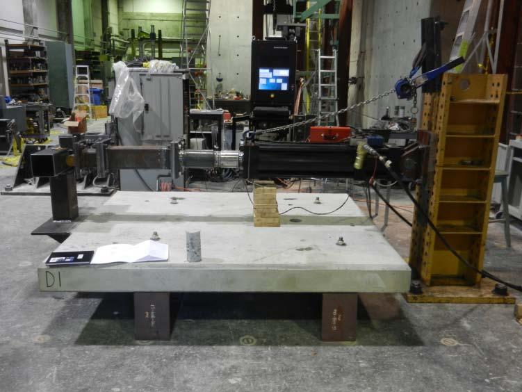
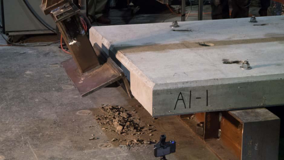
81 Testing Existing Barrier Configurations The University of British Columbia (UBC) tested the Ministry s existing barrier configurations to determine the static lateral capacity of the barrier and/or barrier anchorage to typical Ministry concrete deck panels.
82 Testing Existing Barrier Configurations The University of British Columbia (UBC) tested the Ministry s existing barrier configurations to determine the static lateral capacity of the barrier and/or barrier anchorage to typical Ministry concrete deck panels. It should be noted that some of the following information is not presented in chronological order, the nature of the work involved multiple revisions and phases of testing. The material is presented in a manner that groups similar test together to enable the viewers to visualize the results as a whole.
83 Experimental Set-Up


84 Existing Barrier - Results Timber Curb Systems Barrier Configuration Specimen ID Capacity (kn) 1 Theoretical Capacity (kn) 1,4 Bolt Grade 2 Failure Mechanism Timber Curb Block Timber Barrier on Side Mounted Steel Bracket A307 Failure in Timber 1.8 A307 Failure in Timber Timber Curb Block Timber Curb on Steel Bracket
85 Timber Curb Block - Test Video
86 Classifying Timber Curb Barriers The experimental values for the Timber Curbs shown below. Barrier Configuration Specimen ID Capacity (kn) 1 Theoretical Capacity (kn) 1,4 Bolt Grade 2 Failure Mechanism Timber Curb Block 1.8 A307 Failure in Timber Timber Barrier on Side A307 Failure in Timber Mounted Steel Bracket It is difficult to determine the capacity of timber barriers numerically.
87 Classifying Timber Curb Barriers The experimental values for the Timber Curbs shown below. Barrier Configuration Specimen ID Capacity (kn) 1 Theoretical Capacity (kn) 1,4 Bolt Grade 2 Failure Mechanism Timber Curb Block 1.8 A307 Failure in Timber Timber Barrier on Side A307 Failure in Timber Mounted Steel Bracket It is difficult to determine the capacity of timber barriers numerically. The tested capacities offer minimal lateral resistance (AASHTO s TL-1 = 60kN).
88 Classifying Timber Curb Barriers The experimental values for the Timber Curbs shown below. Barrier Configuration Specimen ID Capacity (kn) 1 Theoretical Capacity (kn) 1,4 Bolt Grade 2 Failure Mechanism Timber Curb Block 1.8 A307 Failure in Timber Timber Barrier on Side A307 Failure in Timber Mounted Steel Bracket It is difficult to determine the capacity of timber barriers numerically. The tested capacities offer minimal lateral resistance (AASHTO s TL-1 = 60kN). As Timber Curbs are performing adequately in the field, the Ministry opted to classify them as CL-1 barriers, but; Provide no design forces for CL-1 barriers in the Factored Barrier Design Force table. Provide Standard Drawing s which must be used by designers for CL-1 specified bridge barriers.

 Specimen ID Experimental")


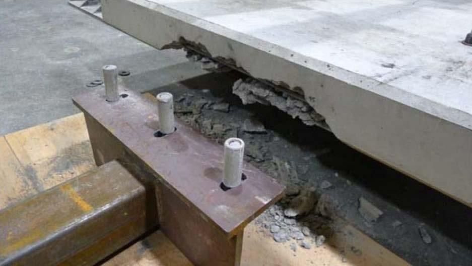
89 Existing Barrier - Results Top and/or Side Mounted Steel Bracket Systems Barrier Configuration Side-Mounted HSS Barrier (680mm Connection Bracket) Top & Side-Mounted HSS Barrier (680mm Connection Bracket) Specimen ID Experimental Capacity (kn) Theoretical Capacity (kn) 1 Bolt Grade 2 Failure Mechanism 47 A A325 Bracket Bolts Rupture in Tension Spalling of the Concrete in the Vicinity of the Inserts N/A A307 Deck Fails in Block Shear Side Mounted Steel Bracket Top & Side Mounted Steel Bracket
90 Side-Mounted Steel Bracket- Test Video
91 Classifying Side-Mounted Steel Bracket The experimental values for the Side-Mounted Steel Bracket are shown: Barrier Configuration Side-Mounted HSS Barrier (680mm Connection Bracket) Specimen ID Experimental Capacity (kn) Theoretical Capacity (kn) 1 Bolt Grade 2 Failure Mechanism 47 A A325 The numerical resistance consistently underestimates the bracket capacity. Bracket Bolts Rupture in Tension Spalling of the Concrete in the Vicinity of the Inserts
92 Classifying Side-Mounted Steel Bracket The experimental values for the Side-Mounted Steel Bracket are shown: Barrier Configuration Side-Mounted HSS Barrier (680mm Connection Bracket) Specimen ID Experimental Capacity (kn) Theoretical Capacity (kn) 1 Bolt Grade 2 Failure Mechanism 47 A A325 The numerical resistance consistently underestimates the bracket capacity. The bracket appears to be capable of achieving a 60 kn lateral resistance. Bracket Bolts Rupture in Tension Spalling of the Concrete in the Vicinity of the Inserts
93 Classifying Side-Mounted Steel Bracket The experimental values for the Side-Mounted Steel Bracket are shown: Barrier Configuration Side-Mounted HSS Barrier (680mm Connection Bracket) Specimen ID Experimental Capacity (kn) Theoretical Capacity (kn) 1 Bolt Grade 2 Failure Mechanism 47 A A325 The numerical resistance consistently underestimates the bracket capacity. The bracket appears to be capable of achieving a 60 kn lateral resistance. A variation in bolt grade changes the failure mechanism. Bracket Bolts Rupture in Tension Spalling of the Concrete in the Vicinity of the Inserts
94 Classifying Side-Mounted Steel Bracket The experimental values for the Side-Mounted Steel Bracket are shown: Barrier Configuration Side-Mounted HSS Barrier (680mm Connection Bracket) Specimen ID Experimental Capacity (kn) Theoretical Capacity (kn) 1 Bolt Grade 2 Failure Mechanism 47 A A325 The numerical resistance consistently underestimates the bracket capacity. The bracket appears to be capable of achieving a 60 kn lateral resistance. A variation in bolt grade changes the failure mechanism. Bracket Bolts Rupture in Tension Spalling of the Concrete in the Vicinity of the Inserts Based on the results, the Side-Mounted Steel Bracket was classified as a CL-2 barrier, and; Standard Drawing s were provided by the Ministry for CL-2 specified bridge barriers. Design forces were to be included in the Factored Barrier Design Force table to permit designers to create alternate CL-2 barrier details.


95 Side-Mounted Barrier Modifications Side Mounted Steel Bracket with Knee-Brace Modification During the original testing phase, UBC, at its own accord, modified the Side-Mounted HSS Barrier by adding a 600 mm long knee-brace, which projected under the concrete deck and engaged the girder flange. The photographs present the modified HSS Barrier with the kneebrace extending under the deck edge. Side Mounted Steel Bracket with Knee-Brace Modification
96 Knee-Braced Barrier - Results Side Mounted Steel Bracket with Knee-Brace Modification Barrier Configuration Specimen ID Capacity (kn) 1 Bolt Grade 2 Failure Mechanism A Capacities are based on a load application height of 450mm above the travelled surface. Bolt grade for bracket-to-deck connection only. Concrete compressive strength (f c) = 56 MPa. Modified Side-Mounted HSS Barrier (knee-brace) Concrete Failure at Panel Edge The experimental results for the modified Side-Mounted HSS Barrier are shown in the above Table. This modification resulted in the barrier capacity increasing by approximately 230% (compared to the Side-Mounted HSS Barrier). Modifications resulted in the barrier achieving the minimum required lateral resistance for a CL-3 classification barrier.
97 Knee-Brace Modification- Test Video
98 Implication of Knee-Brace Modification On review of the experimental data and specimen configuration it was established that a knee-brace of this length (600 mm) was impractical for field installations, since the knee-brace would rest on the girder flange making installation and accommodation of field tolerances difficult.
99 Implication of Knee-Brace Modification On review of the experimental data and specimen configuration it was established that a knee-brace of this length (600 mm) was impractical for field installations, since the knee-brace would rest on the girder flange making installation and accommodation of field tolerances difficult. A review of typical steel girder and concrete deck forestry bridges (in BC) suggests that the maximum practical lever arm is mm, which results in an increased demand on the anchor bolts.
100 Implication of Knee-Brace Modification On review of the experimental data and specimen configuration it was established that a knee-brace of this length (600 mm) was impractical for field installations, since the knee-brace would rest on the girder flange making installation and accommodation of field tolerances difficult. A review of typical steel girder and concrete deck forestry bridges (in BC) suggests that the maximum practical lever arm is mm, which results in an increased demand on the anchor bolts. Analysis concluded that a 400 mm knee-brace would result in an approximate transverse load capacity of 98 kn, which suggests that it does not meet the requirements for a CL-3 barrier, which requires a minimum of 120 kn.
101 Implication of Knee-Brace Modification On review of the experimental data and specimen configuration it was established that a knee-brace of this length (600 mm) was impractical for field installations, since the knee-brace would rest on the girder flange making installation and accommodation of field tolerances difficult. A review of typical steel girder and concrete deck forestry bridges (in BC) suggests that the maximum practical lever arm is mm, which results in an increased demand on the anchor bolts. Analysis concluded that a 400 mm knee-brace would result in an approximate transverse load capacity of 98 kn, which suggests that it does not meet the requirements for a CL-3 barrier, which requires a minimum of 120 kn. As a result, the Ministry opted to conduct a further development and experimental investigation to develop a new side-mounted barrier capable of achieving the design requirements for a CL-3 barrier, the details of which are discussed in the upcoming sections.
102 Conclusions of Phase 1 Testing Timber Curbs & W-Beams classified as CL-1 barrier Design forces excluded from the Factored Barrier Design Force table Designers only permitted to use Ministry standard drawings for CL-1 barriers
103 Conclusions of Phase 1 Testing Timber Curbs & W-Beams classified as CL-1 barrier Design forces excluded from the Factored Barrier Design Force table Designers only permitted to use Ministry standard drawings for CL-1 barriers Side-Mounted Steel Bracket HSS Barrier classified as CL-2 barrier Standard drawings provided by the Ministry for same Design forces provided to allow design of alternate systems and modifications to the rail.
104 Conclusions of Phase 1 Testing Timber Curbs & W-Beams classified as CL-1 barrier Design forces excluded from the Factored Barrier Design Force table Designers only permitted to use Ministry standard drawings for CL-1 barriers Side-Mounted Steel Bracket HSS Barrier classified as CL-2 barrier Standard drawings provided by the Ministry for same Design forces provided to allow design of alternate systems and modifications to the rail. Panel concrete strength (56 MPa) high o Conduct additional phase of testing to compare 40 MPa deck panel
105 Conclusions of Phase 1 Testing Timber Curbs & W-Beams classified as CL-1 barrier Design forces excluded from the Factored Barrier Design Force table Designers only permitted to use Ministry standard drawings for CL-1 barriers Side-Mounted Steel Bracket HSS Barrier classified as CL-2 barrier Standard drawings provided by the Ministry for same Design forces provided to allow design of alternate systems and modifications to the rail. Panel concrete strength (56 MPa) high o Conduct additional phase of testing to compare 40 MPa deck panel Drip groove (50 mm from deck edge) appeared to influence the panel edge capacity o Relocate drip groove 300 mm from deck edge
106 Conclusions of Phase 1 Testing Timber Curbs & W-Beams classified as CL-1 barrier Design forces excluded from the Factored Barrier Design Force table Designers only permitted to use Ministry standard drawings for CL-1 barriers Side-Mounted Steel Bracket HSS Barrier classified as CL-2 barrier Standard drawings provided by the Ministry for same Design forces provided to allow design of alternate systems and modifications to the rail. Panel concrete strength (56 MPa) high o Conduct additional phase of testing to compare 40 MPa deck panel Drip groove (50 mm from deck edge) appeared to influence the panel edge capacity o Relocate drip groove 300 mm from deck edge Grade A325 bolts result in panel edge failure (undesirable failure mechanism) o Barrier failure requires the panel to be replaced Grade A307 bolts result in bolt failure o Easier (& cheaper) replacement option o Use A307 bolts for Side-Mounted Steel Bracket HSS CL-2 barrier
107 Conclusions of Phase 1 Testing Timber Curbs & W-Beams classified as CL-1 barrier Design forces excluded from the Factored Barrier Design Force table Designers only permitted to use Ministry standard drawings for CL-1 barriers Side-Mounted Steel Bracket HSS Barrier classified as CL-2 barrier Standard drawings provided by the Ministry for same Design forces provided to allow design of alternate systems and modifications to the rail. Panel concrete strength (56 MPa) high o Conduct additional phase of testing to compare 40 MPa deck panel Drip groove (50 mm from deck edge) appeared to influence the panel edge capacity o Relocate drip groove 300 mm from deck edge Grade A325 bolts result in panel edge failure (undesirable failure mechanism) o Barrier failure requires the panel to be replaced Grade A307 bolts result in bolt failure o Easier (& cheaper) replacement option o Use A307 bolts for Steel Bracket CL-2 barrier Additional Modifications o Reduce bracket width from 680 mm to 550 mm o Incorporate bar anchors Location of Bar Anchors

108 CL-2 Barrier Tested Modifications Additional experimental phase with the following modifications to the CL-2 Side-Mounted HSS Barrier: 40 MPa panel concrete Drip groove located 300 mm from panel edge 550 mm and 680 mm wide bracket Grade A325 bolts used to ensure panel failure Bar anchors added to some specimens Grade A325 Bolts 550 mm & 680 mm TESTED
109 Refined CL-2 Barrier Test Results Barrier Configuration Specimen ID Capacity (kn) Bolt Grade Failure Mechanism A A B B C C C C Specimens with nuts attached to the rebar anchors. Side-Mounted HSS Barrier (680mm Connection Bracket) Side-Mounted HSS Barrier (550mm Connection Bracket) Side-Mounted HSS Barrier (680mm Connection Bracket) 1 The capacity of the side-mounted steel barrier appears sensitive to the compressive strength of the concrete. A325 A325 A307 A325 Spalling of the concrete in the vicinity of the inserts Spalling of the concrete in the vicinity of the inserts Bracket Bolts Rupture in Tension Spalling of the Concrete in the Vicinity of the Inserts
110 Refined CL-2 Barrier Test Results Barrier Configuration Specimen ID Capacity (kn) Bolt Grade Failure Mechanism A A B B C C C C Specimens with nuts attached to the rebar anchors. Side-Mounted HSS Barrier (680mm Connection Bracket) Side-Mounted HSS Barrier (550mm Connection Bracket) Side-Mounted HSS Barrier (680mm Connection Bracket) 1 The capacity of the side-mounted steel barrier appears sensitive to the compressive strength of the concrete. Reducing the bracket width from 680 mm to 550 mm reduces the connection resistance (mean values) by approximately 4%. A325 A325 A307 A325 Spalling of the concrete in the vicinity of the inserts Spalling of the concrete in the vicinity of the inserts Bracket Bolts Rupture in Tension Spalling of the Concrete in the Vicinity of the Inserts
111 Refined CL-2 Barrier Test Results Barrier Configuration Specimen ID Capacity (kn) Bolt Grade Failure Mechanism A A B B C C C C Specimens with nuts attached to the rebar anchors. Side-Mounted HSS Barrier (680mm Connection Bracket) Side-Mounted HSS Barrier (550mm Connection Bracket) Side-Mounted HSS Barrier (680mm Connection Bracket) 1 The capacity of the side-mounted steel barrier appears sensitive to the compressive strength of the concrete. Reducing the bracket width from 680 mm to 550 mm reduces the connection resistance (mean values) by approximately 4%. A 26% and 19% variation in experimental values exists for the 550 mm and 680 mm wide brackets respectively suggesting that the strength of the bracket is sensitive to fabrication tolerances, experimental set-up and testing and/or material variations. A325 A325 A307 A325 Spalling of the concrete in the vicinity of the inserts Spalling of the concrete in the vicinity of the inserts Bracket Bolts Rupture in Tension Spalling of the Concrete in the Vicinity of the Inserts
112 Refined CL-2 Barrier Test Results Barrier Configuration Specimen ID Capacity (kn) Bolt Grade Failure Mechanism A A B B C C C C Specimens with nuts attached to the rebar anchors. Side-Mounted HSS Barrier (680mm Connection Bracket) Side-Mounted HSS Barrier (550mm Connection Bracket) Side-Mounted HSS Barrier (680mm Connection Bracket) 1 The capacity of the side-mounted steel barrier appears sensitive to the compressive strength of the concrete. Reducing the bracket width from 680 mm to 550 mm reduces the connection resistance (mean values) by approximately 4%. A 26% and 19% variation in experimental values exists for the 550 mm and 680 mm wide brackets respectively suggesting that the strength of the bracket is sensitive to fabrication tolerances, experimental set-up and testing and/or material variations. Improving the anchorage of the embedded reinforcing anchors does not increase the resistance of the barrier. A325 A325 A307 A325 Spalling of the concrete in the vicinity of the inserts Spalling of the concrete in the vicinity of the inserts Bracket Bolts Rupture in Tension Spalling of the Concrete in the Vicinity of the Inserts
113 Refined CL-2 Barrier Test Results Barrier Configuration Specimen ID Capacity (kn) Bolt Grade Failure Mechanism A A B B C C C C Specimens with nuts attached to the rebar anchors. Side-Mounted HSS Barrier (680mm Connection Bracket) Side-Mounted HSS Barrier (550mm Connection Bracket) Side-Mounted HSS Barrier (680mm Connection Bracket) 1 The capacity of the side-mounted steel barrier appears sensitive to the compressive strength of the concrete. Reducing the bracket width from 680 mm to 550 mm reduces the connection resistance (mean values) by approximately 4%. A 26% and 19% variation in experimental values exists for the 550 mm and 680 mm wide brackets respectively suggesting that the strength of the bracket is sensitive to fabrication tolerances, experimental set-up and testing and/or material variations. Improving the anchorage of the embedded reinforcing anchors does not increase the resistance of the barrier. The Side-Mounted HSS Barrier (additional tests) is unable to meet the proposed requirements of a CL-2 barrier (60 kn) when the concrete deck strength is 40 MPa. A325 A325 A307 A325 Spalling of the concrete in the vicinity of the inserts Spalling of the concrete in the vicinity of the inserts Bracket Bolts Rupture in Tension Spalling of the Concrete in the Vicinity of the Inserts


114 Refined CL-2 Barrier Test Pictures
115 Conclusions of Refined CL-2 Testing Based on the findings it was concluded that the Ministry should modify the existing Side-Mounted HSS Barrier standard drawing to:
116 Conclusions of Refined CL-2 Testing Based on the findings it was concluded that the Ministry should modify the existing Side-Mounted HSS Barrier standard drawing to: Reduce the width of the bracket from 680 mm to 550 mm.
117 Conclusions of Refined CL-2 Testing Based on the findings it was concluded that the Ministry should modify the existing Side-Mounted HSS Barrier standard drawing to: Reduce the width of the bracket from 680 mm to 550 mm. Relocate the drip groove to 300 mm from the deck edge.
118 Conclusions of Refined CL-2 Testing Based on the findings it was concluded that the Ministry should modify the existing Side-Mounted HSS Barrier standard drawing to: Reduce the width of the bracket from 680 mm to 550 mm. Relocate the drip groove to 300 mm from the deck edge. Permit only the use of grade A307 bolts for barrier bracket-to-deck connections, to minimize the potential for deck edge failure.
119 Conclusions of Refined CL-2 Testing Based on the findings it was concluded that the Ministry should modify the existing Side-Mounted HSS Barrier standard drawing to: Reduce the width of the bracket from 680 mm to 550 mm. Relocate the drip groove to 300 mm from the deck edge. Permit only the use of grade A307 bolts for barrier bracket-to-deck connections, to minimize the potential for deck edge failure. The Factored Barrier Design Force was also revised to reflect the actual tested resistances of a CL-2 barrier from 60 kn to 45 kn. Regulatory Agency Proposed BC MFLNRO Revised BC MFLNRO Factored Design Criteria Containment Level CL-1 CL-2 CL-3 Transverse Load (kn) Longitudinal Load (kn) Vertical Load (kn) Load Application Height (mm) Transverse Load (kn) Longitudinal Load (kn) Vertical Load (kn) Load Application Height (mm)
120 CL-3 Barrier Development A further development and experimental investigation was conducted to develop a new side-mounted barrier capable of achieving the design requirements for a CL-3 barrier. None of the standard or tested barriers are capable of achieving the proposed CL-3 design criteria.
121 CL-3 Barrier Development A further development and experimental investigation was conducted to develop a new side-mounted barrier capable of achieving the design requirements for a CL-3 barrier. The results from the CL-2 tests indicated that the concrete in compression at the panel edge was the limiting strength factor (assuming adequate connection between the barrier and deck panel was provided).
122 CL-3 Barrier Development A prototype CL-3 barrier bracket was developed incorporating an embedded steel angle with vertical headed studs and horizontal Nelson Deformed Bars (NDB s).
123 CL-3 Barrier Development A prototype CL-3 barrier bracket was developed incorporating an embedded steel angle with vertical headed studs and horizontal Nelson Deformed Bars (NDB s). The embedded angle and vertical studs confine the concrete along the edge of the panel resulting in an increased compressive resistance.
124 CL-3 Barrier Development A prototype CL-3 barrier bracket was developed incorporating an embedded steel angle with vertical headed studs and horizontal Nelson Deformed Bars (NDB s). The embedded angle and vertical studs confine the concrete along the edge of the panel resulting in an increased compressive resistance. The horizontal NDB s provide the required tensile resistance.
125 Prototype CL-3 Barrier- Test Video
126 CL-3 Barrier Test Results The experimental results for the prototype CL-3 bracket are shown below. A review of the results indicates that: Barrier Configuration Specimen ID Capacity (kn) 1 Panel Thickness D D D mm D E Prototype CL-3 Side- Mounted HSS Barrier E E E mm Failure Mechanism Bond failure of short NDB s & fracture of the long NDB s
127 CL-3 Barrier Test Results The experimental results for the prototype CL-3 bracket are shown below. A review of the results indicates that: The connection does not consistently provide the required resistance for a CL-3 classification barrier for the 175 mm thick panel (120 kn required). Barrier Configuration Specimen ID Capacity (kn) 1 Panel Thickness D D D mm D E Prototype CL-3 Side- Mounted HSS Barrier E E E mm Failure Mechanism Bond failure of short NDB s & fracture of the long NDB s
128 CL-3 Barrier Test Results The experimental results for the prototype CL-3 bracket are shown below. A review of the results indicates that: The connection does not consistently provide the required resistance for the 175 mm thick panel. The connection provides sufficient resistance on the 200 mm thick panel. Barrier Configuration Specimen ID Capacity (kn) 1 Panel Thickness D D D mm D E Prototype CL-3 Side- Mounted HSS Barrier E E E mm Failure Mechanism Bond failure of short NDB s & fracture of the long NDB s
129 CL-3 Barrier Test Results During all the tests 3-4 popping sounds were noted, they coincided with the minor dips in resistance on the ascending branch of the load-displacement plot.
130 CL-3 Barrier Test Results During all the tests 3-4 popping sounds were noted, they coincided with the minor dips in resistance on the ascending branch of the load-displacement plot. Based on the load displacement plot and post-failure observations, it is believed that the popping sounds were associated with the bond failure of the four short NDB s.

131 CL-3 Barrier Test Results During all the tests 3-4 popping sounds were noted, they coincided with the minor dips in resistance on the ascending branch of the load-displacement plot. Based on the load displacement plot and post-failure observations, it is believed that the popping sounds were associated with the bond failure of the four short NDB s. The connection achieved peak load after bond failure of the short NDB s and prior to the fracture of one or more of the long NDB s at the weld location. It is believed that if the short NDB s had adequate anchorage (bond length), the connection may have achieved a higher peak resistance.

132 Modified CL-3 Barrier Configuration To increase the resistance of the prototype bracket, the four short NDB s were replaced with four pairs of stacked headed studs. Short NDB s removed Stacked Studs Vertical Shear Studs Nelson Deformed Bars
133 Modified CL-3 Barrier- Test Video
134 Modified CL-3 Barrier Test Results Barrier Configuration Specimen ID Capacity (kn) 1 Panel Thickness D D D mm D E Prototype CL-3 Side- Mounted HSS Barrier Modified CL-3 Side- Mounted HSS Barrier E E E G G H H mm 175 mm 200 mm Failure Mechanism Bond failure of short NDB s & fracture of the long NDB s Flexural failure top concrete cover failed resulting in loss of anchorage to the stacked studs followed by concrete crushing in the vicinity of the inserts The above table includes the experimental results for both the Prototype and modified CL-3 bracket. The 175 and 200 mm deck panels are capable of consistently achieving the requirements of a CL-3 barrier (120 kn).
135 Modified CL-3 Barrier Test Results Barrier Configuration Specimen ID Capacity (kn) 1 Panel Thickness D D D mm D E Prototype CL-3 Side- Mounted HSS Barrier Modified CL-3 Side- Mounted HSS Barrier E E E G G H H mm 175 mm 200 mm Failure Mechanism Bond failure of short NDB s & fracture of the long NDB s Flexural failure top concrete cover failed resulting in loss of anchorage to the stacked studs followed by concrete crushing in the vicinity of the inserts The above table includes the experimental results for both the Prototype and modified CL-3 bracket. The 175 and 200 mm deck panels are capable of consistently achieving the requirements of a CL-3 barrier (120 kn). The modified CL-3 barrier connection failed due to yielding/pull-out of the stacked headed studs and NDB s, and the loss of the top cover concrete.
136 Modified CL-3 Barrier Test Results Barrier Configuration Specimen ID Capacity (kn) 1 Panel Thickness D D D mm D E Prototype CL-3 Side- Mounted HSS Barrier Modified CL-3 Side- Mounted HSS Barrier E E E G G H H mm 175 mm 200 mm Failure Mechanism Bond failure of short NDB s & fracture of the long NDB s Flexural failure top concrete cover failed resulting in loss of anchorage to the stacked studs followed by concrete crushing in the vicinity of the inserts The above table includes the experimental results for both the Prototype and modified CL-3 bracket. The 175 and 200 mm deck panels are capable of consistently achieving the requirements of a CL-3 barrier (120 kn). The modified CL-3 barrier connection failed due to yielding/pull-out of the stacked headed studs and NDB s, and the loss of the top cover concrete. This was followed by the compressive failure of the concrete on the underside of the panel and extensive rotation of the bracket.
137 Modified CL-3 Barrier Test Results Barrier Configuration Specimen ID Capacity (kn) 1 Panel Thickness D D D mm D E Prototype CL-3 Side- Mounted HSS Barrier Modified CL-3 Side- Mounted HSS Barrier E E E G G H H mm 175 mm 200 mm Failure Mechanism Bond failure of short NDB s & fracture of the long NDB s Flexural failure top concrete cover failed resulting in loss of anchorage to the stacked studs followed by concrete crushing in the vicinity of the inserts The above table includes the experimental results for both the Prototype and modified CL-3 bracket. The 175 and 200 mm deck panels are capable of consistently achieving the requirements of a CL-3 barrier (120 kn). The modified CL-3 barrier connection failed due to yielding/pull-out of the stacked headed studs and NDB s, and the loss of the top cover concrete. This was followed by the compressive failure of the concrete on the underside of the panel and extensive rotation of the bracket. The NDB s did not fracture during any of the tests.


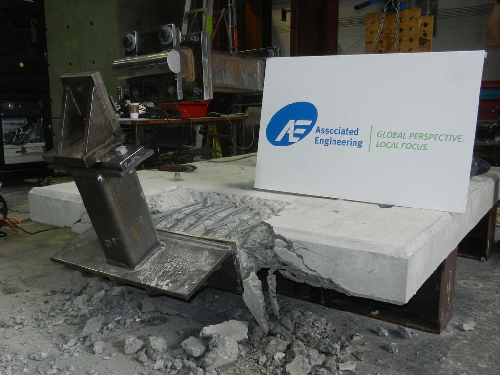
138 CL-3 Failure Comparison Panels D & E (only NDB reinforcement) Panels G & H (stacked studs & NDB reinforcement)
")
 Fractured NDB")

139 CL-3 Failure Comparison Panels D & E (only NDB reinforcement) Panels G & H (stacked studs & NDB reinforcement) Fractured NDB s Orientation of Stacked Headed Studs Orientation of Panel Reinforcement
140 CL-3 Load-Displacement Comparison Comparing the load-displacement plots for the prototype and modified CL-3 configurations: NDB s Stacked Studs The Stacked Stud Anchor System fails in a brittle manner compared to the ductile failure of the NDB Anchor System.
141 CL-3 Load-Displacement Comparison Comparing the load-displacement plots for the prototype and modified CL-3 configurations: NDB s Stacked Studs The Stacked Stud Anchor System fails in a brittle manner compared to the ductile failure of the NDB Anchor System. This is typical for the failure of an embedded stud. The failure leads to a sudden drop in resistance, at yield/failure, compared to a prolonged yielding plateau for the prototype configuration incorporating only NDB reinforcement.
142 CL-3 Load-Displacement Comparison Comparing the load-displacement plots for the prototype and modified CL-3 configurations: NDB s Stacked Studs The Stacked Stud Anchor System fails in a brittle manner compared to the ductile failure of the NDB Anchor System. Brittle failure is not a concern if the post and rail assembly is designed to yield prior to failure of the bracket. The connection provides sufficient over-strength (> 120 kn), to facilitate the design of a post and rail assembly that will yield prior to failure of the embedded bracket.
143 Conclusions of Modified CL-3 Testing Based on the findings a Standard Details Drawing for Side- Mounted CL-3 barriers was created for the Ministry incorporating the following:
144 Conclusions of Modified CL-3 Testing Based on the findings a Standard Details Drawing for Side- Mounted CL-3 barriers was created for the Ministry incorporating the following: A 680 mm wide bracket.
145 Conclusions of Modified CL-3 Testing Based on the findings a Standard Details Drawing for Side- Mounted CL-3 barriers was created for the Ministry incorporating the following: A 680 mm wide bracket. Grade A325 bolts for barrier bracket-to-deck connections.
146 Conclusions of Modified CL-3 Testing Based on the findings a Standard Details Drawing for Side- Mounted CL-3 barriers was created for the Ministry incorporating the following: A 680 mm wide bracket. Grade A325 bolts for barrier bracket-to-deck connections. An Embedded steel anchor identical to the Modified CL-3 details.
147 Conclusions of Modified CL-3 Testing Based on the findings a Standard Details Drawing for Side- Mounted CL-3 barriers was created for the Ministry incorporating the following: A 680 mm wide bracket. Grade A325 bolts for barrier bracket-to-deck connections. An Embedded steel anchor identical to the Modified CL-3 details. Drip groove located 300 mm from the deck edge.
148 CL-3 Barriers for Concrete Slab Bridges Based on the research discussed in this presentation a CL-3 barrier standard drawing was developed for concrete slab bridges.
149 CL-3 Barriers for Concrete Slab Bridges Based on the research discussed in this presentation a CL-3 barrier standard drawing was developed for concrete slab bridges. As slabs are typically 300 mm in depth, they provide considerably more depth to resist the barrier loads than typical deck panel slabs ( mm). 170 mm 55 mm Typical Slab Typical Deck Panel
150 CL-3 Barriers for Concrete Slab Bridges Based on the research discussed in this presentation a CL-3 barrier standard drawing was developed for concrete slab bridges. As slabs are typically 300 mm in depth, they provide considerably more depth to resist the barrier loads than typical deck panel slabs ( mm). As discussed earlier, the limiting factor for concrete deck panel was the concrete in compression at the panel edge (assuming adequate connection between the barrier and deck panel was provided). Concrete Compression Region Concrete Compression Region 170 mm 55 mm Typical Slab Typical Deck Panel
151 CL-3 Barriers for Concrete Slab Bridges As a result of the increased depth (for precast slabs), we were able to achieve the requirements of a CL-3 classification barrier using the CL-2 bracket details previously developed, with the following modifications: o 4 bolt inserts, similar to CL-3 details o Deeper bracket to engage full slab depth o Identical post/rail details as CL-3 barrier for concrete deck panels
152 Acknowledgements The work presented in this presentation is part of an ongoing research and development assignment directed by Associated Engineering BC Ltd. The University of British Columbia (UBC) conducted all fullscale testing. The project was financed by the BC Ministry of Forests, Lands and Natural Recourse Operations (MFLNRO). The assistance from Prof. Sigi Stiemer, Brook Robazza and Grant Fraser is gratefully acknowledged in the development of this research.

153


154 Hawk-Eye!!!

155 Questions?
Phase III Guideline for Barrier Selection and Design
 R E P O R T P R O P O S A L AUGUST 2011 BRITISH COLUMBIA Ministry of Forests, Lands and Natural Resource Operations Phase III Guideline for Barrier Selection and Design REPORT Table of Contents SECTION
Experimental Evaluation of Guard Rail Systems for Bridges
 Experimental Evaluation of Guard Rail Systems for Bridges For Ministry of Forests and Range, Engineering Branch, Field Operations Division (MoFR) Vancouver - July 15, 2010 By C. Villiard, M. Khorasani,
Barriers and highway accessory supports
 12.4 BARRIERS... 2 12.4.1 General... 2 12.4.2 Barrier joints... 3 12.4.3 Traffic barriers... 3 12.4.3.2 Test level... 3 12.4.3.2.1 General... 3 12.4.3.2.5 Test level for barriers on low volume roads...
Project Experimental Evaluation of Concrete Decks with Guard Rail Systems for Ministry of Forests, Lands and Natural Resource Operations
 UBC: CV/CD/MA/JS/SFS Project Experimental Evaluation of Concrete Decks with Guard Rail Systems for Ministry of Forests, Lands and Natural Resource Operations Project Report by C. Villiard & C. Dickof &
AS THE EFFECT ON BRIDGE BARRIERS
 ABSTRACT AS5100.2 2017 THE EFFECT ON BRIDGE BARRIERS David Coe, Senior Principal, Pitt & Sherry The revision to AS5100 in 2017 resulted in significant changes to the design loading and impact heights for
Ministry of Forests & Range
 Ministry of Forests & Range DRAWING SCHEDULE DRAWING No. / MODEL TYPE STD-EC-040-01 STD-EC-040-02 STD-EC-040-03 STD-EC-040-04 STD-EC-040-05 STD-EC-040-06 STD-EC-040-07 STD-EC-040-08 DESCRIPTION REV. DATE
Crash-Tested Bridge Railings for Timber Bridges
 In: Proceedings of 4th International bridge engineering conference; 1995 August 28 30; San Francisco, CA. Washington, DC: National Academy Press: 395-404; 1995. Vol. 2. Crash-Tested Bridge Railings for
Changes to the following sections of Tollway Structure Design Manual shall apply:
 DESIGN BULLETIN No. 18-02 Changes to the following sections of Tollway Structure Design Manual shall apply: 1. Section 7.1.4 Note 25. (Revise to) Horizontal design loads for retaining walls with moment
Chapter 1. General Design Information. Section 1.02 Structure Selection and Geometry. Introduction
 Chapter 1 Bridge Design Manual General Design Information Section 1.02 Selection and Geometry Introduction Selection or Rehabilitation Report This section of the design manual provides guidance on the
DESIGN OF CAMPBELL ROAD OVERPASS IN KELOWNA. Yulin Gao, M.A.Sc., P.Eng., SNC-Lavalin Inc. Samson Chan, M.Eng., P. Eng., SNC-Lavalin Inc.
 DESIGN OF CAMPBELL ROAD OVERPASS IN KELOWNA Yulin Gao, M.A.Sc., P.Eng., SNC-Lavalin Inc. Samson Chan, M.Eng., P. Eng., SNC-Lavalin Inc. Paper prepared for presentation at the Bridges in a Climate of Change
COMMONWEALTH OF PENNSYLVANIA DEPARTMENT OF TRANSPORTATION BUREAU OF DESIGN
 GENERAL NOTES DESIGN TABLE NOTES INDEX OF SHEETS 1. ALL DIMENSIONS ARE IN MILLIMETERS UNLESS OTHERWISE NOTED. U.S. CUSTOMARY UNITS IN ( ) PARENTHESIS.. ALL "DESIGN" METRIC UNITS INDICATED ARE SOFT CONVERTED
How Loads Are Distributed
 LOAD DISTRIBUTION 1 LOAD DISTRIBUTION This section illustrate how load will transmit from the deck to the stringers. Determining the fraction of load carried by a loaded member and the remainder distributed
Chapter 4 Bridge Program Drawings
 Chapter 4 Bridge Program Drawings Section 4.10-Bridge Railing Introduction Steel bridge railing and concrete bridge barrier rail are installed along the edge of the bridge roadway to keep errant vehicles
PIER PROTECTION (VEHICLE COLLISION) September 13, 2018
 September 13, 2018") PIER PROTECTION (VEHICLE COLLISION) September 13, 2018 Table of contents 1 Introduction 4-7 2 Investigation 8-19 3 Redirect vs. Structural Resistance 20-21 4 Redirect 22-33 5 Structural Resistance 34-39
PIER PROTECTION (VEHICLE COLLISION) September 13, 2018 Table of contents 1 Introduction 4-7 2 Investigation 8-19 3 Redirect vs. Structural Resistance 20-21 4 Redirect 22-33 5 Structural Resistance 34-39
Section 13. Guidelines for the Design of Ground Mounted Sign Supports
 Section 13 BDC11MR-04 13.1 Introduction Highway signs fall into two main categories, which are subdivided as follows: 1. Overhead Signs a. Sign Bridge Structures (GO) b. Sign Cantilever Structures (GO)
Cast in place concrete parapet and Ministry standard sidewalk railing.
 BRIDGE INSPECTION BRIDGE NO./NAME 62-003A: Farwell Canyon FSR (21.00 KM) Inspection Date: September 12 th 2012 Inspected By: D. Chen, J. Rupar Gilliatt Year Built: 2007 Number of Spans: 3 Span Lengths:
The use of prefabricated elements and systems in
 Development of a precast concrete barrier wall system for bridge decks Gaurang Patel, Khaled Sennah, Hossein Azimi, Clifford Lam, and Reza Kianoush This paper presents a connection detail for precast concrete
Two Test Level 4 Bridge Railing and Transition Systems for Transverse Timber Deck Bridges
 University of Nebraska - Lincoln DigitalCommons@University of Nebraska - Lincoln Civil Engineering Faculty Publications Civil Engineering 2000 Two Test Level 4 Bridge Railing and Transition Systems for
GUARDRAIL WARRANTS FOR LOW VOLUME ROADS
 74 GUARDRAIL WARRANTS FOR LOW VOLUME ROADS Louis B. Stephens, P.E. INTRODUCTION Low volume roads present many challenges to highway engineers and public administrators. Although, by definition, these facilities
Field and Laboratory Performance of FRP Bridge Panels
 Field and Laboratory Performance of FRP Bridge s D. Stone, A. Nanni, & J. Myers University of Missouri Rolla, Rolla, Missouri, USA ABSTRACT: The objective of this research project is to examine the use
Cross Frame Design for Curved and Skewed Bridges
 Cross Frame Design for Curved and Skewed Bridges Using AASHTO LRFD, 8 th Edition Travis Butz, PE To View Presentation on Your Mobile Device: www.burgessniple.com/event/2018/otec Cross frames in the 8 th
APPENDIX D STRUCTURAL REPORT
 Toronto Transit Commission / City of Toronto SCARBOROUGH-MALVERN LIGHT RAIL TRANSIT TRANSIT PROJECT ASSESSMENT STUDY ENVIRONMENTAL PROJECT REPORT APPENDICES APPENDIX D STRUCTURAL REPORT IBI Group Scarborough
CHAPTER 4 GRADE SEPARATIONS AND INTERCHANGES
 CHAPTER 4 GRADE SEPARATIONS AND INTERCHANGES 4.0 INTRODUCTION The ability to accommodate high volumes of intersecting traffic safely and efficiently through the arrangement of one or more interconnecting
STANDARDIZED CONCRETE BRIDGES IN TEXAS. John Holt, PE, Texas Department of Transportation Ronald Medlock, PE, Texas Department of Transportation
 STANDARDIZED CONCRETE BRIDGES IN TEXAS John Holt, PE, Texas Department of Transportation Ronald Medlock, PE, Texas Department of Transportation ABSTRACT Standardized concrete bridge plans are used extensively
T-39 Thriebeam. Product Manual. NCHRP 350 Test Level 3 & 4 Compliant Barrier. Release 01/11
 T-39 Thriebeam NCHRP 350 Test Level 3 & 4 Compliant Barrier Product Manual T-39 is licensed to Ingal Civil Products by Trinity Industries Inc. of the U.S.A. www.ingalcivil.com.au T-39 Thriebeam NCHRP 350
Technical Memorandum: Road Safety Hardware Series. technical memorandum
 technical memorandum road safety hardware series Frequently Asked Questions - Barriers & Terminals TM-2000 October 2012 Purpose To provide a list of frequently asked questions with answers in regard to
MATERIAL SPECIFICATION FOR DECK JOINT ASSEMBLIES
 ONTARIO PROVINCIAL STANDARD SPECIFICATION METRIC OPSS.PROV 1210 NOVEMBER 2014 MATERIAL SPECIFICATION FOR DECK JOINT ASSEMBLIES TABLE OF CONTENTS 1210.01 SCOPE 1210.02 REFERENCES 1210.03 DEFINITIONS 1210.04
Barriers, Parapets, and Railings
 Barriers, Parapets, and Railings Arielle Ehrlich State Bridge Design Engineer May 17, 2017 Bridge Office mndot.gov/bridge MnDOT Vocabulary Is it a barrier, a parapet or a railing? BARRIER. It is concrete
Chapter 1. General Design Information. Section 1.03 Loads and Load Factors. Introduction. Load Modifying Factors
 Chapter 1 Bridge Design Manual General Design Information Section 1.03 Loads and Load Factors Introduction This section defines the loads and load factors to be used in structural analysis and design.
APPENDIX B ABC STRUCTURES DESIGN GUIDE
 APPENDIX B ABC STRUCTURES DESIGN GUIDE The Cohos Evamy Partners TABLE OF CONTENTS Page No. DISCLAIMER... I 1. STRUCTURAL DESIGN GUIDELINES... 1 2. GENERAL REQUIREMENTS (FIGURE B.2, STEP 1)... 1 3. GENERAL
Bridge Barriers Implementing the AS5100 Bridge Design Code Provisions
 Bridge Barriers Implementing the AS5100 Bridge Design Code Provisions By Vincenzo Colosimo, B.Eng, G.Dip.CE, G.Dip.ME, MICE. Bridge Loads Engineer VicRoads Design VicRoads SYNOPSIS Bridge Barriers have
49-2A Clear-Zone Width for New Construction or Reconstruction B Clear-Zone Adjustment Factor, K cz, for Horizontal Curve...
 49-2A Clear-Zone Width for New Construction or Reconstruction...6 49-2B Clear-Zone Adjustment Factor, K cz, for Horizontal Curve...6 49-2C Clear-Zone Transition for Curve Adjustment, Radius 3000 ft...6
The use of 0.5 and 0.6 in. (13 and 15 mm) diameter
 diameter") Benefits of using.7 in. (18 mm) diameter strands in precast, pretensioned girders: A parametric investigation Jessica Salazar, Hossein Yousefpour, Alex Katz, Roya Alirezaei Abyaneh, Hyun su Kim, David
Benefits of using.7 in. (18 mm) diameter strands in precast, pretensioned girders: A parametric investigation Jessica Salazar, Hossein Yousefpour, Alex Katz, Roya Alirezaei Abyaneh, Hyun su Kim, David
Peterborough County Road Safety Audit Guideline Pilot
 Peterborough County Pilot Table of Contents 1.0 Purpose... 3 2.0 Road Safety Audit Objectives... 3 3.0 Legal Issues... 3 4.0 Road Safety Audit Procedures... 4 4.1 Project Selection Criteria... 5 4.2 Scope...
NATIONAL ANNEX TO STANDARD. SFS-EN EUROCODE 1: ACTIONS ON STRUCTURES Part 1-7: General actions Accidental actions
 ANNEX 37 NATIONAL ANNEX TO STANDARD SFS-EN 1991-1-7 EUROCODE 1: ACTIONS ON STRUCTURES Part 1-7: General actions Accidental actions Preface This National Annex is used together with the Standard SFS-EN
BRIDGE GIRDERS TECHNICAL GUIDE
 ARMTEC.COM BRIDGE MATERIALS / / TECHNICAL GUIDE REGIONal SPECIFICATIONS / AB / MB / SK PRECAST CONCRETE GIRDERS AND BEAMS DESIGNED TO SUPPORT BRIDGE DECKS AND TRAFFIC LOADS Proven strength In-house engineering
CHAPTER 18 TEMPORARY ROADS AND BRIDGES
 Change #1 - Revised 12/12 CHAPTER 18 TEMPORARY ROADS AND BRIDGES 18.0 INTRODUCTION These guidelines are to be used to design temporary roads and bridges where traffic will be maintained at the construction
Dead Loads. Load Resistance ηγ i Q i ΦR n. Design Criteria. EGCE 406 Bridge Design III. Loads on Bridge Summary of Concepts.
 Design Criteria We want the load effects to be less than the resistance EGCE 406 Bridge Design III. Loads on Bridge Summary of Concepts This Section Load Resistance ηγ i Q i ΦR n Load Multiplier Nominal
Structural - Engineering Review Checklist
 Structural - Engineering Review Checklist Project: List Corridor Criteria ID Review Priority (H,M,L) TOPICS S-_-## Structural Design Codes, Manuals and Specifications 6.1.0 REFERENCES DESIRED Criteria
Safety in a Second Guardrail Testing
 BMT Fleet Technology Limited 21017.DB01 (Rev. DRAFT01) Safety in a Second Guardrail Testing Reference: 7830.FR (Issue 02) Date: 19 March 2012 BMT Fleet Technology Limited accepts no liability for any errors
Basic types of bridge decks
 Bridge Deck Slab 1 Introduction 2 Bridge deck provide the riding surface for traffic, support & transfer live loads to the main load carrying member such as girder on a bridge superstructure. Selection
GUIDERAILS INTRODUCTION DESIGN PURPOSE CHAPTER 12
 401 CHAPTER 12 GUIDERAILS INTRODUCTION The general intent of the highway engineer is to design a roadway in which the geometry creates a safe driving environment that does not require guiderail or median
RESILIENT INFRASTRUCTURE June 1 4, 2016
 RESILIENT INFRASTRUCTURE June 1 4, 2016 FATIGUE STRENGTH OF ANGLE-SHAPED TRANSVERSE CONNECTION FOR GFRP-REINFORCED PRECAST FULL-DEPTH DECK PANELS IN ACCELERATED BRIDGE CONSTRUCTION Mahmoud Sayed-Ahmed
STRUCTURAL MANUAL Ministry of Transportation Provincial Highways Management Division Highway Standards Branch Bridge Office September, 2016
 STRUCTURAL MANUAL Ministry of Transportation Provincial Highways Management Division Highway Standards Branch Bridge Office September, 2016 ISBN 978-1-4606-8646-1 The Queen s Printer for Ontario. Reproduced
Load capacity rating of an existing curved steel box girder bridge through field test
 109 Dongzhou Huang Senior Engineer IV TS Transportation Design South Florida Atkins North America Load capacity rating of an existing curved steel box girder bridge through field test Abstract This paper
B STEEL BEAM GUIDE RAIL - OPSS 721
 B721-2 - - OPSS 721 721-2.1 GENERAL Design guidance and a description of Steel Beam Guide Rail systems, including various types and treatments, are provided in the Roadside Design Manual (RDM). 721-2.2
CURVED STEEL I GIRDER BRIDGES RAMP GH OVER THE ERIE CANAL INTRODUCTION BEHAVIOR OF CURVED BRIDGES DIFFERENCES FROM STRAIGHT BRIDGES
 DIFFERENCES FROM STRAIGHT BRIDGES Torsion effects Flange lateral bending Global stability CURVED STEEL I GIRDER BRIDGES RAMP GH OVER THE ERIE CANAL Constructability concerns INTRODUCTION COMPARISON WITH
DESIGN OF TEMPLETON OVERPASS FOR THE CANADA LINE. Yulin Gao, M.A.Sc., P.Eng., SNC-Lavalin Inc. Samson Chan, M.Eng.,P.Eng., SNC-Lavain Inc.
 DESIGN OF TEMPLETON OVERPASS FOR THE CANADA LINE Yulin Gao, M.A.Sc., P.Eng., SNC-Lavalin Inc. Samson Chan, M.Eng.,P.Eng., SNC-Lavain Inc. Roger Woodhead, PhD, P.Eng., SNC-Lavain Inc. Paper prepared for
BIN-WALL BRIDGE ABUTMENTS PRODUCT GUIDE
 _ ARMTEC.COM BRIDGE MATERIALS / BIN-WALL BRIDGE ABUTMENTS BIN-WALL BRIDGE ABUTMENTS PRODUCT GUIDE LIGHTWEIGHT, GALVANIZED STEEL BIN-WALL BRIDGE ABUTMENTS SUPPORTS BRIDGE SUPER-STRUCTURES AND TRAFFIC LOADINGS
Use of Externally Bonded FRP Systems for Rehabilitation of Bridges in Western Canada
 Use of Externally Bonded FRP Systems for Rehabilitation of Bridges in Western Canada Robin Hutchinson, Gamil Tadros, Jadwiga Kroman, Sami Rizkalla Synopsis: Since its inception in 1995, the ISIS Canada
ROADSIDE SAFETY BARRIER ELEMENTS Module 3
 2 ROADSIDE SAFETY BARRIER ELEMENTS Module 3 3 Roadside Design Options 4 Expected Crash Reduction of Relocation of Fixed Objects Source: NCHRP Report 500, Vol 6, Exhibit V-26 Purpose of Safety Barriers
CONSTRUCTION SPECIFICATION FOR MODULAR BRIDGE STRUCTURES FOR TEMPORARY INSTALLATIONS
 ONTARIO PROVINCIAL STANDARD SPECIFICATION METRIC OPSS.MUNI 918 APRIL 2017 (formerly OPSS 918 Common, March 1998) Note: The MUNI implemented in April 2017 replaces OPSS 918 COMMON, March 1998 with no technical
Design and Construction of the SH58 Ramp A Flyover Bridge over IH70. Gregg A. Reese, PE, CE, Summit Engineering Group, Inc.
 Design and Construction of the SH58 Ramp A Flyover Bridge over IH70 Gregg A. Reese, PE, CE, Summit Engineering Group, Inc., Littleton, CO ABSTRACT: The SH58 Ramp A bridge in Golden, CO is the latest on
D D TYPE A1, A2 & B MICHIGAN DEPARTMENT OF TRANSPORTATION 5-40 CONNECTION. L4" x 4" x 3/8" Brace. C8 x 4.25 Strut. WT9 x 17.5.
 Sign length minus Adjust to avoid interference with sign legend A Deck fascia A 6" Equal Equal 6" Sign length (L) varies 6 to 12 PLAN 0 CONNECTION (DECK FASCIA) Angle connection assembly F Face of concrete
The construction technology of Chongqing Chaotianmen Bridge
 The construction technology of Chongqing Chaotianmen Bridge Zhongfu Xiang School of Civil Engineering & Architectures, Chongqing Jiaotong University, Chongqing, China Wei Xu China zhongtie major bridge
Protection Systems for New Concrete Bridge Decks
 Introduction Protection Systems for New Concrete Bridge Decks Bridge decks are the main structural component designed to carry vehicle traffic and transfer live loads to the girder system. While safely
Bridge articulation No. 1.04
 Bridge articulation Scope This Guidance Note gives advice on the selection of the articulation arrangements, the choice of bearing types and dispositions of bearings, for bridges where relative movement
SCCRTC- MP San Lorenzo River Bridge Walkway Widening Feasibility Report
 SCCRTC- MP 19.43 San Lorenzo River Bridge Walkway Widening Feasibility Report May 19, 2016 INTRODUCTION Jacobs Engineering Group was selected to provide a feasibility report for the Santa Cruz County Regional
Engineering Design Process: Structural Design
 Engineering Design Process: Structural Design Introduction Structural engineering is the design of structural elements and their connections that work together to support loads and maintain stability within
Structural Characteristics of New Composite Girder Bridge Using Rolled Steel H-Section
 Proc. Schl. Eng. Tokai Tokai Univ., Univ., Ser. ESer. E 41 (2016) (2016) - 31-37 Structural Characteristics of New Composite Girder Bridge Using Rolled Steel H-Section by Mohammad Hamid ELMY *1 and Shunichi
SINGLE STEEL BOX GIRDER BRIDGES FOR THE TERMINAL DEVELOPMENT PROJECT AT TORONTO PEARSON INTERNATIONAL AIRPORT. Srdjan Brasic, M.Sc., P.Eng.
 SINGLE STEEL BOX GIRDER BRIDGES FOR THE TERMINAL DEVELOPMENT PROJECT AT TORONTO PEARSON INTERNATIONAL AIRPORT Srdjan Brasic, M.Sc., P.Eng. UMA Engineering Ltd. Paper prepared for presentation at the Technical
Application of Ultra High Performance Concrete in Expediting the Replacement and Rehabilitation of Highway Bridges
 Application of Ultra High Performance Concrete in Expediting the Replacement and Rehabilitation of Highway Bridges Abstract M. Ataur Rahman, P.Eng., Ph.D. and Tyler McQuaker, P.Eng. Ministry of Transportation
Design and Implementation of the Manitoba Constrained-Width Tall Wall Barrier. Submitted by: Authors: Co-authors:
 Design and Implementation of the Manitoba Constrained-Width Tall Wall Barrier Submitted by: Authors: Harald P. Larsen, P.Eng. Roadside Safety Engineer Manitoba Infrastructure Traffic Engineering 420 215
Barrier systems on structures
 Page B 1 Appendix B Barrier systems on structures In this section Section Page B1 General B 2 B2 Types of barrier system and their applications B 2 B3 Barrier performance selection method B 5 B4 Barrier
Superstructure Guidelines
 Superstructure Guidelines The following are additional guidelines on using the following types of superstructure. Pre-stressed Concrete Beams To check beam size use the beam size chart. The chart was created
STATE OF NEW HAMPSHIRE DEPARTMENT OF TRANSPORTATION LOAD RATING REPORT GENERAL SULLIVAN BRIDGE - DOVER 200/023 OVER THE LITTLE BAY
 STATE OF NEW HAMPSHIRE DEPARTMENT OF TRANSPORTATION LOAD RATING REPORT GENERAL SULLIVAN BRIDGE - DOVER 200/023 OVER THE LITTLE BAY NEWINGTON-DOVER, 11238S August 15, 2016 Vanasse Hangen Brustlin, Inc.
Texas Transportation Institute The Texas A&M University System College Station, Texas
 1. Report No. FHWA/TX-05/9-8132-3 4. Title and Subtitle TESTING AND EVALUATION OF THE FLORIDA F SHAPE RIDGE RAILWITH REDUCED DECK THICKNESS 2. Government Accession No. 3. Recipient's Catalog No. 5. Report
The Main Street Bridge - Supporting Transportation Systems
 The Main Street Bridge - Supporting Transportation Systems October 28, 2015 So what is the Transportation System Project Background BACKGROUND N DOWNTOWN 70 70 SOUTH INNERBELT STUDY Existing Condition
ABC-UTC. Research Progress Report (Feasibility Study) Title: Alternative ABC Connections Utilizing UHPC. March, 2017
 Title: Alternative ABC Connections Utilizing UHPC. March, 2017") ABC-UTC Research Progress Report (Feasibility Study) Title: Alternative ABC Connections Utilizing UHPC ABSTRACT March, 2017 Accelerated Bridge Construction (ABC) is a method of bridge construction designed
ABC-UTC Research Progress Report (Feasibility Study) Title: Alternative ABC Connections Utilizing UHPC ABSTRACT March, 2017 Accelerated Bridge Construction (ABC) is a method of bridge construction designed
Information Guide. Full Highway Loading Bridges for Low Volume Roads Stringer Type
 Information Guide Full Highway Loading Bridges for Low Volume Roads Stringer Type Designed to handle a vehicle wheel loading of a CL 625 Ontario truck as per the CHBDC CAN / CSA S6 06 1. What are these
Specification Changes and Their Effect on Plans. Bridge Construction Issues. BRG VTC April, 2010
 Specification Changes and Their Effect on Plans Bridge Construction Issues BRG VTC April, 2010 Brian D. Merrill, P.E. BRG Construction & Maintenance Branch Also: Common Plan Review Items Revised Specifications
GEOMETRIC DESIGN CRITERIA for Non-freeway Resurfacing, Restoration, and Rehabilitation Projects
 GEOMETRIC DESIGN CRITERIA for Non-freeway Resurfacing, Restoration, and Rehabilitation Projects SEPTEMBER 1989 Arkansas State Highway and Transportation Department GEOMETRIC DESIGN CRITERIA for Non-freeway
Hamilton Rapid Transit Preliminary Design and Feasibility Study
 Hamilton Rapid Transit Preliminary Design and Feasibility Study B-LINE STRUCTURAL ASSESSMENT DESIGN BRIEF Version:1.0 Hamilton Rapid Transit Preliminary Design and Feasibility Study B-LINE STRUCTURAL ASSESSMENT
Structural Behavior and Design of Barrier- Overhang Connection in Concrete Bridge Superstructures Using AASHTO LRFD Method
 University of New Haven Digital Commons @ New Haven Civil Engineering Faculty Publications Civil Engineering 1 Structural Behavior and Design of Barrier- Overhang Connection in Concrete Bridge Superstructures
Two glulam slab girders, 365 mm x 1825 mm spaced at 3065 mm c/c.
 BRIDGE INSPECTION BRIDGE NO. N2-038: Findlay-Lavington FSR (12.60 KM) Inspection Date: September 25, 2012 Inspected By: R. Veitch, M. Hanson Year Built: 1982 Number of Spans: 1 Span Lengths: Superstructure
MICHIGAN DEPARTMENT OF TRANSPORTATION SPECIAL PROVISION FOR PREFABRICATED STEEL PEDESTRIAN BRIDGE, TYPE 1
 MICHIGAN DEPARTMENT OF TRANSPORTATION SPECIAL PROVISION FOR PREFABRICATED STEEL PEDESTRIAN BRIDGE, TYPE 1 OFS:MJF 1 of 10 APPR:JAB:POJ:09-29-18 FHWA:APPR:10-01-18 a. Description. This work consists of
Class Topics & Objectives
 EGCE 406: Bridge Design Design of Slab for Bridge Deck Praveen Chompreda, Ph.D. Mahidol University First Semester, 2010 Class Topics & Objectives Topics Objective Bridge Superstructures Students can identify
EGCE 406: Bridge Design
 EGCE 406: Bridge Design Design of Slab for Praveen Chompreda Mahidol University First Semester, 2006 Bridge Superstructure Outline Components of bridge Superstructure Types Materials Design of RC Deck
AUGUST 2016 LRFD BRIDGE DESIGN 3-1
 AUGUST 2016 LRFD BRIDGE DESIGN 3-1 3. LOADS AND LOAD FACTORS The loads section of the AASHTO LRFD Specifications is greatly expanded over that found in the Standard Specifications. This section will present
Behavior and Analysis of Horizontally Curved Composite Steel Girder Bridge System
 e-issn: 2278-1684, p-issn: 232-334X. PP 45-52 Behavior and Analysis of Horizontally Curved Composite Steel Girder Bridge System Gourav Gajrani 1, Dr. L. M. Gupta 2 1,2 (Department of App. Mechanics, VNIT,
B STEEL BEAM GUIDE RAIL - OPSS.PROV 721
 B721-2 - - OPSS.PROV 721 721-2.1 GENERAL Steel beam guide rail (SBGR) is a semi-rigid barrier system which restrains and redirects vehicles by a combination of beam bending (W-shaped steel section), tension,
Special Provision No. 999S28 June 2010 CONSTRUCTION SPECIFICATION FOR PRECAST PANELS FOR USE AS STAY-IN-PLACE DECK FORMS
 PRECAST PANEL STAY-IN-PLACE DECK FORMS FABRICATION Item No. PRECAST PANEL STAY-IN-PLACE DECK FORMS DELIVERY Item No. PRECAST PANEL STAY-IN-PLACE DECK PANELS ERECTION Item No. Special Provision No. 999S28
Network Wide Assessment of Bridge Barrier Safety
 Network Wide Assessment of Bridge Barrier Safety Andrew Sonnenberg National Bridge Engineering Manager, pitt&sherry Abstract: The need for higher performance bridge barriers has been reflected in changes
Proposed Modifications to the LRFD Design of U-Beam Bearings
 Proposed Modifications to the LRFD Design of U-Beam Bearings Charles D. Newhouse, Scott A. Bole, W. R. Burkett, Phillip T. Nash, Mostafa El-Shami Performed in Cooperation with the Texas Department of Transportation
2016 STRUCTURE INSPECTION APPRAISAL REPORT. Prepared For: THE CORPORATION OF THE TOWNSHIP OF AMARANTH COUNTY OF DUFFERIN
 2016 STRUCTURE INSPECTION APPRAISAL REPORT Prepared For: THE CORPORATION OF THE TOWNSHIP OF AMARANTH COUNTY OF DUFFERIN by K. SMART ASSOCIATES LIMITED 8 McIntyre Drive Kitchener ON N2R 1H6 August 2016
B R I D G E O F F I C E
 LRFD Bridge Design Manual BRIDGE OFFICE MANUAL 5-392 MINNESOTA DEPARTMENT OF TRANSPORTATION Bridge Office LRFD Bridge Design Manual MnDOT BRIDGE OFFICE LRFD Bridge Design Manual Minnesota Department of
Innovative Design of Precast/Prestressed Girder Bridge Superstructures using Ultra High Performance Concrete
 Innovative Design of Precast/Prestressed Girder Bridge Superstructures using Ultra High Performance Concrete Husham Almansour, Ph.D. and Zoubir Lounis, Ph.D., P. Eng. Paper prepared for presentation at
MICHIGAN DEPARTMENT OF TRANSPORTATION SPECIAL PROVISION FOR PREFABRICATED STEEL PEDESTRIAN BRIDGE, TYPE 2
 MICHIGAN DEPARTMENT OF TRANSPORTATION SPECIAL PROVISION FOR PREFABRICATED STEEL PEDESTRIAN BRIDGE, TYPE 2 OFS:MJF 1 of 10 APPR:JAB:POJ:09-29-18 FHWA:APPR:10-01-18 a. Description. This work consists of
Alberta Transportation Roadside Design Guide November 2016 APPENDIX E GUIDELINES FOR THE SELECTION AND DESIGN OF HIGH TENSION CABLE BARRIER SYSTEMS
 Alberta Transportation Roadside Design Guide November 2016 APPENDIX E GUIDELINES FOR THE SELECTION AND DESIGN OF HIGH TENSION CABLE BARRIER SYSTEMS APPENDIX E COVER PAGE November 2016 Alberta Transportation
Potential Solutions- Background: Current Designs. Potential Solutions. Goals for Design What are we concerned about?
 Potential Solutions Potential Solutions- Background: Current Designs Goals for Design What are we concerned about? Primary Goal: Get the deck on successfully Stability during deck pour Girder plumbness
Installation Manual. Orion. TL-3 Steel Barrier. VHD (v2)
") Installation Manual Orion TL-3 Steel Barrier VHD (v2) 300914 Table of Contents Orion Introduction.......... 3 Limitations & Warnings. 4 Before Installation..... 3 System Design & Design Considerations
Installation Manual Orion TL-3 Steel Barrier VHD (v2) 300914 Table of Contents Orion Introduction.......... 3 Limitations & Warnings. 4 Before Installation..... 3 System Design & Design Considerations
Example. Monday, October 19, 2015
 Example Monday, October 19, 2015 11:26 AM Using a prestressed Y4 beam with reinforced concrete deck slab as the deck example as shown in Fig.1; the deck having a 10 skew, a span of 20m and carrying a 7.3m
MICHIGAN DEPARTMENT OF TRANSPORTATION SPECIAL PROVISION FOR PREFABRICATED STEEL PEDESTRIAN BRIDGE, TYPE 2
 MICHIGAN DEPARTMENT OF TRANSPORTATION SPECIAL PROVISION FOR PREFABRICATED STEEL PEDESTRIAN BRIDGE, TYPE 2 OFS:MJF 1 of 10 APPR:JAB:POJ:07-07-17 FHWA:APPR:07-11-17 a. Description. This work consists of
The Most Advanced Name in Water Management Solutions TM. The most cost-effective slotted and trench surface drain systems.
 The Most Advanced Name in Water Management Solutions TM The most cost-effective slotted and trench surface drain systems. A sensible alternative to metal and concrete Since 1987, Duraslot surface drains
MDOT Camelback Bridge Example
 MDOT Camelback Bridge Example AASHTOWare Bridge Rating 6.4.1 July 8, 2013 Contents MDOT Camelback Bridge Example AASHTOWare Bridge Rating 6.4.1... 1 Background... 2 Assumptions/Limitations... 2 General
The Use of Eastern Cottonwood for Stress Laminated Sawn Lumber Bridges in Iowa. Paula Hilbrich Lee Michael Ritter
 The Use of Eastern Cottonwood for Stress Laminated Sawn Lumber Bridges in Iowa Paula Hilbrich Lee Michael Ritter Historical Reference 1988 Timber Bridge Initiative Legislation passed by Congress. Objective:
Draft. Not yet Approved
 2016 Part 3.2.5 Recommended Design Criteria and Functional/Operating Guidelines for Overhead Bridge and Cantilever Structures and Placement of Grade Crossing Warning Devices Revised 2017 (8 Pages) A. Purpose
Prestressed Concrete Structure Tutorial
 AASHTOWare BrD/BrR 6.8 Prestressed Concrete Structure Tutorial PS5 Void Prestressed Box Beam Example BrR and BrD Training PS5 Void Prestressed Box Beam Example From the Bridge Explorer create a new bridge
MASTER AGREEMENT FOR BRIDGE DESIGN SERVICES SCOPE OF WORK
 MASTER AGREEMENT FOR BRIDGE DESIGN SERVICES SCOPE OF WORK The professional services to be provided by the Consultant under this Agreement shall be as necessary to complete the required analyses, layouts,
Special Provision No. 915S03 December References, Materials, Construction, and Quality Assurance for Sign Support Structures
 STEEL MONOTUBE OVERHEAD SIGN SUPPORT STRUCTURES - Item No. STEEL COLUMN BREAKAWAY SIGN SUPPORT STRUCTURES - Item No. STEEL COLUMN NON-BREAKAWAY SIGN SUPPORT STRUCTURES - Item No. CANTILEVER STATIC SIGN