ROADSIDE SAFETY BARRIER ELEMENTS Module 3
|
|
|
- Lee Evans
- 6 years ago
- Views:
Transcription


1


2 2 ROADSIDE SAFETY BARRIER ELEMENTS Module 3
3 3 Roadside Design Options
4 4 Expected Crash Reduction of Relocation of Fixed Objects Source: NCHRP Report 500, Vol 6, Exhibit V-26
5 Purpose of Safety Barriers 5 Prevent a motorist from leaving the roadway and striking an object or terrain feature that is more hazardous, such as: 1. a steep embankment, 2. a pole or tree, 3. a bridge or culvert end, 4. a bridge pier, 5. opposing traffic, 6. or an overhead sign support.
6 Factors to Consider When Selecting a 6 Barrier 1. Structural integrity 2. Maximum lateral deflection 3. Initial cost 4. Maintenance / replacement costs 5. Time to repair 6. Inventory cost / modular aspect 7. Installation and removal difficulty 8. Aesthetic
7 Barrier Types 7 Roadside Barriers Median Barriers Bridge Railings
8 Barrier Main Objectives 8 1. Provide shield / prevent penetration in passenger compartment 2. Redirect vehicle 3. Reduce crash severity
9 Roadside Safety Selection Process 9 1) Performance requirements of the roadside safety device (barrier) 2) Barrier Warranting Process a. Embankments b. Roadside Obstacles c. Bystanders 3) Roadside Barrier Types 4) Median Barrier Types

10 10 1. National Cooperative Highway Research Program NCHRP Report 350 Test criteria and performance specifications for road safety devices FHWA adopted in Federal Register Became effective on NHS: For all Contracts LET after October 1, 1998 On all maintenance or force account work INSTALLED after October 1, 1998 Existing barriers may remain if they met earlier NCHRP Report 230 criteria
11 Barrier Structural Adequacy 11 Any test vehicle must be contained and redirected Controlled deflection of the barrier is acceptable
12 Occupant Risk 12 No penetration of the passenger compartment Passenger compartment should not be significantly deformed The 820-kg and 2000-kg test vehicles must remain upright after collision
13 More Occupant Risks Unrestrained Passenger Decelerations: Under 9 m/sec preferred 12 m/sec max Occupant deceleration over a 10 millisecond period: Should not exceed 15 G s 20 G s is allowable
14 Vehicle Trajectory 14 Should not intrude into adjacent traffic lanes Exit angle should be less than 60% of the impact angle
15 NCHRP 350 Crash Tests 15 Describes the vehicles to be used in testing, the test conditions, and the instrumentation that will be used in testing the hardware Testing criteria are hardware-specific that require multiple tests under different impact conditions Six levels of testing (TL1 to TL6) Levels 1, 2, and 3 - applicable for both permanent and temporary barriers used in work zones for car and pickup trucks Levels 4, 5, and 6 - intended for permanent barriers and considers truck vehicles
16 16 1. Performance Requirements (Table 5-1b 2011 RDG) Test level Vehicle Angle Speed TL-1 1,800lb car 20 o 30 mph TL-2 TL-3 4,400lb pickup truck 25 o 45 mph 60 mph TL-4 (mod. TL-3) TL-5 TL kip SUT 15 o 50 mph 80kip tractortrailer (van) 80kip tractortrailer (tanker) 15 o 50 mph 15 o 50 mph

17 17 NCHRP Report 350 Test Vehicle Test Matrix for Longitudinal Barriers (Table 5-1b RDG)
18 MASH Crash Tests 18 Retains the test level conventions established in NCHRP Report 350, but Incorporates changes in the requirements for testing: Test vehicles For TL-1, 2, and 3 standard testing vehicles used: a 1100 kg (2420 lb.) small car A 2270 kg (5000 lb.) pickup truck Both NCHRP Report 350 and MASH encourage the use of in-service evaluation as a method for verifying the crashworthiness of devices.

19 19 MASH Crash Test Matrix for Longitudinal Barriers (Table 5-1a RDG)


20 20 NCHRP 350 Test Levels 4-6 TL-4 Vehicle TL-5 Vehicle TL-6 Vehicle
21 NCHRP 350 TL Suggested Applications 21 Test Level TL-1 TL-2 Selection Criteria Work zones with low posted speed, and low volume local streets Work zones, and most local and collector roads with low posted speeds and a low number of heavy vehicles expected TL-3 TL-4 High speed arterials with low mixtures of heavy vehicles and with favorable site conditions High speed highways, freeways, expressways, and Interstate highways with a mixture of trucks and heavy vehicles TL-5 TL-6 Same locations as TL-4 where a significant percent of the ADT is made of large trucks or where there are unfavorable site conditions Same locations as TL-4 where a significant percent of the ADT is made of tanker trucks, and unfavorable site conditions exist
22 Recommended Barrier Performance 22 Low-volume / low speed: lower than TL-3 Passenger cars and light trucks for low severity impacts: TL-2 Poor geometrics, high volume, and heavy trucks: TL-4 or better


23 23 0:53 3:35 7:55 8:50 17:10 BARRIER FULL-SCALE CRASH TESTS
24 2. Barrier Warranting Process Determine the needed clear zone for the road 2. Identify and locate potential hazards Review road crash history Road Safety Audit Survey road user experience 3. Analyze safety strategies (6 options) 4. Evaluate the need for roadside and median barriers

25 2. Barrier Warrants 25 a. Embankments b. Roadside and median obstacles a. Bystanders
26 Barrier Warrants Benefit / cost analysis Evaluate design speed and traffic volume in relation to barrier need Remove or reduce area of concern so that it no longer requires shielding Install an appropriate barrier Leave the area of concern unshielded 2. Subjective analysis When hitting a obstacle or running off the road is considered more objectionable than the barrier itself Does not consider cost of installing a barrier vs. unshielded conditions
27 Benefit / Cost Analysis 27 Estimated benefits to be derived from a specific course of action are compared to the costs of implementing that action Benefit annual reduction of accident costs Number of crashes Crash severity Cost construction and annual maintenance costs

28 BENEFIT / COST ANALYSIS 28 RSAP: Roadside Safety Analysis Program NCHRP Report 492
29 2a. Embankments 2011 RDG Figure 5-1b. Comparative Barrier Consideration for Embankments (US Customary Units) 29
30 2b. Roadside Obstacles (Table RDG) 30 Figure 5-2. Barrier Guidelines for Non-Traversable Terrain and Roadside Obstacles Obstacle Guidelines Bridge piers, abutments, and railing ends Shielding generally needed. Judgment decision based on nature of fixed object and likelihood Boulders of impact. Culverts, pipes, headwalls Judgment decision based on size, shape and location of obstacle. Foreslopes and backslopes (smooth) Shielding generally needed. Foreslopes and backslopes (rough) Judgment decision based on likelihood of impact. Ditches (parallel) Refer to Figures 3-6 and 3-7. Ditches (transverse) Shielding generally needed if likelihood of head-on impact is high. Embankment Judgment decision based on fill height and slope (see Figure 5-1). Judgment decision based on relative smoothness of wall and Retaining walls anticipated maximum angle of impact Sign/ Luminaire supports Shielding generally needed for non-breakaway supports. Isolated traffic signals within clear zone on high-speed rural Traffic signal supports facilities may need shielding. Trees Judgment decision based on site-specific circumstance. Utility poles Shielding may be needed on a case-by-case basis. Judgment decision based on location and depth of water and Permanent bodies of water likelihood of encroachment.

31 31 Barrier Warrants for Low-Volume Low- Speed Roads (Federal Lands Highway)
32 2c. Bystanders 32 Particular situations that need special analysis Schools Business Residences Pedestrian Bicycles Motorcycles
33 33 Module 3 Review 1. Any barrier that has met Report 350 evaluation criteria may be used on the National Highway System (NHS) and can be expected to perform satisfactorily in all crashes. True or False?
34 34 Module 3 Review 2. Where do you think a test level 5 barrier would be most appropriate: a. In the median of an urban freeway b. On a bridge over a river c. On the outside shoulder of a long downgrade
35 35 Module 3 Review 3. Why is a decision to use barrier to shield an embankment oftentimes a difficult one? a. The AASHTO embankment warrants are overly simplistic b. It is often not obvious which would be worse: running down the slope or striking guardrail c. Both of the above
36 36 Traffic Safety Barrier System 1. Basic section 3. Transition section 2. Terminal 4. Bridge Railing
37 37 a. Flexible b. Semi-rigid c. Rigid 3. ROADSIDE BARRIER TYPES

38 How to Obtain the Information on the FHWA website: 38 Safety.fhwa.dot.org Roadway Departure Safety

39 39 Safety.fhwa.dot.org Roadside Hardware

40 40 Safety.fhwa.dot.org Longitudinal Barriers

41 Deflection Characteristics 41 a. Flexible systems The Acceptance Letters can be found under the fhwa website:

42 42 Keyword: Aesthetic Barriers
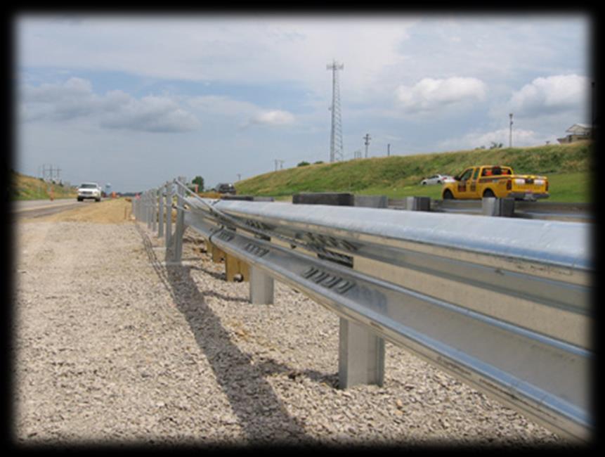
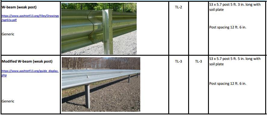
43 Deflection Characteristics 43 b. Semi-rigid systems
44 Keyword: Boxbeam Guardrail Terminal 44 Note the keywords are only meant to help the user sort out products that may suit the terrain, traffic volumes, travel speeds, highway geometry, etc. They are NOT intended as a formal classification system and should not be used as such. When considering any crash cushion or barrier terminal, the user is responsible for reading the FHWA letter and attachments and understanding any limitations noted, and for reviewing the manufacturer s literature to ensure proper selection, installation, and maintenance.
45 Deflection Characteristics 45 c. Rigid systems

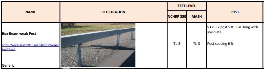
46 46 Keyword: Permanent Concrete Barriers

47 47 Flexible Barriers High impact deflections! 7 to 17 feet

48 Cable Barrier 48 High tension steel cables (3 and 4) mounted on weak posts Redirects vehicle after tension is developed in the cable Advantages Low initial cost Low deceleration forces Minimized sight distance problems Disadvantages Periodic monitoring of cable tension required More barrier damage in a typical accident Needs more clear area behind the barrier


49 49 Cable Barriers


50 W-Beam (Weak Post) 50 Behave like cable system, but with less deflection Posts serve primarily to hold the rail at the proper elevation Modified system w/ back-up plates tested at TL3 Advantages Low initial cost Low deceleration forces Disadvantages More barrier damage after a typical accident Vulnerable to vaulting Lateral deflection is m
51 W-beam (Flexible) 51
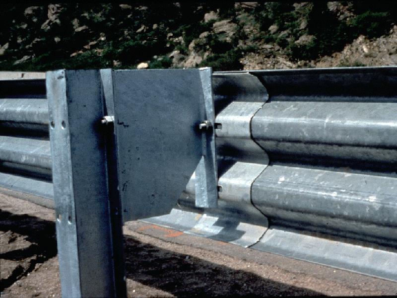
52 52 Semi-Rigid Barriers

53 53 Box Beam (Weak Post) Achieves resistance through combined flexural and tensile resistance of box beam Posts break away and distribute force to adjacent posts Disadvantages Sensitive to mounting height and soil irregularities Numerous parts and bolts may become a maintenance problem Relatively expensive weak-post barrier
54 54 Semi-rigid

55 55 Box beam system
56 56

57 57 W-Beam Post
58 58 Rail Deflection Characteristics, RDG Table 5-6

59 Blocked Out W-beam (Strong Post) 59 Minimizes vehicle snagging Reduces vaulting over barrier Achieves resistance through combined flexural and tensile stiffness of rail and shear strength of posts Tend to remain functional after moderate collisions

60 Blocked Out W-beam (Strong Post) 60 Moderate installation cost Moderate occupant forces Many options for local strengthening Moderate dynamic deflection Numerous propietary and non-propietary terminal and transitions
61 61


62 W-beam Guardrail w/ steel blocks 62 3:40

63 Rubber Block-out 63 Lightweight (8 pounds)
 eliminating need for offset blocks System height =")
64 T-31 W-Beam Guardrail 64 Proprietary, strong post w-beam W-beam attaches directly to Steel Yielding Line Posts (SYLP) eliminating need for offset blocks System height = 31
65 Blocked Out & Modified Thrie-beam 65 Similar to W-beam, but with deeper, stiffer, and additional corrugation rail Allows higher rail mounting, making it better able to contain larger vehicles Modified Thrie beam reduces likelihood that a vehicle roll over barrier Effective with large pick-up truck and school buses

66 66 Modified Thrie-beam


67 67 Modified Thrie-beam
 eliminating the need for off-set blocks System height =")
68 T-39 Thrie Beam Guardrail 68 Strong post Thrie-beam Thrie-beam attaches directly to Steel Yielding Line Posts (SYLP) eliminating the need for off-set blocks System height = 39 in

69 69 Thrie, Mod Thrie, T-39 Beams

70 70 Rigid Barriers Lateral deflection practically 0
71 71 F-shape and New Jersey Concrete Barriers
72 72

73 73 NJ concrete barrier
74 74 F-shape barrier
75 75
76 76
77 77

78 78 Single Slope Barrier
79 Tall Barrier 79 Height: 42 vs. 32 (traditional) Applications Highways with high percentage of heavy trucks (> 8%) Mountainous terrain with significantly steep longitudinal grades (> 6%)


80 80 Truck Trailer / Tanker Rigid Barrier 90

81 81 Solid concrete core masonry wall

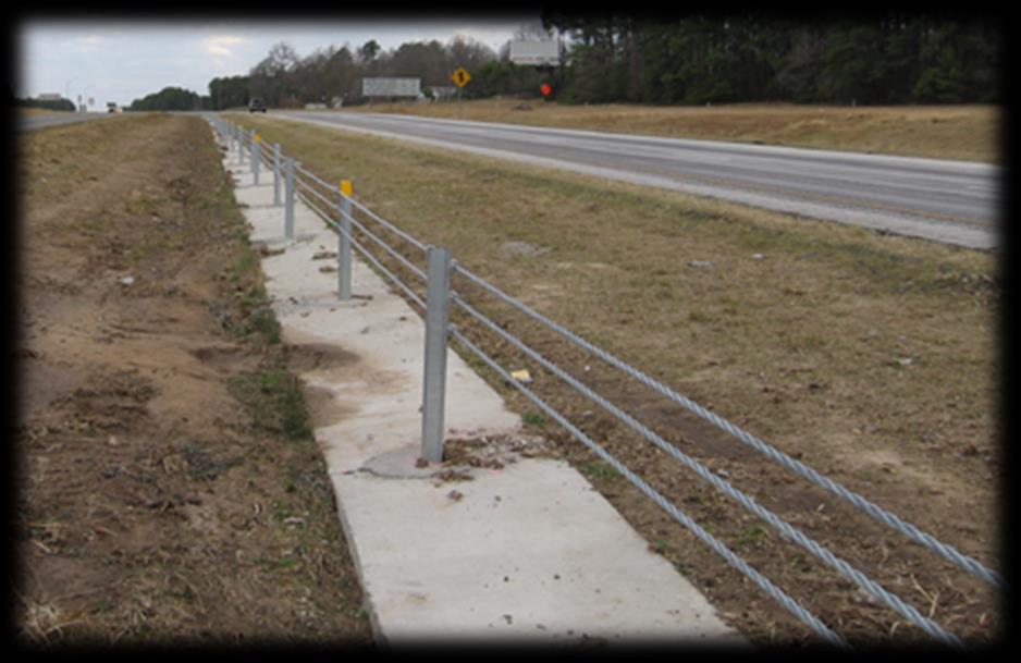
82 82 Roadside Barriers Selection Criteria
83 83 Roadside Barriers Selection Criteria


84 84 a. Flexible b. Semi-rigid c. Rigid 4. MEDIAN BARRIER TYPES
85 Median Barriers 85 Longitudinal barriers Separate opposing through traffic on high-volume divided highways Contain and redirect passenger vehicles and pick-up trucks NCHRP 350 Recommended Procedures for the Safety Performance Evaluation of Highway Features
86 86 Crashworthy Median Barrier Systems
87 1. Performance Requirements 87 Test level Vehicle Angle Speed TL-1 1,800lb car 20 o 30 mph TL-2 TL-3 4,400lb pickup truck 25 o 45 mph 60 mph TL-4 (mod. TL-3) TL-5 TL kip SUT 15 o 50 mph 80kip tractortrailer (van) 80kip tractortrailer (tanker) 15 o 50 mph 15 o 50 mph
88 Median Barrier Selection Guidelines 88 Performance: TL-3 Deflection distance approx. half median width Flexible and semi-rigid: wide and flat slopes Rigid: narrow medians Compatibility with other median features Costs Aesthetics and Environmental Field experience
89 89 AASHTO Guidelines for Median Barriers on High-Speed, Fully Controlled-Access Roadways
90 Deflection Characteristics 90 a. Flexible systems Median Cable Barrier W-beam (weak post) b. Semi-rigid systems Box beam Blocked out W- beam and Thrie beam (strong post) Modified Thrie beam c. Rigid systems (concrete or masonry) Safety shape F-shape Vertical Single-slope
91 Median Cable Barrier 91 Steel cables mounted on weak posts Redirects vehicle after tension is developed in the cable Mounting height of top cable is 30in and 12ft deflection distance Only for flat and traversable 1V:6H medians with no curb or ditches

92 92 Median Cable Barrier
93 W-Beam (Weak Post) 93 Behave like cable system, but with less deflection Posts serve primarily to hold the rail at the proper elevation Mounting height of 33in and 7ft deflection distance Only for flat and traversable medians with no curb or ditches

94 94 W-Beam (Weak Post)
95 Box Beam (Weak Post) 95 Achieves resistance through combined flexural and tensile resistance of box beam Posts break or tear away and distribute force to adjacent posts Deflection distance of 5.5 ft
")
96 96 Box Beam (Weak Post)
97 Blocked Out W-beam (Strong Post) 97 Minimizes vehicle snagging Reduces vaulting over barrier Mounting height of 30 in and 2 to 4 ft deflection distance Rub rail is added for curb applications

98 98 Blocked Out W-beam (Strong Post)
99 Blocked Out & Modified Thrie-beam 99 Similar to W-beam, but with deeper, stiffer, and additional corrugation rail Allows higher rail mounting, making it better able to contain larger vehicles Mounting height of 32 in and 1 to 3 ft deflection distance

100 100 Blocked Out & Modified Thrie-beam
101 Concrete Barriers 101 Most common rigid median barrier High-angle and high-speed impacts Airborne vehicle Reach top of wall Fixed objects on top of wall Snagging Separate from barrier Cargo box of high center of gravity vehicles may hit fixed objects over wall
102 Disadvantages of Rigid Barriers 102 Stability problems for some vehicles especially at extreme impact angles Vehicle redirection back into the roadway with little loss of speed High occupant forces Elaborate drainage structures required Reduction of effective height and lowering of slope breakpoint possible on pavement overlay
103 103
104 104 Median Barrier Selection Criteria
105 State Transportation Agency Median 105 Design and Safety Practices Approximately 76% of States have adopted AASHTO policy as median design barrier warrant standards Strong-post W-beam guardrail and concrete safety shape are the most commonly used Innovative strategies Rumble strips on the inside paved shoulder Median side slope flattening


106 106 Last Roadside Safety Design Option

107 107 QUESTIONS & REVIEW
108 108 Module 3 Review 4. Which barrier would you as a motorist prefer to hit? a. Strong-post w-beam b. 3-strand cable guardrail c. New Jersey concrete barrier
109 109 Module 3 Review 5. If you are in charge of highway maintenance, what barrier would you like to see used most often? a. Strong-post w-beam b. 3-strand cable guardrail c. New Jersey concrete barrier
GUIDERAILS INTRODUCTION DESIGN PURPOSE CHAPTER 12
 401 CHAPTER 12 GUIDERAILS INTRODUCTION The general intent of the highway engineer is to design a roadway in which the geometry creates a safe driving environment that does not require guiderail or median
Barriers, Parapets, and Railings
 Barriers, Parapets, and Railings Arielle Ehrlich State Bridge Design Engineer May 17, 2017 Bridge Office mndot.gov/bridge MnDOT Vocabulary Is it a barrier, a parapet or a railing? BARRIER. It is concrete
NOTES ON THE SPECIFICATION FOR ROAD SAFETY BARRIER SYSTEMS
 1. INTRODUCTION A road safety barrier is considered to be a hazard and should only be used when the consequences of hitting it are less than the hazard/object which it is shielding. The use of a road safety
49-2A Clear-Zone Width for New Construction or Reconstruction B Clear-Zone Adjustment Factor, K cz, for Horizontal Curve...
 49-2A Clear-Zone Width for New Construction or Reconstruction...6 49-2B Clear-Zone Adjustment Factor, K cz, for Horizontal Curve...6 49-2C Clear-Zone Transition for Curve Adjustment, Radius 3000 ft...6
600 Roadside Design. Table of Contents
 600 Roadside Design Table of Contents 600.1 Introduction... 6-1 600.2 Clear Zone... 6-1 600.2.1 Parallel Embankment Slopes & Ditches... 6-2 600.2.2 Urban Lateral Offsets... 6-2 600.2.3 Operational Offsets
H5 Roadside and Median Barrier Systems
 Alberta Infrastructure and Transportation Roadside Design Guide November 2007 H5 Roadside and Median Barrier Systems H5.1 Introduction Barrier systems can be classified into two categories, based on their
H5 Roadside and Median Barrier Systems
 Alberta Infrastructure and Transportation November 2007 H5 Roadside and Median Barrier Systems H5.1 Introduction Barrier systems can be classified into two categories, based on their location and design:
Section 8 -Guide Rail and Median Barriers
 Section 8-8.1 Introduction These guidelines are based on the Roadside Design Guide, AASHTO, 2011. The information in this section is intended to serve as guidelines that will assist the designer in determining
DESIGN GUIDE. Advancing Safety Through Innovation. TCC-DG01 07/18/02 Page 1
 DESIGN GUIDE Advancing Safety Through Innovation Patents Pending Copyright 2002 BSI TCC-DG01 07/18/02 Page 1 TAU-II Crash Cushion DESIGN Table of Contents Preface 22 Introduction 2 Important Information..
CHAPTER 3 SCOPE SUMMARY
 CHAPTER 3 SCOPE SUMMARY GENERAL The SDDOT is an active member of AASHTO to share common national design standards for the state highway system. The AASHTO Task Force on Geometric Design has completed the
LOCATION AND DESIGN DIVISION
 VIRGINIA DEPARTMENT OF TRANSPORTATION LOCATION AND DESIGN DIVISION INSTRUCTIONAL AND INFORMATIONAL MEMORANDUM GENERAL SUBJECT: ROADWAY SAFETY FEATURES SPECIFIC SUBJECT: NCHRP 350 TEST REQUIREMENTS LOCATION
Roadside Design Guide. Update from the Technical Committee on Roadside Safety Chris Poole, Iowa DOT
 Roadside Design Guide Update from the Technical Committee on Roadside Safety Chris Poole, Iowa DOT TCRS Strategic Plan Vision - Lead roadside policy development, support safety innovations, and be an information
Subject: ACTION: National Cooperative Highway Research Program (NCHRP) Report 350 Hardware Compliance Dates
 Report 350 Hardware Compliance Dates") Memorandum - FHWA Safety Program Page 1 of 2 Memorandum US Department of Transportation Federal Highway Administration Subject: ACTION: National Cooperative Highway Research Program (NCHRP) Report 350
Memorandum - FHWA Safety Program Page 1 of 2 Memorandum US Department of Transportation Federal Highway Administration Subject: ACTION: National Cooperative Highway Research Program (NCHRP) Report 350
LOCATION AND DESIGN DIVISION
 VIRGINIA DEPARTMENT OF TRANSPORTATION LOCATION AND DESIGN DIVISION INSTRUCTIONAL AND INFORMATIONAL MEMORANDUM GENERAL SUBJECT: ROADWAY SAFETY FEATURES SPECIFIC SUBJECT: NCHRP 350 TEST REQUIREMENTS LOCATION
GEOMETRIC DESIGN CRITERIA for Non-freeway Resurfacing, Restoration, and Rehabilitation Projects
 GEOMETRIC DESIGN CRITERIA for Non-freeway Resurfacing, Restoration, and Rehabilitation Projects SEPTEMBER 1989 Arkansas State Highway and Transportation Department GEOMETRIC DESIGN CRITERIA for Non-freeway
Alberta Transportation Roadside Design Guide February 2012 APPENDIX E GUIDELINES FOR THE SELECTION AND DESIGN OF HIGH TENSION CABLE BARRIER SYSTEMS
 Roadside Design Guide February 2012 GUIDELINES FOR THE SELECTION AND DESIGN OF HIGH TENSION CABLE BARRIER SYSTEMS COVER PAGE February 2012 Roadside Design Guide THIS PAGE INTENTIONALLY LEFT BLANK COVER
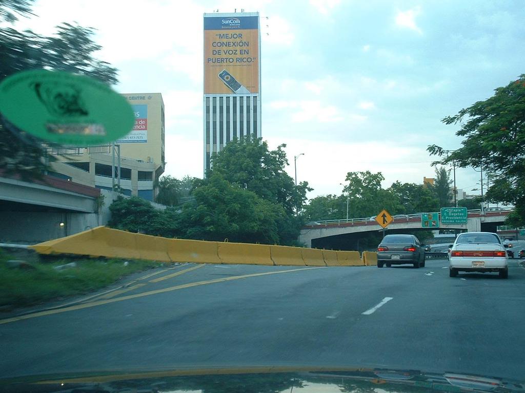
MASH Implementation Timeline. Ing. Juan Carlos Rivera Supervisor, División de Proyectos de Seguridad Vial
 MASH Implementation Timeline Ing. Juan Carlos Rivera Supervisor, División de Proyectos de Seguridad Vial MASH Agenda Differences between NCHRP 350 and MASH Joint Implementation Agreement for MASH Puerto
Section 13. Guidelines for the Design of Ground Mounted Sign Supports
 Section 13 BDC11MR-04 13.1 Introduction Highway signs fall into two main categories, which are subdivided as follows: 1. Overhead Signs a. Sign Bridge Structures (GO) b. Sign Cantilever Structures (GO)
Chapter 4 Bridge Program Drawings
 Chapter 4 Bridge Program Drawings Section 4.10-Bridge Railing Introduction Steel bridge railing and concrete bridge barrier rail are installed along the edge of the bridge roadway to keep errant vehicles
DESIGN BULLETIN #75/2012 (Rewritten October 2016)
") DESIGN BULLETIN #75/2012 (Rewritten October 2016) Alberta Roadside Design Guide High Tension Cable Barrier System Median and Roadside Installation October 27, 2016 Rewrite of Design Bulletin #75/2012 April
DESIGN BULLETIN #75/2012 (Rewritten October 2016) Alberta Roadside Design Guide High Tension Cable Barrier System Median and Roadside Installation October 27, 2016 Rewrite of Design Bulletin #75/2012 April
DESIGN BULLETIN #75/2012 (Revised April 2012)
") DESIGN BULLETIN #75/2012 (Revised April 2012) Alberta Roadside Design Guide High Tension Cable Barrier System Median and Roadside Installation April 5, 2012 Amendment to Design Bulletin #75/2012 - Section
DESIGN BULLETIN #75/2012 (Revised April 2012) Alberta Roadside Design Guide High Tension Cable Barrier System Median and Roadside Installation April 5, 2012 Amendment to Design Bulletin #75/2012 - Section
GUARDRAIL WARRANTS FOR LOW VOLUME ROADS
 74 GUARDRAIL WARRANTS FOR LOW VOLUME ROADS Louis B. Stephens, P.E. INTRODUCTION Low volume roads present many challenges to highway engineers and public administrators. Although, by definition, these facilities
Universal TAU-II Redirective, Non-Gating, Crash Cushion
 TB 010925 Rev. 2 Page 1 of 10 Product Specification Universal TAU-II Redirective, Non-Gating, Crash Cushion I. General The Universal TAU-II system is a Redirective, Non-Gating Crash Cushion in accordance
MASH 2016 Implementation- An AASHTO-FHWA Joint Plan
 MASH 2016 Implementation- An AASHTO-FHWA Joint Plan Presented by Chris Lindsey, TxDOT MASH 2016 Overview Background and Context MASH Implementation Agreement Availability of MASH Hardware Anticipated Costs
MICHIGAN DESIGN MANUAL ROAD DESIGN CHAPTER
 7.01 ROADSIDE SAFETY BARRIER 7.01.01 References 7.01.02 Application of Section 7.01 MICHIGAN DESIGN MANUAL CHAPTER 7 INDEX APPURTENANCES 7.01.03 History of Guardrail and Barrier in Michigan 7.01.04 Section
Chapter URBAN & RURAL FREEWAY DESIGN
 Chapter 5 URBAN & RURAL FREEWAY DESIGN 5.1 INTRODUCTION This chapter provides standards and guidance for urban and rural freeways on new construction/reconstruction projects. The chapter also provides
Section 1 - Introduction Introduction Policy on Use of AASHTO Standards Reference Publications... 2
 Table of Contents Section 1 - Introduction... 1 1.1 Introduction... 1 1.2 Policy on Use of AASHTO Standards... 2 1.3 Reference Publications... 2 Section 2 - General Design Criteria... 1 2.1 General...
B STEEL BEAM GUIDE RAIL - OPSS 721
 B721-2 - - OPSS 721 721-2.1 GENERAL Steel Beam Guide Rail (SBGR) is a semi-rigid barrier system which restrains and redirects vehicles by a combination of beam bending (W-shaped steel section), tension,
Practices for High-tension Cable Barriers. Presented to the AASHTO Subcommittee on Maintenance Providence, Rhode Island Wednesday, August 2, 2017
 Practices for High-tension Cable Barriers Presented to the AASHTO Subcommittee on Maintenance Providence, Rhode Island Wednesday, August 2, 2017 Synthesis Objectives To identify and report on the state
Product Specification ArmorGuard Barrier System
 TB 081030 Rev. 0 Page 1 of 6 Product Specification ArmorGuard Barrier System I. General The ArmorGuard Barrier System is a longitudinal barrier, as defined in the AASHTO Roadside Design Guide, which can
Corrugated Guardrail and Box Beam Barriers
 HIGHWAY SAFETY CORPORATION PRODUCT SHOWCASE Highway Safety Corporation has been serving the highway construction industry for over 30 years. We are a major manufacturer and supplier of highway guardrail
Alberta Transportation Roadside Design Guide November 2016 APPENDIX E GUIDELINES FOR THE SELECTION AND DESIGN OF HIGH TENSION CABLE BARRIER SYSTEMS
 Alberta Transportation Roadside Design Guide November 2016 APPENDIX E GUIDELINES FOR THE SELECTION AND DESIGN OF HIGH TENSION CABLE BARRIER SYSTEMS APPENDIX E COVER PAGE November 2016 Alberta Transportation
B STEEL BEAM GUIDE RAIL - OPSS.PROV 721
 B721-2 - - OPSS.PROV 721 721-2.1 GENERAL Steel beam guide rail (SBGR) is a semi-rigid barrier system which restrains and redirects vehicles by a combination of beam bending (W-shaped steel section), tension,
T-39 Thriebeam. Product Manual. NCHRP 350 Test Level 3 & 4 Compliant Barrier. Release 01/11
 T-39 Thriebeam NCHRP 350 Test Level 3 & 4 Compliant Barrier Product Manual T-39 is licensed to Ingal Civil Products by Trinity Industries Inc. of the U.S.A. www.ingalcivil.com.au T-39 Thriebeam NCHRP 350
Technical Memorandum: Road Safety Hardware Series. technical memorandum
 technical memorandum road safety hardware series Frequently Asked Questions - Barriers & Terminals TM-2000 October 2012 Purpose To provide a list of frequently asked questions with answers in regard to
SUBJECT: Discussion Regarding Barriers & Barrier Transitions with Staff from the Midwest Roadside Safety Facility (Univ of Nebraska, Lincoln)
") Problem # 8 MnDOT Questions Regarding Bridge Barriers State Question and MwRSF Response: MnDOT had a conference call with MwRSF to discuss various questions regarding barriers on superelevations and cross
Problem # 8 MnDOT Questions Regarding Bridge Barriers State Question and MwRSF Response: MnDOT had a conference call with MwRSF to discuss various questions regarding barriers on superelevations and cross
Bridge Barriers Implementing the AS5100 Bridge Design Code Provisions
 Bridge Barriers Implementing the AS5100 Bridge Design Code Provisions By Vincenzo Colosimo, B.Eng, G.Dip.CE, G.Dip.ME, MICE. Bridge Loads Engineer VicRoads Design VicRoads SYNOPSIS Bridge Barriers have
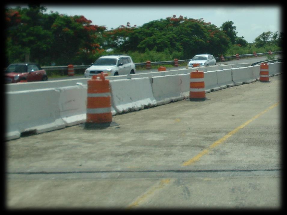
APPENDIX A GUIDELINES FOR THE USE OF BARRIER/CHANNELIZING DEVICES IN WORK ZONES INTRODUCTION
 May 20, 2011 Draft A-1 APPENDIX A GUIDELINES FOR THE USE OF BARRIER/CHANNELIZING DEVICES IN WORK ZONES INTRODUCTION A. The following safety guidelines have been developed to provide a methodical framework
MASH. When most people hear MASH, they think of the popular. Regulation CODES & STANDARDS
 CODES & STANDARDS MASH provides guidelines for crashtesting roadside barriers, including precast concrete barriers. It also recommends evaluation criteria to assess these test results. Photo courtesy of
AS THE EFFECT ON BRIDGE BARRIERS
 ABSTRACT AS5100.2 2017 THE EFFECT ON BRIDGE BARRIERS David Coe, Senior Principal, Pitt & Sherry The revision to AS5100 in 2017 resulted in significant changes to the design loading and impact heights for
B STEEL BEAM GUIDE RAIL - OPSS 721
 B721-2 - - OPSS 721 721-2.1 GENERAL Design guidance and a description of Steel Beam Guide Rail systems, including various types and treatments, are provided in the Roadside Design Manual (RDM). 721-2.2
Zone of Intrusion and Concrete Barrier Countermeasures. Stephen F. Hobbs McElhanney Engineering Services Ltd. Paper Prepared for Presentation at the
 Zone of Intrusion and Concrete Barrier Countermeasures Stephen F. Hobbs McElhanney Engineering Services Ltd. Paper Prepared for Presentation at the Low-Cost Road Engineering Safety Countermeasures and
APPENDIX A GUIDELINES FOR THE USE OF BARRIER/CHANNELIZING DEVICES IN WORK ZONES INTRODUCTION
 August 2011 Page A-1 APPENDIX A GUIDELINES FOR THE USE OF BARRIER/CHANNELIZING DEVICES IN WORK ZONES INTRODUCTION A. The following safety guidelines have been developed to provide a methodical framework
5.0 Plan Development. 5.1 Introduction. 5.2 Design References
 5.0 Plan Development 5.1 Introduction The plan development section of this manual is intended to assist the LPA and the designer through the preliminary engineering phase of project development. Information
B STEEL BEAM GUIDE RAIL - OPSS 552
 B552-2 - - OPSS 552 552-2.1 GENERAL Steel Beam Guide Rail (SBGR) is a semi-rigid barrier system which restrains and redirects vehicles by a combination of beam bending (W-shaped steel section), tension,
B STEEL BEAM GUIDE RAIL - OPSS 721
 B721-2 - - OPSS 721 721-2.1 GENERAL Steel Beam Guide Rail (SBGR) is a semi-rigid barrier system which restrains and redirects vehicles by a combination of beam bending (W-shaped steel section), tension,
Ongoing MwRSF Research on Bridge Railings, Culvert Barriers, & Transitions
 Andrew Zickler, P.E. Complex Bridge Design and ABC Support Program Manager Virginia Department of Transportation AASHTO T-7 Technical Committee Spokane, Washington June 14, 2017 Ongoing MwRSF Research
CHAPTER 18 TEMPORARY ROADS AND BRIDGES
 Change #1 - Revised 12/12 CHAPTER 18 TEMPORARY ROADS AND BRIDGES 18.0 INTRODUCTION These guidelines are to be used to design temporary roads and bridges where traffic will be maintained at the construction
EXISTING ROADWAY CONDITION ASSESSMENT REPORT (ERCAR) SAMPLE OUTLINE
 SAMPLE OUTLINE") EXISTING ROADWAY CONDITION ASSESSMENT REPORT (ERCAR) SAMPLE OUTLINE The Existing Roadway Condition Assessment Report (ERCAR) should include the evaluation of all elements against new construction criteria.
EXISTING ROADWAY CONDITION ASSESSMENT REPORT (ERCAR) SAMPLE OUTLINE The Existing Roadway Condition Assessment Report (ERCAR) should include the evaluation of all elements against new construction criteria.
Technical Presentation: Specification of / for Vehicle Restraint Systems PERMANENT BARRIERS
 Technical Presentation: Specification of / for Vehicle Restraint Systems PERMANENT BARRIERS SARF Engineering for Safety seminar 29 th July 2015 Edwin Kruger (compiled with help from others) Bridge Network
PIER PROTECTION (VEHICLE COLLISION) September 13, 2018
 September 13, 2018") PIER PROTECTION (VEHICLE COLLISION) September 13, 2018 Table of contents 1 Introduction 4-7 2 Investigation 8-19 3 Redirect vs. Structural Resistance 20-21 4 Redirect 22-33 5 Structural Resistance 34-39
PIER PROTECTION (VEHICLE COLLISION) September 13, 2018 Table of contents 1 Introduction 4-7 2 Investigation 8-19 3 Redirect vs. Structural Resistance 20-21 4 Redirect 22-33 5 Structural Resistance 34-39
Barriers and highway accessory supports
 12.4 BARRIERS... 2 12.4.1 General... 2 12.4.2 Barrier joints... 3 12.4.3 Traffic barriers... 3 12.4.3.2 Test level... 3 12.4.3.2.1 General... 3 12.4.3.2.5 Test level for barriers on low volume roads...
Crash-Tested Bridge Railings for Timber Bridges
 In: Proceedings of 4th International bridge engineering conference; 1995 August 28 30; San Francisco, CA. Washington, DC: National Academy Press: 395-404; 1995. Vol. 2. Crash-Tested Bridge Railings for
B723 ENERGY ATTENUATORS - OPSS 723
 B723 - OPSS 723 723.1 GENERAL Various proprietary permanent and temporary energy attenuators are used to reduce the hazard associated with the ends of permanent and temporary concrete barriers. Tables
BRIDGE STANDARD PLANS AND SPECIAL DETAILS ADAM LANCASTER, P.E. FEB. 27, 2018
 BRIDGE STANDARD PLANS AND SPECIAL DETAILS ADAM LANCASTER, P.E. FEB. 27, 2018 NEW PUBLICATIONS 2016 LOUISIANA STANDARD SPECIFICATIONS FOR ROADS AND BRIDGES M.A.S.H. HIGHWAY GUARD RAIL STANDARD PLANS GUARD
Table of Contents. PREFACE... vii LIST OF FIGURES... xvii LIST OF TABLES... x xii
 Table of Contents PREFACE... vii LIST OF FIGURES... xvii LIST OF TABLES... x xii CHAPTER 1: AN INTRODUCTION TO ROADSIDE SAFETY 1.0 HISTORY OF ROADSIDE SAFETY... 1-1 1.1 THE BENEFITS OF ROADSIDE SAFETY...
Chapter 1. General Design Information. Section 1.02 Structure Selection and Geometry. Introduction
 Chapter 1 Bridge Design Manual General Design Information Section 1.02 Selection and Geometry Introduction Selection or Rehabilitation Report This section of the design manual provides guidance on the
Work Zone Positive Protection Toolbox
 Work Zone Positive Protection Toolbox This booklet serves as a toolbox to describe various types of positive protection devices currently in use and provides guidance on where and how each is typically
100 Design Controls and Exceptions
 100 Design Controls and Exceptions Table of Contents 100 Introduction... 1 101 Functional Classification... 1 101.1 General... 1 101.2 Urban & Rural... 1 101.3 Classification Used In ODOT Design Criteria...
Louisiana Transportation Research Center
 Louisiana Transportation Research Center Final Report 547 Performance and Analysis of Concrete Bridge Railing using Conventional and Composite Reinforcement Materials by Walid R. Alaywan, Ph.D., P.E. LTRC
Product Manual REACT 350 (36") (3 foot [915 mm] wide Systems) Reusable Energy Absorbing Crash Terminal
![Product Manual REACT 350 (36) (3 foot [915 mm] wide Systems) Reusable Energy Absorbing Crash Terminal](/thumbs/76/73919372.jpg "Product Manual REACT 350 (36) (3 foot [915 mm] wide Systems) Reusable Energy Absorbing Crash Terminal") (3 foot [915 mm] wide Systems) Reusable Energy Absorbing Crash Terminal Self-Restoring, Reusable Crash Cushions for Narrow Hazards ENERGY ABSORPTION SYSTEMS, INC. A Quixote Company Saving Lives By Design
(3 foot [915 mm] wide Systems) Reusable Energy Absorbing Crash Terminal Self-Restoring, Reusable Crash Cushions for Narrow Hazards ENERGY ABSORPTION SYSTEMS, INC. A Quixote Company Saving Lives By Design
Evaluating the Performance of Roadside Hardware
 Evaluating the Performance of Roadside Hardware Christine E. Carrigan Phone: 207 513 6057 e-mail: christine@roadsafellc.com Malcolm H. Ray Phone: 207 514 5474 e-mail: mac@roadsafellc.com Archie M. Ray
Midwest States Pooled Fund Program Consulting Quarterly Summary
 Midwest States Pooled Fund Program Consulting Quarterly Summary Midwest Roadside Safety Facility 07-01-2018 to 10-01-2018 Guardrail Downstream Anchorage - TRP-03-279-13 Question State: FL Date: 07-18-2018
Table 8-2 Guidance for Landscape Plantings
 Sick and diseased trees that are beyond reasonable repair, along with dead trees, trees that cause sight distance problems and trees with a significant crash history shall be removed regardless of public
Development of a Test Level 3 Transition Between Guardrail and Portable Concrete Barriers
 University of Nebraska - Lincoln DigitalCommons@University of Nebraska - Lincoln Civil Engineering Faculty Publications Civil Engineering 2017 Development of a Test Level 3 Transition Between Guardrail
HISTORY. 1980s. Three strand guard cable used with great success on I-270 around St. Louis.
 HISTORY 1980s Three strand guard cable used with great success on I-270 around St. Louis. HISTORY HISTORY 1980s Three strand guard cable used with great success on I-270 around St. Louis. Very successful
R-126-I PLACEMENT OF TEMPORARY CONCRETE BARRIER AND TEMPORARY STEEL BARRIER DETA IL 2 MICHIGAN DEPARTMENT OF TRANSPORTATION ** LATERAL OFFSET
 50' ON TANGENT (TYPICAL FOR DETAILS, 2, 3, & 4) 50' 50' 25' 25' PLASTIC DRUM LINE (SEE STANDARD PLAN R-3-SERIES) ** LATERAL OFFSET TRANSITION FROM TANGENT TO :6 FLARE RATE IN 40' MINIMUM. SLOPED END SECTION
Section 9 Guidelines for the Selection and Design of Crash Cushions
 BDC12MR-03 Section 9 Guidelines for the Selection and Design of Crash Cushions 9.1 Introduction Fixed objects within the clear zone distance should be removed, relocated or modified so as to be breakaway.
SYNTHESIS OF THE PERFORMANCE OF PORTABLE CONCRETE BARRIER SYSTEMS
 Project No. 22-36 Copy No. SYNTHESIS OF THE PERFORMANCE OF PORTABLE CONCRETE BARRIER SYSTEMS PRELIMINARY DRAFT FINAL REPORT Prepared for National Cooperative Highway Research Program Transportation Research
CHAPTER 7 INDEX APPURTENANCES
 7.01 ROADSIDE SAFETY BARRIERS 7.01.01 References 7.01.02 Application of Section 7.01 CHAPTER 7 INDEX APPURTENANCES 7.01.03 History of Guardrail and Barrier in Michigan 7.01.04 Identification of Guardrail
LOCATION AND DESIGN DIVISION
 VIRGINIA DEPARTMENT OF TRANSPORTATION LOCATION AND DESIGN DIVISION INSTRUCTIONAL AND INFORMATIONAL MEMORANDUM GENERAL SUBJECT: Design Exceptions / Waivers SPECIFIC SUBJECT: Design Exception Request Form
Flexbeam Guardrail Roadside Safety Barrier
 Flexbeam Guardrail Roadside Safety Barrier Product Manual Release 09/15 www.ingalcivil.com.au Flexbeam Guardrail Roadside Safety Barrier 1.0 Introduction Roadside barriers have been developed over the
Review of Plans and Specs from a Constructability Perspective
 Review of Plans and Specs from a Constructability Perspective The Executive Regional Manager and the Project Manager, with approval of the Director of Project Management, may request the Constructability
Qualified Products Policy #49 Page 1 of 8
 SOUTH CAROLINA DEPARTMENT OF TRANSPORTATION QUALIFIED PRODUCT POLICY 49 (QPP49) February 13, 2018 PERMANENT ROADSIDE SAFETY DEVICES & TRAFFIC BARRIER COMPONENTS MASH ERA 1. GENERAL: Qualified Product Policy
MDS TL5 Minimum Deflection Systems
 MDS Minimum Deflection Systems Approvals FHWA NCHRP 350 MASH EN1317 H4 MDS BARRIERS Bridge & Road STEEL BARRIER SYSTEMS Page Page 1 1 V11 MDS BARRIERS Run-off-road crashes are one of the most common types
APPLICATION OF A PRECAST CONCRETE BARRIER ADJACENT TO A STEEP ROADSIDE SLOPE
 1 2 3 4 5 6 7 8 9 10 11 12 13 14 15 16 17 18 19 20 21 22 23 24 25 26 27 28 29 30 31 32 33 34 35 36 37 38 39 APPLICATION OF A PRECAST CONCRETE BARRIER ADJACENT TO A STEEP ROADSIDE SLOPE Nauman M. Sheikh
TRAFFIC DIRECTION FOR RAIL LAP AS SHOWN (SEE NOTE 7) "SPLICE BOLT" WITH NUT MIDWEST GUARDRAIL SYSTEM (STANDARD AND REDUCED POST SPACING)
 SPLICE BOLT WITH NUT MIDWEST GUARDRAIL SYSTEM (STANDARD AND REDUCED POST SPACING)") TRAFFIC DIRECTION FOR RAIL LAP AS SHOWN GR-MGS1, 1A (SEE NOTE 7) NOTES: 1. 2. 3. 4. 5. 6. 236 6'-3" 6'-3" 3'-1 " 3'-1 " 3'-1 " 3'-1 " GR-MGS1 (6'-3" POST SPACING) SPLICE DETAIL W-BEAM RAIL SPLICE MID-SPAN
TRAFFIC DIRECTION FOR RAIL LAP AS SHOWN GR-MGS1, 1A (SEE NOTE 7) NOTES: 1. 2. 3. 4. 5. 6. 236 6'-3" 6'-3" 3'-1 " 3'-1 " 3'-1 " 3'-1 " GR-MGS1 (6'-3" POST SPACING) SPLICE DETAIL W-BEAM RAIL SPLICE MID-SPAN
RAMSHIELD. New Zealand Edition. Product & Installation Manual. MASH TL3 Compliant W-Beam Barrier. Ref: PM 023/0
 RAMSHIELD MASH TL3 Compliant W-Beam Barrier Product & Installation Manual New Zealand Edition Ref: PM 023/0 Table of Contents 1.0 Introduction... 5 2.0 Specifications... 5 3.0 How RAMSHIELD Works... 6
Phase III Guideline for Barrier Selection and Design
 R E P O R T P R O P O S A L AUGUST 2011 BRITISH COLUMBIA Ministry of Forests, Lands and Natural Resource Operations Phase III Guideline for Barrier Selection and Design REPORT Table of Contents SECTION
500 Interchange Design
 500 Interchange Design Table of Contents 501 Interchange Design... 5-1 July 2015 501.1 General... 5-1 501.2 Interchange Type... 5-1 501.2.1 General... 5-1 502 Interchange Design Considerations... 5-2 502.1
CHAPTER 4 GRADE SEPARATIONS AND INTERCHANGES
 CHAPTER 4 GRADE SEPARATIONS AND INTERCHANGES 4.0 INTRODUCTION The ability to accommodate high volumes of intersecting traffic safely and efficiently through the arrangement of one or more interconnecting
Table of Contents TOC. General Information. Street Classifications. Geometric Design Criteria
 Design Manual Chapter 5 - Roadway Design Table of Contents TOC Table of Contents Chapter 5 - Roadway Design 5A General Information 5A-1---------------------------------General Information A. Concept.....
February 9, In Reply Refer To: HSST/CC-114
 Mr. Geoff Maus Chief Design Engineer TrafFix Devices, Inc. 160 Avenida La Pata San Clemente, California 92673 Dear Mr. Maus: February 9, 2011 1200 New Jersey Ave., SE Washington, D.C. 20590 In Reply Refer
Product Manual Release 05/17
 Temporary Safety Barrier (TL-2 MASH) Product Manual VHD (v3) www.valmonthighway.com Table of Contents 1.0 ArmorZone Introduction... 3 2.0 Before Installation... 3 3.0 Limitations & Warnings... 3 4.0 System
APPENDIX A: USER S MANUAL RSAP Version 3.0.0
 APPENDIX A: USER S MANUAL RSAP Version 3.0.0 N C H R P 22-27 ROADSIDE SAFETY ANALYSIS PROGRAM (RSAP) UPDATE RoadSafe LLC 12 Main Street Canton, Maine 04221 October 25, 2012 TABLE OF CONTENTS List of Figures...
MDS TL4 Minimum Deflection Systems
 MDS Approvals FHWA NCHRP 350 MASH-08 EN1317 H2 Bridge & Road STEEL BARRIER SYSTEMS Page 1 V11 Run-off-road crashes are one of the most common types of crashes in urban and highway environments. Installing
G2-0 List of Active Ministry of Transportation of Ontario Drawings (MTOD s)
") G2-0 List of Active Ministry of Transportation of Ontario Drawings ( s) DIVISION 100 - ABBREVIATIONS 101.070 Legend - Pavement Markings 01/04/1994 04/01/1994 TOS/TO For use with Pavement Marking items.
G2-0 List of Active Ministry of Transportation of Ontario Drawings ( s) DIVISION 100 - ABBREVIATIONS 101.070 Legend - Pavement Markings 01/04/1994 04/01/1994 TOS/TO For use with Pavement Marking items.
500 Interchange Design
 500 Interchange Design Table of Contents 501 Interchange Design... 1 501.1 General... 1 501.2 Interchange Type... 1 501.2.1 General... 1 502 Interchange Design Considerations... 2 502.1 Determination of
Design and Implementation of the Manitoba Constrained-Width Tall Wall Barrier. Submitted by: Authors: Co-authors:
 Design and Implementation of the Manitoba Constrained-Width Tall Wall Barrier Submitted by: Authors: Harald P. Larsen, P.Eng. Roadside Safety Engineer Manitoba Infrastructure Traffic Engineering 420 215
Portable Positive Protection:
 Portable Positive Protection: A Guide for Short Duration and Short Term Work Zones June 2016 Updated by Mobile Barriers LLC Based on Material Developed by ATSSA for the FHWA Work Zone Safety Grant Program
G2-0 LIST OF ACTIVE MTODs
 G2-0 LIST OF ACTIVE MTODs DIVISION 100 ABBREVIATIONS 101.070 Legend - Pavement Markings Apr 1, 1994 Jan 4, 1994 TOS/TO For use with Pavement Marking items. DIVISION 200 GRADING 219.101 Light Duty Straw
G2-0 List of Active Ministry of Transportation of Ontario Drawings (MTOD s)
") G2-0 List of Active Ministry of Transportation of Ontario Drawings ( s) DIVISION 100 - ABBREVIATIONS 101.070 Legend - Markings 01/04/1994 04/01/1994 TOS/TO For use with Marking items. DIVISION 200 GRADING
G2-0 List of Active Ministry of Transportation of Ontario Drawings ( s) DIVISION 100 - ABBREVIATIONS 101.070 Legend - Markings 01/04/1994 04/01/1994 TOS/TO For use with Marking items. DIVISION 200 GRADING
August 18, Decision The following system design was found acceptable, with details provided below:
 August 18, 2011 1200 New Jersey Ave., SE Washington, D.C. 20590 In Reply Refer To: HSST/ B-69D Mr. Gerrit A. Dyke, P.E. Vice President of Engineering and R & D Barrier Systems, Inc. 3333 Vaca Valley Parkway,
Two Test Level 4 Bridge Railing and Transition Systems for Transverse Timber Deck Bridges
 University of Nebraska - Lincoln DigitalCommons@University of Nebraska - Lincoln Civil Engineering Faculty Publications Civil Engineering 2000 Two Test Level 4 Bridge Railing and Transition Systems for
Installation Manual. Orion. TL-3 Steel Barrier. VHD (v2)
") Installation Manual Orion TL-3 Steel Barrier VHD (v2) 300914 Table of Contents Orion Introduction.......... 3 Limitations & Warnings. 4 Before Installation..... 3 System Design & Design Considerations
Installation Manual Orion TL-3 Steel Barrier VHD (v2) 300914 Table of Contents Orion Introduction.......... 3 Limitations & Warnings. 4 Before Installation..... 3 System Design & Design Considerations
ArmorZone TL-2 Barrier
 ArmorZone TL-2 Barrier Product Manual ANOTHER AMORFLEX DEVELOPMENT Table of contents Introduction 3 System overview 3 Before installation 3 Limitations and warnings 4 Safety statements 4 System design
RESEARCH RESULTS DIGEST February 2003 Number 273
 National Cooperative Highway Research Program RESEARCH RESULTS DIGEST February 2003 Number 273 Subject Area: IIA Highway and Facility Design Responsible Senior Program Officer: Charles W. Niessner Development
Design and Testing of Two Bridge Railings for Transverse Nail-Laminated Timber Deck Bridges
 Design and Testing of Two Bridge Railings for Transverse Nail-Laminated Timber Deck Bridges Mario Mongiardini, Scott K. Rosenbaugh, Ronald K. Faller, John D. Reid, Robert W. Bielenberg, and Dean L. Sicking
ArmorZone TL-2 Barrier and End Treatment
 ArmorZone TL-2 Barrier and End Treatment Product and Installation Manual ANOTHER AMORFLEX DEVELOPMENT Table of contents Introduction 3 System Overview 3 Before Installation 3 Limitations and Warnings 4
G2-0 LIST OF ACTIVE MTODs
 G2-0 LIST OF ACTIVE MTODs DIVISION 100 - ABBREVIATIONS 101.070 Legend - Pavement Markings Apr 1, 1994 Jan 4, 1994 TOS/TO For use with Pavement Marking items. DIVISION 200- GRADING 219.101 Light Duty Straw