APPLICATION GUIDE PERFORM WITH PRECISION
|
|
|
- Lester Robertson
- 6 years ago
- Views:
Transcription


1 APPLICATION GUIDE PERFORM WITH PRECISION
2 APPLICATION GUIDE
3 TABLE OF CONTENTS A Word about Safety...1 General Shoring Safety Rules... 2 Single and Independent Post Shore System Safety Rules... 4 General Shoring Notes... 6 Stability and Lateral Force Considerations...7 Basic Equipment... 8 Key Accessories...11 Pro-Shore Erection Sequence...12 Pro-Shore Perimeter Guardrail Attachment Procedures...15 Pro-Shore Panel Erection Sequence...16 Pro-Shore Stripping Sequence...18 Pro-Shore Panel Stripping Sequence...19 Pro-Shore Typical Application Details...21 Pro-Shore Panel Typical Application Details Sloped Slabs...31 Bracing Slider...32 Minimum & Maximum Shore Heights... 33
4 A WORD ABOUT SAFETY High productivity depends on Safety; an accident, no matter how minor, causes job delays and inefficiency, running up costs. That s why Dayton Superior, in the design of its systems and products, makes, as one of its primary concerns, the safety of those people who will be working with and near the equipment. Every product is designed with safety in mind, and is subjected to testing to be certain that it will perform as intended with appropriate safety allowances. Factory-built systems, such as these, provide predictable strengths, thereby minimizing the uncertainty that often surrounds hand-made, job-shop, and job-built equipment. As a result, when used properly, Dayton Superior products are your best assurance of a safe operation. To insure proper use, we have published product safety sheets. We recommend that all construction personnel who will be involved, directly or indirectly, with the use of these products, be familiar with the contents of the appropriate safety sheets. As a concerned participant in the construction industry, Dayton Superior also recommends that regular safety meetings be held, both prior to starting the forming operation and regularly throughout the concrete placement and form stripping and erection operations. Dayton Superior personnel will be happy to assist in these meetings, with discussions of safe use of the equipment, and slide presentations and other formal safety information provided by such organizations as The Scaffolding, Shoring and Forming Institute. In addition to the above meetings, all persons involved with the construction should be familiar, and in compliance, with applicable governmental regulations, codes, and ordinances, as well as the industry safety standards developed and published by each of the following: American Concrete Institute, American National Standards Institute, The Occupational Safety and Health Administration, and The Scaffolding, Shoring, and Forming Institute. Since field conditions vary, and are beyond the knowledge and control of Dayton Superior, safe and proper use of these products is, and must be, the responsibility of the user. 1
5 GENERAL SHORING SAFETY RULES As Recommended by THE SCAFFOLDING, SHORING AND FORMING INSTITUTE It shall be the responsibility of all employers and users to read and comply with the following common sense guidelines which are designed to promote safety in the erection, dismantling and use of the shoring systems. These guidelines are not all inclusive nor do they supplant or replace other additional safety and precautionary measures to cover usual or unusual conditions. If these guidelines conflict in any way with any state, provincial, local or federal statute or governmental regulation, said statute or regulation shall supersede these guidelines and it shall be the responsibility of each employee and user to comply therewith and also to be knowledgeable and understand all state, local or federal statutes or governmental regulations. This pertains to Frame Shoring, Flying Deck Forms, Single Post Shoring, and Independent Post Shore Systems. GENERAL GUIDELINES 1. POST THESE SHORING SAFETY GUIDELINES in a conspicuous place and be sure that all persons who erect, dismantle or use shoring are aware of them. 2. FOLLOW ALL STATE, PROVINCIAL, LOCAL AND FEDERAL CODES, ORDINANCES AND REGULATIONS pertaining to shoring. 3. SURVEY THE JOB SITE. A survey by a qualified person shall be made of the job site for hazards, such as un-tamped earth fills, ditches, debris, high tension wires, unguarded openings and other hazardous conditions. These conditions should be corrected or avoided as noted in the following sections. 4. PLAN SHORING ERECTION SEQUENCE in advance and obtain necessary access equipment to accomplish the work safely. 5. INSPECT ALL EQUIPMENT BEFORE USING. Never use any equipment that is structurally defective in any way. Mark it or tag it as defective, then remove it from the jobsite. 6. A SHORING DRAWING prepared by a person qualified to analyze the loading intended and consistent with the manufacturer s recommended safe working loads, shall be used on the job at all times. 7. ERECT, DISMANTLE OR ALTER SHORING only under the supervision of a qualified person. 8. DO NOT ABUSE OR MISUSE THE SHORING EQUIPMENT. 9. INSPECT ERECTED SHORING: (a) immediately prior to concrete placement; (b) during concrete placement and while vibrating concrete; and (c) after concrete placement until concrete is set. 10. NEVER TAKE CHANCES! IF IN DOUBT REGARDING THE SAFETY OR USE OF THE SHORING, CONSULT YOUR SHORING SUPPLIER. 11. USE SHORING EQUIPMENT only for the purposes or in ways for which it was intended. Use proper tools when installing equipment. 12. ERECTING AND DISMANTLING OF SHORING requires good physical condition. Do not work on shoring if you feel dizzy, unsteady in any way or are impaired in any way by drugs or any other substances. 2
6 13. DO NOT USE SHORING SYSTEMS for fall protection. 14. USE SUPLIER / MANUFACTURER S RECOMMENDED SAFE WORKING LOADS consistent with the deck panel configurations and height of posts used. 15. DO NOT MAKE UNAUTHORIZED CHANGES TO THE LAYOUT. Always consult the designer prior to making changes. 16. IF MOTORIZED CONCRETE EQUIPMENT is to be used, be sure that the shoring layout has been designed for use with this equipment and to ensure that lateral loads, vibration and other forces have been considered and adequate precautions have been taken to assure stability and such fact is noted on the layout. 17. USE SPECIAL PRECAUTIONS when shoring from or to sloped surfaces. 18. SAFE ACCESS SHALL BE PROVIDED TO ALL FORMWORK as required by applicable code. 19. PANELS EXPOSED TO UPLIFTING WIND FORCES SHALL BE LOCKED OR TIED DOWN to prevent panel uplift. 20. PROVIDE AND MAINTAIN A SOLID FOOTING to distribute maximum loads properly. 21. WIND LOAD: Erector must analyze the forming / shoring system for additional loads imposed from wind loading and provide adequate anchorage to resist these forces, including uplifting wind forces. 22. RESHORING is one of the most critical operations in formwork; consequently, the reshoring procedure shall be designed by a qualified person and should be approved by the architect / engineer of record. 23. DO NOT RELEASE FORMS until proper authority is given. 3
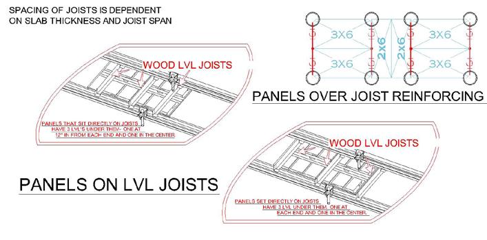
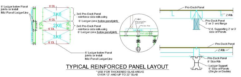
7 SINGLE AND INDEPENDENT POST SHORE SYSTEM SAFETY RULES As Recommended by THE SCAFFOLDING, SHORING AND FORMING INSTITUTE A. ALL INDEPENDENT POST SHORE SYSTEM DECKS SHALL BE LATERALLY STABILIZED by the existing building structure and/or longitudinal, transverse, and diagonal bracing. Bracing shall be installed as the shores are being erected. B. FOLLOW SUPPLIER/MANUFACTURER S RECOMMENDED DIRECTION if applicable for: a. Location and selection of deck panel type and stringers. b. Type and height of vertical shoring components. c. Starting points of deck layouts. C. PRIOR TO WORKING ON DECKS a. All posts shall be plumb in two directions and adjusted evenly to ensure proper bearing contact. b. Check plumb of post shores just prior to pour. c. Deck shall be laterally stabilized. D. FALL PROTECTION SHALL BE PROVIDED ON ALL OPEN SIDES AND OPENINGS in formwork and slabs as required by applicable code. E. PLAN DECK PANEL LAYOUT TO ENSURE AGAINST INSTABILITY AND UNSUPPORTED CANTILEVERS. Take all necessary precautions to avoid uplift of cantilevered panels during and after construction. Make certain that form panels intended to be cantilevered are tied down to prevent tipping. F. PANELS EXPOSED TO UPLIFTING WIND FORCES SHALL BE LOCKED OR TIED DOWN TO PREVENT PANEL UPLIFT. G. PLAN CONCRETE PLACEMENT METHODS AND SEQUENCES TO ENSURE BALANCED LOADING of shoring equipment and panels, including cantilevered panels. H. BRACING SHALL BE FASTENED SECURELY. Check to see that clamps, screws, pins and all other components are in a closed or engaged position. I. ALL VERTICAL AND HORIZONTAL SHORING should be installed and used in compliance with safety rules and recommendations published by The Scaffolding, Shoring and Forming Institute. Erect Ledgers, LVL s and Panels from below. Never erect components while standing on previously erected deck. J. DO NOT INTERMINGLE DAYTON SUPERIOR supplied components with those of other suppliers. K. LATERAL BRACING FOR SINGLE POST SHORES in job-built filler areas must be designed and installed by contractor. L. CONTRACTOR TO PROVIDE SOLID WEDGING under all post shores bearing on or supporting a sloping slab. M. INSURE THAT ALL LVL JOISTS AND PRO-SHORE PANELS are properly in the ledger grooves. N. WHEN CANTILEVERING LEDGERS, LVL JOISTS OR PRO-SHORE PANELS secure opposite end cantilevered component to prevent tipping. 4
8 O. CHECK ALL LOAD PINS FOR FULL BEARING AND SECURE EACH load pin with cotter pin. P. PRO-SHORE DECKS ARE NOT INTENDED TO BE USED as a scaffold work platform. Q. DO NOT USE PRO-SHORE POSTS MORE THAN ONE TIER HIGH. Where greater shore heights are required consult the Dayton Superior Engineering Department. R. PRO-SHORE POSTS WILL REQUIRE ADDITIONAL BRACING when shoring or bearing on sloping slabs. Contact the Dayton Superior Engineering Department for guidance with the bracing requirements. S. DRAWINGS ARE ILLUSTRATIVE ONLY. Specification of products and equipment shown herein are subject to change without notice. 5
9 GENERAL SHORING NOTES 1. Contractor to check and verify all dimensions at job before proceeding with work. 2. Deviation from these layouts may be made only under the direction and supervision of a qualified person who by possession of a recognized degree, certificate, or professional standing, or who by extensive knowledge, training, and experience has successfully demonstrated the ability to solve or resolve problems relating to the subject matter, the work, or the project and/or with the consultation of Dayton Superior Corporation. 3. The shoring installation must comply with safe practice and with the requirements of governmental regulations, codes and ordinances. 4. Contractor shall design and provide suitable sills to properly distribute the imposed shoring loads. 5. When setting elevations, allow for compression of lumber and soil. 6. The design and construction of lumber in job-built filler areas, and formwork, is the responsibility of the contractor. 7. The formwork system must be stabilized to poured columns and walls. The layout as shown is designed with the provision that the framework system is restrained from lateral movement with respect to shoring. The contractor shall provide sufficient lateral support as necessary. 8. The shoring layout is not designed for motorized concrete placing equipment unless specifically stated. 9. The reshoring and backshoring procedures are the responsibility of others, and should be approved by the architect/engineer of record. 10. All vertical and horizontal shoring should be installed and used in compliance with safety rules and recommendations published by The Scaffolding, Shoring & Forming Institute, Inc. and those of Dayton Superior Corporation. Erect ledgers, LVL s & panels from below. Never erect components while standing on previously erected deck. 11. Do not intermingle Dayton Superior Corporation supplied components with those of other suppliers. 12. Lateral bracing for single post shores in job-built filler areas must be designed and installed by a contractor. 13. All vertical shoring equipment shall be plumb in two directions unless otherwise specified on the shoring drawings. 14. Contractor to provide solid wedging under all post shores bearing on or supporting a sloping slab. 15. Follow all additional information shown on General Note Sheet and typical sheets of the shoring layout drawings. In the event a layout drawing is not available or job site conditions change contact Dayton Superior s Engineering Department. 16. Insure that all LVL Joists and Pro-Shore Panels are seated properly in ledger groves. 17. When cantilevering ledgers, LVL Joints or Pro-Shore Panels secure opposite end of cantilevered component to prevent tipping. 18. Check all load pins for full bearing and secure each load pin with a cotter pin. 6
10 19. Prior to pouring concrete, check all star nuts to assure they are tight and snug against bearing plates. 20. Pro-Shore panels are not intended to be used as a scaffold work platform. 21. Do not use Pro-Shore posts more than one tier high. Where greater shore heights are required consult Dayton Superior s Engineering Department. 22. Pro-Shore posts will require additional bracing when shoring or bearing on sloping slabs. Contact Dayton Superior s Engineering for guidance with the bracing requirements. 23. Drawings are illustrative only. Specification of products and equipment shown herein are subject to change without notice. 24. Report any damaged Pro-Shore equipment to Dayton Superior for further instructions. This may include but is not limited to J-catches, panel siderails, dropheads, etc. STABILITY AND LATERAL FORCE CONSIDERATION ON SHORING SYSTEMS Stability Bracing is required during the erection and dismantling of the shoring system when it is freestanding without blocking to a permanent structure. The Pro-Shore Cross-Braces shown on the shoring drawings illustrate a typical method used for stability bracing. The Cross-Braces acting in conjunction with the Ledger and LVL connections at the top of the post shores provide additional stability in the longitudinal and traverse directions. In addition to the standard Pro-Shore Cross-Bracing, all shoring heights in excess of 12-0 may require added bracing. Lateral Bracing is required to resist the horizontal forces acting on the shoring system, such as wind loads, concrete pressures against bulkheads or sloping soffits and dynamic loads during concrete placement. Blocking the plywood and components of the shoring system to the permanent structure provides lateral bracing. The cross braces used as stability bracing may also provide lateral bracing when it is not possible to provide blocking to the structure. A qualified person should analyze every shoring system to determine what lateral bracing is required. Contact Dayton Superior Engineering for assistance. 7
11 BASIC EQUIPMENT Post Shores The selection of shores in the Pro-Shore system offers the largest range of heights in the industry: 6-8 to 21-0 ¾. The single posts allow for a clean, unbraced area for material movement and easy access. All posts have eight (8) locations for Jet-Lok attachment. This expands the flexibility of the system when Cross-Braces are required to produce 4-legged towers for safe erection of the system. No tripods or wood bracing is required. The Posts have a 3.0:1 Factor of Safety while supplying safe support for slabs up to 18 in depth. P/C Description Weight F57073 Primary Post 58 lbs F Extension 15 lbs F57075 #3 Post Shore 43 lbs Universal Drophead The Universal Drophead is a key component of the Pro-Shore System. The drophead facilitates the stripping process, allowing the LVL s (or Panels), Ledgers, and plywood to be stripped and moved forward to the next pour while maintaining a shore in place for structural support. P/C Description Weight F57079 Universal Drophead 15 lbs F57082 ¾ x 4 Bolt 1 lbs Notes: Add 2 to minimum dimension for stripping. Only use one (1) 2 Extension per shore. Ensure all load pins are secured with cotter pins. Refer to page 33 for minimum and maximum shoring heights using the Drophead. 8
12 Ledgers Ledgers are utilized as the main stringers of the Pro-Shore System. They span from one Drophead to the next. The end catch at each end of the aluminum Ledger sets and locks into the catch plate on the Dropheads of adjacent shores. The Ledgers also have a catch on both sides which runs the length of the Ledger to receive LVL s or Pro-Deck Panels. The profile on the bottom of the Ledgers allows accessories to be attached for different support applications. Pro-Shore Ledgers are color-coded and match colors on Dayton Superior Engineered drawings for ease of use and assembly on the job site. P/C Description Weight F Ledger Red 40 lbs F Ledger Green 53 lbs F Ledger Silver 67 lbs P/C Actual Length Length L F / F / F / LVL Joists with End Catches LVL s are used as the joists of the Pro-Shore System. They are lightweight and span from Ledger to Ledger. The end catch at each end of the joist sets and locks into the catch plate of parallel Ledgers. Since Ledgers have catch plates running their full lengths, LVL s can be placed at virtually any spacing to accommodate different slab thicknesses or job site conditions. Contractor-supplied plywood is placed on top of the LVL s. Pro-Shore LVL s are color-coded and match colors on Dayton Superior Engineered drawings. P/C Description Weight F LVL Joist Black 14 lbs F LVL Joist Blue 15 lbs F LVL Joist Red 18 lbs F Aluminum Joist Orange 18 lbs P/C Actual Length Length L F ¼ 4-0 F ¼ 5-0 F ¼ 6-0 F /
13 Cross-Bracing The Cross-Braces with the Pro-Shore System provide stability to safely begin the erection sequence. They are also used in cantilever conditions, adding stability to the local shores. Pro-Shore Cross-Braces are color-coded and match colors on Dayton Superior Engineered drawings for ease of use and assembly on the job site. P/C Description Weight F x 8 Cross-Brace 12 lbs F x 6 Cross-Brace 10 lbs F x 5 Cross-Brace 9 lbs F x 4 Cross-Brace 8 lbs P/C Cross-Brace C/C Dimension F x F x F x F x Panels Pro-Deck utilizes two standard, modular panel sizes. These panels are a powder-coated 4 ¼ deep frame with a ½ thick plywood deck pre-cut and placed inside the frame. P/C Description Weight F x 6-0 Panel 46 lbs F x 6-0 Panel 18 lbs Wood Replacement F x 6-0 Panel 63 lbs 10
14 KEY ACCESSORIES Clips The Pro-Shore system can incorporate a set of different clips to safely and efficiently accommodate various jobsite specific applications. P/C Description Weight F57068 Ledger to Drophead Clip 0.5 lbs F57069 Ledger to Hold Down Clip 0.5 lbs F57070 Ledger to Ledger Clip 0.5 lbs Guardrail Post w/twistlock P/C F lbs The Guardrail Post can be attached to Ledgers and offers a safe connection for contractor-supplied safety railing. It is connected to Ledgers using a Twistlock; see page 15. The Toeboard Support also features adjustability to slide up or down to accommodate different deck material. Bracing Slider w/two Jet-Loks P/C F lbs The Bracing Slider is used to facilitate the use of Cross-Bracing in sloped slab conditions. It is attached at Jet-Lok locations of adjacent post shores. See page 32 for details. 11
15 Ledger Hanger P/C F lbs Ledger Hangers can be used to hang a Ledger below the main grid Ledgers, providing a lower deck for drop heads or drop beams. See page 21 for details. PRO-SHORE ERECTION SEQUENCE 1. Prior to erecting Pro-Shore Posts, ensure the bearing plate is in the up position and the star nut is tight: a. Raise the lower bearing plate of the Drophead to the stop position b. Raise the star nut to the underside of the lower plate c. Hammer the star nut in the clockwise direction to secure the bearing plate 2. The first step of erecting the Pro-Shore system is setting up a fully braced tower using four (4) posts and Cross-Braces. This creates a stable base from which to hang Ledgers and LVL s. The starting position should be shown on the drawing in a location that is easy to set out from field measurements and structural elements. 3. Place one end of the Ledger into the Pro-Shore Drophead assembly. 4. Raise the opposite end of the Ledger and place it into the second Pro-Shore Drophead assembly. 5. Repeat steps 3 & 4 to erect a parallel Ledger in the remaining two Pro-Shore posts. 12

16 6. Place one (1) LVL into the bottom slot of the Ledger near the first pair of erected Pro-Shore posts and raise it up to the adjacent Ledger. 7. Erect additional LVL s at the spacing shown on the Dayton Superior layout drawing. 8. Continue erecting Ledgers by placing one end of the Ledger into a previously erected Pro-Shore Drophead assembly and raising the other end of the Ledger, using another Pro-Shore post as a prop. 9. Add an LVL between each subsequent erected pair of post shores to provide additional stability. 10. It is recommended a brace tower of four (4) Pro-Shore posts be erected with a maximum of six (6) bays between the braced towers in either direction during erection and dismantling. 11. When it is necessary to cantilever a Ledger over a Pro-Shore post, a plastic spud is inserted into the bottom the slot of the string and tightened. The post can then be erected and the plastic spud inserted into the hole of the Drophead plate. 13
17 12. When it is necessary to cantilever a Ledger over and beyond a Drophead, follow these steps: a. Secure the Ledger to the Drophead with two (2) Ledger Hold Down Clips. b. Additional Cross-Bracing may be required at cantilevered conditions next to interior openings, walls, beam sides, and other similar applications. 13. When it is necessary to cantilever a Ledger beyond a slab edge, follow these steps: a. Attach a Ledger Hold Down Clip to the underside of the cantilevered Ledger and bear under the star nut of a Drophead plate. b. Always brace the exterior Pro-Shore posts to the adjacent posts in two directions using Cross-Braces 14
18 PRO-SHORE PERIMETER GUARDRAIL ATTACHMENT PROCEDURES 15
19 PRO-SHORE PANEL ERECTION SEQUENCE 1. From below, place one end of the Pro-Shore panel on a previously erected and stabilized Ledger. To ensure a proper Ledger set-up, please follow steps 1-5 on page 12 of this Application Guide. 2. Rotate the unsupported end of the Pro-Shore panel above the adjacent stabilized Ledger. 3. Slide the Pro-Shore panel over the second Ledger until the J-Catch of the panel locks into the first Ledger. 4. Lower the Pro-Shore panel, ensuring the J-Catch locks into place in the second Ledger. 16
20 5. To complete placement of the last Pro-Shore panel in a bay, lift the adjacent panel and last panel and lower both panels together. 6. Repeat the previous steps to erect the remaining Pro-Shore panels. 7. When it is necessary to cantilever a Ledger beyond a slab edge, follow these steps: a. Attach a Ledger to Drop Head Clip to the underside of the cantilevered Ledger and bear under the star nut of the drop head plate. b. Always brace the exterior Pro-Shore posts to the adjacent posts in two directions using Cross-Braces. 17
21 PRO-SHORE STRIPPING SEQUENCE Notes: Reshores and backshores as defined below are some of the most critical operations in formwork; consequently, the reshoring and backshoring shall be designed by a qualified person and should be approved by the architect/engineer of record. Reshores: Shores placed snugly under a stripped concrete slap or structural member after the original forms and shoring have been removed from a large area, thus requiring the new slab or structural member to deflect and support its own weight and existing construction loads applied prior to the installation of reshores. Backshores: Shores placed snugly under a concrete slab or structural member after the original formwork and shores have been removed from a small area at a time, without allowing the slab or member to deflect, thus the slab or other members does not yet support its own weight or exiting construction loads from above. 1. Begin by hammering the star nut in a counterclockwise direction in a three (3) bay wide area. This will drop all Ledgers and LVL s approximately 2 ½ while leaving the plywood pinched between the Dropheads and concrete slab soffit. 2. Remove the LVL s and stack onto a cart while carefully removing any loose plywood and stacking for reuse. 3. Lower the Ledgers and place them onto a second cart. 4. Once concrete has gained sufficient strength, lower the Pro-Shore posts to remove any remaining plywood. Reset the posts for use and reshore if required. 18

22 PRO-SHORE PANEL STRIPPING SEQUENCE 1. Begin by hammering the star nut in a counterclockwise direction in a three (3) bay wide area. This will drop all Ledgers and Panels approximately Release the star nut on several posts in adjacent rows to lower the Panel drop heads. 19
23 3. Raise the Panel up and slide over adjacent Ledger and Panel. Finally, lower the Panel. 4. Continue lowering subsequent Panels and stack on cart for movement to the next pour. 20

24 PRO-SHORE TYPICAL APPLICATION DETAILS Slab Conditions and Thicknesses Note: Contractor to ensure proper fall protection is provided on all open sides and openings in formwork and slabs as required by local and applicable codes. 21
25 Column Conditions Note: Contractor to ensure proper fall protection is provided on all open sides and openings in formwork and slabs as required by local and applicable codes. 22
26 Cantilevered Conditions Note: Contractor to ensure proper fall protection is provided on all open sides and openings in formwork and slabs as required by local and applicable codes. 23
27 Note: Contractor to ensure proper fall protection is provided on all open sides and openings in formwork and slabs as required by local and applicable codes. 24
28 Corner Conditions Note: Contractor to ensure proper fall protection is provided on all open sides and openings in formwork and slabs as required by local and applicable codes. 25
29 Note: Contractor to ensure proper fall protection is provided on all open sides and openings in formwork and slabs as required by local and applicable codes. 26

30 PRO-SHORE PANEL TYPICAL APPLICATION DETAILS Slab Conditions and Thicknesses Column Conditions Note: Contractor to ensure proper fall protection is provided on all open sides and openings in formwork and slabs as required by local and applicable codes. 27
31 Note: Contractor to ensure proper fall protection is provided on all open sides and openings in formwork and slabs as required by local and applicable codes. 28
32 Note: Contractor to ensure proper fall protection is provided on all open sides and openings in formwork and slabs as required by local and applicable codes. 29
33 Other Considerations 30
34 SLOPED SLABS When it is necessary to place Pro-Shore on sloped surfaces additional bracing and analysis is required. If slopes are greater than 12%, contact the Dayton Superior Engineering Department. The drawings below are for illustrative purposes only, each case is different. Note: Contractor to ensure proper fall protection is provided on all open sides and openings in formwork and slabs as required by local and applicable codes. 31

35 BRACING SLIDER To facilitate proper Cross-Bracing of Pro-Shore bearing on a sloped slab, the Brace Slider is attached to one or both of the posts. The Bracing Slider is attached at the Jet-Lock locations of the post shores. The Cross-Braces are then attached to the Brace Slider and pivoted into position to the adjacent post shore. Note: Contractor to ensure proper fall protection is provided on all open sides and openings in formwork and slabs as required by local and applicable codes. 32
36 MINIMUM & MAXIMUM SHORE HEIGHTS P/C Post Fully Closed Height Universal Drophead (Lowered) Universal Drophead (Raised) F57073 Primary Post N/A Primary Post w/2 Extension F57075 #3 Post Shore

37 Dayton Superior products are intended for use by trained, qualified and experienced workmen only. Misuse or lack of supervision and/or inspection can contribute to serious accidents or deaths. Any application other than those shown in this publication should be carefully tested before use. The user of Dayton Superior products must evaluate the product application, determine the safe working load and control all field conditions to prevent applications of loads in excess of a product s safe working load. Safety factors shown in this publication are approximate minimum values. The data used to develop safe working loads for products displayed in this publication are a combination of actual testing and/or other industry sources. Recommended safe working loads given for the products in this publication must never be exceeded. Worn Working Parts For safety, concrete accessories must be properly used and maintained. Concrete accessories shown in this publication may be subject to wear, overloading, corrosion, deformation, intentional alteration and other factors that may affect the device s performance. All reusable accessories must be inspected regularly by the user to determine if they may be used at the rated safe working load or should be removed from service. The frequency of inspections depends upon factors such as (but not limited to) the amount of use, period of service and environment. It is the responsibility of the user to schedule accessory hardware inspections for wear and remove the hardware from service when wear is noted. Shop or Field Modification Welding can compromise a product s safe working load value and cause hazardous situations. Knowledge of materials, heat treating and welding procedures is necessary for proper welding. Consult a local welding supply dealer for assistance in determining required welding procedures. Since Dayton Superior cannot control workmanship or conditions in which modifications are done, Dayton Superior cannot be responsible for any product altered in the field. Interchangeability Many concrete accessory products that Dayton Superior manufactures are designed as part of a system. Dayton Superior strongly discourages efforts to interchange products supplied by other manufacturers with components supplied by Dayton Superior. When used properly, and in accordance with published instructions, Dayton Superior products have proven to be among the best designed and safest in the industry. Used improperly or with incompatible components supplied by other manufacturers, Dayton Superior products or systems may be rendered unsafe. Installation WARNING 1. Dayton Superior Corporation products shall be installed and used only as indicated on the Dayton Superior Corporation installation guidelines and training materials. 2. Dayton Superior Corporation products must never be used for a purpose other than the purpose for which they were designed or in a manner that exceeds specific load ratings. 3. All instructions are to be completely followed to ensure proper and safe installation and performance. 4. Any improper misuse, misapplication, installation, or other failure to follow Dayton Superior Corporation s instruction may cause product malfunction, property damage, serious bodily injury and death. THE CUSTOMER IS RESPONSIBLE FOR THE FOLLOWING: 1. Conformance to all governing codes 2. Use of appropriate industry standard hardware 3. The integrity of structures to which the products are attached, including their capability to safely accept the loads imposed, as evaluated by a qualified engineer. SAFETY INSTRUCTIONS: All governing codes and regulations and those required by the job site must be observed. Always use appropriate safety equipment. Design Changes Dayton Superior reserves the right to change product designs, rated loads and product dimensions at any time without prior notice. Note: See Safety Notes and Safety Factor Information.

38 1125 Byers Road Miamisburg, OH PERFORM WITH PRECISION Copyright 2015 Dayton Superior Corporation, All Rights Reserved.
Table of Contents Big expertise. Real convenience. Concrete commitment.
 Table of Contents General Shoring Safety Rules As Recommended By The Scaffolding, Shoring And Forming Institute... 1 General Guidelines... 1 Single And Independent Post Shore System Safety Rules As Recommended
GSSIM. Mini Scaffold (Interior or Exterior) Assembly & Operating Instructions
 Assembly & Operating Instructions") GSSIM Mini Scaffold (Interior or Exterior) Assembly & Operating Instructions READ ALL INSTRUCTIONS AND WARNINGS BEFORE USING THIS PRODUCT. This manual provides important information on proper operation
GSSIM Mini Scaffold (Interior or Exterior) Assembly & Operating Instructions READ ALL INSTRUCTIONS AND WARNINGS BEFORE USING THIS PRODUCT. This manual provides important information on proper operation
PRO-SHORE. Shoring Systems
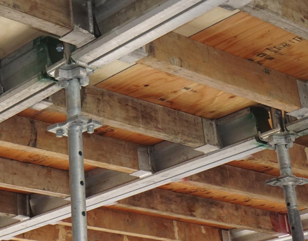
 Shoring Systems Features and Benefits The new Pro-Shore Shoring System consists of special drophead post shores, aluminum ledgers (mains), and laminated wood joists (secondaries) or panels. This system
AR SCAFFOLDING AR ALUMINUM MOBILE AR STEEL MOBILE
 SAFETY RULES and INSTRUCTIONS FOR AR SCAFFOLDING AR ALUMINUM MOBILE AR STEEL MOBILE INTERIOR or EXTERIOR USE ! WARNING! Improper assembly, dismantling or use of Multi-Use Scaffold may result in serious
SafeDeck Supported Scaffold System
 SafeDeck Supported Scaffold System Table of Contents Origination 1 Range of Motion 1 Installation Efficiency 2 Third-Party Testimonial 2 SafeDeck Specifications 3 Competent Person 4 Tools Required 4 Components
Multi-Purpose Scaffolding Instruction Manual
 Limited Warranty World Factory, Inc. World Factory, Inc. (Seller) warrants to the original Buyer only, that each YellowStone Product will be free from defects in material and workmanship for a period of
Pro-Shore LLC MODULAR DECK SYSTEM. The
 Pro-Shore LLC MODULAR DECK SYSTEM The Pro-Shore @dvantage Product flexibility - 5'-10"to 21'-0 ¾" single post capacity Up to 18 slabs can be supported with standard equipment Lower freight costs - 5000
PERFORM WITH PRECISION BOX CULVERT TRAVELER CONCRETE CONSTRUCTION PRODUCTS APPLICATION GUIDE
 PERFORM WITH PRECISION BOX CULVERT TRAVELER CONCRETE CONSTRUCTION PRODUCTS APPLICATION GUIDE A WORD ABOUT SAFETY High productivity depends on safety; even a minor accident causes job delays and inefficiency,
ALISPLY. Scaffold Plank. Aligner. Plate Washer ½ x 6 x 6
 Alisply components and accessories illustrated herein have been designed with safety and performance in mind to help achieve a safe and productive forming operation. It is recommended that all construction
Shore X. Higher Capacity And Unique Extension Frames Can Cut Costs. Shore X. Heavy Duty Shoring
 Shore X Heavy Duty Shoring Shore X Higher Capacity And Unique Extension Frames Can Cut Costs > fewer towers needed < fewer types and sizes of components needed > reduced erection costs < lowered stripping
Interior Hangers. Application
 Application Interior bridge deck hangers are typically fabricated using two heavy duty sheet metal end clips that have been electrically resistance welded to an appropriate sized wire or formed metal connecting
Safety Documents > Safety Manual > Scaffolds
 Safety Documents > Safety Manual > Scaffolds D. Scaffolds 1. General Requirements for All Scaffolds a. Scaffolds shall be furnished and erected in accordance with this standard for persons engaged in work
ASSEMBLY.
 ASSEMBLY www.proscaf.com ASSEMBLY SECTION Points to Consider These assembly instructions are generic and may not apply to all applications. If you have questions regarding specific applications contact
BUILDING STRENGTH GUIDELINES FOR HANDLING PRECAST CONCRETE PIPE AND UTILITY PRODUCTS CONCRETE CONSTRUCTION PRODUCTS
 BUILDING STRENGTH GUIDELINES FOR HNDLING PRECST CONCRETE PIPE ND UTILITY PRODUCTS CONCRETE CONSTRUCTION PRODUCTS Table of Contents Safety Factors... 1 P50 SL Universal Lifting Eye... 2 Inspection and Maintenance...
Sectional Scaffold. Scaffold Access Unit Installation Instructions
 Sectional Scaffold Scaffold Access Unit Installation Instructions 2 Scaffold Access Unit Installation Instructions SAU6 Painted: 18.3 lb Galvanized: 20.2 lb Label 7112A0003 NOTICE Please read and follow
Systems Scaffold Tubular Scaffold Access Unit Installation Instructions
 Systems Scaffold Tubular Scaffold Access Unit Installation Instructions 2 Tubular Scaffold Access Unit Installation Instructions LTUB7 Galvanized: 24.1 lb Label 7112A0003 NOTICE Please read and follow
Method Statement Concrete Support Systems
 Method Statement Method Statement Concrete Support Systems Introduction Concrete Support Systems is renowned as one of the leading manufacturers and suppliers of equipment to the construction and civil
Standards for Testing and Rating Shoring Equipment
 ANSI/SSFI SH300-2007 American National Standard Standards for Testing and Rating Shoring Equipment Scaffolding, Shoring & Forming Institute, Inc. Sponsor: Scaffolding, Shoring & Forming Institute, Inc.
STANDARD PRACTICE INSTRUCTION
 STANDARD PRACTICE INSTRUCTION DATE: March 1, 2001 SUBJECT: Scaffolding Safety Program. REGULATORY STANDARDS: 29 CFR 1910.28 Safety Requirements For Scaffolding. 29 CFR 1910.29 Manually Propelled Mobile
P: F: Resi-Ply FORMING SYSTEM BY DAYTON SUPERIOR
 Resi-Ply FORMING SYSTEM BY DAYTON SUPERIOR Resi-Ply System The Resi-Ply forming system is a 1 1 thick plywood with steel backing bars designed especially for residential foundations and low industrial
DIVISION 03 CONCRETE SPECIFICATION : FORMS AND FORMWORK
 DIVISION 03 CONCRETE SPECIFICATION 031000: FORMS AND FORMWORK PART 1.0 GENERAL 1.1 DESCRIPTION The work of this specification includes furnishing of all labor, materials, equipment and incidentals to install,
Universal Panels & Accessories
 Universal Panels & Accessories Erection Procedures INTRODUCTION Use common sense when working with Scaffold Your Safety is our #1 Concern Universal Scaffolds are designed with your safety in mind every
SECTION CONCRETE FORMWORK AND ACCESSORIES
 SECTION 03100 CONCRETE FORMWORK AND ACCESSORIES Part 1 GENERAL 1.01 SUMMARY A. Furnish equipment, materials, and labor required for construction and removal of forms for the containment of concrete to
TECHNICAL SPECIFICATION
 TECHNICAL SPECIFICATION ITEM 03100 CONCRETE FORMWORK 1.0 GENERAL 1.1 DESCRIPTION This section defines requirements and limitations for design, construction, erection, and removal of concrete formwork for
Reliant Holdings Ltd Safety Management System
 Preparation: Safety Mgr Authority: President Issuing Dept: Safety Page: Page 1 of 7 Purpose The purpose of this program is to prevent injuries due to falls from elevated work areas and ensure employees
OSHA Rules for Scaffolding
 OSHA Rules for Scaffolding A) Objectives: 1. 2. 3. Don t let the scaffold fall. Don t fall off the scaffold. Don t let the material fall off the scaffold. Name of Competent Person: Name of Qualified Person:
WARNING SAFETY RULES AND INSTRUCTIONS FOR BIL-JAX UTILITY SCAFFOLD
 WARNING SAFETY RULES AND INSTRUCTIONS FOR BIL-JAX UTILITY SCAFFOLD Any piece of equipment can be dangerous if not operated properly. YOU are responsible for the safe operation of this equipment. The operator
Smarter. Safer. Leaner.
 Smarter. Safer. Leaner. Fast Installation and Removal Decrease Leading Edge Exposure by 87% OSHA Compliant Versatile and Reusable Use Perimeter Protection Posts During Construction: At Building Perimeter
SECTION ELEVATED BLEACHERS (Angle Frame Semi-Closed Deck)
") SECTION 13125 ELEVATED BLEACHERS (Angle Frame Semi-Closed Deck) PART 1 GENERAL 1.1 RELATED DOCUMENTS A. Drawings and general provisions of the Contract, including General and Supplementary Conditions and
SECTION 13125 ELEVATED BLEACHERS (Angle Frame Semi-Closed Deck) PART 1 GENERAL 1.1 RELATED DOCUMENTS A. Drawings and general provisions of the Contract, including General and Supplementary Conditions and
SCAFFOLD COUNT AND MESSAGE SHEET
 SCAFFOLD COUNT AND MESSAGE SHEET COUNTRACT #... NOTE: OUTRIGGERS ARE REQUIRED WHEN HEIGHT MORE THAN 3 TIMES BASE WIDTH ITEM DESCRIPTION QUANTITY OUT CUST. INITIAL QUANTITY IN CUST. INITIAL INTERIOR END
Metal Scaffolds. (1) Metal scaffolds shall be designed to support all dead, live, and wind loads to which they will be subjected.
 Metal scaffolds shall be designed to support all dead, live, and wind loads to which they will be subjected.") Metal Scaffolds 1644 May 2016 (a) General. (1) Metal scaffolds shall be designed to support all dead, live, and wind loads to which they will be subjected. (2) No metal scaffold equipment that is broken
Metal Scaffolds 1644 May 2016 (a) General. (1) Metal scaffolds shall be designed to support all dead, live, and wind loads to which they will be subjected. (2) No metal scaffold equipment that is broken
FrameFast Shoring System
 FrameFast FrameFast Shoring System The FrameFast shoring system is engineered for maximum strength, labor productivity and reuse capabilities. FrameFast components feature high strengthto-weight ratios.
BoSS Climalite Camera and lighting tower
 Contents Safety First Safety First Quantity Schedules Toeboard 2 9 13 33 INTRODUCTION Please read this guide carefully. Please note that diagrams are for illustrative purposes only. User guides are also
DEPAUL UNIVERSITY. Scaffolding Program. Environmental Health & Safety. April 2017
 DEPAUL UNIVERSITY Scaffolding Program Environmental Health & Safety April 2017 1 TABLE OF CONTENTS SECTION PAGE NO. 1.0 PURPOSE 2 2.0 SCOPE 2 3.0 SCAFFOLDING ERECTOR 2 4.0 GENERAL 2 5.0 WOOD SCAFFOLDING
USER S MANUAL HAKI PUBLIC ACCESS STAIR
 USER S MANUAL HAKI PUBLIC ACCESS STAIR HAKI AB 2018 Important information HAKI s product liability and user s manuals apply only to scaffolds that are entirely composed of components that have been made
The original WACO RED premium frame scaffolding and shoring systems.
 The original WACO RED premium frame scaffolding and shoring systems. 2 WACO Premium Frame Scaffolding and Shoring System Used by thousands of the industry s top contractors and professionals, Waco Red
CIRCULAR COLUMN SK 100
 CIRCULAR COLUMN SK 100 www.variant-factory.eu 1 2 VARIANT FACTORY LTD. CIRCULAR COLUMN SK 100 Contents GENERAL INSTRUCTIONS.....................................................................................
Big Ox Energy Siouxland, LLC. Safety Management System. Authority: President
 Issuing Dept: Safety Page: Page 1 of 5 Purpose The purpose of this program is to provide guidelines to Big Ox Energy - Siouxland LLC employees in the safe use of scaffolding, and to reduce the risk of
TCC/SHORE TRANSIT BUS MAINTENANCE FACILITY - PHASE II
 SECTION 052100 - STEEL JOISTS PART 1 - GENERAL 1.1 RELATED DOCUMENTS: A. Drawings and General Provisions of the Contract, including General and Supplementary Conditions and Division 1 Specification Sections
Alternate Formwork System Evaluation
 Alternate Formwork System Evaluation Executive Summary The current handset aluminum formwork system used in the Navy League Building s parking garage is a labor and material (plywood) intensive process.
Y SIDE ALUMINUM TRUCK RACK
 Y SIDE ALUMINUM TRUCK RACK Owner s Manual WARNING: Read carefully and understand all ASSEMBLY AND OPERATION INSTRUCTIONS before operating. Failure to follow the safety rules and other basic safety precautions
Typical Deck Details Based on the 2009 International Residential Code (Designed and Printed August 2010)
") 1307 West Lehigh Street Bethlehem, PA 18018 610-866-9663 Office info@keycodes.net www.keycodes.net Typical Deck Details Based on the 2009 International Residential Code (Designed and Printed August 2010)
1307 West Lehigh Street Bethlehem, PA 18018 610-866-9663 Office info@keycodes.net www.keycodes.net Typical Deck Details Based on the 2009 International Residential Code (Designed and Printed August 2010)
Supported Scaffold Inspections
 Supported Scaffold Inspections May 2016 Inspect scaffolds and scaffold parts daily, before each work shift, and after any event that may have caused damage. Check to see if power lines near scaffolds are
Scaffolding Procedures
 Procedures Purpose It is the purpose of this company in issuing these procedures to further ensure a safe workplace based on the following formal, written procedures for scaffold work. Application This
SECTION PLATE CONNECTED WOOD TRUSSES
 SECTION 06173 PLATE CONNECTED WOOD TRUSSES PART 1 GENERAL 1.01 SUMMARY A. Section Includes: 1. Shop fabricated wood trusses for roof and floor framing. 2. Bridging, bracing, and anchorage. B. Related Sections:
PORTABLE LADDER SAFETY
 LADDER AND SCAFFOLD SAFETY PLAN Ladder & Scaffold Safety Falls can result in serious injury or death. Falls from a higher elevation account for approximately 10% of workplace fatalities and 5.2% of nonfatal
DIVISION 5 - STRUCTURAL STEEL AND IRON WORK
 DIVISION 5 - STRUCTURAL STEEL AND IRON WORK SECTION 05100 STRUCTURAL METAL FRAMING PART 1.00 GENERAL 1.01 SCOPE OF WORK A. Work Included: 1. 2. Structural steel complete in place. Steel joists complete
USER S MANUAL HAKI PUBLIC ACCESS STAIR
 USER S MANUAL HAKI PUBLIC ACCESS STAIR HAKI AB 2017 Important information HAKI s product liability and user s manuals apply only to scaffolds that are entirely composed of components that have been made
SPECIFICATION FOR PERMANENT BEAM GRANDSTAND WITH INTERLOCK WELDED DECK SYSTEM
 E & D SPECIALTY STANDS, INC. MANUFACTURERS OF QUALITY STANDS AND SEATING 2081 FRANKLIN STREET - P.O. BOX 700 - NORTH COLLINS, NEW YORK 14111 716-337-0161-1-800-525-8515 FAX 716-337-2903 - SALES FAX 716-337-3436
HILLSBOROUGH TOWNSHIP CODE ENFORCEMENT
 HILLSBOROUGH TOWNSHIP CODE ENFORCEMENT SAMPLE GUIDE FOR RESIDENTIAL DECKS revised 7 16 Call before you dig! 1 800 272 1000 New Jersey One Call. Utility Mark Out. THIS GENERIC GUIDE IS NOT ALL INCLUSIVE
OSHA Rules for Scaffolding
 OSHA Rules for Scaffolding A) Objectives: 1. 2. 3. Don t let the scaffold fall. Don t fall off the scaffold. Don t let the material fall off the scaffold. Name of Competent Person: Name of Qualified Person:
Shoring and Reshoring Fundamentals
 Shoring and Reshoring Fundamentals by Mary Bordner Tanck, PE SHORING AND RESHORING FUNDAMENTALS Because it has such a significant impact on schedule and material movements, it is important for everyone
DIVISION 5 METALS SECTION METAL DECKING
 DIVISION 5 METALS SECTION 05 30 00 PART 1 GENERAL 1.01 SUMMARY A. Section Includes: All labor and materials required to furnish and install metal decking and accessories including shear connectors, closures,
LOGIK. Forming System
 LOGIK Forming System LOGIK Wall formwork crane-handled Description The Logik panel system for crane handling, produces up to 1670 psf concrete pressure resistance from a strong panel. The panel frames
General and Technical Information
 Safety Notes and Product Application Dayton Superior strives to ensure that all products supplied from its manufacturing plants meet or exceed the safety requirements inherent in the proper use of its
Citations in brackets are from Title 8 of the California Administrative Code.
 SAFETY WALKAROUND CHECKLIST SCAFFOLDS 2001 Date Prepared: Project Name/No: By: Location: Check the box if the statement is true. Fill in the blanks where the appears. Citations in brackets are from Title
PERI UP Easy * The lightweight and fast frame scaffold for safe working on facades
 PERI UP Easy * The lightweight and fast frame scaffold for safe working on facades Product Brochure * If approval is required for the scaffolding system PERI UP Easy to be placed on the market in a country,
FACT SHEET #2 DECK INFORMATION
 Borough of Doylestown Building and Zoning Department 57 West Court Street, Doylestown, PA 18901 215.345.4140 FACT SHEET #2 DECK INFORMATION BACKGROUND The provisions of the PAUCC. ICC Property Maintenance
CONCRETE FORMWORK. .2 CSA , Supplement No.1 to CAN/CSA , Engineering Design in Wood. .4 CSA O151, Canadian Softwood Plywood.
 CITY OF BRAMPTON LANDSCAPE SPECIFICATIONS SECTION 03100-1 PART 1 GENERAL 1.1 Related Work.1 All Division 1 Specification Sections.2 Section 02233 Granular Base.3 Section 02311 Site Grading.4 Section 03200
CAL SCAFFOLD USER GUIDELINES COURSE SUMMARY
 CAL SCAFFOLD USER GUIDELINES COURSE SUMMARY The following guide is an aid intended for students who have completed the ClickSafety training course or module associated with Scaffold Safety. This guide
Megashore system. Method statement
 Megashore system Method statement Method statement Megashore system Contents Page Introduction 2 Disclaimer 2 Site safety 3 Your responsibilities 3 Safe working practice 4 Personal protective equipment
General Guidelines. Instructions for Part # WP Safety. It is the user s responsibility to read and follow all instructions.
 General Guidelines It is the user s responsibility to read and follow all instructions. Instructions for Part # WP-48-1000 Keep these instructions with the product at all times and review before each use.
SECTION MECHANICALLY ASSISTED MOBILE STORAGE SHELVING PART 1 - GENERAL 1.1 RELATED DOCUMENTS
 SECTION 10560 MECHANICALLY ASSISTED MOBILE STORAGE SHELVING PART 1 - GENERAL 1.1 RELATED DOCUMENTS A. Drawings and general provisions of the Contract, including General and Supplementary Conditions and
A. Submit the following within 30 days of award of contract under provisions of Division 1 and according to the Conditions of the Contract:
 SECTION 11060 PORTABLE STAGING SYSTEM PART 1 GENERAL 1.1 SUMMARY A. Section Includes: 1. The fabrication, furnishing, delivery and installation of a of Smartstage Platform System. 2. Training of Owner
117-Bin Wire Shelf Storage Rack
 117-Bin Wire Shelf Storage Rack Owner s Manual WARNING: Read carefully and understand all ASSEMBLY AND OPERATION INSTRUCTIONS before operating. Failure to follow the safety rules and other basic safety
USER S MANUAL HAKI COMPACT STAIR TOWER
 USER S MANUAL HAKI COMPACT STAIR TOWER HAKI AB 2018 Important information HAKI s product liability and user s manuals apply only to scaffolds that are entirely composed of components that have been made
Important: Before You Start
 Advantage ICF System Advantage ICF System TM Field Guide Important: Before You Start Does Your Building Inspector Know You Are Building with the Advantage ICF System? You are required to check with your
Division 03 - Concrete Section New Westminister Multi-Use Civic Facility & Office Building Project No Page 1
 Project No. 210022 Page 1 PART 1 GENERAL 1.7 Documents.1 The General Conditions of the Canadian Standard Construction Document CCDC-2, together with all amendments and supplements and Division 1 General
Aluma EasySet Continuing Innovation from Aluma S ystems
 Product Sheet Aluma EasySet Aluma Systems Concrete Construction Aluma EasySet Continuing Innovation from Aluma S ystems Introduction With more than 35 years of experience in shoring and formwork, Aluma
 Instruction Manual Span Scaffolds! W A R N I N G! Before using Instant UpRight Scaffolds, read, understand and follow all Safety Rules, Erection Instructions and Maintenance Rules. Keep this manual for
RESPONSIBILITIES IN THE DESIGN PROCESS INVOLVING METAL PLATE CONNECTED WOOD TRUSSES
 CHAPTER 2 RESPONSIBILITIES IN THE DESIGN PROCESS INVOLVING METAL PLATE CONNECTED WOOD TRUSSES 2.1 PURPOSE The purpose of this chapter is as follows: 2.1.1 To define and draw attention to the typical duties
VOLUNTARY - EARTHQUAKE HAZARD REDUCTION IN EXISTING HILLSIDE BUILDINGS (Division 94 Added by Ord. No. 171,258, Eff. 8/30/96.)
") DIVISION 94 VOLUNTARY - EARTHQUAKE HAZARD REDUCTION IN EXISTING HILLSIDE BUILDINGS (Division 94 Added by Ord. No. 171,258, Eff. 8/30/96.) SEC. 91.9401. PURPOSE. (Amended by Ord. No. 172,592, Eff. 6/28/99,
DIVISION 94 VOLUNTARY - EARTHQUAKE HAZARD REDUCTION IN EXISTING HILLSIDE BUILDINGS (Division 94 Added by Ord. No. 171,258, Eff. 8/30/96.) SEC. 91.9401. PURPOSE. (Amended by Ord. No. 172,592, Eff. 6/28/99,
Scaffolds. OSHA Office of Training & Education 1
 Scaffolds OSHA Office of Training & Education 1 What Is A Scaffold? An elevated, temporary work platform Three basic types: Supported scaffolds -- platforms supported by rigid, load bearing members, such
Panel Jack Pro System BRACING, ALIGNMENT AND SCAFFOLDING EQUIPMENT
 IMPORTANT SAFETY INFORMATION FOR USERS OF THE REECHCRAFT, BRACING SYSTEM PLEASE READ BEFORE USE Panel Jack Pro System BRACING, ALIGNMENT AND SCAFFOLDING EQUIPMENT UK Edition 1.3 26/11/2012 1 TABLE OF CONTENTS
Instruction Manual Span Scaffolds
 Instruction Manual Span Scaffolds QUALITY & STRENGTH YOU CAN TRUST! W A R N I N G! Before using Instant UpRight Scaffolds, read, understand and follow all Safety Rules, Erection Instructions and Maintenance
3T - Through The Trapdoor Method
 ALTO MEDIUM DUTY STAIRWELL TOWER Aluminium Access Tower ISSUE 3 Instruction Manual EN 1298-IM-EN The ALTO MD Stairwell Tower 3T - Through The Trapdoor Method Lakeside Industries Ltd www.altoaccess.com
Rolling Towers. Layher Rolling Towers Uni Wide. Safety Structure Instructions for Assembly and Use. Mobile working platforms to DIN EN 1004:
 Layher Rolling Towers Uni Wide Safety Structure Instructions for Assembly and Use Mobile working platforms to DIN EN 1004:2005-03 Working platform 1.5 x 2.85 m Rolling Towers max. working height: indoors
Scaffolds. OSHA Office of Training & Education 1
 Scaffolds OSHA Office of Training & Education 1 What Is A Scaffold? An elevated, temporary work platform Three basic types: Supported scaffolds -- platforms supported by rigid, load bearing members, such
CANTILEVER RACK SPECIFICATIONS PART 1 GENERAL 1.1 SCOPE 1.2 APPROVED MANUFACTURER 1.3 REGULATORY ORGANIZATIONS AND GROUPS 1.4 QUALITY ASSURANCE
 CANTILEVER RACK SPECIFICATIONS PART 1 GENERAL 1.1 SCOPE This specification is intended to describe the general requirements applicable to a proper structural cantilever rack design. In addition, it is
STATE UNIVERSITY CONSTRUCTION FUND. UNIVERSITY CON DIRECTIVE 5-1 Issue date: October 2014
 STATE STRUCTION FUND DIRECTIVE 5-1 Issue date: October 2014 STRUCTURAL STEEL 1. General: It is the Fund's policy that the design of the structural steel is the prime responsibility of the project's Structural
STAIRMAX 700. Camlock Guardrail Aluminium Tower 3T - Through the Trapdoor USER GUIDE
 STAIRMAX 700 Camlock Guardrail Aluminium Tower 3T - Through the Trapdoor USER GUIDE Contents Safety First Component Diagram Quantity Schedule Build Method Pre-use Safety Inspection Checklist 2 10 11 12
GROUND MOUNT INSTALLATION MANUAL
 GROUND MOUNT INSTALLATION MANUAL Contents DISCLAIMER 1 CHECKLIST 2 1. ERECT BASe 3 2. CONNECT PIPES 3 3. PLACE RAILS 4 4. SECURE LUGS 4 5. CLAMP MODULES 5 DIAGONAL BRACES (OPTIONAL) 6 UNDER CLAMPS (OPTIONAL)
66-Bin Wire Shelf Storage Rack
 66-Bin Wire Shelf Storage Rack Owner s Manual WARNING: Read carefully and understand all ASSEMBLY AND OPERATION INSTRUCTIONS before operating. Failure to follow the safety rules and other basic safety
Installing DELTABEAM. Installation of DELTABEAM. Deliveries. Storage on-site
 Installing DELTABEAM Installation of DELTABEAM These DELTABEAM installation instructions are intended to complement the project s erection plan. Peikko s technical support can help with the erection plan
THE POWER OF RED FLEX-FORM STEEL FORMING SYSTEM CONCRETE CONSTRUCTION SOLUTIONS APPLICATION GUIDE
 FLEX-FORM STEEL FORMING SYSTEM THE POWER OF RED CONCRETE CONSTRUCTION SOLUTIONS APPLICATION GUIDE A WORD ABOUT SAFETY High productivity depends on safety; even a minor accident causes job delays and inefficiency,
Mobile Towers - 3T Method
 Safety First Safety First INTRODUCTION SAFE USE Mobile Towers - 3T Method Please read this guide carefully. Please note that diagrams are for illustrative purposes only. User guides are also available
Sectional Scaffold Product Selection Guide
 Sectional Scaffold Product Selection Guide TABLE OF CONTENTS Load Capacities & Stacking Limits... 2 Assembly Instructions: Building a One Frame High Scaffold... 3-4 Building a Two Frame High Scaffold...
LADDERSPAN AGR. BoSS Camlock Advance Guardrail Mobile Aluminium Tower 1450/850 Frames USER GUIDE
 LADDERSPAN AGR BoSS Camlock Advance Guardrail Mobile Aluminium Tower 1450/850 Frames USER GUIDE Contents Safety First Safety Checklist Quantity Schedules Assembly and Dismantling Procedure Toe Boards Stabilisers
Anchor bolts ASTM F1554, Gr. 36 Wide flange beams ASTM A992, Fy = 50 ksi Misc. structural steel ASTM A36, Fy = 36 ksi
 STRUCTURAL NOTES MATERIAL STRENGTHS Structural Steel Reinforcing Steel Concrete Masonry Structural Lumber Anchor bolts ASTM F1554, Gr. 36 Wide flange beams ASTM A992, Fy = 50 ksi Misc. structural steel
Drag Chain Conveyor Installation and Operation Manual
 Drag Chain Conveyor Installation and Operation Manual Material Handling Equipment Sales, Incorporated 310 S. Section Line Rd Delaware, OH 43015 Phone: (989) 430-4005 Fax: (740) 363-9004 WARRANTY MATERIAL
NRDCA GUIDELINE FOR APPLICATION of CEMENTITIOUS WOOD FIBER ROOF DECK SYSTEMS
 NRDCA 600 - GUIDELINE FOR APPLICATION of CEMENTITIOUS WOOD FIBER ROOF DECK SYSTEMS The National Roof Deck Contractors Association (NRDCA) has prepared this document to provide, customers and installers,
Temporary Structures. Formwork For Concrete ATCE--II. Advanced Topics in Civil Engineering Formwork for Concrete ATCE-II
 Temporary Structures Formwork For Concrete : Temporary Structures The first part of will deal with the materials, methods and techniques associated with temporary structures utilized in various construction
Campbell County Building Inspection Division Guideline to 2018 IRC Residential Construction for Decks
 Campbell County Building Inspection Division Guideline to 2018 IRC Residential Construction for Decks The following information is intended to assist you in complying with the code requirements adopted
Scaffold Safety
 Scaffold Safety 6800-2.0 Associated OHS Process: General Industry and Construction Safety The master copy of this document resides in electronic format. Printed copies of this document are for convenience
SAFETY SYSTEM. G-Deck Consideration. Manual Handling
 INTRODUCTION The G-Deck load deck system is a high strength, low cost access platform which is quick to erect, durable and flexible enough to meet your site access needs. Safety is a priority and G-Deck
Assembly Instructions
 MULTI-FUNCTIONAL SCAFFOLD UNIT + STABILIZER LEGS 1. SCAFFOLD 2. LADDER 3.TRESTLE 2 1 3 Assembly Instructions CODE: 126431 Parts List Specifications: - Width: 1.2m - Length: 1.6m - Scaffold Height: 3.4m
K. ASTM F436- Standard Specification for Hardened Steel Washers; 2011.
 DIVISION 05 METALS 05 12 00 STRUCTURAL STEEL FRAMING PART 1 GENERAL 1.1 SECTION INCLUDES A. Structural steel framing members, support members. 1.2 RELATED REQUIREMENTS A. Section 05 50 00 - Metal Fabrications:
SECTION METAL DECKING. A. Extent of metal decking is indicated on Plans, including basic layout for the following type of deck required:
 PART 1 GENERAL 1.1 WORK INCLUDED A. Extent of metal decking is indicated on Plans, including basic layout for the following type of deck required: 1.2 RELATED WORK 1. Metal Roof Deck. A. Structural Steel:
SECTION VIBRATION CONTROLS FOR PLUMBING PIPING AND EQUIPMENT
 Page 220548-1 SECTION 220548 - PART 1 - GENERAL 1.1 RELATED DOCUMENTS A. Drawings and general provisions of the Contract, including General and Supplementary Conditions and Division 01 Specification Sections,