General Catalogue Vogl Deckensysteme
|
|
|
- Arthur Lindsey
- 6 years ago
- Views:
Transcription

1 General Catalogue Vogl Deckensysteme Ceiling Diversity in Form, Colour and Performance
2 Phone Fax Status: 8/2016 Errors, printing faults and technical changes reserved. Consumption, quantity and design details are based on empirical values. The details contained in this text correspond to the current state of technology. Any relevant valid building technology regulations, standards and guidelines must be observed in addition to our processing instructions. All rights reserved. Reprints as well as electronic reproduction, even extracts, require the express approval of,,,.
3 Chapter Overview Page About Us 05 Product Range 13 Your Contact Partners 14 Framework 15 Acoustic Design Ceilings 26 Cooling and Heating Ceilings 34 Ceiling Tiles 39 Acoustic Plaster Ceilings 43 Acoustic Floating Ceilings 44 Moulded Components 45 3D Design 48 Integrated Ceiling Components 49 Stretch Ceilings 52 Working Equipment 53 Services 57 Acoustic Design Ceilings 59 VoglFuge 59 Visible Chamfer 71 GSG4 Joint 79 Compound Seam 91 Ball-impact Resistant Ceiling 101 Ceiling Tiles 109 Acoustic Plaster Ceilings 117 VoglToptec 117 Cooling and Heating Ceilings 129 VoglThermotop 129 VoglThermal Tiles 141 Moulded Components 147 3D Design 159 Integrated Ceiling Components 163 Vogl Access Panels 163 VoglModu 166 Vogl Stretch Ceilings 167 Working Methods 169 VoglDouble Layer Fleece 169 VoglFriestape-Set 173 Acoustics and Sound Absorption 177 Index 192 3


4 Picture Gallery A picture is worth a thousand words. Our picture gallery shows you the manifold possible applications of our products. Our ceiling systems, such as acoustic design ceilings, light and climate control ceilings, ceiling tiles or customised moulded elements, to name just a few examples from our comprehensive e portfolio, have been used for many years in numerous public, office and administration buildings, schools, theatres, medical facilities, hotels and restaurants, shopping malls, etc. in and abroad. 4 Find more pictures under:

5 About Us About Us Making a Difference at the Top Ceiling Diversity in Form, Colour and Performance 05


6 About Us Editorial About Us Erich R. Vogl Managing Director Dear reader, I am happy to see you are interested in our company you will find it worthwhile! As an owner-run business, is committed to precision and innovation. I have been running the company since 1985 in second generation and I am sure that it is owed, above all, to our origin in tool and machine construction that we were able to gain lots of helpful skills regarding precision production techniques and a consistently high level of product quality. This wealth of experience gives us an inimitable competitive edge. The perfectly crafted design ceiling is our benchmark. Its focus is on quality, fitting accuracy and reliability of application. Plasterboard ceiling systems, our basic product, are equipped with a variety of functions so as to fulfil all requirements of modern ceiling design particularly in highly frequented areas. Acoustic, design, climate control and illuminated ceilings are among our core competencies. Customised moulded components are our speciality. But in spite of all technical orientation, the customer is always at the centre of our activities! Our approach is result- and practice-oriented, and we offer our customers a large portfolio of services. This is not only to save you time by doing many steps of the work for you, but also to achieve together the best possible result in terms of aesthetics and functionality. We wish you many more successful projects and hope to have a chance to realise them together with you in the future. Sincerely yours Erich R. Vogl Owner and Managing Director The modern production plant is situated in the Middle-Franconian town of Emskirchen. The Vogl Competence Centre is well attended. Product training for building material traders, contractors and architects take place there on a regular basis. 06


7 About Us Our Philosophy Form Our ceiling elements come in many shapes, so there are virtually no limits to the freedom of design. Form About Us It is our goal to turn buildings into eye-catchers with our ceiling solutions through form, colour and performance, and to enhance their value durably. Colour Creative, coloured ceiling design with factory-tinted ceiling elements in a variety of combinations of finishing coat, inner perforation and fleece. Colour Performance Vogl ceiling systems permit manifold additional functions by integrating illumination and technical installations. Performance 07


8 About Us Our Customers - Hand in Hand to Success About Us Contractors / installers Working overhead is exhausting enough. Therefore, we provide optimum working conditions with well thought-out, practice-oriented products and systems. Our application engineers offer active support in the installation phase of your projects. With additional information and intensive training, we help you achieve more reliable results. We round off our commitment by opening opportunities for new business through intensive project acquisition. Practice-oriented products from our in-house manufacture Technical support in proper planning and preparation Mounting instructions on the job site Opening opportunities for new business Project owners Vogl ceiling systems provide project owners with aesthetic solutions regarding the interplay of design, light and colours. Besides improved room acoustics, a pleasant room climate can also be achieved by installing climate control ceilings, or air purification through adsorption. This contributes to durably increasing usefulness and real estate value. Customised ceiling solutions Integration of light and climate Top quality Assistance to those involved in the project Assurance of sustainability Building material traders We create demand for sophisticated ceiling solutions and consequently a significant added value for all compared to the common standard. Through consistent market development and joint campaigns, we introduce installers to the trade who work the market in the high-end contract business with our support. Comprehensive product portfolio Products from in-house manufacture Manufacturer with a sense of service Short-term availability Training for building material dealers' staff and customers Joint market development Architects / designers To facilitate your work, we offer any conceivable kind of help, starting with the initial consultation by our project consultant on the wide range of services regarding support in the design, tendering and execution process, all the way to the complete ceiling design. Devising and implementing design solutions Competent replies to inquiries Planning support Clarification of details, in particular at interfaces with adjacent disciplines Tested system solutions Specialist installer companies 08


9 About Us Our Product Portfolio Acoustics Whether seamless acoustic design ceilings with integrated air purification effect or our acoustic plaster system VoglToptec our ceiling systems, which are tested for harmful substances, serve as sound absorbers in highly frequented zones and thus create an agreeable room atmosphere. Acoustics About Us Design Modern ceiling design focuses on the interplay between form and colour. Whether floating ceiling, 3D-element or customised moulded components Vogl Deckensysteme can also implement your idea, and with a high degree of pre-fabrication into the bargain. The components come disassembled to suit site requirements and are then simply re-assembled at the job site. Design Light The dream of many architects and designers comes true: Light sources and ceilings form an optically inseparable unit. Vogl ceiling systems offer, in addition to stretch ceilings, also individually prefabricated moulded gypsum elements, coved lighting and light channels and the perfectly matching light elements. Light Climate Leading in terms of energy efficiency and performance conserving energy resources and reducing operating costs should be the objective of sustainable construction. Both aspects can be implemented with the VoglThermotop heating and cooling ceiling system. Compared to conventional air handling systems, operating costs can be reduced by up to 40 per cent. Climate 09


10 About Us Our Service Portfolio About Us Comprehensive support in every phase of the project Execution and Service Execution & Service Site-specific delivery High degree of pre-fabrication Assistance in finding specialists for the installation of products Support and assistance Mounting instructions on the job site Planning & Development Planning & Development Brainstorming Design proposals Planning schemes Design support Cost estimate Acoustic consultation and calculation Cooling load and heat requirement calculations Calculation of illuminance Submittal & Approval Performance tests Detailed technical documentation Proof of material properties Submittal & Approval Tendering & Award Availability of invitations to tender in all standard formats also accessible online Support in the proper preparation of specifications Investigation and evaluation of technical alternatives Tendering & Award Engineering & Consulting Detailed technical elaboration of the ceiling concept Installation plans Detailed drawings, 3D-CAD drawings Detailed technical planning documentation for support Engineering & Consulting 10

11 About Us Our Products About Us Framework Profiles, straight/ curved CD/UD Suspended brackets/ connectors for UA/CD, T-profile, clamping profile Screws Acoustic ceilings VoglFuge Compound seam GSG4 joint Visible chamfer Adhesive seam Thermotec panels Colour panels Acoustic plaster ceilings Acoustic floating ceilings Ceiling tiles Exposed grid Partially concealed grid Concealed grid Finish Acoustic plaster white and tinted Ceiling paints white and tinted Working equipment Tools Moulded components Moulded components 3D elements Cooling and heating ceilings System with copper meanders Thermal tiles with capillary tubes Illuminated and stretch ceilings Illuminated ceilings with stretched material Illuminated ceilings with acrylics Illuminated ceilings with glass inlays Integrated components Access panels Light modules 11

12 About us 12

13 Product Range Product Range Framework Acoustic design ceilings Cooling and heating ceilings Ceiling tiles Acoustic plaster ceilings Acoustic floating ceilings Moulded components 3D design Integrated ceiling components Stretch ceilings Working equipment Services 13

14 Product Range Your Contact Partners Do you have any questions regarding our products, logistics or an offer, or perhaps wish to make a simple enquiry? We are always glad to assist you! Contact us! Product Range Costing & Quotes Logistics & Order Processing Phone or Phone Fax Phone or Phone Fax Product Management Phone Fax Marketing & Service Phone Fax or by kundencenter@vogl-deckensysteme.de 14
 10026000 CD profile 60/27/0.6 rk, 2,600 mm 12 pcs. (31.20 m) 180 pcs. (468.00 m) 10031000 CD profile 60/27/0.6 rk, 3,100 mm 12 pcs. (37.20 m) 180 pcs. (558.00 m) 10036000 CD profile 60/27/0.")
 180 pcs. (828.00 m) on request CD profile 60/27/0.6 rk, custom length Manufactured according to EN 14195 10230000 UD profile 28/27/0.")


15 Profiles - Straight/Curved CD 60/27/UD 28/27 Framework Illustration Item number Description PU PU/large bundle CD profile 60/27/0.6 rk, 1,190 mm 12 pcs. (14.28 m) 180 pcs. ( m) CD profile 60/27/0.6 rk, 2,600 mm 12 pcs. (31.20 m) 180 pcs. ( m) CD profile 60/27/0.6 rk, 3,100 mm 12 pcs. (37.20 m) 180 pcs. ( m) CD profile 60/27/0.6 rk, 3,600 mm 12 pcs. (43.20 m) 180 pcs. ( m) Product Range CD profile 60/27/0.6 rk, 4,000 mm 12 pcs. (48.00 m) 180 pcs. ( m) CD profile 60/27/0.6 rk, 4,600 mm 12 pcs. (55.20 m) 180 pcs. ( m) on request CD profile 60/27/0.6 rk, custom length Manufactured according to EN UD profile 28/27/0.6, 3,000 mm Wall connection profile for CD profiles 16 pcs. (48.00 m) 288 pcs. ( m) CD profile 60/27/0.6 rk, concave, 4,000 mm Bend radius min. 500 mm - 1,000 mm CD profile 60/27/0.6 rk, concave, 4,000 mm Bend radius min. 1,001 mm - 2,000 mm CD profile 60/27/0.6 rk, concave, 4,000 mm Bend radius min. 2,001 mm - 4,000 mm CD profile 60/27/0.6 rk, concave, 4,000 mm Bend radius min. 4,000 mm on request CD profile 60/27/0.6 rk, concave, special lengths The minimum order quantity per curved radius is 20 linear metres. For production reasons, curved CD profiles come with 150 mm straight sections on each end. Product realisation details: radius (r) + chord (s) or radius (r) + rise (h) or chord (s) + rise (h) or radius (r) + fixed length (b) concave CD profile 60/27/0.6 rk, convex, 4,000 mm Bend radius min. 500 mm - 1,000 mm CD profile 60/27/0.6 rk, convex, 4,000 mm Bend radius min. 1,001 mm - 1,000 mm CD profile 60/27/0.6 rk, convex, 4,000 mm Bend radius min. 2,001 mm - 4,000 mm CD profile 60/27/0.6 rk, convex, 4,000 mm Bend radius min. 4,000 mm on request CD profile 60/27/0.6 rk, convex, special lengths The minimum order quantity per curved radius is 20 linear metres. For production reasons, curved CD profiles come with 150 mm straight sections on each end. Product realisation details: radius (r) + chord (s) or radius (r) + rise (h) or chord (s) + rise (h) or radius (r) + fix length (b) convex 15


16 Suspended Brackets/Connectors CD 60/27 Framework Illustration Item number Description Application Anchor fast suspension with compression spring, CD 60/27 Initial testing according to EN 13964, 0.25 kn PU PU/pallet 100 pcs./pu 84 PU/pallet Product Range Anchor fast suspension, CD 60/27 Initial testing according to EN 13964, 0.25 kn 100 pcs./pu 84 PU/pallet Anchor suspension, 80 mm, CD 60/27 Initial testing according to EN 13964, 0.25 kn 100 pcs./pu 96 PU/pallet Anchor suspension, 170 mm, CD 60/27 Initial testing according to EN 13964, 0.25 kn 100 pcs./pu 144 PU/pallet Fastening clip, CD 60/27 Initial testing according to EN 13964, 0.15 kn Tolerance compensation up to 20 mm possible 100 pcs./pu 32 PU/pallet Direct mounting clip, CD 60/27 Straps without screws Initial testing according to EN 13964, 0.25 kn Straps with 2 screws LN 3.5 x 9.5 mm Initial testing according to EN 13964, 0.40 kn 100 pcs./pu 32 PU/pallet Direct suspended bracket, 50 mm, 4-hole, CD 60/27 Direct suspended bracket, 120 mm, 4-hole, CD 60/27 Direct suspended bracket, 200 mm, 4-hole, CD 60/27 Initial testing according to EN 13964, 0.40 kn Delivery includes unbent product Direct suspended bracket, 50 mm, 4-hole, wood 50/30 Direct suspended bracket, 120 mm, 4-hole, wood 50/30 Direct suspended bracket, 200 mm, 4-hole, wood 50/30 Initial testing according to EN 13964, 0.40 kn Delivery includes unbent product 100 pcs./pu 72 PU/pallet 100 pcs./pu 96 PU/pallet 100 pcs./pu 72 PU/pallet 100 pcs./pu 72 PU/pallet 100 pcs./pu 96 PU/pallet 100 pcs./pu 72 PU/pallet 16


17 Suspended Brackets/Connectors CD 60/27 Framework Illustration Item number Description Application Direct suspended bracket, adjustment mm, CD 60/27 Including locking pins Initial testing according to EN 13964, 0.47 kn PU PU/pallet 50 pcs./pu 66 PU/pallet Direct suspended bracket, adjustment mm, CD 60/27 Including locking pins Initial testing according to EN 13964, 0.58 kn 50 pcs./pu 48 PU/pallet Product Range Cross connector, CD 60/27 Initial testing according to EN 13964, 0.40 kn Delivery includes unbent product 100 pcs./pu 148 PU/pallet UA cross connector, UA 50/CD 60/27 Initial testing according to EN 13964, 0.40 kn Delivery includes unbent product 100 pcs./pu 148 PU/pallet Anchor bracket, CD 60/27 Initial testing according to EN 13964, 0.25 kn 100 pcs./pu 96 PU/pallet Twisting anchor bracket, CD 60/27 Initial testing according to EN 13964, 0.25 kn on-site angle adjustment from pcs./pu 96 PU/pallet Support clip, CD 60/27 Clamping width up to 17 mm 50 pcs./pu 136 PU/pallet Adjustable vibration bracket, 30 mm, CD 60/27 Adjustable vibration bracket, 45 mm, CD 60/27 Adjustable vibration bracket, 60 mm, CD 60/27 Adjustable vibration bracket, 90 mm, CD 60/27 Application: wall structures 100 pcs./pu 102 PU/pallet 100 pcs./pu 102 PU/pallet 100 pcs./pu 66 PU/pallet 100 pcs./pu 48 PU/pallet 17


18 Suspended Brackets/Connectors CD 60/27 Framework Illustration Item number Description Application Universal connector, unbent, CD 60/27 Delivery includes unbent product PU PU/pallet 100 pcs./pu 84 PU/pallet Product Range Connector, 80 mm, CD 60/ pcs./pu 32 PU/pallet Connector, lengthwise, CD 60/ pcs./pu 48 PU/pallet Angled connector, flat, CD 60/27 For on-site angle adjustment 100 pcs./pu 24 PU/pallet Angled connector 90, CD 60/27 Angle default setting is pcs./pu 24 PU/pallet Angle connector , CD 60/27 Angle default setting according to customer specification 100 pcs./pu 24 PU/pallet Vertical connector, T-connector, CD 60/27 T-connector movable within the CD profile, suitable, for example, for the installation of luminaire boxes 100 pcs./pu 24 PU/pallet Locking pin for vernier 100 pcs./pu 18


19 Suspended Brackets/Connectors CD 60/27 Framework Illustration Item number Description Application Vernier security pin Initial testing according to EN 13964, 0.40 kn PU PU/pallet 100 pcs./pu 288 PU/pallet Eyelet wire, 125 mm Eyelet wire, 250 mm Eyelet wire, 375 mm Eyelet wire, 500 mm Eyelet wire, 750 mm Eyelet wire, 1,000 mm Eyelet wire, 1,250 mm Eyelet wire, 1,500 mm Eyelet wire, 1,750 mm Eyelet wire, 2,000 mm Eyelet wire, 2,500 mm Eyelet wire, 3,000 mm Eyelet wire, special lengths on request Eyelet wire according to EN pcs./pu 300 PU/pallet 200 PU/pallet 150 PU/pallet 100 PU/pallet 100 PU/pallet 100 PU/pallet 100 PU/pallet 100 PU/pallet 50 PU/pallet 50 PU/pallet 50 PU/pallet 50 PU/pallet Product Range x Vernier top part, 200 mm, X = 130 Vernier top part, 300 mm, X = 230 Vernier top part, 400 mm, X = 330 Vernier top part, 500 mm, X = 430 Vernier top part, 600 mm, X = 530 Vernier top part, 700 mm, X = 630 Vernier top part, 800 mm, X = 730 Vernier top part, 900 mm, X = 830 Vernier top part, 1,000 mm, X = 930 Vernier top part, 1,100 mm, X = 1,030 Vernier top part, 1,200 mm, X = 1,130 Vernier top part, 1,300 mm, X = 1,230 Vernier top part, 1,400 mm, X = 1,330 Vernier top part, 1,500 mm, X = 1,430 Vernier top part, 1,600 mm, X = 1,530 Vernier top part, 1,700 mm, X = 1,630 Vernier top part, 1,800 mm, X = 1,730 Vernier top part, 1,900 mm, X = 1,830 Vernier top part, 2,000 mm, X = 1,930 Vernier top part, custom lengths on request Initial testing according to EN 13964, 0.40 kn continuous perforation 100 pcs./pu 60 PU/pallet 60 PU/pallet 60 PU/pallet 56 PU/pallet 56 PU/pallet 48 PU/pallet 48 PU/pallet 28 PU/pallet 28 PU/pallet 25 pcs./pu 25 pcs./pu 25 pcs./pu 25 pcs./pu 25 pcs./pu 25 pcs./pu 25 pcs./pu 25 pcs./pu 25 pcs./pu 25 pcs./pu Pallet units on request from 25 pcs./pu Vernier connector, 90 mm Initial testing according to EN 13964, 0.40 kn 100 pcs./pu 96 PU/pallet 19


20 Suspended Brackets/Connectors CD 60/27 Framework Illustration Item number Description Application Vernier rod, 3,000 mm Initial testing according to EN 13964, 0.40 kn PU PU/pallet 25 pcs./pu Product Range Vernier coupling Extension max. 170 mm 100 pcs./pu Vernier hanger, CD 60/27 Initial testing according to EN 13964, 0.40 kn Vernier hanger, CD 60/27, incl. security pin Initial testing according to EN 13964, 0.40 kn 100 pcs./pu 32 PU/pallet 100 pcs./pu 32 PU/pallet Vernier hanger, UA 50 Initial testing according to EN 13964, 0.40 kn Vernier hanger, UA 50, incl. security pin Initial testing according to EN 13964, 0.40 kn 100 pcs./pu 32 PU/pallet 100 pcs./pu 32 PU/pallet Vernier bottom part, CD 60/27 Initial testing according to EN 13964, 0.25 kn 100 pcs./pu 108 PU/pallet Vernier bottom part, diagonal pull, rotating, CD 60/27 Initial testing according to EN 13964, 0.25 kn Excellently suited for multiple diagonal suspension, e.g. in staircases, fully rotating 100 pcs./pu 32 PU/pallet (Due to diagonal suspension, always use tapping screws LN 9.5 for fixing) 4 mm Direct mounting vibration clip, 4 mm, CD 60/27 Straps without screws Initial testing according to EN 13964, 0.25 kn 100 pcs./pu 32 PU/pallet Straps with 2 screws LN 3.5 x 9.5 mm Initial testing according to EN 13964, 0.40 kn Direct vibration hanger, 50 mm, 4-hole, CD 60/27 Direct vibration hanger, 120 mm, 4-hole, CD 60/27 Direct vibration hanger, 200 mm, 4-hole, CD 60/27 Initial testing according to EN 13964, 0.40 kn Delivery includes unbent product 100 pcs./pu 24 PU/pallet 100 pcs./pu 32 PU/pallet 100 pcs./pu 15 PU/pallet 20


21 Suspended Brackets/Connectors CD 60/27 Framework Illustration Item number Description Application Eyelet wire, 125 mm Eyelet wire, 250 mm Eyelet wire, 375 mm Eyelet wire, 500 mm Eyelet wire, 750 mm Eyelet wire, 1,000 mm Eyelet wire, special lengths on request Eyelet wire according to EN with vibration element 4 mm PU PU/pallet 100 pcs./pu 180 PU/pallet 96 PU/pallet 42 PU/pallet 28 PU/pallet 24 PU/pallet 24 PU/pallet Product Range Vernier top part, 200 mm, X = 130 Vernier top part, 300 mm, X = 230 Vernier top part, 400 mm, X = 330 Vernier top part, 500 mm, X = 430 Vernier top part, 600 mm, X = 530 Vernier top part, 700 mm, X = 630 Vernier top part, 800 mm, X = 730 Vernier top part, 900 mm, X = 830 Vernier top part, 1,000 mm, X = 930 Vernier top part, custom lengths on request 100 pcs./pu 36 PU/pallet 36 PU/pallet 36 PU/pallet 24 PU/pallet 24 PU/pallet 24 PU/pallet 18 PU/pallet 18 PU/pallet 18 PU/pallet x Initial testing according to EN 13964, 0.40 kn continuous perforation with vibration element 4 mm 21


22 Suspended Brackets/Connectors T-profile Framework Product Range Illustration Item number Description Application Hooked wire, 125 mm Hooked wire, 250 mm Hooked wire, 375 mm Hooked wire, 500 mm Hooked wire, 750 mm Hooked wire, 1,000 mm Hooked wire, 1,250 mm Hooked wire, 1,500 mm Hooked wire, 1,750 mm Hooked wire, 2,000 mm Hooked wire, 2,500 mm Hooked wire, 3,000 mm Hooked wire, special lengths on request PU PU/pallet 100 pcs./pu 300 PU/pallet 200 PU/pallet 150 PU/pallet 100 PU/pallet 100 PU/pallet 100 PU/pallet 100 PU/pallet 100 PU/pallet 50 PU/pallet 50 PU/pallet 50 PU/pallet 50 PU/pallet Hooked wire according to EN Double spring clip, equilateral 100 pcs./pu 105 PU/pallet Easy-span hanger, hooked wire/hooked wire Easy-span hanger, HH, ~ mm Easy-span hanger, HH, ~ mm Easy-span hanger, HH, ~ 500-1,000 mm Easy-span hanger, HH, ~ 1,000-2,000 mm 100 pcs./pu 50 PU/pallet 30 PU/pallet 20 PU/pallet 10 PU/pallet Easy-span hanger, hooked wire/eyelet wire Easy-span hanger, HE, ~ mm Easy-span hanger, HE, ~ mm Easy-span hanger, HE, ~ 500-1,000 mm Easy-span hanger, HE, ~ 1,000-2,000 mm 100 pcs./pu 50 PU/pallet 30 PU/pallet 20 PU/pallet 10 PU/pallet Hooked wire with double spring clip, 125 mm, bottom part U-1 Hooked wire with double spring clip, 250 mm, bottom part U pcs./pu 96 PU/pallet 100 pcs./pu 50 PU/pallet Quick hanger for T-profile Initial testing according to EN 13964, 0.25 kn 100 pcs./pu 84 PU/pallet Quick hanger for T-profile, Klick Fix II with mounted safety plate Initial testing according to EN 13964, 0.32 kn 100 pcs./pu 170 PU/pallet 22


23 Suspended Brackets/Connectors T-profile Framework Illustration Item number Description Application Vernier suspended bracket, bottom part for T-profile Initial testing according to EN 13964, 0.42 kn PU PU/pallet 100 pcs./pu 220 PU/pallet Vernier short hanger, set mm for T-profile and double-t-profile 100 pcs./pu 220 PU/pallet Product Range Vernier short hanger, set mm for T-profile and double-t-profile 100 pcs./pu 220 PU/pallet Vernier short hanger, set mm for T-profile and double-t-profile 100 pcs./pu 220 PU/pallet Vernier short hanger, top part 47 mm 100 pcs./pu Vernier short hanger, top part 72 mm 100 pcs./pu Vernier short hanger, top part 100 mm 100 pcs./pu Initial testing according to EN 13964, 0.40 kn Vernier short hanger, bottom part for T-profile and double-t-profile 100 pcs./pu 23


24 Suspended Brackets/Connectors Clamping Profile (Dipling) Framework Illustration Item number Description Application Connector, CD 60/27, clamping profile Initial testing according to EN 13964, 0.57 kn PU PU/pallet 100 pcs./pu 96 PU/pallet Product Range Quick hanger for clamping profile Initial testing according to EN 13964, 0.25 kn 100 pcs./pu 170 PU/pallet Vernier suspended bracket, bottom part for clamping profile 100 pcs./pu 220 PU/pallet Vernier short hanger, bottom part, clamping profile Initial testing according to EN 13964, 0.38 kn 100 pcs./pu 220 PU/pallet Connector, longitudinal, clamping profile 100 pcs./pu 96 PU/pallet 24
25 Fixing Materials Screws Framework Illustration Item number Description Dimensions Wafer head screw FN 35 with needle point To connect hangers to wooden elements PU PU/pallet 5.1 x 35 mm 100 pcs./pu Drywall screw SBS TN 25 with countersunk head and needle point 3.5 x 25 mm 1,000 pcs./pu 540 PU/pallet Product Range Drywall screw SBS TN 35 with countersunk head and needle point To mount plasterboards to metal framework (up to max. 0.7 mm without pre-drilling) 3.5 x 35 mm 1,000 pcs./pu 438 PU/pallet Drywall screw SBS TB 35 with countersunk head and drill bit To mount plasterboards to metal framework from 0.7 mm to 2.25 mm sheet metal thickness 3.5 x 35 mm 1,000 pcs./pu 438 PU/pallet LN 9.5 tapping screw with needle point To fasten suspended brackets and sheet steel profiles up to max. 0.7 mm sheet thickness 3.5 x 9.5 mm 1,000 pcs./pu 612 PU/pallet Perforated panel screw SN 30 with needle point Phosphated special screw with pressed-on small countersunk head (cross slot PH2) 3.5 x 30 mm 1,000 pcs./pu 468 PU/pallet Perforated panel screw SN 40 with needle point Phosphated special screw with pressed-on small countersunk head (cross slot PH2) 3.5 x 40 mm 1,000 pcs./pu Perforated panel screw, gold, TB 23 with countersunk head and drill bit Corrosion-resistant special screw with countersunk head (cross slot PH2) 3.5 x 23 mm 1,000 pcs./pu Recommended for VoglThermotec panels and VoglThermotec panels PLUS (containing graphite) Perforated panel screw, gold, SN 35 with needle point Corrosion-resistant special screw with cutting ring head (cross slot PH2) 3.5 x 35 mm 1,000 pcs./pu Recommended for VoglThermotec panels PLUS (containing graphite) 25
26 VoglFuge System Vogl Acoustic Design Panels Acoustic Design Ceilings Product Range Vogl acoustic design ceilings of VoglFuge system are perforated ceiling panels with high acoustic performance and air purification effect (adsorption). Black or white acoustic fleece backing (other fleece colours on request), four-side sharp-edged with undercut for installation using the quickest and most secure "edge-to-edge" laying principle. Other available options: Acoustic design panels with non-perforated edges, block perforation, applications, manufacture in accordance with customer designs and ceiling plans. Delivery includes VoglFuge System Kit (incl. perforated panel screws SN 3.5 x 30). Based on standard: EN "Gypsum plasterboard products from reprocessing" Fire rating: A2-s1, d0 (non-flammable) according to EN Long edge: SK (sharp-edged) Short edge: SK (sharp-edged) with air purification effect as a standard feature Illustration Item number Description Details Acoustic Design Panel VF 6/18R Acoustic Design Panel VF 6/18R 1,188 x 1,998 x 12.5 mm Perforated area: 8.7 % Mass: 9.1 kg/m 2 m 2 /pallet Pcs./pallet 59.3 m Acoustic Design Panel VF 8/18R Acoustic Design Panel VF 8/18R 1,188 x 1,998 x 12.5 mm Perforated area: 15.5 % Mass: 8.5 kg/m m Acoustic Design Panel VF 10/23R Acoustic Design Panel VF 10/23R 1,196 x 2,001 x 12.5 mm Perforated area: 14.8 % Mass: 8.5 kg/m m Acoustic Design Panel VF 12/25R Acoustic Design Panel VF 12/25R 1,200 x 2,000 x 12.5 mm Perforated area: 18.1 % Mass: 8.2 kg/m m Acoustic Design Panel VF 15/30R Acoustic Design Panel VF 15/30R 1,200 x 1,980 x 12.5 mm Perforated area: 19.6 % Mass: 8.0 kg/m m Acoustic Design Panel VF 8/12/50R Acoustic Design Panel VF 8/12/50R 1,200 x 2,000 x 12.5 mm Perforated area: 13.1 % Mass: 8.7 kg/m m Acoustic Design Panel VF 12/20/66R Acoustic Design Panel VF 12/20/66R 1,188 x 1,980 x 12.5 mm Perforated area: 19.6 % Mass: 8.0 kg/m m Acoustic Design Panel VF 8/18Q Acoustic Design Panel VF 8/18Q 1,188 x 1,998 x 12.5 mm Perforated area: 19.8 % Mass: 8.0 kg/m m Acoustic Design Panel VF 12/25Q Acoustic Design Panel VF 12/25Q 1,200 x 2,000 x 12.5 mm Perforated area: 23.0 % Mass: 7.7 kg/m m Acoustic Design Panel VF 8/15/20R Acoustic Design Panel VF 8/15/20R 1,200 x 2,000 x 12.5 mm Perforated area: 9.5 % Mass: 9.1 kg/m m 2 * Acoustic Design Panel VF 12/20/35R Acoustic Design Panel VF 12/20/35R 1,200 x 2,000 x 12.5 mm Perforated area: 11.0 % Mass: 8.9 kg/m m 2 * *Note: Despite being perforated irregularly, random perforation panels still yield a certain linear layout as the abutting panel edges must be non-perforated in any case. This is unavoidable and independent of the workmanship of the specialist contractor. 26
27 Compound Seam System Vogl Acoustic Design Panels Acoustic Design Ceilings Vogl acoustic design panels of the Compound Seam system are perforated ceiling panels with high acoustic performance and air purification effect (adsorption). Black or white acoustic fleece backing (other fleece colours on request). Other available options: Acoustic design panels with non-perforated edges, block perforation, applications, manufacture in accordance with customer designs and ceiling plans. Based on standard: EN "Gypsum plasterboard products from reprocessing" Fire rating: A2-s1, d0 (non-flammable) according to EN Long edge: SK (sharp-edged) Short edge: SK (sharp-edged) with air purification effect as a standard feature Product Range Illustration Item number Description Details Acoustic Design Panel SF 6/18R Acoustic Design Panel SF 6/18R 1,188 x 1,998 x 12.5 mm Perforated area: 8.7 % Mass: 9.1 kg/m 2 m 2 /pallet Pcs./pallet 59.3 m Acoustic Design Panel SF 8/18R Acoustic Design Panel SF 8/18R 1,188 x 1,998 x 12.5 mm Perforated area: 15.5 % Mass: 8.5 kg/m m Acoustic Design Panel SF 10/23R Acoustic Design Panel SF 10/23R 1,196 x 2,001 x 12.5 mm Perforated area: 14.8 % Mass: 8.5 kg/m m Acoustic Design Panel SF 12/25R Acoustic Design Panel SF 12/25R 1,200 x 2,000 x 12.5 mm Perforated area: 18.1 % Mass: 8.2 kg/m m Acoustic Design Panel SF 15/30R Acoustic Design Panel SF 15/30R 1,200 x 1,980 x 12.5 mm Perforated area: 19.6 % Mass: 8.0 kg/m m Acoustic Design Panel SF 8/12/50R Acoustic Design Panel SF 8/12/50R 1,200 x 2,000 x 12.5 mm Perforated area: 13.1 % Mass: 8.7 kg/m m Acoustic Design Panel SF 12/20/66R Acoustic Design Panel SF 12/20/66R 1,188 x 1,980 x 12.5 mm Perforated area: 19.6 % Mass: 8.0 kg/m m Acoustic Design Panel SF 8/18Q Acoustic Design Panel SF 8/18Q 1,188 x 1,998 x 12.5 mm Perforated area: 19.8 % Mass: 8.0 kg/m m Acoustic Design Panel SF 12/25Q Acoustic Design Panel SF 12/25Q 1,200 x 2,000 x 12.5 mm Perforated area: 23.0 % Mass: 7.7 kg/m m Acoustic Design Panel SF 8/15/20R Acoustic Design Panel SF 8/15/20R 1,200 x 2,000 x 12.5 mm Perforated area: 9.5 % Mass: 9.1 kg/m m 2 * Acoustic Design Panel SF 12/20/35R Acoustic Design Panel SF 12/20/35R 1,200 x 2,000 x 12.5 mm Perforated area: 11.0 % Mass: 8.9 kg/m m 2 * *Note: Despite being perforated irregularly, random perforation panels still yield a certain linear layout as the abutting panel edges must be non-perforated in any case. This is unavoidable and independent of the workmanship of the specialist contractor. 27
28 Compound Seam System Vogl Acoustic Design Panels Hydro Acoustic Design Ceilings Product Range Vogl acoustic design panels of the Compound Seam system are perforated ceiling panels with high acoustic performance, air purification effect (adsorption) and additional waterproofing. Black or white acoustic fleece backing (other fleece colours on request). Other available options: Acoustic design panels with non-perforated edges, block perforation, applications, manufacture in accordance with customer designs and ceiling plans. Based on standard: EN "Gypsum plasterboard products from reprocessing" Fire rating: A2-s1, d0 (non-flammable) according to EN Long edge: SK (sharp-edged) Short edge: SK (sharp-edged) Additional function: waterproofed Illustration Item number Description Details Acoustic Design Panel Hydro SF 6/18R Acoustic Design Panel Hydro SF 6/18R 1,188 x 1,998 x 12.5 mm Perforated area: 8.7 % Mass: 9.1 kg/m 2 m 2 /pallet Pcs./pallet 59.3 m Acoustic Design Panel Hydro SF 8/18R Acoustic Design Panel Hydro SF 8/18R 1,188 x 1,998 x 12.5 mm Perforated area: 15.5 % Mass: 8.5 kg/m m Acoustic Design Panel Hydro SF 10/23R Acoustic Design Panel Hydro SF 10/23R 1,196 x 2,001 x 12.5 mm Perforated area: 14.8 % Mass: 8.5 kg/m m Acoustic Design Panel Hydro SF 12/25R Acoustic Design Panel Hydro SF 12/25R 1,200 x 2,000 x 12.5 mm Perforated area: 18.1 % Mass: 8.2 kg/m m Acoustic Design Panel Hydro SF 15/30R Acoustic Design Panel Hydro SF 15/30R 1,200 x 1,980 x 12.5 mm Perforated area: 19.6 % Mass: 8.0 kg/m m Acoustic Design Panel Hydro SF 8/12/50R Acoustic Design Panel Hydro SF 8/12/50R 1,200 x 2,000 x 12.5 mm Perforated area: 13.1 % Mass: 8.7 kg/m m Acoustic Design Panel Hydro SF 12/20/66R Acoustic Design Panel Hydro SF 12/20/66R 1,188 x 1,980 x 12.5 mm Perforated area: 19.6 % Mass: 8.0 kg/m m Acoustic Design Panel Hydro SF 8/18Q Acoustic Design Panel Hydro SF 8/18Q 1,188 x 1,998 x 12.5 mm Perforated area: 19.8 % Mass: 8.0 kg/m m Acoustic Design Panel Hydro SF 12/25Q Acoustic Design Panel Hydro SF 12/25Q 1,200 x 2,000 x 12.5 mm Perforated area: 23.0 % Mass: 7.7 kg/m m Acoustic Design Panel Hydro SF 8/15/20R Acoustic Design Panel Hydro SF 8/15/20R 1,200 x 2,000 x 12.5 mm Perforated area: 9.5 % Mass: 9.1 kg/m m 2 * Acoustic Design Panel Hydro SF 12/20/35R Acoustic Design Panel Hydro SF 12/20/35R 1,200 x 2,000 x 12.5 mm Perforated area: 11.0 % Mass: 8.9 kg/m m 2 * *Note: Despite being perforated irregularly, random perforation panels still yield a certain linear layout as the abutting panel edges must be non-perforated in any case. This is unavoidable and independent of the workmanship of the specialist contractor. 28
29 GSG4 Joint System Vogl Acoustic Design Panels Acoustic Design Ceilings Vogl acoustic design panels of the GSG4 system are perforated ceiling panels with high acoustic performance and air purification effect (adsorption). Black or white acoustic fleece backing (other fleece colours on request). Other available options: Acoustic design panels with non-perforated edges, block perforation, applications, manufacture in accordance with customer designs and ceiling plans. Based on standard: EN "Gypsum plasterboard products from reprocessing" Fire rating: A2-s1, d0 (non-flammable) according to EN Long edge: GSG4 edge Short edge: GSG4 edge with air purification effect as a standard feature Product Range Illustration Item number Description Details Acoustic Design Panel GSG4 6/18R Acoustic Design Panel GSG4 6/18R 1,188 x 1,998 x 12.5 mm Perforated area: 8.7 % Mass: 9.1 kg/m 2 m 2 /pallet Pcs./pallet 59.3 m Acoustic Design Panel GSG4 8/18R Acoustic Design Panel GSG4 8/18R 1,188 x 1,998 x 12.5 mm Perforated area: 15.5 % Mass: 8.5 kg/m m Acoustic Design Panel GSG4 10/23R Acoustic Design Panel GSG4 10/23R 1,196 x 2,001 x 12.5 mm Perforated area: 14.8 % Mass: 8.5 kg/m m Acoustic Design Panel GSG4 12/25R Acoustic Design Panel GSG4 12/25R 1,200 x 2,000 x 12.5 mm Perforated area: 18.1 % Mass: 8.2 kg/m m Acoustic Design Panel GSG4 15/30R Acoustic Design Panel GSG4 15/30R 1,200 x 1,980 x 12.5 mm Perforated area: 19.6 % Mass: 8.0 kg/m m Acoustic Design Panel GSG4 8/12/50R Acoustic Design Panel GSG4 8/12/50R 1,200 x 2,000 x 12.5 mm Perforated area: 13.1 % Mass: 8.7 kg/m m Acoustic Design Panel GSG4 12/20/66R Acoustic Design Panel GSG4 12/20/66R 1,188 x 1,980 x 12.5 mm Perforated area: 19.6 % Mass: 8.0 kg/m m Acoustic Design Panel GSG4 8/18Q Acoustic Design Panel GSG4 8/18Q 1,188 x 1,998 x 12.5 mm Perforated area: 19.8 % Mass: 8.0 kg/m m Acoustic Design Panel GSG4 12/25Q Acoustic Design Panel GSG4 12/25Q 1,200 x 2,000 x 12.5 mm Perforated area: 23.0 % Mass: 7.7 kg/m m Acoustic Design Panel GSG4 8/15/20R Acoustic Design Panel GSG4 8/15/20R 1,200 x 2,000 x 12.5 mm Perforated area: 9.5 % Mass: 9.1 kg/m m 2 * Acoustic Design Panel GSG4 12/20/35R Acoustic Design Panel GSG4 12/20/35R 1,200 x 2,000 x 12.5 mm Perforated area: 11.0 % Mass: 8.9 kg/m m 2 * *Note: Despite being perforated irregularly, random perforation panels still yield a certain linear layout as the abutting panel edges must be non-perforated in any case. This is unavoidable and independent of the workmanship of the specialist contractor. 29
30 GSG4 Joint System Vogl Acoustic Design Panels Hydro Acoustic Design Ceilings Product Range Vogl acoustic design panels of the GSG4 system are perforated ceiling panels with high acoustic performance, air purification effect (adsorption) and additional waterproofing. Black or white acoustic fleece backing (other fleece colours on request). Other available options: Acoustic design panels with non-perforated edges, block perforation, applications, manufacture in accordance with customer designs and ceiling plans. Based on standard: EN "Gypsum plasterboard products from reprocessing" Fire rating: A2-s1, d0 (non-flammable) according to EN Long edge: GSG4 edge Short edge: GSG4 edge Additional function: waterproofed Illustration Item number Description Details Acoustic Design Panel Hydro GSG4 6/18R Acoustic Design Panel Hydro GSG4 6/18R 1,188 x 1,998 x 12.5 mm Perforated area: 8.7 % Mass: 9.1 kg/m 2 m 2 /pallet Pcs./pallet 59.3 m Acoustic Design Panel Hydro GSG4 8/18R Acoustic Design Panel Hydro GSG4 8/18R 1,188 x 1,998 x 12.5 mm Perforated area: 15.5 % Mass: 8.5 kg/m m Acoustic Design Panel Hydro GSG4 10/23R Acoustic Design Panel Hydro GSG4 10/23R 1,196 x 2,001 x 12.5 mm Perforated area: 14.8 % Mass: 8.5 kg/m m Acoustic Design Panel Hydro GSG4 12/25R Acoustic Design Panel Hydro GSG4 12/25R 1,200 x 2,000 x 12.5 mm Perforated area: 18.1 % Mass: 8.2 kg/m m Acoustic Design Panel Hydro GSG4 15/30R Acoustic Design Panel Hydro GSG4 15/30R 1,200 x 1,980 x 12.5 mm Perforated area: 19.6 % Mass: 8.0 kg/m m Acoustic Design Panel Hydro GSG4 8/12/50R Acoustic Design Panel Hydro GSG4 8/12/50R 1,200 x 2,000 x 12.5 mm Perforated area: 13.1 % Mass: 8.7 kg/m m Acoustic Design Panel Hydro GSG4 12/20/66R Acoustic Design Panel Hydro GSG4 12/20/66R 1,188 x 1,980 x 12.5 mm Perforated area: 19.6 % Mass: 8.0 kg/m m Acoustic Design Panel Hydro GSG4 8/18Q Acoustic Design Panel Hydro GSG4 8/18Q 1,188 x 1,998 x 12.5 mm Perforated area: 19.8 % Mass: 8.0 kg/m m Acoustic Design Panel Hydro GSG4 12/25Q Acoustic Design Panel Hydro GSG4 12/25Q 1,200 x 2,000 x 12.5 mm Perforated area: 23.0 % Mass: 7.7 kg/m m Acoustic Design Panel Hydro GSG4 8/15/20R Acoustic Design Panel Hydro GSG4 8/15/20R 1,200 x 2,000 x 12.5 mm Perforated area: 9.5 % Mass: 9.1 kg/m m 2 * Acoustic Design Panel Hydro GSG4 12/20/35R Acoustic Design Panel Hydro GSG4 12/20/35R 1,200 x 2,000 x 12.5 mm Perforated area: 11.0 % Mass: 8.9 kg/m m 2 * *Note: Despite being perforated irregularly, random perforation panels still yield a certain linear layout as the abutting panel edges must be non-perforated in any case. This is unavoidable and independent of the workmanship of the specialist contractor. 30
31 Visible Chamfer System Vogl Acoustic Design Panels Acoustic Design Ceilings Vogl acoustic design panels of the Visible Chamfer system are perforated ceiling panels with high acoustic performance and air purification effect (adsorption). Black or white acoustic fleece backing (other fleece colours on request), four-side as a Visible Chamfer for installation by means of the quickest and most reliable "edge-to-edge" installation principle. Other available options: Acoustic design panels with non-perforated edges, block perforation, applications, manufacture in accordance with customer designs and ceiling plans. Based on standard: EN "Gypsum plasterboard products from reprocessing" Fire rating: A2-s1, d0 (non-flammable) according to EN Long edge: Visible Chamfer 2 x 2 mm Short edge: Visible Chamfer 2 x 2 mm with air purification effect as a standard feature Product Range Illustration Item number Description Details Acoustic Design Panel Visible Chamfer 6/18R Acoustic Design Panel Visible Chamfer 6/18R 1,188 x 1,998 x 12.5 mm Perforated area: 8.7 % Mass: 9.1 kg/m 2 m 2 /pallet Pcs./pallet 59.3 m Acoustic Design Panel Visible Chamfer 8/18R Acoustic Design Panel Visible Chamfer 8/18R 1,188 x 1,998 x 12.5 mm Perforated area: 15.5 % Mass: 8.5 kg/m m Acoustic Design Panel Visible Chamfer 10/23R Acoustic Design Panel Visible Chamfer 10/23R 1,196 x 2,001 x 12.5 mm Perforated area: 14.8 % Mass: 8.5 kg/m m Acoustic Design Panel Visible Chamfer 12/25R Acoustic Design Panel Visible Chamfer 12/25R 1,200 x 2,000 x 12.5 mm Perforated area: 18.1 % Mass: 8.2 kg/m m Acoustic Design Panel Visible Chamfer 15/30R Acoustic Design Panel Visible Chamfer 15/30R 1,200 x 1,980 x 12.5 mm Perforated area: 19.6 % Mass: 8.0 kg/m m Acoustic Design Panel Visible Chamfer 8/12/50R Acoustic Design Panel Visible Chamfer 8/12/50R 1,200 x 2,000 x 12.5 mm Perforated area: 13.1 % Mass: 8.7 kg/m m Acoustic Design Panel Visible Chamfer 12/20/66R Acoustic Design Panel Visible Chamfer 12/20/66R 1,188 x 1,980 x 12.5 mm Perforated area: 19.6 % Mass: 8.0 kg/m m Acoustic Design Panel Visible Chamfer 8/18Q Acoustic Design Panel Visible Chamfer 8/18Q 1,188 x 1,998 x 12.5 mm Perforated area: 19.8 % Mass: 8.0 kg/m m Acoustic Design Panel Visible Chamfer 12/25Q Acoustic Design Panel Visible Chamfer 12/25Q 1,200 x 2,000 x 12.5 mm Perforated area: 23.0 % Mass: 7.7 kg/m m Acoustic Design Panel Visible Chamfer 8/15/20R Acoustic Design Panel Visible Chamfer 8/15/20R 1,200 x 2,000 x 12.5 mm Perforated area: 9.5 % Mass: 9.1 kg/m m 2 * Acoustic Design Panel Visible Chamfer 12/20/35R Acoustic Design Panel Visible Chamfer 12/20/35R 1,200 x 2,000 x 12.5 mm Perforated area: 11.0 % Mass: 8.9 kg/m m 2 * *Note: Despite being perforated irregularly, random perforation panels still yield a certain linear layout as the abutting panel edges must be non-perforated in any case. This is unavoidable and independent of the workmanship of the specialist contractor. 31
32 Adhesive Seam System Vogl Acoustic Design Panels Acoustic Design Ceilings Product Range Vogl acoustic design panels of the Adhesive Seam system are perforated ceiling panels with high acoustic performance and air purification effect (adsorption). Black or white acoustic fleece backing (other fleece colours on request). Other available options: Acoustic design panels with non-perforated edges, block perforation, applications, manufacture in accordance with customer designs and ceiling plans. Based on standard: EN "Gypsum plasterboard products from reprocessing" Fire rating: A2-s1, d0 (non-flammable) according to EN Long edge: SK (sharp-edged) Short edge: SK (sharp-edged) with air purification effect as a standard feature Illustration Item number Description Details Acoustic Design Panel KF 6/18R Acoustic Design Panel KF 6/18R 1,188 x 1,998 x 12.5 mm Perforated area: 8.7 % Mass: 9.1 kg/m 2 m 2 /pallet Pcs./pallet 59.3 m Acoustic Design Panel KF 8/18R Acoustic Design Panel KF 8/18R 1,188 x 1,998 x 12.5 mm Perforated area: 15.5 % Mass: 8.5 kg/m m Acoustic Design Panel KF 10/23R Acoustic Design Panel KF 10/23R 1,196 x 2,001 x 12.5 mm Perforated area: 14.8 % Mass: 8.5 kg/m m Acoustic Design Panel KF 12/25R Acoustic Design Panel KF 12/25R 1,200 x 2,000 x 12.5 mm Perforated area: 18.1 % Mass: 8.2 kg/m m Acoustic Design Panel KF 15/30R Acoustic Design Panel KF 15/30R 1,200 x 1,980 x 12.5 mm Perforated area: 19.6 % Mass: 8.0 kg/m m Acoustic Design Panel KF 8/12/50R Acoustic Design Panel KF 8/12/50R 1,200 x 2,000 x 12.5 mm Perforated area: 13.1 % Mass: 8.7 kg/m m Acoustic Design Panel KF 12/20/66R Acoustic Design Panel KF 12/20/66R 1,188 x 1,980 x 12.5 mm Perforated area: 19.6 % Mass: 8.0 kg/m m Acoustic Design Panel KF 8/18Q Acoustic Design Panel KF 8/18Q 1,188 x 1,998 x 12.5 mm Perforated area: 19.8 % Mass: 8.0 kg/m m Acoustic Design Panel KF 12/25Q Acoustic Design Panel KF 12/25Q 1,200 x 2,000 x 12.5 mm Perforated area: 23.0 % Mass: 7.7 kg/m m Acoustic Design Panel KF 8/15/20R Acoustic design panel KF 8/15/20R 1,200 x 2,000 x 12.5 mm Perforated area: 9.5 % Mass: 9.1 kg/m m 2 * Acoustic Design Panel KF 12/20/35R Acoustic Design Panel KF 12/20/35R 1,200 x 2,000 x 12.5 mm Perforated area: 11.0 % Mass: 8.9 kg/m m 2 * *Note: Despite being perforated irregularly, random perforation panels still yield a certain linear layout as the abutting panel edges must be non-perforated in any case. This is unavoidable and independent of the workmanship of the specialist contractor. 32


33 Vogl Colour Panel Acoustic Design Ceilings Focused on colour to the very core Colours influence our perception of rooms and our sense of wellbeing, while texture creates charismatic surfaces. Colour can be used in interior design to significantly improve the living and comfort factor. Vogl Colour Panels allow you to add colourful accents precisely and easily. Conventional methods for painting perforated ceilings disrupt the texture since the holes become clogged with paint. Refinishing the perforation texture is very time-consuming and tedious. Product Range In Vogl Colour Panels, the inner surfaces of the perforation are included in the factory colour treatment. This ensures high-quality and homogeneous colouration. Putting colour into the picture The unique prefabrication offers decisive advantages: Even colouration of the inner surfaces of the perforation Available in many shades of colour No time-consuming reworking after painting Vogl Colour Panel offers the possibility of factory-applied or on-site colouring with colour combinations for finishing coat, inner perforation and fleece colour. The finishing coat is always applied by the painter on-site. Benefits of the Vogl Colour Panel: Perfectly sealed surfaces and properly coloured inner perforation surfaces Enormous time saving due to elimination of several work steps Satisfies highest aesthetic demands 33
34 System VoglFuge VoglThermotec Panels Cooling and Heating Ceilings Product Range The VoglThermotec panels of the VoglFuge system are perforated ceiling panels with high acoustic performance, a defined thermal conductivity of λ 0.25 and air purification effect. Black or white acoustic fleece backing (other fleece colours on request), four-side sharp-edged with undercut for installation using the quickest and most secure "edge-to-edge" laying principle. Other available options: VoglThermotec panels with non-perforated edges, block perforation, applications, manufacture in accordance with customer designs and ceiling plans. Delivery includes VoglFuge System Kit (without screws). For the screwing, we recommend Item no "perforated panel screw gold TB 23". Based on standard: EN "Gypsum plasterboard products from reprocessing" Fire rating: A2-s1, d0 (non-flammable) according to EN Long edge: SK (sharp-edged) Short edge: SK (sharp-edged) with air purification effect as a standard feature Illustration Item number Description Details Thermotec panel VF 6/18R Thermotec panel VF 6/18R 1,188 x 1,998 x 10.0 mm Perforated area: 8.7 % Mass: 9.1 kg/m 2 m 2 /pallet Pcs./pallet m 2 32 pieces Thermotec panel VF 8/18R Thermotec panel VF 8/18R 1,188 x 1,998 x 10.0 mm Perforated area: 15.5 % Mass: 8.5 kg/m m 2 32 pieces Thermotec panel VF 10/23R Thermotec panel VF 10/23R 1,196 x 2,001 x 10.0 mm Perforated area: 14.8 % Mass: 8.5 kg/m m 2 32 pieces Thermotec panel VF 12/25R Thermotec panel VF 12/25R Thermotec panel VF 15/30R Thermotec panel VF 15/30R 1,200 x 2,000 x 10.0 mm Perforated area: 18.1 % Mass: 8.2 kg/m 2 1,200 x 1,980 x 10.0 mm Perforated area: 19.6 % Mass: 8.0 kg/m m 2 32 pieces m 2 32 pieces Thermotec panel VF 8/12/50R Thermotec panel VF 8/12/50R 1,200 x 2,000 x 10.0 mm Perforated area: 13.1 % Mass: 8.7 kg/m m 2 32 pieces Thermotec panel VF 12/20/66R Thermotec panel VF 12/20/66R 1,188 x 1,980 x 10.0 mm Perforated area: 19.6 % Mass: 8.0 kg/m m 2 32 pieces Thermotec panel VF 8/18Q Thermotec panel VF 8/18Q 1,188 x 1,998 x 10.0 mm Perforated area: 19.8 % Mass: 8.0 kg/m m 2 32 pieces Thermotec panel VF 12/25Q Thermotec panel VF 12/25Q 1,200 x 2,000 x 10.0 mm Perforated area: 23.0 % Mass: 7.7 kg/m m 2 32 pieces Thermotec panel VF 8/15/20R Thermotec panel VF 8/15/20R 1,200 x 2,000 x 10.0 mm Perforated area: 9.5 % Mass: 9.1 kg/m m 2 32 pieces * Thermotec panel VF 12/20/35R Thermotec panel VF 12/20/35R 1,200 x 2,000 x 10.0 mm Perforated area: 11.0 % Mass: 8.9 kg/m m 2 32 pieces * *Note: Despite being perforated irregularly, random perforation panels still yield a certain linear layout as the abutting panel edges must be non-perforated in any case. This is unavoidable and independent of the workmanship of the specialist contractor. 34
35 System Compound Seam VoglThermotec Panels Cooling and Heating Ceilings VoglThermotec panels of the Compound Seam system are perforated ceiling panels with high acoustic performance, a defined thermal conductivity of λ 0.25 and air purification effect. Black or white acoustic fleece backing (other fleece colours on request). Other available options: VoglThermotec panels with non-perforated edges, block perforation, applications, manufacture in accordance with customer designs and ceiling plans. For the screwing, we recommend Item no "perforated panel screw gold TB 23". Based on standard: EN "Gypsum plasterboard products from reprocessing" Fire rating: A2-s1, d0 (non-flammable) according to EN Long edge: Short edge: SK (sharp-edged) SK (sharp-edged) with air purification effect as a standard feature Product Range Illustration Item number Description Details Thermotec panel SF 6/18R Thermotec panel SF 6/18R 1,188 x 1,998 x 10.0 mm Perforated area: 8.7 % Mass: 9.1 kg/m 2 m 2 /pallet Pcs./pallet m 2 32 pieces Thermotec panel SF 8/18R Thermotec panel SF 8/18R 1,188 x 1,998 x 10.0 mm Perforated area: 15.5 % Mass: 8.5 kg/m m 2 32 pieces Thermotec panel SF 10/23R Thermotec panel SF 10/23R 1,196 x 2,001 x 10.0 mm Perforated area: 14.8 % Mass: 8.5 kg/m m 2 32 pieces Thermotec panel SF 12/25R Thermotec panel SF 12/25R 1,200 x 2,000 x 10.0 mm Perforated area: 18.1 % Mass: 8.2 kg/m m 2 32 pieces Thermotec panel SF 15/30R Thermotec panel SF 15/30R 1,200 x 1,980 x 10.0 mm Perforated area: 19.6 % Mass: 8.0 kg/m m 2 32 pieces Thermotec panel SF 8/12/50R Thermotec panel SF 8/12/50R 1,200 x 2,000 x 10.0 mm Perforated area: 13.1 % Mass: 8.7 kg/m m 2 32 pieces Thermotec panel SF 12/20/66R Thermotec panel SF 12/20/66R 1,188 x 1,980 x 10.0 mm Perforated area: 19.6 % Mass: 8.0 kg/m m 2 32 pieces Thermotec panel SF 8/18Q Thermotec panel SF 8/18Q 1,188 x 1,998 x 10.0 mm Perforated area: 19.8 % Mass: 8.0 kg/m m 2 32 pieces Thermotec panel SF 12/25Q Thermotec panel SF 12/25Q 1,200 x 2,000 x 10.0 mm Perforated area: 23.0 % Mass: 7.7 kg/m m 2 32 pieces Thermotec panel SF 8/15/20R Thermotec panel SF 8/15/20R 1,200 x 2,000 x 10.0 mm Perforated area: 9.5 % Mass: 9.1 kg/m m 2 32 pieces * Thermotec panel SF 12/20/35R Thermotec panel SF 12/20/35R 1,200 x 2,000 x 10.0 mm Perforated area: 11.0 % Mass: 8.9 kg/m m 2 32 pieces * *Note: Despite being perforated irregularly, random perforation panels still yield a certain linear layout as the abutting panel edges must be non-perforated in any case. This is unavoidable and independent of the workmanship of the specialist contractor. 35
36 System VoglFuge VoglThermotec Panels PLUS Cooling and Heating Ceilings Product Range VoglThermotec panels PLUS of the VoglFuge system are perforated ceiling panels containing graphite, with high acoustic performance, a defined thermal conductivity of λ 0.52 and air purification effect. Black or white acoustic fleece backing (other fleece colours on request), four-side sharp-edged with undercut for installation using the quickest and most secure "edge-to-edge" laying principle. Other available options: VoglThermotec panels with non-perforated edges, block perforation, applications, manufacture in accordance with customer designs and ceiling plans. Delivery includes VoglFuge System Kit with liquid glue (without screws). For the screwing, we recommend Item no "perforated panel screw gold TB 23". Based on standard: EN "Gypsum plasterboard products from reprocessing" Fire rating: A2-s1, d0 (non-flammable) according to EN Long edge: SK (sharp-edged) Short edge: SK (sharp-edged) with air purification effect as a standard feature Note: The graphite content in the gypsum core results partly in an irregular appearance of the ceiling surface. This shows especially when regarding the ceiling from a distance at an angle and is unavoidable when using this type of panel. Illustration Item number Description Details Thermotec panel PLUS VF 6/18R Thermotec panel PLUS VF 6/18R 1,188 x 1,998 x 10.0 mm Perforated area: 8.7 % Mass: 9.1 kg/m 2 m 2 /pallet Pcs./pallet m 2 32 pieces Thermotec panel PLUS VF 8/18R Thermotec panel PLUS VF 8/18R 1,188 x 1,998 x 10.0 mm Perforated area: 15.5 % Mass: 8.5 kg/m m 2 32 pieces Thermotec panel PLUS VF 10/23R Thermotec panel PLUS VF 10/23R 1,196 x 2,001 x 10.0 mm Perforated area: 14.8 % Mass: 8.5 kg/m m 2 32 pieces Thermotec panel PLUS VF 12/25R Thermotec panel PLUS VF 12/25R 1,200 x 2,000 x 10.0 mm Perforated area: 18.1 % Mass: 8.2 kg/m m 2 32 pieces Thermotec panel PLUS VF 15/30R Thermotec panel PLUS VF 15/30R 1,200 x 1,980 x 10.0 mm Perforated area: 19.6 % Mass: 8.0 kg/m m 2 32 pieces Thermotec panel PLUS VF 8/12/50R Thermotec panel PLUS VF 8/12/50R 1,200 x 2,000 x 10.0 mm Perforated area: 13.1 % Mass: 8.7 kg/m m 2 32 pieces Thermotec panel PLUS VF 12/20/66R Thermotec panel PLUS VF 12/20/66R 1,188 x 1,980 x 10.0 mm Perforated area: 19.6 % Mass: 8.0 kg/m m 2 32 pieces Thermotec panel PLUS VF 8/18Q Thermotec panel PLUS VF 8/18Q 1,188 x 1,998 x 10.0 mm Perforated area: 19.8 % Mass: 8.0 kg/m m 2 32 pieces Thermotec panel PLUS VF 12/25Q Thermotec panel PLUS VF 12/25Q Thermotec panel PLUS VF 8/15/20R Thermotec panel PLUS VF 8/15/20R 1,200 x 2,000 x 10.0 mm Perforated area: 23.0 % Mass: 7.7 kg/m 2 1,200 x 2,000 x 10.0 mm Perforated area: 9.5 % Mass: 9.1 kg/m m 2 32 pieces m 2 32 pieces * Thermotec panel PLUS VF 12/20/35R Thermotec panel PLUS VF 12/20/35R 1,200 x 2,000 x 10.0 mm Perforated area: 11.0 % Mass: 8.9 kg/m m 2 32 pieces * *Note: Despite being perforated irregularly, random perforation panels still yield a certain linear layout as the abutting panel edges must be non-perforated in any case. This is unavoidable and independent of the workmanship of the specialist contractor. 36
37 System Compound Seam VoglThermotec Panels PLUS Cooling and Heating Ceilings VoglThermotec panels PLUS of the Compound Seam system are perforated ceiling panels containing graphite, with high acoustic performance, a defined thermal conductivity of λ 0.52 and air purification effect. Black or white acoustic fleece backing (other fleece colours on request). Other available options: VoglThermotec panels with non-perforated edges, block perforation, applications, manufacture in accordance with customer designs and ceiling plans. For the screwing, we recommend Item no "perforated panel screw gold TB 23". Based on standard: EN "Gypsum plasterboard products from reprocessing" Fire rating: A2-s1, d0 (non-flammable) according to EN Long edge: SK (sharp-edged) Short edge: SK (sharp-edged) with air purification effect as a standard feature Note: The graphite content in the gypsum core results partly in an irregular appearance of the ceiling surface. This shows especially when regarding the ceiling from a distance at an angle and is unavoidable when using this type of panel. Product Range Illustration Item number Description Details Thermotec panel PLUS SF 6/18R Thermotec panel PLUS SF 6/18R 1,188 x 1,998 x 10.0 mm Perforated area: 8.7 % Mass: 9.1 kg/m 2 m 2 /pallet Pcs./pallet m 2 32 pieces Thermotec panel PLUS SF 8/18R Thermotec panel PLUS SF 8/18R 1,188 x 1,998 x 10.0 mm Perforated area: 15.5 % Mass: 8.5 kg/m m 2 32 pieces Thermotec panel PLUS SF 10/23R Thermotec panel PLUS SF 10/23R 1,196 x 2,001 x 10.0 mm Perforated area: 14.8 % Mass: 8.5 kg/m m 2 32 pieces Thermotec panel PLUS SF 12/25R Thermotec panel PLUS SF 12/25R 1,200 x 2,000 x 10.0 mm Perforated area: 18.1 % Mass: 8.2 kg/m m 2 32 pieces Thermotec panel PLUS SF 15/30R Thermotec panel PLUS SF 15/30R 1,200 x 1,980 x 10.0 mm Perforated area: 19.6 % Mass: 8.0 kg/m m 2 32 pieces Thermotec panel PLUS SF 8/12/50R Thermotec panel PLUS SF 8/12/50R 1,200 x 2,000 x 10.0 mm Perforated area: 13.1 % Mass: 8.7 kg/m m 2 32 pieces Thermotec panel PLUS SF 12/20/66R Thermotec panel PLUS SF 12/20/66R 1,188 x 1,980 x 10.0 mm Perforated area: 19.6 % Mass: 8.0 kg/m m 2 32 pieces Thermotec panel PLUS SF 8/18Q Thermotec panel PLUS SF 8/18Q 1,188 x 1,998 x 10.0 mm Perforated area: 19.8 % Mass: 8.0 kg/m m 2 32 pieces Thermotec panel PLUS SF 12/25Q Thermotec panel PLUS SF 12/25Q 1,200 x 2,000 x 10.0 mm Perforated area: 23.0 % Mass: 7.7 kg/m m 2 32 pieces Thermotec panel PLUS SF 8/15/20R Thermotec panel PLUS SF 8/15/20R 1,200 x 2,000 x 10.0 mm Perforated area: 9.5 % Mass: 9.1 kg/m m 2 32 pieces * Thermotec panel PLUS SF 12/20/35R Thermotec panel PLUS SF 12/20/35R 1,200 x 2,000 x 10.0 mm Perforated area: 11.0 % Mass: 8.9 kg/m m 2 32 pieces * *Note: Despite being perforated irregularly, random perforation panels still yield a certain linear layout as the abutting panel edges must be non-perforated in any case. This is unavoidable and independent of the workmanship of the specialist contractor. 37
38 System VoglThermal Tiles Cooling and Heating Ceilings The surface-finished inlaid tiles consist of completely prefabricated, perforated plasterboard tiles with capillary tube mats integrated between the rows of perforation invisibly at the back. VoglThermal Tiles are perforated plasterboards precision manufactured in compliance with EN 14190, th = 12.5 mm, with sharp edges, integrated capillary tube mats backed with sound-absorbing fleece and insulating material lining 30 mm (WLG 040), exposed side with factory-applied white finishing coat. Product Range T15 T24 Minor deviations in the product properties, in particular minor differences in colour and texture as well as insignificant deviations in length, width and thickness of the material delivered, are not considered defects. Mixing panel material from different production periods should be avoided. Mounting system: Basic (T15/T24) exposed grid Based on standard: EN "Gypsum plasterboard products from reprocessing" Fire rating: C-S2, d0 according to EN Long edge: SK (sharp-edged) Short edge: SK (sharp-edged) Illustration Item number Description Details Pieces/PU on request on request GP-K Basic Thermo 600 T15/24 6/18R AVS GP-K Basic Thermo 625 T15/24 6/18R AVS GP-K Basic Thermo 1,200 T15/24 6/18R AVS GP-K Basic Thermo 1,250 T15/24 6/18R AVS 600 x 600 x 12.5 mm 625 x 625 x 12.5 mm 1,200 x 600 x 12.5 mm 1,250 x 625 x 12.5 mm 8 pcs./box 8 pcs./box 4 pcs./box 4 pcs./box on request on request GP-K Basic Thermo 600 T15/24 8/18R AVS GP-K Basic Thermo 625 T15/24 8/18R AVS GP-K Basic Thermo 1,200 T15/24 8/18R AVS GP-K Basic Thermo 1,250 T15/24 8/18R AVS 600 x 600 x 12.5 mm 625 x 625 x 12.5 mm 1,200 x 600 x 12.5 mm 1,250 x 625 x 12.5 mm 8 pcs./box 8 pcs./box 4 pcs./box 4 pcs./box on request on request GP-K Basic Thermo 600 T15/24 12/25R AVS GP-K Basic Thermo 625 T15/24 12/25R AVS GP-K Basic Thermo 1,200 T15/24 12/25R AVS GP-K Basic Thermo 1,250 T15/24 12/25R AVS 600 x 600 x 12.5 mm 625 x 625 x 12.5 mm 1,200 x 600 x 12.5 mm 1,250 x 625 x 12.5 mm 8 pcs./box 8 pcs./box 4 pcs./box 4 pcs./box on request on request GP-K Basic Thermo 600 T15/24 12/25Q AVS GP-K Basic Thermo 625 T15/24 12/25Q AVS GP-K Basic Thermo 1,200 T15/24 12/25Q AVS GP-K Basic Thermo 1,250 T15/24 12/25Q AVS 600 x 600 x 12.5 mm 625 x 625 x 12.5 mm 1,200 x 600 x 12.5 mm 1,250 x 625 x 12.5 mm 8 pcs./box 8 pcs./box 4 pcs./box 4 pcs./box GP-K Basic Thermo 600 T15/24 non-perforated 600 x 600 x 12.5 mm 8 pcs./box GP-K Basic Thermo 625 T15/24 non-perforated 625 x 625 x 12.5 mm 8 pcs./box on request GP-K Basic Thermo 1,200 T15/24 non-perforated 1,200 x 600 x 12.5 mm 4 pcs./box on request GP-K Basic Thermo 1,250 T15/24 non-perforated 1,250 x 625 x 12.5 mm 4 pcs./box 38
39 Ceiling Tiles Edge Shape "Basic T15/T24" Vogl Ceiling Tiles are accessible, perforated ceiling panels with high acoustic performance for installation into T-profile systems. The black acoustic fleece lining on the back (other colours on request) satisfies the highest demands on sound absorption. T15 T24 Vogl Ceiling Tiles come with a pure white finishing coat (similar to RAL 9010). Minor deviations in the product properties, in particular minor differences in colour and texture as well as insignificant deviations in length, width and thickness of the material delivered, are not considered defects. Mixing panel material from different production periods should be avoided. Mounting system: Basic (T15/T24) exposed grid Based on standard: EN "Gypsum plasterboard products from reprocessing" Fire rating: A2-s1, d0 (non-flammable) according to EN Long edge: SK (sharp-edged) Short edge: SK (sharp-edged) Product Range Illustration Item number Description Details Pieces/PU GP-K Basic 600 T15/T24 non-perforated 600 x 600 x 12.5 mm 6 pieces GP-K Basic 625 T15/T24 non-perforated 625 x 625 x 12.5 mm GP-K Basic 600 T15/T24 6/18R AVS GP-K Basic 625 T15/T24 6/18R AVS 600 x 600 x 12.5 mm 625 x 625 x 12.5 mm 6 pieces GP-K Basic 600 T15/T24 8/18R AVS GP-K Basic 625 T15/T24 8/18R AVS 600 x 600 x 12.5 mm 625 x 625 x 12.5 mm 6 pieces GP-K Basic 600 T15/T24 12/20/66R AVS GP-K Basic 625 T15/T24 12/20/66R AVS 600 x 600 x 12.5 mm 625 x 625 x 12.5 mm 6 pieces GP-K Basic 600 T15/T24 8/18Q AVS GP-K Basic 625 T15/T24 8/18Q AVS 600 x 600 x 12.5 mm 625 x 625 x 12.5 mm 6 pieces GP-K Basic 600 T15/T24 12/25Q AVS GP-K Basic 625 T15/T24 12/25Q AVS 600 x 600 x 12.5 mm 625 x 625 x 12.5 mm 6 pieces GP-K Basic 600 T15/T24 5/82/15.4SL AVS GP-K Basic 625 T15/T24 5/82/15.4SL AVS 600 x 600 x 12.5 mm 625 x 625 x 12.5 mm 6 pieces GP-K Basic 600 T15/T24 3.5/9Q AVS GP-K Basic 625 T15/T24 3.5/9Q AVS 600 x 600 x 12.5 mm 625 x 625 x 12.5 mm 6 pieces Further perforation patterns/dimensions available on request 39
40 Ceiling Tiles Edge Shape "Excellent T15" Vogl Ceiling Tiles are accessible, perforated ceiling panels with high acoustic performance for installation into T-profile systems. The black acoustic fleece lining on the back (other colours on request) satisfies the highest demands on sound absorption. Product Range T15 Vogl Ceiling Tiles come with a pure white finishing coat (similar to RAL 9010). Minor deviations in the product properties, in particular minor differences in colour and texture as well as insignificant deviations in length, width and thickness of the material delivered, are not considered defects. Mixing panel material from different production periods should be avoided. Mounting system: Excellent (T15) rebated grid Based on standard: EN "Gypsum plasterboard products from reprocessing" Fire rating: A2-s1, d0 (non-flammable) according to EN Long edge: FK T15 (bevelled), type Excellent Short edge: FK T15 (bevelled), type Excellent Illustration Item number Description Details Pieces/PU GP-K Excellent 600 T15 non-perforated 600 x 600 x 12.5 mm 6 pieces GP-K Excellent 625 T15 non-perforated 625 x 625 x 12.5 mm GP-K Excellent 600 T15 6/18R AVS GP-K Excellent 625 T15 6/18R AVS 600 x 600 x 12.5 mm 625 x 625 x 12.5 mm 6 pieces GP-K Excellent 600 T15 8/18R AVS GP-K Excellent 625 T15 8/18R AVS 600 x 600 x 12.5 mm 625 x 625 x 12.5 mm 6 pieces GP-K Excellent 600 T15 12/20/66R AVS GP-K Excellent 625 T15 12/20/66R AVS 600 x 600 x 12.5 mm 625 x 625 x 12.5 mm 6 pieces GP-K Excellent 600 T15 8/18Q AVS GP-K Excellent 625 T15 8/18Q AVS 600 x 600 x 12.5 mm 625 x 625 x 12.5 mm 6 pieces GP-K Excellent 600 T15 12/25Q AVS GP-K Excellent 625 T15 12/25Q AVS 600 x 600 x 12.5 mm 625 x 625 x 12.5 mm 6 pieces GP-K Excellent 600 T15 5/82/15.4SL AVS GP-K Excellent 625 T15 5/82/15.4SL AVS 600 x 600 x 12.5 mm 625 x 625 x 12.5 mm 6 pieces GP-K Excellent 600 T15 3.5/9Q AVS GP-K Excellent 625 T15 3.5/9Q AVS 600 x 600 x 12.5 mm 625 x 625 x 12.5 mm 6 pieces Further perforation patterns/dimensions available on request 40
41 Ceiling Tiles Edge Shape "Excellent T24" Vogl Ceiling Tiles are accessible, perforated ceiling panels with high acoustic performance for installation into T-profile systems. The black acoustic fleece lining on the back (other colours on request) satisfies the highest demands on sound absorption. T24 Vogl Ceiling Tiles come with a pure white finishing coat (similar to RAL 9010). Minor deviations in the product properties, in particular minor differences in colour and texture as well as insignificant deviations in length, width and thickness of the material delivered, are not considered defects. Mixing panel material from different production periods should be avoided. Mounting system: Excellent (T24) rebated grid Based on standard: EN "Gypsum plasterboard products from reprocessing" Fire rating: A2-s1, d0 (non-flammable) according to EN Long edge: FK T24 (bevelled), type Excellent Short edge: FK T24 (bevelled), type Excellent Product Range Illustration Item number Description Details Pieces/PU GP-K Excellent 600 T24 non-perforated 600 x 600 x 12.5 mm 6 pieces GP-K Excellent 600 T24 non-perforated 625 x 625 x 12.5 mm GP-K Excellent 600 T24 6/18R AVS GP-K Excellent 625 T24 6/18R AVS 600 x 600 x 12.5 mm 625 x 625 x 12.5 mm 6 pieces GP-K Excellent 600 T24 8/18R AVS GP-K Excellent 625 T24 8/18R AVS 600 x 600 x 12.5 mm 625 x 625 x 12.5 mm 6 pieces GP-K Excellent 600 T24 12/20/66R AVS GP-K Excellent 625 T24 12/20/66R AVS 600 x 600 x 12.5 mm 625 x 625 x 12.5 mm 6 pieces GP-K Excellent 600 T24 8/18Q AVS GP-K Excellent 625 T24 8/18Q AVS 600 x 600 x 12.5 mm 625 x 625 x 12.5 mm 6 pieces GP-K Excellent 600 T24 12/25Q AVS GP-K Excellent 625 T24 12/25Q AVS 600 x 600 x 12.5 mm 625 x 625 x 12.5 mm 6 pieces GP-K Excellent 600 T24 5/82/15.4SL AVS GP-K Excellent 625 T24 5/82/15.4SL AVS 600 x 600 x 12.5 mm 625 x 625 x 12.5 mm 6 pieces GP-K Excellent 600 T24 3.5/9Q AVS GP-K Excellent 625 T24 3.5/9Q AVS 600 x 600 x 12.5 mm 625 x 625 x 12.5 mm 6 pieces Further perforation patterns/dimensions available on request 41
42 Ceiling Tiles Edge Shape "Premium T24" Vogl Ceiling Tiles are accessible, perforated ceiling panels with high acoustic performance for installation into T-profile systems. The black acoustic fleece lining on the back (other colours on request) satisfies the highest demands on sound absorption. Product Range T24 Vogl Ceiling Tiles come with a pure white finishing coat (similar to RAL 9010). Minor deviations in the product properties, in particular minor differences in colour and texture as well as insignificant deviations in length, width and thickness of the material delivered, are not considered defects. Mixing panel material from different production periods should be avoided. Mounting system: Premium (T24) concealed grid Based on standard: EN "Gypsum plasterboard products from reprocessing" Fire rating: A2-s1, d0 (non-flammable) according to EN Long edge: FK T24 (bevelled), type Premium Short edge: FK T24 (bevelled), type Premium Illustration Item number Description Details Pieces/PU GP-K Premium 600 T24 non-perforated 600 x 600 x 12.5 mm 6 pieces GP-K Premium 625 T24 non-perforated 625 x 625 x 12.5 mm GP-K Premium 600 T24 6/18R AVS GP-K Premium 625 T24 6/18R AVS 600 x 600 x 12.5 mm 625 x 625 x 12.5 mm 6 pieces GP-K Premium 600 T24 8/18R AVS GP-K Premium 625 T24 8/18R AVS 600 x 600 x 12.5 mm 625 x 625 x 12.5 mm 6 pieces GP-K Premium 600 T24 12/20/66R AVS GP-K Premium 625 T24 12/20/66R AVS 600 x 600 x 12.5 mm 625 x 625 x 12.5 mm 6 pieces GP-K Premium 600 T24 8/18Q AVS GP-K Premium 625 T24 8/18Q AVS 600 x 600 x 12.5 mm 625 x 625 x 12.5 mm 6 pieces GP-K Premium 600 T24 12/25Q AVS GP-K Premium 625 T24 12/25Q AVS 600 x 600 x 12.5 mm 625 x 625 x 12.5 mm 6 pieces GP-K Premium 600 T24 5/82/15.4SL AVS GP-K Premium 625 T24 5/82/15.4SL AVS 600 x 600 x 12.5 mm 625 x 625 x 12.5 mm 6 pieces GP-K Premium 600 T24 3.5/9Q AVS GP-K Premium 625 T24 3.5/9Q AVS 600 x 600 x 12.5 mm 625 x 625 x 12.5 mm 6 pieces Further perforation patterns/dimensions available on request 42
 for on-site lamination of the fleece plaster base (glass fibre fleece) and subsequent final coating with VoglToptec acoustic plaster.")
43 VoglToptec Acoustic Plaster System Panels Acoustic Plaster Ceilings VoglToptec acoustic plaster system panels are perforated ceiling panels with high acoustic performance (exception: Type Reflexio which creates reflecting areas) for on-site lamination of the fleece plaster base (glass fibre fleece) and subsequent final coating with VoglToptec acoustic plaster. Acoustic fleece or foil lamination backing, four-side sharp-edged with undercut for installation using the quickest and most secure "edge-to-edge" laying principle. Delivery including VoglToptec screw kit (incl. perforated panel screws SN 3.5 x 30). Based on standard: EN "Gypsum plasterboard products from reprocessing" Fire rating: A2-s1, d0 or B1-s1, d0 (with foil) according to EN Long edge: SK (sharp-edged) Short edge: SK (sharp-edged) Product Range Illustration Item number Description Details Acoustic plaster system panel Reflexio 1,206 x 2,006 x 12.5 mm Perforated area: 0 % Mass: 10.0 kg/m 2 m 2 /pallet Pcs./pallet 60.5 m Acoustic plaster system panel 8/18R Acoustic plaster system panel 12/25Q Ultracoustic panel DLV 12/25R Acoustic plaster system panel 12/25Q and foil 1,194 x 2,004 x 12.5 mm Perforated area: 15.4 % Mass: 8.5 kg/m 2 1,206 x 2,006 x 12.5 mm Perforated area: 22.9 % Mass: 7.7 kg/m 2 1,232.5 x 1,950 x 12.5 mm Perforated area: 33.9 % Mass: 6.5 kg/m 2 1,206 x 2,006 x 12.5 mm Perforated area: 22.9 % Mass: 7.7 kg/m m m m m 2 1 Acoustic fleece or acoustic fleece and foil ex factory 2 VoglToptec system panel 3 Plaster base fleece installed on-site 4 Acoustic plaster applied on-site

 in a great variety, always easily accessible.")


44 Acoustic Floating Ceilings New swinging shape for ceilings Product Range Perfectly designed Floating Ceilings lastingly enhance any conventional ceiling construction. They improve noise absorption and thus selectively contribute to improved room acoustics. Furthermore, they offer the possibility of integrating chilled ceiling floating elements and fitted ceiling components (sprinklers, illumination, ventilation, etc.) in a great variety, always easily accessible. The Floating Ceilings are manufactured upon request within a short time of drawing approval in accordance with customer specifications, pre-assembled and - if huge in size - disassembled again into manageable segments for ease of transport and on-site handling. Simple installation technology assures easy handling and particularly quick processing. Perfect design available ex factory The unique prefabrication offers decisive advantages: Optimum joint appearance without visible panel edges Wide choice of shapes, colours and functions Perfect complement to old ceilings Easy installation Custom solutions can be produced at short notice Perfectly prefabricated floating ceilings for direct final installation it could not be easier Illustration Item number Description Dimensions PU Acoustic Floating Ceiling, ready to install Material: Perforated plasterboard according to EN 14190, 8/18R Acoustic fleece backing, black Surface with white finishing coat Backed with insulating material lining, 30 mm Including: Framework for four suspension points, suspension accessories (wire rope set), packed for safe transport Further perforation patterns/ dimensions available on request 1,000 x 2,000 x 80 mm (Visible dimensions) 1 piece 44
45 Moulded Components Available V-grooves Available angles Fold Fix moulded components come flat (space-saving) and factory-supplied with VoglFalt-Fix adhesive tape. Special glued moulded components come ready to install. VoglFalt-Fix glued unglued Special unglued moulded components come flat and must be assembled and glued on-site. Product Range 45º 60º 75º 90º 105º Other angles on request 120º 135º 150º Available edge designs (subject to technical feasibility) VK HRAK AK RK FK SK PU KU lamella full edge half-round flattened edge flattened edge round edge chamfered edge cut edge paper-clad edge cardboard-clad lamella edge edge Available panel designs/thicknesses Type Description Performance Thickness in mm A Plasterboard type A as per EN 520 Plasterboard type GKB as per DIN Standard plasterboard Note: Available in 10 mm thickness as Thermotec panel or Thermotec panel PLUS (containing graphite) 6.5 mm 9.5 mm 10.0 mm 12.5 mm DF Plasterboard type DF as per EN 520 Plasterboard type GKF as per DIN Plasterboards with improved fire behaviour 12.5 mm 15.0 mm 18.0 mm 20.0 mm 25.0 mm DFH2 Plasterboard type DFH2 as per EN 520 Plasterboard type GKFI as per DIN Plasterboards with reduced water absorption (impregnated) 12.5 mm 15.0 mm 20.0 mm 25.0 mm GM-FH1I Plasterboard type GM-FH1I as per DIN EN Waterproofed special panel for use in damp rooms 12.5 mm 45
46 Moulded Components Illustration Item number Description VoglFalt-Fix moulded components Plasterboards cut to size with 90 V-grooves and VoglFalt-Fix adhesive tape Dimensions width length thickness m/pallet pcs./pallet Type of panel Type "A" (EN 520) Custom dimensions and other panel types available on request Product Range VoglFalt-Fix VoglFalt-Fix moulded components 90º VoglFalt-Fix moulded components 90º VoglFalt-Fix moulded components 90º VoglFalt-Fix moulded components 90º x 2,000 x 12.5 mm 400 x 2,000 x 12.5 mm 600 x 2,000 x 12.5 mm 600 x 2,000 x 12.5 mm 400 m/pallet 200 pcs./pallet 300 m/pallet 150 pcs./pallet 200 m/pallet 100 pcs./pallet 200 m/pallet 100 pcs./pallet 1 Delivered flat 2 Remove cover paper 3 Press limbs firmly together Key advantages: Glueless joining of moulded components on site, no priming, no drying times Easy on-site handling of moulded components High adhesive strength immediately Angle adjustment of ± 2 after adhesion Delivered flat - less handling damage 4 Done! Note: VoglFalt-Fix moulded components must be installed without any stresses acting upon them. The free limb must always be fixated. GK panel strips Glued plasterboards as moving ceiling connection Long edge: SK Short edge: SK Type of panel Type "A" (EN 520) Custom dimensions available on request Panel strips (double) Panel strips (double) Panel strips (double) 50 x 2,500 x 25.0 mm 75 x 2,500 x 25.0 mm 100 x 2,500 x 25.0 mm 1,260 m/pallet 504 pcs./pallet 880 m/pallet 352 pcs./pallet 690 m/pallet 276 pcs./pallet Panel strips (triple) Panel strips (triple) Panel strips (triple) 50 x 2,500 x 37.5 mm 75 x 2,500 x 37.5 mm 100 x 2,500 x 37.5 mm 840 m/pallet 336 pcs./pallet 560 m/pallet 224 pcs./pallet 450 m/pallet 180 pcs./pallet Panel strips (quadruple) Panel strips (quadruple) Panel strips (quadruple) 50 x 2,500 x 50.0 mm 75 x 2,500 x 50.0 mm 100 x 2,500 x 50.0 mm 600 m/pallet 240 pcs./pallet 440 m/pallet 176 pcs./pallet 330 m/pallet 132 pcs./pallet 46

47 Moulded Components Illustration Item number Description Microslits (longitudinal slits) of type "A" plasterboards (EN 520) 12.5 mm for on-site adaptation to round components with tight radii Dimensions width length thickness m/pallet pcs./pallet ME = 1 m Microslits (longitudinal slits) Microslits (longitudinal slits) 1,250 x 2,000 x 12.5 mm 600 x 2,000 x 12.5 mm Packed in bulk according to required quantity Product Range Plaster strip: 5.0 mm Groove: 1.7 mm For radii 80.0 mm Other thicknesses, lengths and qualities on request. Longitudinal, unslit edge to the left and/or right possible on request. Custom elements possible. Find further moulded components on page 147 et seq. 47


48 3D Design Product Range Perfect design available ex factory Three-dimensional ceiling designs with curved components are the royal class in sophisticated interior design. Various types of arches, domes or curved segments as well as convex or concave forms require a high level of craftsmanship. Vogl Deckensysteme achieves the basis for the complex interaction between individual steel and plaster components through comprehensive expertise and absolute precision in detail. High dimensional accuracy of all individual parts guarantees the aesthetic final results Complex two- and three dimensional shapes can be produced Economical installation provides an important time advantage and result reliability Manageable units for optimal logistics and handling on the job site Our knowledge of the manifold options of applications is the key to success, starting right at the initial planning stage Customised special solutions from lightweight steel construction to individual covering are realised in short time Customer drawing: Vogl detailed drawing: We receive the drawing from the customer and work out every detail precisely. Then, we create a 3D model that serves as a template for production. 48

49 Vogl Access Panels Acoustic Fleece in Black Integrated Ceiling Components Vogl Access Panels are the perfect technical solution for quickly adding accessible openings into perforated ceilings. The perforated panel insert precisely factory-fitted into the opening frame is lined with black acoustic fleece for high acoustic performance. The specified standard articles are designed for a panel thickness of 12.5 mm. Illustration Item number Description Access panel, aluminium, 6/18R, black acoustic fleece Access panel, aluminium, 6/18R, black acoustic fleece Access panel, aluminium, 6/18R, black acoustic fleece Access panel, aluminium, 6/18R, black acoustic fleece Access panel, aluminium, 6/18R, black acoustic fleece Access panel, aluminium, 6/18R, black acoustic fleece Access opening dimensions approx. 200 x 200 mm approx. 300 x 300 mm approx. 400 x 400 mm approx. 500 x 500 mm approx. 600 x 600 mm approx. 400 x 600 mm Product Range Access panel, aluminium, 8/18R, black acoustic fleece Access panel, aluminium, 8/18R, black acoustic fleece Access panel, aluminium, 8/18R, black acoustic fleece Access panel, aluminium, 8/18R, black acoustic fleece Access panel, aluminium, 8/18R, black acoustic fleece Access panel, aluminium, 8/18R, black acoustic fleece Access panel, aluminium, 12/25R, black acoustic fleece Access panel, aluminium, 12/25R, black acoustic fleece Access panel, aluminium, 12/25R, black acoustic fleece Access panel, aluminium, 12/25R, black acoustic fleece Access panel, aluminium, 12/25R, black acoustic fleece Access panel, aluminium, 12/25R, black acoustic fleece Access panel, aluminium, 8/12/50R, black acoustic fleece Access panel, aluminium, 8/12/50R, black acoustic fleece Access panel, aluminium, 8/12/50R, black acoustic fleece Access panel, aluminium, 8/12/50R, black acoustic fleece Access panel, aluminium, 8/12/50R, black acoustic fleece Access panel, aluminium, 8/12/50R, black acoustic fleece Access panel, aluminium, 8/18Q, black acoustic fleece Access panel, aluminium, 8/18Q, black acoustic fleece Access panel, aluminium, 8/18Q, black acoustic fleece Access panel, aluminium, 8/18Q, black acoustic fleece Access panel, aluminium, 8/18Q, black acoustic fleece Access panel, aluminium, 8/18Q, black acoustic fleece Access panel, aluminium, 12/25Q, black acoustic fleece Access panel, aluminium, 12/25Q, black acoustic fleece Access panel, aluminium, 12/25Q, black acoustic fleece Access panel, aluminium, 12/25Q, black acoustic fleece Access panel, aluminium, 12/25Q, black acoustic fleece Access panel, aluminium, 12/25Q, black acoustic fleece Access panel, aluminium, non-perforated plasterboard insert Access panel, aluminium, non-perforated plasterboard insert Access panel, aluminium, non-perforated plasterboard insert Access panel, aluminium, non-perforated plasterboard insert Access panel, aluminium, non-perforated plasterboard insert Access panel, aluminium, non-perforated plasterboard insert approx. 200 x 200 mm approx. 300 x 300 mm approx. 400 x 400 mm approx. 500 x 500 mm approx. 600 x 600 mm approx. 400 x 600 mm approx. 200 x 200 mm approx. 300 x 300 mm approx. 400 x 400 mm approx. 500 x 500 mm approx. 600 x 600 mm approx. 400 x 600 mm approx. 200 x 200 mm approx. 300 x 300 mm approx. 400 x 400 mm approx. 500 x 500 mm approx. 600 x 600 mm approx. 400 x 600 mm approx. 200 x 200 mm approx. 300 x 300 mm approx. 400 x 400 mm approx. 500 x 500 mm approx. 600 x 600 mm approx. 400 x 600 mm approx. 200 x 200 mm approx. 300 x 300 mm approx. 400 x 400 mm approx. 500 x 500 mm approx. 600 x 600 mm approx. 400 x 600 mm approx. 200 x 200 mm approx. 300 x 300 mm approx. 400 x 400 mm approx. 500 x 500 mm approx. 600 x 600 mm approx. 400 x 600 mm Further perforation patterns available on request! 49

50 Vogl Access Panels Acoustic Fleece in White Integrated Ceiling Components Vogl Access panels are the perfect technical solution for quickly adding accessible openings into perforated ceilings. The perforated panel insert precisely factory-fitted into the opening frame is lined with white acoustic fleece for high acoustic performance. The specified standard articles are designed for a panel thickness of 12.5 mm. Product Range Illustration Item number Description Access panel, aluminium, 6/18R, white acoustic fleece Access panel, aluminium, 6/18R, white acoustic fleece Access panel, aluminium, 6/18R, white acoustic fleece Access panel, aluminium, 6/18R, white acoustic fleece Access panel, aluminium, 6/18R, white acoustic fleece Access panel, aluminium, 6/18R, white acoustic fleece Access opening dimensions approx. 200 x 200 mm approx. 300 x 300 mm approx. 400 x 400 mm approx. 500 x 500 mm approx. 600 x 600 mm approx. 400 x 600 mm Access panel, aluminium, 8/18R, white acoustic fleece Access panel, aluminium, 8/18R, white acoustic fleece Access panel, aluminium, 8/18R, white acoustic fleece Access panel, aluminium, 8/18R, white acoustic fleece Access panel, aluminium, 8/18R, white acoustic fleece Access panel, aluminium, 8/18R, white acoustic fleece Access panel, aluminium, 12/25R, white acoustic fleece Access panel, aluminium, 12/25R, white acoustic fleece Access panel, aluminium, 12/25R, white acoustic fleece Access panel, aluminium, 12/25R, white acoustic fleece Access panel, aluminium, 12/25R, white acoustic fleece Access panel, aluminium, 12/25R, white acoustic fleece Access panel, aluminium, 8/12/50R, white acoustic fleece Access panel, aluminium, 8/12/50R, white acoustic fleece Access panel, aluminium, 8/12/50R, white acoustic fleece Access panel, aluminium, 8/12/50R, white acoustic fleece Access panel, aluminium, 8/12/50R, white acoustic fleece Access panel, aluminium, 8/12/50R, white acoustic fleece Access panel, aluminium, 8/18Q, white acoustic fleece Access panel, aluminium, 8/18Q, white acoustic fleece Access panel, aluminium, 8/18Q, white acoustic fleece Access panel, aluminium, 8/18Q, white acoustic fleece Access panel, aluminium, 8/18Q, white acoustic fleece Access panel, aluminium, 8/18Q, white acoustic fleece Access panel, aluminium, 12/25Q, white acoustic fleece Access panel, aluminium, 12/25Q, white acoustic fleece Access panel, aluminium, 12/25Q, white acoustic fleece Access panel, aluminium, 12/25Q, white acoustic fleece Access panel, aluminium, 12/25Q, white acoustic fleece Access panel, aluminium, 12/25Q, white acoustic fleece Access panel, aluminium Custom models: Custom dimensions, single and double flap design, integrated cable duct When ordering, please specify size of access opening and desired perforation pattern approx. 200 x 200 mm approx. 300 x 300 mm approx. 400 x 400 mm approx. 500 x 500 mm approx. 600 x 600 mm approx. 400 x 600 mm approx. 200 x 200 mm approx. 300 x 300 mm approx. 400 x 400 mm approx. 500 x 500 mm approx. 600 x 600 mm approx. 400 x 600 mm approx. 200 x 200 mm approx. 300 x 300 mm approx. 400 x 400 mm approx. 500 x 500 mm approx. 600 x 600 mm approx. 400 x 600 mm approx. 200 x 200 mm approx. 300 x 300 mm approx. 400 x 400 mm approx. 500 x 500 mm approx. 600 x 600 mm approx. 400 x 600 mm approx. 200 x 200 mm approx. 300 x 300 mm approx. 400 x 400 mm approx. 500 x 500 mm approx. 600 x 600 mm approx. 400 x 600 mm Further perforation patterns available on request! 50
51 Light Modules VoglModu Integrated Ceiling Components Illustration Item number Description Model PU VoglModu Quad A/P 1,000 x 1,000 mm DI VoglModu Quad A/P 1,000 x 1,000 mm DALI VoglModu Quad A/P 1,300 x 1,300 mm DI VoglModu Quad A/P 1,300 x 1,300 mm DALI VoglModu Quad A/P 1,600 x 1,600 mm DI VoglModu Quad A/P 1,600 x 1,600 mm DALI VoglModu Quad A/P wire suspension 1,000-1,300 VoglModu Quad A/P wire suspension 160 Overall height: 170 mm Housing colour: white, similar to RAL pc./pu 1 pc./pu 1 pc./pu 1 pc./pu 1 pc./pu 1 pc./pu 1.5 m/suspension 4 pcs./pu 4 pcs./pu Product Range VoglModu Round A/P 950 mm DI VoglModu Round A/P 950 mm DALI VoglModu Round A/P 1,250 mm DI VoglModu Round A/P 1,250 mm DALI VoglModu Round A/P 1,550 mm DI VoglModu Round A/P 1,550 mm DALI Overall height: 170 mm Housing colour: white, similar to RAL pc./pu 1 pc./pu 1 pc./pu 1 pc./pu 1 pc./pu 1 pc./pu VoglModu Round A/P wire suspension 950-1,250 VoglModu Round A/P wire suspension 1, m/suspension 4 pcs./pu 4 pcs./pu VoglModu Round E 950 mm DI VoglModu Round E 950 mm DALI VoglModu Round E 1,250 mm DI VoglModu Round E 1,250 mm DALI VoglModu Round E 1,550 mm DI VoglModu Round E 1,550 mm DALI Overall height: 200 mm 1 pc./pu 1 pc./pu 1 pc./pu 1 pc./pu 1 pc./pu 1 pc./pu DI = Standard model, dimmable 1-10 V, for electronic ballasts DALI = short for "Digital Addressable Lighting Interface" the standardised digital interface for electronic ballasts. DALI intelligent light management offers many advantages. All light modules come with light strips and diffuser foil, but without the appropriate illuminants. For more information on installation and electric requirements, please refer to our technical documentation. 51
 and illuminated ceilings? Contact us and we will be glad to coordinate the interfaces with our partner Rentex for you.")


52 Profiles Stretch Ceilings Product Range Our partner in the range of illuminated and stretch ceilings You are planning, calculating or carrying out a project that includes both perforated plasterboard ceilings (or tiles, moulded elements, plaster ceilings, etc.) and illuminated ceilings? Contact us and we will be glad to coordinate the interfaces with our partner Rentex for you. This way you will have only one contact partner for manifold, perfectly designed ceiling surfaces. Since 1987, Rentex Wand- und Deckensysteme GmbH has been supporting architects, planners and project owners with system solutions for illuminated ceilings and walls from the design stage to the functional, inspected and approved luminous surface. Whether glass, foil or technical lighting fabric, Rentex has a broad range of profile systems for all diffusers to satisfy every design and structural requirement. The spectrum of lighting and control technology ranges from manual dimmability to computer-aided daylight simulation and dynamic RGB colour mixing. The highlights are made-to-measure ceiling structures of foil, glass or fabric, unusual 3D shapes or complex systems with integrated ventilation, cooling and sound protection. Vogl Stretch Ceilings offer almost unlimited freedom of design with: exciting surfaces and three-dimensional shapes contrasts between colours and degrees of gloss accentuated interaction of light and illumination more corporate design by using printed foils ideal combination possibilities in form, colour and performance with Vogl acoustic design ceilings For several years, we have worked hand-in-hand with our partner Rentex in the field of illuminated and stretch ceilings. This cooperation offers significant advantages for you: One contact partner who coordinates all interfaces for you Numerous design options by combining acoustic design ceiling, acoustic plaster ceiling, customised moulded components and illuminated/stretch ceiling You get the complete technical documentation and drawings from us We can find qualified specialist contractors for you 52


53 Working Equipment Illustration Item number Description Dimensions PU PU/pallet VoglFriestape-Set 20 mm tape width 20 mm VoglFriestape-Set 50 mm tape width 50 mm VoglFriestape-Set 75 mm tape width 75 mm VoglFriestape-Set 100 mm tape width 100 mm VoglFriestape-Set 150 mm tape width 150 mm 2 rolls of tape 20 mm = 200 linm 3 rolls of tape 50 mm = 150 linm 2 rolls of tape 75 mm = 100 linm 1 roll of tape 100 mm = 50 linm 1 roll of tape 150 mm = 50 linm 1 PU = 1 set 72 PU/pallet 1 PU = 1 set 72 PU/pallet 1 PU = 1 set 72 PU/pallet 1 PU = 1 set 72 PU/pallet 1 PU = 1 set 72 PU/pallet Product Range Illustration shows VoglFriestape-Set 50 mm VoglFriestape-Set contains all tools and materials necessary for creating individual frieze areas Connection pliers Sturdy connection pliers for quick and secure fixing of framework elements of up to 2 x 1 mm sheet thickness 1 PU = 1 piece Chamfer plane Ergonomic special chamfer plane made of a handy cast zinc housing and with exchangeable blades for quick chamfering of plasterboards 22 or 45 1 PU = 1 piece Replacement blades for chamfer plane 1 PU = 100 pieces Hand sander Body made of impact-resistant plastic, foam rubber sanding pad, wing screws to fasten abrasive mesh / sanding paper 240 x 80 mm 1 PU = 1 piece Sanding paper 100 grit 280 x 115 mm 1 PU = 100 sheets Abrasive mesh 100 grit 280 x 100 mm 1 PU = 10 sheets Double layer fleece VAD 32 black Self-adhesive fleece, black Double layer fleece VAD 62 black Self-adhesive fleece, black Double layer fleece VAD 32 white Self-adhesive fleece, white Double layer fleece VAD 62 white Self-adhesive fleece, white Roll width 32 mm Roll length 200 m Roll width 62 mm Roll length 200 m Roll width 32 mm Roll length 200 m Roll width 62 mm Roll length 200 m 1 PU = 1 roll 60 PU/pallet 1 PU = 1 roll 60 PU/pallet 1 PU = 1 roll 60 PU/pallet 1 PU = 1 roll 60 PU/pallet 53

 Trowel blade = 80 mm 1 PU = 1 piece 90201100")
54 Working Equipment Illustration Item number Description Dimensions Drywall saw Quick, safe cutting of plasterboards. Sharp point for easy penetration into the material, wooden handle Blade length = 155 mm PU PU/pallet 1 PU = 1 piece Product Range Round rasp Keyhole saw with plastic handle Diameter 4.8 mm Blade length = 220 mm 1 PU = 1 piece Bucket trowel With wooden handle, stainless steel blade Trowel blade = 80 mm 1 PU = 1 piece 12 pcs./box Screw head trowel With wooden handle, stainless steel blade, 2 holes for excess filling over screw heads (diameter 8 mm and 10 mm) Trowel blade = 80 mm 1 PU = 1 piece Screwdriver handle trowel Wooden handle with integrated screw bit PH2, stainless steel blade Trowel blade = 150 mm 1 PU = 1 piece 10 pcs./box Universal mixing paddle Sturdy mixing paddle (hot-dip galvanised) for use with power drills. 9 mm chuck. Diameter = 90 mm, shaft length = 390 mm 1 PU = 1 piece Joint sealing set, 3-piece Consisting of: tube, plunger, nozzle Spare parts for joint sealing set tube L = 210 mm plunger nozzle 1 PU = 1 set 50 sets/pallet 1 PU = 1 piece 1 PU = 1 piece 1 PU = 1 piece Perforation wheel 6/18R without handle Perforation wheel 8/18R without handle Perforation wheel 10/23R without handle Perforation wheel 12/25R without handle Perforation wheel 15/30R without handle Handle with knurled screw Attention when ordering: Order handle separately 1 PU = 1 piece 1 PU = 1 piece 1 PU = 1 piece 1 PU = 1 piece 1 PU = 1 piece 1 PU = 1 piece 54
55 Working Equipment Illustration Item number Description Dimensions/contents/ consumption PU PU/pallet Drilling template 6/18R Drilling template 8/18R Drilling template 10/23R Drilling template 12/25R Drilling template 15/30R Drilling template 8/12/50R Drilling template 12/20/66R Drilling templates made of stainless steel Mounting aid 6/18R set Mounting aid 8/18R/Q set Mounting aid 10/23R set Mounting aid 12/25R/Q set Mounting aid 15/30R set Mounting aid 8/12/50R set Mounting aid 12/20/66R set Consisting of: 2 x mounting aid 1 PU= 1 piece 1 PU= 1 piece 1 PU= 1 piece 1 PU= 1 piece 1 PU= 1 piece 1 PU= 1 piece 1 PU= 1 piece 1 PU = 1 set 1 PU = 1 set 1 PU = 1 set 1 PU = 1 set 1 PU = 1 set 1 PU = 1 set 1 PU = 1 set Product Range Vogl Supergrund primer LF 20 l Universal primer, absorbency regulating, free from solvents and softening agents, low-emission, free from active fogging substances 1 canister = 20 litres Consumption: approx l/m² 1 PU = 1 canister 24 canisters/pallet Vogl ReadyFiller Joint compound as premixed material in tubular bag for quick filling of acoustic design panels with the Compound Seam or GSG4 Joint. One tubular bag is sufficient for approx. 8 m² of Compound Seam or 12 m² of GSG4 Joint. Smallest delivery unit: 1 PU (20 x tubular bag of 600 ml) 1 tubular bag = 600 ml Consumption: Approx. 50 ml/m² for GSG4 Joint Approx. 75 ml/m² for Compound Seam 1 PU = 20 tubular bags 55

 when ordering 1 bucket = 15 litres Consumption: approx. 0.")


56 Working Equipment Illustration Item number Description Dimensions/contents/ consumption PU PU/pallet Product Range Vogl ceiling paint White Premium 15 l Very well covering indoor emulsion paint, free from solvents and softening agents, low-emission, wet abrasion class 3 as per EN 13300, white, free from active fogging substances, very high whiteness, dull matt Vogl ceiling paint Colormix Plus 15 l Well covering indoor emulsion paint, free from solvents and softening agents, low-emission, wet abrasion class 3 as per EN 13300, dull matt, free from active fogging substances; please specify colour of choice (RAL etc.) when ordering 1 bucket = 15 litres Consumption: approx. 0.3 l/m² when applied in two operations 1 bucket = 15 litres Consumption: approx. 0.3 l/m² when applied in two operations 1 PU = 1 bucket 24 buckets/pallet 1 PU = 1 bucket 24 buckets/pallet VoglToptec plaster base fleece Special glass fibre fleece as plaster base for coating with acoustic plaster, non-combustible, crack-bridging, damp-proof, dimensionally stable, white colour, designed for gluing onto perforated ceiling panels with special adhesive Roll width = 1,145 mm Roll length = 100 m 1 PU = 1 roll 15 rolls/pallet VoglToptec plaster base fleece, small Special glass fibre fleece as plaster base for coating with acoustic plaster, non-combustible A2, crack-bridging, damp-proof, dimensionally stable, white colour. The handy-sized roll of plaster base fleece is especially suited for applying wallpaper in the perimeter/wall connection area as well as for custom solutions. Roll width = 500 mm Roll length = 100 m 1 PU = 1 roll VoglToptec special adhesive Ready-to-use dispersion adhesive, tested for harmful substances, for bonding plaster base fleece to perforated ceiling panels, free from solvents and softening agents, low-emission, free from active fogging substances, ready-mixed product 1 bucket = 16 kg Consumption: approx. 0.3 kg/m² 1 PU = 1 bucket 24 buckets/pallet VoglToptec Akustik Nano SF Decorative, open-pored, machine-applied acoustic plaster, very fine texture, grain size mm, dull matt, high degree of whiteness, ready-mixed product 1 bucket = 18 kg Consumption: kg/m² 1 PU = 1 bucket 24 buckets/pallet VoglToptec Akustik Color Nano SF Decorative, open-pored machine-applied acoustic plaster, very fine texture, grain size mm, ready-mixed product; please specify colour of choice (RAL etc.) when ordering 1 bucket = 18 kg Consumption: kg/m² * 1 PU = 1 bucket 24 buckets/pallet VoglToptec wallpaper smoother Top-quality wallpaper smoother made of plastic suitable for wallpapering the plaster base fleece in the VoglToptec system 1 PU = 1 piece *Note: Dark or special colour shades may lead to increased consumption. Actual quantities depend on the respective project. 56


57 Services Illustration Item number Description Dimensions Unit Z02 Europallets, charged Europool pallet, wood UIC standard 435/2 1,200 x 800 x 144 mm 1 piece Z03 Europallets, exchanged Europool pallet, wood UIC standard 435/2 Z04 Panel pallet, charged Wooden panel pallet for perforated ceiling panels or custom moulded components 1,200 x 800 x 144 mm 2,000 x 1,250 x 115 mm 2,500 x 1,250 x 115 mm 1 piece 1 piece 1 piece Product Range 3,000 x 1,250 x 115 mm 1 piece Z06 Z19 Z20 Additional charges based on time and material used Surcharge for sale of smaller pallet units Special palletising acoustic design panels 1 piece 1 piece 1 piece Z08 Z09 Z10 Plastic foil hood for Europallets PE foil hood Plastic foil hood for panel pallets PE foil hood Thermal protection hood for Europallets Frost-proof pallet packaging 1 piece 1 piece 1 piece Z05 Z15 Proportional shipping costs Calculation of proportional shipping costs for net values less than the limit for delivery "free domicile" Unloading costs at ground level with forklift Truck-mounted forklift; calculation base: Per metric tonne of load, 15 minutes of forklift unloading included 1 piece 1 piece Z17 Z18 Unloading costs with crane m Unloading with truck-mounted crane; on request Unloading costs with crane 27 m Unloading with truck-mounted crane; on request 1 piece 1 piece Z22 Z23 Z24 Z25 Parcel service charges standard 48 h service* * Specified doorto-door times Parcel service charges express 24 h service* only valid within. Parcel service charges overnight 10:30 a.m. fix* Parcel service charges overnight 09:00 a.m. fix* 1 piece 1 piece 1 piece 1 piece Interseroh Recycling Certificate no Our packaging materials are documented with Interseroh and will be collected and recycled by Interseroh partners on request. More information is available upon request 57


58 58

59 Acoustic Design Ceilings VoglFuge Acoustic Design Ceilings Ceilings Without Filler Create perfect acoustic design ceilings with the VoglFuge system with air purification effect as a standard feature 59


60 System VoglFuge Benefits Ceilings without filler Design acoustic ceilings meet the highest demands on performance and aesthetics for interior design. Particularly in highly frequented areas, such ceiling systems serve as sound absorbers, cooling elements and eye-catchers at the same time. For this reason, high precision in installation is particularly needed here. Unlike conventional ceiling solutions, errors in the installation are immediately visible in the finished product and seriously affect the final appearance. This is where the VoglFuge system comes into play, allowing acoustic design ceilings to be implemented quickly, economically and with the utmost reliability during installation for guaranteed results. Acoustic Design Ceilings Benefits of the VoglFuge system: The unique joint technology offers maximum reliability for installation and finishes: Quick mounting of panels edge-to-edge No more complex panel alignment Quickest possible joint finishing with our unique VoglFuge-strip Significant time saving due to quick installation and drying times Maximum crack resistance Less dust and moisture Always complete with the VoglFuge System Kit including perforated panel screws SN 3.5 x 30 mm The VoglFuge System Kit includes the required material, tools and a detailed assembly instruction to ensure the top quality of workmanship and result. The right tools at the right time in exactly the right place. Our VoglFuge System Kit is only available in combination with Vogl acoustic design panels. It cannot be purchased separately. 60
61 System VoglFuge Product Range Vogl acoustic design ceilings of VoglFuge system are perforated ceiling panels with high acoustic performance and air purification effect (adsorption). Black or white acoustic fleece backing (other fleece colours on request), four-side sharp-edged with undercut for installation using the quickest and most secure "edge-to-edge" laying principle. Other available options: Acoustic design panels with non-perforated edges, block perforation, applications, manufacture in accordance with customer designs and ceiling plans. Delivery includes VoglFuge System Kit (incl. perforated panel screws SN 3.5 x 30). Based on standard: EN "Gypsum plasterboard products from reprocessing" Fire rating: A2-s1, d0 (non-flammable) according to EN Long edge: SK (sharp-edged) Short edge: SK (sharp-edged) Illustration Item number Description Details Acoustic Design Panel VF 6/18R Acoustic Design Panel VF 6/18R with air purification effect as a standard feature 1,188 x 1,998 x 12.5 mm Perforated area: 8.7 % Mass: 9.1 kg/m 2 m 2 /pallet Pcs./pallet 59.3 m 2 Acoustic Design Ceilings Acoustic Design Panel VF 8/18R Acoustic Design Panel VF 8/18R 1,188 x 1,998 x 12.5 mm Perforated area: 15.5 % Mass: 8.5 kg/m m Acoustic Design Panel VF 10/23R Acoustic Design Panel VF 10/23R 1,196 x 2,001 x 12.5 mm Perforated area: 14.8 % Mass: 8.5 kg/m m Acoustic Design Panel VF 12/25R Acoustic Design Panel VF 12/25R 1,200 x 2,000 x 12.5 mm Perforated area: 18.1 % Mass: 8.2 kg/m m Acoustic Design Panel VF 15/30R Acoustic Design Panel VF 15/30R 1,200 x 1,980 x 12.5 mm Perforated area: 19.6 % Mass: 8.0 kg/m m Acoustic Design Panel VF 8/12/50R Acoustic Design Panel VF 8/12/50R 1,200 x 2,000 x 12.5 mm Perforated area: 13.1 % Mass: 8.7 kg/m m Acoustic Design Panel VF 12/20/66R Acoustic Design Panel VF 12/20/66R 1,188 x 1,980 x 12.5 mm Perforated area: 19.6 % Mass: 8.0 kg/m m Acoustic Design Panel VF 8/18Q Acoustic Design Panel VF 8/18Q 1,188 x 1,998 x 12.5 mm Perforated area: 19.8 % Mass: 8.0 kg/m m Acoustic Design Panel VF 12/25Q Acoustic Design Panel VF 12/25Q 1,200 x 2,000 x 12.5 mm Perforated area: 23.0 % Mass: 7.7 kg/m m Acoustic Design Panel VF 8/15/20R Acoustic Design Panel VF 8/15/20R 1,200 x 2,000 x 12.5 mm Perforated area: 9.5 % Mass: 9.1 kg/m m 2 * Acoustic Design Panel VF 12/20/35R Acoustic Design Panel VF 12/20/35R 1,200 x 2,000 x 12.5 mm Perforated area: 11.0 % Mass: 8.9 kg/m m 2 * *Note: Despite being perforated irregularly, random perforation panels still yield a certain linear layout as the abutting panel edges must be non-perforated in any case. This is unavoidable and independent of the workmanship of the specialist contractor. 61
62 System VoglFuge Perforation Patterns Design Slotting Slots per "block" Short Long Short (mm) Rim* (unslotted) Block slotting Long (mm) Slot area (panel) % Panel dimensions (standard size) Width mm Length mm Centre distance (secondary profile) 4F 5/82/15.4SL ,200 2, SK 8F 5/82/15.4SL ,200 2, SK 8/16F 5/82/15.4SL 4 x ,200 2, SK mm Edges Acoustic Design Ceilings *Edge dimensions refer to visible rim Block perforation Design 4F 8F 32F Perforation Holes per "block" Short Long Rim* (non-perforated) Short (mm) Long (mm) Perforated area (panel) % Panel dimensions (standard size) Width mm Length mm Centre distance (secondary profile) 8/18R ,224 2, SK 12/25R ,200 2, SK 12/25Q ,200 2, SK 8/18R ,224 2, SK 12/25R ,200 2, SK 12/25Q ,200 2, SK 8/18R ,224 2, SK 12/25R ,200 2, SK 12/25Q ,200 2, SK mm Edges *Edge dimensions refer to visible rim Diagrams represent visible side Block slotting 4F Long Block slotting 8F Block slotting 8/16F Short Slotting only possible in longitudinal direction of the ceiling panels. Block perforation 4F Long Block perforation 8F Block perforation 32F Short Example: 12/25Q Example: 12/25Q Example: 8/18R 62
63 System VoglFuge Customised Designs VoglFuge panels with non-perforated edges 1 rim non-perforated 2 rims non-perforated 3 rims non-perforated 4 rims non-perforated Acoustic Design Ceilings VoglFuge panels with moulded components attached VoglFuge panels according to layout plan You want a ceiling that features not only high acoustic performance, but also outstanding appearance? We are glad to assist you! Our experts can adapt our acoustic design panels exactly to your desired ceiling surface. When manufacturing ceiling systems to plan, we supply the custommade and perfectly fitted acoustic design panels as well as a layout plan for use on the job site, thus ensuring reliable results for the installation. And of course, our moulded components, stretch ceilings and ceiling components can be perfectly integrated into your planned ceiling surface. 63

. Joints should generally be staggered.")
64 System VoglFuge Framework The primary profiles are hung from the structural soffit with suspended brackets using fixing materials approved by the relevant building authorities. The centre distance and number of suspended brackets, as well as the fixation, are subject to site requirements and EN 13964/ DIN The CD 60/27 secondary profiles are attached to the CD 60/27 primary profiles using cross connectors. CD 60/27 are extended using straight connectors. For primary grid profiles, always ensure that the joint is close to a suspended bracket (max. 100 mm). Joints should generally be staggered. The plasterboards should be installed in accordance with EN 13964/ DIN and the manufacturer s guidelines. Additional items such as lighting, ventilation, sprinkler systems etc. must be individually suspended. Any changes in the framework owing to integrated ceiling components must be considered. Block perforations and block slotting require different secondary profile centre distances which are shown in our tables on page 62. Acoustic Design Ceilings VoglFuge framework Technical data Unit Perforated panel ceiling Panel thickness mm 12.5 Distributed load kn/m Centre distance of suspended bracket A mm 1,150 1,050 1, Centre distance of primary profiles X mm ,000 1, ,000 Centre distance of secondary profiles Y mm see table below Item Unit Centre distance of secondary profiles Y Acoustic Design Panel 6/18; 8/18; 8/18Q; 10/23; 12/25; 12/25Q; 8/12/50; 8/15/20; 12/20/35 Acoustic Design Panel 15/30 12/20/66 mm 333 mm

65 System VoglFuge Framework Wall connection with filled joint: For filled wall connections, a double layer fleece strip is used to separate the acoustic ceiling from the wall. Wall connection shadow gap: For wall connections with a shadow gap, the panel is only installed up to the UD profile as this may be covered with a strip of adhesive double layer fleece in order to colour the shadow gap. Acoustic Design Ceilings Please contact us if you require additional technical details on possible wall connections. Expansion joints: To reduce the risk of cracking in the ceiling, expansion joints should be installed every 10 linear metres/100 m 2 of ceiling area. The framework must be completely severed (see illustration) and the panel strips above the joint must be screwed down on one side only. Tip: The panel strip may be covered with adhesive double layer fleece on the visible side if colouring the expansion joint in either black or white is desired. Material required per m 2 based on a ceiling of 100 m 2 (10 m x 10 m, without loss or waste) Metal framework, suspended bracket centre distance 1,000 mm, primary profile spacing 900 mm, secondary profile spacing 333 mm Item number Item description Unit Quantity Fixation Standard Safety nail, DN 6 x 35 piece 1.3 Suspended brackets 2016X000 Direct suspended bracket 50/120/200 and piece Tapping screw LN 3.5 x 9.5 piece 2.6 or / Vernier hanger / vernier bottom part and piece Vernier security pin and piece XXX000 Vernier top part, 200-2,000 mm, custom lengths on request piece 1.3 Profiles and connectors 100XX000 CD profile 60/27/0.6 rk, l=xxx mm m UD profile 28/27/0.6, 3,000 mm m Connector, lengthwise, CD 60/27 piece Cross connector, CD 60/27 piece Perforated panel screw SN 3.5 x 30 piece 22 65
.")

66 Installation Guide 117 VoglFuge Installation of Ceiling Panels Check ceiling framework for rigidity and evenness (using a straightedge). Acoustic Design Ceilings Then check ceiling grid CD sections for centre distances and adjust, if necessary. Always mount straight connectors in a staggered manner (see figure). Measure centre distances accurately! As viewed from entrance area, choose panel arrangement with short edges parallel to windows (main direction of light). Locate centre of room to position first ceiling panel, also taking into account resulting ceiling perimeter to wall connections. We recommend the following accessories for installation: Perforated panel screws, including screw bit Correct handling of ceiling panels: Always take into account the load carrying capacity of the building when storing ceiling panels Do not store ceiling panels upright, but always flat on panel pallets Always carry ceiling panels with short edges upright Protect ceiling panels from moisture; relative humidity should be % Avoid major temperature fluctuations Do not expose stored ceiling panels to direct sunlight Get panel to correct position on framework using a panel lifter if working alone, or else another worker's help. Perforation pattern Straight round perforation 6/18, 8/18, 10/23, 12/25 Offset round perforation 8/12/50, Straight square perforation 8/18, 12/25, Random perforation 8/15/20, 12/20/35 Straight round perforation 15/30 Offset round perforation 12/20/66 Centre distance 333 mm 330 mm Screws must be put into panel at right angles and countersunk head screwed down to 0.5 mm below visible surface of ceiling panel. approx. 0.5 mm Screws should be spaced 170 mm at max. from fixing point to fixing point. Distance between screw and panel edge not to exceed 26 mm. Avoid damaging acoustic design panels by countersunk heads. max. 170 mm max. 26 mm First, screw ceiling panel to framework in centre of panel, then lower panel lifter and fix a screw in centre of each short edge before finally screwing down long edges. 66

67 Installation Guide 117 VoglFuge Installation of Ceiling Panels Take note of panel labelling (stamp) and mount in direction of reading (all stamps should point in same direction). Use CD profile or straightedge as end stop. Position next panel by sliding it to first alongside CD profile / straightedge and fix in place. Fix screws in panel joint area using alternating pairs across panels ( zig-zag principle), starting left or right next to screw which has already been fixed. This will create flush joint areas. General site conditions / Manufacturer's instructions: Take movement joints of building structure into account Plan to include expansion joints after approx. every 10 m or approx. 100 m 2 Cardboard layer must not be penetrated by screws, but merely displaced downwards Working temperature should be at least +10 C and job site temperature not below +5 C Place any damping (mineral wool layer) directly onto the ceiling panels Carry out any additional work on ceiling (access openings, lighting recesses) immediately after installing ceiling panels and always before finishing joints Acoustic Design Ceilings Install ceiling panels first lengthways, then crossways, resulting in cross arrangement on ceiling. Cover remaining areas in same manner, working from centre of room outwards. Lay remaining ceiling panels edge-to-edge, always checking that joints are level and using "cross joint" system only. After all panels have been installed, recheck that all joints are level and adjust, if necessary, using a screwdriver. Then check with a straightedge. Place any damping layer directly onto back of ceiling panels. Never screw into UD28 profile when mounting panels at ceiling perimeter. Provide for expansion joint of 5 to 10 mm every 10 linear metres / 100 m 2. Additional board strip above joint must be screwed down on one side only. 10 m 100 m 2 67
68 Installation Guide 107 VoglFuge Joint Design Important! All work that could result in damage to the ceiling surface must be completed before commencing jointing. Check ceiling! Level out any height discrepancies in the panel joint areas using a screwdriver, if necessary repair any chips or damage to the plasterboard. Then spot fill screw heads in joint areas. VoglFuge System Kit contents: Vogl liquid glue, strip dispenser incl. 8 mm strip, sponge, mixing stick, roller grid, lambskin roller, abrasive mesh, sanding paper, Vogl screw head and repair filler, Japan spatula, perforated panel screws incl. bit Acoustic Design Ceilings Use abrasive mesh to remove any protruding pieces of plasterboard in the joint area. Only sand in direction of joint. Slightly dampen joint area using a sponge, but avoid excessive wetting of acoustic design panels. Ensure liquid joint coating is evenly distributed on lambskin roller by rolling downwards over roller grid supplied. Vogl Liquid joint coating = ready mix Apply liquid joint coating using lambskin roller. Fine texture of lambskin roller must be visible. Fix strip with rubber side facing panel in middle of joint already wet with liquid coating. Using your left thumb press on the strip until the coating comes out from both sides of the strip, bringing your left thumb along the strip to meet your right thumb. Follow the same procedure for the next joint. Subsequently coat joint area generously with liquid joint coating and roll lambskin roller over joint, applying slight pressure. Texture of lambskin roller must be clearly visible. System's drying time: 12 h While joints are drying use time to fill remaining screw heads in panel centres using screw head and repair filler. General site conditions / Manufacturer's instructions: Only store liquid joint coating in a ** frost free environment ** Close liquid joint coating containers securely during long breaks Stir liquid joint coating well before use! Working temperature should be at least +10 C and job site temperature not below +5 C Avoid sudden heating and cooling of rooms Relative humidity: % Ceiling framework must be installed level and be adequately rigid Self-levelling, cement or asphalt screeds must be fully dried no residual moisture Jointing strips must only be applied "edge-to-edge", i.e. no overlapping Surface treatment for painters (in accordance with ATV painting work DIN 18363): Only apply coating by roller; spray application is not permitted! Prior to application of paint coat, a primer should generally be applied in accordance with manufacturer's specifications The manufacturer's recommended drying times for both primer and finishing coat must be strictly observed Alkaline coatings are unsuitable for plasterboards 3 coats of paint must be applied (1 prime coat + 2 finishing coats), and recommended drying times adhered to System manufacturer's technical data sheets for primers and finishing coats must be observed Once the joints have fully dried, gently sand the texture left by the lambskin roller using the sanding paper. Only sand in the direction of the joint: Do not cross sand! 68
69 System VoglFuge Tender Specification Acoustic Design Panels (with air purification effect) VoglFuge system Suspended ceiling structure, one side clad with Vogl acoustic design panels backed with sound absorbing fleece, mounted to a rigid ceiling framework of galvanised metal profiles, hung with flush and horizontally aligned suspended brackets and installed using fixing materials approved by the building authorities, installation in accordance with manufacturer's instructions, including all connection and jointing work as well as connection and fixing materials. System structure Framework in accordance with DIN 18181: Profiles: Pressure-resistant design made from galvanised sheet steel profiles CD 60/27 as primary and secondary profiles in accordance with EN Suspended brackets: Suspend with vernier systems (top part, vernier hanger)* Suspend with vernier systems (top / bottom part)* Suspend with direct suspended brackets* Use fixing materials approved by the relevant building authorities. Perforation pattern / perforated area / mass per unit area: 6/18 round / 8.7 % / 9.1 kg/m²* 8/18 round / 15.5 % / 8.5 kg/m²* 10/23 round / 14.8 % / 8.5 kg/m²* 12/25 round / 18.1 % / 8.2 kg/m²* 15/30 round / 19.6 % / 8.0 kg/m²* 8/12/50 round / 13.1 % / 8.7 kg/m²* 12/20/66 round / 19.6 % / 8.0 kg/m²* 8/18 square / 19.8 % / 8.0 kg/m²* 12/25 square / 23.0 % / 7.7 kg/m²* 8/15/20 round / 9.5 % / 9.1 kg/m²* 12/20/35 round / 11.0 % / 8.9 kg/m²* Distributed load: less than or equal to 0.15 kn/m²* less than or equal to 0.30 kn/m²* Fleece backing: Panels backed with sound absorbing fleece as: acoustic fleece, black* acoustic fleece, white* Acoustic Design Ceilings Connection: For primary-secondary profile connection with cross connectors, use suspended brackets and cross connectors in accordance with EN Suspended bracket centre distance: max. 900 mm, Primary profile centre distance: max. 1,100 mm, Secondary profile centre distance: 250/330/333 mm* Covering: Vogl acoustic design panels are perforated ceiling panels in accordance with EN 14190, with air purification effect, one layer 12.5 mm, laid edge-to-edge and fixed to the framework using perforated panel screws SN 30, with screw spacing max. 170 mm. Joint finishing / filling: Fill screw heads using Vogl screw head and repair filler flush with surface. Carry out joint finishing using VoglFuge system in accordance with manufacturer's instructions. Subbase: Suspension height: h = mm Installation height: h = mm Room height: h = mm Insulation thickness: th = mm Complete system: Vogl Deckensysteme, or equivalent * Delete as applicable 69

70 Acoustic Design Ceilings 70
71 Acoustic Design Ceilings Visible Chamfer Acoustic Design Ceilings Visible Joints Clean Lines Quick panel assembly without joint filling with air purification effect as a standard feature 71


72 System Visible Chamfer Benefits Easy, quick, reliable Large-sized acoustic ceilings can finally be implemented completely without any joint finishing operations. The Visible Chamfer system from Vogl Deckensysteme now provides an economic solution for the acoustic design of particularly crack-prone ceilings. But the applicability of the Visible Chamfer is not limited to crack-prone areas; it can also be used to deliberately create a grid design of the ceiling which can, for instance, be mirrored in the greater room geometry. Gymnasiums with their extra-high ceilings now also benefit from a quick and clean solution that works without any joint finishing operations. Acoustic Design Ceilings Benefits of the Visible Chamfer system: The circumferential Visible Chamfer (2 x 2 mm) of the acoustic design ceiling enables fast and cost-efficient installation without joint finishing: Quick mounting of panels "edge-to-edge" Significant time savings No joint finishing necessary Maximum crack resistance due to virtually jointless design With standard air purification effect Ceilings ready for painting within shortest time Framework Ceiling panel Finish System-inherent reliability Upon request, Vogl Deckensysteme will deliver all materials required to produce ceilings with finished surfaces. High-quality building materials from framework to finishing assure top results at the assembly site. 72
73 System Visible Chamfer Product Range Vogl acoustic design panels of the Visible Chamfer system are perforated ceiling panels with high acoustic performance and air purification effect (adsorption). Black or white acoustic fleece backing (other fleece colours on request), four-side as a Visible Chamfer for installation by means of the quickest and most reliable "edge-to-edge" installation principle. Other available options: Acoustic design panels with non-perforated edges, block perforation, applications, manufacture in accordance with customer designs and ceiling plans. Based on standard: EN "Gypsum plasterboard products from reprocessing" Fire rating: A2-s1, d0 (non-flammable) according to EN Long edge: Visible Chamfer 2 x 2 mm Short edge: Visible Chamfer 2 x 2 mm Illustration Item number Description Details Acoustic Design Panel Visible Chamfer 6/18R Acoustic Design Panel Visible Chamfer 6/18R with air purification effect as a standard feature 1,188 x 1,998 x 12.5 mm Perforated area: 8.7 % Mass: 9.1 kg/m 2 m 2 /pallet Pcs./pallet 59.3 m 2 Acoustic Design Ceilings Acoustic Design Panel Visible Chamfer 8/18R Acoustic Design Panel Visible Chamfer 8/18R 1,188 x 1,998 x 12.5 mm Perforated area: 15.5 % Mass: 8.5 kg/m m Acoustic Design Panel Visible Chamfer 10/23R Acoustic Design Panel Visible Chamfer 10/23R 1,196 x 2,001 x 12.5 mm Perforated area: 14.8 % Mass: 8.5 kg/m m Acoustic Design Panel Visible Chamfer 12/25R Acoustic Design Panel Visible Chamfer 12/25R 1,200 x 2,000 x 12.5 mm Perforated area: 18.1 % Mass: 8.2 kg/m m Acoustic Design Panel Visible Chamfer 15/30R Acoustic Design Panel Visible Chamfer 15/30R 1,200 x 1,980 x 12.5 mm Perforated area: 19.6 % Mass: 8.0 kg/m m Acoustic Design Panel Visible Chamfer 8/12/50R Acoustic Design Panel Visible Chamfer 8/12/50R 1,200 x 2,000 x 12.5 mm Perforated area: 13.1 % Mass: 8.7 kg/m m Acoustic Design Panel Visible Chamfer 12/20/66R Acoustic Design Panel Visible Chamfer 12/20/66R 1,188 x 1,980 x 12.5 mm Perforated area: 19.6 % Mass: 8.0 kg/m m Acoustic Design Panel Visible Chamfer 8/18Q Acoustic Design Panel Visible Chamfer 8/18Q 1,188 x 1,998 x 12.5 mm Perforated area: 19.8 % Mass: 8.0 kg/m m Acoustic Design Panel Visible Chamfer 12/25Q Acoustic Design Panel Visible Chamfer 12/25Q 1,200 x 2,000 x 12.5 mm Perforated area: 23.0 % Mass: 7.7 kg/m m Acoustic Design Panel Visible Chamfer 8/15/20R Acoustic Design Panel Visible Chamfer 8/15/20R 1,200 x 2,000 x 12.5 mm Perforated area: 9.5 % Mass: 9.1 kg/m m 2 * Acoustic Design Panel Visible Chamfer 12/20/35R Acoustic Design Panel Visible Chamfer 12/20/35R 1,200 x 2,000 x 12.5 mm Perforated area: 11.0 % Mass: 8.9 kg/m m 2 * *Note: Despite being perforated irregularly, random perforation panels still yield a certain linear layout as the abutting panel edges must be non-perforated in any case. This is unavoidable and independent of the workmanship of the specialist contractor. 73
74 System Visible Chamfer CD/CD Framework Primary profiles are rigidly hung from structural soffit with suspended brackets using fixing materials approved by the relevant building authorities. Centre distance and number of suspended brackets, as well as fixation, are subject to site requirements and EN 13964/ DIN CD 60/27 secondary profiles are attached to CD 60/27 primary profiles using cross connectors. CD 60/27 are extended using straight connectors. For primary grid profiles, always ensure that joint is close to a suspended bracket (max. 100 mm). Joints should generally be staggered. Plasterboards should be installed in accordance with EN 13964/ DIN and manufacturer s guidelines. Additional items such as lighting, ventilation, sprinkler systems etc. must be individually suspended. Any changes in the framework owing to integrated ceiling components must be considered. Block perforations and block slotting require different secondary profile centre distances which are shown in our tables. Acoustic Design Ceilings Visible Chamfer framework Technical data Unit Perforated panel ceiling Panel thickness mm 12.5 Distributed load kn/m Centre distance of suspended bracket A mm 1,150 1,050 1, Centre distance of primary profiles X mm ,000 1, ,000 Centre distance of secondary profiles Y mm see table below Item Unit Centre distance of secondary profiles Y Acoustic Design Panel 6/18; 8/18; 8/18Q; 10/23; 12/25; 12/25Q; 8/12/50; 8/15/20; 12/20/35 Acoustic Design Panel 15/30; 12/20/66 mm 333 mm
75 System Visible Chamfer System Description Wall connection rigid: For rigid wall connections, a double layer fleece strip is used to separate acoustic ceiling from wall. Please contact us if you require additional technical details on possible wall connections. Wall connection shadow gap: For wall connections with a shadow gap, the panel is only installed up to the UD profile as this may be covered with a strip of adhesive double layer fleece in order to colour the shadow gap. Acoustic Design Ceilings Material required per m 2 based on a ceiling of 100 m 2 (10 m x 10 m, not considering loss or waste, approximate values): Expansion joints: To prevent cracking in the ceiling surface, expansion joints have to be provided every 15 linear metres / 150 m² of the ceiling area. The framework must be completely severed (see illustration) and the panel strips above the joint fixed to one side of the ceiling structure only. Tip: The panel strip may be covered with adhesive double layer fleece on the visible side if colouring the expansion joint in either black or white is desired. Metal framework, suspended bracket centre distance 1,000 mm, primary profile spacing 900 mm, secondary profile spacing 333 mm Item number Item description Unit Quantity Fixation Standard Safety nail, DN 6 x 35 piece 1.3 Suspended brackets 2016X000 Direct suspended bracket 50/120/200 and piece Tapping screw LN 3.5 x 9.5 piece 2.6 or / Vernier hanger / vernier bottom part and piece Vernier security pin and piece XXX000 Vernier top part, 200-2,000 mm, custom lengths on request piece 1.3 Profiles and connectors 100XX000 CD profile 60/27/0.6 rk, l=xxx mm m UD profile 28/27/0.6, 3,000 mm m Connector, lengthwise, CD 60/27 piece Cross connector, CD 60/27 piece Perforated panel screw SN 3.5 x 30 piece 22 75
76 Installation Guide 122 Visible Chamfer Ceiling Panel Installation Check ceiling framework for rigidity and evenness (using a straightedge). Acoustic Design Ceilings Then check ceiling grid CD sections for centre distances and adjust, if necessary. Always mount straight connectors in a staggered manner (see figure). Measure centre distances accurately! As viewed from entrance area, choose panel arrangement with short edges parallel to windows (main direction of light). We recommend the following accessories for installation: Perforated panel screws, including screw bit Locate centre of room to position first ceiling panel, also taking into account resulting ceiling perimeter to wall connections. Correct handling of ceiling panels: Always take into account the load carrying capacity of the building when storing ceiling panels Do not store ceiling panels upright, but always flat on panel pallets Always carry ceiling panels with short edges upright Protect ceiling panels from moisture; relative humidity should be % Avoid major temperature fluctuations Do not expose stored ceiling panels to direct sunlight Get panel to correct position on framework using a panel lifter if working alone, or else another worker's help. Perforation pattern Straight round perforation 6/18, 8/18, 10/23, 12/25 Offset round perforation 8/12/50, Straight square perforation 8/18, 12/25, Random perforation 8/15/20, 12/20/35 Centre distance 333 mm Straight round perforation 15/30 Offset round perforation 12/20/ mm Screws must be put into panel at right angles and countersunk head screwed down to 0.5 mm below visible surface of ceiling panel. approx. 0.5 mm Screws should be spaced maximum 170 mm from fixing point to fixing point. Distance between screw and panel edge not to exceed 26 mm. Avoid damaging acoustic design panels by countersunk heads. max. 170 mm max. 26 mm First, screw ceiling panel to framework in centre of panel, then lower panel lifter and fix a screw in centre of each short edge before finally screwing down long edges. 76
77 Installation Guide 122 Visible Chamfer Ceiling Panel Installation Take note of panel labelling (stamp) and mount in direction of reading (all stamps should point in same direction). Use CD profile or straightedge as end stop. Position next panel by sliding it to first alongside CD profile / straightedge and fix in place. Fix screws in panel joint area using alternating pairs across panels ("zig-zag" principle), starting left or right next to screw which has already been fixed. This will create flush joint areas. General site conditions / Manufacturer's instructions: Take movement joints of building structure into account Plan to include expansion joints after approx. every 15 m or approx. 150 m 2 Cardboard layer must not be penetrated by screws, but merely displaced downwards Working temperature should be at least +10 C and job site temperature not below +5 C Place any damping (mineral wool layer) directly onto the ceiling panels After installing the ceiling panels, screw heads have to be filled and sanded Acoustic Design Ceilings Install ceiling panels first lengthways, then crossways, resulting in cross arrangement on ceiling. Cover remaining areas in same manner, working from centre of room outwards. Lay remaining ceiling panels edge-to-edge, always checking that joints are level and using "cross joint" system only. After all panels have been installed, recheck that all joints are level and adjust, if necessary, using a screwdriver. Then check with a straightedge. Place any damping layer directly onto back of ceiling panels. Never screw into the UD28 profile when mounting panels at ceiling perimeter. Provide for expansion joint of 5 to 10 mm every 15 linear metres / 150 m 2. Additional board strip above joint must be screwed down on one side only. 15 m 150 m 2 77

78 System Visible Chamfer Tender Specification Acoustic Design Ceilings Acoustic Design Panels (with air purification effect) Visible Chamfer system Suspended ceiling structure, one side clad with Vogl acoustic design panels, backed with sound absorbing fleece, mounted to a rigid ceiling framework of galvanised metal profiles, hung with flush and horizontally aligned suspended brackets and installed using fixing materials approved by building authorities, with or without damping layer depending on building physics requirements. Installation in accordance with manufacturer's instructions, including all connection and jointing work as well as connection and fixing materials. System structure Framework in accordance with DIN 18181: Profiles: Pressure-resistant design made from galvanised sheet steel profiles CD 60/27 as primary and secondary profiles in accordance with EN Suspended brackets: Suspend with vernier systems (top part, vernier hanger)* Suspend with vernier systems (top / bottom part)* Suspend with direct suspended brackets* Use fixing materials approved by relevant building authorities. Perforation pattern / perforated area / mass per unit area: 6/18 round / 8.7 % / 9.1 kg/m²* 8/18 round / 15.5 % / 8.5 kg/m²* 10/23 round / 14.8 % / 8.5 kg/m²* 12/25 round / 18.1 % / 8.2 kg/m²* 15/30 round / 19.6 % / 8.0 kg/m²* 8/12/50 round / 13.1 % / 8.7 kg/m²* 12/20/66 round / 19.6 % / 8.0 kg/m²* 8/18 square / 19.8 % / 8.0 kg/m²* 12/25 square / 23.0 % / 7.7 kg/m²* 8/15/20 round / 9.5 % / 9.1 kg/m²* 12/20/35 round / 11.0 % / 8.9 kg/m²* Distributed load: less than or equal to 0.15 kn/m²* less than or equal to 0.30 kn/m²* Fleece backing: Panels backed with sound absorbing fleece as: acoustic fleece, black* acoustic fleece, white* Connection: For primary-secondary profile connection with cross connectors, use suspended brackets and cross connectors in accordance with EN Suspended bracket centre distance: max. 900 mm, Primary profile centre distance: max. 1,100 mm, Secondary profile centre distance: 330/333 mm* Covering: Acoustic design panels with Visible Chamfer are perforated ceiling panels in accordance with EN 14190, one layer 12.5 mm, laid edgeto-edge and fixed to framework using SN 30 perforated panel screws, with screw spacing max. 170 mm. Vogl acoustic design panels with Visible Chamfer are delivered with a circumferential 2 mm chamfer at panel edges which allows them to be laid "edge-to-edge" without joints. When installing panels, room layout has to be planned carefully since laying grid will be visible after finishing drywall construction due to Visible Chamfer. Joint finishing / filling: Fill screw heads with joint compound flush with the surface and sand. The Visible Chamfer system does not require any additional joint finishing. Subbase: Suspension height: h = mm Installation height: h = mm Room height: h = mm Insulation thickness: th = mm Complete system: Vogl Deckensysteme, or equivalent * Delete as applicable 78

79 Acoustic Design Ceilings GSG4 Joint Acoustic Design Ceilings GreatSwiftGenius - with 4 sturdy butt edges The Evolution in Compound Seam Technology with air purification effect as a standard feature 79


80 System GSG4 Joint Benefits Acoustic Design Ceilings The Evolution of the Compound Seam For the installation of seamless acoustic ceilings, the compound seam has become established in the market with all its strengths and weaknesses. Therefore, Vogl Deckensysteme decided that there is room for improvement. By means of high-precision panel production and newly defined accuracy, Vogl Deckensysteme has developed a quick compound seam for acoustic ceilings to meet market requirements. The result is impressive - the new GSG4 Joint. From practical experience - for practical use! Advantages of the GSG4 Joint system: Surrounding rebate of acoustic design panel allows quick installation and easy joint finishing: Less waste at borders due to 4-side edge design Factory primed edges - ready for finishing Sturdy butt edges without any weak points Finishing possible with all common fillers in compliance with manufacturer's instructions To achieve an optimum of time saving on site, every labour-saving feature helps. GSG4 edges are, therefore, factory-primed and cardboard edges slightly chamfered. For quick and easy installation on site a solution from practical experience for practical use! 80
81 System GSG4 Joint Product Range Vogl acoustic design panels of the GSG4 system are perforated ceiling panels with high acoustic performance and air purification effect (adsorption). Black or white acoustic fleece backing (other fleece colours on request). Other available options: Acoustic design panels with non-perforated edges, block perforation, applications, manufacture in accordance with customer designs and ceiling plans. Based on standard: EN "Gypsum plasterboard products from reprocessing" Fire rating: A2-s1, d0 (non-flammable) according to EN Long edge: Short edge: GSG4 edge GSG4 edge Illustration Item number Description Details Acoustic Design Panel GSG4 6/18R Acoustic Design Panel GSG4 6/18R with air purification effect as a standard feature 1,188 x 1,998 x 12.5 mm Perforated area: 8.7 % Mass: 9.1 kg/m 2 m 2 /pallet Pcs./pallet 59.3 m 2 Acoustic Design Ceilings Acoustic Design Panel GSG4 8/18R Acoustic Design Panel GSG4 8/18R 1,188 x 1,998 x 12.5 mm Perforated area: 15.5 % Mass: 8.5 kg/m m Acoustic Design Panel GSG4 10/23R Acoustic Design Panel GSG4 10/23R 1,196 x 2,001 x 12.5 mm Perforated area: 14.8 % Mass: 8.5 kg/m m Acoustic Design Panel GSG4 12/25R Acoustic Design Panel GSG4 12/25R 1,200 x 2,000 x 12.5 mm Perforated area: 18.1 % Mass: 8.2 kg/m m Acoustic Design Panel GSG4 15/30R Acoustic Design Panel GSG4 15/30R 1,200 x 1,980 x 12.5 mm Perforated area: 19.6 % Mass: 8.0 kg/m m Acoustic Design Panel GSG4 8/12/50R Acoustic Design Panel GSG4 8/12/50R 1,200 x 2,000 x 12.5 mm Perforated area: 13.1 % Mass: 8.7 kg/m m Acoustic Design Panel GSG4 12/20/66R Acoustic Design Panel GSG4 12/20/66R 1,188 x 1,980 x 12.5 mm Perforated area: 19.6 % Mass: 8.0 kg/m m Acoustic Design Panel GSG4 8/18Q Acoustic Design Panel GSG4 8/18Q 1,188 x 1,998 x 12.5 mm Perforated area: 19.8 % Mass: 8.0 kg/m m Acoustic Design Panel GSG4 12/25Q Acoustic Design Panel GSG4 12/25Q 1,200 x 2,000 x 12.5 mm Perforated area: 23.0 % Mass: 7.7 kg/m m Acoustic Design Panel GSG4 8/15/20R Acoustic Design Panel GSG4 8/15/20R 1,200 x 2,000 x 12.5 mm Perforated area: 9.5 % Mass: 9.1 kg/m m 2 * Acoustic Design Panel GSG4 12/20/35R Acoustic Design Panel GSG4 12/20/35R 1,200 x 2,000 x 12.5 mm Perforated area: 11.0 % Mass: 8.9 kg/m m 2 * *Note: Despite being perforated irregularly, random perforation panels still yield a certain linear layout as the abutting panel edges must be non-perforated in any case. This is unavoidable and independent of the workmanship of the specialist contractor. 81
82 System GSG4 Joint Perforation Patterns Design Slotting Slots per "block" Short Long Short (mm) Rim* (unslotted) Block slotting Long (mm) Slot area (panel) % Panel dimensions (standard size) Width mm Length mm Centre distance (secondary profile) 4F 5/82/15.4SL ,200 2, GSG4 8F 5/82/15.4SL ,200 2, GSG4 8/16F 5/82/15.4SL 4 x ,200 2, GSG4 *Edge dimensions refer to visible rim mm Edges Acoustic Design Ceilings Block perforation Design 4F 8F 32F Perforation Holes per block Short Long Rim* (non-perforated) Short (mm) Long (mm) Perforated area (panel) % Panel dimensions (standard size) Width mm Length mm Centre distance (secondary profile) 8/18R ,224 2, GSG4 12/25R ,200 2, GSG4 12/25Q ,200 2, GSG4 8/18R ,224 2, GSG4 12/25R ,200 2, GSG4 12/25Q ,200 2, GSG4 8/18R ,224 2, GSG4 12/25R ,200 2, GSG4 12/25Q ,200 2, GSG4 *Edge dimensions refer to visible rim mm Edges Diagrams represent visible side Block slotting 4F Long Block slotting 8F Block slotting 8/16F Short Slot only possible in longitudinal direction of the ceiling panels. Block perforation 4F Long Block perforation 8F Block perforation 32F Short Example: 12/25Q Example: 12/25Q Example: 8/18R 82


83 System GSG4 Joint Customised Designs Acoustic design panels with non-perforated rims 1 rim non-perforated 2 rims non-perforated 3 rims non-perforated 4 rims non-perforated Acoustic Design Ceilings Acoustic design panels with moulded components attached Acoustic design panels in a layout plan You want a ceiling that features not only high acoustic performance, but also outstanding appearance? We are glad to assist you! Our experts can adapt our acoustic design panels exactly to your desired ceiling surface. When manufacturing ceiling systems to plan, we supply the custommade and perfectly fitted acoustic design panels as well as a layout plan for use on the job site, thus ensuring reliable results for the installation. And of course, our moulded components, stretch ceilings and ceiling components can be perfectly integrated into your planned ceiling surface. 83

84 System GSG4 Joint Framework Primary profiles are hung from structural soffit with suspended brackets using fixing materials approved by relevant building authorities. Centre distance and number of suspended brackets, as well as fixation, are subject to site requirements and EN 13964/DIN CD 60/27 secondary profiles are attached to CD 60/27 primary profiles using cross connectors. CD 60/27 are extended using straight connectors. For primary grid profiles, always ensure that joint is close to a suspended bracket (max. 100 mm). Joints should generally be staggered. Plasterboards should be installed in accordance with EN 13964/ DIN and manufacturer s guidelines. Additional items such as lighting, ventilation, sprinkler systems etc. must be individually suspended. Any changes in the framework owing to integrated ceiling components must be considered. Block perforations and block slotting require different secondary profile centre distances which are shown in our tables on page 82. Acoustic Design Ceilings GSG4 Joint framework Technical data Unit Perforated panel ceiling Panel thickness mm 12.5 Distributed load kn/m Centre distance of suspended bracket A mm 1,150 1,050 1, Centre distance of primary profiles X mm ,000 1, ,000 Centre distance of secondary profiles Y mm see table below Item Unit Centre distance of secondary profiles Y Acoustic Design Panel 6/18; 8/18; 8/18Q; 10/23; 12/25; 12/25Q; 8/12/50; 8/15/20; 12/20/35 Acoustic Design Panel 15/30 12/20/66 mm 333 mm


85 System GSG4 Joint Framework Wall connection with filled joint: For filled wall connections, a double layer fleece strip is used to separate acoustic ceiling from wall. Wall connection shadow gap: For wall connections with a shadow gap, panel is placed and mounted such that desired width of shadow gap is left free. Screwing panel to UD profile is not permitted as this may be covered with a strip of adhesive double layer fleece in order to colour shadow gap. Acoustic Design Ceilings Please contact us if you require additional technical details on possible wall connections. Expansion joints: To reduce risk of cracking in ceiling, expansion joints should be installed every 10 linear metres / 100 m 2 of ceiling area. Framework must be completely severed (see illustration) and panel strips above joint must be screwed down on one side only. Tip: Panel strip may be covered with adhesive double layer fleece on visible side if colouring expansion joint in either black or white is desired. Material required per m 2 based on a ceiling of 100 m 2 (10 m x 10 m, without loss or waste) Metal framework, suspended bracket centre distance 1,000 mm, primary profile spacing 900 mm, secondary profile spacing 333 mm Item number Item description Unit Quantity Fixation Standard Safety nail, DN 6 x 35 piece 1.3 Suspended brackets 2016X000 Direct suspended bracket 50/120/200 and piece Tapping screw LN 3.5 x 9.5 piece 2.6 or / Vernier hanger / vernier bottom part and piece Vernier security pin and piece XXX000 Vernier top part, 200-2,000 mm, custom lengths on request piece 1.3 Profiles and connectors 100XX000 CD profile 60/27/0.6 rk, l=xxx mm m UD profile 28/27/0.6, 3,000 mm piece Connector, lengthwise, CD 60/27 piece Cross connector, CD 60/27 piece Perforated panel screw SN 3.5 x 30 piece 22 Joint Compound Standard Joint Compound kg
86 Installation Guide 121 GSG4 Joint Ceiling Panel Installation Check ceiling framework for rigidity and evenness (using a straightedge). Acoustic Design Ceilings Then check ceiling grid CD sections for centre distances and adjust, if necessary. Always mount straight connectors in a staggered manner (see figure). Measure centre distances accurately! As viewed from entrance area, choose panel arrangement with short edges parallel to windows (main direction of light). Locate centre of room to position first ceiling panel, also taking into account resulting ceiling perimeter to wall connections. We recommend the following accessories for installation: Perforated panel screws, including screw bit Correct handling of ceiling panels: Always take into account the load carrying capacity of the building when storing ceiling panels Do not store ceiling panels upright, but always flat on panel pallets Always carry ceiling panels with short edges upright Protect ceiling panels from moisture; relative humidity should be % Avoid major temperature fluctuations Do not expose stored ceiling panels to direct sunlight Get panel to correct position on framework using a panel lifter if working alone, or else another worker's help. Perforation pattern Straight round perforation 6/18, 8/18, 10/23, 12/25 Offset round perforation 8/12/50, Straight square perforation 8/18, 12/25, Random perforation 8/15/20, 12/20/35 Centre distance 333 mm Straight round perforation 15/30 Offset round perforation 12/20/ mm Screws must be put into panel at right angles and countersunk head screwed down to 0.5 mm below visible surface of ceiling panel. approx. 0.5 mm Screws should be spaced maximum 170 mm from fixing point to fixing point. Distance between screw and panel edge not to exceed 26 mm. Avoid damaging acoustic design panels by countersunk heads. max. 170 mm max. 26 mm First, screw ceiling panel to framework in centre of panel, then lower panel lifter and fix a screw in centre of each short edge before finally screwing down long edges. 86
87 Installation Guide 121 GSG4 Joint Ceiling Panel Installation Take note of panel labelling (stamp) and mount in direction of reading (all stamps should point in same direction). Install next ceiling panel edge-toedge next to first panel. Use mounting aids only in case of damaged butt edges to keep proper joint size. Fix screws in panel joint area using alternating pairs across panels ( zig-zag principle), starting left or right next to screw which has already been fixed. This will create flush joint areas. General site conditions / Manufacturer's instructions: Take movement joints of building structure into account Plan to include expansion joints after approx. every 10 m or approx. 100 m 2 Cardboard layer must not be penetrated by screws, but merely displaced downwards Working temperature should be at least +10 C and job site temperature not below +5 C Place any damping (mineral wool layer) directly onto the ceiling panels Carry out any additional work on ceiling (access openings, lighting recesses) immediately after installing ceiling panels and always before finishing joints Acoustic Design Ceilings Install ceiling panels first lengthways, then crossways, resulting in cross arrangement on ceiling. Cover remaining areas in same manner, working from centre of room outwards. Lay remaining ceiling panels edge-to-edge, always checking that joints are level and using "cross joint" system only. After all panels have been installed, recheck that all joints are level and adjust, if necessary, using a screwdriver. Then check with a straightedge. Place any damping layer directly onto back of ceiling panels. Never screw into UD28 profile when mounting panels at ceiling perimeter; sliding wall connections are also always required. Provide for expansion joint of 5 to 10 mm every 10 linear metres / 100 m 2. Additional board strip above joint must be screwed down on one side only. 10 m 100 m 2 87
88 Installation Guide 117 GSG4 Joint Joint Finishing Important! All work that could result in damage to ceiling surface must be completed before commencing jointing. Check ceiling, adjust any height discrepancies in joint area with a screw driver. General site conditions / Manufacturer's instructions: Working temperature should be at least +10 C and job site temperature not below +5 C Avoid sudden heating and cooling of rooms Acoustic Design Ceilings Mix joint compound in a clean pail according to manufacturer's instructions. Load cartridge and fill joints generously holding cartridge as upright as possible to ensure complete filling of GSG4 Joint. Relative humidity: % Self-levelling, cement or asphalt screeds must be fully dried make sure there is no residual moisture Use joint compound as per EN Consumption of joint compound: Approx. 150 g/m 2 To achieve high GSG4 Joint strength, take greatest care to fill joint completely and use sufficient joint compound material. After joint compound has started to cure, and before it has hardened completely, remove any protruding material working in direction of joint. Then refill joints and screw heads with joint or finishing material, having covered perforation adjacent to joint with masking tape beforehand. Any holes closed with joint compound can be re-opened using a perforation wheel. Surface treatment for painters (in accordance with ATV painting work DIN 18363) Only apply coating by roller; spray application is not permitted! Prior to application of paint coat, a primer should generally be applied in accordance with manufacturer's specifications Manufacturer's recommended drying times for both primer and finishing coat must be strictly observed Alkaline coatings are unsuitable for plasterboards 3 coats of paint must be applied (1 prime coat + 2 finishing coats), and recommended drying times adhered to Always consult system manufacturer s technical data sheets for primers and finishing coats After joint compound has completely cured, use a handheld sander to smooth the area. 88

89 System GSG4 Joint Tender Specification Acoustic Design Panels (with air purification effect) GSG4 Joint system Suspended ceiling structure, clad with Vogl acoustic design panels backed with sound absorbing fleece, mounted on a rigid ceiling framework of galvanised metal profiles, hung with horizontally and vertically aligned suspended brackets and installed using materials and fixtures approved by the relevant building authorities, with or without damping layer depending on structural requirements. Installation in accordance with manufacturer's instructions, incl. all connection and jointing work as well as connection and fixing materials. System structure Framework in accordance with DIN 18181: Profiles: Pressure-resistant design made from galvanised sheet steel profiles CD 60/27 as primary and secondary profiles in accordance with EN Suspended brackets: Suspend with vernier systems (top part, vernier hanger)* Suspend with vernier systems (top / bottom part)* Suspend with direct suspended brackets* Use fixing materials approved by the relevant building authorities. Connection: For primary-secondary profile connection with cross connectors, use suspended brackets and cross connectors in accordance with EN Suspended bracket centre distance: max. 900 mm, Primary profile centre distance: max. 1,100 mm, Secondary profile centre distance: 330/333 mm* Covering: Vogl acoustic design panels are perforated ceiling panels in accordance with EN 14190, with air purification effect, one layer 12.5 mm, laid edge-to-edge and fixed to framework using perforated panel screws SN 30, with screw spacing max. 170 mm. Check spacing of acoustic design panels and joint sizes using appropriate mounting aids, if required. Perforation pattern / perforated area / mass per unit area: 6/18 round / 8.7 % / 9.1 kg/m²* 8/18 round / 15.5 % / 8.5 kg/m²* 10/23 round / 14.8 % / 8.5 kg/m²* 12/25 round / 18.1 % / 8.2 kg/m²* 15/30 round / 19.6 % / 8.0 kg/m²* 8/12/50 round / 13.1 % / 8.7 kg/m²* 12/20/66 round / 19.6 % / 8.0 kg/m²* 8/18 square / 19.8 % / 8.0 kg/m²* 12/25 square / 23.0 % / 7.7 kg/m²* 8/15/20 round / 9.5 % / 9.1 kg/m²* 12/20/35 round / 11.0 % / 8.9 kg/m²* Distributed load: less than or equal to 0.15 kn/m²* less than or equal to 0.30 kn/m²* Fleece backing: Panels backed with sound absorbing fleece as: acoustic fleece, black* acoustic fleece, white* Joint finishing / filling: Fill screw heads with joint compound flush with surface and sand. Use joint compound as per EN to finish joints in accordance with manufacturer's instructions. Acoustic design panel edges in the GSG4 Joint system are factory primed and chamfered. Complete system: Vogl Deckensysteme, or equivalent * Delete as applicable Acoustic Design Ceilings 89

90 System Training Our know-how for your result reliability System Training Topic: Framework for acoustic design ceilings ( perforated ceilings ) Description A framework properly mounted to the ceiling forms the basis for a safe, flawless acoustic design ceiling that meets the regulations. In addition to theoretical fundamentals, our system training offers mainly practical guidelines for the installation work on site. Another topic of the Vogl System Training, beside suspension and connection with various components, is how to solve problems (expansion joints, integrated ceiling elements and wall connections). Topics Installation of framework while heeding the applicable standards Various suspension systems and framework parts in theory and practice Distribution of the framework within the room Time and cost benefits when using Vogl framework Overview of the "problem solvers" in the ceiling area and their application Targets After completion of the seminar, the system training participants shall understand and be able to apply current standards and regulations recognise and avoid typical installation errors use the right components when incurring problems in the ceiling installation Proper cutting of various profile systems Proper alignment of the framework by means of laser systems How to provide trimmers in the framework, e.g. for integrated ceiling components Expansion joints in the ceiling area / regulations and recommendations Various wall connections and their proper installation Target group This system training is equally suited for site and project managers as well as for drywall installers and interior construction workers. Also, technically adept employees in sales or from the building material dealers' can extend their knowledge about the proper installation of ceiling structures. A registration form is available on page 191. You have any questions in advance? We are glad to assist you! Phone: Registration is possible by ing directly or by fax to You can also find all information on training under 90

91 Acoustic Design Ceilings Compound Seam Acoustic Design Ceilings Traditional Technology for Filled Joints Compound Seam by Vogl Deckensysteme manufactured with maximum precision with air purification effect as a standard feature 91


92 System Compound Seam Benefits Traditional Technology - the Compound Seam In addition to the patented VoglFuge joint system, Vogl Deckensysteme also offers the classical and most commonly used Compound Seam in its product line. It is available in numerous perforation patterns and design variations and is naturally manufactured with maximum precision at Vogl Deckensysteme. Acoustic Design Ceilings Other than the systems with edge-to-edge installation technique, this joint variation is laid with space between the panels by using mounting aids and filled afterwards with joint compound. If done properly, the joint possesses a very high degree of rigidity after curing. Advantages of the Compound Seam: Proven joint technology can be performed by any drywall installer without any additional training Due to the high quality of Vogl acoustic design panels, you get, with proper workmanship, a flawless end result With standard air purification effect Finishing possible with all common fillers in compliance with manufacturer's instructions 92
93 System Compound Seam Product Range Vogl acoustic design panels of the Compound Seam system are perforated ceiling panels with high acoustic performance and air purification effect (adsorption). Black or white acoustic fleece backing (other fleece colours on request). Other available options: Acoustic design panels with non-perforated edges, block perforation, applications, manufacture in accordance with customer designs and ceiling plans. Based on standard: EN "Gypsum plasterboard products from reprocessing" Fire rating: A2-s1, d0 (non-flammable) according to EN Long edge: Short edge: SK (sharp-edged) SK (sharp-edged) Illustration Item number Description Details Acoustic Design Panel SF 6/18R Acoustic Design Panel SF 6/18R with air purification effect as a standard feature 1,188 x 1,998 x 12.5 mm Perforated area: 8.7 % Mass: 9.1 kg/m 2 m 2 /pallet Pcs./pallet 59.3 m 2 Acoustic Design Ceilings Acoustic Design Panel SF 8/18R Acoustic Design Panel SF 8/18R 1,188 x 1,998 x 12.5 mm Perforated area: 15.5 % Mass: 8.5 kg/m m Acoustic Design Panel SF 10/23R Acoustic Design Panel SF 10/23R 1,196 x 2,001 x 12.5 mm Perforated area: 14.8 % Mass: 8.5 kg/m m Acoustic Design Panel SF 12/25R Acoustic Design Panel SF 12/25R 1,200 x 2,000 x 12.5 mm Perforated area: 18.1 % Mass: 8.2 kg/m m Acoustic Design Panel SF 15/30R Acoustic Design Panel SF 15/30R 1,200 x 1,980 x 12.5 mm Perforated area: 19.6 % Mass: 8.0 kg/m m Acoustic Design Panel SF 8/12/50R Acoustic Design Panel SF 8/12/50R 1,200 x 2,000 x 12.5 mm Perforated area: 13.1 % Mass: 8.7 kg/m m Acoustic Design Panel SF 12/20/66R Acoustic Design Panel SF 12/20/66R 1,188 x 1,980 x 12.5 mm Perforated area: 19.6 % Mass: 8.0 kg/m m Acoustic Design Panel SF 8/18Q Acoustic Design Panel SF 8/18Q 1,188 x 1,998 x 12.5 mm Perforated area: 19.8 % Mass: 8.0 kg/m m Acoustic Design Panel SF 12/25Q Acoustic Design Panel SF 12/25Q 1,200 x 2,000 x 12.5 mm Perforated area: 23.0 % Mass: 7.7 kg/m m Acoustic Design Panel SF 8/15/20R Acoustic Design Panel SF 8/15/20R 1,200 x 2,000 x 12.5 mm Perforated area: 9.5 % Mass: 9.1 kg/m m 2 * Acoustic Design Panel SF 12/20/35R Acoustic Design Panel SF 12/20/35R 1,200 x 2,000 x 12.5 mm Perforated area: 11.0 % Mass: 8.9 kg/m m 2 * *Note: Despite being perforated irregularly, random perforation panels still yield a certain linear layout as the abutting panel edges must be non-perforated in any case. This is unavoidable and independent of the workmanship of the specialist contractor. 93
94 System Compound Seam CD/CD Framework The primary profiles are rigidly hung from the structural soffit with suspended brackets using fixing materials approved by the relevant building authorities. Centre distance and number of suspended brackets, as well as fixation, are subject to site requirements and EN 13964/DIN The CD 60/27 secondary profiles are attached to the CD 60/27 primary profiles using cross connectors. CD 60/27 are extended using straight connectors. For primary grid profiles, always ensure that the joint is close to a suspended bracket (max. 100 mm). Joints should generally be staggered. Plasterboards should be installed in accordance with EN 13964/ DIN and manufacturer s guidelines. Additional items such as lighting, ventilation, sprinkler systems etc. must be individually suspended. Any changes in the framework owing to integrated ceiling components must be considered. Block perforations and block slotting require different secondary profile centre distances which are shown in our tables. Acoustic Design Ceilings Compound Seam framework Technical data Unit Perforated panel ceiling Panel thickness mm 12.5 Distributed load kn/m Centre distance of suspended bracket A mm 1,150 1,050 1, Centre distance of primary profiles X mm ,000 1, ,000 Centre distance of secondary profiles Y mm see table below Item Unit Centre distance of secondary profiles Y Acoustic Design Panel 6/18; 8/18; 8/18Q; 10/23; 12/25; 12/25Q; 8/12/50; 8/15/20; 12/20/35 Acoustic Design Panel 15/30; 12/20/66 mm 333 mm
95 System Compound Seam System Description Wall connection: For filled wall connections, or wall connections filled from below, a double layer fleece strip is used to separate the acoustic ceiling from the wall. Please contact us if you require additional technical details on possible wall connections. Wall connection shadow gap: For wall connections with a shadow gap, the panel is only installed up to the UD profile as this may be covered with a strip of adhesive double layer fleece in order to colour shadow gap. Acoustic Design Ceilings Material required per m 2 based on a ceiling of 100 m 2 (10 m x 10 m, not considering loss or waste, approximate values): Expansion joints: To prevent cracking in the ceiling surface, expansion joints have to be provided every 10 linear metres / 100 m² of the ceiling area. The framework must be completely severed (see illustration) and the panel strips above the joint fixed to one side of the ceiling structure only. Tip: Panel strip may be covered with adhesive double layer fleece on visible side if colouring expansion joint in either black or white is desired. Metal framework, suspended bracket centre distance 1,000 mm, primary profile spacing 900 mm, secondary profile spacing 333 mm Fixation Item number Item description Unit Quantity Standard Safety nail, DN 6 x 35 piece 1.3 Suspended brackets 2016X000 Direct suspended bracket 50/120/200 and piece Tapping screw LN 3.5 x 9.5 piece 2.6 or / Vernier hanger / vernier bottom part and piece Vernier security pin and piece XXX000 Vernier top part, 200-2,000 mm, custom lengths on request piece 1.3 Profiles and connectors 100XX000 CD profile 60/27/0.6 rk, l=xxx mm m UD profile 28/27/0.6, 3,000 mm m Connector, lengthwise, CD 60/27 piece Cross connector, CD 60/27 piece Perforated panel screw SN 3.5 x 30 piece 22 Joint Compound Standard Joint Compound kg
96 Installation Guide 118 Compound Seam Ceiling Panel Installation Check ceiling framework for rigidity and evenness (using a straightedge). Acoustic Design Ceilings Always mount straight connectors in a staggered manner (see figure). Then check ceiling grid CD sections for centre distances and adjust as necessary. Measure centre distances accurately! Prior to installation, chamfer edges on visible sides of ceiling panels at 45 degrees using handheld sander. Prime edge area of gypsum core with Vogl Supergrund LF. Angle must be 45 degrees. As viewed from entrance to the area, choose panel arrangement with short edge parallel to the windows (main direction of light). We recommend the following accessories for installation: Perforated panel screws incl. screw bit, Vogl mounting aid, Vogl Supergrund LF Correct handling of ceiling panels: Always take into account the load carrying capacity of building when storing ceiling panels Do not store ceiling panels upright, but always flat on panel pallets Always carry ceiling panels with short edges upright Protect ceiling panels from moisture; relative humidity should be % Avoid major temperature fluctuations Do not expose stored ceiling panels to direct sunlight Get panel to correct position on framework using a panel lifter if working alone, or else another worker's help. Perforation pattern Straight round perforation 6/18, 8/18, 10/23, 12/25 Offset round perforation 8/12/50, Straight square perforation 8/18, 12/25, Random perforation 8/15/20, 12/20/35 Centre distance 333 mm Straight round perforation 15/30 Offset round perforation 12/20/ mm Screws must be put into panel at right angles and countersunk head screwed down to 0.5 mm below visible surface of ceiling panel. approx. 0.5 mm Screws should be spaced 170 mm at max. from fixing point to fixing point. Distance between screw and panel edge not to exceed 26 mm. Avoid damaging acoustic design panels by countersunk heads. max. 170 mm max. 26 mm First, screw ceiling panel to framework in centre of panel, then lower panel lifter and fix a screw in centre of each short edge before finally screwing down long edges. 96

97 Installation Guide 118 Compound Seam Ceiling Panel Installation Take note of panel labelling (stamp) and mount in direction of reading (all stamps should point in same direction). Use CD profile or straightedge as end stop. Position next panel by sliding it to first alongside CD profile / straightedge and fixing it in place. Fix screws in panel joint area using alternating pairs across panels ("zig-zag" principle), starting left or right next to screw which has already been fixed. This will create flush joint areas. General site conditions / Manufacturer's instructions: Take movement joints of building structure into account Plan to include expansion joints after approx. every 10 m or approx. 100 m 2 Cardboard layer must not be penetrated by screws, but merely displaced downwards Working temperature should be at least +10 C and job site temperature not below +5 C Place any damping (mineral wool layer) directly onto the ceiling panels Carry out any additional work on ceiling (access openings, lighting recesses, etc.) immediately after installing ceiling panels and always before finishing joints Acoustic Design Ceilings Install ceiling panels first lengthways, then crossways, resulting in cross arrangement on ceiling. Cover remaining areas in same manner, working from centre of room outwards. Install rest of ceiling panels, always working with two mounting aids (except in case of random perforation) and heeding proper seating of mounting aids. Install panels exclusively in "cross joint" system and always check optical appearance of perforation (straight and diagonal). After all panels have been installed, recheck that all joints are level and adjust, if necessary, using a screwdriver. Do another visual check of perforation pattern, and finally use a straightedge to check entire ceiling. Place any damping layer directly onto back of ceiling panels. Never screw into UD28 profile when mounting panels at ceiling perimeter. Provide for expansion joint of 5 to 10 mm every 10 linear metres / 100 m 2. Additional board strip above joint must be screwed down on one side only. 10 m 100 m 2 97
98 Installation Guide 108 Compound Seam Joint Finishing Important! All work that could result in damage to ceiling surface must be completed before commencing jointing. Check ceiling, adjust any height discrepancies in joint area with a screw driver. General site conditions / Manufacturer's instructions: Working temperature should be at least +10 C and job site temperature not below +5 C Avoid sudden heating and cooling of rooms Relative humidity: % Acoustic Design Ceilings Mix joint compound in a clean pail according to manufacturer's instructions. Self-levelling, cement or asphalt screeds must be fully dried make sure there is no residual moisture Load cartridge and fill joints generously holding cartridge as upright as possible to ensure complete filling of joints. To achieve high joint strength, make sure a "mushroom" forms between two panels (see figure). After joint compound has started to cure, and before it has hardened completely, remove any protruding material working in longitudinal direction of joint. Then refill joints and screw heads with joint or finishing material, having covered perforation adjacent to joint with masking tape beforehand. Any holes closed with joint compound can be re-opened using a perforation wheel. Surface treatment for painters (in accordance with ATV painting work DIN 18363) Only apply coating by roller; spray application is not permitted! Prior to application of paint coat, a primer should generally be applied in accordance with manufacturer's specifications Manufacturer's recommended drying times for both primer and finishing coat must be strictly observed Alkaline coatings are unsuitable for plasterboards 3 coats of paint must be applied (1 prime coat + 2 finishing coats) and recommended drying times adhered to Always consult system manufacturer s technical data sheets for primers and finishing coats After joint compound has completely cured, use a handheld sander to smooth the area. 98

99 System Compound Seam Tender Specification Acoustic Design Panels (with air purification effect) Compound Seam system Suspended ceiling structure, one side clad with Vogl acoustic design panels backed with sound absorbing fleece, mounted to a rigid ceiling framework of galvanised metal profiles, hung with flush and horizontally aligned suspended brackets and installed using fixing materials approved by the building authorities, installation in accordance with manufacturer's instructions, including all connection and jointing work as well as connection and fixing materials. System structure Framework in accordance with DIN 18181: Profiles: Pressure-resistant design made from galvanised sheet steel profiles CD 60/27 as primary and secondary profiles in accordance with EN Suspended brackets: Suspend with vernier systems (top part, vernier hanger)* Suspend with vernier systems (top / bottom part)* Suspend with direct suspended brackets* Use fixing materials approved by the relevant building authorities. Connection: For primary-secondary profile connection with cross connectors, use suspended brackets and cross connectors in accordance with EN Suspended bracket centre distance: max. 900 mm, Primary profile centre distance: max. 1,100 mm, Secondary profile centre distance: 330/333 mm* Covering: Vogl acoustic design panels as perforated ceiling panels in accordance with EN 14190, with air purification effect, one layer 12.5 mm, laid with mounting aid and fixed to framework using perforated panel screws SN 30, with screw spacing max. 170 mm. Perforation pattern / perforated area / mass per unit area: 6/18 round / 8.7 % / 9.1 kg/m²* 8/18 round / 15.5 % / 8.5 kg/m²* 10/23 round / 14.8 % / 8.5 kg/m²* 12/25 round / 18.1 % / 8.2 kg/m²* 15/30 round / 19.6 % / 8.0 kg/m²* 8/12/50 round / 13.1 % / 8.7 kg/m²* 12/20/66 round / 19.6 % / 8.0 kg/m²* 8/18 square / 19.8 % / 8.0 kg/m²* 12/25 square / 23.0 % / 7.7 kg/m²* 8/15/20 round / 9.5 % / 9.1 kg/m²* 12/20/35 round / 11.0 % / 8.9 kg/m²* Distributed load: less than or equal to 0.15 kn/m²* less than or equal to 0.30 kn/m²* Fleece backing: Panels backed with sound absorbing fleece as: acoustic fleece, black* acoustic fleece, white* Joint finishing / filling: Fill screw heads flush with surface. Carry out joint finishing using Compound Seam system in accordance with manufacturer's instructions. Use joint compound as per EN Subbase: Suspension height: h = mm Installation height: h = mm Room height: h = mm Insulation thickness: th = mm Complete system: Vogl Deckensysteme, or equivalent * Delete as applicable Acoustic Design Ceilings 99

 Panel arrangement and sensible space division for installation Proper joint finishing in various")
100 System Training Our know-how for your result reliability Topic: Installation of acoustic design ceilings Various joint systems Description For installation of different acoustic panel systems, there are also fundamental differences in finishing of joints. In addition to theoretical fundamentals, our system training offers mainly practical guidelines for installation work on site. Another topic of Vogl System Training, beside suspension and connection with various components, is how to solve problems (expansion joints, integrated ceiling elements and wall connections). Topics The variety of joint types and panel systems (including VoglFuge, Compound Seam, GSG4 Joint) Panel arrangement and sensible space division for installation Proper joint finishing in various systems Frequent wall connections and how to execute them properly Expansion joints in ceiling area / regulations and recommendations Integrated ceiling components fundamentals and problems Various types of frieze and how to execute them How to avoid typical processing errors in installation work mentioned Targets After completion of seminar, system training participants shall understand and be able to apply current standards and regulations recognise and avoid typical installation errors be able to avoid any problems that may be caused by coating through subsequent trades Target group This system training is equally suited for site and project managers as well as for drywall installers and interior construction workers. Also, technically adept employees in sales or from building material dealers' can extend their knowledge about proper installation of ceiling structures. A registration form is is available on on page You You have any any questions in in advance? We We are are glad glad to to assist you! you! Phone: Registration is possible by ing directly or by fax to / You can also find all information on training under 100

101 Acoustic Design Ceilings Ball-impact Resistant Ceiling Acoustic Design Ceilings Full Score for Acoustics and Ball-impact Resistance Realising perfect gym hall ceilings with the VoglFuge system with air purification effect as a standard feature 101


102 Ball-impact Resistant Ceiling System VoglFuge Benefits Full Score for your Ceiling In sports facilities and multi-purpose halls, ceiling systems not only require acoustic effectiveness, but also special stability. Particularly in highly frequented areas, acoustic ceilings serve as sound absorbers and offer a pleasant atmosphere both for sports and for cultural and music events. Ideal conditions for using our VoglFuge system which allows ballimpact resistant acoustic design ceilings to be realised quickly, economically and with reliable results. Acoustic Design Ceilings Benefits of the VoglFuge system: The unique joint technology offers ultimate safety in installation and result also for the ball-impact resistant ceiling structure: Different panel variations in 12.5 mm or 15.0 mm thickness Ball-impact resistance in compliance with DIN and DIN EN Appendix D Quick mounting of panels "edge-to-edge" Maximum crack resistance Quickest possible joint finishing with our unique VoglFuge strip Significant time saving due to quick installation and drying times Always complete with the VoglFuge System Kit Including perforated panel screws SN 3.5 x 30 mm VoglFuge System Kit includes the required material, tools and a detailed assembly instruction to ensure top quality of workmanship and result. The right tools at the right time in exactly the right place. 102
103 Ball-impact Resistant Ceiling System VoglFuge Product Range Our acoustic design panels are perforated ceiling panels with high acoustic performance and air purification effect (adsorption). Other available options: Acoustic design panels with non-perforated edges, block perforation, applications, manufacture in accordance with customer designs and ceiling plans. Based on standard: EN "Gypsum plasterboard products from reprocessing" Fire rating: A2-s1, d0 (non-flammable) according to EN Long edge: SK (sharp-edged) Short edge: SK (sharp-edged) Illustration Item number Description Details Acoustic Design Panel VF 6/18R Acoustic Design Panel VF 6/18R Acoustic Design Panel VF 6/18R Acoustic Design Panel VF 6/18R with air purification effect as a standard feature 1,188 x 1,998 x 12.5 mm Perforated area: 8.7 % Mass: 9.1 kg/m 2 1,188 x 1,998 x 15.0 mm Perforated area: 8.7 % Mass: 11.4 kg/m 2 m 2 /pallet Pcs./pallet 59.3 m m 2 Acoustic Design Ceilings Acoustic Design Panel VF 8/18R Acoustic Design Panel VF 8/18R Acoustic Design Panel VF 8/18R Acoustic Design Panel VF 8/18R 1,188 x 1,998 x 12.5 mm Perforated area: 15.5 % Mass: 8.5 kg/m 2 1,188 x 1,998 x 15.0 mm Perforated area: 15.5 % Mass: 10.5 kg/m m m Acoustic Design Panel VF 10/23R Acoustic Design Panel VF 10/23R Acoustic Design Panel VF 10/23R Acoustic Design Panel VF 10/23R 1,196 x 2,001 x 12.5 mm Perforated area: 14.8 % Mass: 8.5 kg/m 2 1,196 x 2,001 x 15.0 mm Perforated area: 14.8 % Mass: 10.6 kg/m m m Acoustic Design Panel VF 12/25R Acoustic Design Panel VF 12/25R Acoustic Design Panel VF 12/25R Acoustic Design Panel VF 12/25R 1,196 x 2,001 x 12.5 mm Perforated area: 18.1 % Mass: 8.2 kg/m 2 1,200 x 2,000 x 15.0 mm Perforated area: 18.1 % Mass: 10.2 kg/m m m Acoustic Design Panel VF 15/30R Acoustic Design Panel VF 15/30R Acoustic Design Panel VF 15/30R Acoustic Design Panel VF 15/30R 1,200 x 1,980 x 12.5 mm Perforated area: 19.6 % Mass: 8.0 kg/m 2 1,200 x 1,980 x 15.0 mm Perforated area: 19.6 % Mass: 10.5 kg/m m m Acoustic Design Panel VF 8/12/50R Acoustic Design Panel VF 8/12/50R Acoustic Design Panel VF 8/12/50R Acoustic Design Panel VF 8/12/50R 1,200 x 2,000 x 12.5 mm Perforated area: 13.1 % Mass: 8.7 kg/m 2 1,200 x 2,000 x 15.0 mm Perforated area: 13.1 % Mass: 10.9 kg/m m m 2 103


104 Ball-impact Resistant Ceiling System VoglFuge Product Range Illustration Item number Description Details m 2 /pallet Pcs./pallet Acoustic Design Panel VF 12/20/66R Acoustic Design Panel VF 12/20/66R Acoustic Design Panel VF 12/20/66R Acoustic Design Panel VF 12/20/66R 1,188 x 1,980 x 12.5 mm Perforated area: 19.6 % Mass: 8.0 kg/m 2 1,188 x 1,980 x 15.0 mm Perforated area: 19.6 % Mass: 10.0 kg/m m m 2 Acoustic Design Ceilings Acoustic Design Panel VF 8/18Q Acoustic Design Panel VF 8/18Q Acoustic Design Panel VF 8/18Q Acoustic Design Panel VF 8/18Q 1,188 x 1,980 x 12.5 mm Perforated area: 19.8 % Mass: 8.0 kg/m 2 1,188 x 1,980 x 15.0 mm Perforated area: 19.8 % Mass: 10.0 kg/m m m Acoustic Design Panel VF 12/25Q Acoustic Design Panel VF 12/25Q Acoustic Design Panel VF 12/25Q Acoustic Design Panel VF 12/25Q 1,200 x 2,000 x 12.5 mm Perforated area: 23.0 % Mass: 7.7 kg/m 2 1,200 x 2,000 x 15.0 mm Perforated area: 23.0 % Mass: 9.6 kg/m m m Acoustic Design Panel VF 8/15/20R Acoustic Design Panel VF 8/15/20R Acoustic Design Panel VF 8/15/20R Acoustic Design Panel VF 8/15/20R 1,200 x 1,980 x 12.5 mm Perforated area: 9.5 % Mass: 9.1 kg/m 2 1,200 x 1,980 x 15.0 mm Perforated area: 9.5 % Mass: 11.3 kg/m m m 2 * * Acoustic Design Panel VF 12/20/35R Acoustic Design Panel VF 12/20/35R Acoustic Design Panel VF 12/20/35R Acoustic Design Panel VF 12/20/35R 1,200 x 2,000 x 12.5 mm Perforated area: 11.0 % Mass: 8.9 kg/m 2 1,200 x 2,000 x 15.0 mm Perforated area: 11.0 % Mass: 11.1 kg/m m m 2 * * *Note: Despite being perforated irregularly, random perforation panels still yield a certain linear layout as the abutting panel edges must be non-perforated in any case. This is unavoidable and independent of the workmanship of the specialist contractor. 104

105 Ball-impact Resistant Ceiling System VoglFuge Framework Wall connection: For filled wall connections, or wall connections filled from below, a double layer fleece strip is used to separate acoustic ceiling from wall. Please contact us if you require additional technical details on possible wall connections. Wall connection shadow gap: For wall connections with shadow gap, the panel is only installed up to UD profile as this may be covered with a strip of adhesive double layer fleece in order to colour shadow gap. Expansion joints: To prevent cracking in ceiling surface, expansion joints have to be provided every 10 linear metres / 100 m² of ceiling area. Framework must be completely severed (see illustration) and panel strips above joint fixed to one side of ceiling structure only. Tip: Panel strip may be covered with adhesive double layer fleece on visible side if colouring expansion joint in either black or white is desired. Acoustic Design Ceilings Material required per m 2 based on a ceiling of 100 m 2 (10 m x 10 m, not considering loss or waste, approximate values): Metal framework, suspended bracket centre distance 1,000 mm, primary profile spacing 900 mm, secondary profile spacing 333 mm Item number Item description Unit Quantity Fixation Standard Safety nail, DN 6 x 35 piece 1.3 Suspended brackets 2016X000 Direct suspended bracket 50/120/200 and piece Tapping screw LN 3.5 x 9.5 piece 2.6 or / Vernier hanger / vernier bottom part and piece Vernier security pin and piece XXX000 Vernier top part, 200-2,000 mm, custom lengths on request piece 1.3 Profiles and connectors 100XX000 CD profile 60/27/0.6 rk, l=xxx mm m UD profile 28/27/0.6, 3,000 mm m Connector, lengthwise, CD 60/27 piece Cross connector, CD 60/27 piece Perforated panel screw SN 3.5 x 30 piece 22 Note: In case of shorter secondary profile centres, the quantities consumed shall be increased accordingly. 105

106 Ball-impact Resistant Ceiling System VoglFuge System Description Primary profiles are rigidly hung from structural soffit with suspended brackets using fixing materials approved by the relevant building authorities. Centre distance and number of suspended brackets, as well as fixation, are subject to site requirements and EN 13964/DIN CD 60/27 secondary profiles are attached to CD 60/27 primary profiles using cross connectors. CD 60/27 are extended using straight connectors. For primary grid profiles, always ensure that joint is close to a suspended bracket (max. 100 mm). Joints should generally be staggered. Plasterboards should be installed in accordance with EN 13964/DIN and manufacturer s guidelines. Additional items such as lighting, ventilation, sprinkler systems etc. must be individually suspended. Any changes in framework owing to integrated ceiling components must be considered. Block perforations and block slotting require different secondary profile centre distances which are shown in our tables. Acoustic Design Ceilings Ball-impact Resistant Ceiling framework Technical data Unit Perforated panel ceiling Panel thickness mm 12.5 Distributed load kn/m Centre distance of suspended bracket A mm 1,150 1,050 1, Centre distance of primary profiles X mm ,000 1, ,000 Centre distance of secondary profiles Y mm see table below Item Unit Centre distance of secondary profiles Y see table on page

107 Ball-impact Resistant Ceiling System VoglFuge System Description Our ceiling system was tested in accordance with DIN : Gyms, halls for gymnastics and games and multi-purpose use, testing of ball impact resistance as well as EN 13964: , Appendix D Suspended ceilings: requirements and testing methods, impact resistance. The tested ceiling panels withstood the stress without any damage. The systems are thus tested as ball-impact resistant in compliance with DIN for the application area of Ceiling as well as EN Appendix D as Class 1A. Our acoustic design panels were tested by an accredited testing institute on the basis of the aforementioned standards. The testing consisted in the ceiling panels being pelted with a handball with a total of 36 shots at various angles of impact on the suspended ceiling. This applies to the following acoustic design ceiling panels in conjunction with the secondary profile centres indicated: Acoustic design panel, th = 12.5 mm Item Perforated area Centre distance of secondary profiles Y (mm) Acoustic Design Ceilings 6/18 round 8.7 % 250 8/18 round 15.5 % /23 round 14.8 % /25 round 18.1 % /30 round 19.6 % 200 8/12/50 round 13.1 % /20/66 round 19.6 % 200 8/18 square 19.8 % /25 square 23.0 % 200 8/15/20 round 9.5 % /20/35 round 11.0 % 250 Acoustic design panel, th = 15.0 mm Item Perforated area Centre distance of secondary profiles Y (mm) 6/18 round 8.7 % 333 8/18 round 15.5 % /23 round 14.8 % /25 round 18.1 % /30 round 19.6 % 330 8/12/50 round 13.1 % /20/66 round 19.6 % 330 8/18 square 19.8 % /25 square 23.0 % 333 8/15/20 round 9.5 % /20/35 round 11.0 %

108 Ball-impact Resistant Ceiling system VoglFuge Tender Specification Acoustic Design Ceilings Acoustic Design Panels for Ball-impact Resistant Ceiling (with air purification effect) VoglFuge system Suspended ceiling structure, one side clad with Vogl acoustic design panels, backed with sound absorbing fleece, mounted to a rigid ceiling framework of galvanised metal profiles, hung with flush and horizontally aligned suspended brackets and installed using fixing materials approved by the building authorities, installation in accordance with manufacturer's instructions, including all connection and jointing work as well as connection and fixing materials. Designed as "Ball-impact Resistant Ceiling". System structure Framework in accordance with DIN 18181: Profiles: Pressure-resistant design made from galvanised sheet steel profiles CD 60/27 as primary and secondary profiles in accordance with EN Suspended brackets: Rigid suspension in vernier system Use fixing materials approved by the relevant building authorities. Connection: For primary-secondary profile connection with cross connectors, use suspended brackets and cross connectors in accordance with EN Suspended bracket centre distance: max. 900 mm, Primary profile centre distance: max. 1,100 mm, Secondary profile centre distance: 200 / 250 / 330 / 333 mm* Covering: Vogl Acoustic design panels as perforated ceiling panels in accordance with EN 14190, with air purification effect, one layer 12.5 mm*/15.0 mm*, laid edge-to-edge and fixed to the framework using Vogl perforated panel screws SN 30, with screw spacing max. 170 mm. Perforation pattern / perforated area / mass per unit area: 6/18 round / 8.7 % / 9.1 kg/m²* 8/18 round / 15.5 % / 8.5 kg/m²* 10/23 round / 14.8 % / 8.5 kg/m²* 12/25 round / 18.1 % / 8.2 kg/m²* 15/30 round / 19.6 % / 8.0 kg/m²* 8/12/50 round / 13.1 % / 8.7 kg/m²* 12/20/66 round / 19.6 % / 8.0 kg/m²* 8/18 square / 19.8 % / 8.0 kg/m²* 12/25 square / 23.0 % / 7.7 kg/m²* 8/15/20 round / 9.5 % / 9.1 kg/m²* 12/20/35 round / 11.0 % / 8.9 kg/m²* Ball-impact resistance: Design tested as Ball-impact Resistant Ceiling : Ball-impact Resistant in compliance with DIN for the application area of "Ceiling"; Impact Resistance Class 1A as per EN Appendix D Distributed load: less than or equal to 0.15 kn/m²* less than or equal to 0.30 kn/m²* Fleece backing: Panels backed with sound absorbing fleece as: acoustic fleece, black* acoustic fleece, white* Joint finishing / filling: Fill screw heads using Vogl screw head and repair filler flush with surface. Carry out joint finishing using VoglFuge system in accordance with manufacturer's instructions. Subbase: Suspension height: h = mm Installation height: h = mm Room height: h = mm Insulation thickness: th = mm Complete system: Vogl Deckensysteme, or equivalent * Delete as applicable 108


109 Basic, Excellent, Premium Systems Ceiling Tiles Ceiling Tiles Perfect for Ceilings with Lots Behind them Aesthetics and accessibility in perfect harmony 109
110 Ceiling Tiles Edge Shape Basic T15/T24 Vogl Ceiling Tiles are accessible, perforated ceiling panels with high acoustic performance for installation into T-profile systems. The black acoustic fleece lining on the back (other colours on request) satisfies the highest demands on sound absorption. Vogl Ceiling Tiles come with a factory-applied, pure white finishing coat (similar to RAL 9010). Minor deviations in the product properties, in particular minor differences in colour and texture as well as insignificant deviations in length, width and thickness of the material delivered, are not considered defects. Mixing panel material from different production periods should be avoided. We advise ordering by the room. T15 T24 Mounting system: Basic (T15/T24) exposed grid Based on standard: EN "Gypsum plasterboard products from reprocessing" Fire rating: A2-s1, d0 (non-flammable) according to EN Long edge: SK (sharp-edged) Short edge: SK (sharp-edged) Ceiling Tiles Illustration Item number Description Details GP-K Basic 600 T15/T24 non-perforated 600 x 600 x 12.5 mm GP-K Basic 625 T15/T24 non-perforated 625 x 625 x 12.5 mm Pcs./PU PU/pallet 6 pieces 28 PU GP-K Basic 600 T15/T24 6/18R AVS GP-K Basic 625 T15/T24 6/18R AVS 600 x 600 x 12.5 mm 625 x 625 x 12.5 mm 6 pieces 28 PU GP-K Basic 600 T15/T24 8/18R AVS GP-K Basic 625 T15/T24 8/18R AVS 600 x 600 x 12.5 mm 625 x 625 x 12.5 mm 6 pieces 28 PU GP-K Basic 600 T15/T24 12/20/66R AVS GP-K Basic 625 T15/T24 12/20/66R AVS 600 x 600 x 12.5 mm 625 x 625 x 12.5 mm 6 pieces 28 PU GP-K Basic 600 T15/T24 8/18Q AVS GP-K Basic 625 T15/T24 8/18Q AVS 600 x 600 x 12.5 mm 625 x 625 x 12.5 mm 6 pieces 28 PU GP-K Basic 600 T15/T24 12/25Q AVS GP-K Basic 625 T15/T24 12/25Q AVS 600 x 600 x 12.5 mm 625 x 625 x 12.5 mm 6 pieces 28 PU GP-K Basic 600 T15/T24 5/82/15.4SL AVS GP-K Basic 625 T15/T24 5/82/15.4SL AVS 600 x 600 x 12.5 mm 625 x 625 x 12.5 mm 6 pieces 28 PU GP-K Basic 600 T15/T24 3.5/9Q AVS GP-K Basic 625 T15/T24 3.5/9Q AVS 600 x 600 x 12.5 mm 625 x 625 x 12.5 mm 6 pieces 28 PU Further perforation patterns/dimensions available on request 110
111 Ceiling Tiles Edge Shape Excellent T15 Vogl Ceiling Tiles are accessible, perforated ceiling panels with high acoustic performance for installation into T-profile systems. The black acoustic fleece lining on the back (other colours on request) satisfies the highest demands on sound absorption. Vogl Ceiling Tiles come with a factory-applied, pure white finishing coat (similar to RAL 9010). Minor deviations in the product properties, in particular minor differences in colour and texture as well as insignificant deviations in length, width and thickness of the material delivered, are not considered defects. Mixing panel material from different production periods should be avoided. We advise ordering by the room. T15 Mounting system: Excellent (T15) rebated grid Based on standard: EN "Gypsum plasterboard products from reprocessing" Fire rating: A2-s1, d0 (non-flammable) according to EN Long edge: FK T15 (bevelled), type Excellent Short edge: FK T15 (bevelled), type Excellent Illustration Item number Description Details GP-K Excellent 600 T15 non-perforated 600 x 600 x 12.5 mm GP-K Excellent 625 T15 non-perforated 625 x 625 x 12.5 mm Pcs./PU PU/pallet 6 pieces 28 PU Ceiling Tiles GP-K Excellent 600 T15 6/18R AVS GP-K Excellent 625 T15 6/18R AVS 600 x 600 x 12.5 mm 625 x 625 x 12.5 mm 6 pieces 28 PU GP-K Excellent 600 T15 8/18R AVS GP-K Excellent 625 T15 8/18R AVS 600 x 600 x 12.5 mm 625 x 625 x 12.5 mm 6 pieces 28 PU GP-K Excellent 600 T15 12/20/66R AVS GP-K Excellent 625 T15 12/20/66R AVS 600 x 600 x 12.5 mm 625 x 625 x 12.5 mm 6 pieces 28 PU GP-K Excellent 600 T15 8/18Q AVS GP-K Excellent 625 T15 8/18Q AVS 600 x 600 x 12.5 mm 625 x 625 x 12.5 mm 6 pieces 28 PU GP-K Excellent 600 T15 12/25Q AVS GP-K Excellent 625 T15 12/25Q AVS 600 x 600 x 12.5 mm 625 x 625 x 12.5 mm 6 pieces 28 PU GP-K Excellent 600 T15 5/82/15.4SL AVS GP-K Excellent 625 T15 5/82/15.4SL AVS 600 x 600 x 12.5 mm 625 x 625 x 12.5 mm 6 pieces 28 PU GP-K Excellent 600 T15 3.5/9Q AVS GP-K Excellent 625 T15 3.5/9Q AVS 600 x 600 x 12.5 mm 625 x 625 x 12.5 mm 6 pieces 28 PU Further perforation patterns/dimensions available on request 111
112 Ceiling Tiles Edge Shape Excellent T24 Vogl Ceiling Tiles are accessible, perforated ceiling panels with high acoustic performance for installation into T-profile systems. The black acoustic fleece lining on the back (other colours on request) satisfies the highest demands on sound absorption. Vogl Ceiling Tiles come with a factory-applied, pure white finishing coat (similar to RAL 9010). Minor deviations in the product properties, in particular minor differences in colour and texture as well as insignificant deviations in length, width and thickness of the material delivered, are not considered defects. Mixing panel material from different production periods should be avoided. We advise ordering by the room. T24 Mounting system: Excellent (T24) rebated grid Based on standard: EN "Gypsum plasterboard products from reprocessing" Fire rating: A2-s1, d0 (non-flammable) according to EN Long edge: FK T24 (bevelled), type Excellent Short edge: FK T24 (bevelled), type Excellent Ceiling Tiles Illustration Item number Description Details GP-K Excellent 600 T24 non-perforated 600 x 600 x 12.5 mm GP-K Excellent 600 T24 non-perforated 625 x 625 x 12.5 mm Pcs./PU PU/pallet 6 pieces 28 PU GP-K Excellent 600 T24 6/18R AVS GP-K Excellent 625 T24 6/18R AVS 600 x 600 x 12.5 mm 625 x 625 x 12.5 mm 6 pieces 28 PU GP-K Excellent 600 T24 8/18R AVS GP-K Excellent 625 T24 8/18R AVS 600 x 600 x 12.5 mm 625 x 625 x 12.5 mm 6 pieces 28 PU GP-K Excellent 600 T24 12/20/66R AVS GP-K Excellent 625 T24 12/20/66R AVS 600 x 600 x 12.5 mm 625 x 625 x 12.5 mm 6 pieces 28 PU GP-K Excellent 600 T24 8/18Q AVS GP-K Excellent 625 T24 8/18Q AVS 600 x 600 x 12.5 mm 625 x 625 x 12.5 mm 6 pieces 28 PU GP-K Excellent 600 T24 12/25Q AVS GP-K Excellent 625 T24 12/25Q AVS 600 x 600 x 12.5 mm 625 x 625 x 12.5 mm 6 pieces 28 PU GP-K Excellent 600 T24 5/82/15.4SL AVS GP-K Excellent 625 T24 5/82/15.4SL AVS 600 x 600 x 12.5 mm 625 x 625 x 12.5 mm 6 pieces 28 PU GP-K Excellent 600 T24 3.5/9Q AVS GP-K Excellent 625 T24 3.5/9Q AVS 600 x 600 x 12.5 mm 625 x 625 x 12.5 mm 6 pieces 28 PU Further perforation patterns/dimensions available on request 112
113 Ceiling Tiles Edge Shape Premium T24 Vogl Ceiling Tiles are accessible, perforated ceiling panels with high acoustic performance for installation into T-profile systems. The black acoustic fleece lining on the back (other colours on request) satisfies the highest demands on sound absorption. Vogl Ceiling Tiles come with a factory-applied, pure white finishing coat (similar to RAL 9010). Minor deviations in the product properties, in particular minor differences in colour and texture as well as insignificant deviations in length, width and thickness of the material delivered, are not considered defects. Mixing panel material from different production periods should be avoided. Mixing panel material from different production periods should be avoided. Differences in colour and texture might otherwise ensue. We advise ordering by the room. T24 Mounting system: Premium (T24) concealed grid Based on standard: EN "Gypsum plasterboard products from reprocessing" Fire rating: A2-s1, d0 (non-flammable) according to EN Long edge: FK T24 (bevelled), type Premium Short edge: FK T24 (bevelled), type Premium Illustration Item number Description Details GP-K Premium 600 T24 non-perforated 600 x 600 x 12.5 mm GP-K Premium 625 T24 non-perforated 625 x 625 x 12.5 mm Pcs./PU PU/pallet 6 pieces 28 PU Ceiling Tiles GP-K Premium 600 T24 6/18R AVS GP-K Premium 625 T24 6/18R AVS 600 x 600 x 12.5 mm 625 x 625 x 12.5 mm 6 pieces 28 PU GP-K Premium 600 T24 8/18R AVS GP-K Premium 625 T24 8/18R AVS 600 x 600 x 12.5 mm 625 x 625 x 12.5 mm 6 pieces 28 PU GP-K Premium 600 T24 12/20/66R AVS GP-K Premium 625 T24 12/20/66R AVS 600 x 600 x 12.5 mm 625 x 625 x 12.5 mm 6 pieces 28 PU GP-K Premium 600 T24 8/18Q AVS GP-K Premium 625 T24 8/18Q AVS 600 x 600 x 12.5 mm 625 x 625 x 12.5 mm 6 pieces 28 PU GP-K Premium 600 T24 12/25Q AVS GP-K Premium 625 T24 12/25Q AVS 600 x 600 x 12.5 mm 625 x 625 x 12.5 mm 6 pieces 28 PU GP-K Premium 600 T24 5/82/15.4SL AVS GP-K Premium 625 T24 5/82/15.4SL AVS 600 x 600 x 12.5 mm 625 x 625 x 12.5 mm 6 pieces 28 PU GP-K Premium 600 T24 3.5/9Q AVS GP-K Premium 625 T24 3.5/9Q AVS 600 x 600 x 12.5 mm 625 x 625 x 12.5 mm 6 pieces 28 PU Further perforation patterns/dimensions available on request 113
114 Ceiling Tiles System Structure: Basic, Excellent, Premium Basic T15/T24 ("exposed" grid): Ceiling Tiles A = max. 400 mm B = max. 1,200/1,250 mm C = max. 600/625 mm D = 600/1,200 mm or 625/1,250 mm Excellent T15/T24 ("rebated" grid): B A B A Wall angle or stepped wall angle Secondary profile Cross profile "long" C D Cross profile "short" Quick hanger (type dependent on suspension height) Wall angle or stepped wall angle Secondary profile Cross profile "long" C D A = max. 400 mm B = max. 1,200/1,250 mm C = max. 600/625 mm D = 600/1,200 mm or 625/1,250 mm Cross profile "short" Quick hanger (type dependent on suspension height) 114
115 Ceiling Tiles System Structure: Basic, Excellent, Premium Premium T24 ("concealed" grid): Ceiling Tiles C D A B A = max. 600/625 mm B = max. 600/625 mm C = max. 1,500 mm D = max. 100 mm Wall angle or stepped wall angle Secondary profile Spacer Quick hanger (type dependent on suspension height) Possible suspended brackets: Standard suspension: Item numbers Item numbers Easy-span hanger hooked wire/hooked wire Quick hanger T-profile Easy-span hanger hooked wire/eyelet wire Quick hanger T-profile Klick Fix II Rigid suspension: Item numbers Item numbers Vernier suspended bracket, bottom part for T-profile Vernier short hanger set, for T-profile 115

116 Installation Guide 104 Ceiling Tiles Alignment of ceiling framework must always be started in room centre. Observe framework manufacturer's installation instructions. General site conditions: Site temperature should not fall below +5 C Avoid major fluctuations in temperature and humidity Always store tiles in a dry place, protected against moisture Observe maximum stacking height during shipping and storage Avoid damage to surface finish by all means After completion of framework installation, check entire ceiling surface to make sure that secondary profiles are perfectly aligned. Adjust easy-span hangers to make sure they fit tightly and structure is level. IMPORTANT! Wear clean fabric gloves when handling tiles! TIP: Make sure perimeter tiles are always bigger than half a tile! (Align structure accordingly). Always use tiles of same batch within one room. Ceiling Tiles All ceiling tiles have a marking on back side. Marking indicates direction of installation (it must always point in one direction). Failure to observe direction of installation results in a "shadow effect". Now insert tiles in T-profiles observing special features of respective edge type. Always wear clean gloves throughout installation work. Repair & upgrade: Special factory-applied surface texture of tiles allows later repairs only on a minor scale. Should re-coating of ceiling tiles become necessary, paint must by all means be applied with a roller (see "Paining Instructions"). For this purpose, remove tiles from grid individually. 116

117 Acoustic Plaster Ceilings VoglToptec Acoustic Plaster Ceilings Attractive in Appearance, Highly Active in Acoustics The acoustic plaster system with guaranteed results 117


 All from one source: The complete system, perfectly harmonised and tested Delivery includes Vogl screw kit Layer build-up of the")
118 System VoglToptec Benefits Perfect acoustic plaster ceilings are a question of technique Besides the acoustically highly effective perforated panels, acoustic plasters can also be used to significantly improve room acoustics through wall and ceiling surfaces. Each of these techniques can in itself offer a highly effective acoustic solution. Combined, they are an unbeatable team in terms of aesthetics and sound absorption. So far, however, working with conventional plaster base panels was more like using smooth gypsum plasterboards than a modern installation technique. VoglToptec works quite differently and, above all, without requiring any filler. Acoustic Plaster Ceilings Economical and ultra-efficient: A milestone in acoustic plaster ceilings: Elimination of panel jointing results in considerable increase in perforated area, thus enhancing acoustic efficiency Quicker and more economical installation due to precise edge-to-edge mounting technique Sound absorption coefficient of up to αw = 0.95 (absorption class A) All from one source: The complete system, perfectly harmonised and tested Delivery includes Vogl screw kit Layer build-up of the finishing coats The acoustic plaster is machine-applied onto the plaster base fleece in three time-lagged operations until an open-pored plaster layer of approx. 3 mm thickness is achieved. VoglToptec Akustik Nano SF Machine-applied acoustic plaster with a very fine surface texture, grain size 0.5 to 0.8 mm. VoglToptec Akustik Color Coloured machine-applied acoustic plaster, pigmented throughout, according to RAL or other colour charts. 118
 and subsequent final coating with VoglToptec acoustic plaster.")
.")
119 System VoglToptec Product Range VoglToptec acoustic plaster system panels are perforated ceiling panels with high acoustic performance (exception: Type Reflexio which creates reflecting areas) for on-site lamination of the fleece plaster base (glass fibre fleece) and subsequent final coating with VoglToptec acoustic plaster. Acoustic fleece or foil lamination backing, four-side sharp-edged with undercut for installation using the quickest and most secure "edge-to-edge" laying principle. Delivery including VoglToptec screw kit (incl. perforated panel screws SN 3.5 x 30). Based on standard: EN "Gypsum plasterboard products from reprocessing" Fire rating: A2-s1, d0 or B1-s1, d0 (with foil) according to EN Long edge: SK (sharp-edged) Short edge: SK (sharp-edged) Illustration Item number Description Details Acoustic plaster system panel Reflexio 1,206 x 2,006 x 12.5 mm Perforated area: 0 % Mass: 10.0 kg/m 2 m 2 /pallet Pcs./pallet 60.5 m Acoustic plaster system panel 8/18R Acoustic plaster system panel 12/25Q 1,194 x 2,004 x 12.5 mm Perforated area: 15.4 % Mass: 8.5 kg/m 2 1,206 x 2,006 x 12.5 mm Perforated area: 22.9 % Mass: 7.7 kg/m m m 2 Acoustic Plaster Ceilings Ultracoustic panel DLV 12/25R 1,232.5 x 1,950 x 12.5 mm Perforated area: 33.9 % Mass: 6.5 kg/m m Acoustic plaster system panel 12/25Q and foil 1,206 x 2,006 x 12.5 Perforated area: 22.9 % Mass: 7.7 kg/m m 2 VoglToptec Ultrakustik Panel The panel with integrated mounting instruction, thanks to surrounding and transverse screw-fixing and stop bars. Perfect smoothness and excellent stability despite the very high share of perforation of up to 33.9 %. 119


120 System VoglToptec System Components Illustration Item number Description Contents Vogl Supergrund primer LF 20l Universal primer, absorbency regulating, free from solvents and softening agents, low-emission, free from active fogging substances PU PU/pallet 1 canister = 20 litres 1 PU = 1 canister 24 canisters / pallet VoglToptec plaster base fleece Special glass fibre fleece as plaster base for coating with acoustic plaster, non-combustible A2, crack-bridging properties, damp-proof, dimensionally stable, white colour Roll width = 1,145 mm Roll length = 100 m 1 PU = 1 roll 15 rolls / pallet Acoustic Plaster Ceilings VoglToptec plaster base fleece, small Special glass fibre fleece as plaster base for coating with acoustic plaster, non-combustible A2, crack-bridging, damp-proof, dimensionally stable, white colour. The plaster base fleece is especially suited for applying wallpaper in the perimeter / wall connection area as well as for custom solutions VoglToptec Special Adhesive Ready-to-use, dispersion adhesive, tested for harmful substances, for bonding the plaster base fleece to perforated ceiling panels, free from solvents and softening agents, low-emission, free from active fogging substances, ready-mixed product Roll width = 500 mm Roll length = 100 m 1 bucket = 16 kg Consumption: approx. 0.3 kg/m² 1 PU = 1 roll 1 PU = 1 bucket 24 buckets / pallet VoglToptec Akustik Nano SF Decorative, open-pored, machine-applied acoustic plaster, very fine texture, grain size mm, dull matt, high degree of whiteness, ready-mixed product 1 bucket = 18 kg Consumption: kg/m² 1 PU = 1 bucket 24 buckets / pallet VoglToptec Akustik Color Nano SF Decorative, open-pored machine-applied acoustic plaster, very fine texture, grain size mm, ready-mixed product; please specify colour of choice (RAL etc.) when ordering 1 bucket = 18 kg Consumption: kg/m² * 1 PU = 1 bucket 24 buckets / pallet *Note: Dark or special colour shades may lead to increased consumption. Actual quantities depend on the respective project. System-inherent reliability! The perfectly harmonised components are system tested and guarantee unparalleled reliability in terms of installation and performance of our acoustic plaster ceilings. 1 Acoustic fleece (and foil, if any) factory-supplied 2 VoglToptec Acoustic Plaster System panels 3 Plaster base fleece installed on-site 4 Acoustic Plaster applied on-site


. Joints should generally be staggered.")

121 System VoglToptec CD/CD Framework The primary profiles are rigidly hung from the structural soffit with suspended brackets using fixing materials approved by the relevant building authorities. Centre distance and number of suspended brackets, as well as fixation, are subject to site requirements and EN 13964/DIN The CD 60/27 secondary profiles are attached to the CD 60/27 primary profiles using cross connectors. Plasterboards should be installed in accordance with EN 13964/ DIN and manufacturer s guidelines. Additional items such as lighting, ventilation, sprinkler systems etc. must be individually suspended. Any changes in framework owing to integrated ceiling components must be considered. CD 60/27 are extended using straight connectors. For primary grid profiles, always ensure that the joint is close to a suspended bracket (max. 100 mm). Joints should generally be staggered. VoglToptec framework Technical data Unit Perforated panel ceiling Panel thickness mm 12.5 Distributed load kn/m Centre distance of suspended bracket A mm 1,150 1,050 1, Centre distance of primary profiles X mm ,000 1, ,000 Centre distance of secondary profiles Y mm see table below Item Unit Centre distance of secondary profiles Y Acoustic Plaster Ceilings VoglToptec Acoustic Plaster System panels 8/18R, 12/25Q, Reflexio (smooth) VoglToptec Ultrakustik Panel 12/25R DLV mm 334 mm


 and the panel strips above the joint must be screwed down on one side only.")
122 System VoglToptec System Description approx. 20 mm longitudinal section approx. 20 mm transverse section Wall connection: To avoid different pressure ratios / temperatures between the ceiling void and usable space, we recommend ventilating the ceiling. To do this, we advise you to fit the wall connection with an open shadow gap (approx. 20 mm) in the VoglToptec system. Please contact us if you require additional standard details concerning the VoglToptec system. Expansion joints: Acoustic Plaster Ceilings To prevent cracking in the ceiling surface, expansion joints have to be provided every 10 linear metres/100 m 2 of the ceiling area. The framework must be completely severed (see illustration) and the panel strips above the joint must be screwed down on one side only. Material required per m 2 based on a ceiling of 100 m 2 (10 m x 10 m, not considering loss or waste, approximate values): Metal framework, suspended bracket centre distance 1,000 mm, primary profile spacing 900 mm, secondary profile spacing 333 mm Item number Item description Unit Quantity Fixation Standard Safety nail, DN 6 x 35 piece 1.3 Suspended brackets 2016X000 Direct suspended bracket 50/120/200 and piece Tapping screw LN 3.5 x 9.5 piece 2.6 or / Vernier hanger / vernier bottom part and piece Vernier security pin and piece XXX000 Vernier top part, 200-2,000 mm, custom lengths on request piece 1.3 Profiles and connectors 100XX000 CD profile 60/27/0.6 rk, l=xxx mm m Connector, lengthwise, CD 60/27 piece Cross connector, CD 60/27 piece Perforated panel screw SN 3.5 x 30 piece


123 System VoglToptec VoglToptec Customised Designs VoglToptec Thermotec The perfect solution for your acoustic plaster climate control ceiling. You want your acoustic plaster ceiling to be both visually attractive and provide efficient climate control performance? Then our VoglToptec Thermotec system is just right for your project! With the perfect combination of 10 mm VoglThermotec panels and the VoglToptec acoustic plaster system, you will get optimum cooling capacity combined with sound absorption and an attractive finished surface. Of course, with integrated result reliability as all the system components come from the ceiling specialist Vogl Deckensysteme. Acoustic Plaster Ceilings VoglToptec backed with foil The right choice if you want your ceiling to be impermeable to airflow. As you surely know, a ventilation system is often required to be installed within the ceiling void to meet air exchange requirements. In many cases, this ventilation is to take place only through the ceiling joints at the perimeters, and the rest of the ceiling surface must be airtight. Now there is a safe and easy-to-use solution for this application in the VoglToptec system. With the foil laminated on the back of the panels, the acoustic plaster ceiling remains impermeable to airflow but without compromising its acoustic performance. The ideal product if your finished ceiling ever comes under pressure. 123
. Measure centre distances accurately!")

124 Installation Guide 120 VoglToptec Ceiling Panel Installation Check ceiling framework for rigidity and evenness (using a straightedge). Then check ceiling grid CD sections for centre distances and adjust, if necessary. Always mount straight connectors in a staggered manner (see figure). Measure centre distances accurately! As viewed from entrance area, choose panel arrangement with short edges parallel to windows (main direction of light). Exception: Ultracoustic panels with inherent screw bars. We recommend the following accessories for installation: Perforated panel screws, including screw bit Correct handling of ceiling panels: Always take load carrying capacity of building into account when storing ceiling panels Acoustic Plaster Ceilings Locate centre of room to position first ceiling panel, also taking into account resulting ceiling perimeter to wall connections. Do not store ceiling panels upright, but always flat on panel pallets Always carry ceiling panels with short edges upright Protect ceiling panels from moisture; relative humidity should be % Avoid major temperature fluctuations Do not expose stored ceiling panels to direct sunlight Get panel to correct position on framework using a panel lifter if working alone, or else another worker's help. Perforation pattern Acoustic plaster system panel 8/18R, 12/25Q, Reflexio Centre distance 334 mm Ultracoustic panel 12/25R DLV 325 mm Screws must be put into panel at right angles and countersunk head screwed down to 0.5 mm below visible surface of ceiling panel. approx. 0.5 mm Screws should be spaced maximum 170 mm from fixing point to fixing point. Distance between screw and panel edge not to exceed 26 mm. Avoid damaging acoustic design panels by countersunk heads. max. 170 mm max. 26 mm First, screw ceiling panel to framework in centre of panel, then lower panel lifter and fix a screw in centre of each short edge before finally screwing down long edges. 124


 immediately after installing ceiling panels Fix screws in panel joint area using alternating pairs across panels ( zig-zag principle), starting left or right next to screw which has already")
125 Installation Guide 120 VoglToptec Ceiling Panel Installation Take note of panel labelling (stamp) and mount in direction of reading (all stamps should point in same direction). Use CD profile or straightedge as end stop. Position next panel by sliding it to first alongside CD profile / straightedge and fix in place. General site conditions / Manufacturer's instructions: Take movement joints of building structure into account Plan to include expansion joints after approx. every 10 m or approx. 100 m 2 Cardboard layer must not be penetrated by screws, but merely displaced downwards Working temperature should be at least +10 C and job site temperature not below +5 C Installed ceiling surfaces must not be connected to perimeter walls Place any damping (mineral wool layer) directly onto the ceiling panels Carry out any additional work on ceiling (access openings, lighting recesses, etc.) immediately after installing ceiling panels Fix screws in panel joint area using alternating pairs across panels ( zig-zag principle), starting left or right next to screw which has already been fixed. This will create flush joint areas. Install ceiling panels first lengthways, then crossways, resulting in cross arrangement on ceiling. Cover remaining areas in same manner, working from centre of room outwards. Acoustic Plaster Ceilings Lay remaining ceiling panels edge-to-edge, always checking that joints are level and using "cross joint" system only. After all panels have been installed, recheck that all joints are level and adjust, if necessary, using a screwdriver. Then check with a straightedge. Place any damping layer directly onto back of ceiling panels We recommend fitting an open shadow gap at the wall connection. approx. 20 mm Provide for expansion joint of 5 to 10 mm every 10 linear metres / 100 m 2. Additional board strip above joint must be screwed down on one side only. 10 m 100 m 2 125
126 Installation Guide 110 VoglToptec Final Coating Check panel joint areas and screw heads and adjust any height discrepancies using a screwdriver. Prime ceiling surface with Vogl Supergrund LF. Subbase must be dry and free from dirt and separating substances. Apply primer in undiluted state using lambskin roller. Drying time: 12 h General site conditions / Manufacturer's instructions: Store primer, adhesive and acoustic plaster in ** frost-free environment ** Reclose containers for extended work breaks Stir all materials well before use Working temperature should be at least +18 C and job site temperature not below +10 C Relative humidity: % Self-levelling, cement or asphalt screeds must be fully dried make sure there is no residual moisture Avoid shock heating or cooling of rooms during installation or drying times to prevent cracking Store away from sun and heat Apply VoglToptec Special Adhesive generously and evenly using lambskin roller and immediately install plaster base fleece into wet adhesive bed pushing it in with a wallpaper smoother. Do not sprayapply adhesive. Acoustic Plaster Ceilings While applying fleece, make sure that special adhesive has not started to dry as this can cause bubbles. Place further lengths of plaster base fleece overlapping (5-10 cm) and separate using a double cut. Check surface and joints. There must not be any adhesive on visible face of fleece (light marks). Drying time: Min. 12 h Stir VoglToptec Nano SF acoustic plaster slowly before use (2-3 minutes). VoglToptec Nano SF = ready-mix Optimum speckling pattern must be adjusted depending on job site (using brown cardboard, etc.). Final coating of acoustic plaster - Manufacturer s instructions: Machine requirements: Plaster spray system with worm conveyor (e.g. Strobot 204S) or delivery pump (e.g. InoBeam M8) and high-performance compressor Spray distance (nozzle to ceiling) approx mm Air flow bar Nozzle size 4-6 mm (depending on desired texture) Application quantities: 1st spray application approx. 700 g/m² 2nd spray application approx. 900 g/m² 3rd spray application approx. 1,100 g/m² Total approx. 2,700 g/m² Apply first layer by spraying-on acoustic plaster in circular motion. Attention avoid development of paint mist; holes must remain visible. Drying time: 5 h After drying period, apply 2nd coat to ceiling, also in circular motion; holes still slightly visible. Drying time: 12 h mm mm Application quantity approx. 700 g/m² Application quantity approx. 900 g/m² 126

127 Installation Guide 110 VoglToptec Final Coating After drying period, apply 3rd coat to ceiling, also in circular motion; holes no longer visible. Drying time: 12 h mm Application quantity approx. 1,100 g/m² Renovation / renewal of acoustic plaster coating To remove any soiling, ceiling can be given another machine-applied coating. Before application, sweep ceiling with a fine hair broom. Attention: Applying paint will affect acoustic properties of ceiling! With circular motions, apply another coat to ceiling surface. Depending on degree of soiling, application quantity of acoustic plaster can vary mm Application quantity approx ,100 g/m² Acoustic Plaster Ceilings Quantities required for final coating per m 2 (not considering loss or waste) Item number Item description Unit Quantity Vogl primer Supergrund LF l approx VoglToptec Special Adhesive kg approx VoglToptec plaster base fleece m² approx VoglToptec Akustik Nano SF kg approx VoglToptec Akustik Color Nano SF kg approx

128 System VoglToptec Tender Specification Acoustic Plaster Ceilings Acoustic plaster ceiling VoglToptec system Acoustic plaster ceiling as suspended ceiling structure, one side clad with VoglToptec acoustic plaster system panels, backed with acoustic fleece, mounted to a rigid ceiling framework of galvanised metal profiles, hung with flush and horizontally aligned suspended brackets and installed using fixing materials approved by the building authorities, with or without damping layer depending on building physics requirements. Installation in accordance with manufacturer's instructions, including all connection and jointing work as well as connection and fixing materials. Ceiling system to accommodate an on-site application of machineapplied plaster consisting of VoglToptec plaster base fleece and final coating using VoglToptec acoustic plaster in accordance with manufacturer s instructions. System structure Framework in accordance with DIN 18181: Profiles: Pressure-resistant design made from galvanised sheet steel profiles CD 60/27 as primary and secondary profiles in accordance with EN Suspended brackets: Suspend with vernier systems (top part, vernier hanger)* Suspend with vernier systems (top / bottom part)* Suspend with direct suspended brackets* Use fixing materials approved by the relevant building authorities. Connection: For primary-secondary profile connection with cross connectors, use suspended brackets and cross connectors in accordance with EN Suspended bracket centre distance: max. 900 mm, Primary profile centre distance: max. 1,100 mm, Secondary profile centre distance: 325/334 mm* Covering: Acoustic plaster system panels are perforated ceiling panels in accordance with EN 14190, backed with acoustic fleece, one layer 12.5 mm, laid edge-to-edge and fixed to the framework using perforated panel screws SN 30, with screw spacing max. 170 mm. Observe manufacturer's installation guidelines. Perforation pattern / perforated area / mass per unit area: Reflexio / 0.0 % / 10.0 kg/m²* 8/18R / 15.4 % / 8.5 kg/m²* 12/25Q / 22.9 % / 7.7 kg/m²* Ultracoustic 12/25R DLV / 33.9 % / 6.5 kg/m²* Distributed load: less than or equal to 0.15 kn/m²* less than or equal to 0.30 kn/m²* Joint finishing: VoglToptec system in accordance with manufacturer s instructions, edge-to-edge installation principle, filler-free. Sand down area of screw heads and panel joints level, paying attention to leave the screw heads unsanded. No filling required. Observe manufacturer s installation guidelines. Subbase: Suspension height: h = mm Installation height: h = mm Room height: h = mm Insulation thickness: th = mm Subsequent application: Final coating in VoglToptec system Complete system: Vogl Deckensysteme, or equivalent * Delete as applicable 128

129 Cooling and Heating Ceilings VoglThermotop Cooling and Heating Ceilings Highly Efficient in Energy Conservation Modern heating and cooling from above 129


130 System VoglThermotop System Description The use of cooling and heating ceilings Today's buildings have to satisfy a wide variety of demands. The focus is always on the users of the building. The building must provide the best possible conditions for them to work efficiently and productively. People can achieve optimum performance only in an optimum environment. A crucial requirement for pleasant and performance-oriented work is an efficiently designed workplace. A prevalent aspect here is the feel-good factor. It is achieved by maintaining agreeable room temperatures. This condition is realised by integrating cooling and heating systems with high radiation effect into suspended ceilings. In this process, ventilation is reduced to the absolutely necessary and induced with the lowest possible speed. An excellent way to realise this is to use the VoglThermotop system. Together with our system partner, RiLO Systemtechnik, we support you in your cooling and heating ceiling project from the design through the tendering process to the execution. System description, VoglThermotop All system components of the VoglThermotop system are perfectly harmonised to ensure optimum application and result reliability. Following the framework installation, GKH system suspenders are used to attach the cooling/heating coils to the framework. The GKH system suspender locks in place in the CD profile audibly. This way of locking the coils ensures their accurate positioning within the framework. The special "RiLO GKH system suspenders" which hold the copper tube bundle and are locked into bearing framework between the CD profiles are structurally pre-stressed which ensures the contact between the heat-conducting profiles and the covering panels. Cooling and Heating Ceilings The heat is transmitted by heat conducting profiles shaped in a way to both hold the copper tube and ensure the greatest possible area of contact to the outside of the copper tube. The heat conducting profiles are located on the straight stretches of the tubing, in between the opposite 180-degree elbows. 130


131 System VoglThermotop Benefits Less energy, more performance To conserve the fossil resources, it makes good sense to put major energy consumers on a diet. Highly efficient systems are in demand for the heating and cooling of buildings. The VoglThermotop system combines acoustic design ceilings with the additional function of a very effective cooling and heating ceiling. Compared to conventional air handling systems, the operating costs can be reduced by up to 40 %, and, from an aesthetic point of view, the harmonious appearance of the ceiling is not compromised. When in comes to shape and functionality, VoglThermotop offers unlimited freedom of design. The cooling and heating ceiling for maximum efficiency: Perfectly easy to install the pre-assembled units in the finished ceiling framework by simply hooking and snapping them into place Tested complete system from one source with integrated result reliability Available as smooth cooling and heating ceiling, perforated cooling and heating ceiling, cooling and heating ceiling with acoustic plaster system or floating cooling and heating ceiling Individual design and execution to achieve maximum efficiency from the surfaces available for activation Low operating costs due to low-maintenance complete system, minimum susceptibility to failure thanks to the use of long-time tested materials Highly flexible system for multi-functional expansions such as lighting, sound and safety systems as well as more building services Cooling and Heating Ceilings Flush level installation The completely pre-assembled coil units are simply hooked into the bearing grid from above. Undisrupted flow All tube ends are protected for transport and intermediate storage. Tube ends free of chips from cutting, with no outer burr or deformation, ensure a perfect permanent bond in the brazing process. 131

. For primary and secondary profiles, joints are generally offset from each other.")
132 System VoglThermotop Framework Primary profiles are rigidly hung from structural soffit with suspended brackets using fixing materials approved by the relevant building authorities. Centre distance and number of suspended brackets, as well as fixation, are subject to site requirements and EN 13964/ DIN CD 60/27 secondary profiles are attached to CD 60/27 primary profiles using cross connectors. CD 60/27 are extended using straight connectors. For primary grid profiles, always ensure that joint is close to a suspended bracket (max. 100 mm). For primary and secondary profiles, joints are generally offset from each other. Plasterboards should be installed in accordance with EN 13964/ DIN and manufacturer s guidelines. Additional items such as lighting, ventilation, sprinkler systems etc. must be individually suspended. Any changes in framework owing to integrated ceiling components must be considered. VoglThermotop framework Technical data Unit Perforated panel ceiling Panel thickness mm 10.0 Distributed load kn/m Centre distance of suspended bracket A mm 1,150 1,050 1, Centre distance of primary profiles X mm ,000 1, ,000 Centre distance of secondary profiles Y mm see table below Item Unit Centre distance of secondary profiles Y Acoustic Design Panel 6/18; 8/18; 8/18Q; 10/23; 12/25; 12/25Q; 8/12/50; 8/15/20; 12/20/35 mm 333 Cooling and Heating Ceilings Acoustic Design Panel 15/30 12/20/66 VoglToptec (Acoustic Plaster System) 8/18R 12/25Q Reflexio (smooth) mm 330 mm 334 VoglToptec (Acoustic Plaster System) Ultracoustic panel 12/25R DLV mm


133 System VoglThermotop Framework approx. 20 mm longitudinal section approx. 20 mm transverse section Wall connection: Due to the thermally induced expansions of the cooling/heating ceiling, we recommend creating wall connections in a way to allow the absorption of movements, for example by providing an open shadow gap (approx. 20 mm). Please contact us if you require additional standard details concerning the VoglThermotop system. Expansion joints: In order to avoid cracking in ceiling surface, provide appropriate expansion joints for cooling ceilings every 10 running metres/100 m 2 and for combined cooling and heating ceilings even with a side length of 7.5 linear metres. Framework must be completely severed (see illustration) and panel strips above joint fixed to one side of ceiling structure only. Cooling and Heating Ceilings Dehnungsfuge Material required per m 2 based on a ceiling of 100 m 2 (10 m x 10 m, not considering loss or waste, approximate values): Metal framework, suspended bracket centre distance 1,000 mm, primary profile spacing 900 mm, secondary profile spacing 333 mm Item number Item description Unit Quantity Fixation Standard Safety nail, DN 6 x 35 piece Perforated panel screw, gold, TB 23 piece 22 Suspended brackets 2016X000 Direct suspended bracket 50/120/200 and piece Tapping screw LN 3.5 x 9.5 piece 2.6 or / Vernier hanger / vernier bottom part and piece Vernier security pin and piece XXX000 Vernier top part, 200-2,000 mm, custom lengths on request piece 1.3 Profiles and connectors 100XX000 CD profile 60/27/0.6 rk, l=xxx mm m Connector, lengthwise, CD 60/27 piece Cross connector, CD 60/27 piece


134 System VoglThermotop System Description Various designs and surfaces individually tuned to your project Whether low, medium or high cooling capacity, whether perforated or smooth surfaces: All options are open to you with the VoglThermotop cooling and heating ceiling. The variations our system offers suit your requirements perfectly and guarantee you a complete solution from one source, ideally tuned to your project. Maximum efficiency through individual coil configuration per area Versatility and flexibility are given through the use of three- or fourrow cooling coils combined with various widths of heat conducting profiles. The right type of panel for every demand When designing your project, you have the choice between two panel types the VoglThermotec panel or the VoglThermotec panel PLUS. With a panel thickness of 10.0 mm, both panels have an increased thermal conductivity. The VoglThermotec panel PLUS is, moreover, equipped with a graphite-modified gypsum core for enhanced performance. Gypsum core "standard" Gypsum core "graphite modified" Cooling and Heating Ceilings VoglThermotec panel VoglThermotec panel PLUS Surface diversity into the bargain Whether you desire one of our 12 perforation patterns or a finish with VoglToptec Acoustic Plaster System you have all options open with the VoglThermotop cooling and heating ceiling system. Of course, it is also no problem to have your ceiling finished as a smooth plasterboard ceiling. various RAL colours possible 134


135 Installation Guide 105 VoglThermotop Cooling System Installation Cooling coils and GKH system suspenders are delivered in separate packaging. GKH system suspenders are installed on site. Note: Observe system specifications by RiLO Systemtechnik when installing tubing and commissioning cooling and heating ceiling system! Furthermore, we refer to the requirements and guidelines of the Federal Registered Association of Surface Heating and Surface Cooling Systems. Slip GKH system suspenders onto cooling coils evenly, with cooling coil holders always pointing in same direction. Centre distances of the GKH system suspenders < 900 mm; maximum distance to edge of cooling coil < 100 mm. Hook cooling coil into CD secondary profile at an angle while pushing it up evenly and snapping it into place. Check to make sure GKH system suspender has clicked into CD profile, otherwise snap it in manually. Cooling coil is pushed upward minimally during panel installation so as to provide full contact with Thermotec panel. Cooling and Heating Ceilings 135


136 System VoglThermotop Performance Values The specified performance values of the VoglThermotop and VoglThermotop PLUS systems are based on the following: Cooling performance of a room cooling surface Determination of performance values according to DIN EN 14240: The tests in accordance with DIN EN were carried out by a certified, recognised German testing institute. (The figure on the right shows a thermographic image when heating) VoglThermotop, smooth, RiLO coil CU50-GK Type: Non-perforated plasterboards 10 mm with meander elements of heat conducting aluminium profiles with pressed-in meandering copper tube Cooling and Heating Ceilings Cooling performance per m 2 as per DIN EN θ N = 8 K ð 59.2 W/m 2 θn = 10 K ð 75.0 W/m 2 Cooling performance in W/m 2 as per DIN EN Specific performance of tested cooling ceiling Temperature difference θ in K (low temperature) VoglThermotop, perforated, perforation pattern 12/25Q, RiLO coil CU50-GK Type: Perforated plasterboards 10 mm, perforation 12/25Q, with meander elements of heat conducting aluminium profiles with pressed-in meandering copper tube Cooling performance per m 2 as per DIN EN θ N = 8 K ð 59.2 W/m 2 θn = 10 K ð 75.1 W/m 2 Cooling performance in W/m 2 as per DIN EN Specific performance of tested cooling ceiling Temperature difference θ in K (low temperature) 136
137 System VoglThermotop Performance Values VoglThermotop PLUS, smooth, RiLO coil CU50-GK Type: Non-perforated plasterboards 10 mm (including share of graphite) with meander elements of heat conducting aluminium profiles with pressed-in meandering copper tube Cooling performance per m 2 as per DIN EN θ N = 8 K ð 72.8 W/m 2 θn = 10 K ð 92.8 W/m 2 Cooling performance in W/m 2 as per DIN EN Specific performance of tested cooling ceiling Temperature difference θ in K (low temperature) VoglThermotop PLUS, perforated, perforation pattern 12/25Q, RiLO coil CU50-GK Type: Perforated plasterboards 10 mm (including share of graphite), perforation 12/25Q, with meander elements of heat conducting aluminium profiles with pressed-in meandering copper tube Cooling and Heating Ceilings Cooling performance per m 2 as per DIN EN θ N = 8 K ð 68.7 W/m 2 θn = 10 K ð 87.2 W/m 2 Cooling performance in W/m 2 as per DIN EN Specific performance of tested cooling ceiling Temperature difference θ in K (low temperature) Please contact us if you require more performance values of our system, (e. g. calculations of heating performance). 137


138 System VoglThermotop FAQ / Frequently Asked Questions The performance description of the cooling and heating ceiling refers to 60 % radiation and 40 % convection. What does that mean with respect to the finished object? The radiation proportion of a cooling ceiling is ideally approx. 60 %. The remaining proportion of 40 % is performed by means of free convection. In this process, the air warmed up by the heat sources rises, i.e. natural buoyancy causes the developed heat not dissipated due to radiation exchange to flow below the ceiling. This is why we generally recommend an open shadow gap of approx. 20 mm for cooling ceilings. The warmedup air is cooled there and falls back diffusely, mixed with room air, into the occupied zone. What is the minimum structural height that has to be considered in the design process for installing a cooling and heating ceiling? At least 65 mm overall height must be available for the installation. Experience has shown that a structural height of approx mm is recommendable since the installation of lighting, safety and service equipment as well as access for inspection also have to be considered. Does the effect of the acoustic ceiling / acoustic plaster ceiling in terms of sound absorption remain unchanged despite the cooling and heating system installed on its back? The cooling and heating system installed behind the acoustic ceiling (heat conducting profiles resting on the panel and reducing the effect of the acoustic fleece) does have a negative impact on the acoustic performance of the ceiling. We have, therefore, commissioned both TÜV Rheinland and LGA Products GmbH Nuremberg to conduct several echo chamber measurements with and without heat conducting profiles in order to determine the deviation. The tests have revealed that the acoustic performance of the ceiling is reduced by an average of approx %. Does the cooling and heating system at the back of the panel pose an increased risk of cracking? There is no increased risk of cracking if our manufacturer's instructions for the installation of framework and panels are observed (e.g. expansion joints). However, we generally recommend to use our tested complete systems from Vogl Deckensysteme. Is a cooling and heating ceiling sufficient for fully air-conditioning a room? Cooling and heating ceilings contribute essentially to the air-conditioning of modern buildings in an energy-efficient manner. But depending on the project, it may be necessary to combine them with a ventilation system and/or additional cooling and heating surfaces. For this reason, specialist engineers have to be involved in the detailed planning to achieve the best possible result for the end user. What fire rating class does the finished cooling and heating ceiling system fulfil? Framework and cooling system can be classified as fire rating A1 in accordance with the EN standards. The acoustic design / Thermotec panels below fulfil fire rating A2,s1,d0 as per EN Cooling and Heating Ceilings 138


139 System VoglThermotop Tender Specification VoglThermotop system Plasterboard cooling and heating ceiling system VoglThermotop, for the dissipation of thermal loads through radiation by approx. 60 % and through convection by 40 %. Cooling and heating coils are hooked in between CD secondary profiles using special GKH system suspenders; rigid framework of galvanised metal profiles is hung with horizontally and vertically aligned suspended brackets and installed using materials and fixtures approved by the relevant building authorities, all in compliance with manufacturer's instructions. Cooling and heating system: Cooling and heating system in accordance with RiLO processing instructions and technical documentation. Cooling and heating coils are hooked in between the CD secondary profiles using special GKH system suspenders. The cooling system thus hangs approx. 3 mm below the bottom edge of the secondary profile. This results in a homogeneous, heat-conducting contact between the RiLO system and the plasterboard panel. Design of coil: Type CU50-GK* / type CU65-GK* Design of copper tube: 10 mm* / 12 mm* System structure Framework in accordance with DIN 18181: Profiles: Pressure-resistant design made from galvanised sheet steel profiles CD 60/27 as primary and secondary profiles in accordance with EN Technical data: Cooling performance active as per EN 14240: W/m² Room temperature: C Cooling water supply: C Cooling water return: C Suspended brackets: Suspend with vernier systems (top part, vernier hanger)* Suspend with vernier systems (top / bottom part)* Suspend with direct suspended brackets* Use fixing materials approved by the relevant building authorities. Connection: For primary-secondary profile connection with cross connectors, use suspended brackets and cross connectors in accordance with EN Suspended bracket centre distance: max. 900 mm, Primary profile centre distance: max. 1,100 mm, Secondary profile centre distance: mm* (depending on panel type) Designed cooling performance with regard to the active surface as per EN 14240: W/m² Heating performance as per VDI 4706: W/m² Room temperature: C Hot water supply: C Hot water return: C Designed heating performance with regard to the active surface as per EN 14240: W/m² Follow-up services: Covering with VoglThermotec panels* Complete system: Vogl Deckensysteme, or equivalent * Delete as applicable Cooling and Heating Ceilings 139
 and the complete assortment of accessories \"from one source\", the VoglToptec system offers unique application and result reliability.")

140 System Training Our know-how for your result reliability System Training Topic: Acoustic plaster system VoglToptec Applications and processing Description Acoustic plaster ceilings provide homogeneous surfaces and numerous possibilities for designing high-end ceilings. Thanks to the multiple system variations (e.g. in conjunction with climate control ceilings) and the complete assortment of accessories "from one source", the VoglToptec system offers unique application and result reliability. In addition to theoretical fundamentals, our system training offers mainly practical guidelines for the installation work on site. Topics Various systems and special panel types (e.g. Thermotec panels) Panel arrangement and sensible space division for installation Correct assembly and adjustment of panel joint areas Frequent wall connections and how to execute them properly Expansion joints in ceiling area /regulations and recommendations Integrated ceiling components fundamentals and problems Targets After completion of the seminar, the system training participants shall understand and be able to apply current standards and regulations recognise and avoid the typical installation errors be able to perform the installation and coating of acoustic plaster ceilings Technical equipment required for reliable workmanship Coating work (priming, wallpapering, acoustic plaster) How to avoid typical processing errors in acoustic plaster ceilings Target group This system training is equally suited for site and project managers as well as for drywall installers and interior construction workers. Likewise, for painting contractors whose work includes "acoustic plaster coating". Also, technically adept employees in sales or from the building material dealers' can extend their knowledge about the proper installation of ceiling structures. A registration form is available on page You have any any questions in in advance? We We are are glad glad to to assist assist you! you! Phone: Phone: Registration is possible by ing directly or by fax to You can also find all information on training under 140

141 Cooling and Heating Ceilings VoglThermal Tiles Cooling and Heating Ceilings Simple and Modular A cooling and heating system for accessible ceiling tiles Our system partner 141


142 System VoglThermal Tiles Benefits The modular Thermal Tile for modern interior design Modern ceiling design entails complex tasks in terms of form, colour and performance. Accessibility in conjunction with integrated cooling and heating function is a frequent issue. Together with our system partner, Clina Heiz- und Kühlelemente, we have developed a cooling and heating ceiling system that meets these requirements: VoglThermal Tiles. This product scores not only for its multiple design possibilities, but also for combining a high level of thermal comfort with excellent sound absorption values. Benefits of VoglThermal Tiles: High cooling and heating performance Excellent sound absorption values Easy-to-install system with plug hoses (included) Prefab ceiling manifolds with plug couplings Including high-quality acoustic fleece and insulating material lining Factory-applied white surface finish Cooling and Heating Ceilings Various perforation patterns in round and square perforation to choose from Also ideal for renovation projects 142
143 Installation Guide 113 System - VoglThermal Tiles Insert active Thermal Tiles into the T-profile structure. Important: Wear clean fabric gloves! Connections of capillary tube mats must be side by side. Remove yellow protective cap from capillary tube mats. To do so, push down tile by hand at T-profile structure. Framework (T-profile system): Please observe permissible suspended bracket spacing for mass per unit area of ceiling tiles. We recommend rigid suspension in vernier system. Plug in connection hoses applying counterpressure with other hand from below (wearing fabric gloves). Check connection hoses for proper plug-in depth and grip. To do so, push down tile at T-profile and try pulling hose back a little. Connection hoses must come to lie in ceiling void neatly, without kinking or twisting. Cooling and Heating Ceilings Hook up to ceiling manifold using flexible hose which can be freely positioned within ceiling void. Following a pressure test, close ceiling completely using inactive end tiles. Technical data of capillary tube mats: Material: PP-Random-Copolymerisat, colour: blue Capillary tubes: 4.3 x 0.8 mm; capillary tube spaced 18 or 25 mm apart Water volume: approx. 0.4 l/m² mat surface Test pressure: 20 bar (factory set) If hoses need to be detached, use special detachment pliers to avoid damage. Important: Drain entire ceiling section beforehand. Pressure test requirements: Conduct pressure test with compressed air (3 bar) observing Clina manufacturer's guidelines, incl. required test report. Further information is available upon request. 143
144 System VoglThermal Tiles Performance Values Measurement in compliance with DIN EN Measurement following DIN EN (draft) Cooling performance q standard = 8 K with regard to active surface Cooling performance q standard = 10 K with regard to active surface Heating performance q standard = 15 K with regard to active surface VoglThermal Tiles perforated 6/18R 600 x 600 mm with integrated capillary tube mats VoglThermal Tiles perforated 6/18R 1,200 x 600 mm with integrated capillary tube mats VoglThermal Tiles perforated 12/25Q 600 x 600 mm with integrated capillary tube mats VoglThermal Tiles non-perforated 600 x 600 mm with integrated capillary tube mats Cooling and Heating Ceilings specific cooling capacity [W/m 2 ] VoglThermal Tiles 6/18R 600 x 600 mm with integrated capillary tube mats VoglThermal Tiles 6/18R 1,200 x 600 mm with integrated capillary tube mats VoglThermal Tiles 12/25Q 600 x 600 mm with integrated capillary tube mats VoglThermal Tiles non-perforated 600 x 600 mm with integrated capillary tube mats mean low temperature Tu [K] 90.0 specific heating capacity [W/m 2 ] mean low temperature Tu [K] VoglThermal Tiles 6/18R 1,200 x 600 mm with integrated capillary tube mats VoglThermal Tiles 12/25Q 600 x 600 mm with integrated capillary tube mats 144

145 System VoglThermal Tiles Tender Specification System - VoglThermal Tiles Closed heating/cooling radiation surface in optically sophisticated design for supply/discharge of sensitive thermal load, approx. 60 % through radiation and approx. 40 % through convection, as suspended ceiling tiles in basic system with heating and cooling function, accessible, for insertion mounting in exposed, stove-enamelled metal framework, with factorymounted insulating material lining layer according to building physics requirements, installation in accordance with manufacturer's instructions, shall be furnished and installed. VoglThermal Tiles are perforated plasterboards precision manufactured in compliance with EN 14190, th = 12.5 mm, with sharp edges, backed with sound-absorbing fleece and insulating material lining 30 mm (WLG 040), exposed side with factory-applied white finishing coat. Clina PP capillary tube mats with plug connections for hooking up flexible hoses are factory-integrated into Thermal Tiles invisibly. Owing to their small inner diameter, capillary tubes are self-ventilating. Required, uniform pressure loss within active area must be ensured. Framework: Metal framework made of T 15/T 24 rails as main and cross profiles shall be hung from structural soffit with flush and horizontally aligned suspended brackets and installed using fixing materials approved by the building authorities. Install wall connection profile at the perimeter walls flush and horizontally aligned following the ceiling line. Framework as per DIN EN Profiles: T 15/T 24 rails as main and cross profiles. Wall connection profile: L-angle, approx. 25/20 mm* Step angle, approx. 33/30/15 mm* Suspended brackets: Mount to structural soffit in vernier system Use fixing materials approved by relevant building authorities Profile coating: Exposed surfaces are factory stove-enamelled. Colour: white Thermal Tiles consisting of: Perforated plasterboard Processed plasterboard as per EN Dimensions: 600 x 600 mm / 625 x 625 mm / 1,200 x 600 mm / 1,250 x 625 mm* Perforation: 6/18R, 8/18R, 12/25R, 12/25Q* Thickness of inlaid tiles: 12.5 mm Backed with acoustic fleece: black Surface: white finishing coat Capillary tube mat Material: colour: Capillary tubes: Capillary tube spacing: Water volume: Test pressure, factory set: PP-Random-Copolymerisat, blue 4.3 x 0.8 mm 18 mm / 25 mm approx. 0.4 l/m 2 mat surface 20 bar Before completely closing the ceiling, the client shall conduct an initial pressure test (preliminary test) with 3 bar compressed air in accordance with the relevant Clina guideline and prepare a test report. The main test with 10 bar liquid system medium in compliance with the relevant Clina guideline will be carried out by the system engineering discipline (covered in separate specifications) following the filling and bleeding of the system through the system engineer. Technical data: Specific cooling capacity to the room as per DIN: 65 W/m 2 system panel (delta T 10K) Specific cooling capacity under design conditions: 58 W/m² Perceived room temperature: 26 C Cooling water supply: 16 C Cooling water return: 18 C Specific heating capacity to the room as per DIN: 76 W/m 2 system panel (delta T 15K) Specific heating capacity under design conditions: 71 W/m² Perceived room temperature: 20 C Heating water supply: 35 C Heating water return: 33 C Active proportion of entire ceiling: Approx.... % Type: VoglThermal Tile with integrated Clina capillary tube mat Length in mm: ,200 1,250* Width in mm: * Room-side connection, incl. hydraulic hook-up of cooling elements, shall be furnished and installed. Depending on the pressure loss, flexible plug hoses DN10 l = 800 mm, (type SNY10.800) shall be used for the connection of several tiles in a row to sections. By means of plug connections, these sections will then be hooked up to the Clina ceiling manifolds DN 15 via two equally long connection hoses DN10 l = 5,000 mm (type SNY ) which have to be laid in the ceiling void prior to inserting the ceiling tiles. Clina ceiling manifolds consist of a main control valve (DN 15), an FE valve and 3 to 7 plug connections for flexible hoses mentioned above. The following additional services are included: Entering tile arrangement in ceiling plan Connection to Clina ceiling manifold Pressure test with compressed air (3 bar) observing Clina manufacturer's guidelines, incl. required test report Closing inactive perimeter areas Monitoring system pressure during further drywall work Instructing operating personnel Inspection documents, documentation of location of active system tiles Cooling and Heating Ceilings * Delete as applicable 145

146 146

147 Moulded Components Moulded Components Moulded Components Curved Ceilings in any Shape or Form Delivered to the site in perfect shape 147

148 Moulded Components Experience a room through precision The bending and folding technology offers an abundance of creative design possibilities. An optimum ceiling solution can be realised with linear V-grooves. In addition to the Vogl Fold Fix, it is the various angles or edges, but also the bent and rounded moulded components that create depending on customer desire and design an impressive experience of space. Effective ceiling design can be realized with accurately sized custommade moulded components, such as quarter shell, half shell, lamella, funnel, dome or vault. Available V-grooves Fold Fix moulded components come flat (space-saving) and factory-supplied with VoglFalt-Fix adhesive tape. Special glued moulded components come ready to install. VoglFalt-Fix glued unglued Special unglued moulded components come flat and must be assembled and glued on-site. Moulded Components 1. Delivered flat 2. Remove cover paper 3. Press limbs firmly together Key advantages: Glueless joining of moulded components on site, no priming, no drying times Easy on-site handling of moulded components High adhesive strength immediately Angle adjustment of ± 2 after adhesion Delivered flat - less handling damage 4. Done! Note: Vogl Fold Fix moulded components must be installed without any stresses acting upon them. The free limb must always be fixated. Available angles 45º 60º 75º 90º 105º Other angles on request 120º 135º 150º 148

149 Moulded Components Available edge designs (subject to technical feasibility) VK HRAK AK RK FK SK PU KU lamella full edge half-round flattened edge flattened edge round edge chamfered edge cut edge paper-clad edge cardboard-clad edge lamella edge Available panel designs / thicknesses Type Description Performance Thickness in mm A Plasterboard type A as per EN 520 Plasterboard type GKB as per DIN Standard plasterboard Note: Available in 10 mm thickness as Thermotec panel or Thermotec panel PLUS (containing graphite) 6.5 mm 9.5 mm 10.0 mm 12.5 mm DF Plasterboard type DF as per EN 520 Plasterboard type GKF as per DIN Plasterboards with improved fire behaviour 12.5 mm 15.0 mm 18.0 mm 20.0 mm 25.0 mm DFH2 Plasterboard type DFH2 as per EN 520 Plasterboard type GKFI as per DIN Plasterboards with reduced water absorption (impregnated) 12.5 mm 15.0 mm 20.0 mm 25.0 mm GM-FH1I Plasterboard type GM-FH1I as per DIN EN Waterproofed special panel for use in damp rooms 12.5 mm Moulded Components 149
150 Moulded Components V-grooves = face side Moulded Components 150
151 Moulded Components V-grooves = face side Moulded Components 151
152 Moulded Components V-grooves = face side Moulded Components 152


153 Moulded Components Special elements Moulded Components 153


154 Moulded Components Layered structure of panel One-ply, slotted Multi-ply, slotted Multi-ply Shapes Quarter shell 90 Half shell 180 Segmental shell Moulded Components Free form shell Free form shell Free form shell with V-groove attached Start element Offset One side Both sides Axial Radial 154


155 Moulded Components Cuts V-grooves Moulded Components Shells Note: The illustrated moulded components do not show the necessary suspension/framework completely. When planning a project, however, they must be individually considered. 155


156 Moulded Components Shells Plasterboard strips Moulded Components Rounded L-angles Note: The illustrated moulded components do not show the necessary suspension/framework completely. When planning a project, however, they must be individually considered. 156


157 Moulded Components Baffles Lamellas Moulded Components Note: The illustrated moulded components do not show the necessary suspension/framework completely. When planning a project, however, they must be individually considered. 157

158 158


159 3D Design 3D Design 3D Design Absolute Precision in Every Dimension The easiest way to get ceilings into swinging shape 159


160 3D Design The easiest way to get ceilings into swinging shape Competence is called for when it comes to the planning and manufacture of vault ceilings, domes or free shapes. Our long-standing experience and absolute precision in the production of curved moulded components enable us to achieve the complex interaction between the individual components of steel and gypsum. In this process, it is not only the design that counts. Another aspect of great importance to us is the ease of handling during transport and on the job site. So we package the prefabricated moulded elements ready for shipment and deliver them to their destination. Absolute precision already pre-fabricated: Complex two- and three dimensional shapes can be produced Economical installation provides an important time advantage and result reliability Manageable units for optimal logistics and handling on the job site Customised special solutions from lightweight steel construction to individual covering are realised Benefits of Vogl 3D moulded components: Consistent shapes, perfect radii component by component Almost no filling and patching work required Economical and clean way of working Elegant, practicable system solutions for frameworks 3D Design High level of pre-fabrication = rational construction site handling 160


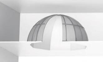


161 3D Design Dome Vault 3D Design 161


162 3D Design Funnels Free shapes 3D Design 162

163 Integrated Ceiling Components Vogl Access Panels Quick Access Whenever Needed Integrated Ceiling Components Perfect integration married with functional handling 163


 keeps the plasterboard insert from falling down while")
 prevents the access panel insert from falling out accidentally while being opened.")
164 Vogl Access Panels Benefits Quick access, homogeneous design Acoustic ceilings usually have more than one function. The space in the ceiling void must often be used for technical installations such as lighting, climate control, sound and fire protection systems. Vogl Access Panels are essential to keep these installations accessible for maintenance and repair even after the suspended ceiling has been installed. Vogl Access Panels offer top performance for easy access while fulfilling all aesthetic requirements at the same time. The benefits of Vogl Access Panels in detail: Available in 10.0/12.5/15.0 mm thickness for various applications Sturdy, high-quality aluminium frame for dimensional stability Multiple perforation patterns available ex factory Consistency in the rows of perforation throughout the ceiling Backed with acoustic fleece for high acoustic performance Sturdy catch mechanism (for panels > 300 mm) keeps the plasterboard insert from falling down while being opened Customised special designs can be realised Integrated Ceiling Components The standard catch mechanism (for Vogl Access Panels > 300 mm) prevents the access panel insert from falling out accidentally while being opened. For work in the ceiling void, the plasterboard insert can be conveniently detached and removed. The factory-installed perforated panel insert makes for easy integration into the ceiling surface. Exception: Random perforation panels should always be fitted into place at the job site. 164


165 Installation Guide 112 Vogl Access Panels - Installation Mark intended position of access panels on ceiling, considering that cutout has to be 4 mm larger than Vogl Access Panel / clear passage size. Then cut out marked section, making sure there are no panel joints within area of cutout. Note: Install trimmers of CD profiles in accordance with dimensions of access panel Observe distances between cutout and trimmer of min. 30 mm and max. 50 mm Mount 4 additional suspended brackets in corner areas of access panels It may be necessary to include additional suspended brackets so as not to exceed maximum bracket spacing The way to achieve the most accurate dimensions of the cutout is to use a plasterboard plane and/or sandpaper / abrasive mesh for the precision work. Chamfer visible side of acoustic design panel slightly to facilitate filling of joints later on. Then insert frame of Vogl Access Panel and hold it in place by means of a mounting aid matching perforation pattern. Predrill Vogl Access Panel frame with metal drill and fasten it with perforated panel screws SN. Be sure to use at least 2 screws per frame side for panel size < 500 x 500 mm and at least 3 screws per frame side for panel size > 500 x 500 mm. Then insert lid and check closing function. Cover row of perforation directly adjacent to access panel with masking tape. Now apply filling compound to access opening, remove masking tape right afterwards and knock away any excess filler to make it flush with ceiling surface. Observe relevant filler manufacturer's instructions. Integrated Ceiling Components After filler has dried, sand any edges or protruding material. Note: Our "Painting Instructions" are applicable for final coating Take out access panel lid and paint it separately to prevent paint from getting into narrow joint between frame and plasterboard insert Clean outer and inner frame thoroughly after coating Exception: With acoustic plaster ceilings, plasterboard insert should remain in ceiling surface in order to obtain uniform spray pattern. In this case make sure to clean joint between frame and lid after every spray application. 165


166 Integrated Ceiling Components VoglModu VoglModu Light to the site ready to go The creation of light strategies used to be a job for specialists. With the VoglModu illumination modules, the industry receives factory made light modules for the first time. They provide freedom of design and the additional advantage of easy installation. Whether for integration in suspended ceilings or as tailored illumination modules for floating ceilings: They offer diversity and multi-purpose use. The round or square design of the illumination modules harmonises ideally with the respective perforation patterns of the perforated panel ceilings. VoglModu is equally suitable as a functional eye-catcher for the design of smooth or plastered surfaces, whether wall or ceiling. The modular illumination system ready for installation: The fantastic effects of a light module with unexpected ease of assembly Prefabricated modules for simple wall and ceiling installation For integration in suspended perforated ceilings, plaster ceilings and smooth ceilings or as integration in floating ceilings to complement existing surfaces Perfectly flush and levelled perimeters in the finished areas Available in various types of shape, format and technical equipment Apart from the standard design, a dimmable or a DALI-compatible design with colour combinations is available Innovative colour design by simply covering the fluorescent lamps with coloured foils Integrated Ceiling Components Prefabricated for delivery to the job site: The light module is installed into the ceiling structure accurately fitting, which results in perfectly flush and levelled perimeters in the finished areas. Illumination in just a few steps: After connection to the building services and fitting of the fluorescent tubes, the frame which is already covered with a matt foil can be installed done! Benefits of VoglModu: Fits in perfectly with the ceiling appearance Perfectly easy to install in suspended ceilings or to integrate into prefabricated floating ceilings No special skills required Install large-area and coloured lighting As fast as lightning Can be used as a "standalone" light module Disadvantages of conventional ceiling lighting: No homogeneous integration into the existing ceiling design Intricate installation procedures Very limited illumination performance 166


167 Integrated Ceiling Components Vogl Strech Ceilings Vogl Stretch Ceilings Impressive play between form, colour and light The spectrum of design possibilities has been significantly expanded with acoustic design ceilings. Using colour, light and degrees of gloss, the elegant integration of stretch ceiling surfaces in acoustic design ceilings makes for a striking aesthetic appearance and, in its function as an illuminated ceiling, provides a gentle surface lighting with variable colour mix. The superb diversity of both colours and shapes is imposing! Clear geometric surfaces or freely defined shapes, combining various perforation patterns of the acoustic design panels, result in ceiling areas which are rich in contrast and can be level or stepped for 3D accentuation. In addition, Vogl's renowned economical, quick and reliable processing provides confidence in the final product. Vogl Stretch Ceilings offer almost unlimited freedom of design with: exciting surfaces and three-dimensional shapes contrasts between colours and degrees of gloss accentuated interaction of light and illumination more corporate design by using printed foils ideal combination possibilities with Vogl acoustic design ceilings in form, colour and performance Great when renovating: Great in wet environments: Minimal production and business down times No generation of dust and moisture Buildings generally remain operable No removal and disposal of existing ceilings No expensive new installations Suitable for spa areas through foil colours or colour-controlled illuminated ceilings Completely moistureresistant foils and profiles Splash protection for ceiling installations such as light and sound systems Reduction in the reverb time Integrated Ceiling Components 167

168 Integrated Ceiling Components 168

169 Working Methods VoglDouble Layer Fleece On One Level in Spite of Differences Working Methods The multitalent for your acoustic design ceiling 169


170 System - VoglDouble Layer Fleece Benefits/Applications Evenness easier than ever This is what drywall construction has waited for: Evenness between perforated and smooth gypsum boards used to be achieved by tedious spackling. It required a tremendous effort to equalize the small difference in height caused by the fleece laminated on the back of the perforated panels. The idea for achieving evenness in record time is brilliantly simple: VoglDouble Layer Fleece, which is self-adhesive and comes on rolls, ready for use, makes the levelling of height differences easier than ever. Brilliantly simple realisation of shadow gaps in contrasting colour for the perfectly designed ceiling. Optically appealing design of expansion joints by backing them in black or white. Benefits of the VoglDouble Layer Fleece system: Faster and more economical installation due to self-adhesive rolled material Tedious, time-consuming spackling is now a thing of the past Practical helper for many transition and connection issues Homogeneous material for perfect connection to fleecelaminated perforated panels Available in various tape widths for single or double application Available in white or black fleece colour Expansion joints For the coloured design of expansion joints in the ceiling. Your advantages when using VoglDouble Layer Fleece: Clean workmanship (no need to use a brush) Available in black or white Tape on rolls is applied quickly and easily Panel connections Flush panel connections between perforated panels and smooth plasterboards. Your advantages when using VoglDouble Layer Fleece: Quick installation with self-adhesive roll material No filling work connection between perforated panels and smooth plasterboards possible with VoglFriestape 20 mm Available in various tape widths Single-layer or multi-layer application possible (depending on height difference) Working Methods Wall connections Perfect wall connections in various designs. Whether as filled joint or as wall connection with shadow gap. Your advantages when using VoglDouble Layer Fleece: Functions as separating tape for a filled joint Colour of shadow gap available in white or black One product only for a variety of joint and connection applications 170

171 System - VoglDouble Layer Fleece Tender Specification VoglDouble Layer Fleece Item number Item description Dimensions VoglDouble Layer Fleece VAD 32 black Self-adhesive fleece, black VoglDouble Layer Fleece VAD 62 black Self-adhesive fleece, black VoglDouble Layer Fleece VAD 32 white Self-adhesive fleece, white VoglDouble Layer Fleece VAD 62 white Self-adhesive fleece, white Roll width 32 mm Roll length 200 m Roll width 62 mm Roll length 200 m Roll width 32 mm Roll length 200 m Roll width 62 mm Roll length 200 m Extra: Non-perforated frieze area, frieze areas w= mm of smooth plasterboards. Create frieze areas of smooth plasterboards, th=12.5 mm, transition from frieze area to perforated panel ceiling made with VoglDouble Layer Fleece (height compensation) and VoglFriestape 20 mm. Installation in accordance with manufacturer's instructions. Extra: Wall connection, with coloured shadow gap. Wall connection by means of a shadow gap (approx mm), coloured in black*/white* using VoglDouble Layer Fleece in accordance with manufacturer's instructions. Extra: Expansion joint for ceiling structure. Integrate expansion joints in aforementioned ceiling system. In this area, separate framework completely from the rest. Back expansion joint with a strip of plasterboard coloured with VoglDouble Layer Fleece in black*/white*. Screw down backing strip of plasterboard on one side only. Width of joint >5 mm. Insert edge protection profile, if required. Extra: Wall connection, with filled joint. Wall connection by means of filled joint using VoglDouble Layer Fleece as separating tape in accordance with manufacturer's instructions. * Delete as applicable Working Methods 171

172 Working Methods 172

173 Working Methods VoglFriestape-Set Perfect Borders and Perimeters Straight from the Roll Working Methods Perfectly simple frieze solutions 173


174 System VoglFriestape-Set Benefits Ceiling friezes in record time There are various ways of creating plain borders and perimeters for perforated plasterboard ceilings. They typically require intensive preplanning and tedious time consuming work on site. Now there is an efficient, clean and safe solution: The VoglFriestape-Set. With this method, non-perforated frieze areas can be produced quickly and economically, saving a great deal of time and hassle. The VoglFriestape-Set includes all accessories needed at the job site for making a frieze of any width. Just a few simple steps can produce a neat perimeter or border. Benefits of the VoglFriestape-Set system: The unique workmanship provides key advantages when creating frieze areas Quick, safe and clean workmanship No generation of dirt and dust Active sound absorption even with the frieze area Holes can be re-opened if required Filler cannot sink in, nor holes re-emerge Working Methods The VoglFriestape-Set includes the required material, tools and a detailed assembly instruction to ensure top quality workmanship and reliable results. The right tools at the right time in exactly the right place. 174
175 Installation Guide 106 VoglFriestape-Set Note: On cardboard surfaces of special types of plasterboard (waterproofed, impregnated, with graphite content, with white pre-coating, etc.), test the suitability of the VoglFriestape-Set on site. Owing to the reduced absorption capacity of these cardboard bases, the VoglFriestape-Set may otherwise cause holes to show or bubbles to form. Check cardboard area; sand panel joints and screw holes! Important! Failure to observe this may cause holes to show! Unpack tape (remove foil bag) approx. 24 h prior to installation to allow special paper to acclimatise. After sanding, wipe joint area with damp sponge to remove any dust or swarf. Load lambskin roller with liquid glue and roll it downward over paint grid. Vogl Liquid Glue = ready mix General site conditions / Manufacturer's instructions: Always store liquid glue in ** frost free environment ** Unpack tape (remove foil bag) approx. 24 h prior to installation to allow special paper to acclimatise. Stir liquid glue well before use! Working temperature should be at least +10 C and job site temperature not below +5 C Avoid sudden heating and cooling of rooms Relative humidity: % Self-levelling, cement or asphalt screeds must be fully dried no residual moisture Apply tape edge-to-edge only, i.e. no overlapping Use liquid glue only undiluted Roll liquid glue onto frieze area, then apply tape (making sure perforation is completely covered) and press it down with lambskin roller. Once tape has dried, open any half-open holes and then close them with joint compound. Different widths of tape can be combined without difficulty. However, make sure to lay tapes edge-to-edge. Under no circumstances should tapes be overlapped! Re-load lambskin roller with liquid glue and roll it downwards over paint grid. Vogl Liquid Glue = ready mix Apply another coat of liquid glue on frieze area, always working "wet on wet". Drying time: Min. 12 h Surface treatment for painters (in accordance with ATV painting work DIN 18363): Only apply coating by roller; spray application is not permitted! Prior to application of paint coat, a primer should generally be applied in accordance with manufacturer's specifications Manufacturer's recommended drying times for both primer and finishing coat must be strictly observed Alkaline coatings are unsuitable for plasterboards 3 coats of paint must be applied (1 prime coat + 2 finishing coats), and recommended drying times adhered to Always consult system manufacturer s technical data sheets for primers and finishing coats If necessary, smooth glue texture on tape s visible surface by gently sanding do not cross sand! Working Methods Once fully dry, any holes covered with tape can be re-opened using a sharp blade anytime. Scope of delivery, VoglFriestape-Set: Vogl Liquid Glue, Vogl Tape, stirring paddle, paint grid, lambskin roller, abrasive mesh, sanding paper, sponge. VoglFriestape-Set is available in various tape widths (20 mm, 50 mm, 75 mm, 100 mm, 150 mm). Note: VoglFriestape-Set is only recommended for hole sizes up to max. 20 mm. 175


176 System VoglFriestape-Set Tender specification VoglFriestape-Set Item number Item description Tape dimensions in linear metres VoglFriestape-Set 20 mm tape width 20 mm 2 rolls of tape 20 mm = 200 linm VoglFriestape-Set 50 mm tape width 50 mm 3 rolls of tape 50 mm = 150 linm VoglFriestape-Set 75 mm tape width 75 mm 2 rolls of tape 75 mm = 100 linm VoglFriestape-Set 100 mm tape width 100 mm 1 roll of tape 100 mm = 50 linm VoglFriestape-Set 150 mm tape width 150 mm 1 roll of tape 150 mm = 50 linm Extra: Creation of frieze area using VoglFriestape For extra, create frieze area using VoglFriestape in VoglFriestape-Set, in accordance with manufacturer's instructions. Frieze width: mm Illustration shows item Working Methods 176

177 Acoustic Ceilings Acoustics and Sound Absorption Design and Acoustics Brought into Harmony Sound absorption values Sound Absorption Values 177
178 Sound Absorption Values Product Data Sheet Acoustic Design Panel 6/18R Determination of sound absorption coefficient as per DIN EN ISO 354 Rating of sound absorption coefficient as per DIN EN ISO Panel thickness: th = 12.5 mm Mass per unit area: 9.10 kg/m 2 Perforated area: 8.7 % Fire rating as per DIN 4102: A2, "non-flammable" Fire behaviour as per DIN EN : A2-s1, d0 Back of panel laminated with acoustic fleece AV 2010 Rated sound absorption coefficient αw = 0.55 Sound absorption class D (absorbing) Single number rating as per ASTM C 423: SAA = 0.51 Classification as per ASTM E 1264: NRC = 0.50 Air gap: 200 mm ,000 2,000 4,000 Octave centre frequency [Hz] ,000 2,000 4,000 Sound absorption coefficient α p Back of panel laminated with acoustic fleece AV 2010 backed with glass wool Mineral wool panel SSP 1, 30 mm Rated sound absorption coefficient αw = 0.55 Sound absorption class D (absorbing) Single number rating as per ASTM C 423: SAA = 0.53 Classification as per ASTM E 1264: NRC = ,000 2,000 4,000 Air gap: 200 mm Sound Absorption Values Octave centre frequency [Hz] ,000 2,000 4,000 Sound absorption coefficient α p Find all our product documentation in many languages, always up-to-date and available at any time, on our website under: under "Downloads" 178
179 Sound Absorption Values Product Data Sheet Acoustic Design Panel 8/18R Determination of sound absorption coefficient as per DIN EN ISO 354 Rating of sound absorption coefficient as per DIN EN ISO Panel thickness: th = 12.5 mm Mass per unit area: 8.50 kg/m 2 Perforated area: 15.5 % Fire rating as per DIN 4102: A2, "non-flammable" Fire behaviour as per DIN EN : A2-s1, d0 Back of panel laminated with acoustic fleece AV 2010 Rated sound absorption coefficient αw = 0.70 Sound absorption class C (highly absorbing) Single number rating as per ASTM C 423: SAA = 0.67 Classification as per ASTM E 1264: NRC = 0.65 Air gap: 200 mm ,000 2,000 4,000 Octave centre frequency [Hz] ,000 2,000 4,000 Sound absorption coefficient α p Back of panel laminated with acoustic fleece AV 2010 backed with glass wool Mineral wool panel SSP 1, 30 mm Rated sound absorption coefficient αw = 0.75 Sound absorption class C (highly absorbing) Single number rating as per ASTM C 423: SAA = 0.72 Classification as per ASTM E 1264: NRC = ,000 2,000 4,000 Air gap: 200 mm Octave centre frequency [Hz] ,000 2,000 4,000 Sound absorption coefficient α p Find all our product documentation in many languages, always up-to-date and available at any time, on our website under: under "Downloads" Sound Absorption Values 179
180 Sound Absorption Values Product Data Sheet Acoustic Design Panel 10/23R Determination of sound absorption coefficient as per DIN EN ISO 354 Rating of sound absorption coefficient as per DIN EN ISO Panel thickness: th = 12.5 mm Mass per unit area: 8.50 kg/m 2 Perforated area: 14.8 % Fire rating as per DIN 4102: A2, "non-flammable" Fire behaviour as per DIN EN : A2-s1, d0 Back of panel laminated with acoustic fleece AV 2010 Rated sound absorption coefficient αw = 0.70 Sound absorption class C (highly absorbing) Single number rating as per ASTM C 423: SAA = 0.65 Classification as per ASTM E 1264: NRC = 0.65 Air gap: 200 mm ,000 2,000 4,000 Octave centre frequency [Hz] ,000 2,000 4,000 Sound absorption coefficient α p Back of panel laminated with acoustic fleece AV 2010 backed with glass wool Mineral wool panel SSP 1, 30 mm Rated sound absorption coefficient αw = 0.70 Sound absorption class C (highly absorbing) Single number rating as per ASTM C 423: SAA = 0.69 Classification as per ASTM E 1264: NRC = ,000 2,000 4,000 Air gap: 200 mm Sound Absorption Values Octave centre frequency [Hz] ,000 2,000 4,000 Sound absorption coefficient α p Find all our product documentation in many languages, always up-to-date and available at any time, on our website under: under "Downloads" 180
181 Sound Absorption Values Product Data Sheet Acoustic Design Panel 12/25R Determination of sound absorption coefficient as per DIN EN ISO 354 Rating of sound absorption coefficient as per DIN EN ISO Panel thickness: th = 12.5 mm Mass per unit area: 8.20 kg/m 2 Perforated area: 18.1 % Fire rating as per DIN 4102: A2, "non-flammable" Fire behaviour as per DIN EN : A2-s1, d0 Back of panel laminated with acoustic fleece AV 2010 Rated sound absorption coefficient αw = 0.70 Sound absorption class C (highly absorbing) Single number rating as per ASTM C 423: SAA = 0.69 Classification as per ASTM E 1264: NRC = 0.70 Air gap: 200 mm ,000 2,000 4,000 Octave centre frequency [Hz] ,000 2,000 4,000 Sound absorption coefficient α p Back of panel laminated with acoustic fleece AV 2010 backed with glass wool Mineral wool panel SSP 1, 30 mm Rated sound absorption coefficient αw = 0.80 Sound absorption class B (extremely absorbing) Single number rating as per ASTM C 423: SAA = 0.75 Classification as per ASTM E 1264: NRC = ,000 2,000 4,000 Air gap: 200 mm Octave centre frequency [Hz] ,000 2,000 4,000 Sound absorption coefficient α p Find all our product documentation in many languages, always up-to-date and available at any time, on our website under: under "Downloads" Sound Absorption Values 181
182 Sound Absorption Values Product Data Sheet Acoustic Design Panel 15/30R Determination of sound absorption coefficient as per DIN EN ISO 354 Rating of sound absorption coefficient as per DIN EN ISO Panel thickness: th = 12.5 mm Mass per unit area: 8.00 kg/m 2 Perforated area: 19.6 % Fire rating as per DIN 4102: A2, "non-flammable" Fire behaviour as per DIN EN : A2-s1, d0 Back of panel laminated with acoustic fleece AV 2010 Rated sound absorption coefficient αw = 0.75 Sound absorption class C (highly absorbing) Single number rating as per ASTM C 423: SAA = 0.69 Classification as per ASTM E 1264: NRC = 0.70 Air gap: 200 mm ,000 2,000 4,000 Octave centre frequency [Hz] ,000 2,000 4,000 Sound absorption coefficient α p Back of panel laminated with acoustic fleece AV 2010 backed with glass wool Mineral wool panel SSP 1, 30 mm Rated sound absorption coefficient αw = 0.80 Sound absorption class B (extremely absorbing) Single number rating as per ASTM C 423: SAA = 0.77 Classification as per ASTM E 1264: NRC = ,000 2,000 4,000 Air gap: 200 mm Sound Absorption Values Octave centre frequency [Hz] ,000 2,000 4,000 Sound absorption coefficient α p Find all our product documentation in many languages, always up-to-date and available at any time, on our website under: under "Downloads" 182
183 Sound Absorption Values Product Data Sheet Acoustic Design Panel 8/12/50R Determination of sound absorption coefficient as per DIN EN ISO 354 Rating of sound absorption coefficient as per DIN EN ISO Panel thickness: th = 12.5 mm Mass per unit area: 8.70 kg/m 2 Perforated area: 13.1 % Fire rating as per DIN 4102: A2, "non-flammable" Fire behaviour as per DIN EN : A2-s1, d0 Back of panel laminated with acoustic fleece AV 2010 Rated sound absorption coefficient αw = 0.65 Sound absorption class C (highly absorbing) Single number rating as per ASTM C 423: SAA = 0.62 Classification as per ASTM E 1264: NRC = 0.60 Air gap: 200 mm ,000 2,000 4,000 Octave centre frequency [Hz] ,000 2,000 4,000 Sound absorption coefficient α p Back of panel laminated with acoustic fleece AV 2010 backed with glass wool Mineral wool panel SSP 1, 30 mm Rated sound absorption coefficient αw = 0.70 Sound absorption class C (highly absorbing) Single number rating as per ASTM C 423: SAA = 0.66 Classification as per ASTM E 1264: NRC = ,000 2,000 4,000 Air gap: 200 mm Octave centre frequency [Hz] ,000 2,000 4,000 Sound absorption coefficient α p Find all our product documentation in many languages, always up-to-date and available at any time, on our website under: under "Downloads" Sound Absorption Values 183
184 Sound Absorption Values Product Data Sheet Acoustic Design Panel 12/20/66R Determination of sound absorption coefficient as per DIN EN ISO 354 Rating of sound absorption coefficient as per DIN EN ISO Panel thickness: th = 12.5 mm Mass per unit area: 8.00 kg/m 2 Perforated area: 19.6 % Fire rating as per DIN 4102: A2, "non-flammable" Fire behaviour as per DIN EN : A2-s1, d0 Back of panel laminated with acoustic fleece AV 2010 Rated sound absorption coefficient αw = 0.70 Sound absorption class C (highly absorbing) Single number rating as per ASTM C 423: SAA = 0.69 Classification as per ASTM E 1264: NRC = 0.70 Air gap: 200 mm ,000 2,000 4,000 Octave centre frequency [Hz] ,000 2,000 4,000 Sound absorption coefficient α p Back of panel laminated with acoustic fleece AV 2010 backed with glass wool Mineral wool panel SSP 1, 30 mm Rated sound absorption coefficient αw = 0.80 Sound absorption class B (extremely absorbing) Single number rating as per ASTM C 423: SAA = 0.77 Classification as per ASTM E 1264: NRC = ,000 2,000 4,000 Air gap: 200 mm Sound Absorption Values Octave centre frequency [Hz] ,000 2,000 4,000 Sound absorption coefficient α p Find all our product documentation in many languages, always up-to-date and available at any time, on our website under: under "Downloads" 184
185 Sound Absorption Values Product Data Sheet Acoustic Design Panel 8/18Q Determination of sound absorption coefficient as per DIN EN ISO 354 Rating of sound absorption coefficient as per DIN EN ISO Panel thickness: th = 12.5 mm Mass per unit area: 8.00 kg/m 2 Perforated area: 19.8 % Fire rating as per DIN 4102: A2, "non-flammable" Fire behaviour as per DIN EN : A2-s1, d0 Back of panel laminated with acoustic fleece AV 2010 Rated sound absorption coefficient αw = 0.75 Sound absorption class C (highly absorbing) Single number rating as per ASTM C 423: SAA = 0.72 Classification as per ASTM E 1264: NRC = 0.70 Air gap: 200 mm ,000 2,000 4,000 Octave centre frequency [Hz] ,000 2,000 4,000 Sound absorption coefficient α p Back of panel laminated with acoustic fleece AV 2010 backed with glass wool Mineral wool panel SSP 1, 30 mm Rated sound absorption coefficient αw = 0.85 Sound absorption class B (extremely absorbing) Single number rating as per ASTM C 423: SAA = 0.80 Classification as per ASTM E 1264: NRC = ,000 2,000 4,000 Air gap: 200 mm Octave centre frequency [Hz] ,000 2,000 4,000 Sound absorption coefficient α p Find all our product documentation in many languages, always up-to-date and available at any time, on our website under: under "Downloads" Sound Absorption Values 185
186 Sound Absorption Values Product Data Sheet Acoustic Design Panel 12/25Q Determination of sound absorption coefficient as per DIN EN ISO 354 Rating of sound absorption coefficient as per DIN EN ISO Panel thickness: th = 12.5 mm Mass per unit area: 7.70 kg/m 2 Perforated area: 23.0 % Fire rating as per DIN 4102: A2, "non-flammable" Fire behaviour as per DIN EN : A2-s1, d0 Back of panel laminated with acoustic fleece AV 2010 Rated sound absorption coefficient αw = 0.75 Sound absorption class C (highly absorbing) Single number rating as per ASTM C 423: SAA = 0.74 Classification as per ASTM E 1264: NRC = 0.75 Air gap: 200 mm ,000 2,000 4,000 Octave centre frequency [Hz] ,000 2,000 4,000 Sound absorption coefficient α p Back of panel laminated with acoustic fleece AV 2010 backed with glass wool Mineral wool panel SSP 1, 30 mm Rated sound absorption coefficient αw = 0.90 Sound absorption class A (extremely absorbing) Single number rating as per ASTM C 423: SAA = 0.83 Classification as per ASTM E 1264: NRC = 0.85 Air gap: 200 mm ,000 2,000 4,000 Sound Absorption Values Octave centre frequency [Hz] ,000 2,000 4,000 Sound absorption coefficient α p Find all our product documentation in many languages, always up-to-date and available at any time, on our website under: under "Downloads" 186
187 Sound Absorption Values Product Data Sheet Acoustic Design Panel 8/15/20R Determination of sound absorption coefficient as per DIN EN ISO 354 Rating of sound absorption coefficient as per DIN EN ISO Panel thickness: th = 12.5 mm Mass per unit area: 9.10 kg/m 2 Perforated area: 9.5 % Fire rating as per DIN 4102: A2, "non-flammable" Fire behaviour as per DIN EN : A2-s1, d0 Back of panel laminated with acoustic fleece AV 2010 Rated sound absorption coefficient αw = 0.55 Sound absorption class D (absorbing) Single number rating as per ASTM C 423: SAA = 0.52 Classification as per ASTM E 1264: NRC = 0.50 Air gap: 200 mm ,000 2,000 4,000 Octave centre frequency [Hz] ,000 2,000 4,000 Sound absorption coefficient α p Back of panel laminated with acoustic fleece AV 2010 backed with glass wool Mineral wool panel SSP 1, 30 mm Rated sound absorption coefficient αw = 0.60 Sound absorption class C (highly absorbing) Single number rating as per ASTM C 423: SAA = 0.54 Classification as per ASTM E 1264: NRC = ,000 2,000 4,000 Air gap: 200 mm Octave centre frequency [Hz] ,000 2,000 4,000 Sound absorption coefficient α p Find all our product documentation in many languages, always up-to-date and available at any time, on our website under: under "Downloads" Sound Absorption Values 187
188 Sound Absorption Values Product Data Sheet Acoustic Design Panel 12/20/35R Determination of sound absorption coefficient as per DIN EN ISO 354 Rating of sound absorption coefficient as per DIN EN ISO Panel thickness: th = 12.5 mm Mass per unit area: 8.90 kg/m 2 Perforated area: 11.0 % Fire rating as per DIN 4102: A2, "non-flammable" Fire behaviour as per DIN EN : A2-s1, d0 Back of panel laminated with acoustic fleece AV 2010 Rated sound absorption coefficient αw = 0.55 Sound absorption class D (absorbing) Single number rating as per ASTM C 423: SAA = 0.55 Classification as per ASTM E 1264: NRC = 0.55 Air gap: 200 mm ,000 2,000 4,000 Octave centre frequency [Hz] ,000 2,000 4,000 Sound absorption coefficient α p Back of panel laminated with acoustic fleece AV 2010 backed with glass wool Mineral wool panel SSP 1, 30 mm Rated sound absorption coefficient αw = 0.60 Sound absorption class C (highly absorbing) Single number rating as per ASTM C 423: SAA = 0.58 Classification as per ASTM E 1264: NRC = ,000 2,000 4,000 Air gap: 200 mm Sound Absorption Values Octave centre frequency [Hz] ,000 2,000 4,000 Sound absorption coefficient α p Find all our product documentation in many languages, always up-to-date and available at any time, on our website under: under "Downloads" 188
189 Sound Absorption Values Product Data Sheet Acoustic Plaster System Panel 12/25Q Determination of sound absorption coefficient as per DIN EN ISO 354 Rating of sound absorption coefficient as per DIN EN ISO Panel thickness: th = 12.5 mm Mass per unit area: 7.7 kg/m 2 Perforated area: 22.9 % Fire rating as per DIN 4102: A2, "non-flammable" Fire behaviour as per DIN EN : A2-s1, d0 System structure: Wallpapered with plaster base fleece on site and finished with VoglToptec acoustic plaster Nano SF 1.2 Back of panel laminated with acoustic fleece AV Rated sound absorption coefficient αw = 0.75 Sound absorption class C (highly absorbing) Single number rating as per ASTM C 423: SAA = 0.73 Classification as per ASTM E 1264: NRC = Air gap: 200 mm ,000 2,000 4,000 Octave centre frequency [Hz] ,000 2,000 4,000 Sound absorption coefficient α p Back of panel laminated with acoustic fleece AV Mineral wool panel SSP 1, 30 mm Rated sound absorption coefficient αw = 0.90 Sound absorption class A (extremely absorbing) Single number rating as per ASTM C 423: SAA = 0.85 Classification as per ASTM E 1264: NRC = Air gap: 200 mm ,000 2,000 4,000 Octave centre frequency [Hz] ,000 2,000 4,000 Sound absorption coefficient α p Find all our product documentation in many languages, always up-to-date and available at any time, on our website under: under "Downloads" Sound Absorption Values 189

 0.8 0.")
190 Sound Absorption Values Product Data Sheet Ultracoustic Panel 12/25R DLV Determination of sound absorption coefficient as per DIN EN ISO 354 Rating of sound absorption coefficient as per DIN EN ISO Panel thickness: th = 12.5 mm Mass per unit area: 6.5 kg/m 2 Perforated area: 35.3 % Fire rating as per DIN 4102: A2, "non-flammable" Fire behaviour as per DIN EN : A2-s1, d0 System structure: Wallpapered with plaster base fleece on site and finished with VoglToptec acoustic plaster Nano SF 1.2 Back of panel laminated with acoustic fleece AV Rated sound absorption coefficient αw = 0.80 Sound absorption class B (extremely absorbing) Single number rating as per ASTM C 423: SAA = 0.75 Classification as per ASTM E 1264: NRC = Air gap: 200 mm ,000 2,000 4,000 Octave centre frequency [Hz] ,000 2,000 4,000 Sound absorption coefficient α p Back of panel laminated with acoustic fleece AV Mineral wool panel SSP 1, 30 mm Rated sound absorption coefficient αw = 0.95 Sound absorption class A (extremely absorbing) Single number rating as per ASTM C 423: SAA = 0.91 Classification as per ASTM E 1264: NRC = Air gap: 200 mm ,000 2,000 4,000 Sound Absorption Values Octave centre frequency [Hz] ,000 2,000 4,000 Sound absorption coefficient α p Find all our product documentation in many languages, always up-to-date and available at any time, on our website under: under "Downloads" 190
 Installation of acoustic design ceilings Various joint systems Others Personal data Company Contact partner Street, house no.")
191 System Training Our know-how for your result reliability Inquiry I am interested in the following event: Acoustic plaster system VoglToptec Applications and processing Framework for acoustic design ceilings ( perforated ceilings ) Installation of acoustic design ceilings Various joint systems Others Personal data Company Contact partner Street, house no. Postcode, town/city Date / stamp / signature Phone Having a long journey, I would like to arrive the day before the training course and require accommodation for one night. Please send me some hotel addresses with your special rates. Some more colleagues / customers are interested. I expect to come with people. We are looking forward to your visit in Emskirchen! (Emskirchen is located 25 km to the northwest of Nuremberg) You have any questions in advance? We are glad to assist you! Phone:
192 Index A Abrasive mesh 53 Access panels (general) 163 Acoustic floating ceiling 44 Acoustic plaster system panel 189 Acoustics and sound absorption 177 Additional charges 57 Adjustable vibration bracket 17 Anchor bracket 17 Anchor fast suspension 16 Anchor suspension 16 Angled connectors 18 Applications, VoglDouble Layer Fleece 170 B Ball-impact Resistant Ceiling (general) 101 Benefits, Ball-impact Resistant Ceiling 102 Benefits, Compound Seam 92 Benefits, GSG4 Joint 80 Benefits, Visible Chamfer 72 Benefits, Vogl Access Panels 164 Benefits, VoglDouble Layer Fleece 170 Benefits, VoglFriestape-Set 174 Benefits, VoglFuge 60 Benefits, VoglThermal Tiles 142 Benefits, VoglThermotop 131 Benefits, VoglToptec 118 Bucket trowel 54 C CD profile 15 Ceiling Tiles (general) 109 Chamfer plane 53 Chapter Overview 3 Compound Seam (general) 91 Connection pliers 53 Connectors 18, 24 Cross connector 17 Customised designs, VoglToptec 123 Customised designs, GSG4 Joint 83 Customised designs, VoglFuge 63 D Direct mounting clip 16 Direct mounting vibration clip 20 Direct suspended bracket 16 Direct vibration hanger 20 Double spring clip 22 Drilling templates 55 Drywall saw 54 Drywall screw 25 E Easy-span hanger 22 Editorial 6 Europallets 57 Eyelet wire 19, 21 F FAQ, VoglThermotop 138 Fastening clip 16 Framework, Ball-impact Resistant Ceiling 105 Framework, Compound Seam 94 Framework, GSG4 Joint 84 Framework, Visible Chamfer 74 Framework, VoglFuge 64 Framework, VoglThermotop 132 Framework, VoglToptec 121 G General Terms and Conditions 196 GSG4 Joint (general) 79 H Hand sander 53 Handle with knurled screw 54 Hooked wire 22 I Installation guide, Ceiling Tiles 116 Installation guide, Compound Seam 96 Installation guide, GSG4 Joint 86 Installation guide, Visible Chamfer 76 Installation guide, Vogl Access Panels 165 Installation guide, VoglFriestape-Set 175 Installation guide, VoglFuge 66 Installation guide, VoglThermal Tiles 143 Installation guide, VoglThermotop 135 Installation guide, VoglToptec 124 Installation of ceiling panels, VoglFuge system 66 Interseroh 57 J Joint finishing, VoglFuge system 68 Joint sealing set 54 M Moulded Components (general) 147 Mounting aid 55 P Panel pallet 57 Parcel service charges 57 Perforated panel screw 25 Perforation patterns, GSG4 Joint 82 Perforation patterns, VoglFuge 62 Perforation wheel 54 Performance values, VoglThermal Tiles 144 Performance values, VoglThermotop 136 Philosophy 7 Picture gallery 4 Plastic foil hood 57 Product portfolio 9 Products 11 Prouct range, Adhesive Seam 32 Prouct range, Ball-impact Resistant Ceiling 103 Prouct range, Ceiling Tiles 39 Prouct range, Compound Seam 27 Prouct range, Cooling and Heating Ceilings
193 Index Prouct range, GSG4 Joint 29 Prouct range, Moulded components 45 Prouct range, Visible Chamfer 31 Prouct range, Vogl Access panels 49 Prouct range, Vogl Stretch Ceilings 52 Prouct range, VoglDouble layer fleece 53 Prouct range, VoglFriestape Set 53 Prouct range, VoglFuge 26 Prouct range, VoglModu 51 Prouct range, VoglThermal Tiles 38 Prouct range, VoglThermotec Compound Seam 35 Prouct range, VoglThermotec PLUS Compound Seam 37 Prouct range, VoglThermotec PLUS VoglFuge 36 Prouct range, VoglThermotec VoglFuge 34 Prouct range, VoglToptec 43 Prouct range, Working equipment 53 Q Quick hanger 22, 24 R Recycling certificate 57 Rentex 52 Replacement blades for chamfer plane 53 Round rasp 54 S Sanding paper 53 Screw head trowel 54 Screwdriver handle trowel 54 Service portfolio 10 Services 57 Shipping costs 57 Sound absorption values 177 Sound absorption values, acoustic design panel 178 Sound absorption values, ultracoustic panel 190 Spare parts for joint sealing set 54 Special palletising 57 Stretch Ceiling (general) 167 Support clip 17 Surcharge 57 System components, VoglToptec 120 System description, Ball-impact Resistant Ceiling 106 System description, Compound Seam 95 System description, Visible Chamfer 75 System description, VoglThermotop 130, 134 System description, VoglToptec 122 System structure, Ceiling Tiles 114 System training, framework 90 System training, inquiry 191 System training, installation 100 System training, VoglToptec 140 T Tapping screw 25 Tender specification, Ball-impact Resistant Ceiling 108 Tender specification, Compound Seam 99 Tender specification, GSG4 Joint 89 Tender specification, Visible Chamfer 78 Tender specification, VoglDouble Layer Fleece 171 Tender specification, VoglFriestape-Set 176 Tender specification, VoglFuge 69 Tender specification, VoglThermal Tiles 145 Tender specification, VoglThermotop 139 Tender specification, VoglToptec 128 Twisting anchor bracket 17 U UA cross connector 17 UD profile 15 Universal connector 18 Universal mixing paddle 54 Unloading costs 57 V Vernier bottom part 20 Vernier connector 19 Vernier coupling 20 Vernier hanger 20 Vernier rod 20 Vernier security pin 19 Vernier short hanger 23, 24 Vernier suspended bracket 23, 24, 115 Vernier top part 19, 21 Vertical connectors 18 Visible Chamfer (general) 71 Vogl acoustic design ceilings, VoglFuge system 26, 61 Vogl ceiling paint Colormix Plus 56 Vogl ceiling paint White Premium 56 Vogl Colour Panel 33 VoglDouble Layer Fleece (general) 169 VoglFriestape-Set (general) 173 VoglFuge (general) 59 VoglModu (general) 166 Vogl Supergrund primer 55 VoglThermotop (general) 129 VoglToptec (general) 117 VoglToptec Akustik Color Nano SF 56 VoglToptec Akustik Nano SF 56 VoglToptec plaster base fleece 56 VoglToptec plaster base fleece, small 56 VoglToptec special adhesive 56 VoglToptec wallpaper smoother 56 W Wafer head screw
194 Picture credits Page 1 photo: Andreas Molatta Page 71 photo: Thilo Jaeckel Page 131 right picture column, 3rd from top, photo: Thilo Jaeckel Page 4 center left: Janice O Connell Page 72 right picture column, 1st from top, photo: Thilo Jaeckel Page 131 bottom, photos: Page 4 Page 4 Page 6 Page 7 Page 7 Page 7 Page 7 Page 7 Page 7 Page 7 Page 7 Page 7 Page 8 Page 9 Page 9 Page 9 Page 9 Page 9 Page 11 Page 11 Page 11 Page 11 Page 11 Page 11 Page 11 Page 11 Page 12 center right: Donal Murphy bottom: Nico Herzog photos: top left, photo: Thilo Jaeckel top centre, photo: Uta Kellermann top right, photo: Donal Murphy centre left, photo: Torsten Elger centre centre, photo: centre right, Rentex Wand- und Deckensysteme GmbH, photo: Ansorg GmbH bottom left, Rentex Wand- und Deckensysteme GmbH, photo: Damian Zimmermann bottom centre, photo: bottom right, photo: photos: right picture column, 1st from top, photo: Nico Herzog right picture column, 2nd from top, photo: Torsten Elger centre, Rentex Wand- und Deckensysteme GmbH, photo: Jens Lyncker bottom left, photo: Donal Murphy bottom right, photo: top centre, photo: Thilo Jaeckel top right, photo: Thilo Jaeckel centre left, photo: centre centre, photo: centre right, photo: bottom left, photo: Werner Huthmacher bottom centre, photo: bottom right, photo: photo: Werner Huthmacher Page 72 Page 72 Page 72 Page 78 Page 79 Page 80 Page 80 Page 80 Page 80 Page 83 Page 89 Page 90 Page 90 Page 91 Page 91 Page 92 Page 92 Page 92 Page 92 Page 99 right picture column, 2nd from top, photo: Thilo Jaeckel centre side-by-side, photos: bottom, photo: Thilo Jaeckel photo: Thilo Jaeckel photo: Donal Murphy right picture column, 1st from top, photo: Werner Huthmacher right picture column, 2nd from top, photo: Thilo Jaeckel right picture column, 2nd from bottom, photo: bottom, photo: Donal Murphy photo: Thilo Jaeckel photo: Thilo Jaeckel top right, photo: bottom right, photo: Thilo Jaeckel top, photo: Novy Gilbert bottom left, photo: top right, photo: Kurt Kuball centre right, photo: Anke Müllerklein bottom left, photo: Donal Murphy bottom right, photo: Kurt Kuball photo: Kurt Kuball Page 100 photos: Page 101 top, photo: Thilo Jaeckel Page 101 bottom left, photo: Page 102 top right, photo: istock.com, Entienou Page 102 centre left, photo: Page 102 centre right, photo: istock.com, Oksana Struk Page 102 bottom, photos: Page 104 bottom left, photo: Page 134 bottom left, photo: Bettina Bauer Page 134 bottom right, photo: Page 135 bottom left, photo: Kurt Kuball Page 135 bottom right, photo: Michael Bogumil Page 138 photo: Werner Huthmacher Page 139 bottom left, photo: Angelo Kaunat Page 139 bottom right, photo: Zooey Braun Page 140 photos: Page 141 photos: Nadja Giese Page 142 top right, photo: Nadja Giese Page 142 centre right, photo: Thilo Jaeckel Page 145 photo: Nadja Giese Page 146 Rentex Wand- und Deckensysteme GmbH, photo: Jens Lyncker Page 147 top, photo: Uta Kellermann Page 147 bottom left, photo: Thilo Jaeckel Page 148 top right, photo: Donal Murphy Page 148 centre side-by-side, photos: Page 149 photo: Page 157 photo: Uta Kellermann Page 158 photo: Angelo Kaunat Page 159 photo: Thilo Jaeckel Page 160 top right, photo: Zooey Braun Page 160 centre left, photo: Michael Bogumil Page 160 bottom, photos: Page 162 photo: Torsten Elger Page 163 top, photo: Martina Draper Page 163 bottom left, photo: Page 164 right picture column, 1st from top, photo: Jarek Matla Page 13 Rentex Wand- und Deckensysteme GmbH, photo: Jens Lyncker Page 104 bottom right, photo: Thilo Jaeckel Page 164 right picture column, 2nd from top, photo: Walter Henisch Page 14 Page 23 Page 32 Page 33 Page 33 Page 33 Page 44 Page 44 Page 44 Page 46 Page 47 Page 48 Page 51 Page 52 Page 52 Page 52 Page 58 Page 59 Page 60 Page 60 Page 60 Page 60 Page 60 Page 63 Page 69 Page 70 photo: photo: Donal Murphy photo: centre left, photo: Michael Bogumil centre right, photo: bottom left, photo: top right, photo: Michael Godehardt centre right, photo: Donal Murphy bottom, photo: Zooey Braun photos: photo: Thilo Jaeckel photos: photos: centre right, Rentex Wand- und Deckensysteme GmbH, photo: Damian Zimmermann bottom left, Rentex Wand- und Deckensysteme GmbH, photo: Jens Lyncker bottom right, photo: Hertha Hurnaus/Architektur: lakonis Architekten photo: Nico Herzog photo: Donal Murphy right picture column, 1st from top, photo: Donal Murphy right picture column, 2nd from top, photo: Karl Thomas centre left, photo: centre right, photo: Angelo Kaunat bottom, photo: photo: Thilo Jaeckel photo: Walter Henisch Rentex Wand- und Deckensysteme GmbH, photo: Damian Zimmermann Page 107 photo: Page 108 photo: Thilo Jaeckel Page 109 top left, photo: Thilo Jaeckel Page 109 right picture column, 1st from top, photo: Page 109 right picture column, 2nd from top, photo: Page 109 bottom left, photo: Page 116 photo: Anke Müllerklein Page 117 top, photo: Daniel Vieser Page 117 bottom left, photo: Page 118 top left, photo: Page 118 top right, photo: Thilo Jaeckel Page 118 centre right, photo: HG Esch Page 118 bottom, photos: Page 119 photos: Page 123 top left, photo: Page 123 top right, photo: Thilo Jaeckel Page 123 bottom left, photo: Page 123 bottom right, photo: Thilo Jaeckel Page 127 centre left, photo: Page 127 centre right, photo: Thilo Jaeckel Page 128 photo: Daniel Vieser Page 129 top, photo: Werner Huthmacher Page 129 bottom left, photo: Page 130 photo: Page 131 right picture column, 1st from top, photo: Helmut Frohringer Page 131 centre left, photo: Page 131 centre right, photo: Werner Huthmacher Page 164 right picture column, 3rd from top, photo: Page 164 centre left, photo: Page 164 bottom left, photo: Walter Henisch Page 164 bottom right, photo: Page 166 top right, Rentex Wand- und Deckensysteme GmbH, photo: Thomas Mayer Page 166 centre left, photo: Page 167 top right, Rentex Wand- und Deckensysteme GmbH, photo: Day & Light Lichtplanung GbR Page 167 centre right, Rentex Wand- und Deckensysteme GmbH, photo: Ansorg GmbH Page 167 bottom left, photo: Jörg Hempel Page 168 photo: Walter Henisch Page 169 top, photo: Donal Murphy Page 169 bottom left, photo: Page 170 photos: Page 172 photo: Stefan Müller Page 173 top, photo: Donal Murphy Page 173 bottom left, photo: Page 174 top right, photo: Kurt Kuball Page 174 centre left, photo: Uta Kellermann Page 174 centre right, photo: Walter Henisch Page 174 bottom, photos: Page 176 photo: Thilo Jaeckel Page 177 photos: Page 191 photo: Page 195 photo: Karl Thomas Page 198 photo: Zooey Braun 194


195 Online Support Use our multiple online resources: es: References Videos Picture gallery Flyers Newsletter Detailed designs Specifications Installation guides as PDF and animated Online support, making your job easier: 195
196 General Terms and Conditions 1 General All contracts, deliveries and services are regulated exclusively by our following General Terms and Conditions. They apply with regard to merchants and companies as well as for all future business relationships without the need for explicit repeated reference thereto. Any contradictory General Terms and Conditions, in particular the customer's Conditions of Purchase, are only valid if confirmed by us. 2 Offer and Acceptance, Service Description Our offers are non-binding. The acceptance of a still valid offer leads to a binding order only if and when confirmed by us in writing. Our written confirmation of the order is exclusively relevant for the terms of the contract. Technical data and descriptions in our product information or marketing materials do not constitute a guaranty of quality or durability and particularly do not guarantee any specific properties. In case of sample-based sales, the Purchaser shall inspect the Goods immediately and report any complaints within a period of five days in writing. After this period has expired, the sample or specimen is deemed to be accepted and the desired contractual relationship comes into effect. Customised orders are only realised when the technical requirements put forth by the Purchaser are unambiguous and feasible and are confirmed by us in writing. Models and tools remain our property, even when the customer has paid for their construction. 3 Prices, Terms of Payment and Default The prices specified in the respective contract, particularly in the order form or the order confirmation, are valid plus statutory VAT (value added tax). If a price is not explicitly defined, our respective price lists at the time of the contract are valid. The weights and quantities defined by us determine the calculation of the prices unless the Purchaser objects immediately upon receipt of the Goods and proves the contrary. Packaging and transportation costs, and any costs of transportation insurance, are charged in addition. Unless otherwise agreed, our invoices are payable within 14 days of receipt. After this period has expired, the Purchaser is automatically in default and has to pay interest from then on in the amount of currently five percentage points above the base rate of the European Central Bank. Discounts are only given if separately agreed upon. The final invoice amount minus shipping costs, packaging costs and pallet value is discountable. If circumstances become known that give rise to justifiable doubt about the Purchaser's ability to pay, we have the right to freely choose to either withdraw from the contract or to demand prepayments or securities for receivables due or not yet due from the entire business relationship, and to make the obligation to deliver dependent on the provision of such securities. 4 Transportation, Transfer of Risk, Place of Fulfilment Place of fulfilment is our business location in Emskirchen,. Unless otherwise agreed upon, delivery will be made in accordance with Incoterms 2010 EXW Emskirchen. The transfer of risk takes place as soon as the Goods have been provided ready for loading and collection, or, in case of collection, as soon as we have expressed readiness for dispatch in writing. However, not prior to the delivery date agreed upon. Transportation of goods takes place exclusively and in all cases at the Purchaser s risk, even if the delivery is carried out by us, be it with one of our own lorries or freight carriers or other commissioned third parties. 5 Packaging We charge for the pallets used for shipping. If the pallets are returned carriage paid in undamaged condition, we will accredit the same amount. If the goods are packaged in a different way than the usual standard based on the customer s wishes, these packaging costs will be charged separately. 6 Time of Delivery and Performance Specific delivery dates are generally not stipulated. Delivery dates indicated serve for orientation only. If in an individual case, a specific delivery date is stipulated, it shall be binding only subject to the timely receipt of the necessary materials and the functioning free of any defects of the finished product in quality control. In case of force majeure, we are relieved from our obligation of delivery until the force majeure has ended. We shall immediately inform the customer of such an event. The impossibility of sufficient delivery with raw materials, the impossibility of obtaining means of transportation as well as strikes and lockouts shall be equated with force majeure. Both partners will determine by mutual consent whether an additional delivery should be effected after the force majeure has ceased to compensate for the deliveries not fulfilled during the force majeure event. We generally do our best to meet agreed delivery dates, with the notification of readiness for dispatch qualifying as fulfilment of the delivery date. In case of force majeure and other unforeseeable circumstances beyond our control, particularly operational disruptions through fire, water and damage to production facilities and machinery caused thereby, non-delivery by our suppliers, disruptions due to lack of raw materials, power failure, strikes or lockouts, traffic disruptions or interventions by the authorities, the delivery time will be extended appropriately. If the delivery is postponed by more than a month, both we and the Purchaser have the right to withdraw from the contract with any claims for damages being excluded. In case of a performance default caused by us, the Purchaser has the right to withdraw if the delivery of Goods fails to take place within a reasonable grace period. In the event of delayed delivery, the Purchaser is entitled to claim compensation in the amount of 1 % of the delivery price per full week of delay, however a maximum of 15 % of the delivery price. Further claims for damages resulting from delay cannot be made. 7 Purchaser Rights and Obligations, Retention of Ownership and Prohibition of Assignment The Purchaser undertakes to collect the Goods declared ready for dispatch immediately and to pay within the term of payment in compliance with article 3. The Purchaser undertakes to immediately check the Goods for defects and to report any defects detected. The delivered Goods remain our property up to the full payment of all invoices currently due under the business relationship and shall thus be treated with care by the Purchaser and shall be sufficiently insured at replacement value, particularly against loss, damage and destruction as well as against theft, at the Purchaser's expense. The Purchaser assigns any claims arising from insurance policies to us, and we accept this assignment. For enforcing these claims, the Purchaser has to provide address and membership number for the respective insurance. The Purchaser is not permitted to pledge the Goods in our ownership nor to transfer title to the Goods by way of security. Processing of the Goods prior to payment is only allowed upon our express prior consent. Any claims resulting from a resale of the Goods delivered by us are assigned to us, and we accept this assignment. For enforcing these claims, the Purchaser has to provide name and address of his customer. Attachments and any other third-party interventions shall be brought to our attention immediately so that we can exercise our rights arising from the reservation of title. Even through processing, Goods under our retention of title do not become the property or the co-property of the Purchaser. The conclusion of a contract shall by no means constitute our renunciation of any trademark rights and industrial property rights we may have. 8 Warranty and Compensation We are obligated by the contract to provide the Goods free from material defects and defects of title. The Goods are free from defects when they possess the agreed quality or are suitable for common use and have a quality that is usual amongst goods of the same nature and that can be expected by the Purchaser from this type of goods. Minor deviations in the product properties, in particular minor differences in colour and texture as well as insignificant deviations in length, width and thickness of the material delivered, are not considered defects. If the Goods do not have these properties, the Purchaser can expect subsequent fulfilment within the warranty period, provided that he has complied with his obligation of immediate inspection and notification of defects. It is our decision whether we remedy or deliver replacement Goods. If this is impossible or too expensive, i.e. possible only on the basis of disproportionately high costs, we can refuse subsequent fulfilment. In this case, the Purchaser may withdraw from the contract or, if he keeps the defective Goods, demand an appropriate price discount. Here, the value of the Goods in a state free of defects and the significance of the defect for the fulfilment of the contractually intended results need to be specifically taken into consideration. If the Purchaser withdraws from the contract without any justifying cause, he has to pay lump-sum damages of 30 % of the value of the Goods due to breach of contract unless the Purchaser can prove a minor damage. If our damage is verifiably greater, we may demand higher compensation of damages. The warranty period is one year, or five years in the case of a building and for a product that was used in conformity with its customary manner of utilization and was the cause of the building's defectiveness. 9 Liability Compensation claims for damages and expenses of the Purchaser are excluded regardless of their legal basis, but especially on account of breach of responsibilities deriving from the contractual obligation or from impermissible acts. This does not apply in the case of acceptance of a guarantee or a procurement risk. Nor does this apply where liability is legally mandated, such as under the Product Liability Act, in cases of premeditation or gross negligence, due to injury to life, body or health, or violation of essential contractual obligations. However, a damage claim for a breach of material contractual duties shall be limited to foreseeable damages typical of the contract, unless gross negligence exists, or the liability covers injury to life, body or health. The above rulings do not constitute any change in the burden of proof to the disadvantage of the Purchaser. 10 Instruction / Product Surveillance The Purchaser is obliged to carefully observe the product instructions issued by us and to forward them to any downstream users and/or customers with a special advice note. If the Purchaser fails to comply with this obligation, and if this failure leads to product or producer liability claims against us, he shall indemnify us from any such claims by internal arrangement; if circumstances for which we are responsible have been contributory, the indemnification shall be proportionate to the cause. The Purchaser is obliged to observe the products furnished and their practical application. This shall also apply after effected resale. The obligation to product observation shall in particular relate to destructive characteristics of the product which are still unknown, or in relation to use or consequences of use which might impact damages. We must be informed immediately of any knowledge gained. 11 Component Suppliers We are entitled to appoint third parties for the fulfilment of the contract. If the delivery contains merchandise from third parties, we are not obliged to inspect this merchandise above and beyond the normal incoming goods inspection. We shall not be held responsible for any fault on behalf of the merchandise manufacturer. Any third-party advertising promises do not constitute a quality agreement. 12 Time of Limitation for Claims Purchaser claims due to services rendered in breach of our duty, including compensation claims and claims for replacement of futile expenditures, expire a year after delivery. Exempted from this are claims for damages according to the product liability law and damages in context with the lack of assured properties; these claims expire three years after delivery. 13 Place of Jurisdiction, Applicable Law Exclusive place of jurisdiction for all claims resulting from the contractual agreement is the court in charge of our company's headquarters. The law of the Federal Republic of is exclusively applicable; the regulations about the international purchase of Goods (CISG) and of international civil law are expressly excluded. 14 Technical Consulting, Information, Training Our technical information, suggestions and consultative services are only binding if they are carried out in relation to a specific project and in writing. Furthermore, our specifications and guidelines related to the technical implementations apply. 15 Final Clause, Severability Clause Additional oral agreements besides the written contracts have not been made. Any changes and amendments require the written form. In case single provisions of these general terms and conditions should be invalid as a whole or in part, the validity of the remaining provisions are not affected. The parties undertake to replace the ineffective provision or provision requiring supplementation or interpretation with a new provision which best corresponds to the intended economic purpose. Status: 11/
197 Phone Fax Errors, printing faults and technical changes reserved. Consumption, quantity and design details are based on empirical values. The details contained in this text correspond to the current state of technology. Any relevant valid building technology regulations, standards and guidelines must be observed in addition to our processing instructions. All rights reserved. Reprints as well as electronic reproduction, even extracts, require the express approval of,,,. 08/16

198 Phone Fax
Ceilings without Filler. VoglFuge. Create perfect acoustic designer ceilings with the VoglFuge system. with air purification effect as standard
 VoglFuge without Filler Create perfect acoustic designer ceilings with the VoglFuge system with air purification effect as standard 59 Benefits without filler Design acoustic ceilings meet the highest
VoglThermal Tiles. Cooling and Heating Ceilings. Simple and Modular. A cooling and heating system for accessible ceiling tiles. Our system partner
 VoglThermal Tiles Simple and Modular A cooling and heating system for accessible ceiling tiles Our system partner 139 System VoglThermal Tiles Benefits The modular Thermal Tile for modern interior design
ROCKFON SYSTEM T24 A/E
 System description ROCKFON SYSTEM T24 A/E Versatile ceiling system Quick and easy to install Visible grid Easy integration with services and fittings Ceiling comprising Chicago Metallic T24 Click 2890
ROCKFON SYSTEM T24 A/E
 System description ROCKFON SYSTEM T24 A/E Versatile ceiling system Quick and easy to install Visible grid Easy integration with services and fittings Ceiling comprising Chicago Metallic T24 Click 2890
ACOUSTIC DESIGN CEILINGS
 ICONIX SERIES GROUP 1 FIRE RATING VOGLFUGE / VOGLJOINT SYSTEM ACOUSTIC DESIGN CEILINGS CREATE A SEAMLESS ACOUSTIC CEILING WITH REVOLUTIONARY EUROPEAN PERFORATED PLASTERBOARD SYSTEMS INSTALLATION MANUAL
METALWORKS RH215 Faceted Custom Hook-on Panels
 METALWORKS RH215 Faceted Custom Hook-on Panels Assembly and Installation Instructions 1. GENERAL 1.1 Product Description MetalWorks RH215 Faceted Custom Hook-on panel system is a downward accessible, custom
Installation guide. ROCKFON System Z mm. 600 mm
 Installation guide 600 mm ROCKFON tiles with the D edge detail are suitable for installation using this system. The following ceiling tile module sizes (mm) can be used with : 1500 x 600 1800 X 600 100
METALWorkS. RH200 Custom Hook-on Panels. General Installation Instructions. Ceiling 1.0 GENERAL Site Conditions Product Description
 Ceiling Systems Between us, ideas become reality METALWorkS General Installation Instructions RH200 Custom Hook-on Panels 1.0 GENERAL 1.1. Product Description RH200 system is a downward accessible, metal
Metal ceilings. OWAtecta. OWAtecta Why metal ceilings. Planning with OWAtecta Variety formation of the ceiling
 Metal ceilings Why metal ceilings Metal ceilings are different. The density of their surface and the aesthetic restraint of their design offer the architect and builder particular creative options and
PERIMETER TRIM. Infinity PRODUCT GUIDE. USA and Canada: / fax: Infinity Perimeter Trim 1
 Infinity PRODUCT GUIDE PERIMETER TRIM 09 53 13 USA and Canada: 800.323.7164 / fax: 800.222.3744 Infinity Perimeter Trim 1 Infinity PERIMETER TRIM Applications Ideal for hospitals, hospitality, retail,
Technical data sheet StoSilent Board 100
 Acoustic panel made of expanded glass granulate for suspended ceiling and wall structures Characteristics Areas of application interior for suspended ceiling and wall structures fixing with screws, bonded
CI/SfB. October RockLink 15. Installation system
 CI/SfB (5) Xh2 October 2008 RockLink 15 Installation system RockLink 15 Rockfon tiles with A15 and E15 edge 1 6 2 details are suit able for installation using this system. 5 6 2 6 4 The following ceiling
Metal ceilings. OWAtecta. OWAtecta Why metal ceilings. Planning with OWAtecta Variety formation of the ceiling
 Metal ceilings Why metal ceilings Metal ceilings are different. The density of their surface and the aesthetic restraint of their design offer the architect and builder particular creative options and
ROCKFON SYSTEM T24 XL A, E
 System description ROCKFON SYSTEM T24 XL A, E Visible/Semi-concealed ceiling system Standard A EDGE E very tile is demountable and fewer hangers allow easy access to ceiling voids SYSTE GRP WAR YEARS NT
SYSTEM S4-RHOMBOS INSTALLATION MANUAL
 SYSTEM S4-RHOMBOS INSTALLATION MANUAL GENERAL INFORMATION GENERAL INFORMATION This assembly manual addresses all metal ceilings manufactured by durlum. The different sections describe the related/relevant
SYSTEM S7-RHOMBOS INSTALLATION MANUAL
 SYSTEM S7-RHOMBOS INSTALLATION MANUAL GENERAL INFORMATION GENERAL INFORMATION This assembly manual addresses all metal ceilings manufactured by durlum. The different sections describe the related/relevant
CI/SfB. June RockLink 24 Monolith. Installation system
 I/SfB (35) Xh2 June 2008 RockLink 24 Monolith Installation system RockLink 24 Monolith Gypsum / MF plasterboard border Rockfon s with edge detail D in module size x are suit able for installation using
ROCKFON SYSTEM ULTRALINE E
 System description ROCKFON SYSTEM ULTRALINE E Visible grid ceiling system SYSTE F unctional recess allows for the easy integration of partitions, track lighting and signage E15S8 EDGE WAR YEARS IT LIM
General applications. Fast. Easy. Customer Focused.
 C E I L I N G S U S P E N S I O N S Y S T E M S Fast. Easy. Customer Focused. General applications 200 Snap-Grid (Hook) /16) 250 Fire-Front Snap-Grid (Hook) /16) Seismic 1200 & 1200 (Stab) /16) 1250 Fire-Front
Concepts. Products. Service. Partitions Lindner Logic
 Concepts Products Service Partitions Lindner Logic Building new solutions. Lindner undertakes major projects worldwide in all areas of interior fit-out, insulation technology, industrial services and building
ROCKFON SYSTEM T24 X
 System description ROCKFON SYSTEM T24 X Concealed ceiling system Continuous expression GRP SYSTE E asy integration of services X EDGE WAR YEARS IT LIM ED Quick and easy to install M NT Y L ow installation
S7 Taifun Installation Manual
 CEIL ING LIGHTING AMBIENCE S7 Taifun Installation Manual GENERAL INFORMATION GENERAL INFORMATION This assembly manual addresses all metal ceilings manufactured by durlum. The different sections describe
S4 Taifun Installation Manual
 CEIL ING LIGHTING AMBIENCE S4 Taifun Installation Manual GENERAL INFORMATION GENERAL INFORMATION This assembly manual addresses all metal ceilings manufactured by durlum. The different sections describe
Rockfon System Maxispan T24 A, E
 System description Rockfon System Maxispan T24 A, E Ceiling systems for special applications Corridor A-EDGE GRP SYSTE M WAR YEARS NT Y U p to 3 m span due to the strength of the profiles N o need for
STANDARD PRODUCTS - CUSTOM LOOK
 AXIOM ClOUDS STANDARD PRODUCTS - CUSTOM LOOK AXIOM AXIOM can give your next space a unique and crisp feel. The AXIOM family offers dramatic visuals with a variety of flat vertical trims and design profiles.
Communal 51 Ceiling Systems by Vogl
 33 commercial connections LIMITED Sound and thermal insulation specialists Communal 51 Ceiling Systems by Vogl Designed to meet Regulations Northern Ireland Regulation 51 Part G 2012 Republic of Ireland
SECTION NON-STRUCTURAL METAL FRAMING
 PART 1 - GENERAL 1.1 DESCRIPTION SECTION 09 22 16 1. Use this section only for NCA projects. 2. Delete between //----// if not applicable to project. Also delete any other item or paragraph not applicable
Technical Manual. Installation Manual
 Technical Manual Installation Manual Updated 28/05/2018 pag. 2 Index Index...2 Introduction and general hints...3 Curving Profile...3 DESCRIPTION...3 MATERIAL...3 CERTIFICATE...3 SIZES...3 WEIGHT...4 STORAGE...4
ReSound 1 & ReSound 2
 ReSound 1 & ReSound 2 www.creatif.org.uk ReSound 1 What is ReSound 1» ReSound 1 acoustic rafts are designed to achieve the highest acoustic performance without sacrificing on style. The rafts are designed
ALL-ALUMINUM DOOR & WINDOW FRAMING
 ALL-ALUMINUM DOOR & WINDOW FRAMING WITH INTEGRATED ALUMINUM DOOR STOP SECTION 08 41 13 ALUMINUM FRAMED ENTRANCES AND STOREFRONTS SPECIFICATION PART 1 GENERAL 1.1 SECTION INCLUDES: A. Prefinished aluminum
Section SoundPly LR M25 Acoustic Ceiling Panels
 Section 095126 Acoustic Ceiling Panels PART 1 GENERAL 1.1 RELATED DOCUMENTS 1.2 SUMMARY A. Drawings and general conditions of the Contract, including General and Supplementary Conditions and Division 1
CEILING & WALL SYSTEMS
 CEILING & WALL SYSTEMS Axiom Perimeter Trim Commercial Ceilings and Walls Solutions Guide Axiom Perimeter Trim AXIOM Trim The Axiom family of products provide functional and visual options in ceiling design.
Technical data sheet StoSilent Board 210
 Acoustic panel made of expanded glass granulate for suspended ceiling and wall structures Characteristics Areas of application interior for suspended ceiling and wall structures fixing with screws and
QUICK-LOCK QUICK-LOCK. A complete survey of all Quick-Lock ceiling systems. QUICK-LOCK Ceiling systems. QUICK-LOCK Cross-Lock.
 A complete survey of all Quick-Lock ceiling systems QUICK-LOCK Ceiling systems QUICK-LOCK Cross-Lock QUICK-LOCK Omega QUICK-LOCK Insula QUICK-LOCK The best base for your ceiling. Unique systems The Quick-Lock
AXIOM Building Perimeter System Assembly and Installation Instructions
 CEILING SYSTEMS AXIOM Building Perimeter System Assembly and Installation Instructions 1 GENERAL 1.1 Description Axiom Building Perimeter Systems (ABPS) is a pre-engineered perimeter solution to accomplish
Adjustable Suspension Hanger Technical Datasheet
 Adjustable Suspension Hanger sheet The Adjustable Suspension Hangers Clip are a component of the Keylock Ceiling System. The upper vertical side of the hanger allows the Suspension Rod that goes through
SYSTEM ATHMOS INSTALLATION MANUAL
 SYSTEM ATHMOS INSTALLATION MANUAL GENERAL INFORMATION GENERAL INFORMATION This assembly manual addresses all metal ceilings manufactured by durlum. The different sections describe the related/relevant
OWAtecta. OWA metal ceilings. OWAtecta metal ceilings
 OWAtecta OWA metal ceilings OWAtecta metal ceilings 3 OWAtecta metal ceilings Content General information.... Perforations....7 Systemes System S clip-in/swing-down system... 8 System S 3 clip-in/swing-down
OWAtecta. OWA metal ceilings. OWAtecta metal ceilings
 OWAtecta OWA metal ceilings OWAtecta metal ceilings 3 OWAtecta metal ceilings Content General information.... Perforations....7 Systemes System S clip-in/swing-down system... 8 System S 3 clip-in/swing-down
SECTION CRL50 AND CRL51 HEAVY GLASS TOP HUNG SLIDING DOOR SYSTEMS
 SECTION 08 32 20 CRL50 AND CRL51 HEAVY GLASS TOP HUNG SLIDING DOOR SYSTEMS Page 1 of 6 USE THIS SECTION WHEN SPECIFYING OVERHEAD SUPPORTED GLASS PANEL PARTITIONS. SECTION INCLUDES OVERHEAD TRACK ASSEMBLY,
Technical data sheet StoSilent Board 110
 Acoustic panel made of expanded glass granulate for suspended ceiling and wall structures Characteristics Areas of application interior for suspended ceiling and wall structures fixing with screws and
SECTION CRL70 HEAVY GLASS TOP HUNG SLIDING DOOR SYSTEMS
 Page 1 of 6 SECTION 08 32 20 CRL70 HEAVY GLASS TOP HUNG SLIDING DOOR SYSTEMS USE THIS SECTION WHEN SPECIFYING OVERHEAD SUPPORTED GLASS [OR WOOD] PANEL PARTITIONS. SECTION INCLUDES OVERHEAD TRACK ASSEMBLY,
ReSound Acoustic panels, rafts and baffles
 ReSound Acoustic panels, rafts and baffles Our eco-friendly acoustic panels are attractive, costeffective and easy-to-install modular tiles designed to improve acoustic comfort and reduce reverberation.
Technical data sheet StoSilent Board 310
 Acoustic panel made of expanded glass granulate for suspended ceiling and wall structures Characteristics Areas of application interior for suspended ceiling and wall structures fixing with screws and
Rockfon System T24 Stepped Z D
 Part of the ROCKWOOL Group Rockfon System T24 Stepped Z D System Description D-edge Clip 120 Concealed ceiling system Continuous expression -- Elegant, continous ceiling expression -- Every single tile
SMART Plus Radiant Panel
 SMART Plus Radiant Panel www.merriott-radiators.com We strive to offer world class manufacturing of bespoke heating solutions in the UK and Ireland. Our unwavering commitment to sustainability and enthusiasm
Installation guide System X
 CI/SfB (35) Sm1 February 2012 Installation guide System X System X Content Introduction System overview................... 2 Technical data..................... 2 System depth and weight System load-bearing
SECTION LAGUNA SERIES TOP HUNG SLIDING DOOR SYSTEM
 Page 1 of 6 SECTION 08 32 20 LAGUNA SERIES TOP HUNG SLIDING DOOR SYSTEM USE THIS SECTION WHEN SPECIFYING OVERHEAD SUPPORTED GLASS SLIDING DOORS. SECTION INCLUDES OVERHEAD SLIDING TUBE ASSEMBLY, MOUNTING
AMF Line; wall absorbers Wall mounted acoustic designs PERFORMANCE CEILINGS. M ore s c op e f or i n n ovat i on MADE IN GERMANY
 PERFORMANCE CEILINGS M ore s c op e f or i n n ovat i on AMF Line; wall absorbers Wall mounted acoustic designs MADE IN GERMANY 138568_Prospekt Wandabsorber_GB int.indd 1 Acoustic elements on the wall
SECTION EZ-SLIDE 80 AND 180 HEAVY GLASS TOP HUNG SLIDING DOOR SYSTEMS
 Page 1 of 6 SECTION 08 32 20 EZ-SLIDE 80 AND 180 HEAVY GLASS TOP HUNG SLIDING DOOR SYSTEMS USE THIS SECTION WHEN SPECIFYING OVERHEAD SUPPORTED GLASS PANEL PARTITIONS. SECTION INCLUDES OVERHEAD TRACK ASSEMBLY,
A PANEL WITH MANY UNIQUE BENEFITS
 GUSTAFS PANEL SYSTEM 2018-1 DESIGNED FOR EYES AND EARS CEILING, ACOUSTIC NANO PERFORATION A PANEL WITH MANY UNIQUE BENEFITS Most of our products are based on a fibre gypsum board which has very good properties
Cooling and heating systems. Contact cooling ceiling system KKS-4/GK for gypsum board ceilings
 Cooling and heating systems Contact cooling ceiling system KKS-4/GK for gypsum board ceilings DS 4167 E 07.2010 Preliminary remarks The KKS-4/GK contact cooling ceiling system is designed for use with
METHOD STATEMENT FOR Dry Ceiling With Resilient Hanger
 METHOD STATEMENT FOR Dry Ceiling With Resilient Hanger Revisions Details: Rev. Date of Issue Prepared 0 6/15/2011 AH Engineering Manager Reviewed QA/QC Manager Approved Project Director Description Originator:
RULON ACOUSTICAL CEILING SYSTEM ALURATONE 100 ARCHITECTURAL SPECIFICATIONS
 10/3/2012 RULON ACOUSTICAL CEILING SYSTEM ALURATONE 100 ARCHITECTURAL SPECIFICATIONS PART 1 - GENERAL A. The Rulon Aluratone Ceiling Systems covered by this specification shall be the products of the Rulon
Natural Wood Finishes
 Natural Wood Finishes A collection of impressive natural wood veneered acoustical finishes. It is possible to specify natural wood veneered panels with exceptional acoustical performance. Ideal for both
Manufacturers of Custom Acoustical Ceiling and Wall Products
 Manufacturers of Custom Acoustical Ceiling and Wall Products I N N O V A T I O N D E S I G N S E R V I C E Q U A L I T Y For over 30 years, Decoustics has been the international leader in design, engineering
system 330 lay-in tiles (c-profile suspension) SAS International +44 (0)
 SAS International +44 (0)") system 0 lay-in tiles (c-profile suspension) SAS International +44 (0) 118 99 0900 www.sasint.co.uk system 0 information System Description SAS System 0, linear or tartan grid, is a lay-in tile system
system 0 lay-in tiles (c-profile suspension) SAS International +44 (0) 118 99 0900 www.sasint.co.uk system 0 information System Description SAS System 0, linear or tartan grid, is a lay-in tile system
. SECTION HANGERS AND SUPPORTS
 . SECTION 230529 - HANGERS AND SUPPORTS PART 1 - GENERAL 1.1 RELATED DOCUMENTS A. Drawings and general provisions of the Contract, including General and Supplementary Conditions and Division I Specification
RULON LINEAR OPEN SUSPENDED WOOD CEILING SYSTEMS ARCHITECTURAL SPECIFICATIONS
 10/3/2012 RULON LINEAR OPEN SUSPENDED WOOD CEILING SYSTEMS ARCHITECTURAL SPECIFICATIONS PART 1 - GENERAL A. The natural wood ceiling systems covered by this specification shall be the products of the Rulon
Student Services & Classroom Addition
 SECTION 095133 - ACOUSTICAL METAL PAN CEILINGS PART 1 - GENERAL 1.1 RELATED DOCUMENTS A. Drawings and general provisions of the Contract, including General and Supplementary Conditions and Division 01
Curtain Wall Stick System (Capped)
") Curtain Wall Stick System (Capped) Stick Construction Capped Curtain Wall Reference Brand: Sapa Building System Elegance 52 ST GENERAL DESCRIPTION Grid based thermally insulated curtain wall system with
Curtain Wall Stick System (Capped) Stick Construction Capped Curtain Wall Reference Brand: Sapa Building System Elegance 52 ST GENERAL DESCRIPTION Grid based thermally insulated curtain wall system with
SECTION HANGERS AND SUPPORTS FOR ELECTRICAL SYSTEMS
 SECTION 26 05 29 HANGERS AND SUPPORTS FOR ELECTRICAL SYSTEMS PART 1 GENERAL 1.1 DESCRIPTION A. Scope: 1. CONTRACTOR shall provide all labor, materials, equipment, and incidentals as shown, specified, and
Curved partition and wall lining system
 C05 Specialist partitions Curved partition and wall lining system All our systems are covered by SpecSure when using genuine Gyproc and Isover products is a lightweight system specifically designed to
Union County Vocational - Technical Schools Scotch Plains, New Jersey
 SECTION 092216 - NON-STRUCTURAL METAL FRAMING PART 1 - GENERAL 1.1 RELATED DOCUMENTS A. Drawings and general provisions of the Contract, including General and Supplementary Conditions and Division 01 Specification
Basic Suspension Systems
 CEILING & WALL SYSTEMS Commercial Ceilings and Walls Solutions Guide Installing Armstrong Suspended Ceilings The ceiling system is made up of Armstrong panels which are supported by a suspension system
SECTION HANGERS AND SUPPORTS FOR PLUMBING PIPING AND EQUIPMENT
 SECTION 220529 - HANGERS AND SUPPORTS FOR PLUMBING PIPING AND EQUIPMENT PART 1 - GENERAL 1.1 DESCRIPTION A. The General Conditions, Special Conditions and Division 1 through Division 22 as set forth in
Nortrax Section David Manchester Road, Ottawa NON-STRUCTURAL METAL FRAMING 16 May 2014 Page 1
 16 May 2014 Page 1 PART 1 GENERAL 1.1 DESCRIPTION This section specifies steel studs wall systems, shaft wall systems, ceiling or soffit suspended or furred framing, wall furring, fasteners, and accessories
Installation Instructions
 Installation Instructions Roof edge trim profile Series TA-4F multi-piece extruded aluminium profile front face height series TA-4F: 150-200 mm with patented 4F brackets height-adjustable, horizontally
SECTION HANGERS AND SUPPORTS FOR PLUMBING
 SECTION 22 05 29 HANGERS AND SUPPORTS FOR PLUMBING PART 1 - GENERAL 1.1 RELATED DOCUMENTS A. Drawings and general provisions of the Contract, including General and Supplementary Conditions and Division
EXPANDED METAL CEILING SYSTEMS
 EXPANDED METAL CEILING SYSTEMS INTEGRA TILE INTEGRA PLANK INTEGRA OPEN CELL INTEGRA EXPANDED INTEGRA SPECIALS SYLVIUS LABORATORY / LEIDEN Integra Expanded Metal Ceilings can be produced in various dimensions,
DUOline. The innovative product line with. More functions More performance More security NEW. fischer DUO - Line. More power, more intelligence
 DUOline The innovative product line with More functions More performance More security fischer DUO - Line More power, more intelligence NEW DUO-Line Intelligent combinations for more power and intelligence.
Patent Application No :
 Patent No : 201741018271 SpecSure All of the Gyproc proprietary systems in this literature are covered by the SpecSure Performance Warranty. Our guarantee is that they will perform to the parameters published
Modular CABANA Kit 16 x 16 (6x6) Lumber: Western Red CEDAR #1 (Cabinet) Shingles: 5X / 16" long / 1/2" thick or 16 oz. copper
 Lumber: Western Red CEDAR #1 (Cabinet) Shingles: 5X / 16 long / 1/2 thick or 16 oz. copper") Lumber: Western Red CEDAR #1 (Cabinet) Shingles: 5X / 16" long / 1/2" thick or 16 oz. copper Modular CABANA Kit 16 x 16 (6x6) Hipped Roof & Build-in Transoms Entry Key Lock Set (bright brass or dark bronze)
Lumber: Western Red CEDAR #1 (Cabinet) Shingles: 5X / 16" long / 1/2" thick or 16 oz. copper Modular CABANA Kit 16 x 16 (6x6) Hipped Roof & Build-in Transoms Entry Key Lock Set (bright brass or dark bronze)
PERFORMANCE CEILINGS. More scope for innovation. Product Selector MADE IN GERMANY
 PERFORMANCE CEILINGS More scope for innovation Product Selector MADE IN GERMANY Knauf AMF The effective and innovative ceilings specialist For over 5 years, Knauf AMF has been a leading suspended ceiling
Thermatile TEN-TWELVE radiant panels for integrated ceilings
 Thermatile TEN-TWELVE radiant panels for integrated ceilings British manufacturing at its best Based in Leicester, SPC is a British manufacturer that has specialised in supplying heating and cooling solutions
SpotClip. Downlight covers for safe lighting installation in suspended ceilings
 SpotClip Downlight covers for safe lighting installation in suspended ceilings SpotClip is a unique and innovative range products for the safe and easy installation Our in house team of developers at HellermannTyton
metal ceiling S7 rail channel system Product data sheet durlum.us Your contact for North America
 Your contact for North America Product data sheet 2 4 1 3 1 2 U1045 U 1044 FK V 3 4 U 1042 U 1041 N durlum GmbH 2017 Dimensions and technical details may be subject to changes, errors and omissions. All
SECTION ACOUSTICAL CEILINGS (CEMENTITIOUS WOOD FIBER CEILINGS)
") Tectum Inc. 105 South Sixth Street Newark, OH 43055 Phone: (888) 977-9691 Phone: (740) 345-9691 Fax: (800) 832-8869 E-mail: info@tectum.com www.tectum.com This MANU-SPEC utilizes the Construction Specifications
Tectum Inc. 105 South Sixth Street Newark, OH 43055 Phone: (888) 977-9691 Phone: (740) 345-9691 Fax: (800) 832-8869 E-mail: info@tectum.com www.tectum.com This MANU-SPEC utilizes the Construction Specifications
SECTION 9810 ACOUSTICAL SPACE UNITS BAFFLES AND CLOUDS
 SECTION 9810 ACOUSTICAL SPACE UNITS BAFFLES AND CLOUDS PART 1 GENERAL 1.01 SUMMARY Specifier Note: Revise paragraphs below to suit project requirements. A. Section Includes: Custom fabricated acoustical
Section Wood Veneer Ceiling Planks Linear
 Section 095426 Wood Veneer Ceiling Planks Linear PART 1 GENERAL RELATED DOCUMENTS SUMMARY Drawings and general conditions of the Contract, including General and Supplementary Conditions and Division 1
Project No: Pakenham Branch Library, Pakenham, Ontario Section DECEMBER, 2016 Page 1 of 6
 DECEMBER, 2016 Page 1 of 6 1 GENERAL 1.01 RELATED SECTIONS.1 Section 01 33 00 - Submittal Procedures..2 Section 07 21 16 - Batt and Blanket Insulation..3 Section 07 92 10 - Sealants..4 Section 09 91 00
May 2012 C1/SfB (35) R17. Gyptone Access Hatch Trap Guide. Rapid access system for corridor above-ceiling services
 R17. Gyptone Access Hatch Trap Guide. Rapid access system for corridor above-ceiling services") May 0 C/SfB (35) R7 Gyptone Access Hatch Trap Guide Rapid access system for corridor above-ceiling services The Gyptone Access Hatch Trap is a very easy to use dropdown system giving unhindered access
May 0 C/SfB (35) R7 Gyptone Access Hatch Trap Guide Rapid access system for corridor above-ceiling services The Gyptone Access Hatch Trap is a very easy to use dropdown system giving unhindered access
Architectural Wall Products Guide Specifications
 Western States Metal Roofing 901 W. Watkins St. Phoenix, AZ 85007 PH: 602-495-0048 FX: 602-261-7726 Architectural Wall Products Guide Specifications FORMED METAL WALL PANELS This Guide Specification is
SECTION ORNAMENTAL ALUMINUM RAILING
 SECTION 05730 ORNAMENTAL ALUMINUM RAILING PART 1 GENERAL 1.1 SECTION INCLUDES A. Aluminum Pipe Railing 1.2 RELATED SECTIONS A. Section 03300 Cast-In-Place Concrete: Placement of sleeves cast in concrete.
SpotClip. Downlight covers for safe lighting installation in suspended ceilings
 SpotClip Downlight covers for safe lighting installation in suspended ceilings SpotClip is a unique and innovative range products for the safe and easy installation Our inhouse team of developers at HellermannTyton
A. Product Data: Submit manufacturer's descriptive literature, and recommendations and instructions for installation.
 SECTION 09512 - ACOUSTICAL TILECEILINGS (ACT-01 and ACT-02) PART 1 - GENERAL 1.01 SUMMARY A. Section includes ceilings consisting of acoustical panels and exposed suspension systems. This ceiling system
Acoustic ceilings. Creating perfect living spaces. Technical Advice Centre Tel:
 Acoustic ceilings 216 Technical Advice Centre Tel: 0844 800 1991 Acoustic ceilings A ceiling is unlike any other area within a building. The look you create will remain untouched, uncluttered and unaffected
Northpointe Renovation EPN #1701 F/A Project #17027 September 8, 2017
 SECTION 055213 - PIPE AND TUBE RAILINGS PART 1 - GENERAL 1.1 RELATED DOCUMENTS A. Drawings and general provisions of the Contract, including General and Supplementary Conditions and Division 01 Specification
METALWORKS Torsion Spring
 METALWORKS Torsion Spring Assembly and Installation Instructions 1. GENERAL 1.1 Product Description MetalWorks Torsion Spring is a downward accessible aluminum ceiling panel available in standard 2' x
Trex Commercial Products page Metal Railing
 SECTION 05520 HANDRAILS AND RAILINGS PART 1 GENERAL 1.1 SECTION INCLUDES A. Classic Railings (Picket). B. GridGuard Railings (Mesh). C. Post Rail (Glass). D. Tensiline Railings (Cable). E. Track Rail (Glass).
TECElogo. The installation system for professionals
 TECElogo The installation system for professionals 2 TECElogo combines highest safety with maximum comfort. That wins over our customers and their customers. TECElogo the company Dear customer, Since its
(G) DOORS & WINDOWS LIST OF BUREAW OF INDIAN STANDARD CODE OF PRACTICE (ISI)
 DOORS & WINDOWS LIST OF BUREAW OF INDIAN STANDARD CODE OF PRACTICE (ISI)") (G) DOORS & WINDOWS LIST OF BUREAW OF INDIAN STANDARD CODE OF PRACTICE (ISI) 4021 : Specification for teak wood. 287 : Recommendation for maximum permissible moisture content 1141 : Specification for code
(G) DOORS & WINDOWS LIST OF BUREAW OF INDIAN STANDARD CODE OF PRACTICE (ISI) 4021 : Specification for teak wood. 287 : Recommendation for maximum permissible moisture content 1141 : Specification for code
Orcal Clip-In 3mm Bevel for use with Orcal 3000 suspension system
 CEILING SYSTEMS Technical Data Sheet [ Between us, ideas become reality. TM ] Orcal Clip-In 3mm Bevel for use with Orcal 3000 suspension system This Technical Data Sheet is offered as an aid to the specification
OWAplan. Seamless ceiling tile Installation guidelines OWAplan. OWAconsult collection
 OWAplan Seamless ceiling tile Installation guidelines OWAplan OWAconsult collection OWAplan 3 Table of contents 1. General information on installation....4 2. Requirements for installation...5 2.1 Requirements
SECTION HANDRAILS AND RAILINGS. Display hidden notes to specifier. (Don't know how? Click Here)
") SECTION 05520 HANDRAILS AND RAILINGS PART 1 GENERAL 1.1 SECTION INCLUDES Display hidden notes to specifier. (Don't know how? Click Here) A. Classic Railings (Picket). B. GridGuard Railings (Mesh). C. Post
SECTION 05520 HANDRAILS AND RAILINGS PART 1 GENERAL 1.1 SECTION INCLUDES Display hidden notes to specifier. (Don't know how? Click Here) A. Classic Railings (Picket). B. GridGuard Railings (Mesh). C. Post
SECTION Metal Studs, Lath, Suspension Ceilings, Plaster, and Stucco Ceramic Tile.
 SECTION 09510 ACOUSTICAL CEILINGS PART 1 GENERAL 1.01 SUMMARY A. Related Sections: 1. 09200 - Metal Studs, Lath, Suspension Ceilings, Plaster, and Stucco. 2. 09310 - Ceramic Tile. 1.02 REFERENCES A. American
SRP CEILING SYSTEMS HANDBOOK
 SRP CEILING SYSTEMS HANDBOOK CONTENTS SRP Ceiling Product Range 3 Strength and Durability 7 Service 7 Use Only the Current Specification 8 Purpose 8 Scope of Use 8 Materials Table 1 8 Performance of Ceiling
Original Scandinavian rainwater system
 Original Scandinavian rainwater system Siba Siba Square Contents Siba rainwater systems 3 Measuring 15-16 Siba 4-9 Gutter brackets 18-19 Siba Square 10-11 Gutters 20-23 Materials 12 Angles 24 Technical
August, 2016 SECTION 09271
 SECTION 09271 GYPSUM BOARD ** ACCESSORIES ** PART 1 - GENERAL 1.1 SUMMARY A. Related work specified elsewhere includes: 1. Rough carpentry. 2. Finish carpentry and millwork. 3. Metal support systems. 4.
 Super-Compact Ceiling Hanger Model KSCH Patent Pending Ceiling Isolation Theory: Resiliently suspended ceiling systems are designed to minimize floor impact noise and airborne sound transmissions through