Legal Notice. Page 2 of 81
|
|
|
- David Morton
- 6 years ago
- Views:
Transcription

1 Page 1 of 81
2 Legal Notice Reprinted Copyright 2007, 2008 IBHS. All rights reserved. The FORTIFIED for Safer Living registered service mark may not be used without the express written permission of IBHS. This Builder s Guide is the property of IBHS. IBHS further makes no representations or warranties express or implied, as to the accuracy or timeliness of the information in this Builder s Guide, and it cannot be held responsible or liable for any errors or omissions contained therein or the results of relying on such information. Users are solely responsible for determining whether the information provided is suitable for their purposes and should rely on it at the Users' sole risk. Users should obtain any additional information necessary to make an informed decision. IBHS assumes no responsibility or liability for any advice or services rendered by any builder, engineer, architect, plan reviewer, plan designer, inspector, manufacturer, or other industry participant as a result of using this Builder s Guide. As a condition of using this Builder s Guide, the User agrees to indemnify IBHS from and against any and all actions, claims, losses, damages, liabilities and expenses (including reasonable attorneys fees) arising from the User s use of this Builder s Guide, including, without limitation, any claims alleging facts that if true would constitute a breach by the User of these Terms and Conditions. If the User is dissatisfied with any information in this Builder s Guide or with any of these Terms and Conditions of Use, the User s sole and exclusive remedy is to discontinue using this Builder s Guide. Page 2 of 81

3 About the Insurance Institute for Business & Home Safety The Insurance Institute for Business & Home Safety (IBHS) is a nonprofit association that engages in communication, education, engineering, and research. Mission The Insurance Institute for Business & Home Safety s mission is to conduct objective, scientific research to identify and promote effective actions that strengthen homes, businesses, and communities against natural disasters and other causes of loss. Vision The Insurance Institute for Business & Home Safety envisions a world where the durability of homes and commercial buildings is a core societal value - greatly reducing human financial losses, as well as community disruptions, that result from natural and man-made disasters. Membership Our members are insurers and reinsurers that conduct business in the United States or reinsure risks located in the United States. Affiliate membership is open to brokers, managing general agents and independent agents. Associate membership is open to all others who support our mission. IBHS Headquarters Tampa, Florida Page 3 of 81
4 TABLE OF CONTENTS 1. INTRODUCTION DEFINITIONS OF RISK REGIONS BY STATE HURRICANE/HIGH WIND AND TORNADO/HAIL CRITERIA FLOOD CRITERIA WILDFIRE CRITERIA HAIL CRITERIA SEVERE WINTER WEATHER CRITERIA SEISMIC CRITERIA INTERNAL FIRE CRITERIA WATER LOSS CRITERIA BURGLARY CRITERIA ELECTRICAL SURGE CRITERIA APPENDIX A Windspeed Maps APPENDIX B Example Plan Review Checklist APPENDIX C Tables to Assist Plan Reviews APPENDIX D Window Flashing & Installation APPENDIX E Continuous Load Path Requirements APPENDIX F Seismic Hazard Maps APPENDIX G Example Foundation Reinforcement for Seismic Zones REFERENCES CONTACT INFORMATION Page 4 of 81
5 1. INTRODUCTION Thank you for your interest in the Insurance Institute for Business & Home Safety s FORTIFIED for Safer Living home building program. The FORTIFIED program specifies construction, design, and landscaping guidelines to increase a new home s resistance to natural, catastrophe-level perils most likely to occur in the area where the structure is located. In addition, FORTIFIED criteria and recommendations exist for reducing damage caused by non-catastrophe-level perils, such as fire inside the home, burglary, water loss, and electrical surge. Natural, catastrophe-level perils addressed by the FORTIFIED program are: Severe Wind Practically every part of the U.S. is subject to some type of severe wind hazard that can readily exceed minimum requirements of even the best building codes. This includes: i. Hurricanes Catastrophic hurricanes can produce winds in excess of 150 mph. Hurricanes have resulted in thousands of deaths and injuries to residents in the Gulf and Atlantic coastal areas and they are responsible for a large portion of the billions of dollars of damage to structures due to wind. On the immediate coast, storm surge accounts for much of the damage and loss of life that result from hurricanes. The FORTIFIED program offers effective solutions to reduce a building s vulnerability to hurricanes. ii. Tornadoes Tornadoes can occur in nearly any part of the country but are most common in areas of the country where design level wind speeds in the building code are at the lowest levels. More than 1,000 people are injured or killed by tornadoes each year in the U.S., and hundreds of structures are either damaged or destroyed many of these structures would have survived with only moderate improvements as featured in the FORTIFIED program. iii. Severe Thunderstorms Thunderstorms not only spawn tornadoes, but can also produce damaging wind gusts in excess of 110 mph. This level of wind is at least 20 mph greater than the 50-year design wind speeds used in most areas of the country where thunderstorms are frequent events. Downbursts, which are also associated with thunderstorms, can produce tornado-like damage. Hail is also a hazard associated with thunderstorms and causes significant damage to the exteriors of thousands of structures each year. The FORTIFIED program provides improved resistance to these and other hazards associated with severe thunderstorms. Earthquakes Unlike severe wind events, earthquakes come with no warning. There is little opportunity to take cover or vacate an unsafe building. In places like California, design level earthquakes may occur several times in a lifetime. In other parts of the country, severe earthquakes occur with less frequency, but have happened in several regions in the not so distant past.this type of earthquake is often the cause of significant damage and injury because it is unexpected. In other words, the threat is forgotten with the passing of a generation or two. Earthquake hazard in these areas, as well as California, are reflected in the latest earthquake hazard maps (Appendix E).The FORTIFIED program addresses this significant and sometimes uncertain hazard with easily implemented solutions. Floods Structures built in the inland or coastal 100-year floodplain are in serious jeopardy of complete loss in the event of a flood. For this reason, significant measures are necessary to protect structures from this potential hazard. Therefore, the FORTIFIED program only applies to structures that comply with the strictest condition in the National Flood Insurance Program for both coastal and inland floodplains, when building is permitted in these areas. Wildfires Every year, and even more so in recent years, wildfires have threatened and destroyed hundreds of structures and lives. While some wildfires are naturally ignited from lightning or other causes, many are the result of carelessness or arson. Simple site design, material usage, and landscape features of the FORTIFIED program can protect a home against this serious hazard. Page 5 of 81
6 Severe Winter Weather In some regions of the country extreme weather develops and results in severe damage to structures from heavy snow and cold. Even parts of the Southern U.S. can be at risk of certain freezing weather-related damage. The FORTIFIED program provides practical protection for structures from the damaging effects of this hazard. Building Code Requirements Building codes set minimum standards for the construction of a home. The requirements of the FORTIFIED program exceed the most recent International Residential Code (IRC) in certain areas to provide improved disaster resistance. The FORTIFIED program promotes best available practices for disaster resistance, and also requires compliance with accepted designation standards regarding residential construction, plumbing, mechanical, electrical fuel-gas, and energy conservation. To ensure compliance, structures built in locales that have a Building Code Effectiveness Grading Schedule (BCEGS) of 6 or higher may require additional inspections outside the FORTIFIED program and assurance that electrical and plumbing work is completed by certified professionals. Statement of Land Use Policy The FORTIFIED program will be governed by local and municipal policy concerning where it is deemed safe to build residential structures. FORTIFIED structures cannot be designated in the following areas: low-lying barrier islands and coastal regions, close proximity to known seismic fault lines, close proximity to major levees, and steep slopes potentially subject to either erosion or wildfire. The FORTIFIED Compliance Process The process starts with the design of the home to meet FORTIFIED requirements for a specific location. A registered designer creates a suitable design, and completes a FORTIFIED Design Checklist. Next, a FORTIFIED design reviewer checks the design, completes a FORTIFIED Design Review Checklist, and develops a suitable field inspection plan. These activities must be completed BEFORE construction begins. For a design to be acceptable, it must be: Legible Complete Sealed by the Professional of Record The FORTIFIED Design Checklist and the Design Review Checklist are intended to assure that all requirements of the FORTIFIED program are included in the project design. Both documents are provided by IBHS, after a formal project application has been submitted and approved. A FORTIFIED inspector must verify that all items identified in the inspection plan have been correctly installed in the home. The inspector will visit the site at least four times during construction to verify compliance with FORTIFIED standards. The design, Design Checklist, Design Review Checklist, inspection plan, and inspection reports must be submitted electronically to IBHS for Quality Assurance. After satisfactory completion/submission of all designs, checklists, reviews, and inspections, and other supporting documentation, the applicant will receive a designation from IBHS verifying compliance with the FORTIFIED program (Figure 1-1). For instructions on how to obtain a project application, visit Page 6 of 81

7 Figure 1-1: Sample FORTIFIED Designation Page 7 of 81
8 2. DEFINITIONS OF RISK REGIONS BY STATE The following are descriptions of the areas of the country where each of the FORTIFIED for Safer Living perils apply. Note that one of the three wind perils (Hurricane, Tornado, or High Wind) will apply, depending upon the home s geographic location within the U.S. The FORTIFIED Wind Peril Map (Figure 3-1) defines the regions where each of these three wind perils applies. Hurricane Region ASCE 7-02 defines hurricane prone regions for the US as areas along the US Atlantic Ocean and Gulf of Mexico coasts where the basic wind speed is greater than 90 MPH. These regions include the Atlantic and Gulf Coasts, Hawaii, and the US territories of Puerto Rico, Virgin Islands, Guam, and American Samoa. The FORTIFIED program uses a slightly modified version of the ASCE 7-02 definition to delineate areas where FORTIFIED structures meet Hurricane Requirements as described in this manual. Simply put, the FORTIFIED hurricane provisions are required in all areas where the ASCE 7-02 basic wind speed is 100 MPH or greater. In Florida, they are required in all counties, regardless of basic wind speed. In addition to these counties, the FORTIFIED hurricane provisions are required within one mile of coastal mean high water where the basic wind speed is between the 90 and 100 MPH contours on the ASCE 7-02 wind map (Figure 6-1 of ASCE 7-02). The maps are re-produced with color bands indicating 10 MPH intervals in Appendix A. Tornado and Hail Region From the eastern ranges of the Rocky Mountains to the Atlantic Coast, severe thunderstorms have a known history of spawning over 1000 tornados each year. These are some of the most destructive forces of nature. Since hailstorms are born under the same weather conditions as tornados, FORTIFIED considers all Tornado regions to be Hail-Prone regions as well. Generally speaking, the FORTIFIED program defines the Tornado and Hail region as being between the Rocky Mountains and the Appalachian Mountains, in addition to the coastal plains and piedmont of Georgia, the Carolinas, and Virginia. This roughly encompasses all areas of the US where, according to the NOAA National Severe Storm Laboratory, tornados occur within a 25 mile radius an average of 0.6 times per year or more. Although the previously described region partially overlaps the Hurricane-Prone region along the Atlantic and Gulf Coasts, hurricane provisions take precedence over tornado and hail provisions in all such areas. This is due to the fact that such areas are more likely to be affected by hurricanes than by tornados, and is reflected in the FORTIFIED Wind Peril Map (Figure 3-1). FORTIFIED structures in the Tornado and Hail region must meet the FORTIFIED requirements for tornados and hail, including structural reinforcement, and impact-resistant roofing materials. High Wind Regions While not at immediate risk of hurricanes or tornados, areas 1) west of the Rockies, 2) in the northern Great Lakes region, 3) in the Appalachian Mountains, and 4) in interior areas of New England are nonetheless at risk of high winds from other causes, including mid-latitude cyclonic activity, severe thunderstorms, and localized weather phenomena. Because of this, the FORTIFIED program considers these to be High Wind Regions, and structures built within them must be built according to the High Wind provisions of Section 3. Requirements for FORTIFIED structures in these regions include the structural elements necessary for wind loading, but do not require wind-borne debris protection or impact resistant roofing materials. Page 8 of 81
9 Earthquake Regions Structures designated as FORTIFIED are built to withstand the lateral loading caused by at least 110 MPH gust winds regardless of geographic location. For the most part, they are therefore capable of withstanding the lateral loading caused by slight-to-moderate ground accelerations as well (i.e., ground accelerations between 17% and 50% of the acceleration due to gravity). For this reason, only FORTIFIED structures built in regions of significant seismic risk are required to adhere to the seismic criteria. In the FORTIFIED program, regions of significant seismic risk are defined on a county and state basis (Appendix F). Wildfire Nationwide FORTIFIED wildfire criteria may apply anywhere in the country where a home is located in proximity to areas of natural vegetation. Applicability is determined by site-specific risk assessments of vegetation, topography, and many other factors. Such assessments are conducted using the Wildfire Risk Assessment form found at If, by using this assessment form, it is determined that the home is at a moderate, high, or extreme risk from wildfire, the home must be built, and the yard must be landscaped according to the prescriptive requirements of Section 5. Flood Zones Structures in Special Flood Hazard Areas (A or V zones) as determined by the Flood Insurance Rate Map (FIRM) from the National Flood Insurance Program (NFIP) or have been identified as being at risk by a FEMA Advisory Document such as the Recovery Flood Maps issued after major hurricanes, must meet the FORTIFIED Flood Criteria. Your community floodplain management official, mortgage lender, or insurer/insurance agent can help you determine the applicable flood zone for your site. Structures not in a Special Flood Hazard Area are exempt from the FORTIFIED flood criteria. Severe Winter Weather Regions Severe Winter Weather criteria specifically address the potential for damage from ice dams in areas prone to snowfall accumulations greater than 12 inches. Areas where the FORTIFIED criteria for Severe Winter Weather are required are shown in Figure 7-1. The boundary of the so-called Severe Winter Weather Region outlined on this map follows state and county lines, and is roughly based on a combination of 1) the 20 degree isotherm of the 97.5 percent winter design temperature map in the IRC, and 2) a 20-lb/sq. ft. ground snow load from the 2000 International Residential Code. The northern boundaries of Arizona, Arkansas, New Mexico, North Carolina, Oklahoma and Tennessee roughly define a geographic line where the danger of ice dams from snow accumulation and freezing weather are most likely to occur. In California, ice dams are a factor in the northern and western mountain regions. Page 9 of 81
10 Alabama: 100 mph and greater - Hurricane Other areas Tornado and Hail Alaska: High Wind Severe Winter Weather Seismic Arizona: High Wind Seismic (some western counties) Arkansas: Tornado and Hail Seismic (northeastern & central counties) California: High Wind Severe Winter (northern & eastern counties) Seismic Colorado: Tornado and Hail Severe Winter Weather Seismic (some counties) Connecticut: Hurricane (most counties) Tornado and Hail (Litchfield County) Severe Winter Weather Delaware: Hurricane (Sussex County) High Wind (all other counties) Severe Winter Weather District of Columbia: High Wind Severe Winter Weather Florida: Hurricane Georgia: 100 mph and greater Hurricane Other areas Tornado and Hail Table 2-1: FORTIFIED Risks by State Hawaii: Hurricane Seismic Idaho: High Wind Severe Winter Weather Seismic (most counties) Illinois: Tornado and Hail Severe Winter Weather Seismic (some southern counties) Indiana: Tornado and Hail Severe Winter Weather Seismic (some southwestern counties) Iowa: Tornado and Hail Severe Winter Weather Kansas: Tornado and Hail Severe Winter weather Kentucky: Tornado and Hail Severe Winter Weather Seismic (western counties) Louisiana: 100 mph and greater Hurricane Other areas Tornado and Hail Maine: Within a mile of Atlantic Coast Hurricane Other areas High Wind Severe Winter Weather Maryland: Hurricane (some southeastern counties) Other areas High Wind Severe Winter Weather Massachusetts: 100 mph and greater Hurricane Other areas High Wind Severe Winter Weather Michigan: Tornado and Hail Severe Winter Weather Minnesota: Tornado and Hail Severe Winter Weather Mississippi: 100 mph and greater Hurricane Other areas Tornado and Hail Seismic (some northern counties) Missouri: Tornado and Hail Severe Winter Weather Seismic (some southeastern counties) Montana: High Wind Severe Winter Weather Seismic (some western counties) Nebraska: Tornado and Hail Freezing Weather Nevada: High Wind Severe Winter (most counties) Seismic New Hampshire: Hurricane (Rockingham County) Other areas High Wind Severe Winter Weather New Jersey: 100 mph and greater Hurricane Other areas High Wind Severe Winter Weather New Mexico: Tornado and Hail Seismic (some counties) New York: 100 mph and greater Hurricane Other areas High Wind Severe Winter weather Seismic (some northern counties) Page 10 of 81
11 North Carolina: 100 mph and greater Hurricane Other areas Tornado and Hail Seismic (some southwestern counties) North Dakota: Tornado and Hail Severe Winter Weather Ohio: Tornado and Hail Severe Winter Weather Oklahoma: Tornado and Hail Oregon: High Wind Severe Winter Weather Seismic (most counties) Pennsylvania: High Wind Severe Winter Weather Rhode Island: Hurricane Severe Winter Weather South Carolina: 100 mph and greater Hurricane Other areas Tornado and Hail Seismic (most counties) South Dakota: Tornado and Hail Severe Winter Weather Tennessee: Tornado and Hail Seismic (some western and eastern counties) Texas: 100 mph and greater Hurricane Other areas Tornado and Hail Utah: High Wind Severe Winter Weather Seismic (most counties) Vermont: High Wind Severe Winter Weather Virginia: 100 mph and greater Hurricane Other areas Tornado and Hail Severe Winter Weather Washington: High Wind Severe Winter Weather Seismic (most counties) West Virginia: High Wind Severe Winter Weather Wisconsin: Tornado and Hail Severe Winter Weather Wyoming: Tornado and Hail Severe Winter Weather Seismic (some counties) In states where both hurricane and tornado/other high wind regions exist, the dividing line will be defined in the vicinity of the 100 mph wind contour on the ASCE 7-02 map. One exception is in Maine, where areas within one mile of the mean high water line of tidewater are considered Hurricane Prone regions, regardless of basic wind speed. Wildfire & Flood occur in all states and are determined by a risk assessment form and flood maps, respectively. Page 11 of 81

12 3. HURRICANE/HIGH WIND/TORNADO/HAIL The following sections summarize the Hurricane, High Wind and Tornado/Hail requirements developed by IBHS for the FORTIFIED for Safer Living program. Collectively these will be referred to as wind requirements throughout the Builder s Guide. Regions where each of these sets of criteria applies are identified using the map given in Figure 3-1. In addition, Appendix A provides wind speed maps specific to hurricane-vulnerable states. Figure 3-1: Hurricane, High Wind, Tornado/Hail regions as defined by the FORTIFIED program FORTIFIED for Safer Living Hurricane, High Wind, and Tornado/Hail Regions Risk Zones: Hurricane High Wind Tornado/Hail The FORTIFIED wind requirements are founded on evidence that structures designed and built following modern engineering based high wind standards have performed much better in high wind events than structures built using conventional construction methods. The FORTIFIED program requirements may be met by any building system that meets the requirements of the Program. This includes but is not limited to: Insulating Concrete Forms (ICF), reinforced masonry, solid poured in place concrete walls, cold formed steel framing (CFSF), Structural Insulated Panels (SIP), and wood frame. Each system must meet either: 1. The prescriptive requirements published by the appropriate organization responsible for translating engineering based design into specific cookbook type of guidance for the subject material or system (Table 3-1) OR 2. Specific detailed designs produced by a competent design professional using ASCE 7 provisions and accepted engineering principles for the subject material or system. Page 12 of 81
13 Table 3-1: Construction type and appropriate prescriptive document(s) Construction Type Insulating Concrete Forms (ICF) Reinforced masonry (CMU) Solid Concrete Cold-Formed Steel Framing (CFSF) Structural Insulated Panels (SIP) Wood Frame Prescriptive Document Insulating Concrete Forms Construction Manual. Prescriptive Method for Insulating Concrete Forms in Residential Construction (2nd Edition). ACI Building Code Requirements for Structural Concrete IBHS Guidelines for Hurricane Resistant Residential Construction ACI Building Code Requirements for Structural Concrete American Iron and Steel Institute (AISI), Standard for Cold-Formed Steel Framing- Prescriptive Method for One and Two Family Dwellings (COFS/PM) The 2007 IRC Supplement and subsequent editions of the code include prescriptive standards for SIP wall construction in Section R614 American Forest and Paper Association, American Wood Council: Wood Frame Construction Manual high wind guides, available at: IBHS Guidelines for Hurricane Resistant Residential Construction If a prescriptive design method is used, it must be completely followed. With the above in mind, the following requirements are mandatory: Mandatory requirements: I. The FORTIFIED Design Wind Speed, which is the ASCE 7 design wind speed for the site plus 20 mph, must be used. II. III. IV. Component and cladding loads (C&C) shall be determined for terrain Exposure C, regardless of the actual local exposure. Main Wind Force Resisting System (MWFRS) design loads shall be determined for the actual terrain exposure. Roof sheathing attachment shall be designed to provide panel uplift resistance with a minimum factor of safety of 2.0 relative to the design uplift pressure from ASCE 7 assuming terrain Exposure C. V. Roof coverings, underlayments and sealed roof deck: a. Roof coverings must meet requirements for wind and/or hail. b. Sealed roof deck must be provided via an acceptable underlayment or other prescriptive method. VI. VII. VIII. Wall system requirements: a. MWFRS walls must be designed to provide the required shear and uplift resistance. b. Exterior walls must provide the required stiffness and impact resistance. c. Wall members, connections, and bracing must be designed for the out-of-plane wind loads. d. Fasteners, connectors, and anchors in contact with treated wood or exposed to the elements must have the required corrosion resistance. In Hurricane prone regions, all building openings including entry doors, windows, and skylights must be impact rated or protected with tested and approved products in accordance with FORTIFIED acceptance requirements. For locations with FORTIFIED Design Wind Speeds above 160 mph, garage doors must also be impact rated. Soffits shall be capable of resisting the C&C design pressures for the wall below. Page 13 of 81

14 Strongly recommended: I. In structures located in Zones III and IV tornado risk areas as defined in the FEMA shelter guide, it is strongly recommended that the owner consider installing a shelter that meets the requirements of the National Storm Shelter Association or as defined in FEMA 320 Taking Shelter from the Storm. II. In hurricane-prone regions, outward-opening doors are strongly recommended to reduce the potential for water intrusion, plus making it easier to provide the required impact-resistance. Product approval for outward-opening doors must be verified to ensure required impactresistance, or the doors must be protected. Mandatory requirements in detail: I. The FORTIFIED Design Wind Speed shall be equal to the ASCE -7 basic wind speed plus 20-mph. Figure 3-2: Design Wind Speed Map ASCE 7 Page 14 of 81

15 ASCE 7 Wind Speed Table 3-2: Adding 20 MPH to ASCE 7 basic wind speeds for FORTIFIED Design Wind Speed requirements (MPH) Building Code Design Wind Speed (or interpolate between values) FORTIFIED Design Wind Speed < > Figure 3-3: ASCE 7 and FORTIFIED Design Wind Speeds for Hurricane Region Design 3-Second Gust Hurricane Wind Speeds (MPH) In Open Terrain ASCE 7 FORTIFIED As indicated above, add 20 mph for FORTIFIED Design Wind Speed. Wind-borne debris protection is required in all of Florida. In other coastal states when the ASCE 7 Design Wind Speed is between 90 and 100 mph, wind-borne debris protection is required within a mile of the coast. Page 15 of 81
16 II. Exposure Category for Component and cladding: loads shall be determined for the FORTIFIED Design Wind Speed defined above assuming terrain Exposure C, regardless of the actual local exposure. III. Exposure Category for the Main Wind Force Resisting System: MWFRS design loads shall be allowed to be determined for the actual terrain exposure of the building site as defined by ASCE 7 or the IBC/IRC. IV. Roof Decks (sheathing): Note on Span Rating from APA: For APA Rated Sheathing, the Span Rating looks like a fraction, such as 32/16. The left-hand number denotes the maximum spacing of supports (in inches) when the panel is used for roof sheathing, and the right-hand number denotes the maximum spacing of supports when the panel is used for subflooring. Sheathing panels with roof Span Ratings of 24 or greater may be used vertically or horizontally as wall sheathing over studs at 24 on center (o.c.). Those with roof Span Ratings of less than 24 may be used vertically or horizontally over studs at 16 o.c. APA Rated Sheathing may also be manufactured specifically for use as wall sheathing. These panels are identified Wall-24. Horizontal edges of all wall sheathing must be blocked when panels are used as bracing. Roof decks must be sheathed with panels rated for maximum deflection between supports, under a 100- lb/sq. ft uniform load, of the span-length between supports divided by 160 (span/160). For the FORTIFIED program, this means 5/8 (nominal) 40/20 rated sheathing. If required due to roof geometry, piecework (panels ripped lengthwise to a width less than 4 ) should be located in a strip close to the center of the roof (away from the ridge-to-eve). In any case, the sheathing at the ridge and eve must not be less than 2 wide. No sheathing panel must be supported by less than three framing members and every effort should be made to install full sheets at the eaves, ridges and gable ends. Figure 3-4 illustrates the recommended layout and sizing of sheathing. Figure 3-4: Sheathing Layout 2 width minimum To achieve the required uplift resistance for the FORTIFIED program, when wood roof framing is used, sheathing must be fastened to roof framing with 8d ring-shank nails at 6 o.c. at edges and 6 o.c. at intermediate framing. Two exceptions are listed below: Page 16 of 81
17 1. Where Group III species (spruce pine fur) framing lumber is used, spacing of ring-shank fasteners shall be 4 o.c. in roof deck sheathing zone 3 (shown in Figures 3-5 and 3-6 below) for 130 MPH or greater FORTIFIED Design Wind Speeds (see Figures below for zones). 2. Where diaphragm requirements necessitate a closer fastener spacing (see Figures below for zones). Figure 3-5: Roof deck sheathing zones for Gable Roof (from ASCE 7) Figure 3-6: Roof deck sheathing zones for Hip Roof (from ASCE 7) All nails shall be installed such that they do not protrude out the side of the wood framing members. No more than one missed or side split nail per 4 of rafter/truss is acceptable in the FORTIFIED program. Page 17 of 81
.")

18 Figure 3-7a is an example of unacceptable nails. For screw connections to cold-formed steel framing members, screws shall extend through the steel connection a minimum of three exposed threads (Figure 3-7b). Figure 3-7a: Avoid sidesplitting nails (shiners) in deck-to-rafter connections. The number of misses causes the roof deck to be very vulnerable to wind damage. Figure 3-7b: Screw fastener in steel framing. V. Roof coverings, underlayments, and sealed roof deck: 1. Roof Covering Roof coverings and their attachment shall be rated for the FORTIFIED Design Wind Speed as defined above and installed according to the manufacturer s instructions. Roof coverings rated for 150 mph are acceptable where the FORTIFIED Design Wind Speed exceeds 150 mph. The most common residential roof types and their respective FORTIFIED requirements are given below. Provided that the roof covering is selected and applied in accordance with the applicable criteria given within this section, the roofing system will be deemed to comply with FORTIFIED requirements. Asphalt shingle roof coverings shall meet one of the test standards listed below, and be installed in accordance with the manufacturer s recommendations for high-wind regions. Additionally, where FORTIFIED Design Wind Speeds are 120 mph or higher, each strip shall be attached to the roof deck with no less than 6 roofing nails. Where the FORTIFIED Design Wind Speed is greater than 140 mph, shingles within 1 of the rake edges shall be manually adhered to the underlying surface with 1 diameter dabs of asphalt roof cement at a spacing of 2 on center. Shingles including hip and ridge materials must meet one or more of the following standards: Table 3-3: FORTIFIED Design Wind Speed and Shingle Testing Standards FORTIFIED Design Wind Speed (MPH) 110 Shingle Testing Standard/Classification ASTM D3161 (Modified for 110 MPH) Class D or MDC TAS 107 or ASTM D7158 Class F, G or H 120 ASTM D7158 Class G ASTM D7158 Class H 150+ Clay and concrete tile roof coverings shall be installed in accordance with the manufacturer s recommendations for high-wind applications for FORTIFIED Design Wind Speeds of 120 mph and greater. Mortar-set attachment is not permitted. Nailer boards, or a manufactured product designed and Page 18 of 81

19 approved for installation of roof tile on hip and ridge applications, shall be installed along all hips and ridges. Wood nailer boards shall be installed with at a minimum, 1.5 wide, 26 gage galvanized steel straps screwed to the roof deck with two #8 wood screws at a maximum spacing of 37. Figure 3-8: Metal hat section alternative to nailer boards Tile installed on ridges and along hip edges of the roof shall be fastened to the nailer board with mechanical fasteners plus, either foam adhesive or a clip designed to restrain the bottom edge of the tile. Along the roof eaves, tile installed with mechanical fasteners shall also be restrained with either an acceptable foam adhesive applied following guidelines for High Wind Installations or a clip that is designed to restrain the bottom edge of the tile against uplift. Foam adhesives specifically designed for clay or concrete roof tile installations are acceptable when used in the manner prescribed by the manufacturer for the highest wind resistance applications listed in their installation instructions. When foam adhesives are used for clay or concrete roof tile installations, tiles along the roof eave shall be fully embedded in the foam adhesive or shall be additionally restrained using a clip that is designed to restrain the bottom edge of the tile against uplift. Metal panel roofing systems and their attachment shall be designed for the component and cladding wind pressures corresponding to the FORTIFIED Design Wind Speed (up to 150 mph) and Exposure C conditions. For all other roof coverings, the designer must provide documentation showing the roof covering and the attachments were designed for the component and cladding wind pressures corresponding to the FORTIFIED Design Wind Speed (up to 150 MPH) and Exposure C conditions. All roof coverings, regardless of type, must be installed in accordance with the manufacturer s recommendations for high wind regions. 2. Roof Underlayment and Sealed Roof Deck For the Atlantic and Gulf Coast States of North Carolina, South Carolina, Georgia, Florida, Alabama, Mississippi, Louisiana, and Texas, the preferred underlayment system (that also serves as the sealed roof deck) is a full layer of self-adhering polymer modified bitumen membrane meeting ASTM D1970. If you are outside of these states, or the local Building Code does not allow this system, several options (listed in order of preference) exist for the FORTIFIED program: Page 19 of 81
20 a. Several manufacturers offer reinforced synthetic roof underlayment products to be used in lieu of 15# or 30# felt. These products frequently display much higher tear resistance and are suitable for longer exposure to the elements without deteriorating. For use in the FORTIFIED program with the intent of qualifying as providing the seal, these materials and the installation must meet the following requirements. The reinforced synthetic underlayment must have an ICC approval as an alternate to ASTM D226 felt paper meeting ASTM D1970 nail sealing requirements and have a minimum tear strength per ASTM D1970 or ASTM D4533 of 20-lbs. This underlayment shall be attached using annular ring or deformed shank roofing fasteners with minimum 1 diameter metal or plastic caps at 6 spacing along all laps and 12 spacing in the field; or, a more stringent fastener schedule if required by the manufacturer for high wind installations. End laps shall be 6. All seams must be sealed with a compatible adhesive or a compatible 4 wide tape. Horizontal seams on steep sloped roofs with the overlap listed in Table 3-4 do not have to be sealed with adhesive or tape. b. A sealed roof deck can be provided by self adhesive flashing tape applied directly to the roof deck to seal the horizontal and vertical joints in the roof deck. This self-adhering polymer modified bitumen tape must be at least 4 wide and must comply with ASTM D1970 Standard Specification for Self- Adhering Polymer Modified Bituminous Sheet Materials Used as Steep Roofing Underlayment for Ice Dam Protection. (Figure 3-9). c. The requirements for the sealed roof deck can be met by an asphalt impregnated 30# felt underlayment installed with annular ring or deformed shank roofing fasteners with minimum 1 diameter metal or plastic caps at 6 spacing along all laps and 12 spacing in the field and covered with either an approved self-adhering polymer modified bitumen cap sheet or an approved cap sheet applied using an approved hot-mop method. d. The requirements for a sealed roof deck can also be achieved by applying a closed cell urethane based foam adhesive/insulation to the attic side of all joints between roof sheathing panels. In cases where the manufacturer of the roof covering to be used specifies more stringent underlayment requirements, the more stringent procedures shall be followed. Nail spacing shall be no greater than 6 along the laps and 12 in the interior of each strip using low profile roofing nails with load distribution disks or capped head nails. Roofs within 3000 feet of salt water require hot dipped galvanized fasteners for attachments of all roof coverings, including the underlayment. Page 20 of 81

21 Figure 3-9: Installation of a sealed roof deck using self-adhering strips. Table 3-4: Lapping Requirements for Synthetic Underlayment on Steep Roofs to Avoid Taping Horizontal Laps ASCE 7 FORTIF Roof Pitch XX on 12 Design Design 5:12 6:12 7:12 8:12 10:12 12:12 14:12 16:12 18:12 Wind Speed Wind Speed Required Overlap for "High Performance" Underlayment to Avoid Sealing Edges MPH MPH inches inches inches inches inches inches inches inches inches NA NA NA NA NA NA NA NA = Not Allowed - overlap is greater than 25. VI. Wall system Requirements: 1. Continuous Load Path A continuous and adequate load path from the roof to the foundation of the home must exist. The building must have positive connections from the roof to foundation as a means to transmit wind uplift and shear loads safely to the ground. This includes providing roof-to-wall connection hardware (for example: hurricane straps) with the required roof uplift resistance as determined by the designer or specified in the prescriptive method being used. To be considered FORTIFIED, the building must have: a. Hardware connectors must be provided from all roof framing members to wall frames. 1. For wood based rafter systems, all connectors shall wrap over the top, and be installed according to the manufacturer s installation instructions. 2. For wood trusses or cold-formed steel framing members, connections need not wrap over the top. b. Inter-story connection hardware in multi story structures. Page 21 of 81
22 c. Anchorage to the foundation sufficient to allow no more than ¼ deflection at the anchor point under full design load. d. Exterior frame walls shall be fully-sheathed with structural panels meeting the stiffness ratings and minimum thickness specified in this Builder s Guide. e. The required minimum allowable loads for all connection hardware to be installed within the house shall be identified on the building plans and checked during the plan review. Use of any of the design or prescriptive documents identified earlier is acceptable to determine actual connection requirements. A continuous load path can be developed in wood frame construction using: 1. metal connectors between the rafters/trusses and the double top plate, 2. various systems involving connectors, sheathing, rods, hold-downs, etc to transfer loads from the top plate through the wall and into the foundation 3. properly designed and detailed foundations A continuous load path can be developed in masonry construction using: 1. metal connectors between the rafters/trusses and the bond/tie beam, 2. horizontal re-bar installed in the bond/tie beam, 3. vertical re-bar in fully grouted cells (number and location depends on design conditions) connecting to 4. horizontal steel in the footing/foundation (Figure 3-10) Figure 3-10: Continuous load path using masonry Page 22 of 81
23 A continuous load path can be developed in steel construction using the provisions from sections E11, E12, and E13 of the AISI Standard for Cold-Formed Steel Framing Prescriptive Method. Sample details from the Prescriptive Method are shown below (Figure 3-11.) Figure 3-11: Continuous Load Path Using Steel (AISI Prescriptive Method) 2. Shear Walls Shear walls are required for all FORTIFIED structures regardless of construction materials. They must be anchored to the floor or foundation to complete the load path for uplift, lateral and shear loads. Designs must be in accordance with the prescriptive or performance standards, referenced earlier in this document, that were used for the design. Ideally, the shear wall segments, and the hold-down connectors, will be aligned vertically; however, other than limitations of the Building Code or the prescriptive design document that was used, there is no specific limitation for vertical alignment in the Page 23 of 81
24 FORTIFIED program. 3. Sheathing Impact Resistance For FORTIFIED structures, the wall system shall resist the impact of a 9-lb 2x4 striking end-on at 23 MPH without penetration. Table 3-5 identifies the minimum required thicknesses of structural wood panels required for frame or structural insulated panel (SIP) construction based on the exterior finish covering the panels. Table 3-5: Minimum wall sheathing thickness (inches) over steel or wood studs at maximum 24 on center stud spacing Exterior Cover Wood Structural Panel Sheathing Thickness Brick veneer 7/16 ½ Stucco 7/16 ½ thick wood or fiber-cement based planking 7/16 Vinyl or Aluminum siding 1/2 Concrete block, insulated concrete forms, and reinforced masonry walls are considered to comply with this requirement. Sheet steel thick or thicker panels or covered panels are also considered to meet this criteria.4. Gable End Wall Construction Failure of gable end walls has been quite common in hurricanes when adequate bracing is not installed when the house is built. To significantly reduce damage and potentially reduce construction costs, full height gable end walls are recommended but not required in the FORTIFIED program. Gable end walls should be structurally continuous between points of lateral support (figures 3-12A and 3-12B) on next page). Gable end walls adjacent to cathedral ceilings should be continuous from the uppermost floor to the ceiling diaphragm or to the roof diaphragm. For masonry, ICF and Solid Concrete walls, that means the wall should be solid between the floor and roof deck (preferred) or to the ceiling diaphragm for flat and cathedral ceilings. For wood or steel stud construction, this means balloon framing to the roof deck (preferred) or ceiling diaphragm where lateral bracing can be installed. A number of engineered solutions can be used for gable end wall bracing; please contact program staff for details (Section 14). Page 24 of 81

25 Figure 3-12A: Continuous Gable End Wall Reinforcement for Single and Multi-story Figure 3-12B: Gable End Wall, Balloon Framing, Preferred Method of Construction 5. Corrosion-Resistant Connectors Metal hardware and fasteners used in applications where they are either exposed to the exterior, or in contact with pressure treated wood must be either stainless steel or galvanized with a rating of G185 or greater. In Coastal A and V flood zones (Section 4), all exposed hardware, and fasteners must be stainless steel. Dissimilar metals shall not be used in contact with each other. Thus, if stainless steel hardware is used, the fasteners used with it shall also be stainless steel. Cold-Formed Steel framing comes standard with G60 galvanized coating on structural members. Galvanized fasteners should be used with CFSF, and dissimilar metals (such as copper pipe) should be isolated from steel framing members. For use of steel framing with pressure treated wood, see Pressure Treated Wood and Steel Framing, listed in the references and available from the Steel Framing Alliance. Page 25 of 81
26 VII. Wind Pressure and Opening Protection Requirements: Doors and windows must be rated for the design pressure appropriate for the site and location, relative to the building geometry. The negative pressure ratings should be consistent with the FORTIFIED Design Wind Speed and Exposure C conditions, as outlined in Table C-1 (Appendix C). This will provide the basic strength required for the windows and doors. However, positive pressure ratings are based on the pressure at which windows or doors leak water using a criteria of 15% or less of the design pressure. Consequently, the positive pressure ratings are generally set by dividing the pressure at which the leakage occurs by 0.15, and the result is normally a lower positive rating than a negative pressure rating. Positive design pressures also vary with elevation above grade and do not depend on the building geometry and distance from a corner. Positive pressure ratings should be consistent with those listed in Table C-2. At the higher wind speeds, some values have been capped based on availability of products. However, the values listed at high wind speeds in Table C-1 and C-2 at least meet the local design wind speed related values for Exposure C conditions. Opening protection that meets at least one of the test standards listed below, or higher test and performance criteria, shall be required for all building openings in all geographic areas with FORTIFIED Design Wind Speeds of 120 MPH or higher. In other coastal states when the FORTIFIED Design Wind Speed is between 110 and 120 MPH, wind-borne debris protection is required within 1 mile of the coast. Opening Protection can be a large missile impact rated door or window or a large missile impact rated covering system. The large missile is a 9-lb 2x4 impacting end on at 34 mph. In other words, all entry doors, windows, skylights, and patio doors must be tested and certified to meet impact resistance and pressure standards. If the units themselves are pressure rated but have not been tested for impact, they must be covered by a system that meets one of the following impact resistance standards. ASTM E1996 SSTD-12 Miami-Dade TAS/PA 201 (Must also pass TAS 202 and 203) Openings required to be protected, as defined above, that are located more than 10 above grade without access from a porch or balcony, shall be impact rated or have a permanently installed system that is operable from inside the house. Impact rated garage doors are required for structures located in areas where the FORTIFIED Design Wind Speed exceeds 160 mph and are recommended in other areas where debris impact protection is required. To be considered impact rated, garage doors must be tested using the large missile and pass one of the following standards: ASTM E1996, ANSI/DASMA 115 Miami-Dade TAS/PA 201, TAS/PA 202 and TAS/PA203. VIII. Soffits and Fascias: Soffits shall be capable of resisting the component and cladding design wind pressure for the adjacent wall areas and installed according to the manufacturer s instructions for that pressure rating. All soffits and fascias shall have a minimum design pressure rating (as determined by the AAMA test standard) equal to that of the adjacent walls. Unsupported soffit lengths shall not exceed the maximum dimensions of the tested configuration, as reported by the manufacturer. Soffits shall be installed according to the manufacturers recommendations for high wind regions. Page 26 of 81
27 IX. Water intrusion management: Water intrusion into houses often occurs due to wind-driven rain during high wind events such as hurricanes or even severe thunderstorms. While keeping water out of the structure is a primary goal, all too often water leaks into the house through openings that are not adequately sealed during construction. Exterior wall penetrations such as electrical outlets, electrical panels, dryer vents and plumbing lines can provide a water super highway when not adequately sealed at the time of installation. Additionally, water intrusion through soffit vents, ridge vents, off ridge vents, gable end vents, and doors and windows can be a major source of unwanted moisture in the house. Installation of windows and doors must be completed in accordance with the manufacturer s installation instructions and product approval documents. Investigations into water intrusion issues after recent hurricanes identified improper installation (lack of adequate sealant being used) as a primary cause of water leaks. The use of a water-resistant house wrap is necessary in frame construction to keep water intrusion to a minimum. Again, proper installation is critical and manufacturer s installation instructions must be strictly adhered to. Window and Door flashing for frame construction must be installed per ASTM E2112 as detailed in Appendix D. For masonry construction, a full bed of sealant must be installed prior to setting the window or door to assure a water resistant installation. While design and construction can prevent most water leaks, the building must be designed with appropriate consideration given to managing potential water penetration due to high winds and rain. Water management is often accomplished through the use of house wraps, flashing tape, special window, and door bucks that are designed to keep water out (or direct the moisture back out of the house if a leak does occur). The exterior finish systems, vinyl, aluminum, wood, or paint must keep water from leaking into the building. However, additional barriers and drainage planes are needed for most systems. Page 27 of 81
28 4. FLOOD CRITERIA The FORTIFIED for Safer Living flood requirements are, in general, no different than the minimum requirements of the National Flood Insurance Program (NFIP), except as follows: 1. The building must be at least 3 feet higher than the BFE. 2. The foundations in Coastal A zones must adhere to the same requirements as those in V zones. That is, only open elevated foundations are allowed in the Coastal A zone in the FORTIFIED program. With the above in mind, the following requirements are mandatory: Mandatory Requirements: I. The building shall comply with all of the provisions of the NFIP or FEMA Coastal Construction Manual (FEMA 55/May 2005) or FEMA Recommended Residential Construction for the Gulf Coast (FEMA 550/July 2006), as appropriate. II. Foundations shall be designed for flood forces as required by ASCE for the FORTIFIED Design Flood Elevation (FDFE) and the lowest adjacent existing natural grade. III. Foundations in the Coastal A Zone shall be designed as required for the Coastal V Zone. IV. In the Coastal V or Coastal A Zones, the bottom of the lowest horizontal structural member of the lowest habitable floor shall be above the FDFE. V. In Non-Coastal A Zones, the finished floor elevation of the lowest habitable floor shall be above the FDFE. VI. The FDFE shall be the minimum of: a. 3 feet above the maximum of the Base Flood Elevation (BFE) or FEMA Amended BFE (ABFE) b. For all cases the preferred elevation of the finished floor is at least the 500 year flood elevation if known. Flood Zones V Zone Areas along coasts subject to inundation by one percent annual chance flood events with the additional hazards associated with storm induced waves. Mandatory flood insurance purchase requirements apply. Coastal A zone A zone landward of a V zone, or landward of an open coast without mapped V zones (e.g., the shorelines of the Great Lakes), in which the principal sources of flooding are astronomical tides, storm surges, seiches, or tsunamis - not riverine sources. An example an elevation showing V and Coastal A zones is given in Figure 4-1. A Zone other areas subject to inundation by one percent annual chance flood event (e.g., along inland rivers, lakes and lowlands). Page 28 of 81

29 Figure 4-1: Typical shoreline elevation showing flood zones V, Coastal A and X (Coastal Construction Manual, 3rd edition, FEMA 55). Utilities Electrical, heating, ventilation, plumbing, air conditioning equipment and other service facilities must be elevated above the FDFE in Special Flood Areas. Page 29 of 81
30 5. WILDFIRE CRITERIA FORTIFIED for Safer Living criteria and requirements have been developed for mitigation of damage caused by wildfire, specifically in the Wildland/Urban interface. The Wildland/Urban Interface is an area where structures and other improved property meets or intermingles with wild land or vegetative fuels. Site Evaluation The FORTIFIED Inspector will identify the wildfire hazard level for the site by examining the following items: Ingress and egress into subdivision Living Road widths Road condition Road terminus Surrounding vegetation (fuel) Topography/slope of surrounding area History of fire occurrence due to lightning, railroads, burning debris, arson, etc. Building setback Fire protection systems (fire hydrants) Utilities: gas and electric Each factor is assigned a point value and the cumulative value of the points determines whether the site is in a low, moderate, high, or extreme wildfire hazard setting. Note that if the hazard level is determined to be Low, then none of the wildfire criteria are applicable. For a risk assessment, download the IBHS Wildfire Risk Assessment Checklist, located in the download section at Wildfire Protection Requirements Common to Extreme, High and Moderate Wildfire Hazard Levels The following FORTIFIED items are applicable to all extreme, high, and moderate Wildfire Hazard Areas. These requirements must be augmented by the hazard-specific requirements detailed in this section. Mandatory requirements: I. A non-combustible street number at least 4 high, reflectorized, on a contrasting background, at each driveway entrance, visible from both directions of travel. II. Firewood storage and LP gas containers must be at least 50 away from any part of the home structure, and have at least 15 of defensible space around them. III. Non-combustible, corrosion-resistant screening with a mesh size no greater than ¼ covering the attic and sub-floor vents. Vent openings must not exceed 144 square inches at each vent. IV. Gutters and downspouts of noncombustible materials. Typical aluminum gutters and downspouts are considered to be acceptable. V. Driveways must be at least 12 wide with at least 13.5 of vertical clearance. VI. If gated, the gate must open inward, have an entrance at least 2 wider than the driveway, and be at least 30 from the road. If secured, the gate must have a key box of a type approved by the local fire department. VII. Individual Fire Extinguishers. VIII. Spark arrestors in all chimneys (Figure 5-1). Page 30 of 81
31 Figure 5-1: Spark Arrestor for chimney Combustible and noncombustible eave materials are defined in Table 5-1. For materials not listed in Table 5-1, any material that has passed when tested in accordance with Section 8 of ASTM E 136 Standard Test Method for Behavior of Materials in a Vertical Tube Furnace at 750 C (1382 F) are generally considered to be non-combustible. Table 5-1: Combustible and Non-combustible Soffit Materials Combustible Vinyl PVC Wood boards or panels less than or equal to ½ thick (including plywood and OSB) Noncombustible Aluminum Wood boards or panels greater than ½ in thickness (including plywood and OSB) Cementious soffit board Wildfire Protection Criteria that Varies by Wildfire Hazard Level Defensible Space Characteristics The following characteristics must be applied in the defensible space whose extent is defined by the wildfire hazard level below: I. Grass mowed below 6 II. Provide regular irrigation III. For trees taller than 18, prune lower branches within 6 of ground IV. Trees are 10 apart from each other V. No tree limbs within 10 of home VI. All plants or plant groups are more than 20 apart VII. No vegetation under decks VIII. Remove all dead/dying vegetation Page 31 of 81

32 Figure 5-2: FORTIFIED requires defensible space zones up to 100 out from the home 100 ft area Extreme Hazard Areas If the home is in a Wildland Urban Interface area and has an Extreme hazard rating, it must have the following additional items: I. A defensible space of 100. II. A roof covering assembly with a Class A fire rating according to UL 790. Other standards that are also accepted include ASTM E 108 Class A, or UBC 15-2 ratings. Consult the product packaging or other manufacturer literature to determine if the product meets this standard. There are also publications available from the National Roofing Contractors Association that list fire ratings (and other information) by manufacturer and product name [NRCA 1999a, 1999b]. Wood shakes and wood shingles do not qualify regardless of rating. III. Non-combustible material enclosing the undersides of aboveground decks and balconies. IV. No fire wood within 50 of structure. V. Exterior windows are double-paned glass with a tempered outside lite and non-combustible, corrosion resistant screens OR have non-combustible shutters. VI. Exterior glass doors and skylights are double paned, tempered glass. VII. Exterior wall assemblies must have one-hour fire resistive rating with non-combustible exterior surfaces. The following materials are considered to be Non-combustible exterior surfaces: brick veneer, concrete block, concrete, and stone. VIII. Monitored smoke alarms. IX. In-home sprinkler system that complies with NFPA 13-D-1999: Installation of sprinklers in 1 and 2 family dwellings. Page 32 of 81
33 High Hazard Area If the home is in a Wildland Urban Interface area and has a High hazard rating, it must have the following additional items: I. A defensible space of 50. II. A roof assembly with a Class A fire rating. Wood shakes and wood shingles do not qualify regardless of rating. III. Non-combustible material enclosing the undersides of aboveground decks and balconies. IV. Exterior windows are double-paned glass and non-combustible, corrosion resistant screens OR has non-combustible shutters. V. Exterior glass doors and skylights are double-paned glass. VI. Exterior wall assemblies must have one-hour fire resistive rating with fire resistant exterior surfaces. The following materials are considered to be fire-resistive: wood boards or panels greater than ½ in thickness (including plywood and OSB), stucco, plaster, and brick or stone veneer. VII. Non-monitored smoke alarms. Moderate Hazard Area If the home is in a Wildland Urban Interface area and has a Moderate hazard rating, it must have the following additional items: I. A defensible space of 30. II. A roof assembly with a class B fire rating. III. Fire-resistive material enclosing the undersides of aboveground decks and balconies.. IV. Exterior windows and skylights are double-paned glass. V. Exterior walls are fire resistant materials. The following materials are considered to be fireresistive: wood boards or panels greater than ½ in thickness (including plywood and OSB), stucco, plaster, and brick or stone veneer. VI. Non-monitored smoke alarms. Page 33 of 81
34 6. HAIL CRITERIA FORTIFIED for Safer Living criteria and requirements have been developed for mitigation of damage caused by hail. With this in mind, the following requirement is mandatory: Mandatory Requirement: I. Install an impact resistant roof covering UL 2218 Class 4 or FM 4473 Class 4. (Note that UL test is designed for flexible roof covering products, and the FM test is designed for rigid roof covering products). This is the only criterion for Hail regions. UL 2218 is a test that is administered by Underwriters Laboratories and involves dropping steel balls of varying sizes from heights designed to simulate the energy of falling hailstones. Class 4 indicates that the product was still functional after being struck twice in the same spot by 2 steel balls. Examine the package of the roof cover product, or consult manufacturer documentation to determine if the product has met the Class 4 designation of UL If difficultly is encountered locating products that meet UL 2218 Class 4, contact the FORTIFIED staff at IBHS for a list of approved roof covering products. Note that this standard is appropriate for flexible roofing products like asphalt shingles, and metal panels or shingles. FM 4473 is administered by Factory Mutual Research and is a test that is similar to UL 2218, but instead of using steel balls, frozen ice balls are used. The FM 4473 test standard is used on rigid roof covering materials (like cement tiles) and involves firing the ice balls from a sling or air cannon at the roof-covering product. Class 4 indicates that the product was still functional after being struck twice in the same spot by a 2 ice ball. Page 34 of 81
35 7. SEVERE WINTER WEATHER CRITERIA FORTIFIED for Safer Living criteria and requirements have been developed for mitigation of damage caused by severe winter weather. Severe Winter Weather criteria specifically address the potential for damage from ice dams in areas prone to snowfall accumulations greater than 12. Areas where the FORTIFIED criteria for Freezing Weather are required are shown in Figure 7-1. The boundary of the socalled Severe Winter Weather Region outlined on this map follows state and county boundaries, and is roughly based on a combination of 1) the 20 degree isotherm of the 97.5% winter design temperature map in the IRC, and 2) a 20-lb/sq. ft. ground snow load from the 2000 International Residential Code. The northern boundaries of Arizona, Arkansas, New Mexico, North Carolina, Oklahoma and Tennessee roughly define a geographic line where the danger of ice dams from snow accumulation and freezing weather are most likely to occur. In California, ice dams are a factor in the northern and western mountain regions. With the above in mind, the following requirements are mandatory: Mandatory Requirements: I. Unless already included because of other risks, an additional moisture barrier must be applied to the roof deck along the eaves of the roof to prevent intrusion caused by ice dams. II. All drains on flat roofs must have heating strips (heat trace) installed around them in such a way that it prevents blockage of the drains by ice or ice dams. III. No heat source must be installed in un-conditioned attic space. IV. No un-insulated recessed lights must be installed. V. All attic doors between conditioned and un-conditioned space must be treated as exterior doors, properly insulated, sealed and weather-stripped or gasketed. VI. All hidden attic penetrations (stack vents, partition walls, electrical chases, etc.) must be properly sealed and insulated. VII. Frozen Pipes: Require sufficient insulation on all exterior piping and on all piping in exterior walls, crawl spaces, attics, and basement ceilings. OR Prohibit pipes in external walls and unheated spaces. Page 35 of 81

36 Figure 7-1: Regions where Severe Winter Weather requirements apply under the FORTIFIED program. Page 36 of 81
37 8. SEISMIC CRITERIA FORTIFIED for Safer Living criteria and requirements have been developed for mitigation of damage caused by earthquakes in seismically active regions of the U.S. Structures built within these regions will likely experience their most severe loadings during seismic events. Thus, for areas with a maximum considered earthquake ground motion greater than or equal to 0.5g shown in Figure R301.2(2) of the IRC-2006 or Figure 22-1 of ASCE 7-05, the seismic criteria of the FORTIFIED program must be applied. Structures designated as FORTIFIED that are located in these seismic designated areas must be designed for ground motions that are approximately 20% higher than those used for design in the IRC or ASCE From a practical standpoint, this can be accomplished by designing and building the home so that it meets the requirements of the next higher seismic design category in the IRC However, once engineered design is reached, (seismic design category E), the designer must increase the code specified ground motions by 20% and design the home accordingly. Table 8-1 summarizes the determination of the seismic design category for use in the FORTIFIED program. Table 8-1: Determination of seismic design category Seismic Design Category Determination IRC-2006 Calculated SDS IRC-2006 Seismic Design Category FORTIFIED for Safer Living Seismic Design Category 0.5g SDS 0.67g 0.67g < SDS 0.83g 0.83g < SDS 1.17g 1.17g < SDS D0 D1 D2 E D1 D2 E* E* *Increase calculated SDS by 20% With the above in mind, the following requirements are either mandatory or strongly recommended: Mandatory Requirements: I. The Seismic Ground Motion used to design the building must be 1.2 times the 0.2 sec. Spectral Response Acceleration (5% of critical damping) as shown in the ASCE 7-05 earthquake ground motion acceleration maps. II. FORTIFIED designated structures are not permitted to be built where fault zones have been established and mapped (such as in California). III. Where Seismic Hazard Zone maps have been developed (such as in California), the foundations of structures built in areas designated as being at risk of either liquefaction or ground failure must be designed by a licensed structural engineer. IV. Structures not built to the prescriptive criteria and meeting the building limitations outlined in this Guide must be designed by a licensed professional engineer (structural specialty) to resist the ground motions outlined in 1 above. V. Water heaters must be securely attached to structural members such as wall studs within a load bearing wall. VI. Mechanical equipment and associated pipes and conduit must be restrained with appropriate anchors to prevent damage under the design basis reduced loads. VII. All glazing must be tempered glass or have a safety film applied on the interior surface. VIII. All natural gas and propane lines must have flexible connections and an automatic shut off valve. Page 37 of 81
38 IX. Masonry chimneys must be connected to structural members of exterior walls and provided with adequate restraint for the expected loads on the chimneys. Chimneys must not extend more than 24 above the rooftop. Strongly recommended: I. Install L-brackets or Z-brackets to attach bookcases, file cabinets, entertainment centers, and other furniture to the wall. II. Secure picture frames and bulletin boards to the wall by using closed screw-eyes instead of traditional picture hangers. III. Secure ceiling lights to supports using safety cables. IV. Anchor large appliances such as refrigerators to the wall using safety cables or straps. Install locking mechanisms on cabinet and cupboard doors to prevent them from opening and letting the contents fall out during an earthquake. Page 38 of 81
39 9. INTERNAL FIRE CRITERIA FORTIFIED for Safer Living criteria and requirements have been developed for mitigation of damage caused by fire inside the home. With this in mind, the following requirements are either mandatory or strongly recommended: Mandatory requirements: I. Install wired smoke alarms integrated and located according to the IRC, plus within 15 of the main electrical panel. II. Install heat sensors in the kitchen and laundry rooms. III. Install smooth sheet metal dryer vent pipe assembled with pop-rivets (no screws) and in a length no greater than 15 to the exterior. Not allowed to discharge into the attic space or garage. IV. Install arc fault circuit interrupters on all electrical circuits for bedrooms. Strongly recommended: I. Install a monitored smoke/carbon monoxide alarm system. II. Install a sprinkler system that meets NFPA 13D for residential applications. III. Install a full fire separation wall between an attached garage and living spaces. Provide an X- hour rated ceiling in any attached garage. IV. Install permanent fire rescue ladders, in each upper floor bedroom, providing a means of emergency egress. V. Install only screw-wired connection electrical outlets. Back-wired connection electrical outlets are not allowed. VI. Install solid or X-hour fire-rated door between attached garage and house. Page 39 of 81
40 10. WATER LOSS CRITERIA FORTIFIED for Safer Living criteria and requirements have been developed for mitigation of damage caused by water loss inside the home. With this in mind, the following requirements are either mandatory or strongly recommended: Mandatory requirements: I. Water heaters are not permitted in attic spaces unless they are installed with a 4 deep pan that is fitted with an elevated drain (1 above bottom of pan), and a float shut-off switch that will automatically shut off water supply to the tank if water builds in the bottom 1 of the pan. II. Water heaters installed in habitable living areas must have a drain pan piped to a floor drain or containment area with a floor drain. III. Drain pans for condenser units above living spaces must be equipped with two drain lines (one to be 1 diameter) or a single 1.5 diameter drain line. They must be fitted with an automatic overflow sensor and shutoff switch. IV. Option 1: Master cutoff ball-valves for washing machine or automatic shutoff of water when equipment is not in use or other means of limiting water flow in the event of a broken hose or pipe must be installed. Option 2: The building must be connected to a monitored alarm system that provides detection of water leaks with automatic shutoff capability. V. All service piping must be installed not less than 12 deep or less than 6 below the frost line (Per IRC). VI. Plumbing under slabs: corrosion-sensitive materials must be sealed with a protective coating. VII. Exterior framed walls must include a drainage plane system under the exterior cladding product that controls liquid moisture that gets in behind the cladding material and drains it to the outside of the building. VIII. Laundry rooms and utility rooms on upper floors must be fitted with floor drains. Strongly recommended: I. Dish washers located on a waterproof surface with rear and side edging to prevent damage to surrounding cabinetry/walls/flooring. II. Clothes washers located on a waterproof surface with rear and side edging to prevent damage to surrounding walls/flooring. III. Water hammer arrestors at all bathrooms, kitchens, and laundry areas. Air chambers not allowed. IV. Drain tile and sump pump systems (at least 24 diameter or 20 square inches) with approved backwater valves must be installed with battery backup in basement areas, regardless of soil classification (IRC does not require this when the soil classification is well drained ). Page 40 of 81
41 11. BURGLARY CRITERIA FORTIFIED for Safer Living criteria and requirements have been developed for mitigation of damage and/or loss caused by burglary. With this in mind, the following requirements are strongly recommended: Strongly recommended: I. Install solid core doors at exterior locations and from an attached garage into the living space. Doors must be a minimum 1 ¾ thick. Steel doors must be a minimum 24 gauge. Provide an escutcheon plate around the door edge (for any door with a wood edge) at the dead bolt lock. Steel edged doors do not need an escutcheon plate. II. Install ANSI/BHMA Grade 1 deadbolt locks with a minimum 1 long throw at all doors at exterior locations and from an attached garage into the living space. Reinforce any wood door frame for these doors with a metal (steel or aluminum) reinforcing plate at each deadbolt lock strike plate. The strike plate must be a high security strike plate attached with a minimum (4) 3 long screws to the reinforcing plate. The reinforcing plate must extend at least 12 on either side of the deadbolt lock location and be attached with a minimum (8) 3 long screws to the house wall framing. III. Install windows that meet ASTM F IV. Install a fire-resistant safe in concrete or in masonry (floor or wall). V. Install at least two motion sensing exterior lights on each side of the house or no greater than 30 apart around the house in locations that are not easily accessible from the ground without a 6 step ladder. VI. At exterior doors and doors from attached garage to living spaces, install hardwood shims at all hinge locations and install hinges with 3 long screws. VII. At all exterior doors and doors from an attached garage to a living space, for framed wall construction, reinforce the walls on both door jambs with horizontal framing members in the three stud spaces next to the door opening. VIII. Option 1: Pre-wire home for security system that will provide contacts at all windows and doors plus motion and glass break detectors. Option 2: Install a security alarm system with contacts at all windows, exterior doors, doors between garage and living space, and on the garage door. Install glass break detectors for all windows. Install a strobe/audible alarm on the exterior of the house facing the street or more visible location and in a place that cannot be easily accessed from the ground. Where allowed by law, install security cameras that can be accessed remotely to visibly verify the alarm. Page 41 of 81
42 12. ELECTRICAL SURGE CRITERIA FORTIFIED for Safer Living criteria and requirements have been developed for mitigation of damage caused by electrical surges. With this in mind, the following requirements are strongly recommended: Strongly recommended: I. All structures must be equipped with a service-entrance (whole-house) surge protector with protection for electrical, telephone, and cable or satellite TV lines entering the house. The service-entrance surge protector for the electrical panel must be a Surge Protective Device (SPD) or Transient Voltage Surge Suppressor (TVSS) that has been listed to UL 1449, 2 nd Edition Revision. The protector is to be installed in accordance with Article 285 of the National Electrical Code (as is applicable). The service entrance surge protector must have a working indicator light. II. The home s electrical system must be properly grounded in accordance with Article 250 of the National Electrical Code. It is important that all utilities (telephone, electrical, and cable or satellite TV) be bonded to the same grounding point, for proper operation of the surge protection system and to prevent ground potentials developing on the electrical system. All utilities (telephone, electrical, and cable or satellite TV lines) must enter the house within 10 of electrical service entrance ground wire. Page 42 of 81

43 APPENDIX A FORTIFIED for Safer Living ASCE-based Wind Speed Maps NOTE: all areas within the dark blue > mph zone and higher must comply with the FORTIFIED hurricane criteria. Page 43 of 81

44 NOTE: all areas within the dark blue > mph zone and higher must comply with the FORTIFIED hurricane criteria. Page 44 of 81

45 NOTE: all areas within the dark blue > mph zone and higher must comply with the FORTIFIED hurricane criteria. Page 45 of 81

46 NOTE: all areas within the dark blue > mph zone and higher must comply with the FORTIFIED hurricane criteria. Page 46 of 81

47 NOTE: all areas within the dark blue > mph zone and higher must comply with the FORTIFIED hurricane criteria. Page 47 of 81

48 NOTE: all areas within the dark blue > mph zone and higher must comply with the FORTIFIED hurricane criteria. Page 48 of 81

49 NOTE: all areas within the dark blue > mph zone and higher must comply with the FORTIFIED hurricane criteria. Page 49 of 81

50 NOTE: all areas within the dark blue > mph zone and higher must comply with the FORTIFIED hurricane criteria. Page 50 of 81
51 APPENDIX B FORTIFIED for Safer Living Example Plan Review Checklist FORTIFIED Site Information What is the actual Exposure Category for site? [ ] B [ ] C What is the design wind speed at site from ASCE 7 or from IRC/IBC 2006? MPH What is the FORTIFIED Program design wind speed at the site? MPH V Is the site in one of the special flood Coastal A hazard zones listed here? A If the answer to any elements in question 4 is yes, then: What is the maximum of the Base Flood Elevation (BFE) or FEMA Advisory BFE (ABFE). ft. What is the lowest existing natural grade at the site? ft. What is the FORTIFIED Design Flood Elevation (FDFE)? - see Builder s Guide. ft. Is the site potentially in a wildfire hazard area as indicated by a yes answer to one of the questions listed below? Is there a large undeveloped area within 1 mile of site? Is the site within an undeveloped area? Is the site next to or in a Forest? If the answer to any of questions 5.a through 5.c is Yes, a site specific wildfire risk evaluation of the site is required to determine whether wildfire must be considered in the design (see Builder s Guide for information on how to conduct a site specific evaluation). FORTIFIED natural hazards for the site: Hurricane High Wind Tornado / Hail Flood Earthquake Severe Winter Weather Wildfire Page 51 of 81
52 FORTIFIED General Review of Plans / Specifications / Notes What is the Design Wind Speed and Exposure used to determine Components and Cladding (C&C) design loads? MPH [ ] B ; [ ] C Are C&C Design Loads consistent with FORTIFIED Program requirements? What is the Design Wind Speed and Exposure used to determine Main Wind Force Resisting System (MWFRS) MPH [ ] B ; [ ] C design loads Are MWFRS Design Loads consistent with FORTIFIED Program requirements? (Note: If home is sited in Exposure B and MWFRS is designed for ASCE / IRC design wind speed and Exposure C, it meets the FORTIFIED Program criteria) If the earthquake hazard was checked: [ ] N/A What is the Seismic Design Category at the site from the IRC-2006? What is the FORTIFIED Seismic Design Category? Has the building been designed using prescriptive methods allowed in the IRC-2006 (Only allowed if the Seismic Design Category is D1 or D2)? Has the building been designed by an engineer using the prescribed 20% increase in code specified ground motion (required if the FORTIFIED Seismic Design Category is E)? Wall Construction Type (check all that apply): [ ] Insulating Concrete Forms [ ] Reinforced masonry [ ] Solid Concrete [ ] Steel Frame [ ] Structural Insulated Panels [ ] Wood Frame Roof Slope for Primary Roof on 12 Number of Stories Eave height for roof on highest story ft. Ridge height for roof on highest story ft. Mean Roof Height ft. What is the elevation of lowest habitable space? ft. Is the elevation of the lowest floor or floor structural member higher than the FDFE? Are Design Pressure ratings for windows and doors listed on the drawings or in specifications or notes? Are Design Pressure ratings required for windows and doors compatible with FORTIFIED Program design pressures listed in Table C-1 for negative pressures and C-2 for positive pressures? Are Design Pressure ratings for garage doors listed on the drawings or in specifications or notes? Are Design Pressure ratings required for garage doors compatible with FORTIFIED Program design pressures listed in Table C-3? Are shear wall segments clearly identified on the drawings and are details for their construction provided? Is the anchorage for the ends of the shear walls or shear wall segments specified and locations for anchors identified on the drawings? Page 52 of 81
53 Are the types of roof structure and decking clearly specified for all parts of the house? Are the types of wall structures and finishes clearly specified for each part of the house? Are there detailed plans for the foundation? Have the foundation plans been prepared by an engineer or do they follow one of the acceptable prescriptive methods for the FORTIFIED Program design wind speed and the appropriate flood / coastal construction requirements? Is the floor system clearly specified for all floors? Is information provided that clearly identifies elements of the continuous load path from the roof to the foundation? If you have checked No in answer to any of the above questions, the drawings should be returned to the designer. However, you may want to go through the more detailed checklists that follow to help point out specific deficiencies. Page 53 of 81
54 FORTIFIED Detailed Checklists for Specific Components and Criteria Roof deck; Fastening schedule; sealed roof deck; Roof covering If wood structural panels, is thickness at least 19/32? If wood structural panels does fastening schedule meet or exceed FORTIFIED criteria? If roof deck is some other system, does it meet the deflection, anchorage, and impact resistance requirements of the FORTIFIED criteria? Is a sealed roof deck system specified that meets the FORTIFIED Criteria? If the severe winter weather hazard is checked, is there an ice and water shield membrane specified that extends from the eaves 2-ft. beyond the exterior insulated wall? If the severe winter weather hazard is checked, does a roof surface with a smooth roof cover slope towards an entrance pathway? Do the roof cover and its anchorage meet the requirements listed in the Builder s Guide for the FORTIFIED design wind speed? If the Tornado / Hail hazard is checked, does the roof cover specified provide UL 2218 or FM 4473 Class 4 impact resistance? If the wildfire hazard is checked, does the roof cover specified have a Class A fire rating if the home is located in a high hazard area or a class B fire rating if located in a moderate hazard area? Roof structure and anchorage to walls Engineered Truss Systems: [ ] Yes [ ] N/A Has a truss layout drawing been prepared by truss company or engineer? Are straps, clips, or truss anchors specified for each end of each truss? Do straps, clips, or truss anchors provide sufficient uplift capacity? (See Table C-4 for a rough check) If anchored to a wood or steel frame wall, are straps, clips, or truss anchors to be located on the inside or outside surface of the wall? Is a truss bracing plan provided at the gable ends and/or at any other locations throughout the roofing system? Are the gable end walls and walls below tied together and braced using an acceptable method of anchorage to the ceiling diaphragm? Are anchorage and strapping requirements provided for any interior bearing walls? [ ] N/A When roofs with different ridges frame together, are the terminating members properly anchored? Rafter Systems: [ ] Yes [ ] N/A Are lumber sizes and species or steel sizes and thickness appropriate for the specified spans? For wood rafter systems, are straps that wrap over the top of the rafter specified at each rafter to wall connection? Page 54 of 81
55 Do the straps have sufficient uplift capacity? (See Table C-4 for a rough check) If anchored to a wood or steel frame wall, are straps to be located on the inside or outside surface of the wall? Are straps specified over the ridge to connect rafters from both planes of the roof? Are collar ties specified at the required frequency? If knee braces are specified, are they supported by walls below and are straps specified for providing uplift resistance in addition to gravity load bracing? If rafters are allowed to be spliced, are appropriate specifications provided for the splices? If braces terminate on a beam or girder, are straps specified to connect the braces to the beam or girder as well as to anchor the beam or girder to the structure below and all the way to the foundations? If coffered ceilings, knee walls or other elements are used that disrupt the plane of the ceiling joists, are strapping and framing specified that will provide appropriate ceiling diaphragm action? Wall System Structural Wood [ ] Yes [ ] N/A If uplift and shear are to be transmitted primarily through the wall sheathing: [ ] Yes [ ] N/A Does the sheathing extend from the bottom of the sole plate to the top of the top plate with all horizontal joints blocked? Are there sufficient nails in the top and bottom plates to meet the prescriptive requirements for combined uplift and shear? Are 5/8 anchor bolts specified within 12 of the end of each load bearing wall segment and at a spacing of no more than 2-feet along the walls? Are 3 x 3 by ¼ thick washers specified for all anchor bolts? Are truss or rafter straps, clips or anchors required to be on the same side of the wall as the sheathing? If truss or rafter straps, clips or anchors are not required to be on the same side of the wall as the sheathing, are metal straps specified for anchor the top plate to the studs (on the same side of the wall as the roof structure connectors) or are the wall studs and roof structural members aligned and connected with straps that transfer loads directly to the wall studs? Are metal straps specified as appropriate around all openings to anchor the header to the wall studs and these wall studs to the bottom plate? Are there appropriately sized hold-down anchors If uplift is to be transmitted primarily through metal connectors (including threaded rod systems) and shear is to be [ ] Yes [ ] N/A transmitted through sheathing panels: Do the plans specify installation location and appropriate sizes for the metal connectors and straps (including threaded rod systems) that provide a continuous load path for uplift from the roof to the foundation? Page 55 of 81
56 Are appropriate strapping details specified around every wall opening, connecting the header to studs and studs to bottom plate? Are appropriate hold-downs specified at the ends of shear walls or shear-wall segments to provide the required shear wall anchorage? For multi-story structures are continuous paths provided using multiple hold-downs or threaded rods to pass the upper floor shear wall anchor forces down to the foundation? For slab on grade construction, are anchor bolts, mud sill anchors, or screw type masonry anchor bolts specified within 12 of the end of each load bearing wall segment sole plate and at the appropriate spacing along the wall? For wood floor systems, are sole plates anchored to the foundation wall using appropriate anchors, anchor spacing and washers? For wood floor systems, are walls attached to the rim joists and the rim joists attached to the sill plate with appropriate strapping, nailing of sheathing or clips? If a single hold-down is specified at a corner of the house, is the nailing of the intersecting walls specified properly to transfer the loads from the adjacent wall? If a threaded rod system is specified for a multi-story building, are washers and nuts that adjust for shrinkage specified at each intermediate floor level? Is the sheathing material specified as required in the FORTIFIED Builders Guide? Wall System Structural Masonry (Reinforced Block and Solid) [ ] Yes [ ] N/A Do the plans specify horizontal re-bar in the tie/bond beam? Do the plans specify the location and size of vertical re-bar in accordance with the applicable design standard? Wall System Structural Cold-Formed Steel Framing [ ] Yes [ ] N/A Do the plans meet the requirements of the Standard for Cold- Formed Steel Framing Prescriptive Method for the FORTIFIED Design Wind Speed? Is appropriate anchorage (uplift, shear and shear wall anchorage) provided between the walls and the foundation? Page 56 of 81
57 Wall Systems Structural SIPS [ ] Yes [ ] N/A Do the plans meet the requirements of the IRC-2006 for SIP construction at the FORTIFIED Design Wind Speed? Is appropriate anchorage (uplift, shear and shear wall anchorage) provided between the walls and the foundation? Wall System Exterior Finishes Are appropriate wind resistant products and manufacturer s recommended high-wind / water intrusion prevention attachment details specified for the wall finish? If in a wildfire hazard region, does the wall have a one-hour fire resistive rating with non-combustible exterior surface? If in a wildfire hazard region, are non-combustible surfaces specified for enclosing the undersides of aboveground decks and balconies? Windows, Doors, Skylights - Debris Impact Protection For locations where the FORTIFIED Design Wind Speed is equal to 120 mph or greater, are the doors and windows specified to be impact rated or is a rated protective system provided as defined in the Builders Guide? For locations where the FORTIFIED Design Wind Speed is equal to 120 mph or greater, are the skylights impact and pressure rated? For locations where the FORTIFIED Design Wind Speed is equal to 160 mph or greater, are the garage doors impact rated in addition to being pressure rated? Windows, Doors, Skylights, Chimneys Wildfire Protection If in moderate wildfire hazard region, are windows and skylights double-paned glass? If in a high wildfire hazard region, do specified windows have double-paned glass with a tempered outside and noncombustible corrosion resistant screens, or are window openings provided with non-combustible shutters? If in a high wildfire hazard region, do specified glass doors and skylights have double paned tempered glass? If in a wildfire hazard region, are spark arrestors specified for all chimneys? Soffits and Fascias Are details provided for installation of soffits to assure that the installation meets the manufacturer s recommendations for high-wind installations? If in a wildfire hazard region, are soffits covered with noncombustible materials as defined in the Builder s Guide? If in a wildfire hazard region, are soffits or sub-floor vents less than 144 sq. in. and covered with non-combustible corrosion resistant screening with a mesh size no greater than ¼? If in a wildfire hazard region, are non-combustible gutters and downspouts specified? Page 57 of 81
58 Foundations, pier and/or pilings If the home is located in a special flood zone (Coastal V, Coastal A or A Zone), are the foundations designed in accordance with ASCE and the FEMA Coastal Construction Manual and Guide as appropriate? If the home is located in a special flood zone, are all electrical / mechanical / utility connections, lines, equipment located above the FORTIFIED Design Flood Elevation (see Builder s Guide)? Do the drawings and specifications call out appropriate reinforcing for the foundations, basement walls, or stem walls as appropriate? Are any cast-in-place anchors such as hold-downs, anchor bolts or mud-sill anchors called out and their location and spacing clearly identified? Are any special reinforcing requirements and locations for specific hold-downs called out and specified? Is the foundation type expected to develop the design lateral and uplift capacities with no more than ¼ of deflection in any direction? If in a seismic hazard zone, is the foundation designed for the FORTIFIED Seismic Design Category or ground motion? [ ] Yes [ ] N/A [ ] Yes [ ] N/A [ ] No [ ] No FORTIFIED Water intrusion management For frame construction, are window and door flashing details called out in accordance with AAMA Installation Masters Guide or ASTM E ? For non-frame construction, do the plans specify application of a full bead of caulk around the rough opening before the window is set in place? For non-masonry construction, are the appropriate vapor barriers, water intrusion protection membranes and drainage planes provided that will keep moisture out or at a minimum direct it to the outside of the home? FORTIFIED Water Loss Risks Is there a water heater shown in the attic? If a water heater is shown in the attic, is a 4-inch deep drain pan shown with an elevated drain and a float shutoff valve wired to shut off water supply to tank? If a laundry room or utility room is on an upper floor, is a floor drain shown on drawings for the room? Page 58 of 81
59 APPENDIX C FORTIFIED for Safer Living Tables to Assist in Plan Review Checking (windspeed = 3-sec. gust) Table C-1: FORTIFIED Negative Design Pressures for Windows and Doors For Checking Purposes - Terrain Exposure C Small Windows at Corners Mean Roof Height Design Wind Speed (ft) psf 40 psf 50 psf 60 psf 65 psf 75 psf 85 psf psf 50 psf 60 psf 65 psf 75 psf 85 psf 90 psf psf 55 psf 65 psf 75 psf 85 psf 90 psf 90 psf Small Windows in Middle of Wall Mean Roof Height Design Wind Speed (ft) psf 35 psf 40 psf 45 psf 55 psf 60 psf 70 psf psf 40 psf 45 psf 55 psf 60 psf 70 psf 75 psf psf 45 psf 50 psf 60 psf 70 psf 75 psf 75 psf Large Windows in Middle of Wall Mean Roof Height Design Wind Speed (ft) psf 35 psf 40 psf 45 psf 50 psf 60 psf 65 psf psf 40 psf 45 psf 50 psf 60 psf 70 psf 70 psf psf 40 psf 50 psf 55 psf 65 psf 70 psf 70 psf Sliding Glass Doors Mean Roof Height Design Wind Speed (ft) psf 30 psf 35 psf 45 psf 50 psf 55 psf 65 psf psf 35 psf 40 psf 50 psf 55 psf 65 psf 65 psf psf 40 psf 45 psf 55 psf 60 psf 65 psf 65 psf Page 59 of 81
60 Table C-2: FORTIFIED Positive Design Pressures for Windows and Doors For Checking Purposes - Terrain Exposure C Negative Pressure Ratings Small Windows at Corners Mean Roof Height Design Wind Speed (ft) psf 40 psf 50 psf 60 psf 65 psf 75 psf 85 psf psf 50 psf 60 psf 65 psf 75 psf 85 psf 90 psf psf 55 psf 65 psf 75 psf 85 psf 90 psf 90 psf Small Windows in Middle of Wall Mean Roof Height Design Wind Speed (ft) psf 35 psf 40 psf 45 psf 55 psf 60 psf 70 psf psf 40 psf 45 psf 55 psf 60 psf 70 psf 75 psf psf 45 psf 50 psf 60 psf 70 psf 75 psf 75 psf Large Windows in Middle of Wall Mean Roof Height Design Wind Speed (ft) psf 35 psf 40 psf 45 psf 50 psf 60 psf 65 psf psf 40 psf 45 psf 50 psf 60 psf 70 psf 70 psf psf 40 psf 50 psf 55 psf 65 psf 70 psf 70 psf Sliding Glass Doors Mean Roof Height Design Wind Speed (ft) psf 30 psf 35 psf 45 psf 50 psf 55 psf 65 psf Table C-3: FORTIFIED Reference Negative Design Pressures for Garage Doors For Checking Purposes Terrain Exposure C One Car Garage Doors Building Height (ft) FORTIFIED Design Wind Speed (mph) psf 30 psf 35 psf 45 psf 50 psf 55 psf 65 psf psf 35 psf 40 psf 50 psf 55 psf 65 psf 75 psf psf 40 psf 45 psf 55 psf 60 psf 70 psf 80 psf Two Car Garage Doors Building Height (ft) FORTIFIED Design Wind Speed (mph) psf 30 psf 35 psf 40 psf 45 psf 55 psf 60 psf psf 35 psf 40 psf 45 psf 55 psf 60 psf 70 psf psf 40 psf 45 psf 50 psf 60 psf 65 psf 75 psf Page 60 of 81
61 Table C-4: FORTIFIED Reference Design Uplift Forces for Roof-to-Wall Connections For Checking Purposes Terrain B and 30 Mean Roof Height Low Slope Roof - 2:12 to 5:12 (less than 25 degrees) 24" Truss/Rafter Spacing; Mean Roof Height = 30'; Exposure = B; 2' Max. Overhang Fortified 3-Sec. Gust Wind Speed Uplift Forces at Roof-to-Wall Connection (lbs) Building Width (feet) (mph) Steep Slope Roof - 6:12 on up (greater than 25 degrees) 24" Truss/Rafter Spacing; Mean Roof Height = 30'; Exposure = B; 2' Max. Overhang Fortified 3-Sec. Gust Wind Speed Uplift Forces at Roof-to-Wall Connection (lbs) Building Width (feet) (mph) Adjustment Factors: Mean Roof Exposure Exposure Height (ft) B C For 16" truss or rafter spacing, multiply by Connection loads for connections located a distance of 20% of the least horizontal dimension of the building from the corner of the building are permitted to be reduced by multiplying the table connection value by 0.7. Page 61 of 81
62 APPENDIX D FORTIFIED for Safer Living Window Flashing and Installation Windows and doors are installed according to manufacturer s specifications. The FORTIFIED program has specific requirements for flashing around all windows and doors in wood and steel framed walls that may exceed requirements from manufacturer. Confirm that flashing meets the following specifications. Note that there is no requirement for flashing in masonry walls. The intent of these details is to prevent moisture penetration into the wall cavities as well as the interior spaces. As a builder, you are encouraged to obtain training and certification through the American Architectural Manufacturers Association (AAMA) Installation Masters Residential and Light Commercial Window and Door Installation Program. Call (540) for more information. The steps presented below are consistent with Method B from the AAMA Installation Masters guide for windows with mounting flanges and weather resistant barriers applied after installation of the windows. These recommended steps are presented in a step-by-step format as well as in Figure 5 (next page). Other types of windows or installations methods are acceptable as long as the AAMA InstallationMasters guide, or ASTM E Standard Practice for Installation of Exterior Windows, Doors, and Skylights, recommends them. Page 62 of 81
63 The following five sections give instructions for installing windows with mounting flanges: Step 1: Sill Flashing Install a 9 wide flashing flush with the rough opening of the window allowing the flashing material to overlap the sheathing below. Fasten with staples at the top edge and do not remove release paper until weather resistant barrier is installed in Step 5. Extend flashing 9 beyond the rough opening at the side jambs. Step 2: Jamb Flashing Install 9 wide flashing on side jambs of windows opening letting material extend above the top opening 8.5 and extending below the sill for a minimum of 9. Jamb flashing should overlap the sill flashing. Attach entire length except for lowest 9 to allow weather resistant barrier to be installed in Step 5. Step 3: Install the window a. Apply a continuous bead of sealant to back of perimeter of mounting flange in line with the prepunched holes. b. Install window in wall according to the manufacturers recommended schedule. Cover up any prepunched holes in nailing flange with sealant. Step 2: Jamb Flashing - Install 9 wide vertical strips of flashing at either side. Extend 8.5 above head of rough opening. Overlap sill flashing by 9. Step 3a: Install Window - Apply a bead of caulk on perimeter of mounting flange (all 4 sides) inline with pre-punched holes. Step 1: Sill Flashing - Install 9 wide strip of flashing aligned with rough opening. Fasten at top with staples only. Extend 9 past side Step 3b: Install window frame while the caulk is still wet. Drive the nails in all the way; never bend them over. Page 63 of 81

64 Step 4: Head Flashing Apply a bead of sealant to outside of top mounting flange and then install 9 wide flashing overlapping nailing flange. Head flashing must cover top edge of jamb flashing and should extend a minimum of 9 past side jambs of window. Step 5: Weather Resistant Barrier Install weather resistant barrier consisting of house wrap or building paper in weather board fashion starting from base of the wall and working upward. The first course of weather resistant barrier should be tucked up under the sill and loose ends of jamb flashing. Attach sill and jamb flashing to barrier. Apply next courses of barrier to overlap the jamb flashing. (Optional) For added protection, first bed a 25-gage metal Z- flashing into the caulk, then caulk again and add flashing. Step 4: Head Flashing - Apply a liberal bead of caulk across the top of the window flange, then run a strip of 9 flashing across the top, pushing the flashing into the caulk. Flashing must cover top of jamb flashing and extend 9 past window Step 5: Weather Resistant Barrier - Apply barrier in weather-board fashion from bottom to top. Tuck barrier under the sill and loose ends of jamb flashing, then attach flashing to barrier. Next courses overlap jamb flashing. Figure 5: Water Penetration Resistant Window Flashing Details (AAMA). Page 64 of 81
. Straps are optional for truss roofs.")

65 Roof-wall Connectors APPENDIX E FORTIFIED for Safer Living Continuous Load Path Requirements Roof to wall connections must provide the necessary uplift resistance to keep the roof assembly in place during a high wind event such as a hurricane or tornado. The FORTIFIED program requires straps that wrap over the top of rafters (Figure CLP-1). Straps are optional for truss roofs. Figure CLP -1: Metal straps, clips, and connectors installed on the outside of the wall. Note that the non-wrapping clip styles on the left and right are not accepted by the FORTIFIED program for wood rafter construction. Non-wrapping connectors are accepted for wood truss and steel frame construction because there is no concern for cross-grain splitting (Simpson Strong-Tie, 1991). While proper installation of these straps is not difficult, there are several key considerations to developing an adequate Continuous Load Path from the roof to foundation: 1. Connectors can be installed on the inside of the top plate (Figure CLP-2). Figure CLP-2: Metal straps, clips, and connectors installed on the inside of the wall. Page 65 of 81
66 2. Once the uplift load is transferred from the roof structure to the top plate, it must be transferred into the studs for further transfer to the floor below or foundation. This can be accomplished using one of several methods: a. The use of straps as shows in Figure CLP-2 above. Using this method transfers the load from the top plate into the studs and allows you to complete the load transfer to the structure below in a number of different ways: a) Straps on the inside of the studs to the bottom plate which is bolted to the foundation or floor below. b) Straps on the outside of the stud to the bottom plate which is bolted to the foundation or floor below. c) Sheathing installed on the outside of the wall to connect the studs to the bottom plate which is bolted to the foundation of floor below. Typical wall connections with stud spacing the same as truss/rafter spacing. Figure 305G-1, IBHS Guide Page 66 of 81
67 Typical wall connections with stud spacing different from truss/rafter spacing. Figure 305G2, IBHS Guide Connection details at second floor level. Figure 305H1, IBHS Guide Hold-down connected to footing/foundation Page 67 of 81

68 Hold-down connected to footing/foundation Hold-down at corner Additional detailing for Cold-Formed Steel Framing: Page 68 of 81


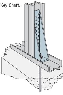
69 Page 69 of 81


70 The use of threaded rod or stainless steel cable to connect the top plate to the foundation; this can be used for single or multi-story structures. Threaded rod installed from footing though top plate in two story house. Stainless Steel cable installed for up-lift resistance in single story house. Page 70 of 81


71 Sheathing used for uplift transfer from top plate to bottom plate. Connectors from roof structure must be used to transfer uplift load to top plate, panels can then transfer the load to the bottom plate which is anchored to the floor/foundation. Page 71 of 81


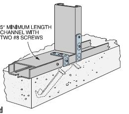

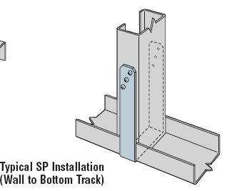

72 Page 72 of 81


, all exposed hardware, and fasteners must be stainless steel.")
73 Attached Structures: Securely anchor connections for exterior attached structures such as carports and porches that attach to the main structure of the house. Stainless steel or hot dipped galvanized hardware with a minimum rating of G185 shall be used for any connections that will be exposed to weathering in service. Fasteners used with such hardware shall consist of a similar metal to prevent accelerated corrosion. In Coastal A and V flood zones (Section 4), all exposed hardware, and fasteners must be stainless steel. Strapping top of porch column to supporting beam. Connection of column on porch to foundation with post anchor. Page 73 of 81

74 APPENDIX F FORTIFIED for Safer Living Seismic Zones Figure 1: FORTIFIED Seismic Zones of the contiguous U.S. (Alaska and Hawaii are also considered seismic zones) The following states in their entirety shall meet the seismic requirements of the FORTIFIED program: 1. Alaska 2. California 3. Hawaii 4. Nevada Page 74 of 81
75 In addition, the following counties within the states listed below must meet the requirements of the FORTIFIED program: Arizona Coconino Mohave Pima Yuma Arkansas Arkansas Clay Cleburne Craighead Crittenden Cross Faulkner Fulton Greene Independence Izard Jackson Lawrence Lee Lonoke Mississippi Monroe Phillips Poinsett Prairie Pulaski Randolph Sharp St. Francis Stone White Woodruff Illinois Alexander Bond Clay Clinton Crawford Edwards Effingham Fayette Franklin Gallatin Hamilton Hardin Jackson Jasper Jefferson Lawrence Madison Marion Massac Monroe Perry Pope Richland Saline St. Clair Union Wabash Washington Wayne White Randolph Williamson Indiana Gibson Knox Pike Posey Spencer Vanderburgh Warrick Kentucky Ballard Caldwell Calloway Carlisle Christian Crittenden Daviess Fulton Graves Henderson Hickman Hopkins Livingston Lyon Marshall McCracken McLean Muhlenberg Todd Trigg Union Webster Mississippi Benton Coahoma Desoto Lafayette Marshall Panola Quitman Tate Tippah Tunica Missouri Bollinger Butler Cape Girardeau Carter Madison Dunklin Iron Jefferson Madison Mississippi New Madrid Ripley Scott Shannon St. Francois St. Louis St.Genevieve Stoddard Washington Wyne Montana Beaverhead Broadwater Cascade Deer Lodge Flathead Gallatin Glacier Granite Jefferson Lake Lewis and Clark Park Pondera Powell Sanders Silver Bow Teton New Mexico Bernalillo Los Alamos Rio Arriba Sandoval Santa Fe Socorro Valencia New York Clinton Franklin St. Madison Lawrence Silver Bow North Carolina Cherokee Graham Swain Oregon Baker Benton Clackamas Clatsop Columbia Curry Coos Deschutes Douglas Harney Hood River Jackson Josephine Klamath Lake Lane Lincoln Linn Malheur Marion Multnomah Polk Tillamook Umatilla Wasco Washington Yamhill South Carolina Aiken Allendale Bamberg Barnwell Beaufort Berkeley Calhoun Charleston Chesterfield Clarendon Colleton Darlington Dillon Dorchester Fairfield Georgetown Hampton Horry Jasper Florence Kershaw Lee Lexington Orangeburg Richland Sumter Williamson Tennessee Anderson Benton Blount Bradley Chester Coclee Dillon Dorchester Carroll Crockett Decatur Dyer Fayette Grainger Gibson Hamblen Hamilton Hardeman Hardin Haywood Henderson Henry Houston Humphreys Lake Lauderdale Jefferson Knox Loudon Monroe Madison McNairy Montgomery Obion Polk Sevier Perry Shelby Stewart Tipton Union Weakley Utah Beaver Box Elder Cache Carbon Davis Duchesne Emery Garfield Iron Juab Kane Millard Morgan Piute Rich Salt Lake Sanpete Sevier Summit Tooele Utah Wasatch Washington Wayne Weber Washington Benton Chelan Clallam Clark Cowlitz Grays - Harbor Island Jefferson King Kitsap Kittitas Klickitat Lewis Mason Pacific Pierce San Juan Skagit Skamania Snohomish Thurston Wahkiakum Walla Walla Whatcom Yakima Wyoming Freemont Lincoln Park Sublette Teton Uinta Page 75 of 81

76 APPENDIX G FORTIFIED for Safer Living Example Foundation Reinforcement for Seismic Zones This appendix contains five illustrations, each of a different commonly used foundation system. The drawings and text show minimum reinforcement requirements for foundations of FORTIFIED structures built in areas defined by the FORTIFIED program as seismic risk zones. Note: each illustration contains a title that describes what type of system it is. An elevation (left) and a profile (right) are shown for each system. Page 76 of 81


77 Page 77 of 81


78 Page 78 of 81
REINFORCING TABLES INSTALLATION MANUAL
 REINFORCING TABLES 201 REINFORCING TABLES Design Limitations Introduction The structural wall reinforcing and lintel design tables contained within the Appendix of NUDURA s Installation Manual have been
4. REFERENCE STANDARDS AND GUIDANCE DOCUMENTS CONTACT INFORMATION... 44
 Volume I: Standards VOLUME I CONTENTS 1 INTRODUCTION... 1 1.1 Natural hazards addressed by FORTIFIED for Safer Business Standards:... 1 1.2 Building Code Requirements... 2 1.3 Statement of Land Use Policy...
Revised Standards. A program of the Insurance. FORTIFIED is a program of the Insurance Institute for Business & Home Safety. Volume I: Standards
 Revised 2014 Standards A program of the Insurance FORTIFIED is a program of the Insurance Institute for Business & Home Safety Volume I: Standards VOLUME I CONTENTS 1 INTRODUCTION... 1 1.1 Natural hazards
This public resource is maintained by Smart Home America and is available at: SmartHomeAmerica.org/resources/details/code-supplement
 The Coastal Construction Code Supplement was created and adopted by community leaders and Building Code Officials in Coastal Alabama, in partnership with Smart Home America, after being impacted by both
FORTIFIED Home High Wind. Bronze New Roof Requirements
 THE DECK (PREP MATERIAL, FASTENING) THE ROOF DECK SEALING THE ROOF DECK All existing roof cover and flashings shall be removed; deck shall be a clean, workable surface free from debris. Damaged or rotten
Why FORTIFIED? Tier 1: FORTIFIED Bronze. FORTIFIED Silver. Tier 2: FORTIFIED Gold
 The goal of the FORTIFIED for Existing Homes program is to strengthen your home against specific regional natural hazards through a retrofitting process. Depending on the natural hazard, the program may
Protecting YOUR EXISTING HOME FROM Wind Damage
 Protecting YOUR EXISTING HOME FROM Wind Damage Blueprint for Safety... A Blueprint for Life When severe weather threatens, protecting life and property automatically becomes top priority for millions of
RESIDENTIAL RE-ROOFING PERMIT APPLICATION
 RESIDENTIAL RE-ROOFING PERMIT APPLICATION Effective date: October 1, 2007. Note: These requirements apply to residential structures built prior to implementation of the FBC on March 1, 2002. I. LEGAL DESCRIPTION:
Hurricane- Resistance. designations: WHY FORTIFIED? DESIGNATION PROCESS
 Hurricane- Resistance Designation The goal of the FORTIFIED for Existing Homes program is to strengthen your home against specific regional natural hazards through a retrofitting process. Depending on
Christopher North Builders INC
 Christopher North Builders INC Naples, Florida 239-825-9155 chrisnorthnaples@gmail.com Inspection Date: Uniform Mitigation Verification Inspection Form Maintain a copy of this form and any documentation
Uniform Mitigation Verification Inspection Form Maintain a copy of this form and any documentation provided with the insurance policy
 Inspection Date: Uniform Mitigation Verification Inspection Form Maintain a copy of this form and any documentation provided with the insurance policy Owner Information Owner Name: Contact Person: Address:
Owner Information. Inspection Date:
 Draft Proposed Near-Term Changes for OIR Review Applied Research Associates, F. Lavelle, 5/27/11 Uniform Mitigation Verification Inspection Form Maintain a copy of this form with the insurance policy Inspection
Builders, Realtors, Roofers and Yourself
 What to Ask Builders, Realtors, Roofers and Yourself About Protecting Your Home from Hurricanes, High Winds and Hail. Texas Department of Insurance Asking the following questions will help protect your
Uniform Mitigation Verification Inspection Form Maintain a copy of this form with the insurance policy
 Inspection Date: Owner Information Owner Name: Address: Uniform Mitigation Verification Inspection Form Maintain a copy of this form with the insurance policy Contact Person: Home Phone: City: Zip: Work
Christopher North Builders, INC.
 Christopher North Builders, INC. 239-825-9155 Naples, Florida 34108 chrisnorthnaples@gmail.com Inspection Date: Uniform Mitigation Verification Inspection Form Maintain a copy of this form and any documentation
DATE:6/18/2013 INSPECTOR: ELEVATION
 DATE:6/18/2013 INSPECTOR: C ELEVATION DATE:6/18/2013 ROOF DECK ATTACHMENT ROOF TO WALL OPENING PROTECTION NA DOCUMENTS/ PERMITS, TITUSVILLE 32780 Permit #12-768 Applied: 5.14.12 Issued: 5.14.12 Final:
Uniform Mitigation Verification Inspection Form Maintain a copy of this form and any documentation provided with the insurance policy
 Inspection Date: Uniform Mitigation Verification Inspection Form Maintain a copy of this form and any documentation provided with the insurance policy Jul 16, 2012 Owner Information Owner Name: John Miller
Uniform Mitigation Verification Inspection Form Maintain a copy of this form and any documentation provided with the insurance policy
 Inspection Date: 12/07/2018 Uniform Mitigation Verification Inspection Form Maintain a copy of this form and any documentation provided with the insurance policy Owner Information Owner Name: The Oaks
Go Green Thermal Imaging, LLC P.O. Box 1523 Hobe Sound, FL Phone: GGTI (4484)
") Go Green Thermal Imaging, LLC P.O. Box 1523 Hobe Sound, FL 33475 Phone: 888-984-GGTI (4484) E-mail:CPlaia@GGTISolutions.com Wind Mitigation Walt Leary 637 NE 12th Ter, Unit 7 Boynton Beach, FL 33435 September
Go Green Thermal Imaging, LLC P.O. Box 1523 Hobe Sound, FL 33475 Phone: 888-984-GGTI (4484) E-mail:CPlaia@GGTISolutions.com Wind Mitigation Walt Leary 637 NE 12th Ter, Unit 7 Boynton Beach, FL 33435 September
Uniform Mitigation Verification Inspection Form Maintain a copy of this form and any documentation provided with the insurance policy
 Inspection Date: 05/24/2017 Uniform Mitigation Verification Inspection Form Maintain a copy of this form and any documentation provided with the insurance policy Owner Information Owner Name: Banana Bay
Uniform Mitigation Verification Inspection Form Maintain a copy of this form with the insurance policy
 Inspection Date: Owner Information Owner Name: Address: Uniform Mitigation Verification Inspection Form Maintain a copy of this form with the insurance policy Contact Person: City: Jupiter Zip: 33458 Work
Uniform Mitigation Verification Inspection Form Maintain a copy of this form and any documentation provided with the insurance policy
 Uniform Mitigation Verification Inspection Form Maintain a copy of this form and any documentation provided with the insurance policy Inspection Date: 04/01/2015 Owner Information Owner Name: JACK AND
Uniform Mitigation Verification Inspection Form Maintain a copy of this form with the insurance policy
 Inspection Date: Owner Information Owner Name: Address: Uniform Mitigation Verification Inspection Form Maintain a copy of this form with the insurance policy Contact Person: Home Phone: City: Zip: Work
Uniform Mitigation Verification Inspection Form Maintain a copy of this form with insurance policy
 Uniform Mitigation Verification Inspection Form Maintain a copy of this form with insurance policy Inspection Date: 08/12/2011 Owner Information Owner Name: Steve Owner Contact Person: Joe Contact Address:
1. Asphalt / Fiberglass Shingle / / 2. Concrete / Clay Tile 05_/_01 /_ Metal / / 4. Built Up / / 5. Membrane / / 6.
 Uniform Mitigation Verification Inspection Form Maintain a copy of this form and any documentation with the insurance policy Inspection Date: 14-Aug-14 Owner Information Owner Name: Contact Person: Brett
Go Green Thermal Imaging, LLC P.O. Box 1523 Hobe Sound, FL Phone: GGTI (4484)
") Go Green Thermal Imaging, LLC P.O. Box 1523 Hobe Sound, FL 33475 Phone: 888-984-GGTI (4484) E-mail:CPlaia@GGTISolutions.com Wind Mitigation Richard & Andrea Freedman 182 Eagle Dr. Jupiter, FL 33477 March
Go Green Thermal Imaging, LLC P.O. Box 1523 Hobe Sound, FL 33475 Phone: 888-984-GGTI (4484) E-mail:CPlaia@GGTISolutions.com Wind Mitigation Richard & Andrea Freedman 182 Eagle Dr. Jupiter, FL 33477 March
Page Roof Covering Type: Permit Application Date FBC or MDC Product Approval #
 Uniform Mitigation Verification Inspection Form Maintain a copy of this form and any documentation provided with the insurance policy Inspection Date: 1/5/2013 Owner Information Owner Name: Sinha Contact
Carroll County Bureau of Permits and Inspection Residential Code Compliance Guidelines Detached Garage
 Carroll County Bureau of Permits and Inspection Residential Code Compliance Guidelines Detached Garage The following list of code requirements is intended to assist you in complying with the Code of Public
COMMERCIAL WINDSTORM MITIGATION INSPECTION REPORT Prepared for: Boca Vista Condominium Association, Inc th Avenue Madeira Beach, FL 33708
 Insurance Appraisals Reserve Studies Wind Mitigation COMMERCIAL WINDSTORM MITIGATION INSPECTION REPORT Prepared for: Boca Vista Condominium Association, Inc. 401 150th Avenue Madeira Beach, FL 33708 As
TEXAS RESIDENTIAL ROOFS
 INSURANCE INSTITUTE FOR BUSINESS & HOME SAFETY BEST PRACTICES GUIDE Use this guidance to improve the long-term performance of your rf. In the spring of 2016, severe storms ripped through Texas, substantially
City of Republic Community Development Department. Residential Roofs REVISION DATE: JANUARY 2017
 City of Republic Community Development Department Residential Roofs REVISION DATE: JANUARY 2017 A residential roof permit is required for new roofs and for replacement roofs when the replacement area is
ACCESSORY STRUCTURE Building permit information For 1 & 2-family dwellings
 ACCESSORY STRUCTURE Building permit information For 1 & 2-family dwellings Building Safety Department 400-2 nd Street South St. Cloud, MN 56301 (320) 255-7239 A building permit is required for any accessory
The better way to build TM. Installation Manual NAILBASE PANELS
 The better way to build TM Installation Manual PANELS November 2018 SIPs Installation Manual Table of Contents Topics General Requirements................................... 3 Materials..............................................
16.4 FLORIDA BUILDING CODE BUILDING
 1604.8-1606.1.2 5. Designs using NAAMM FP-1001 Specification for Design Loads of Metal Flagpoles. 6. Subject to the limitations of 1606.1.1.1, 1606.1.4, and 1606.1.6, the provisions of the FC&PA Guide
SUBJECT: NEW 2000 INTERNATIONAL RESIDENTIAL CODE (IRC) DATE:
 DATE:") IRC CODE UPDATES TO: RESIDENTIAL BUILDING CONTRACTORS FROM: GARY STABER, BUILDING OFFICIAL SUBJECT: NEW 2000 INTERNATIONAL RESIDENTIAL CODE (IRC) DATE: 6/1/2003 INTERNATIONAL RESIDENTIAL CODE (IRC) APPLICABILITY:
IRC CODE UPDATES TO: RESIDENTIAL BUILDING CONTRACTORS FROM: GARY STABER, BUILDING OFFICIAL SUBJECT: NEW 2000 INTERNATIONAL RESIDENTIAL CODE (IRC) DATE: 6/1/2003 INTERNATIONAL RESIDENTIAL CODE (IRC) APPLICABILITY:
Insulation. First Revison October DC14 Drainage Mat INSTALLATION GUIDE FOR RESIDENTIAL & COMMERCIAL APPLICATIONS
 Insulation First Revison October 2016 DC14 Drainage Mat INSTALLATION GUIDE FOR RESIDENTIAL & COMMERCIAL APPLICATIONS 1. General Information This Guide describes the use of Kingspan GreenGuard DC14 Drainage
Stone and Masonry Veneer
 Stone and Masonry Veneer R703.7 Stone and masonry veneer, general. Stone and masonry veneer shall be installed in accordance with this chapter, Table R703.4 and Figure R703.7. These veneers installed over
The Loss Mitigation Grant Program Grants for Home Retrofits using Wind Resistive Devices Saturday June 2, 2007
 The Loss Mitigation Grant Program Grants for Home Retrofits using Wind Resistive Devices Saturday June 2, 2007 OUTLINE Introduction to the Loss Mitigation Grant Program Hurricane Probabilities in Hawaii
Garage/Accessory Structures
 Garage/Accessory Structures City of New Prague Building Inspections Department 118 Central Ave N New Prague, MN 56071 (952) 758-4401 Fax (952) 758-1149 Requirements for submitted Building Plans Signed
A PROGRAM OF IBHS COMMERCIAL
 A PROGRAM OF IBHS COMMERCIAL HURRICANE NEW CONSTRUCTION PROJECT DESIGN FORM & COMPLIANCE CHECKLIST 2017 FORTIFIED Commercial Hurricane Resources and Documentation FORTIFIED Commercial Hurricane Standards
Exterior Brick Masonry Veneer Supported by Metal Plate Connected Wood Trusses (MPCWT) Overview Revised 11/17/2016
 Overview Revised 11/17/2016") Exterior Brick Masonry Veneer Supported by Metal Plate Connected Wood Trusses (MPCWT) Overview Revised 11/17/2016 SBCA has been the voice of the structural building components industry since 1983, providing
Exterior Brick Masonry Veneer Supported by Metal Plate Connected Wood Trusses (MPCWT) Overview Revised 11/17/2016 SBCA has been the voice of the structural building components industry since 1983, providing
ROOF MITIGATION STRUCTURE EVALUATION FORM. For Single Family Residential Re-Roof Effective October 1, 2007 (Revised February 2, 2018)
") ROOF MITIGATION STRUCTURE EVALUATION FORM For Single Family Residential Re-Roof Effective October 1, 2007 (Revised February 2, 2018) Check One Value of home does not exceed $300,000 based on insured value
ROOF MITIGATION STRUCTURE EVALUATION FORM For Single Family Residential Re-Roof Effective October 1, 2007 (Revised February 2, 2018) Check One Value of home does not exceed $300,000 based on insured value
Details for Exterior Brick Masonry Veneer Supported by Metal Plate Connected Wood Trusses
 Details for Exterior Brick Masonry Veneer Supported by Metal Plate Connected Wood Trusses Released May 20, 2009 Updated March 9, 2011 Introduction: Wood frame structures with attached brick masonry veneer
4 Structural Performance
 Section 4 STRUCTURAL PERFORMANCE 4 Structural Performance The BPAT inspected the structural performance of three primary construction types: reinforced concrete, reinforced masonry, and wood-frame. Inspections
DESIGNING SAFE ROOMS AND SAFE HOMES WITH LOGIX.
 . Actual ICF-Built Home That Survived Katrina Table of Contents Section Page Overview Logix Wind Resistance Advantages...3 Logix Wall Engineering To 300 MPH Wind Rating...6 Fema-Compliant Design Specifications
Supplemental Plan Correction Sheet for LA Residential Code Prescriptive Design (2014 LARC)
") Supplemental Plan Correction Sheet for LA Residential Code Prescriptive Design (2014 LARC) Plan Check Submittal Date: Plan Check #: Permit App.# Job Address: Applicant: Phone: ( ) Plan Check Engineer:
Supplemental Plan Correction Sheet for LA Residential Code Prescriptive Design (2014 LARC) Plan Check Submittal Date: Plan Check #: Permit App.# Job Address: Applicant: Phone: ( ) Plan Check Engineer:
INSTALLING WATER-RESISTIVE BARRIERS & FLASHING
 INSTALLING WATER-RESISTIVE BARRIERS & FLASHING IN A TWO-LAYER STUCCO APPLICATION Fortifiber Building Systems Group provides this guide to assist installers by demonstrating a two-layer installation of
STRUCTURAL DESIGN CRITERIA
 CHAPTER 3 STRUCTURAL DESIGN CRITERIA SECTION 301 GENERAL 301.1 Scope. Loads and load combinations shall be determined in accordance with ASCE 7 unless otherwise noted. Structural elements of the storm
Supplemental Plan Correction Sheet for LA Residential Code Prescriptive Design (2011 LARC)
") Supplemental Plan Correction Sheet for LA Residential Code Prescriptive Design (2011 LARC) Plan Check Submittal Date: Plan Check #: Permit App.# Job Address: Applicant: Phone: ( ) P.C. Engineer: Phone:
Supplemental Plan Correction Sheet for LA Residential Code Prescriptive Design (2011 LARC) Plan Check Submittal Date: Plan Check #: Permit App.# Job Address: Applicant: Phone: ( ) P.C. Engineer: Phone:
IBHS Members-Only Data Report:
 IBHS Members-Only Data Report: Methodology of State Building Code Ratings December 31, 2011 In early January, the Insurance Institute for Business & Home Safety (IBHS) released the report, Rating the States:
COMMERCIAL WINDSTORM MITIGATION INSPECTION REPORT. Long Bayou Condominium Association, Inc.
 Insurance Appraisals Reserve Studies Wind Mitigation COMMERCIAL WINDSTORM MITIGATION INSPECTION REPORT Prepared for: Long Bayou Condominium Association, Inc. As of 4/10/2017 This report contains windstorm
WeatherSmart Air Barrier Installation Guide
 WeatherSmart Air Barrier Installation Guide 1 The intent of this document is to provide a guide for the installation of WeatherSmart as both a Weather Resistive Barrier (W.R.B.) and an Air Barrier Material
U.S. EDITION RESIDENTIAL CONSTRUCTION DETAILS SAMPLE. A visual guide to construction detailing. Emma Walshaw
 RESIDENTIAL CONSTRUCTION DETAILS U.S. EDITION A visual guide to construction detailing Emma Walshaw Contents INTRODUCTION 4 PRINCIPLES OF CONSTRUCTION DETAILING 6 FOUNDATIONS 9 PRINCIPLES OF FOUNDATION
Exterior Brick Masonry Veneer Supported by Metal Plate Connected Wood Trusses (MPCWT) Design Guide Revised 11/17/2016
 Design Guide Revised 11/17/2016") Exterior Brick Masonry Veneer Supported by Metal Plate Connected Wood Trusses (MPCWT) Design Guide Revised 11/17/2016 SBCA has been the voice of the structural building components industry since 1983,
Exterior Brick Masonry Veneer Supported by Metal Plate Connected Wood Trusses (MPCWT) Design Guide Revised 11/17/2016 SBCA has been the voice of the structural building components industry since 1983,
R Code and Commentary for 2012 NC Residential Code final 03/06/13
 R602.10 Code and Commentary for 2012 NC Residential Code final 03/06/13 Commentary italicized and printed in red 1. Section R602.10 -- provides charging language for two simplified bracing approaches (isolated
NCMA TEK RESIDENTIAL DETAILS FOR HIGH WIND AREAS. TEK 5-11 Details (2003)
") NCM TEK National Concrete Masonry ssociation an information series from the national authority on concrete masonry technology RESIDENTIL DETILS FOR HIGH WIND RES TEK 5-11 Details (2003) Keywords: architectural
NCM TEK National Concrete Masonry ssociation an information series from the national authority on concrete masonry technology RESIDENTIL DETILS FOR HIGH WIND RES TEK 5-11 Details (2003) Keywords: architectural
GARAGES/ONE-STORY City of Grand Rapids Building Safety Division
 GARAGES/ONE-STORY City of Grand Rapids Building Safety Division 218-326-7601 www.cityofgrandrapidsmn.com This handout is intended only as a guide and is based in part on the 2015 Minnesota State Building
Florida Building Code 6th Edition (2017) High-Velocity Hurricane Zone Uniform Permit Application Form
 High-Velocity Hurricane Zone Uniform Permit Application Form") Are there Gas Vent Stacks? Yes No Type: Natural LPGX FBC SECTION 1524 HIGH-VELOCITY HURRICANE ZONES REQUIRED OWNER S NOTIFICATION FOR ROOFING CONSIDERATIONS 1524.1 Scope. As it pertains to this section,
Are there Gas Vent Stacks? Yes No Type: Natural LPGX FBC SECTION 1524 HIGH-VELOCITY HURRICANE ZONES REQUIRED OWNER S NOTIFICATION FOR ROOFING CONSIDERATIONS 1524.1 Scope. As it pertains to this section,
Guide to Attaching Exterior Wall Coverings through Foam Sheathing to Wood or Steel Wall Framing
 Guide to Attaching Exterior Wall Coverings through Foam Sheathing to Wood or Wall Framing Released September 20, 2010 Updated December 4, 2012 Note: Tables for cladding attachments to wood framing have
A PROGRAM OF IBHS COMMERCIAL
 A PROGRAM OF IBHS COMMERCIAL HIGH WIND & HAIL NEW CONSTRUCTION PROJECT DESIGN FORM & COMPLIANCE CHECKLIST 2017 FORTIFIED Commercial High Wind & Hail Documentation FORTIFIED Commercial High Wind & Hail
ESR-2015P* Reissued April 2014 This report is subject to renewal April 1, 2015.
 ICC-ES Evaluation Report ESR-2015P* Reissued April 2014 This report is subject to renewal April 1, 2015. www.icc-es.org (800) 423-6587 (562) 699-0543 A Subsidiary of the International Code Council DIVISION:
HUMBOLDT COUNTY BUILDING & SAFETY DEPARTMENT CITY OF WINNEMUCCA BUILDING DEPARTMENT
 HUMBOLDT COUNTY BUILDING & SAFETY DEPARTMENT CITY OF WINNEMUCCA BUILDING DEPARTMENT FOR PRIVATE THREE-SIDED POST FRAMED (NON-ENGINEERED) OUTBUILDINGS LOCATED ON RESIDENTIAL LOTS ONLY Buildings must meet
CHAPTER 3 BUILDINGS WITH WOOD FRAMED EXTERIOR WALLS 301 SCOPE
 CHAPTER 3 BUILDINGS WITH WOOD FRAMED EXTERIOR WALLS WOOD CHAPTER 3 301 SCOPE This chapter prescribes construction requirements for buildings where all exterior walls above the foundation are wood framed
Benchmarking Standards, Model Codes, Codes and Voluntary Guidelines on the HERS Index
 Benchmarking Standards, Model Codes, Codes and Voluntary Guidelines on the HERS Index Importance of Benchmarking Quantifying energy efficiency programs and codes helps: Consumers understand the performance
DIVISION: THERMAL AND MOISTURE PROTECTION SECTION: METAL ROOF PANELS SECTION: METAL WALL PANELS REPORT HOLDER:
 0 Most Widely Accepted and Trusted ICC ES Evaluation Report ICC ES 000 (800) 4 6587 (562) 699 0543 www.icc es.org ESR 3152 Reissued 08/2017 This report is subject to renewal 08/2018. DIVISION: 07 00 00
DIVISION: THERMAL AND MOISTURE PROTECTION SECTION: COMPOSITE RUBBER SHAKES REPORT HOLDER: DAVINCI ROOFSCAPES, LLC
 0 Most Widely Accepted and Trusted ICC-ES Evaluation Report ICC-ES 000 (800) 423-6587 (562) 699-0543 www.icc-es.org ESR-2119 Reissued 08/2017 This report is subject to renewal 08/2019. DIVISION: 07 00
Table 3. Detailed Comparison of Structural Provisions of IRC 2000 and 1997 NEHRP (Continued)
") 2000 IRC 1997 NEHRP Section Provision Section Provision Comments CHAPTER 3 BUILDING PLANNING R301 DESIGN CRITERIA R301.2.2 Seismic Provisions R301.2.2.1 Determination of Seismic Design Category R301.2.2.1.1
2000 IRC 1997 NEHRP Section Provision Section Provision Comments CHAPTER 3 BUILDING PLANNING R301 DESIGN CRITERIA R301.2.2 Seismic Provisions R301.2.2.1 Determination of Seismic Design Category R301.2.2.1.1
ZARA & ASSOCIATES, INC. Peter L. Zara 8435 Sunrise Lake Blvd -# Sunrise, Florida Phone
 12 ZARA & ASSOCIATES, INC. Peter L. Zara 8435 Sunrise Lake Blvd -#43-307 Sunrise, Florida 33322 Phone 305-345-3793 E-Mail: peterizara@hotmail.com COURSE MATERIALS ROOFING COURSE WITH UPDATED MATERIALS
application instructions
 application instructions FOUNDATIONS 76 & 120 SERIES PRIMED PANEL SIDING ARCHITECTURAL COLLECTION REVERSE BOARD & BATTEN AND STUCCO PANEL SIDING General At the time of manufacture, siding meets or exceeds
TECHNICAL INFORMATION
 TECHNICAL INFORMATION SECTION 07320 TWO-PIECE TAPERED MISSION CLAY ROOFING TILE PART 1 GENERAL 1.01 SECTION INCLUDES A. Formed clay roofing tiles, complete with components and other required accessories
September 22, Applied Research Associates, Inc Six Forks Road, Suite 600 (919)
") Uniform Mitigation Verification Inspection Form: Issues and Recommendations September 22, 2010 Applied Research Associates, Inc. 8537 Six Forks Road, Suite 600 Raleigh, NC 27615 (919) 582-3350 Key Points
Uniform Mitigation Verification Inspection Form: Issues and Recommendations September 22, 2010 Applied Research Associates, Inc. 8537 Six Forks Road, Suite 600 Raleigh, NC 27615 (919) 582-3350 Key Points
Keri M. Rayborn Silver Rayborn Consultants P.O. Box 1565 Tallahassee, FL P F
 To: Subject: Cindy Walden RE: To Be Read Into the Record: Notice of Propose Rule Development regarding 690-170.0155 (OIR-B1-1802 "Uniform Mitigation Verification Inspection Form" From: Keri Rayborn [mailto:krayborn@earthlink.net]
GAF EnergyGuard Polyiso Wall Sheathing
 From: Technical Services May 15, 2013 GAF EnergyGuard Polyiso Wall Sheathing GAF s EnergyGuard Polyiso Wall Sheathing is intended to be installed on residential construction only. Application types include:
RESIDENTIAL DETACHED ACCESSORY STRUCTURES
 RESIDENTIAL DETACHED ACCESSORY STRUCTURES *A Building permit is required for any alteration or addition to any existing building or structure. MN State Building Code Section 1300.0120 Subpart 1 Permit
INTERNATIONAL ASSOCIATION OF PLUMBING AND MECHANICAL OFFICIALS UNIFORM EVALUATION SERVICES
 INTERNATIONAL ASSOCIATION OF PLUMBING AND MECHANICAL OFFICIALS UNIFORM EVALUATION SERVICES EVALUATION CRITERIA FOR ANCHORED MASONRY VENEER SYSTEM WITH POLYSTYRENE FOAM PLASTIC BACKING EC 021-2014 (Adopted
LP SmartSide Perfection Shingle
 Application Instructions Fiber Substrate Lap Siding A A - Lap Siding ON SITE STORAGE Store off the ground well supported, on a flat well-drained surface. (Diagram 1a) Additional support may be required
Versetta Stone Panelized Stone Veneer Applications Over Continuous Insulation. TER No Boral Stone Products LLC
 Applications Over Continuous Insulation TER No. 1212-01 Boral Stone Products LLC 200 Mansell Court East, Suite 310 Roswell, GA 30076 419-318-5345 949-341-8890 (fax) chris.hines@boral.com versettastone.com
STRUCTURAL DESIGN CRITERIA
 CHAPTER 3 STRUCTURAL DESIGN CRITERIA SECTION 301 GENERAL 301.1 Scope. Loads and load combinations shall be determined in accordance with ASCE 7 unless otherwise noted. Structural elements of the storm
City of Pembroke Pines 601 City Center Way, Pembroke Pines, FL Tel# Fax# Cover Sheet for Permits Submitted Online
 City of Pembroke Pines 601 City Center Way, Pembroke Pines, FL 33025 Tel#954-435-6502 Fax#954-435-6749 Cover Sheet for Permits Submitted Online All permits Submitted online Must include this completed
R-Matte Plus-3: Insulation for the Building Envelope
 Attic and Crawl Space Applications R-Matte Plus-3 may be applied to the interior face of stud walls or roof rafters within attics and crawl spaces to provide a layer of continuous insulation (ci). Simply
Pulaski County, Virginia Practical Wall Bracing
 Pulaski County, Virginia Practical Wall Bracing Based on the 2012 Virginia Residential Code The information herein provides guidelines for complying with the most common Practical Wall Bracing provisions
COMMERCIAL WINDSTORM MITIGATION INSPECTION REPORT Prepared for: Charlotte Bay Villas Association, Inc.
 Insurance Appraisals Reserve Studies Wind Mitigation COMMERCIAL WINDSTORM MITIGATION INSPECTION REPORT Prepared for: Charlotte Bay Villas Association, Inc. As of 2/16/2012 This report contains windstorm
HOW BIG IS AFRICA? Rules. recommended grades: 3-6
 AFRICA HOW BIG IS AFRICA? recommended grades: 3-6 time needed: 25 MINUTES Description Students develop a sense of scale by using their bodies and other tools to measure the length and width of Africa.
Asphalt Pavement Mix Production Survey On Reclaimed Asphalt Pavement, Reclaimed Asphalt Shingles, And Warm-mix Asphalt Usage:
 Asphalt Pavement Mix Production Survey On Reclaimed Asphalt Pavement, Reclaimed Asphalt Shingles, And Warm-mix Asphalt Usage: 2009-2010 Appendix A Purpose The National Asphalt Pavement Association is working
POST FRAME BUILDING STANDARDS
 CASS COUNTY, MISSOURI BUILDING CODES, ENVIRONMENTAL HEALTH AND ZONING DEPARTMENT 30508 S. West Outer Road, Harrisonville, MO 64701 P- (816) 380-8134 F- (816) 380-8130 POST FRAME BUILDING STANDARDS 201.3
Minimizing Water Intrusion Through Roof Vents in High-Wind Regions
 Minimizing Water Intrusion Through Roof Vents in High-Wind Regions http://www.fema.gov HURRICANE IKE RECOVERY ADVISORY Purpose: To recommend practices for minimizing water intrusion through roof vent systems
3 Assessment and Characterization of Damages
 3 Assessment and Characterization of Damages The general types of damages the BPAT observed as a result of Hurricane Georges in Puerto Rico are discussed below. More detailed descriptions of the damage
Updated Home Builder's Guide to Coastal Construction Technical Fact Sheets
 Updated Home Builder's Guide to Coastal Construction Technical Fact Sheets Manuel Perotin, PE, CFM Agenda Background & General Information New Fact Sheets & Guidance Resources FEMA Guidance/Publications
INTERNATIONAL ASSOCIATION OF PLUMBING AND MECHANICAL OFFICIALS UNIFORM EVALUATION SERVICE EVALUATION CRITERIA FOR
 INTERNATIONAL ASSOCIATION OF PLUMBING AND MECHANICAL OFFICIALS UNIFORM EVALUATION SERVICE EVALUATION CRITERIA FOR SINGLE SKIN STEEL ROOF AND WALL PANELS EC 011-2015 (Adopted - September 2013, Revision
EMERGENCY MANAGEMENT PREPAREDNESS AND ASSISTANCE TRUST FUND ARC 4496 Evaluation Questionnaire
 EMERGENCY MANAGEMENT PREPAREDNESS AND ASSISTANCE TRUST FUND ARC 4496 Evaluation Questionnaire Additional Instructions and Clarifications 1. Please review ARC 4496 before beginning the project identification
CONCRETE MASONRY VENEERS TEK 3-6C
 An information series from the national authority on concrete masonry technology CONCRETE MASONRY VENEERS TEK 3-6C Construction (2012) INTRODUCTION In addition to its structural use or as the exterior
Uniform Mitigation Verification Inspection Form Maintain a copy of this form and any documentation provided with the insurance policy Inspection Date:
 Uniform Mitigation Verification Inspection Form Maintain a copy of this form and any documentation provided with the insurance policy Inspection Date: 4/11/2017 Owner Information Owner Name: Plaza De Flores
GARAGE MAIN FLOOR PLAN
 BUILDING CONTRACTOR/HOME OWNER TO REVIEW AND VERIFY ALL DIMENSIONS, SPECS, AND CONNECTIONS BEFORE CONSTRUCTION BEGINS. SHED TO BE BUILT AS PER IRC, UBC OR CURRENT LOCAL CODE To the best of my knowledge
INSPECTION GUIDELINES: STRUCTURAL INSULATED PANELS (SIPs)
") Structural Insulated Panels Page 1 of 7 Revision Date: 05/22/2017 DEVELOPMENT SERVICES BUILDING INSPECTION INSPECTION GUIDELINES: STRUCTURAL INSULATED PANELS (SIPs) INSPECTION CODE: 111, 204, 216 SCOPE:
Structural Insulated Panels Page 1 of 7 Revision Date: 05/22/2017 DEVELOPMENT SERVICES BUILDING INSPECTION INSPECTION GUIDELINES: STRUCTURAL INSULATED PANELS (SIPs) INSPECTION CODE: 111, 204, 216 SCOPE:
ROOFING APPLICATION STANDARD (RAS) No. 118 INSTALLATION OF MECHANICALLY FASTENED ROOF TILE SYSTEMS Direct Deck & Counter Battens Only
 No. 118 INSTALLATION OF MECHANICALLY FASTENED ROOF TILE SYSTEMS Direct Deck & Counter Battens Only") ROOFING APPLICATION STANDARD (RAS) No. 118 INSTALLATION OF MECHANICALLY FASTENED ROOF TILE SYSTEMS Direct Deck & Counter Battens Only 1. 2. Scope This application standard covers the procedures for installation
ROOFING APPLICATION STANDARD (RAS) No. 118 INSTALLATION OF MECHANICALLY FASTENED ROOF TILE SYSTEMS Direct Deck & Counter Battens Only 1. 2. Scope This application standard covers the procedures for installation
GARAGE MAIN FLOOR PLAN
 BUILDING CONTRACTOR/HOME OWNER TO REVIEW AND VERIFY ALL DIMENSIONS, SPECS, AND CONNECTIONS BEFORE CONSTRUCTION BEGINS. SHED TO BE BUILT AS PER IRC, UBC OR CURRENT LOCAL CODE To the best of my knowledge
Department of Public Safety and Corrections Uniform Construction Code Council. Uniform Construction Code (LAC 55:VI.301)
") Department of Public Safety and Corrections Uniform Construction Code Council Uniform Construction Code (LAC 55:VI.301) In accordance with the provisions of R.S. 40:1730.26 and R.S. 40:1730.28, relative
Department of Public Safety and Corrections Uniform Construction Code Council Uniform Construction Code (LAC 55:VI.301) In accordance with the provisions of R.S. 40:1730.26 and R.S. 40:1730.28, relative
Residential Building Inspections
 Residential Building Inspections Foundations, Grade Beams, Pile Caps, Foundation Pads 1. All trenches or excavations and formwork shall be in accordance with the size(s) and configuration(s) as per approved
Administrative Changes
 Revised 11/29/06 Knox County Residential Building Codes Significant Changes From The 1995 CABO One And Two Family Dwelling Code To The 2006 International Residential Code All one and two family dwellings