Apparent Coefficient of Friction, f* to be Used in the Design of Reinforced Earth Structures. Technical Bulletin: MSE - 6
|
|
|
- Garry Gibbs
- 6 years ago
- Views:
Transcription
1 The Reinforced Earth Company 8614 Westwood Center Drive Suite 1100 Vienna, Virginia Telephone: (703) Telefax: (703) Apparent Coefficient of Friction, f* to be Used in the Design of Reinforced Earth Structures Technical Bulletin: MSE - 6 October 1995 Atlanta Boston Dallas/Ft. Worth Irvine, CA Lafayette, IN Orlando Seattle Vienna, VA
2 TABLE OF CONTENTS Page No. I. Introduction... 1 II. f* Used in the Design of Reinforced Earth Structures... 1 III. Discussion of the Influence of Water on the f* Value Used in Design IV. Influence of the Use of Uniform Fine Sands for Wall Backfill on the Apparent Coefficient of Friction, f* LIST OF FIGURES LIST OF TABLES
3 LIST OF FIGURES Figure 1: Values of Apparent Coefficient of Friction (f*) From Pullout Tests Figure 2: Apparent Coefficient of Friction, f o * in Relationship to the Coefficient of Uniformity, C u Figure 3: Gradation Curves and Determination of the Coefficient of Uniformity, C u, for Pullout Test Soils Figure 4: Apparent Coefficient of Friction, f*, at Optimum Moisture and in a Saturated Condition Figure 5: Apparent Coefficient of Friction, f*, in Uniform Fine Sand LIST OF TABLES Table 1: Direct shear Properties of Soils at Optimum Moisture and in a Saturated Condition
4 I. Introduction The topic of sliding shear resistance between galvanized steel reinforcing strips and soil has been the subject of numerous research studies in several countries. These studies have produced abundant data that, on first examination, are difficult to explain but will, after more detailed scrutiny, generally yield to the usual concepts of the shear strength properties of granular materials and sliding friction between materials. Several types of tests have been used to measure the apparent coefficient of friction, f*, between the soil and reinforcing material. These include: 1. Direct shear (sliding shear) tests between soil and reinforcing material. 2. Reinforcing strip pullout tests from a pullout test apparatus. 3. Reinforcing strip pullout tests from Reinforced Earth walls - model scale, prototype, and full scale structures. Of all the testing procedures used, the direct pullout test from a pullout test apparatus in the laboratory is the one most available to practicing engineers for the evaluation of design parameters. Other testing procedures require more specialized equipment, and generally involve higher cost which may not be justified by either the size of the project or the economic gain that may result from more refined data. Therefore, from a designer's standpoint, it is important to base the apparent coefficient of friction, f* on the abundant data that is available in the literature. II. f* Used in the Design of Reinforced Earth Structures All parameters assumed for the design of Reinforced Earth structures are conservatively taken as minimum values by enveloping the abundant data available in the literature. The available data, summarized in Figure 1 (the same figure referenced in the commentary of the 1994 AASHTO Standard Specifications for Highway Bridges Section C5.8.5) presents a summary of pullout test results for ribbed reinforcing strips in a variety of backfill materials ranging from silty sands to coarse gravels. Note that the f* envelope extending from a maximum value of 2.0 at the ground surface, to a minimum value of tan at a depth of 6 meters envelopes the data. As discussed in Section of the 1994 AASHTO standard specifications for highway bridges, a value of 2.0 may be used in the design of Reinforced Earth structures. 1
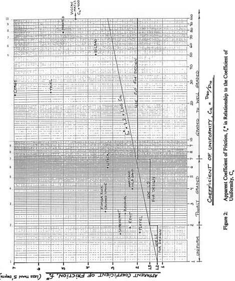
5 In the actual design of a Reinforced Earth wall, the value of the apparent coefficient of friction at the ground surface, f o *, is based on one of the following: 1. The backfill source for the project is known prior to design, therefore a value is selected that is appropriate for the backfill material to be used. 2. The backfill source is unknown, however, backfills used on previous projects have been consistent, or, the specified backfill gradation is restrictive in that it insures a certain type of backfill material. In either case, a reasonably representative value of f o * can be confidently selected. 3. Backfill sources local to the project are limited, such as uniform sands in Florida, such that an appropriate value of f o * can be assigned for the region. 4. The backfill source in unknown and the specified gradation is not very restrictive. A value of 1.5 is used in the design, and then checked once the gradation of the backfill is known. In addition, it is important to note that a minimum factor of safety of 1.5 with respect to reinforcement adherence is provided by design to cover any uncertainties associated with the value selected for f o * and for the resulting soil-reinforcement bond safety of the structure. Selection of f o * will depend on the coefficient of uniformity, C u, of the soil and on the angularity of the material (in the case of gravel). The coefficient of uniformity, C u, is equal to the size of the sieve opening through which 60 percent of the material passes, divided by the size of the sieve opening through which 10 percent of the material passes (D 60 /D 10 ). Generally if more than 10 percent of the material passes the #200 sieve, the #200 sieve opening (75µm) is used for the denominator. Figure 2 presents a summary of f o * values from project specific pullout tests. Note that the equation f o * = log C u (referenced in the literature) is well below all of the data points. Using this equation, the f o * value can be conservatively computed for use in design. For simplicity, three specific values of f o * are generally, but not exclusively, used in a design, depending on soil type: f o * = 1.2 f o * = 1.2 is to be used for projects constructed with backfills having a coefficient of uniformity Cu < 2, i.e., materials such as uniform fine sands, uniform medium sands, and uniform rounded 2
6 coarse materials such as pea gravel, unless substantiated otherwise by pullout tests in a representative backfill. f o * = 1.5 f o * = 1.5 is to be used for most projects constructed with backfills having a coefficient of uniformity 2 Cu < 7 (i.e., poorly graded sands, poorly graded river run gravels, and sand containing up to 25% passing the #200 sieve). Note, AASHTO specifications restrict fines to not more than 15% for all reinforced soil structures. f o * = 2.0 f o * = 2.0 is to be used for projects constructed with well graded backfills having a coefficient of uniformity Cu 7, or when using coarse well-graded angular materials, such as crusher run materials or poorly graded angular gravels. III. Discussion of the Influence of Water on the f* Valve Used in Design Hundreds of Reinforced Earth structures have become fully saturated in service or remain permanently inundated throughout the service life of the structure. There is not a significant reduction in the friction developed between the reinforcements and the saturated soil for backfills meeting the strict gradation requirements for Mechanically Stabilized Earth (MSE) backfill. The excellent performance of saturated MSE structures is due to the following: a. The soils specified for construction are granular and are of high shear strength, generally > 36, yet 34 shear strength is typically used in design. b. The soils are compacted during construction to relatively high densities while at or slightly dry of optimum moisture content. c. The soils are subjected to low strain levels in service and are normally stressed in plane strain. d. There is no mechanism for excess pore pressures to develop because of the use of reasonably free draining backfills. 3
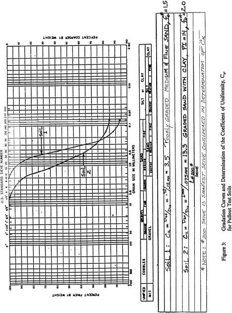
7 The following AASHTO requirements assure that the frictional characteristics of the soil, and, therefore, the apparent coefficient of friction between the soil and reinforcements, will remain essentially unaffected by saturation. a. 0-15% passing the number 200 sieve (restricts the percentage of silt and clay particles in the soil and thus ensures a material that is relatively free draining). b. A minimum shear strength of 34 determined by direct shear tests on a sample of material compacted to 95% of standard proctor density at optimum moisture content. c. Plasticity index less than or equal to six (restricts the percentage of plastic clay particles). Soils meeting these restrictive requirements, in addition to the required particle durability testing, will not be susceptible to a significant reduction in shear strength when becoming fully saturated. Of course, the same holds true for the apparent coefficient of friction, f*, between the strip and soil, since this parameter is directly related to the shear strength of the soil. In 1982, Terre Armee Internationale researched the effects of saturated conditions on the shear strength of soils and on the apparent coefficient of friction, f*. One of the soils studied meets all of the requirements specified by AASHTO for MSE structures. A second soil meets all of the AASHTO requirements except that the plasticity index is high and the material is borderline with respect to the percent passing the #200 sieve (75 µm). The results of these tests are presented herein as follows: a. Table 1 presents index properties and direct shear results for each soil at both optimum moisture content and in a saturated, undrained condition. b. Figure 3 presents, for each soil, a gradation curve and the determination of the coefficient of uniformity, C u, and the corresponding f o * value (from Figure 2) to be used in design. c. Figure 4 presents a plot of the apparent coefficient of friction determined by pullout tests at various heights of overburden for both optimum moisture and saturated conditions. In addition, the f* envelope that would be used for design, based on the material's gradation, is also shown. When a soil sample is sheared under poorly drained conditions, the resulting shear strength is generally less than that obtained under well drained conditions. However, for soils meeting 4
8 AASHTO MSE backfill specifications, the decrease in shear strength is not significant. Although the apparent coefficient of friction decreases due to saturation, the reduced values remain well above the envelope used for design. In addition, in the design of structures that become submerged, the forces to be resisted generally include the effects of a minimum 3 foot drawdown (differential head). In the reinforcing strip resistance calculation, reduced overburden on the reinforcing strips due to soil buoyancy is also included. Therefore, the influence of water in a saturated structure is already addressed in the design. There is no adjustment necessary of the f o * value used in the design. IV. Influence of the use of uniform fine sands for wall backfill on the apparent coefficient of friction, f* Available research demonstrates that the equation f o * = Log C u is conservatively representative of the f o * value that should be used for design when using uniform materials for backfill. Florida DOT launched an extensive research program to study the use of uniform fine sands in the construction of MSE walls. Uniform beach sand with a fine to medium grain size is the predominant backfill material available in Florida to construct MSE walls. One portion of the research program consisted of reinforcement pullout testing in beach sand to study the apparent coefficient of friction, f*, for ribbed reinforcing strips. Figure 5, enclosed is from a paper written by two Florida DOT engineers on the results of this research. The paper is not published, however, it is available from Florida DOT or The Reinforced Earth Company. Note that all of the pullout test results can be conservatively enveloped by a line used for design of Reinforced Earth structures in Florida. The design envelope originating from f o * = 1.5 at the ground surface, decreasing to tan 30 at a 20 foot depth is a conservative envelope despite the backfill material having a coefficient of uniformity just less than 2.0. In fact, f* values between 2.0 and 2.5 were determined near the top of the structure in the pullout tests. This testing demonstrates that the equation f o * = log C u is conservative, even in the case of very uniform materials with a coefficient of uniformity less than 2.0. The results of similar studies on materials with a coefficient of uniformity less than 2 are shown in Figure 2. Clearly, the f o * values are greater than log C u in every case. C:\wp51\pla\techbull\techbul6.doc 5
9
10
11
12
13
14 Table 1: Direct shear Properties of Soils at Optimum Moisture and in a Saturated Condition. Soil 1 Soil 2 Percent Passing #200 Sieve (i.e., silt 6% 15% and clay) Percent Finer than 15 µm 4% 12% (i.e., clay) Plasticity Index, PI Non-Plastic 14 * Direct Shear Test on Soil at Optimum Moisture Content **, Phi Angle Shear Test on Soil Saturated and Consolidated under 4000 psf * PI greater than AASHTO limit of 6 ** All shear tests performed under fast shearing conditions (1mm/min) Soil 1: Soil 2: Clean poorly graded sand Sand with some clay
SPECIFICATIONS FOR PRECAST MODULAR BLOCK RETAINING WALL SYSTEM (revised 5/8/7)
") Page 1 of 7 STONE STRONG SYSTEMS SPECIFICATIONS FOR PRECAST MODULAR BLOCK RETAINING WALL SYSTEM (revised 5/8/7) PART 1: GENERAL 1.01 Description A. Work includes furnishing and installing precast modular
Page 1 of 7 STONE STRONG SYSTEMS SPECIFICATIONS FOR PRECAST MODULAR BLOCK RETAINING WALL SYSTEM (revised 5/8/7) PART 1: GENERAL 1.01 Description A. Work includes furnishing and installing precast modular
SOIL MECHANICS Assignment #2: Soil Classification Solution.
 Geotechnical Engineering Research Laboratory One University Avenue Lowell, Massachusetts 01854 Edward L. Hajduk, D.Eng, PE Lecturer PA105D Tel: (978) 934 2621 Fax: (978) 934 3052 e mail: Edward_Hajduk@uml.edu
PD - 6 THRUST RESTRAINT DESIGN EQUATIONS AND SOIL PARAMETERS FOR DUCTILE IRON AND PVC PIPE
 PD - 6 THRUST RESTRAINT DESIGN EQUATIONS AND SOIL PARAMETERS FOR DUCTILE IRON AND PVC PIPE 4 3 2 1 D D C C B B A A 4 3 2 1 Thrust Restraint Design Equations and Soil Parameters These equations and soil
Engineering Properties of Foamed Recycled Glass as a Lightweight Fill
 Engineering Properties of Foamed Recycled Glass as a Lightweight Fill Robert H. Swan, Jr. 1, Seungcheol Yeom 2, Kurt J. Sjoblom, M. ASCE, Ph.D. 3, Timothy D. Stark, Fellow ASCE, Ph.D., P.E. 4 and Archie
SOIL CLASSIFICATION BASICS Commonly based on grain size and soil consistency. Several classification systems exist:
 SOIL CLASSIFICATION BASICS Commonly based on grain size and soil consistency. Several classification systems exist: 1. Unified System (USCS) (ASTM D2487-11). 2. American Association of State Highway and
Construction of MSE Wall Using Tire Shred-sand Mixture as Backfill (SPR-3470)
") Purdue University Purdue e-pubs JTRP Other Publications and Reports Joint Transportation Research Program 12-21-2011 Construction of MSE Wall Using Tire Shred-sand Mixture as Backfill (SPR-3470) Monica
Purdue University Purdue e-pubs JTRP Other Publications and Reports Joint Transportation Research Program 12-21-2011 Construction of MSE Wall Using Tire Shred-sand Mixture as Backfill (SPR-3470) Monica
PE Exam Review - Geotechnical
 PE Exam Review - Geotechnical Resources and Visual Aids Item Page I. Glossary... 11 II. Parameters... 9 III. Equations....11 IV. Tables, Charts & Diagrams... 14 1. Module 1 - Soil Classification... 14
t ghi yr Cop
 In many situations, soil itself is used as a construction material Highway embankments Railway embankments Earth dams Highway / Airfield pavements Backfilled trenches Landfills When soil is used as foundation
VERTI-BLOCK - DESIGN MANUAL
 Company Information General Information Verti-Block is the latest innovative forming system from Verti-Crete, LLC. Recognized worldwide for outstanding aesthetics and performance, Verti-Crete s proprietary
Characterizing Engineering Properties of Foundry Sands
 Characterizing Engineering Properties of Foundry Sands Craig H. Benson, PhD, PE Recycled Materials Resource Center University of Washington chbenson@u.washington.edu www.recycledmaterials.org Recycled
Design Data 6. Loads and Supporting Strengths Elliptical and Arch Pipe. Values of B d
 Design Data 6 Loads and Supporting Strengths Elliptical and Arch Pipe The hydraulic and structural characteristics of elliptical and arch shapes offer advantages, under certain conditions, over the circular
THE INFLUENCE OF FINES CONTENT AND PLASTICITY ON THE STRENGTH AND PERMEABILITY OF AGGREGATE FOR BASE COURSE MATERIAL
 THE INFLUENCE OF FINES CONTENT AND PLASTICITY ON THE STRENGTH AND PERMEABILITY OF AGGREGATE FOR BASE COURSE MATERIAL Bambang Ismanto SISWOSOEBROTHO Department of Civil Engineering Bandung Institute of
DESIGNING AND CONSTRUCTION OF T-WALL RETAINING WALL SYSTEM
 Istanbul Bridge Conference August 11-13, 2014 Istanbul, Turkey DESIGNING AND CONSTRUCTION OF T-WALL RETAINING WALL SYSTEM T. C. NEEL and K.BOZKURT ABSTRACT This work shall consist of the design, manufacture
SECTION AGGREGATES
 SECTION 32 05 00 AGGREGATES PART 1 GENERAL 1.01 SUMMARY A. Section Includes: 1. Aggregate base 2. Engineered fill 3. Backfill 4. Fine filter aggregate (non-frost susceptible fill) 5. Riprap 6. Recreational
Stability of a Mechanically Stabilized Earth Wall
 Stability of a Mechanically Stabilized Earth Wall GEO-SLOPE International Ltd. www.geo-slope.com 1400, 633-6th Ave SW, Calgary, AB, Canada T2P 2Y5 Main: +1 403 269 2002 Fax: +1 403 266 4851 Introduction
MSE WALLS CASE STUDIES. by John G. Delphia, P.E. TxDOT Bridge Division Geotechnical Branch
 MSE WALLS CASE STUDIES by John G. Delphia, P.E. TxDOT Bridge Division Geotechnical Branch COMMON RETAINING WALL TYPES CONCRETE BLOCK MSE TEMPORARY EARTH SPREAD FOOTING Gabions Drilled Shaft Soil Nail Tiedback
Shear Strength Improvement of Soft Clay Mixed with Tanjung Bin Coal Ash
 Available online at www.sciencedirect.com APCBEE Procedia 5 (2013 ) 116 122 ICESD 2013: January 19-20, Dubai, UAE Shear Strength Improvement of Soft Clay Mixed with Tanjung Bin Coal Ash Aminaton Marto
CE 240 Soil Mechanics & Foundations Lecture 3.3. Soil Compaction (Das, Ch. 5)
") CE 240 Soil Mechanics & Foundations Lecture 3.3 Soil Compaction (Das, Ch. 5) Class Outlines Soil compaction introduction Standard Proctor Compaction Test Effect of Compaction Energy Modified Proctor Compaction
CE 240 Soil Mechanics & Foundations Lecture 3.3 Soil Compaction (Das, Ch. 5) Class Outlines Soil compaction introduction Standard Proctor Compaction Test Effect of Compaction Energy Modified Proctor Compaction
CHAPTER 1 INTRODUCTION
 CHAPTER 1 INTRODUCTION During the early 1960s, the Virginia Department of Transportation undertook a program to upgrade aggregate materials. The Department felt this was necessary since the highway construction
GEOTECHNICAL INVESTIGATION I-15 SIGN BRIDGES LAS VEGAS EA JANUARY
 GEOTECHNICAL INVESTIGATION I-15 SIGN BRIDGES LAS VEGAS EA 73171 JANUARY 06 MATERIALS DIVISION STATE OF NEVADA DEPARTMENT OF TRANSPORTATION MATERIALS DIVISION GEOTECHNICAL SECTION GEOTECHNICAL REPORT I-15
Design Manual: Gravity Wall. Section 1
 Design Manual: Gravity Wall Section 1 A Design Manual: Gravity Wall General Information Company Information Verti-Block is the latest innovative forming system from Verti-Crete, LLC. Recognized worldwide
Word count: 3,975 words text + 11 tables/figures x 250 words (each) = 6,725 words Submission Date: August 1, 2016
 = 6,725 words Submission Date: August 1, 2016") Chaulagai, Osouli, Salam, Tutumluer, Beshears, Shoup, Bay 0 0 MAXIMUM PARTICLE SIZE, FINES CONTENT AND DUST RATIO INFLUENCING BEHAVIOR OF BASE AND SUBBASE COURSE AGGREGATES Rabindra Chaulagai Graduate
Chaulagai, Osouli, Salam, Tutumluer, Beshears, Shoup, Bay 0 0 MAXIMUM PARTICLE SIZE, FINES CONTENT AND DUST RATIO INFLUENCING BEHAVIOR OF BASE AND SUBBASE COURSE AGGREGATES Rabindra Chaulagai Graduate
INSPECTION GUIDE FOR SEGMENTAL RETAINING WALLS TEK 18-11B
 An information series from the national authority on concrete masonry technology INSPECTION GUIDE FOR SEGMENTAL RETAINING WALLS TEK 18-11B Quality Assurance and Testing (2012) INTRODUCTION Segmental retaining
Mix Design and Pumped Concrete
 Mix Design and Pumped Concrete A simple method of concrete mix design for pumpable concrete based on an estimated weight of the concrete per unit volume is described in the paper. The tables and figures
6. STABILIZED PAVEMENT MATERIALS
 6. STABILIZED PAVEMENT MATERIALS The term soil stabilisation may be defined as the alteration of the properties of an existing soil either by blending (mixing) two or more materials and improving particle
FE Review-Geotechnical 1. An undisturbed sample of clay has a wet mass of 100 kg. a dry mass of 93 kg, and a total volume of m'\ The solids
 1. An undisturbed sample of clay has a wet mass of 100 kg. a dry mass of 93 kg, and a total volume of 0.0491 m'\ The solids have a specific gravity of 2.65. The void ratio is most nearly (A) 0.31 (B) 0.40
UNDERSTANDING UNPAVED ROAD MATERIAL PERFORMANCE INTERPRETATION David Jones, PhD University of California Pavement Research Center
 UNDERSTANDING UNPAVED ROAD MATERIAL PERFORMANCE INTERPRETATION David Jones, PhD University of California Pavement Research Center Unpaved road performance is linked to material properties, road shape and
ANALYSIS & DESIGN OF 44 METER M.S.E. (MECHANICALLY STABILIZED EARTH) WALL BY USING PLAXIS 8.2
 WALL BY USING PLAXIS 8.2") Research Article ANALYSIS & DESIGN OF 44 METER M.S.E. (MECHANICALLY STABILIZED EARTH) WALL BY USING PLAXIS 8.2 1 D. Kishan, 2 Dr. N. Dindorkar, 3 Dr. R. Srivastava, 4* Ankesh Shrivastava Address for Correspondence
Research Article ANALYSIS & DESIGN OF 44 METER M.S.E. (MECHANICALLY STABILIZED EARTH) WALL BY USING PLAXIS 8.2 1 D. Kishan, 2 Dr. N. Dindorkar, 3 Dr. R. Srivastava, 4* Ankesh Shrivastava Address for Correspondence
Subsurface Investigations PDCA Professor s Driven Pile Institute. Loren R. Anderson Utah State University June 25, 2015
 Subsurface Investigations PDCA Professor s Driven Pile Institute Loren R. Anderson Utah State University June 25, 2015 Ralph B. Peck (1962) Subsurface engineering is an art; soil mechanics is an engineering
The Work under this Section consists of performing all operations necessary to complete construction of the leveling course on the prepared subbase.
 SECTION 20.22 LEVELING COURSE Article 22.1 General The Work under this Section consists of performing all operations necessary to complete construction of the leveling course on the prepared subbase. Article
GEOTECHNICAL REPORT B-1942
 GEOTECHNICAL REPORT TUSCARORA BRIDGE REPLACEMENT B-1942 E.A. 73561 March 2011 MATERIALS DIVISION STATE OF NEVADA DEPARTMENT OF TRANSPORTATION MATERIALS DIVISION GEOTECHNICAL SECTION GEOTECHNICAL REPORT
Redi Rock Specification and Installation Manual
 Redi Rock Specification and Installation Manual 1.0 General Scope This Specification covers the Design, Materials and Installation of Redi Rock modular block Retaining and Freestanding Wall systems as
Geoguide 6 The New Guide to Reinforced Fill Structure and Slope Design in Hong Kong
 Geoguide 6 The New Guide to Reinforced Fill Structure and Slope Design in Hong Kong Geotechnical Engineering Office Civil Engineering Department The Government of the Hong Kong Special Administrative Region
DETERMINATION OF THE LONG-TERM PROPERTIES FOR MIRAGRID XT GEOGRIDS
 DETERMINATION OF THE LONG-TERM PROPERTIES FOR MIRAGRID XT GEOGRIDS Prepared by: TenCate Geosynthetics Americas 365 South Holland Drive Pendergrass, GA 30567 Tel 706 693 2226 Fax 706 693 4400 www.tencate.com
Introduction to Foundations on Fill and Backfilling
 Introduction to Foundations on Fill and Backfilling Course No: G01-003 Credit: 1 PDH J. Paul Guyer, P.E., R.A., Fellow ASCE, Fellow AEI Continuing Education and Development, Inc. 9 Greyridge Farm Court
Standard Test Method for Torsional Ring Shear Test to Determine Drained Residual Shear Strength of Cohesive Soils 1
 Designation: D 6467 06 Standard Test Method for Torsional Ring Shear Test to Determine Drained Residual Shear Strength of Cohesive Soils 1 This standard is issued under the fixed designation D 6467; the
In preparation for constructing buildings on a property, the builder. Site Preparation CHAPTER
 CHAPTER 3 Site Preparation In preparation for constructing buildings on a property, the builder must consider a number of factors related to code requirements. The buildings must be located according to
Effect of Clay Content on Permeability and Compaction Parameters of Sand
 Effect of Clay Content on Permeability and Compaction Parameters of Sand Shahid Noor Scientist C, Central Soil and Materials Research Station Amardeep Singh Scientist C, Central Soil and Materials Research
Preview of LEAME Computer Software
 Appendix Preview of LEAME Computer Software Thus far, this book has focused on the fundamental principles and methods for analyzing slope stability using the limit equilibrium method. The computer software
Classification of Soils
 Classification of Soils Soils - What are they? Particulate materials - Sedimentary origins (usually) - Residual Wide range of particle sizes - larger particles: quartz, feldspar - very small particles:
Design Data 9. Standard Installations and Bedding Factors for the Indirect Design Method
 Design Data 9 Standard Installations and Bedding Factors for the Indirect Design Method Background The classic theory of earth loads on buried concrete pipe published, in 1930 by A. Marston, was developed
MECHANICALLY STABILIZED EARTH (MSE) WALL SYSTEMS
 WALL SYSTEMS") DRAINAGE SOLUTIONS SINCE 1908 MECHANICALLY STABILIZED EARTH (MSE) WALL SYSTEMS PERMANENT AND TEMPORARY ENGINEERED WALL SOLUTIONS ECONOMICAL DURABLE VERSATILE ARMTEC.COM MSE RETAINING WALLS Armtec Mechanically
DRAINAGE SOLUTIONS SINCE 1908 MECHANICALLY STABILIZED EARTH (MSE) WALL SYSTEMS PERMANENT AND TEMPORARY ENGINEERED WALL SOLUTIONS ECONOMICAL DURABLE VERSATILE ARMTEC.COM MSE RETAINING WALLS Armtec Mechanically
Study of Interlocking Effect by the Push Test
 Study of Interlocking Effect by the Push Test M. Matys Comenius University, Faculty of Natural Sciences, Bratislava, Slovak Republic matys@nic.fns.uniba.sk R. Baslik Tectum Geosynthetic, Bratislava, Slovak
MODULAR CONCRETE RETAINING WALL
 MODULAR CONCRETE RETAINING WALL PART 1: GENERAL 1.01 Description A. Work shall consist of furnishing and construction of a KEYSTONE Retaining Wall System or equal in accordance with these specifications
SECTION RIPRAP, BOULDERS, AND BEDDING
 SECTION 31 37 00 RIPRAP, BOULDERS, AND BEDDING PART 1 GENERAL 1.01 SECTION INCLUDES A. The WORK includes excavation, grading, and installation of riprap, boulders, soil riprap, void-filled riprap, and
DETERMINATION OF THE LONG TERM PROPERTIES FOR MIRAFI PET-SERIES REINFORCEMENT GEOTEXTILES BY GRI-GT7 AND NCMA GUIDELINES
 DETERMINATION OF THE LONG TERM PROPERTIES FOR MIRAFI PET-SERIES REINFORCEMENT GEOTEXTILES BY GRI-GT7 AND NCMA GUIDELINES Prepared by: TenCate TM Geosynthetics North America 365 South Holland Drive Pendergrass,
ITEM D-701 PIPE FOR STORM DRAINS AND CULVERTS
 ITEM D-701 PIPE FOR STORM DRAINS AND CULVERTS 701-1 DESCRIPTION 701-1.1 This item shall consist of the construction of pipe culverts, and storm drains, removal of existing storm pipes, connections to existing
SECTION Stabilizer Apache Warning Track Mix for baseball or softball field surfacing
 Stabilizer Solutions, Inc. 33 S. 28 th St. Phoenix, AZ 85034 800-336-2468 (Fax) 602-225-5902 Website: stabilizersolutions.com E-Mail: info@stabilizersolutions.com SECTION 1 STABILIZER APACHE WARNING TRACK
Lecture 7 BALLAST & SUBGRADE. Dr. Charisma Choudhury. April 2011
 Transportation Engineering II: Highway Design & Railways Lecture 7 BALLAST & SUBGRADE Dr. Charisma Choudhury April 2011 Ballast Functions Provide a hard and level bed for sleepers Hold sleepers in place
Geotechnical Properties of FGD Scrubber Material
 2017 World of Coal Ash (WOCA) Conference in Lexington, KY - May 9-11, 2017 http://www.flyash.info/ Geotechnical Properties of FGD Scrubber Material R. E. Pease, PhD, PE 1, Alan F. Rauch, PhD, PE 1, and
Study of Various Techniques for Improving Weak and Compressible Clay Soil under a High Earth Embankment
 MATEC Web of Conferences 11, 03006 ( 2014) DOI: 10.1051/ matecconf/ 20141103006 C Owned by the authors, published by EDP Sciences, 2014 Study of Various Techniques for Improving Weak and Compressible Clay
A POORLY GRADED SAND COMPACTION CASE STUDY
 Proceedings of Softsoils 2014, October, 21-23 rd 2014 A POORLY GRADED SAND COMPACTION CASE STUDY Liu Yu 1, Marcello Djunaidy 2 ABSTRACT: One 350 hectare artificial island using hydraulic dredging sand
State of the Practice of MSE Wall Design for Highway Structures
 State of the Practice of MSE Wall Design for Highway Structures Peter L. Anderson, P.E., M.ASCE 1, Robert A. Gladstone, P.E., M.ASCE 2, John E. Sankey, P.E., M.ASCE 3 1 The Reinforced Earth Company, 133
SEGMENTAL RETAINING WALL CONSTRUCTION
 SRW HISTORY ARTICLE SERIES This is the seventh article in a series of ten articles on the history of segmental retaining walls developed under a grant from the NCMA Education and Research Foundation. Figure
TRENCH EXCAVATION AND BACKFILL
 SUDAS Standard Specifications Division 3 - Trench and Trenchless Construction Section 300 - Trench Excavation and Backfill TRENCH EXCAVATION AND BACKFILL PART - GENERAL.0 SECTION INCLUDES A. Trench Excavation
Foreword... iii Table of Contents...v List of Figures...vii List of Tables...viii. Chapter 1 : Background...1
 Foreword... iii Table of Contents...v List of Figures...vii List of Tables...viii Chapter 1 : Background...1 Introduction...1 Asphalt Mixtures... 2 Asphalt Binder Behavior... 2 Mineral Aggregate Behavior...
Photo Courtesy: Chuck Hughes
 Sand In the MixClose-up of Recycled Found Sand stockpile This is the second article of a two-part series on the use of recycled foundry sand (RFS) in Hot Mix Asphalt (HMA) pavements. Part one focused on
16. Design of Pipeline Structures.
 16. Design of Pipeline Structures. a. General. 1) The following guidelines are for the design of structures for water and sewer pipelines including structural concrete and miscellaneous metals design.
02632 Segmental Concrete Retaining Wall System Page - 1
 02632 Segmental Concrete Retaining Wall System Page - 1 (Last Revised 8/23/13) 02632 SEGMENTAL CONCRETE RETAINING WALL SYSTEM SELECTED LINKS TO SECTIONS WITHIN THIS SPECIFICATION Part 1 General Clean Up
Effect of Static and Cyclic Loading on Behavior of Fiber Reinforced Sand
 IOSR Journal of Engineering (IOSRJEN) e-issn: 2250-3021, p-issn: 2278-8719 Vol. 3, Issue 9 (September. 2013), V3 PP 56-63 Effect of Static and Cyclic Loading on Behavior of Fiber Reinforced Sand H.N Ramesh,
Tex-121-E, Soil-Lime Testing
 Overview Effective dates: August 1999 - July 2002. This method consists of two parts. 'Part I, Compressive Strength Test Methods (Laboratory Mixed)' determines the unconfined compressive strength as an
Optimization of Supports in a Road Tunnel through Conglomerate during Construction
 Optimization of Supports in a Road Tunnel through Conglomerate during Construction Tülin SOLAK, Temelsu International Engineering Services Inc., Turkey, tulin.solak@temelsu.com.tr Bülent ULUKAN, Temelsu
Excavation for Natural Gas Mains and Services
 Excavation for Natural Gas Mains and Services Trench Padding & Backfilling Requirements for Mains General Install mains with a minimum of 36 of cover. Exceptions may be made within state and federal codes
C. Foundation stabilization for pipe and utility structures.
 PART 1 - GENERAL 1.1 SECTION INCLUDES A. Excavating, backfilling, and compacting for utilities, including pipe, structures, and appurtenances. B. Control of water in trenches. C. Foundation stabilization
AASHTO Recommends All MSE Walls be Larger, More Expensive Retaining Wall Global Stability & AASHTO LRFD
 AASHTO Recommends All MSE Walls be Larger, More Expensive Retaining Wall Global Stability & AASHTO LRFD The implementation of the AASHTO LRFD Bridge Design Specifications includes two significant, expensive,
SECTION 904 AGGREGATES
 SECTION 904 AGGREGATES 904.01 Aggregates. Aggregates shall consist of natural or manufactured materials produced from but not limited to limestone, dolomite, gravels, sandstones, steel furnace slag (SF),
Wall Modular Block Mechanically Stabilized Earth, Item S.
 Wall Modular Block Mechanically Stabilized Earth, Item 532.0300.S. A Description (1) This special provision describes designing, furnishing materials and erecting a permanent earth retention system in
Assessing the Potential of Internal Instability and Suffusion in Embankment Dams and Their Foundations
 Assessing the Potential of Internal Instability and Suffusion in Embankment Dams and Their Foundations Chi Fai Wan 1 and Robin Fell 2 Abstract: Suffusion is the process by which finer soil particles are
Geogrid-Reinforced Segmental Block Retaining Wall Design Computations (Keystone Retaining Wall Systems) D Street Improvements. Purcellville, Virginia
 D Street Improvements. Purcellville, Virginia") Geogrid-Reinforced Segmental Block Retaining Wall Design Computations (Keystone Retaining Wall Systems) D Street Improvements Purcellville, Virginia 19955 Highland Vista Drive, Suite 170, Ashburn, Virginia
Geogrid-Reinforced Segmental Block Retaining Wall Design Computations (Keystone Retaining Wall Systems) D Street Improvements Purcellville, Virginia 19955 Highland Vista Drive, Suite 170, Ashburn, Virginia
County of Park PARK COUNTY WYOMING PRIVATE SOURCE GRAVEL POWELL AREA PRODUCE TO STOCKPILE REQUEST FOR QUOTE
 PUBLIC WORKS DEPARTMENT Brian J. Edwards, PE Park County Engineer Road & Bridge and Engineering 527-8520 or 754-8520 PARK COUNTY, WYOMING ORGANIZED 1911 ORIGINAL PARK COUNTY COURTHOUSE CODY, WYOMING COMPLETED
STABILIZATION OF PLASTIC SOIL USING MARBLE DUST, RICE HUSK AND FLY ASH : Review
 STABILIZATION OF PLASTIC SOIL USING MARBLE DUST, RICE HUSK AND FLY ASH : Review Krichphon Singh 1, V.K.Arora 2 1 Department of Civil Engineering, NIT Kurukshetra, (India) 2 Department of Civil Engineering,
Ohio Department of Transportation Division of Production Management Office of Geotechnical Engineering. Geotechnical Bulletin
 Ohio Department of Transportation Division of Production Management Office of Geotechnical Engineering Geotechnical Bulletin GB 2 SPECIAL BENCHING AND SIDEHILL EMBANKMENT FILLS Geotechnical Bulletin GB2
2.3. KT-3; Material Passing No. 200 (75µm) Sieve by the Wash Method
 Sieve by the Wash Method") 5.9.02 SIEVE ANALYSIS OF AGGREGATES (Kansas Test Method KT-2) 1. SCOPE This method of test covers procedures for the determination of the particle size distribution of aggregates using standard sieves.
5.9.02 SIEVE ANALYSIS OF AGGREGATES (Kansas Test Method KT-2) 1. SCOPE This method of test covers procedures for the determination of the particle size distribution of aggregates using standard sieves.
2010 NTPEP Report Series
 2010 NTPEP Report Series NTPEP Report 8507.4 LABORATORY EVALUATION OF GEOSYNTHETIC REINFORCEMENT FINAL PRODUCT QUALIFICATION REPORT FOR TENSAR UX-MSE / UX-HS GEOGRID PRODUCT LINE Report Issued: February
Chapter A-15. CID-MO Structural Analysis
 Kansas Citys, Missouri and Kansas Flood Risk Management Feasibility Study Engineering Appendix to the Final Feasibility Study Chapter A-15 CID-MO Structural Analysis Chapter A-15 CID-MO Structural Analysis
Downloaded from Downloaded from /1
 PURWANCHAL UNIVERSITY VI SEMESTER FINAL EXAMINATION-2003 LEVEL : B. E. (Civil) SUBJECT: BEG359CI, Foundation Engineering. Full Marks: 80 TIME: 03:00 hrs Pass marks: 32 Candidates are required to give their
GEOTECHNICAL RESISTANCE FACTORS
 Chapter 9 GEOTECHNICAL RESISTANCE FACTORS Final SCDOT GEOTECHNICAL DESIGN MANUAL 9-i Table of Contents Section Page 9.1 Introduction... 9-1 9.2 Soil Properties... 9-2 9.3 Resistance Factors for LRFD Geotechnical
6.0 SITE EROSION POTENTIAL AND EVALUATION. 6.1 General
 6.0 SITE EROSION POTENTIAL AND EVALUATION 6.1 General SECTION 6 - SITE EROSION POTENTIAL AND EVALUATION The foremost challenge facing the designer is to correctly assess the erosion potential resulting
CBR of Soaked Clay Drained by Sandy Layer
 Proceedings of the World Congress on Civil, Structural, and Environmental Engineering (CSEE 16) Prague, Czech Republic March 3 31, 216 Paper No. ICGRE 116 DOI: 1.11159/icgre16.116 CBR of Soaked Clay Drained
Section 25 Aggregate Subbase
 Black text from standard FAA spec Strikeout text deletions from FAA standard spec Blue text additions to FAA standard spec Red text notes to the Engineer/won t appear in spec I. DESCRIPTION A. GRANULAR
Practical Considerations Related to the Use of Alternative Backfill Materials for Flexible Soil-interaction Structure Installation
 Practical Considerations Related to the Use of Alternative Backfill Materials for Flexible Soil-interaction Structure Installation By Steve Tysl, P.E., and Jim Noll, P.E. July 2011 Professional Development
Effects of Polypropylene Fibers on the Shear Strength of Sandy Soil
 International Journal of Geosciences, 2010, 44-50 doi:10.4236/ijg.2010.11006 Published Online May 2010 (http://www.scirp.org/journal/ijg) Effects of Polypropylene Fibers on the Shear Strength of Sandy
RETAINING WALL LEVEL BACKFILL
 City of Poway Development Services Department Building Division (858) 668-4645 (858) 668-4646 (Inspection Line) building@poway.org RETAINING WALL LEVEL BACKFILL Construction of retaining walls, except
Standard Test Method for Permeability of Granular Soils (Constant Head) 1
 1") Designation: D 2434 68 (Reapproved 2000) Standard Test Method for Permeability of Granular Soils (Constant Head) 1 This standard is issued under the fixed designation D 2434; the number immediately following
Designation: D 2434 68 (Reapproved 2000) Standard Test Method for Permeability of Granular Soils (Constant Head) 1 This standard is issued under the fixed designation D 2434; the number immediately following
RESILIENT MODULUS TESTING OF OPEN GRADED DRAINAGE LAYER AGGREGATES FOR INTERLOCKING CONCRETE BLOCK PAVEMENTS
 RESILIENT MODULUS TESTING OF OPEN GRADED DRAINAGE LAYER AGGREGATES FOR INTERLOCKING CONCRETE BLOCK PAVEMENTS SUMMARY David Hein, P. Eng., Principal Engineer Applied Research Associates, Inc. 541 Eglinton
Advance Design of RC Structure Retaining Wall
 1 Retaining Wall Retaining Walls What are retaining walls Retaining walls are soil-structure systems intended to support earth backfills. Type of retaining walls Gravity retaining wall gravity walls rely
FINAL REPORT: Laboratory evaluation of SupraSorb rootzone amendment material for sports turf rootzone mixes
 FINAL REPORT: Laboratory evaluation of rootzone amendment material for sports turf rootzone mixes Report date: 18 June 2013 Consultant: Dr Christian Spring, Head of Soils Laboratory AustraBlend Pty Ltd
Providing proper drainage system
 Environment Friendly and Cost Effective Alternative to Conventional Graded Filters Providing proper drainage system for structures such as earth retaining structures, pavements, water front structures,
QUALITY ASSESSMENT OF GEOGRIDS USED FOR SUBGRADE TREATMENT
 JOINT TRANSPORTATION RESEARCH PROGRAM INDIANA DEPARTMENT OF TRANSPORTATION AND PURDUE UNIVERSITY QUALITY ASSESSMENT OF GEOGRIDS USED FOR SUBGRADE TREATMENT Min Sang Lee Graduate Research Assistant School
Technical Specification for the use of Lightweight Expanded Clay Aggregate (Optiroc LWA) as a Structural Backfill material
 as a Structural Backfill material") Technical Specification for the use of Lightweight Expanded Clay Aggregate (Optiroc LWA) as a Structural Backfill material Preamble Originally produced by the Transport Research Laboratory as a request
Technical Specification for the use of Lightweight Expanded Clay Aggregate (Optiroc LWA) as a Structural Backfill material Preamble Originally produced by the Transport Research Laboratory as a request
Challenges in Seismic Stability Analysis of Tailings Dams
 Challenges in Seismic Stability Analysis of Tailings Dams David Zeng Dept. of Civil Engineering Case Western Reserve University International Workshop on Seismic Stability of Tailings Dams November 10,
Table of Contents. July
 Table of Contents 36.1 General... 3 36.1.1 Bridge or Culvert... 3 36.1.2 Box Culvert Size Restrictions... 4 36.1.3 Stage Construction for Box Culverts... 4 36.2 Dead Loads and Earth Pressure... 5 36.3
CITY OF FARGO SPECIFICATIONS AGGREGATE BASES
 AGGREGATE BASES PART 1 DESCRIPTION OF WORK The work to be done under this section of the Specifications and the accompanying plans consists of all labor, material, accessories, and equipment necessary
Time-Dependent Strength Behavior of Soil-Bentonite Slurry Wall Backfill
 Time-Dependent Strength Behavior of Soil-Bentonite Slurry Wall Backfill Jeffrey Evans 1, and Christopher Ryan 2 1 Bucknell University, Department of Civil and Environmental Engineering, Lewisburg, PA 17837
REVISED PAPER #
 0 0 0 REVISED PAPER #- QUANTIFYING EFFECTS OF PARTICLE SHAPE AND TYPE AND AMOUNT OF FINES ON UNBOUND AGGREGATE PERFORMANCE THROUGH CONTROLLED GRADATION Submitted for the th Annual Meeting DVD of the Transportation
1. limit equilibrium bearing capacity failure modes
 technical bulletin No. 2 bearing capacity of geopier supported foundation systems This Technical Bulletin discusses the bearing capacity of Geopier supported foundation elements. The behavior of both single
Typical Subsurface Profile. November 28, 2016
 November 28, 2016 RSCCD Facility Planning, District Construction and Support Services 2323 N. Broadway, Suite 112, Santa Ana, CA 92706 Attn: Re: Ms. Allison Coburn Facilities Project Manager P: (714) 480-7530
Minimum Sample and Test Requirements (MSTR)
") Minimum Sample and Test Requirements (MSTR) 1. Asphalt Construction: General Notes: The Area Engineer must furnish representative samples of component mineral aggregate materials to the Bituminous Engineer
Minimum Sample and Test Requirements (MSTR) 1. Asphalt Construction: General Notes: The Area Engineer must furnish representative samples of component mineral aggregate materials to the Bituminous Engineer
7. The diagram below represents cross sections of equal-size beakers A, B, and C filled with beads.
 Base your answers to questions 1 and 2 on the diagram below and on your knowledge of Earth science. The diagram represents four tubes, labeled A, B, C, and D, each containing 150 ml of sediments. Tubes
Forest Road Pavement Design in New Zealand. Simon Fairbrother, Rien Visser and Robert McGregor
 Forest Road Pavement Design in New Zealand Simon Fairbrother, Rien Visser and Robert McGregor Assistant Lecturer and PhD candidate, Associate Professor and Honours Student, Forest Engineering, School of