SPECIFIERS GUIDE VERSION 3 OCT 2016
|
|
|
- Miles Bruce
- 6 years ago
- Views:
Transcription


1 SPECIFIERS GUIDE VERSION 3 OCT 2016
2 CONTENTS ABOUT US... 1 ACOUSTIFLOR Concrete Structure... 3 Wooden Structure DEKCRADLE Product Information Datasheet WARRANTIES / INSTALL MANUAL AcoustiFlor DekCradle Installation Manual TEST RESULTS Acoustic Testing Reports OPINION ON IMPACT INSULATION RATING OF BATTEN & CRADLE FLOORING SYSTEMS WITH STEEL BATTENS Aug OPINION ON IMPACT INSULATION RATING OF BATTEN & CRADLE FLOORING SYSTEMS April OPINION ON IMPACT INSULATION RATING OF SCYON SECURA TM INTERIOR FLOORING ON BATTEN & CRADLE FLOORING SYSTEMS June OPINION ON IMPACT INSULATION RATING OF SCYON SECURA TM INTERIOR FLOORING ON BATTEN & CRADLE FLOORING SYSTEMS WITH A VILLABOARD CEILING June OPINION ON IMPACT INSULATION RATING OF BATTEN & CRADLE FLOORING SYSTEMS June FIELD TEST BRANZ TEST ADDITIONAL PRODUCTS ACM


3 ABOUT US Batten and Cradle offer a range of products and services to assist you in reaching your design objectives. This manual provides information about Batten and Cradle s Acoustiflor and Dekcradle products and acoustic systems for residential and non residential applications. This manual is intended to assist designers in selecting suitable Batten and Cradle products, and to help choose a system which meets their performance requirements. Designers should be familiar with relevant building code requirements and should read this manual to ascertain the extent of the partnership required between themselves and their acoustic engineer in delivering an effective acoustic system. Please ensure that the information in this document is appropriate for the application you are planning and that you undertake specific design and detailing for areas that fall outside the scope of this manual. When specifying Batten and Cradle products, ensure you have the current manual. If you are not sure you do, or you need more information please contact us or visit our website. 3 Short Lane, PO Box 8096 New Plymouth 4342 New Zealand T: 0064 (0) E: info@battenandcradle.co.nz W: 1
4 CONCRETE STRUCTURE 2ACOUSTIFLOR
5 AcoustiFlor TM SECURA INTERIOR FLOOR Secura TM Interior Flooring Batten & Cradle TM Flooring System Concrete Base Floor James Hardie James Hardie Standard steel battens available - 30mm / 40mm / 55mm / 75mm 3 Short Lane, PO Box 8096 New Plymouth 4342 New Zealand T: 0064 (0) E: info@battenandcradle.co.nz W: 3
6 AcoustiFlor TM SECURA FLOOR Bare floor - with Cavity infill The following table details the expected impact performance of floor system B as described in Section 2.0 with various celling and floor slab combinations, including whether cavity insulation is installed. As per Marshall Day June 2013 report on James Hadie Secura Floor. 5.0 OPINION: BATTEN AND CRADLE BARE FLOOR WITH CAVITY INFILL The following table details the expected impact performance of floor system B as described in Section 2with various ceiling and floor slab combinations, including whether ceiling cavity insulation is installed: Table 2: Batten and Cradle Bare Floor With cavity Infill Impact Prediction Floor Ceiling 120 mm Hibond (average concrete thickness 90 mm) 75 mm Unispan + 75 mm topping 200 mm Dycore with 65 mm topping 120 mm Stahlton Rib and Infill (minimum concrete thickness 135 mm on 25 mm timber infills) 90 mm Interspan (minimum concrete thickness 90 mm on 25 mm timber infills) Thickness /layers Cavity Present? Impact Class L nt,w (+C1) (See Note 1) Impact Class L nt,w (+C1) (See Note 1) Impact Class L nt,w (+C1) (See Note 1) Impact Class L nt,w (+C1) (See Note 1) Impact Class L nt,w (+C1) (See Note 1) No plasterboard ceiling N/A IIC (+0) db IIC (+1) db IIC (+0) db IIC (+0) db IIC (+0) db 1 x 10 mm plasterboard No IIC (+1) db IIC 59 45(+3) db IIC (+3) db IIC (+1) db IIC (+1) db Yes IIC (+2) db IIC 66 37(+4) db IIC (+4) db IIC (+2) db IIC (+2) db 1 x 13 mm plasterboard No IIC (+2) db IIC (+3) db IIC (+3) db IIC (+2) db IIC (+2) db Yes IIC (+1) db IIC 77 28(+2) db IIC (+2) db IIC (+1) db IIC (+1) db 2 x 13 mm plasterboard No IIC (+3) db IIC 67 36(+4) db IIC (+4) db IIC (+2) db IIC (+3) db Yes IIC (+0) db IIC 81 26(+1) db IIC (+2) db IIC (+0) db IIC (+0) db Notes: 1. The L nt,w (+C1) has been calculated based on a receiving room volume of 50 m 3. No allowance has been made for on-site flanking transmission. 2. Refer to Section 2.0 for construction information in relation to Table 1 above. 3 Short Lane, PO Box 8096 New Plymouth 4342 New Zealand T: 0064 (0) E: info@battenandcradle.co.nz W: 4
7 AcoustiFlor TM LAMINEX STRAND INTERIOR FLOOR Standard wooden battens available - 30mm / 40mm / 90mm / 130mm 3 Short Lane, PO Box 8096 New Plymouth 4342 New Zealand T: 0064 (0) E: info@battenandcradle.co.nz W: 5
8 AcoustiFlor TM LAMINEX STRAND FLOOR TABLE Bare floor - with Cavity infill The following table details the expected impact performance of floor system B as described in Section 2.0 with various celling and floor slab combinations, including whether cavity insulation is installed. As per Marshall Day June 2010 report on Laminex Strand Floor. Table 2: Batten and Cradle Bare Floor With cavity Infill Impact Prediction Floor Ceiling 120 mm Hibond (average concrete thickness 90 mm) 75 mm Unispan + 75 mm topping 200 mm Dycore with 65 mm topping 135 mm Stahlton Rib and Infill (minimum concrete thickness 135 mm on 25 mm timber infills) 90 mm Interspan (minimum concrete thickness 90 mm on 25 mm timber infills) Thickness /layers Cavity Present? Impact Class L nt,w (+C1) (See Note 1) Impact Class L nt,w (+C1) (See Note 1) Impact Class L nt,w (+C1) (See Note 1) Impact Class L nt,w (+C1) (See Note 1) Impact Class L nt,w (+C1) (See Note 1) No plasterboard ceiling N/A IIC (+2) db IIC (+2) db IIC (+1) db IIC (+2) db IIC (+2) db 1 x 10 mm plasterboard No IIC (+5) db IIC (+5) db IIC (+5) db IIC (+6) db IIC (+5) db Yes IIC (+7) db IIC (+6) db IIC (+8) db IIC (+6) db IIC (+7) db 1 x 13 mm plasterboard No IIC (+6) db IIC (+6) db IIC (+7) db IIC (+6) db IIC (+6) db Yes IIC (+6) db IIC (+6) db IIC (+6) db IIC (+5) db IIC (+6) db 2 x 13 mm plasterboard No IIC (+6) db IIC (+7) db IIC (+7) db IIC (+7) db IIC (+6) db Yes IIC (+5) db IIC (+5) db IIC (+5) db IIC (+5) db IIC (+5) db Notes: 1. The L nt,w (+C1) has been calculated based on a receiving room volume of 50 m 3. No allowance has been made for on-site flanking transmission. 2. Refer to Section 2.0 for construction information in relation to Table 1 above. Note: This document may be reproduced in full but not in part without the written consent of Marshall Day Acoustics Limited J:\PROPOSALS\2010\201005bt\Rp001 r bt batten and cradle opinion.doc Page 7 of 10 3 Short Lane, PO Box 8096 New Plymouth 4342 New Zealand T: 0064 (0) E: info@battenandcradle.co.nz W: 6

9 ACOUSTIC CRADLE 20mm 42mm 50mm 30mm 20mm 90mm 90mm Designed for the installed solution criteria using 42 x 42mm timber or steel. Other sizes available on request. Meeting structural code for use as flooring bearers, and for use of intermediary walls, if our specific battens are used. This cradle can be used for other than an Acoustic Solution if height of the sides appeals. Black in colour to ensure it is designated as normally installed solution cradle. 3 Short Lane, PO Box 8096 New Plymouth 4342 New Zealand T: 0064 (0) E: info@battenandcradle.co.nz W: 7
10 AcoustiFlor TM SECURA INTERIOR FLOOR Acoustic Edge & Penetration details James Hardie Any service penetration and detailing must be pre-approved by Batten and Cradle. 3 Short Lane, PO Box 8096 New Plymouth 4342 New Zealand T: 0064 (0) E: info@battenandcradle.co.nz W: 8
11 AcoustiFlor TM SECURA INTERIOR FLOOR Structural Edge & Penetration details 3 Short Lane, PO Box 8096 New Plymouth 4342 New Zealand T: 0064 (0) E: info@battenandcradle.co.nz W: 9
12 AcoustiFlor TM SECURA INTERIOR FLOOR Structural Edge & Penetration details 3 Short Lane, PO Box 8096 New Plymouth 4342 New Zealand T: 0064 (0) E: info@battenandcradle.co.nz W: 10
13 AcoustiFlor TM SECURA INTERIOR FLOOR Structural Edge & Penetration details 3 Short Lane, PO Box 8096 New Plymouth 4342 New Zealand T: 0064 (0) E: info@battenandcradle.co.nz W: 11
14 ACOUSTIFLOR WOODEN STRUCTURE 12
15 AcoustiFlor TM SECURA INTERIOR FLOOR Floor and Acoustic System FRR60 Secura TM Interior Flooring Batten & Cradle TM Flooring System Secura TM Interior Flooring Timber joist Metal Ceiling Batten & Quiet Clip Fyreline Plaster Board James Hardie James Hardie James Hardie James Hardie James Hardie 3 Short Lane, PO Box 8096 New Plymouth 4342 New Zealand T: 0064 (0) E: info@battenandcradle.co.nz W: 13
16 AcoustiFlor TM SECURA INTERIOR FLOOR Floor Fire Protection Detail James Hardie James Hardie James Hardie James Hardie 3 Short Lane, PO Box 8096 New Plymouth 4342 New Zealand T: 0064 (0) E: info@battenandcradle.co.nz W: 14
17 AcoustiFlor TM ESTIMATED SOUND TRANSMISSION LOSS TABLE 1: ESTIMATED SOUND TRANSMISSION LOSS (WOODEN BATTENS) Partition Description STC Rw IIC L ntw James Hardie Secura flooring on Batten and Cradle TM system on Secura flooring fixed to timber, LVL or Posi-STRUT joists with 2 x 13mm Gib Fyreline ceiling with 75mm approved Process Fibre James Hardie Secura flooring on Batten and Cradle TM system on Secura flooring fixed to timber, LVL or Posi-STRUT joists with 1x 16mm Gib Fyreline ceiling with Batts TABLE 2: ESTIMATED SOUND TRANSMISSION LOSS (STEEL BATTENS) Partition Description STC Rw IIC L ntw Secura flooring on Batten and Cradle TM system on Secura flooring fixed to timber, LVL or Posi-STRUT joists with 2 x 13mm Gib Fyreline ceiling with 75mm Pink Batts Silencer blanket in cavity >68 > Secura flooring on Batten and Cradle TM system on Secura flooring fixed to timber, LVL or Posi-STRUT joists with 1x 16mm Gib Fyreline ceiling with75mm Pink Batts Silencer blanket in cavity >68 > For other options using James Hardie products, please contact Batten and Cradle Technical Manager, Peter Huston For further information refer to the test result section for the full report. 3 Short Lane, PO Box 8096 New Plymouth 4342 New Zealand T: 0064 (0) E: info@battenandcradle.co.nz W: 15
18 AcoustiFlor TM SECURA INTERIOR FLOOR FRR60 ACOUSTIC SYSTEM Secura TM Interior Flooring Batten & Cradle TM Flooring System Secura TM Interior Flooring Timber joist Metal Ceiling Batten & Quiet Clip Fyreline Plaster Board 3 Short Lane, PO Box 8096 New Plymouth 4342 New Zealand T: 0064 (0) E: info@battenandcradle.co.nz W: 16
19 AcoustiFlor TM SECURA INTERIOR FLOOR Acoustic Edge & Penetration details James Hardie Any service penetration and detailing must be pre-approved by Batten and Cradle. 3 Short Lane, PO Box 8096 New Plymouth 4342 New Zealand T: 0064 (0) E: info@battenandcradle.co.nz W: 17
20 AcoustiFlor TM SECURA INTERIOR FLOOR Structural Edge & Penetration details 3 Short Lane, PO Box 8096 New Plymouth 4342 New Zealand T: 0064 (0) E: info@battenandcradle.co.nz W: 18
21 AcoustiFlor TM SECURA INTERIOR FLOOR Structural Edge & Penetration details 3 Short Lane, PO Box 8096 New Plymouth 4342 New Zealand T: 0064 (0) E: info@battenandcradle.co.nz W: 19
22 AcoustiFlor TM SECURA INTERIOR FLOOR Structural Edge & Penetration details 3 Short Lane, PO Box 8096 New Plymouth 4342 New Zealand T: 0064 (0) E: info@battenandcradle.co.nz W: 20
23 DEKCRADLE 21
 Cradle sits directly on membrane with no adhesive or fastener")

24 DekCradle TM DekCradle Spec Sheet TM 20mm 49mm 70mm 40mm 20mm 20mm 40mm 90mm Manufactured from reclaimed rubber and or recycled rubber. Bonded using blocked resin formulation to help prevent any reaction with membranes 25 year warranty (see website for full details) Cradle sits directly on membrane with no adhesive or fastener required between cradle and the membrane Designed to take P&G H3.2 timber for external use. P&G 50mm thick timber is recommended, achieving a tolerance of 1mm either side in the Cradle. Sawn 50mm timber can be used and tightly fitted inside the cradle. Dekcradle TM can be used for both internal and external applications. Brown in colour to ensure product identification. Note DekCradle has been designed primary for external use. DekCradle has limited acoustic properties and should be only used for it s intended purpose. To purchase DekCradle, refer to our website, 3 Short Lane, PO Box 8096 New Plymouth 4342 New Zealand T: 0064 (0) E: info@battenandcradle.co.nz W: 22


25 DekCradle TM INSTALLATION GUIDE TM Basic Specifications Construction should always conform to accepted building practices and NZS 3604, and this must always be checked, if in doubt. Batten or joists should be a minimum of 50mm wide and 40mm high. Most use 100 x 50 MSG No1 KD for internal use. If used outside, minimum treatment of H3.2 CCA. Cradles maximum spacing of 450mm centres, and are not glued or fastened to membrane. Battens maximum spacing of 400mm centres. Fastenings of deck or other overlay materials are to be as per manufacturers specifications. Batten and Joist Spacing Max 400mm centres Cradle Spacing Max 450mm Centres To purchase DekCradle, refer to our website, 3 Short Lane, PO Box 8096 New Plymouth 4342 New Zealand T: 0064 (0) E: info@battenandcradle.co.nz W: 23

 274 521 831 E: info@battenandcradle.co.nz W: www.")
26 DekCradle TM EASY TO INSTALL TM Easy to install To purchase DekCradle, refer to our website, 3 Short Lane, PO Box 8096 New Plymouth 4342 New Zealand T: 0064 (0) E: info@battenandcradle.co.nz W: 24
27 DekCradle TM DekCradle Matrix How Many DekCradles Do I Need For My Deck? We recommend 7-10 cradles** per m2 for your deck. This is subject to shape of floor area and layout of the cradles. Square shaped area may use: Approximately 7 cradles per m 2. Other deck shapes with the same square metres but more edges, may use: Approximately cradles per m 2. * Edging requires support to a minimum of 100 mm. **We are conservative in our recommendation figures. Cradles required varies from 7-8 cradles per m 2 in large open areas, and up to 10 cradles per m 2 where situations call for more. Based on this information, table below has been calculated based on 10 cradles per m 2. (Subject to shape of deck) DekCradles Per Square Metre Square Metre Job Number of Cradles (Recommended) DekCradles are available at selected building merchants nationwide. Phone our office to find your nearest supplier. (Cradles are supplied in strips of 13 per strip.) Subject to Volume. For Technical Support or Enquiries Call Peter Huston To purchase DekCradle, refer to our website, Short Lane, PO Box 8096 New Plymouth 4342 New Zealand T: 0064 (0) E: info@battenandcradle.co.nz W: 25
28 26

29


30 ACCESSORIES For use with ARDEX Butynol, EPDM, TPO, Undertile and Bituminous Torch On Waterproofing Membranes 28

31 ACCESSORIES ADDITIONAL ITEMS ARDEX New Zealand Ltd Ph ARDEX 29
32 WARRANTIES / INSTALL MANUAL 30
33 AcoustiFlor TM WARRANTIES AcoustiFlor TM August 2014 Batten and Cradle Living Standards Product is stable and will achieve the acoustic standards recorded in laboratory tests as set out in the Product literature where it is properly installed. However, acoustic performance for each installation is site specific and the level of acoustic performance achieved will require the customer s own acoustic engineer s assessment of all factors affecting acoustic performance. The customers own acoustic engineer must set the level of acoustic performance to be expected. Batten and Cradle warrants that for a period of 15 years its Product will not rust, rot, corrode, crack, deform (under normal 1.5kPa live loads), suffer damage from termite attacks, leach, contaminate or combust to the extent published in Batten and Cradle Product literature current at the time of installation. Batten and Cradle warrants that for the period of 5 years from date of purchase that its Product will be free from defects due to the manufacturing process and raw materials. Nothing in this document shall exclude or modify any rights a customer may have under the Consumer Guarantees Act or otherwise which cannot be excluded or modified at law. This warranty is strictly subject to the following conditions: Conditions of Warranty: This warranty is strictly subject to the following conditions: 1. Batten and Cradle will not be liable for breach of warranty unless the claimant provides proof of purchase and makes a written claim within 30 days after the defect would have become reasonably apparent or, if the defect was reasonably apparent prior to installation, then the claim must be made prior to installation; 2. this warranty is not transferable; 3. the Product must be installed and maintained strictly in accordance with the relevant Batten and Cradle literature current at the time of installation and must be installed in conjunction with the components or products specified in the literature. Further, all other products, including coating and jointing systems, applied to or used in conjunction with the Product must be applied or installed and maintained strictly in accordance with the relevant manufacturer s instructions and good trade practice; 4. the project in which the Product is installed must be designed and constructed in strict compliance with all relevant provisions of the current New Zealand Building Code (NZBC), regulations and standards; 5. the claimant s sole remedy for breach of warranty is (at Batten and Cradle s option) that Batten and Cradle will either supply replacement Product, rectify the affected Product or pay for the cost of the replacement or rectification of the affected Product; 6. Batten and Cradle will not be liable for any loss or damages (whether direct or indirect) including property damage or personal injury, consequential loss, economic loss or loss of profits, arising in contract or negligence or howsoever arising. Without limiting the foregoing Batten and Cradle will not be liable for any claims, damages or defects arising from or in any way attributable to poor workmanship, poor design or detailing, settlement or structural movement and/or movement of materials to which the Product is attached or adjoins, incorrect design of the structure, act of God including but not limited to earthquakes, cyclones, floods or other severe weather conditions or unusual climatic conditions, efflorescence or performance of paint/coatings applied to the Product, normal wear and tear, growth of mould, mildew, fungus, bacteria, or any organism on any Product surface or Product (whether on the exposed or unexposed surfaces); 7. all warranties, conditions, liabilities and obligations other than those specified in this warranty are excluded to the fullest extent allowed by law; 8. if making a claim under this warranty involves recoating of other materials then there may be slight colour differences due to the effects of weathering and variations in materials over time. Batten and Cradle is not liable for any such colour variations. Defined Terms used in this document: AcoustiFlor is the protected trade name for Batten and Cradle Flooring Systems Limited and use of this trade name within this document means Batten and Cradle Flooring Systems Limited. Batten and Cradle has the same meaning. Product means the AcoustiFlor TM AC20 (black) moulded rubber cradle. End of warranty 3 Short Lane, PO Box 8096 New Plymouth 4342 New Zealand T: 0064 (0) E: info@battenandcradle.co.nz W: 31
34 DekCradle TM WARRANTIES DekCradle TM August 2014 Batten and Cradle Living Standards Product is stable and will last a very long time! Batten and Cradle warrants that for a period of 15 years its Product will not rust, rot, corrode, crack, deform (under normal 1.5kPa live loads), suffer damage from termite attacks, leach, contaminate or combust to the extent published in Batten and Cradle Product literature current at the time of installation. Batten and Cradle warrants that for the period of 5 years from date of purchase that its Product will be free from defects due to the manufacturing process and raw materials. Nothing in this document shall exclude or modify any rights a customer may have under the Consumer Guarantees Act or otherwise which cannot be excluded or modified at law. This warranty is strictly subject to the following conditions: Conditions of Warranty: This warranty is strictly subject to the following conditions: 1. Batten and Cradle will not be liable for breach of warranty unless the claimant provides proof of purchase and makes a written claim within 30 days after the defect would have become reasonably apparent or, if the defect was reasonably apparent prior to installation, then the claim must be made prior to installation; 2. this warranty is not transferable; 3. the Product must be installed and maintained strictly in accordance with the relevant Batten and Cradle literature current at the time of installation and must be installed in conjunction with the components or products specified in the literature. Further, all other products, including coating and jointing systems, applied to or used in conjunction with the Product must be applied or installed and maintained strictly in accordance with the relevant manufacturer s instructions and good trade practice; 4. the project in which the Product is installed must be designed and constructed in strict compliance with all relevant provisions of the current New Zealand Building Code (NZBC), regulations and standards; 5. the claimant s sole remedy for breach of warranty is (at Batten and Cradle s option) that Batten and Cradle will either supply replacement Product, rectify the affected Product or pay for the cost of the replacement or rectification of the affected Product; 6. Batten and Cradle will not be liable for any loss or damages (whether direct or indirect) including property damage or personal injury, consequential loss, economic loss or loss of profits, arising in contract or negligence or howsoever arising. Without limiting the foregoing Batten and Cradle will not be liable for any claims, damages or defects arising from or in any way attributable to poor workmanship, poor design or detailing, settlement or structural movement and/or movement of materials to which the Product is attached or adjoins, incorrect design of the structure, act of God including but not limited to earthquakes, cyclones, floods or other severe weather conditions or unusual climatic conditions, efflorescence or performance of paint/coatings applied to the Product, normal wear and tear, growth of mould, mildew, fungus, bacteria, or any organism on any Product surface or Product (whether on the exposed or unexposed surfaces); 7. all warranties, conditions, liabilities and obligations other than those specified in this warranty are excluded to the fullest extent allowed by law; 8. if making a claim under this warranty involves recoating of other materials then there may be slight colour differences due to the effects of weathering and variations in materials over time. Batten and Cradle is not liable for any such colour variations. Defined Terms used in this document: DekCradle is the protected trade name for Batten and Cradle Flooring Systems Limited and use of this trade name within this document means Batten and Cradle Flooring Systems Limited and Batten and Cradle has the same meaning. Product means either or both: AcoustiFlor TM AC20 (black) DekCradle TM DC20 (brown) End of warranty 3 Short Lane, PO Box 8096 New Plymouth 4342 New Zealand T: 0064 (0) E: info@battenandcradle.co.nz W: 32
 274 521 831 E: info@battenandcradle.co.nz W: www.battenandcradle.co.nz 33")
35 Installation Manual Batten & Cradle Flooring Systems Recommended Recommended Installation Installation Manual Manual for approved for installers installers 3 Short Lane, PO Box 8096 New Plymouth 4342 New Zealand T: 0064 (0) E: info@battenandcradle.co.nz W: 33
36 Installation Manual Batten & Cradle Flooring Systems Recommended Installation Manual for installers Introduction Batten & Cradle systems are dry floating floors which provide an easily levelled under structure for supporting composite flooring. Concrete ground level supported floors must have a damp proof membrane and screed complying with the appropriate Codes of Practice and Building Regulations. Storage All components should be kept inside, under cover and in dry conditions at all times. Materials should be stored in the environment in which they are to be fixed at least 48 hours prior to fixing. Do not place large quantities of material such as chipboard or plasterboard on top of laid flooring as this extreme loading can damage the resilient layers. If in doubt refer to manufacturers manual for recommendations. Preparation The building must be weather proof and all materials must have reached their recommended moisture content before commencing installation of the flooring system. All joints and air paths between concrete units and at perimeter walls must be carefully and thoroughly grouted for effective performance of acoustic floors. Components exposed to wet conditions such as ingress of rain or plumbing leaks should be discarded and replaced. Dryness of Concrete and Timber Excessive moisture from cast in situ slabs and screeds which have not dried out can have adverse effects on flooring materials and timber components. Therefore it is reasonable to recommend that the concrete be considered dry when the relative humidity falls to 75% or less (when tested by use of a hygrometer). Where the dryness of concrete cannot be guaranteed it is recommended that a vapour barrier is installed that complies with the appropriate code of practice and building regulations. Services Batten & Cradle Acoustic Flooring Systems The provision of access to services is most successful if the location of services are identified on as built drawings. Services should be kept at least 150mm away from walls to allow space for perimeter support Battens. Any service penetration and detailing must be pre-approved by Batten and Cradle Short Lane, PO Box 8096 New Plymouth 4342 New Zealand T: 0064 (0) E: info@battenandcradle.co.nz W: 34
37 Installation Manual Batten & Cradle Flooring Systems Recommended Installation Manual for installers Design Recommendations Partitions Most lightweight timber or metal stud partitions may be constructed directly on the floating floor. Masonry: internal non load bearing Partitions should be erected from the sub-floor and not on top of the floating floor. All partitions must be approved by the designer prior to their installation locations. Access Panels Batten & Cradle Flooring Systems are ideal for providing partial access to services. Access panels should be square edged and supported along all edges by Support Battens. The panels should be screwed to the battens without bridging the resilient layer. Areas of Heavy Loading In areas where heavy loadings are anticipated, such as kitchens and bathrooms the Support Batten centres should be reduced to 300mm. In cases of extraordinary loading, advice should be sought from the designer, specifier or manufacturer. Ceramic Tiles As acoustic floors are designed to deflect vertically in order to reduce impact sound there are inherent risks in laying ceramic tiles on top of floating floors. However the risks can be significantly reduced by good detailing and the use of flexible adhesives. Ceramic tiles have been successfully laid on Batten Cradle System. Support Batten and Cradle Centres Support Battens and Cradles must be laid in accordance with centres specified. Cradles and Support Battens To ensure consistent levels throughout the building, commence in corridor areas proceeding to rooms. In each area work to a datum using packers and elevating blocks to overcome low areas or cambers. Ensure that each Cradle is sitting on a level, flat spot. Cradles should not rock or lie at an angle. Set out the Cradles and Support Battens around the perimeter of the room so that the Support Battens are approximately 50mm from perimeter walls. Then lay the remainder of Support Battens levelling with the packers as required. Where Support Battens meet, the Cradle should be positioned so that it equally supports both ends. When laying alternate rows of Support Battens, commence with a half-length so that the joints are staggered. Batten & Cradle Acoustic Flooring Systems Short Lane, PO Box 8096 New Plymouth 4342 New Zealand T: 0064 (0) E: info@battenandcradle.co.nz W: 35
38 Installation Manual Batten & Cradle Flooring Systems Recommended Installation Manual for installers Services The 20mm Resilient Cradle Support will not always allow for services to run underneath the Support Batten. In this instance cut the Support Battens and place approximately 8mm either side of the pipe. Fully support the Battens with additional Cradles. Additional noggins may also be required to properly support the deck. Do not notch Support Battens If it is intended that services run under the Support Battens a deeper Resilient Cradle Support should be specified and adequate clearance provided beneath the Support Batten. In acoustic systems ensure that gaps where services come through the flooring are sealed to prevent airborne sound leakage. Packing In order to achieve a level floor, place the correct combination of packers within the shoulders of the Cradle plate to a maximum of 5mm from the top. If more packing is needed than what is achievable within the shoulders, a 100 x 100mm approved packer may be placed under the cradle. If two or more packers are used we recommend using a light adhesive between each packer. Perimeters Ensure that there is an expansion gap of at least 10mm between the edges of the flooring and at the perimeter walls. This gap must also be maintained at doorframes and filled with a flanking isolation strip or acoustic sealant. Thresholds A Support Batten on Cradles should be placed across the threshold for additional support. The flooring type should be configured so as to ensure no but joints are present. Installation of flooring products When laying flooring on top of the Batten and Cradle System, always refer to the manufacturers instruction on how to install their products. Batten & Cradle Acoustic Flooring Systems Short Lane, PO Box 8096 New Plymouth 4342 New Zealand T: 0064 (0) E: info@battenandcradle.co.nz W: 36

39 Installation Manual Batten & Cradle Flooring Systems Recommended Installation Manual for installers Additional Components (Acoustic Systems Only) Batten & Cradle Acoustic If specified, lay acoustic insulation between the Cradles over the entire floor area. The edges of insulation should be turned up at the perimeter walls. The same method will apply if thermal insulation is being used on a ground floor application. Batten & Cradle Flanking Strip Insert the 3mm thick Flat shaped Acoustic Flanking Strip around the perimeter of the room on the 10mm gap between the flooring and the perimeter wall. When the skirting board is being fied to the wall lightly trap the Flanking Strip between the bottom of the skirting and the flooring panel and neatly trim off the excess. It is essential to isolate the skirting from the floor surface to prevent impact sound flanking transmission. Figure 2 - The Batten and Cradle System Short Lane, PO Box 8096 New Plymouth 4342 New Zealand T: 0064 (0) E: info@battenandcradle.co.nz W: 37

40 Installation Manual Batten & Cradle Flooring Systems Recommended Installation Manual for installers Figure 3 - Fire and Acoustic Rated Secura TM flooring - Cradle with sound insulation Secura TM Interior Flooring Batten & Cradle TM Flooring System Secura TM Interior Flooring Timber joist Metal Ceiling Batten & Quiet Clip Fyreline Plaster Board Figure 4 - Secura TM Acoustic Floor System over Base Floor - Cradle with sound insulation Secura TM Interior Flooring Batten & Cradle TM Flooring System Concrete Base Floor Short Lane, PO Box 8096 New Plymouth 4342 New Zealand T: 0064 (0) E: info@battenandcradle.co.nz W: 38
41 TEST RESULTS 39
42 AcoustiFlor TM ACOUSTIC TESTING REPORT Lab Test T Sound reduction index, R, in accordance with ISO Laboratory measurements of airborne sound insulation of building elements Description and identification of the test specimen and test arrangement: Date of test: 31-Mar-16 Airborne sound insulation of a floor system Client: Batten & Cradle Test Floor Frame: 190mm x 45mm timber joists set at 450mm centres fixed in joist hangers to 190mm x 45mm perimeter joists. Test Floor Linings: Source chamber side: 1 layer of 20mm James Hardie Secura tongue and groove flooring screwfixed at 600mm centres Cavity Absorption: Nil Test Floor Lining Joint Filler: GIB Soundseal Test Floor Perimeter Sealant: GIB Soundseal Source chamber: Chamber C, Receiving chamber: Chamber A. Test specimen installed by client. Curing time: 1hr Computer files: T Bare Hardie floor.cmg Emmited noise: T Bare Hardie floor.cmg: ID.65 Received noise: T Bare Hardie floor.cmg: ID.66 Reverberation time: T Bare Hardie floor.cmg: ID.63 Area S of test specimen: m 2 Mass per unit area: 0.00 kg/m 2 Air temp in the test rooms: 23 o C Air humidity in test rooms: 60 % Source room volume: 202 m 3 Receiving room volume: 153 m 3 R Frequency One-third f octave Hz db Sound reduction index, R, db curve of ISO reference values. curve of ASTM E413 reference values. Notes:1. #N/A = Value not available. 2. Bold values are used to calculate STC and R w. 3. Words in Blue Italic in the description are manufacturers brand names Frequency, f, Hz Rating according to ISO 717-1R w (C ;C tr ) = 32 ( -1 ; -2 ) db Rating according to ASTM E C = -1 db C tr, = -3 db Sound Transmission Class = 32 db C = 0 db C tr, = -3 db C = 0 db C tr, = -2 db No. of test report: T Name of test institute: University of Auckland Acoustics Testing Service. Signature: Informal Results Date: 3 Short Lane, PO Box 8096 New Plymouth 4342 New Zealand T: 0064 (0) E: info@battenandcradle.co.nz W: 40
43 AcoustiFlor TM ACOUSTIC TESTING REPORT Lab Test T1612-1i Normalized Impact sound pressure levels according to ISO Laboratory measurements of impact sound insulation of floors Description and identification of the test specimen and test arrangement: Date of test: 31-Mar-16 Client: Batten & Cradle Test Floor Frame: 190mm x 45mm timber joists set at 450mm centres fixed in joist hangers to 190mm x 45mm perimeter joists. Test Floor Linings: Source chamber side: 1 layer of 20mm James Hardie Secura tongue and groove flooring screwfixed at 600mm centres to the 140mm x 45mm timber joists Cavity Absorption: Nil Test Floor Lining Joint Filler: GIB Soundseal Test Wall Perimeter Sealant: GIB Soundseal Source chamber: Chamber A. Receiving chamber: Chamber B. Test specimen installed by the client. Curing time was: Computer Files: Area S of specimen floor: m 2 Mass per unit area: 0 Kg/m 2 Air temp in the test rooms: 23 o C Air humidity in test rooms: 60 % Receiving room volume: 153 m curve of ISO reference values. curve of ASTM E989 reference values. Frequency f Hz L n One-third octave db < Normalized impact sound pressure level, L n, db Notes:1.#N/A = Value not available. 2. Bold values are used to calculate IIC and Ln,w. 3. < indicates that the true value is lower Frequency, f, Hz Rating according to ISO 717-2: L n,w (C I ) = 98 ( -10 ) db C I, = -10 db Rating according to ASTM E989: Impact Class = 12 db No. of test report: T1612-1i Date: Name of test institute: University of Auckland Acoustics Testing Service. Signature: Informal Results 3 Short Lane, PO Box 8096 New Plymouth 4342 New Zealand T: 0064 (0) E: info@battenandcradle.co.nz W: 41
44 AcoustiFlor TM ACOUSTIC TESTING REPORT Lab Test T Sound reduction index, R, in accordance with ISO Laboratory measurements of airborne sound insulation of building elements Description and identification of the test specimen and test arrangement: Date of test: 31-Mar-16 Airborne sound insulation of a floor system Client: Batten and Cradle Ltd. Test Floor Frame: 190mm x 45mm timber joists set at 450mm centres fixed in joist hangers to190mm x 45mm perimeter joists. Test Floor Linings: Lower floor layer: 1 layer of 19mm James Hardie Seura tongue and groove flooring screw fixed at 600mm centres to the 190mm x 45mm timber joists Upper floor layer: 1 layer of 19mm James Hardie Secura tongue and groove flooring screw fixed at 600mm centres on 40mm x 42mm 1.2mm roll formed steel battens spaced at 400mm centres in Acoustiflor rubber cradles loose laid at 450mm centres offset from joist fixings. Cavity Absorption: 1 layer of Knauf 11kg/m 3 Earthwool glass fibre insulation placed in the 60mm deep cavity between the battens Test Floor Lining Joint Filler: GIB Soundseal Test Wall Perimeter Sealant: GIB Soundseal Source chamber: Chamber C, Receiving chamber: Chamber A. Test specimen installed by client. Curing time: 1hr Computer files: T CMG Emmited noise: T CMG: ID.67 Received noise: T CMG: ID.68 Reverberation time: T CMG: ID.63 Area S of test specimen: m 2 Mass per unit area: 0.00 kg/m 2 Air temp in the test rooms: 23 o C Air humidity in test rooms: 60 % Source room volume: 202 m 3 Receiving room volume: 153 m 3 R Frequency One-third f octave Hz db Sound reduction index, R, db curve of ISO reference values. curve of ASTM E413 reference values. Notes:1. #N/A = Value not available. 2. Bold values are used to calculate STC and R w. 3. Words in Blue Italic in the description are manufacturers brand names Frequency, f, Hz Rating according to ISO 717-1R w (C ;C tr ) = 53 ( -3 ; -9 ) db Rating according to ASTM E C = -5 db C tr, = -16 db Sound Transmission Class = 54 db C = -4 db C tr, = -16 db C = -2 db C tr, = -9 db No. of test report: T Name of test institute: University of Auckland Acoustics Testing Service. Signature: Informal Results Date: 3 Short Lane, PO Box 8096 New Plymouth 4342 New Zealand T: 0064 (0) E: info@battenandcradle.co.nz W: 42
45 AcoustiFlor TM ACOUSTIC TESTING REPORT Lab Test T1612-2i Normalized Impact sound pressure levels according to ISO Laboratory measurements of impact sound insulation of floors Date of test: 31-Mar-16 Description and identification of the test specimen and test arrangement: Client: Batten and Cradle Test Floor Frame: 190mm x 45mm timber joists set at 450mm centres fixed in joist hangers to190mm x 45mm perimeter joists. Test Floor Linings: Lower floor layer: 1 layer of 19mm James Hardie Seura tongue and groove flooring screw fixed at 600mm centres to the 190mm x 45mm timber joists Upper floor layer: 1 layer of 19mm James Hardie Secura tongue and groove flooring screw fixed at 600mm centres on 40mm x 42mm 1.2mm roll formed steel battens spaced at 400mm centres in Acoustiflor rubber cradles loose laid at 450mm centres offset from joist fixings. Cavity Absorption: 1 layer of Knauf 11kg/m 3 Earthwool glass fibre insulation placed in the 60mm deep cavity between the battens Source chamber: Chamber A. Receiving chamber: Chamber B. Test specimen installed by the client. Curing time was: 1hr Computer Files: Area S of specimen floor: m 2 Mass per unit area: 0 Kg/m 2 Air temp in the test rooms: 23 o C Air humidity in test rooms: 60 % Receiving room volume: 153 m curve of ISO reference values. curve of ASTM E989 reference values. Frequency f Hz L n One-third octave db Normalized impact sound pressure level, L n, db Notes:1.#N/A = Value not available. 2. Bold values are used to calculate IIC and Ln,w. 3. < indicates that the true value is lower Frequency, f, Hz Rating according to ISO 717-2: L n,w (C I ) = 70 ( -2 ) db C I, = -1 db Rating according to ASTM E989: Impact Class = 40 db No. of test report: T1612-1i Date: Name of test institute: University of Auckland Acoustics Testing Service. Signature: Preliminary Results Only 3 Short Lane, PO Box 8096 New Plymouth 4342 New Zealand T: 0064 (0) E: info@battenandcradle.co.nz W: 43
46 AcoustiFlor TM ACOUSTIC TESTING REPORT Lab Test 1a Airborne sound reduction indices according to ISO Laboratory measurements of airborne sound insulation of building elements Client: Batten and Cradle Date of test: 4-Mar-14 Test rooms: Reverberation Chambers A and B Description and identification of the test specimen and test arrangement: 1 layer of 19mm thick James Hardie Scyon Secura board screw fixed (at 200mm ctrs) to 190mm joists (no ceiling). Hardie board fixed with v joints facing up and all joints and perimeter are sealed with Bostik Acoustic Sealant. Source chamber was Chamber A and receiving chamber was Chamber B. Test specimen was installed by client. Computer Files: Area S of test specimen: m 2 Air temp in the test rooms: 21 o C Air humidity in test rooms: 59 % Source room volume: 208 m 3 Receiving room volume: 153 m curve of ASTM E413 reference values. curve of ISO reference values. R Frequency One-third f octave Hz db Sound reduction index, R, db Notes: #N/A = Value not available. Bold values are used to calculate STC and R w Frequency, f, Hz Rating according to ISO R w (C;C tr ) = 32 ( -1 ; -3 ) db C = -1 db C = 0 db C = 0 db C tr, = -3 db C tr, = -3 db C tr, = -3 db Rating according to ASTM E Sound Transmission Class = 32 db Evaluation based on laboratory measurement results obtained by an engineering method. No. of test report: T1405-1a Date: Name of test institute: University of Auckland Acoustics Testing Service. Signature: Preliminary Results Only 3 Short Lane, PO Box 8096 New Plymouth 4342 New Zealand T: 0064 (0) E: info@battenandcradle.co.nz W: 44
47 AcoustiFlor TM ACOUSTIC TESTING REPORT Lab Test 1i Normalized Impact sound pressure levels according to ISO Laboratory measurements of impact sound insulation of floors Date of test: 4-Mar-14 Description and identification of the test specimen and test arrangement: Client: Batten and Cradle 1 layer of 19mm thick James Hardie Scyon Secura board screw fixed (at 200mm ctrs) to 190mm joists (no ceiling). Hardie board fixed with v joints facing up and all joints and perimeter are sealed with Bostik Acoustic Sealant. Source chamber: Chamber A. Receiving chamber: Chamber B. Test specimen installed by the client. Computer Files: Area S of specimen floor: m 2 Mass per unit area: Kg/m 2 Air temp in the test rooms: 21 o C Air humidity in test rooms: 59 % Receiving room volume: 153 m curve of ASTM E989 reference values #2)+" :9;<+#)5)#)1-)+2%&0)/=+ Frequency f Hz L n One-third octave db !"#$%&'()*+'$,%-.+/"01*+,#)//0#)+&)2)&3+ L n, db Notes:1.#N/A = Value not available. 2. Bold values are used to calculate IIC and Ln,w. 3. < indicates that the true value is lower Frequency, f3+4( Rating according to ISO 717-2: Rating according to ASTM E989: L n,w (C I ) = 98 ( -10 ) db Impact Class = 12 db C I, =-10 db No. of test report: T1405-1i Date: Name of test institute: University of Auckland Acoustics Testing Service. Signature: Preliminary Results Only 3 Short Lane, PO Box 8096 New Plymouth 4342 New Zealand T: 0064 (0) E: info@battenandcradle.co.nz W: 45
48 AcoustiFlor TM ACOUSTIC TESTING REPORT Lab Test 2a Airborne sound reduction indices according to ISO Laboratory measurements of airborne sound insulation of building elements Client: Batten and Cradle Date of test: 4-Mar-14 Test rooms: Reverberation Chambers A and B Description and identification of the test specimen and test arrangement: 1 layer of 19mm thick James Hardie Scyon Secura board screw fixed (at 200mm ctrs) to 45mm x 45mm battens set at 400mm ctrs on cradles at 450mm ctrs placed on 1 layer of 19mm thick James Hardie Scyon Secura board screw fixed (at 200mm ctrs) to 190mm joists (no ceiling). Both layers of Hardie board fixed with v joints facing up and all joints and perimeter are sealed with Bostik Acoustic Sealant. The 60mm cavity lined with 75mm Bink Batts Silencer. Source chamber was Chamber A and receiving chamber was Chamber B. Test specimen was installed by client. Computer Files: Area S of test specimen: m 2 Air temp in the test rooms: 21 o C Air humidity in test rooms: 60 % Source room volume: 208 m 3 Receiving room volume: 153 m curve of ASTM E413 reference values. curve of ISO reference values. R Frequency One-third f octave Hz db Sound reduction index, R, db Notes: #N/A = Value not available. Bold values are used to calculate STC and R w Frequency, f!"#$" Rating according to ISO R w (C;C tr ) = 52 ( -3 ; -10 ) db C = -5 db C = -4 db C = -2 db C tr, = -16 db C tr, = -16 db C tr, = -10 db Rating according to ASTM E Sound Transmission Class = 53 db Evaluation based on laboratory measurement results obtained by an engineering method. No. of test report: T1405-2a Date: Name of test institute: University of Auckland Acoustics Testing Service. Signature: Preliminary Results Only 3 Short Lane, PO Box 8096 New Plymouth 4342 New Zealand T: 0064 (0) E: info@battenandcradle.co.nz W: 46
49 AcoustiFlor TM ACOUSTIC TESTING REPORT Lab Test 2i Normalized Impact sound pressure levels according to ISO Laboratory measurements of impact sound insulation of floors Date of test: 4-Mar-14 Description and identification of the test specimen and test arrangement: Client: Batten and Cradle 1 layer of 19mm thick James Hardie Scyon Secura board screw fixed (at 200mm ctrs) to 45mm x 45mm battens set at 400mm ctrs on cradles at 450mm ctrs placed on 1 layer of 19mm thick James Hardie Scyon Secura board screw fixed (at 200mm ctrs) to 190mm joists (no ceiling). Both layers of Hardie board fixed with v joints facing up and all joints and perimeter are sealed with Bostik Acoustic Sealant. The 60mm cavity lined with 75mm Bink Batts Silencer. Source chamber: Chamber A. Receiving chamber: Chamber B. Test specimen installed by the client. Computer Files: Area S of specimen floor: m 2 Mass per unit area: Kg/m 2 Air temp in the test rooms: 21 o C Air humidity in test rooms: 60 % Receiving room volume: 153 m curve of ASTM E989 reference values #2)+" :;+#)4)#)1-)+2%&0)/<+ Frequency f Hz L n One-third octave db < !"#$%&'()*+'$,%-.+/"01*+,#)//0#)+&)2)&3+ L1, db Notes:1.#N/A = Value not available. 2. Bold values are used to calculate IIC and Ln,w. 3. < indicates that the true value is lower Frequency, f, Hz Rating according to ISO 717-2: Rating according to ASTM E989: L n,w (C I ) = 73 ( -1 ) db Impact Class = 37 db C I, =-1 db No. of test report: T1405-2i Date: Name of test institute: University of Auckland Acoustics Testing Service. Signature: Preliminary Results Only 3 Short Lane, PO Box 8096 New Plymouth 4342 New Zealand T: 0064 (0) E: info@battenandcradle.co.nz W: 47
50 AcoustiFlor TM ACOUSTIC TESTING REPORT Lab Test 4a Airborne sound reduction indices according to ISO Laboratory measurements of airborne sound insulation of building elements Client: Batten and Cradle Date of test: 6-Mar-14 Test rooms: Reverberation Chambers A and B Description and identification of the test specimen and test arrangement: 1 layer of 20mm particleboard screw fixed (at 200mm ctrs) to 190mm joists set at 450mm ctrs) (no ceiling). Particleboard perimeter sealed with Bostik Acoustic Sealant. Source chamber was Chamber A and receiving chamber was Chamber B. Test specimen was installed by client. Computer Files: Area S of test specimen: m 2 Air temp in the test rooms: 21 o C Air humidity in test rooms: 57 % Source room volume: 208 m 3 Receiving room volume: 153 m curve of ASTM E413 reference values. curve of ISO reference values. R Frequency One-third f octave Hz db Sound reduction index, R, db Notes: #N/A = Value not available. Bold values are used to calculate STC and R w Frequency, f, Hz Rating according to ISO R w (C;C tr ) = 24 ( -1 ; -2 ) db C = -1 db C = 0 db C = 0 db C tr, = -3 db C tr, = -3 db C tr, = -2 db Rating according to ASTM E Sound Transmission Class = 24 db Evaluation based on laboratory measurement results obtained by an engineering method. No. of test report: T1405-4a Date: Name of test institute: University of Auckland Acoustics Testing Service. Signature: Preliminary Results Only 3 Short Lane, PO Box 8096 New Plymouth 4342 New Zealand T: 0064 (0) E: info@battenandcradle.co.nz W: 48
51 AcoustiFlor TM ACOUSTIC TESTING REPORT Lab Test 4i Normalized Impact sound pressure levels according to ISO Laboratory measurements of impact sound insulation of floors Date of test: 6-Mar-14 Description and identification of the test specimen and test arrangement: Client: Batten and Cradle 1 layer of 20mm particleboard screw fixed (at 200mm ctrs) to 190mm joists set at 450mm ctrs) (no ceiling). Particleboard perimeter sealed with Bostik Acoustic Sealant. Source chamber: Chamber A. Receiving chamber: Chamber B. Test specimen installed by the client. Computer Files: Area S of specimen floor: m curve of ASTM E989 reference values. Mass per unit area: Kg/m 2 curve of ISO reference values. Air temp in the test rooms: 21 o C Air humidity in test rooms: 57 % Receiving room volume: 153 m Frequency f Hz L n One-third octave db < Normalized impact sound pressure level, L n, db Notes:1.#N/A = Value not available. 2. Bold values are used to calculate IIC and Ln,w. 3. < indicates that the true value is lower Frequency, f, Hz Rating according to ISO 717-2: Rating according to ASTM E989: L n,w (C I ) = 96 ( -4 ) db Impact Class = 14 db C I, =-4 db No. of test report: T1405-4i Date: Name of test institute: University of Auckland Acoustics Testing Service. Signature: Preliminary Results Only 3 Short Lane, PO Box 8096 New Plymouth 4342 New Zealand T: 0064 (0) E: info@battenandcradle.co.nz W: 49
52 AcoustiFlor TM ACOUSTIC TESTING REPORT Lab Test 5a Airborne sound reduction indices according to ISO Laboratory measurements of airborne sound insulation of building elements Client: Batten and Cradle Date of test: 6-Mar-14 Test rooms: Reverberation Chambers A and B Description and identification of the test specimen and test arrangement: 1 layer of 20mm thick particleboard board screw fixed (at 200mm ctrs) to 45mm x 45mm battens set at 400mm ctrs on cradles at 450mm ctrs placed on 1 layer of 20mm thick particleboard screw fixed (at 200mm ctrs) to 190mm joists set at (450mm ctrs) (no ceiling). Both layers of particleboard are sealed around the perimeter with Bostik Acoustic Sealant. The 60mm cavity lined with 75mm Bink Batts Silencer. Source chamber was Chamber A and receiving chamber was Chamber B. Test specimen was installed by client. Computer Files: Area S of test specimen: m 2 Air temp in the test rooms: 20 o C Air humidity in test rooms: 57 % Source room volume: 208 m 3 Receiving room volume: 153 m curve of ASTM E413 reference values. curve of ISO reference values. R Frequency One-third f octave Hz db Sound reduction index, R, db Notes: #N/A = Value not available. Bold values are used to calculate STC and R w Frequency, f, Hz Rating according to ISO R w (C;C tr ) = 46 ( -2 ; -7 ) db C = -3 db C = -2 db C = -1 db C tr, = -13 db C tr, = -13 db C tr, = -7 db Rating according to ASTM E Sound Transmission Class = 47 db Evaluation based on laboratory measurement results obtained by an engineering method. No. of test report: T1405-5a Date: Name of test institute: University of Auckland Acoustics Testing Service. Signature: Preliminary Results Only 3 Short Lane, PO Box 8096 New Plymouth 4342 New Zealand T: 0064 (0) E: info@battenandcradle.co.nz W: 50
53 AcoustiFlor TM ACOUSTIC TESTING REPORT Lab Test 5i Normalized Impact sound pressure levels according to ISO Laboratory measurements of impact sound insulation of floors Date of test: 4-Mar-14 Description and identification of the test specimen and test arrangement: Client: Batten and Cradle 1 layer of 20mm thick particleboard board screw fixed (at 200mm ctrs) to 45mm x 45mm battens set at 400mm ctrs on cradles at 450mm ctrs placed on 1 layer of 20mm thick particleboard screw fixed (at 200mm ctrs) to 190mm joists set at (450mm ctrs) (no ceiling). Both layers of particleboard are sealed around the perimeter with Bostik Acoustic Sealant. The 60mm cavity lined with 75mm Bink Batts Silencer. Source chamber: Chamber A. Receiving chamber: Chamber B. Test specimen installed by the client. Computer Files: Area S of specimen floor: m 2 Mass per unit area: Kg/m 2 Air temp in the test rooms: 21 o C Air humidity in test rooms: 60 % Receiving room volume: 153 m curve of ASTM E989 reference values. curve of ISO reference values. Frequency f Hz L n One-third octave db < Normalized impact sound pressure level, L n, db Notes:1.#N/A = Value not available. 2. Bold values are used to calculate IIC and Ln,w. 3. < indicates that the true value is lower Frequency, f, Hz Rating according to ISO 717-2: Rating according to ASTM E989: L n,w (C I ) = 76 ( -1 ) db Impact Class = 34 db C I, =0 db No. of test report: T1405-5i Date: Name of test institute: University of Auckland Acoustics Testing Service. Signature: Preliminary Results Only 3 Short Lane, PO Box 8096 New Plymouth 4342 New Zealand T: 0064 (0) E: info@battenandcradle.co.nz W: 51
54 AcoustiFlor TM ACOUSTIC TESTING REPORT Lab Test 1: Insulated B&C with ceramic tiles Reduction of impact sound pressure levels according to ISO Laboratory measurements of the reduction of transmitted impact sound by floor coverings on a standard floor Client: Batten & Cradle Flooring Systems Ltd. Date of test: Friday, 19 March 2010 Test rooms: Reverberation Chambers A and B Description and identification of the test specimen and test arrangement: A 3.6m x 3.2m Batten & Cradle Flooring system comprising: 600mmx600mm glazed ceramic PEI 3 tiles adhered with monoflex C2S2et Tile Adhesive (applied with 10mm notched trowel) to 6mm thick James Hardie Tile Underlay sheets. The James Hardie Tile Underlay sheets are screw fixed with 20mm 6g self tapping screws to 3600mmx800mmx20mm (LengthxWidthxThickness) Strandfloor tougue and grove flooring which is screw fixed with 50mm x 8g screws at 200mm centers to dressed 42mmx42mm fingerjoint timber battens spaced at 450mm centres on RC 20 rubber cradles spaced at 450mm on the concrete test floor. The 62mm deep cavity space between the battens is lined with 75mm Pink Batts Silencer. tongue and groove flooring which is screw fixed with 50mm x 8g screws at 200mm centers to dressed 42mmx42mm Source chamber was Chamber A and receiving chamber was Chamber B. Test specimen installed by the client. Curing time was 24 hours. Deviation from standard: The bare test floor used is of uniform thickness for an area of only 2.6m x 2.6m. The description of the bare test floor is given in the full report. Computer Files: T1006 Bare Floor.CMG(ID.15, ID.16, ID.54, ID.2, ID.0, ID.1)T Sample.CMG(ID.14, ID.15, ID.54, ID.18, ID.55, ID.56) Air temp in the test rooms: 21 o C Air humidity in test rooms: 57 % Receiving room volume: 153 m L n,0 L Frequency One-third One-third f octave octave Hz db db Reduction of impact sound pressure level, L, db Notes: #N/A = Value not available. Bold values are used to calculate L w. < indicates that the true value is lower. L n,0 are the bare floor impact sound levels Frequency, f, Hz Rating according to ISO 717-2: L w = 31 db C I, = 13 db C I,r = 1 db C I, = 2 db These results are based on a test made with an artificial source under laboratory conditions (engineering Method). No. of test report: T Date: 26-March-2010 Name of test institute: University of Auckland Acoustics Testing Service. Signature: Preliminary Results Only 3 Short Lane, PO Box 8096 New Plymouth 4342 New Zealand T: 0064 (0) E: info@battenandcradle.co.nz W: 52
55 AcoustiFlor TM ACOUSTIC TESTING REPORT Lab Test 2: Insulated B&C standard system Reduction of impact sound pressure levels according to ISO Laboratory measurements of the reduction of transmitted impact sound by floor coverings on a standard floor Client: Batten & Cradle Flooring Systems Ltd. Date of test: Friday, 19 March 2010 Test rooms: Reverberation Chambers A and B Description and identification of the test specimen and test arrangement: A 3.6m x 3.2m Batten & Cradle Flooring system comprising: 4 sheets of 3600mmx800mmx20mm (LengthxWidthxThickness) Strandfloor tongue tougue and grove flooring screw groove fixed with 50mm x 8g x 8g screws at at 200mm centers to dressed 42mmx42mm to fingerjoint timber battens spaced at 450mm centres on RC 20 rubber cradles spaced at 450mm on the concrete test floor. The 62mm deep cavity space between the battens is lined with 75mm Pink Batts Silencer. Source chamber was Chamber A and receiving chamber was Chamber B. Test specimen installed by the client. Deviation from standard: The bare test floor used is of uniform thickness for an area of only 2.6m x 2.6m. The description of the bare test floor is given in the full report. Computer Files: T1006 Bare Floor.CMG(ID.15, ID.16, ID.54, ID.2, ID.0, ID.1)T TL.CMG(ID.15, ID.16, ID.54, ID.2,ID.0, ID.1) Air temp in the test rooms: 21 o C Air humidity in test rooms: 55 % Receiving room volume: 153 m 3 L n,0 Frequency One-third One-third f octave octave Hz db db L Reduction of impact sound pressure level, L, db Notes: #N/A = Value not available. Bold values are used to calculate L w. < indicates that the true value is lower. L n,0 are the bare floor impact sound levels Frequency, f, Hz Rating according to ISO 717-2: L w = 27 db C I, = 15 db C I,r = 3 db C I, = 4 db These results are based on a test made with an artificial source under laboratory conditions (engineering Method). No. of test report: T Date: 26-March-2010 Name of test institute: University of Auckland Acoustics Testing Service. Signature: Preliminary Results Only 3 Short Lane, PO Box 8096 New Plymouth 4342 New Zealand T: 0064 (0) E: info@battenandcradle.co.nz W: 53
56 AcoustiFlor TM ACOUSTIC TESTING REPORT Lab Test 3: B&C standard system Reduction of impact sound pressure levels according to ISO Laboratory measurements of the reduction of transmitted impact sound by floor coverings on a standard floor Client: Batten & Cradle Flooring Systems Ltd. Date of test: Monday, 22 March 2010 Test rooms: Reverberation Chambers A and B Description and identification of the test specimen and test arrangement: A 3.6m x 3.2m Batten & Cradle Flooring system comprising: 4 sheets of 3600mmx800mmx20mm (LengthxWidthxThickness) Strandfloor tongue tougue and grove flooring screw groove fixed with 50mm x 8g x 8g screws at at 200mm centers to dressed 42mmx42mm to fingerjoint timber battens spaced at 450mm centres on RC 20 rubber cradles spaced at 450mm on the concrete test floor. The 62mm deep cavity space between the battens is left empty Source chamber was Chamber A and receiving chamber was Chamber B. Test specimen installed by the client. Deviation from standard: The bare test floor used is of uniform thickness for an area of only 2.6m x 2.6m. The description of the bare test floor is given in the full report. Computer Files: T1006 Bare Floor.CMG(ID.15, ID.16, ID.54, ID.2, ID.0, ID.1)T Final Test Sample.CMG(ID.16, ID.17, ID.54, ID.16, Air temp in the test rooms: 21 o C Air humidity in test rooms: 56 % Receiving room volume: 153 m L n,0 Frequency One-third One-third f octave octave Hz db db L Reduction of impact sound pressure level, L, db Notes: #N/A = Value not available. Bold values are used to calculate L w. < indicates that the true value is lower. L n,0 are the bare floor impact sound levels Frequency, f, Hz Rating according to ISO 717-2: L w = 22 db C I, = 13 db C I,r = 1 db C I, = 2 db These results are based on a test made with an artificial source under laboratory conditions (engineering Method). No. of test report: T Date: 26-March-2010 Name of test institute: University of Auckland Acoustics Testing Service. Signature: Preliminary Results Only 3 Short Lane, PO Box 8096 New Plymouth 4342 New Zealand T: 0064 (0) E: info@battenandcradle.co.nz W: 54
57

58 OPINION ON IMPACT INSULATION RATING OF BATTEN & CRADLE FLOORING SYSTEMS WITH STEEL BATTENS Rp av 5 August
59 84 Symonds Street PO Box 5811 Wellesley Street Auckland 1141 New Zealand T: F: Project: OPINION ON IMPACT INSULATION RATING OF BATTEN & CRADLE FLOORING SYSTEMS WITH STEEL BATTENS Prepared for: Batten & Cradle Acoustic Flooring Ltd PO Box 5074 New Plymouth 4343 Attention: Peter Huston Report No.: Rp av Disclaimer Reports produced by Marshall Day Acoustics Limited are based on a specific scope, conditions and limitations, as agreed between Marshall Day Acoustics and the Client. Information and/or report(s) prepared by Marshall Day Acoustics may not be suitable for uses other than the specific project. No parties other than the Client should use any information and/or report(s) without first conferring with Marshall Day Acoustics. The advice given herein is for acoustic purposes only. Relevant authorities and experts should be consulted with regard to compliance with regulations or requirements governing areas other than acoustics. Copyright The concepts and information contained in this document are the property of Marshall Day Acoustics Limited. Use or copying of this document in whole or in part without the written permission of Marshall Day Acoustics constitutes an infringement of copyright. Information shall not be assigned to a third party without prior consent. Document Control Status: Rev: Comments Date: Author: Reviewer: Draft 4 August 2016 K O Ballagh M S Dunn 57
60 TABLE OF CONTENTS 1.0 INTRODUCTION CONSTRUCTION Floor/Ceiling construction TEST RESULTS CALCULATIONS OPINION LIMITATIONS... 5 This document may not be reproduced in full or in part without the written consent of Marshall Day Acoustics Limited Rp 001 r av kob Opinion B & C Flooring systdem with steel battens.docx 3 58
61 1.0 INTRODUCTION Marshall Day Acoustics was asked to provide an opinion on the Impact Class (IIC) rating that would be achieved by the Batten and Cradle flooring system installed on a typical timber joist floor/ceiling construction. This opinion is based on laboratory tests of the floor system on a light weight timber floor and previous tests and computer prediction models of floor and ceiling combinations without the flooring overlay. 2.0 CONSTRUCTION 2.1 Floor/Ceiling construction The floor assembly for which the opinion is provided is as follows: Batten and Cradle with Secura Flooring 19 mm Secura flooring system, screw fixed at 600 mm centres to Batten & Cradle Steel Battens (40 x 42 mm x 1.2mm roll formed batten) spaced at 400mm centres on Acousticflor rubber cradles spaced at 450mm centres 60 mm floor cavity containing an acoustic blanket of minimum 50 mm thickness and of minimum density 10 kg/m 3 (minimum flow resistivity 1400 Rayl/m). Floor/Ceiling Construction 19 mm Secura flooring system fixed at 600 mm centres to minimum 190 x 45 mm timber or LVL joists, or minimum 200mm deep Posi-STRUT joists Either: 2 layers of 13 mm Gib Fyreline, or 1 x 16mm Gib Fyreline Fixed to either: USG ScrewFix steel frame suspension system comprising 2.5 mm wire hangers at 1200 mm centres supporting DJ38 strongback channels spaced at 600 mm centres maximum, installed in accordance with manufacturers recommendations, or Gib Quiet Clips or ST001 Acoustic Mounts fixed to the joists and holding Gib Rondo 308 battens, installed in accordance with manufacturer s recommendation. The perimeter of the ceiling is sealed with flexible acoustic sealant such as Gib Soundseal. 3.0 TEST RESULTS An acoustic blanket of minimum 75 mm thickness and of minimum density 10 kg/m 3 is placed in the ceiling cavity (minimum flow resistivity 1400 Rayl/m) The impact and airborne sound insulation of a light weight floor with and without the Batten and Cradle floor covering was tested by the University of Auckland Acoustics Testing Service (Test Reports T and T March, 2016). The difference in impact sound and airborne sound transmission between the light weight floor alone and the light weight floor with the Batten and Cradle system was able to be determined from these tests. This document may not be reproduced in full or in part without the written consent of Marshall Day Acoustics Limited Rp 001 r av kob Opinion B & C Flooring systdem with steel battens.docx 4 59
62 4.0 CALCULATIONS The sound transmission loss and impact sound insulation of the floor/ceiling construction was calculated by using INSUL software to predict the base performance of the assembly with no floor covering. The measured improvement for the Batten and Cradle system on a lightweight floor was then added to the base performance to estimate the performance of the floor/ceiling with a Batten and Cradle system over top. 5.0 OPINION The estimated laboratory performance of the floor described in Section 2 is given in the table below: Table 1: Estimated Sound Transmission Loss Partition Description STC Rw IIC L ntw Secura flooring on Batten and Cradle system on Secura flooring fixed to timber, LVL or Posi-STRUT joists with 2 x 13mm Gib Fyreline ceiling with 75mm Pink Batts Silencer blanket in cavity Secura flooring on Batten and Cradle system on Secura flooring fixed to timber, LVL or Posi-STRUT joists with 1x 16mm Gib Fyreline ceiling with 75mm Pink Batts Silencer blanket in cavity >68 > >68 > Note: Airborne values have been limited to not more than STC 68 as flanking transmission will limit on site performance in most situations. 6.0 LIMITATIONS The above opinions are an estimate of the laboratory performance not the field performance. The estimate is based on the original laboratory tests, the materials as currently manufactured and the construction details set out above. Readers are advised to check that this opinion has not been revised by a later issue. The estimate is expected to be in error by less than 3 IIC/dB. Note: This opinion may be reproduced in full but not in part without the written consent of Marshall Day Acoustics Ltd. This document may not be reproduced in full or in part without the written consent of Marshall Day Acoustics Limited Rp 001 r av kob Opinion B & C Flooring systdem with steel battens.docx 5 60
63

64 Opinion on Impact Rating of Batten & Cradle Flooring Systems April
65 Project: Opinion on Impact Rating of Batten & Cradle Flooring System on a lightweight floor Prepared for: Batten & Cradle Acoustic Flooring Ltd PO Box 5074 New Plymouth 4343 Report No.: Rp001 r ar Document control Status: Issue: Date: Prepared by: Reviewed by: Current R00 8 April 2014 K O Ballagh M S Dunn Final R01 17 April K O Ballagh M S Dunn Note: This document may be reproduced in full but not in part without the written consent of Marshall Day Acoustics Limited \\ \vol1\PROPOSALS\2014\201404ar\Rp001 r ar batten and cradle opinion.doc Page 2 of 7 63
66 TABLE OF CONTENTS 1.0 INTRODUCTION CONSTRUCTION Floor/Ceiling construction... 4 Floor/Ceiling Construction TEST RESULTS OPINION LIMITATIONS INTERPRETATION Rating Systems NZ Building Code Proposed Building Code Field Performance... 6 Note: This document may be reproduced in full but not in part without the written consent of Marshall Day Acoustics Limited \\ \vol1\PROPOSALS\2014\201404ar\Rp001 r ar batten and cradle opinion.doc Page 3 of 7 64
67 1.0 INTRODUCTION Marshall Day Acoustics was asked to provide an opinion on the Impact Class (IIC) rating that would be achieved by the Batten and Cradle flooring system installed on a typical timber joist floor/ceiling construction. This opinion is based on laboratory tests of the floor system on a light weight timber floor and previous tests and computer prediction models of floor and ceiling combinations without the flooring overlay. 2.0 CONSTRUCTION 2.1 Floor/Ceiling construction The floor assembly for which the opinion is provided is as follows: Batten and Cradle with Scyon Secura Flooring 19 mm Scyon Secura flooring system, screw fixed at 200 mm centres to Dressed 42 mm x 42 mm finger joint timber battens spaced at 400 mm centres on AC-20 rubber cradles spaced at 450 mm centres 65 mm floor cavity containing 75 mm Pink Batts Silencer Floor/Ceiling Construction 19 mm Scyon Secura flooring system fixed at 200 mm centres to minimum 190 x 45 mm timber or LVL joists, or minimum 200mm deep Posi-STRUT joists Either: 2 layers of 13 mm Gib Fyreline, or 1 x 16mm Gib Fyreline Fixed to either: USG ScrewFix steel frame suspension system comprising 2.5 mm wire hangers at 1200 mm centres supporting DJ38 strongback channels spaced at 600 mm centres maximum, installed in accordance with manufacturers recommendations, or Gib Quiet Clips or ST001 Acoustic Mounts fixed to the joists and holding Gib Rondo 308 battens, installed in accordance with manufacturer s recommendation. The perimeter of the ceiling is sealed with flexible acoustic sealant such as Gib Soundseal. Note: This document may be reproduced in full but not in part without the written consent of Marshall Day Acoustics Limited \\ \vol1\PROPOSALS\2014\201404ar\Rp001 r ar batten and cradle opinion.doc Page 4 of 7 65
68 3.0 TEST RESULTS An acoustic blanket of minimum 75 mm thickness and of minimum density 10 kg/m 3 is placed in the ceiling cavity (minimum flow resistivity 1400 Rayl/m) The impact and airborne sound insulation of a light weight floor with and without the Batten and Cradle floor covering was tested by the University of Auckland Acoustics Testing Service (Test Reports T and T April 2014). The difference in impact sound and airborne sound transmission between the light weight floor alone and the light weight floor with the Batten and Cradle system was able to be determined from these tests. 4.0 CALCULATIONS The sound transmission loss and impact sound insulation of the floor/ceiling construction was calculated by using INSUL software to predict the base performance of the assembly with no floor covering. The measured improvement for the Batten and Cradle system on a lightweight floor was then added to the base performance to estimate the performance of the floor/ceiling with a Batten and Cradle system over top. 5.0 OPINION The estimated laboratory performance of the floor described in Section 2 is given in the table below: Table 1: Estimated Sound Transmission Loss Partition Description STC Rw IIC L ntw Scyon Secura flooring on Batten and Cradle system on Scyon Secura flooring fixed to timber, LVL or Posi-STRUT joists with 2 x 13mm Gib Fyreline ceiling with 75mm Pink Batts Silencer blanket in cavity Scyon Secura flooring on Batten and Cradle system on Scyon Secura flooring fixed to timber, LVL or Posi-STRUT joists with 1x 16mm Gib Fyreline ceiling with 75mm Pink Batts Silencer blanket in cavity LIMITATIONS The above opinions are an estimate of the laboratory performance not the field performance. The estimate is based on the original laboratory tests, the materials as currently manufactured and the construction details set out above. Readers are advised to Note: This document may be reproduced in full but not in part without the written consent of Marshall Day Acoustics Limited \\ \vol1\PROPOSALS\2014\201404ar\Rp001 r ar batten and cradle opinion.doc Page 5 of 7 66
69 check that this opinion has not been revised by a later issue. The estimate is expected to be in error by less than 3 IIC/dB. 7.0 INTERPRETATION 7.1 Rating Systems NZ Building Code The Impact Class (IIC) of a floor/ceiling system reflects its ability to prevent impact on its surface from being transmitted as structure-borne vibration and radiating as air-borne noise. Higher IIC ratings indicate that less noise is transmitted to the room below. The existing NZ Building Code requires that new floors have a laboratory rating of IIC 55 or higher. In addition the floor must be constructed to ensure the on-site Field Impact Class (IIC) is no less than FIIC Proposed Building Code The proposed NZ Building Code (G6) requires a Standardised Impact Sound Pressure Level (L nt,w ) of 57 db or less between habitable spaces. This is a rating for the in-situ impact sound measured rather than a laboratory floor performance rating. The lower the L nt,w the lower the impact noise and correspondingly the higher the performance of the floor. The calculation of L nt,w from a laboratory measurement requires an estimation of room size. The results presented in the table above have been based on a receiving room size of 50 m 3. It should be noted that the figures would not be appropriate for rooms considerably larger or smaller than 50 m 3 and calculation of alternative allowances would be required. The performance estimates have been made considering only vertical transmission of impact borne sound. It should also be noted that whilst L nt,w describes a field measurement in this instance, no allowance has been made for on-site flanking transmission and no consideration has been given to horizontal transmission. However flanking impact sound should be controlled as the top floor surface is not rigidly connected to the floor structure. 7.2 Field Performance To ensure the on-site measurements are similar to the laboratory results the products must be installed and constructed in a similar way to the laboratory tests and any substitution of materials must be approved by the project s Acoustic Consultant. In addition, potential flanking paths, such as external walls, need to be considered and mitigated against. The use of materials other than those referred to in Section 2 or the introduction of additional materials (e.g. underfloor heating), including the lack of any perimeter isolation, can significantly affect the field performance rating (i.e. may result in a failure in Note: This document may be reproduced in full but not in part without the written consent of Marshall Day Acoustics Limited \\ \vol1\PROPOSALS\2014\201404ar\Rp001 r ar batten and cradle opinion.doc Page 6 of 7 67
70 accordance with the NZ Building Code). MDA strongly recommend trial performance testing on site before proceeding with full installation. Note: This opinion may be reproduced in full but not in part without the written consent of Marshall Day Associates. Note: This document may be reproduced in full but not in part without the written consent of Marshall Day Acoustics Limited \\ \vol1\PROPOSALS\2014\201404ar\Rp001 r ar batten and cradle opinion.doc Page 7 of 7 68
71
72 Opinion on Impact Rating of Scyon Secura Interior Flooring on Batten & Cradle Flooring Systems with a Villaboard Ceiling June
73 84 Symonds Street PO Box 5811 Wellesley Street Auckland 1141 New Zealand T: F: Project: Opinion on Impact Rating of Scyon Secura Interior Flooring on Batten & Cradle Flooring Systems with a Villaboard Ceiling Prepared for: James Hardie Ltd PO Box Auckland 1642 and Batten & Cradle Acoustic Flooring Ltd PO Box 5074 New Plymouth 4343 Report No.: RP cu Disclaimer Reports produced by Marshall Day Acoustics Limited are prepared based on the Client s objective and are based on a specific scope, conditions and limitations, as agreed between Marshall Day Acoustics and the Client. Information and/or report(s) prepared by Marshall Day Acoustics may not be suitable for uses other than the original intended objective. No parties other than the Client should use any information and/or report(s) without first conferring with Marshall Day Acoustics. Copyright The concepts and information contained in this document are the property of Marshall Day Acoustics Limited. Use or copying of this document in whole or in part without the written permission of Marshall Day Acoustics constitutes an infringement of copyright. Information shall not be assigned to a third party without prior consent. Document control Status: Rev: Comments Date: Author: Reviewer: Approved 13 June 2013 K O Ballagh M Morrow 71
74 TABLE OF CONTENTS 1.0 INTRODUCTION CONSTRUCTION Floor build-up constructions Ceiling constructions Ceiling cavity absorption TEST RESULTS OPINION: BATTEN AND CRADLE BARE FLOOR NO CAVITY INFILL OPINION: BATTEN AND CRADLE BARE FLOOR WITH CAVITY INFILL OPINION: BATTEN AND CRADLE TILED FLOOR WITH CAVITY INFILL LIMITATIONS INTERPRETATION Rating Systems NZ Building Code Proposed Building Code (2013) Field Performance... 9 This document may not be reproduced in full or in part without the written consent of Marshall Day Acoustics Limited J:\PROPOSALS\2013\201305cu\Rp cu kob SECURA and Villaboard opinion.docx Page 3 of 10 72
75 1.0 INTRODUCTION Marshall Day Acoustics was asked to provide an opinion on the Impact Class (IIC) rating that would be achieved by Scyon Secura Interior Flooring used with the Batten and Cradle flooring system with a variety of typical concrete floor constructions and Villaboard ceiling types, with and without cavity insulation. This opinion is based on previous tests of the floor systems on a monolithic test slab and previous tests and computer prediction models of floor and ceiling combinations without the flooring overlay. 2.0 CONSTRUCTION 2.1 Floor build-up constructions The floor coverings for which the opinion is provided are: A) Batten and Cradle Bare Floor No Cavity Infill 19mm Scyon Secura Interior Flooring flooring system, screw fixed at 200 mm centres to Dressed 40 mm x 42 mm finger jointed timber battens spaced at 450 mm centres on RC-20 rubber cradles spaced at 450 mm centres 65 mm floor cavity with no infill B) Batten and Cradle Bare Floor With Cavity Infill 19mm Scyon Secura Interior Flooring flooring system, screw fixed at 200 mm centres to Dressed 40 mm x 42 mm finger joinedt timber battens spaced at 450 mm centres on RC-20 rubber cradles spaced at 450 mm centres 65 mm floor cavity containing 75 mm Pink Batts Silencer C) Batten and Cradle Tiled Floor With Cavity Infill Glazed ceramic PEI 3 tiles 600 mm x 600 mm adhered with monoflex C2S2et Tile Adhesive (applied with a 10 mm notched trowel) to 19mm Scyon Secura Interior Flooring flooring system, screw fixed at 200 mm centres to Dressed 40 mm x 42 mm finger jointed timber battens spaced at 450 mm centres on RC-20 rubber cradles spaced at 450 mm centres 65 mm floor cavity containing 75 mm Pink Batts Silencer This document may not be reproduced in full or in part without the written consent of Marshall Day Acoustics Limited J:\PROPOSALS\2013\201305cu\Rp cu kob SECURA and Villaboard opinion.docx Page 4 of 10 73
76 2.2 Ceiling constructions The plasterboard ceilings referred to in Table 1 overleaf are as follows: 1 or 2 layers of 9 mm James Hardie Villaboard (minimum 300 mm ceiling cavity), USG ScrewFix steel frame suspension system comprising 2.5 mm wire hangers at 1200 mm centres supporting DJ38 strongback channels spaced at 600 mm centres maximum. Installed in accordance with manufacturers recommendations. The perimeter of the ceiling is sealed with flexible acoustic sealant such as Gib Soundseal. 2.3 Ceiling cavity absorption The cavity absorption referred to in Table 1 overleaf is as follows: R1.8 Pink Batts, Autex Greenstuff or approved equivalent such as 75 mm thick fibreglass of minimum density 9.6 kg/m TEST RESULTS The floor build-up constructions described in Section 2.1 were tested by the University of Auckland Acoustics Testing Service (Test Reports T1006-1, T & T March 2010). The impact performance of the laboratory test slab was tested with and without the floor covering described. The impact performance of the constructions was L w 22 db, L w 27 db, and L w 31 db respectively. This document may not be reproduced in full or in part without the written consent of Marshall Day Acoustics Limited J:\PROPOSALS\2013\201305cu\Rp cu kob SECURA and Villaboard opinion.docx Page 5 of 10 74
77 4.0 OPINION: BATTEN AND CRADLE BARE FLOOR NO CAVITY INFILL The following table details the expected impact performance of floor system A as described in Section 2 with various ceiling and floor slab combinations, including whether ceiling cavity insulation is installed: Table 1 Batten and Cradle Bare Floor No Cavity Infill Impact Prediction Floor Ceiling 120 mm Hibond (average concrete thickness 90 mm) 75 mm Unispan + 75 mm topping 200 mm Dycore with 65 mm topping 135 mm Stahlton Rib and Infill (minimum concrete thickness 135 mm on 25 mm timber infills) 90 mm Interspan (minimum concrete thickness 90 mm on 25 mm timber infills) Thickness /layers Cavity Present? Impact Class L nt,w (+C1) (See Note 1) Impact Class L nt,w (+C1) (See Note 1) Impact Class L nt,w (+C1) (See Note 1) Impact Class L nt,w (+C1) (See Note 1) Impact Class L nt,w (+C1) (See Note 1) No plasterboard ceiling N/A IIC (0) db IIC (+2) db IIC (+2) db IIC (+1) db IIC (0) db 1 x 9 mm Villaboard No IIC (+3) db IIC (+4) db IIC (+5) db IIC (+4) db IIC (+3) db Yes IIC (+1) db IIC (+3) db IIC (+3) db IIC (+2) db IIC (+2) db 2 x 9 mm Villaboard No IIC (+4) db IIC (+5) db IIC (+5) db IIC (+5) db IIC (+4) db Yes IIC (+1) db IIC (+2) db IIC (+2) db IIC (+1) db IIC (+1) db Notes: 1. The L nt,w (+C1) has been calculated based on a receiving room volume of 50 m 3. No allowance has been made for on-site flanking transmission. 2. Refer to Section 2.0 for construction information in relation to Table 1 above. This document may not be reproduced in full or in part without the written consent of Marshall Day Acoustics Limited J:\PROPOSALS\2013\201305cu\Rp cu kob SECURA and Villaboard opinion.docx Page 6 of 10 75
78 5.0 OPINION: BATTEN AND CRADLE BARE FLOOR WITH CAVITY INFILL The following table details the expected impact performance of floor system B as described in Section 2 with various ceiling and floor slab combinations, including whether ceiling cavity insulation is installed: Table 2: Batten and Cradle Bare Floor With cavity Infill Impact Prediction Floor Ceiling 120 mm Hibond (average concrete thickness 90 mm) 75 mm Unispan + 75 mm topping 200 mm Dycore with 65 mm topping 120 mm Stahlton Rib and Infill (minimum concrete thickness 135 mm on 25 mm timber infills) 90 mm Interspan (minimum concrete thickness 90 mm on 25 mm timber infills) Thickness /layers Cavity Present? Impact Class L nt,w (+C1) (See Note 1) Impact Class L nt,w (+C1) (See Note 1) Impact Class L nt,w (+C1) (See Note 1) Impact Class L nt,w (+C1) (See Note 1) Impact Class L nt,w (+C1) (See Note 1) No plasterboard ceiling N/A IIC (+0) db IIC (+1) db IIC (+0) db IIC (+0) db IIC (+0) db 1 x 9 mm Villaboard No IIC (+3) db IIC (+4) db IIC (+3) db IIC (+2) db IIC (+3) db Yes IIC (0) db IIC (+2) db IIC (+2) db IIC (+1) db IIC (0) db 2 x 9 mm Villaboard No IIC (+2) db IIC (+3) db IIC (+3) db IIC (+3) db IIC (+2) db Yes IIC (0) db IIC (+1) db IIC (+2) db IIC (0) db IIC (0) db Notes: 1. The L nt,w (+C1) has been calculated based on a receiving room volume of 50 m 3. No allowance has been made for on-site flanking transmission. 2. Refer to Section 2.0 for construction information in relation to Table 1 above. This document may not be reproduced in full or in part without the written consent of Marshall Day Acoustics Limited J:\PROPOSALS\2013\201305cu\Rp cu kob SECURA and Villaboard opinion.docx Page 7 of 10 76
79 6.0 OPINION: BATTEN AND CRADLE TILED FLOOR WITH CAVITY INFILL The following table details the expected impact performance of floor system C as described in Section 2with various ceiling and floor slab combinations, including whether ceiling cavity insulation is installed: Table 3 Batten and Cradle Tiled Floor With cavity Infill Impact Prediction Floor Ceiling 120 mm Hibond (average concrete thickness 90 mm) 75 mm Unispan + 75 mm topping 200 mm Dycore with 65 mm topping 135 mm Stahlton Rib and Infill (minimum concrete thickness 135 mm on 25 mm timber infills) 90 mm Interspan (minimum concrete thickness 90 mm on 25 mm timber infills) Thickness /layers Cavity Present? Impact Class L nt,w (+C1) (See Note 1) Impact Class L nt,w (+C1) (See Note 1) Impact Class L nt,w (+C1) (See Note 1) Impact Class L nt,w (+C1) (See Note 1) Impact Class L nt,w (+C1) (See Note 1) No plasterboard ceiling N/A IIC (-2) db IIC (-1) db IIC (-1) db IIC (-2) db IIC (-2) db 1 x 9 mm Villaboard No IIC (+3) db IIC (+4) db IIC (+4) db IIC (+4) db IIC (+3) db Yes IIC (-1) db IIC (+1) db IIC (+2) db IIC (0) db IIC (-1) db 2 x 9 mm Villaboard No IIC (+3) db IIC (+5) db IIC (+4) db IIC (+4) db IIC (+3) db Yes IIC (-2) db IIC (0) db IIC (0) db IIC (-1) db IIC (-1) db Notes: 1. The L nt,w (+C1) has been calculated based on a receiving room volume of 50 m 3. No allowance has been made for on-site flanking transmission. This document may not be reproduced in full or in part without the written consent of Marshall Day Acoustics Limited J:\PROPOSALS\2013\201305cu\Rp cu kob SECURA and Villaboard opinion.docx Page 8 of 10 77
80 7.0 LIMITATIONS The above opinions are an estimate of the laboratory performance not the field performance. The estimate is based on the original laboratory tests, the materials as currently manufactured and the construction details set out above. Readers are advised to check that this opinion has not been revised by a later issue. The estimate is expected to be in error by less than 3 IIC/dB. 8.0 INTERPRETATION 8.1 Rating Systems NZ Building Code The Impact Class (IIC) of a floor/ceiling system reflects its ability to prevent impact on its surface from being transmitted as structure-borne vibration and radiating as air-borne noise. Higher IIC ratings indicate that less noise is transmitted to the room below. The existing NZ Building Code requires that new floors have a laboratory rating of IIC 55 or higher. In addition the floor must be constructed to ensure the on-site Field Impact Class (IIC) is no less than FIIC Proposed Building Code (2013) The current proposed NZ Building Code (G6) requires a Standardised Impact Sound Pressure Level (L nt,w ) of 57 db or less between habitable spaces. This is a rating for the impact sound measured rather than a floor performance rating. Therefore, the lower the L nt,w the lower the impact noise and correspondingly the higher the performance of the floor. The calculation of L nt,w from a laboratory measurement requires an estimation of room size. The results presented in the table above have been based on a receiving room size of 50 m 3. It should be noted that the figures would not be appropriate for rooms considerably larger or smaller than 50 m 3 and calculation of alternative allowances would be required. The performance estimates have been made considering only vertical transmission of impact borne sound. It should also be noted that whilst L nt,w describes a field measurement in this instance, no allowance has been made for on-site flanking transmission and no consideration has been given to horizontal transmission. 8.2 Field Performance To ensure the on-site measurements are similar to the laboratory results the products must be installed and constructed in a similar way to the laboratory tests and any substitution of materials must be approved by the project s Acoustic Consultant. In addition, potential flanking paths, such as external walls, need to be considered and mitigated against. Structure-borne vibration is readily transmitted in all directions in concrete flooring substructures. There is often little difference between measured impact noise levels in This document may not be reproduced in full or in part without the written consent of Marshall Day Acoustics Limited J:\PROPOSALS\2013\201305cu\Rp cu kob SECURA and Villaboard opinion.docx Page 9 of 10 78
81 rooms directly below the source room compared with rooms that are diagonally below. Therefore the impact isolation to rooms other than those directly below the floor area should also be considered. Where horizontal transmission or flanking is likely to be of concern it is recommended that concrete slabs of no less than 120 mm effective (average) thickness be used. Hard floor surfaces on lightweight concrete floors are likely to require specialist isolation to avoid high levels of impact noise being transmitted to adjacent spaces. The use of materials other than those referred to in Section 2 or the introduction of additional materials (e.g. underfloor heating), including the lack of any perimeter isolation, can significantly affect the field performance rating (i.e. may result in a failure in accordance with the NZ Building Code). MDA strongly recommend trial performance testing on site before proceeding with full installation. Note: This opinion may be reproduced in full but not in part without the written consent of Marshall Day Associates. This document may not be reproduced in full or in part without the written consent of Marshall Day Acoustics Limited J:\PROPOSALS\2013\201305cu\Rp cu kob SECURA and Villaboard opinion.docx Page 10 of 10 79
82 Opinion on Impact Rating of Scyon Secura Interior Flooring on Batten & Cradle Flooring Systems June
83 84 Symonds Street PO Box 5811 Wellesley Street Auckland 1141 New Zealand T: F: Project: Opinion on Impact Rating of Scyon Secura Interior Flooring on Batten & Cradle Flooring Prepared for: James Hardie Ltd PO Box Auckland 1642 and Batten & Cradle Acoustic Flooring Ltd PO Box 5074 New Plymouth 4343 Report No.: RP cu Disclaimer Reports produced by Marshall Day Acoustics Limited are prepared based on the Client s objective and are based on a specific scope, conditions and limitations, as agreed between Marshall Day Acoustics and the Client. Information and/or report(s) prepared by Marshall Day Acoustics may not be suitable for uses other than the original intended objective. No parties other than the Client should use any information and/or report(s) without first conferring with Marshall Day Acoustics. Copyright The concepts and information contained in this document are the property of Marshall Day Acoustics Limited. Use or copying of this document in whole or in part without the written permission of Marshall Day Acoustics constitutes an infringement of copyright. Information shall not be assigned to a third party without prior consent. Document control Status: Rev: Comments Date: Author: Reviewer: Approved 13 June 2013 K O Ballagh M Morrow 81
84 TABLE OF CONTENTS 1.0 INTRODUCTION CONSTRUCTION Floor build-up constructions Ceiling constructions Ceiling cavity absorption TEST RESULTS OPINION: BATTEN AND CRADLE BARE FLOOR NO CAVITY INFILL OPINION: BATTEN AND CRADLE BARE FLOOR WITH CAVITY INFILL OPINION: BATTEN AND CRADLE TILED FLOOR WITH CAVITY INFILL LIMITATIONS INTERPRETATION Rating Systems NZ Building Code Proposed Building Code (2013) Field Performance... 9 This document may not be reproduced in full or in part without the written consent of Marshall Day Acoustics Limited J:\PROPOSALS\2013\201305cu\Rp cu kob SECURA opinion.docx Page 3 of 10 82
85 1.0 INTRODUCTION Marshall Day Acoustics was asked to provide an opinion on the Impact Class (IIC) rating that would be achieved by Scyon Secura Interior Flooring used with the Batten and Cradle flooring system with a variety of typical concrete floor constructions and Villaboard ceiling types, with and without cavity insulation. This opinion is based on previous tests of the floor systems on a monolithic test slab and previous tests and computer prediction models of floor and ceiling combinations without the flooring overlay. 2.0 CONSTRUCTION 2.1 Floor build-up constructions The floor coverings for which the opinion is provided are: A) Batten and Cradle Bare Floor No Cavity Infill 19mm Scyon Secura Interior Flooring flooring system, screw fixed at 200 mm centres to Dressed 40 mm x 42 mm finger jointed timber battens spaced at 450 mm centres on RC-20 rubber cradles spaced at 450 mm centres 65 mm floor cavity with no infill B) Batten and Cradle Bare Floor With Cavity Infill 19mm Scyon Secura Interior Flooring flooring system, screw fixed at 200 mm centres to Dressed 40 mm x 42 mm finger joinedt timber battens spaced at 450 mm centres on RC-20 rubber cradles spaced at 450 mm centres 65 mm floor cavity containing 75 mm Pink Batts Silencer C) Batten and Cradle Tiled Floor With Cavity Infill Glazed ceramic PEI 3 tiles 600 mm x 600 mm adhered with monoflex C2S2et Tile Adhesive (applied with a 10 mm notched trowel) to 19mm Scyon Secura Interior Flooring flooring system, screw fixed at 200 mm centres to Dressed 40 mm x 42 mm finger jointed timber battens spaced at 450 mm centres on RC-20 rubber cradles spaced at 450 mm centres 65 mm floor cavity containing 75 mm Pink Batts Silencer This document may not be reproduced in full or in part without the written consent of Marshall Day Acoustics Limited J:\PROPOSALS\2013\201305cu\Rp cu kob SECURA opinion.docx Page 4 of 10 83
86 2.2 Ceiling constructions The plasterboard ceilings referred to in Table 1 overleaf are as follows: 1 or 2 layers of 9 mm James Hardie Villaboard (minimum 300 mm ceiling cavity), USG ScrewFix steel frame suspension system comprising 2.5 mm wire hangers at 1200 mm centres supporting DJ38 strongback channels spaced at 600 mm centres maximum. Installed in accordance with manufacturers recommendations. The perimeter of the ceiling is sealed with flexible acoustic sealant such as Gib Soundseal. 2.3 Ceiling cavity absorption The cavity absorption referred to in Table 1 overleaf is as follows: R1.8 Pink Batts, Autex Greenstuff or approved equivalent such as 75 mm thick fibreglass of minimum density 9.6 kg/m TEST RESULTS The floor build-up constructions described in Section 2.1 were tested by the University of Auckland Acoustics Testing Service (Test Reports T1006-1, T & T March 2010). The impact performance of the laboratory test slab was tested with and without the floor covering described. The impact performance of the constructions was L w 22 db, L w 27 db, and L w 31 db respectively. This document may not be reproduced in full or in part without the written consent of Marshall Day Acoustics Limited J:\PROPOSALS\2013\201305cu\Rp cu kob SECURA opinion.docx Page 5 of 10 84
87 4.0 OPINION: BATTEN AND CRADLE BARE FLOOR NO CAVITY INFILL The following table details the expected impact performance of floor system A as described in Section 2 with various ceiling and floor slab combinations, including whether ceiling cavity insulation is installed: Table 1 Batten and Cradle Bare Floor No Cavity Infill Impact Prediction Floor Ceiling 120 mm Hibond (average concrete thickness 90 mm) 75 mm Unispan + 75 mm topping 200 mm Dycore with 65 mm topping 135 mm Stahlton Rib and Infill (minimum concrete thickness 135 mm on 25 mm timber infills) 90 mm Interspan (minimum concrete thickness 90 mm on 25 mm timber infills) Thickness /layers Cavity Present? Impact Class L nt,w (+C1) (See Note 1) Impact Class L nt,w (+C1) (See Note 1) Impact Class L nt,w (+C1) (See Note 1) Impact Class L nt,w (+C1) (See Note 1) Impact Class L nt,w (+C1) (See Note 1) No plasterboard ceiling N/A IIC (0) db IIC (+2) db IIC (+2) db IIC (+1) db IIC (0) db 1 x 10 mm plasterboard No IIC (+2) db IIC (+4) db IIC 51 50(+5) db IIC (+3) db IIC (+2) db Yes IIC (+4) db IIC (+4) db IIC 58 43(+5) db IIC (+3) db IIC (+4) db 1 x 13 mm plasterboard No IIC (+3) db IIC (+4) db IIC (+4) db IIC (+4) db IIC (+3) db Yes IIC (+2) db IIC (+4) db IIC (+4) db IIC (+2) db IIC (+2) db 2 x 13 mm plasterboard No IIC (+3) db IIC (+5) db IIC (+5) db IIC (+4) db IIC (+3) db Yes IIC (+1) db IIC (+3) db IIC (+3) db IIC (+1) db IIC (+1) db Notes: 1. The L nt,w (+C1) has been calculated based on a receiving room volume of 50 m 3. No allowance has been made for on-site flanking transmission. 2. Refer to Section 2.0 for construction information in relation to Table 1 above. Note: This document may be reproduced in full but not in part without the written consent of Marshall Day Acoustics Limited J:\PROPOSALS\2013\201305cu\Rp cu kob SECURA opinion.docx Page 6 of 10 85
88 5.0 OPINION: BATTEN AND CRADLE BARE FLOOR WITH CAVITY INFILL The following table details the expected impact performance of floor system B as described in Section 2with various ceiling and floor slab combinations, including whether ceiling cavity insulation is installed: Table 2: Batten and Cradle Bare Floor With cavity Infill Impact Prediction Floor Ceiling 120 mm Hibond (average concrete thickness 90 mm) 75 mm Unispan + 75 mm topping 200 mm Dycore with 65 mm topping 120 mm Stahlton Rib and Infill (minimum concrete thickness 135 mm on 25 mm timber infills) 90 mm Interspan (minimum concrete thickness 90 mm on 25 mm timber infills) Thickness /layers Cavity Present? Impact Class L nt,w (+C1) (See Note 1) Impact Class L nt,w (+C1) (See Note 1) Impact Class L nt,w (+C1) (See Note 1) Impact Class L nt,w (+C1) (See Note 1) Impact Class L nt,w (+C1) (See Note 1) No plasterboard ceiling N/A IIC (+0) db IIC (+1) db IIC (+0) db IIC (+0) db IIC (+0) db 1 x 10 mm plasterboard No IIC (+1) db IIC 59 45(+3) db IIC (+3) db IIC (+1) db IIC (+1) db Yes IIC (+2) db IIC 66 37(+4) db IIC (+4) db IIC (+2) db IIC (+2) db 1 x 13 mm plasterboard No IIC (+2) db IIC (+3) db IIC (+3) db IIC (+2) db IIC (+2) db Yes IIC (+1) db IIC 77 28(+2) db IIC (+2) db IIC (+1) db IIC (+1) db 2 x 13 mm plasterboard No IIC (+3) db IIC 67 36(+4) db IIC (+4) db IIC (+2) db IIC (+3) db Yes IIC (+0) db IIC 81 26(+1) db IIC (+2) db IIC (+0) db IIC (+0) db Notes: 1. The L nt,w (+C1) has been calculated based on a receiving room volume of 50 m 3. No allowance has been made for on-site flanking transmission. 2. Refer to Section 2.0 for construction information in relation to Table 1 above. Note: This document may be reproduced in full but not in part without the written consent of Marshall Day Acoustics Limited J:\PROPOSALS\2013\201305cu\Rp cu kob SECURA opinion.docx Page 7 of 10 86
89 6.0 OPINION: BATTEN AND CRADLE TILED FLOOR WITH CAVITY INFILL The following table details the expected impact performance of floor system C as described in Section 2 with various ceiling and floor slab combinations, including whether ceiling cavity insulation is installed: Table 3 Batten and Cradle Tiled Floor With cavity Infill Impact Prediction Floor Ceiling 120 mm Hibond (average concrete thickness 90 mm) 75 mm Unispan + 75 mm topping 200 mm Dycore with 65 mm topping 135 mm Stahlton Rib and Infill (minimum concrete thickness 135 mm on 25 mm timber infills) 90 mm Interspan (minimum concrete thickness 90 mm on 25 mm timber infills) Thickness /layers Cavity Present? Impact Class L nt,w (+C1) (See Note 1) Impact Class L nt,w (+C1) (See Note 1) Impact Class L nt,w (+C1) (See Note 1) Impact Class L nt,w (+C1) (See Note 1) Impact Class L nt,w (+C1) (See Note 1) No plasterboard ceiling N/A IIC (-2) db IIC (-1) db IIC (-1) db IIC (-2) db IIC (-2) db 1 x 10 mm plasterboard No IIC (+2) db IIC (+4) db IIC (+4) db IIC (+3) db IIC (+2) db Yes IIC (+3) db IIC (+4) db IIC (+4) db IIC (+3) db IIC (+3) db 1 x 13 mm plasterboard No IIC (+3) db IIC (+4) db IIC (+4) db IIC (+3) db IIC (+3) db Yes IIC (-1) db IIC (+2) db IIC (+2) db IIC (0) db IIC (-1) db 2 x 13 mm plasterboard No IIC (+3) db IIC (+4) db IIC (+4) db IIC (+4) db IIC (+3) db Yes IIC (-3) db IIC (0) db IIC (0) db IIC (-1) db IIC (-2) db Notes: 1. The L nt,w (+C1) has been calculated based on a receiving room volume of 50 m 3. No allowance has been made for on-site flanking transmission. 2. Refer to Section 2.0 for construction information in relation to Table 1 above.. This document may not be reproduced in full or in part without the written consent of Marshall Day Acoustics Limited J:\PROPOSALS\2013\201305cu\Rp cu kob SECURA opinion.docx Page 8 of 10 87
90 7.0 LIMITATIONS The above opinions are an estimate of the laboratory performance not the field performance. The estimate is based on the original laboratory tests, the materials as currently manufactured and the construction details set out above. Readers are advised to check that this opinion has not been revised by a later issue. The estimate is expected to be in error by less than 3 IIC/dB. 8.0 INTERPRETATION 8.1 Rating Systems NZ Building Code The Impact Class (IIC) of a floor/ceiling system reflects its ability to prevent impact on its surface from being transmitted as structure-borne vibration and radiating as air-borne noise. Higher IIC ratings indicate that less noise is transmitted to the room below. The existing NZ Building Code requires that new floors have a laboratory rating of IIC 55 or higher. In addition the floor must be constructed to ensure the on-site Field Impact Class (IIC) is no less than FIIC Proposed Building Code (2013) The current proposed NZ Building Code (G6) requires a Standardised Impact Sound Pressure Level (L nt,w ) of 57 db or less between habitable spaces. This is a rating for the impact sound measured rather than a floor performance rating. Therefore, the lower the L nt,w the lower the impact noise and correspondingly the higher the performance of the floor. The calculation of L nt,w from a laboratory measurement requires an estimation of room size. The results presented in the table above have been based on a receiving room size of 50 m 3. It should be noted that the figures would not be appropriate for rooms considerably larger or smaller than 50 m 3 and calculation of alternative allowances would be required. The performance estimates have been made considering only vertical transmission of impact borne sound. It should also be noted that whilst L nt,w describes a field measurement in this instance, no allowance has been made for on-site flanking transmission and no consideration has been given to horizontal transmission. 8.2 Field Performance To ensure the on-site measurements are similar to the laboratory results the products must be installed and constructed in a similar way to the laboratory tests and any substitution of materials must be approved by the project s Acoustic Consultant. In addition, potential flanking paths, such as external walls, need to be considered and mitigated against. Note: This document may be reproduced in full but not in part without the written consent of Marshall Day Acoustics Limited J:\PROPOSALS\2013\201305cu\Rp cu kob SECURA opinion.docx 88
91 Structure-borne vibration is readily transmitted in all directions in concrete flooring substructures. There is often little difference between measured impact noise levels in rooms directly below the source room compared with rooms that are diagonally below. Therefore the impact isolation to rooms other than those directly below the floor area should also be considered. Where horizontal transmission or flanking is likely to be of concern it is recommended that concrete slabs of no less than 120 mm effective (average) thickness be used. Hard floor surfaces on lightweight concrete floors are likely to require specialist isolation to avoid high levels of impact noise being transmitted to adjacent spaces. The use of materials other than those referred to in Section 2 or the introduction of additional materials (e.g. underfloor heating), including the lack of any perimeter isolation, can significantly affect the field performance rating (i.e. may result in a failure in accordance with the NZ Building Code). MDA strongly recommend trial performance testing on site before proceeding with full installation. Note: This opinion may be reproduced in full but not in part without the written consent of Marshall Day Associates. Note: This document may be reproduced in full but not in part without the written consent of Marshall Day Acoustics Limited J:\PROPOSALS\2013\201305cu\Rp cu kob SECURA opinion.docx 89
92

93 Opinion on Impact Rating of Batten & Cradle Flooring Systems June

94 Project: Opinion on Impact Rating of Batten & Cradle Flooring Systems Prepared for: Batten & Cradle Acoustic Flooring Ltd PO Box 5074 New Plymouth 4343 Report No.: Rp001 r bt Document control Status: Issue: Date: Prepared by: Reviewed by: Current R01 3 June 2010 M S Dunn J Valentine Note: This document may be reproduced in full but not in part without the written consent of Marshall Day Acoustics Limited J:\PROPOSALS\2010\201005bt\Rp001 r bt batten and cradle opinion.doc Page 2 of 10 92
95 TABLE OF CONTENTS 1.0 INTRODUCTION CONSTRUCTION Floor covering constructions Cavity absorption Ceiling construction TEST RESULTS OPINION: BATTEN AND CRADLE BARE FLOOR NO CAVITY INFILL OPINION: BATTEN AND CRADLE BARE FLOOR WITH CAVITY INFILL OPINION: BATTEN AND CRADLE TILED FLOOR WITH CAVITY INFILL LIMITATIONS INTERPRETATION Rating Systems NZ Building Code Proposed Building Code Field Performance
96 1.0 INTRODUCTION Marshall Day Acoustics was asked to provide an opinion on the Impact Class (IIC) rating that would be achieved by variations of the Batten and Cradle flooring system with variety of typical concrete floor constructions and ceiling types, with and without cavity insulation. This opinion is based on previous tests of the floor systems on a monolithic test slab and previous tests and computer prediction models of floor and ceiling combinations without the flooring overlay. 2.0 CONSTRUCTION 2.1 Floor build-up constructions The floor coverings for which the opinion is provided are: A - Batten and Cradle Bare Floor No Cavity Infill 20 mm Strandfloor tongue and groove flooring system, screw fixed at 200 mm centres to Dressed 42 mm x 42 mm fingerjoint timber battens spaced at 450 mm centres on RC-20 rubber cradles spaced at 450 mm centres 65 mm floor cavity with no infill B - Batten and Cradle Bare Floor With Cavity Infill 20 mm Strandfloor tongue and groove flooring system, screw fixed at 200 mm centres to Dressed 42 mm x 42 mm finger joint timber battens spaced at 450 mm centres on RC-20 rubber cradles spaced at 450 mm centres 65 mm floor cavity containing 75 mm Pink Batts Silencer C - Batten and Cradle Tiled Floor With Cavity Infill Glazed ceramic PEI 3 tiles 600 mm x 600 mm adhered with monoflex C2S2et Tile Adhesive (applied with a 10 mm notched trowel) to 6 mm James Hardie Tile Underlay, screw fixed to 20 mm Standfloor tongue and groove flooring system, screw fixed at 200 mm centres to Note: This document may be reproduced in full but not in part without the written consent of Marshall Day Acoustics Limited J:\PROPOSALS\2010\201005bt\Rp001 r bt batten and cradle opinion.doc Page 4 of 10 94
97 Dressed 42 mm x 42 mm finger joint timber battens spaced at 450 mm centres on RC-20 rubber cradles spaced at 450 mm centres 65 mm floor cavity containing 75 mm Pink Batts Silencer 2.2 Ceiling constructions The plasterboard ceilings referred to in Table 1 overleaf are as follows: 10 mm standard Gib on Gib Rondo or USG ScrewFix ceiling batten system, minimum 100 mm ceiling cavity, 13 mm standard Gib or 2 layers of 13 mm standard Gib as specified (minimum 300 mm ceiling cavity), USG ScrewFix steel frame suspension system comprising 2.5 mm wire hangers at 1200 mm centres supporting DJ38 strongback channels spaced at 600 mm centres maximum.installed in accordance with manufacturers recommendations. The perimeter of the ceiling is sealed with flexible acoustic sealant such as Gib Soundseal. 2.3 Ceiling cavity absorption The cavity absorption referred to in Table 1 overleaf is as follows: R1.8 Pink Batts, Autex Greenstuff or approved equivalent such as 75 mm thick fibreglass of minimum density 9.6 kg/m TEST RESULTS The floor build-up constructions described in Section 2.1 were tested by the University of Auckland Acoustics Testing Service (Test Reports T1006-1, T & T March 2010). The impact performance of the laboratory test slab was tested with and without the floor covering described. The impcat performance of the constructions was L w 22 db, L w 27 db, L w 31 db respectively. Note: This document may be reproduced in full but not in part without the written consent of Marshall Day Acoustics Limited J:\PROPOSALS\2010\201005bt\Rp001 r bt batten and cradle opinion.doc Page 5 of 10 95
98 4.0 OPINION: BATTEN AND CRADLE BARE FLOOR NO CAVITY INFILL The following table details the expected impact performance of floor system A as described in Section 2.0 with various ceiling and floor slab combinations, including whether cavity insulation is installed: Table 1 Batten and Cradle Bare Floor No Cavity Infill Impact Prediction Floor Ceiling 120 mm Hibond (average concrete thickness 90 mm) 75 mm Unispan + 75 mm topping 200 mm Dycore with 65 mm topping 135 mm Stahlton Rib and Infill (minimum concrete thickness 135 mm on 25 mm timber infills) 90 mm Interspan (minimum concrete thickness 90 mm on 25 mm timber infills) Thickness /layers Cavity Present? Impact Class L nt,w (+C1) (See Note 1) Impact Class L nt,w (+C1) (See Note 1) Impact Class L nt,w (+C1) (See Note 1) Impact Class L nt,w (+C1) (See Note 1) Impact Class L nt,w (+C1) (See Note 1) No plasterboard ceiling N/A IIC (0) db IIC (0) db IIC (+1) db IIC (+1) db IIC (0) db 1 x 10 mm plasterboard No IIC (+2) db IIC (+3) db IIC (+3) db IIC (+3) db IIC (+2) db Yes IIC (+5) db IIC (+3) db IIC (+5) db IIC (+3) db IIC (+5) db 1 x 13 mm plasterboard No IIC (+3) db IIC (+3) db IIC (+4) db IIC (+3) db IIC (+3) db Yes IIC (+3) db IIC (+3) db IIC (+4) db IIC (+2) db IIC (+3) db 2 x 13 mm plasterboard No IIC (+4) db IIC (+5) db IIC (+4) db IIC (+5) db IIC (+4) db Yes IIC (+3) db IIC (+2) db IIC (+3) db IIC (+2) db IIC (+3) db Notes: 1. The L nt,w (+C1) has been calculated based on a receiving room volume of 50 m 3. No allowance has been made for on-site flanking transmission. 2. Refer to Section 2.0 for construction information in relation to Table 1 above. Note: This document may be reproduced in full but not in part without the written consent of Marshall Day Acoustics Limited J:\PROPOSALS\2010\201005bt\Rp001 r bt batten and cradle opinion.doc Page 6 of 10 96
99 5.0 OPINION: BATTEN AND CRADLE BARE FLOOR WITH CAVITY INFILL The following table details the expected impact performance of floor system B as described in Section 2.0 with various ceiling and floor slab combinations, including whether cavity insulation is installed: Table 2: Batten and Cradle Bare Floor With cavity Infill Impact Prediction Floor Ceiling 120 mm Hibond (average concrete thickness 90 mm) 75 mm Unispan + 75 mm topping 200 mm Dycore with 65 mm topping 135 mm Stahlton Rib and Infill (minimum concrete thickness 135 mm on 25 mm timber infills) 90 mm Interspan (minimum concrete thickness 90 mm on 25 mm timber infills) Thickness /layers Cavity Present? Impact Class L nt,w (+C1) (See Note 1) Impact Class L nt,w (+C1) (See Note 1) Impact Class L nt,w (+C1) (See Note 1) Impact Class L nt,w (+C1) (See Note 1) Impact Class L nt,w (+C1) (See Note 1) No plasterboard ceiling N/A IIC (+2) db IIC (+2) db IIC (+1) db IIC (+2) db IIC (+2) db 1 x 10 mm plasterboard No IIC (+5) db IIC (+5) db IIC (+5) db IIC (+6) db IIC (+5) db Yes IIC (+7) db IIC (+6) db IIC (+8) db IIC (+6) db IIC (+7) db 1 x 13 mm plasterboard No IIC (+6) db IIC (+6) db IIC (+7) db IIC (+6) db IIC (+6) db Yes IIC (+6) db IIC (+6) db IIC (+6) db IIC (+5) db IIC (+6) db 2 x 13 mm plasterboard No IIC (+6) db IIC (+7) db IIC (+7) db IIC (+7) db IIC (+6) db Yes IIC (+5) db IIC (+5) db IIC (+5) db IIC (+5) db IIC (+5) db Notes: 1. The L nt,w (+C1) has been calculated based on a receiving room volume of 50 m 3. No allowance has been made for on-site flanking transmission. 2. Refer to Section 2.0 for construction information in relation to Table 1 above. Note: This document may be reproduced in full but not in part without the written consent of Marshall Day Acoustics Limited J:\PROPOSALS\2010\201005bt\Rp001 r bt batten and cradle opinion.doc Page 7 of 10 97
100 6.0 OPINION: BATTEN AND CRADLE TILED FLOOR WITH CAVITY INFILL The following table details the expected impact performance of floor system C as described in Section 2.0 with various ceiling and floor slab combinations, including whether cavity insulation is installed: Table 3 Batten and Cradle Tiled Floor With cavity Infill Impact Prediction Floor Ceiling 120 mm Hibond (average concrete thickness 90 mm) 75 mm Unispan + 75 mm topping 200 mm Dycore with 65 mm topping 135 mm Stahlton Rib and Infill (minimum concrete thickness 135 mm on 25 mm timber infills) 90 mm Interspan (minimum concrete thickness 90 mm on 25 mm timber infills) Thickness /layers Cavity Present? Impact Class L nt,w (+C1) (See Note 1) Impact Class L nt,w (+C1) (See Note 1) Impact Class L nt,w (+C1) (See Note 1) Impact Class L nt,w (+C1) (See Note 1) Impact Class L nt,w (+C1) (See Note 1) No plasterboard ceiling N/A IIC (-2) db IIC (0) db IIC (0) db IIC (-1) db IIC (-2) db 1 x 10 mm plasterboard No IIC (+4) db IIC (+4) db IIC (+4) db IIC (+5) db IIC (+4) db Yes IIC (+6) db IIC (+5) db IIC (+6) db IIC (+5) db IIC (+6) db 1 x 13 mm plasterboard No IIC (+5) db IIC (+5) db IIC (+5) db IIC (+5) db IIC (+5) db Yes IIC (+3) db IIC (+3) db IIC (+4) db IIC (+3) db IIC (+3) db 2 x 13 mm plasterboard No IIC (+5) db IIC (+5) db IIC (+5) db IIC (+5) db IIC (+5) db Yes IIC (+1) db IIC (+2) db IIC (+2) db IIC (+2) db IIC (+1) db Notes: 1. The L nt,w (+C1) has been calculated based on a receiving room volume of 50 m 3. No allowance has been made for on-site flanking transmission. 2. Refer to Section 2.0 for construction information in relation to Table 1 above. Note: This document may be reproduced in full but not in part without the written consent of Marshall Day Acoustics Limited J:\PROPOSALS\2010\201005bt\Rp001 r bt batten and cradle opinion.doc Page 8 of 10 98
101 7.0 LIMITATIONS The above opinions are an estimate of the laboratory performance not the field performance. The estimate is based on the original laboratory tests, the materials as currently manufactured and the construction details set out above. Readers are advised to check that this opinion has not been revised by a later issue. The estimate is expected to be in error by less than 3 IIC/dB. 8.0 INTERPRETATION 8.1 Rating Systems NZ Building Code The Impact Class (IIC) of a floor/ceiling system reflects its ability to prevent impact on its surface from being transmitted as structure-borne vibration and radiating as air-borne noise. Higher IIC ratings indicate that less noise is transmitted to the room below. The existing NZ Building Code requires that new floors have a laboratory rating of IIC 55 or higher. In addition the floor must be constructed to ensure the on-site Field Impact Class (IIC) is no less than FIIC Proposed Building Code The proposed NZ Building Code (G6) requires a Standardised Impact Sound Pressure Level + Impact Spectrum Adaptation Term (L nt,w +C 1 ) of 55 db or less between habitable spaces. This is a rating for the impact sound measured rather than a floor performance rating. Therefore, the lower the L nt,w +C 1 the lower the impact noise and correspondingly the higher the performance of the floor. The Impact Spectrum Adaptation Term C 1 has been included as, according to the proposed Building Code, this has been shown to better relate to the problem of low frequency footfall noise, and also high frequency impact sound, such as chairs scraping on hard surfaces. For concrete floors the C 1 figure tends to be negative. The calculation of L nt,w +C 1 from a laboratory measurement requires an estimation of room size. The results presented in the table above have been based on a receiving room size of 50 m 3. It should be noted that the figures would not be appropriate for rooms considerably larger or smaller than 50 m 3 and calculation of alternative allowances would be required. The performance estimates have been made considering only vertical transmission of impact borne sound. It should also be noted that whilst L nt,w +C 1 describes a field measurement in this instance, no allowance has been made for on-site flanking transmission and no consideration has been given to horizontal transmission. Note: This document may be reproduced in full but not in part without the written consent of Marshall Day Acoustics Limited J:\PROPOSALS\2010\201005bt\Rp001 r bt batten and cradle opinion.doc 99
102 8.2 Field Performance To ensure the on-site measurements are similar to the laboratory results the products must be installed and constructed in a similar way to the laboratory tests and any substitution of materials must be approved by the project s Acoustic Consultant. In addition, potential flanking paths, such as external walls, need to be considered and mitigated against. Structure-borne vibration is readily transmitted in all directions in concrete flooring substructures. There is often little difference between measured impact noise levels in rooms directly below the source room compared with rooms that are diagonally below. Therefore the impact isolation to rooms other than those directly below the floor area should also be considered. Where horizontal transmission or flanking is likely to be of concern it is recommended that concrete slabs of no less than 120 mm effective (average) thickness be used. Hard floor surfaces on lightweight concrete floors are likely to require specialist isolation to avoid high levels of impact noise being transmitted to adjacent spaces. The use of materials other than those referred to in Section 2 or the introduction of additional materials (e.g. underfloor heating), including the lack of any perimeter isolation, can significantly affect the field performance rating (i.e. may result in a failure in accordance with the NZ Building Code). MDA strongly recommend trial performance testing on site before proceeding with full installation. Note: This opinion may be reproduced in full but not in part without the written consent of Marshall Day Associates. Note: This document may be reproduced in full but not in part without the written consent of Marshall Day Acoustics Limited J:\PROPOSALS\2010\201005bt\Rp001 r bt batten and cradle opinion.doc 100
103 FIELD TEST
104 12 August Symonds Street PO Box 5811 Wellesley Street Auckland 1141 New Zealand T: F: James Hardie PO Box Penrose Auckland 1642 Attention: Singh Kamboj Dear Singh HOBSONVILLE POINT IIC AND STC TEST Marshall Day Acoustics was engaged to carry out airborne and impact sound insulation tests on the intertenancy floor/ceiling system at the new dwellings on the corner of Hobsonville Point Road and De Havilland Road. The tests were undertaken on 2 August, 2016 and were carried out to assess the performance of the system against the New Zealand Building Code Clause G6. NZ BUILDING CODE REQUIREMENTS Airborne Sound With respect to airborne sound transmission, the NZ Building Code specifies that walls and floor/ceiling assemblies must achieve a Sound Transmission Class rating of at least STC 55 in laboratory. This applied to walls/floors between habitable spaces of separate tenancies, and to walls/floors between a common space and a habitable space. Habitable spaces are areas such as living rooms, bedrooms and offices, but not bathrooms, laundries or corridors. A 5 point leeway is permitted on site, so that the minimum requirement on site is FSTC 50 (Field Sound Transmission Class). Impact sound With respect to transmission of impact sound (e.g. footfall noise), Clause G6 of the NZ Building Code specifies that floor/ceiling assemblies must achieve an Impact Class rating of at least IIC 55 in laboratory. Again, this only applied into rooms such as living rooms and bedrooms that are defined as habitable spaces. A 5 point leeway is permitted on site, so that the minimum requirement on site is FIIC 50 (Field Impact Class). DESCRIPTION OF TEST CONSTRUCTION The flooring system tested is described below and is illustrated in Figure 1. 19mm Secura Interior flooring on Batten and Cradle floor system with timber battens at 450mm centres sitting on Acoustiflor cradles at 450mm centres with insulation in the cavity on 19mm Secura Interior flooring on 200mm timber joists with GIB Quiet Clips and one layer of 16mm GIB Fyreline This document may not be reproduced in full or in part without the written consent of Marshall Day Acoustics Limited Lt A msy (Hobsonville Point IIC and STC Test).docx 1 102

105 Figure 1: Floor construction TESTING PROCEDURES & METHODOLOGY A calibration check was made both prior to and after the tests and no significant drift was observed. Airborne sound insulation The performance for airborne sound insulation has been carried out and verified using the procedures detailed in ASTM E 336, and the field sound transmission class verified using the method described in ASTM E 413. The loudspeaker was placed in the source room in a position to generate an even distribution of sound throughout the room. The sound analyser was used to generate a steady random noise signal (pink noise) which was reproduced via the loudspeaker source. The sound pressure level was measured in the source room and receiving room over the one-third octave band frequency range 100 Hz to 4000 Hz. Two measurements were made using a moving microphone sweep in each room with a measurement period of ten seconds. The source was then moved to a new position in the source room and the foregoing tests were repeated. Following this, a measurement was made to determine the reverberation time in each of the one-third octave bands between 100 Hz and 4000 Hz within the receiving room. An internal programme of the sound level meter was used to generate and cut off the random noise signal, which was reproduced in the room by the active loudspeaker source, and to measure the decay rate of the sound in the room. The background noise level was measured in the receiving room for a period of 10 seconds. Impact sound insulation The performance for impact sound insulation has been carried out and verified using the procedures detailed in ISO 140: Part VII, and the field impact insulation class verified using the method described in ASTM E 989. The tapping machine was placed on the floor in the source room. The machine was set into operation to generate cyclic impacts on top of the floor. The sound pressure level was measured in the receiving room over the one-third octave band frequency range 100 Hz to 4000 Hz by averaging over two moving microphone sweeping measurement positions for each of four tapping machine locations, to give a total of eight measurements, with each measurement period being ten seconds. Each tapping machine position was placed so that it would not have been parallel to the flooring beams. The measurement positions were selected to determine the average sound level over the whole of the room. Following this, a measurement was made to determine the reverberation time in each of the one-third octave bands between 100 Hz and 4000 Hz within the receiving room. An internal programme of the sound This document may not be reproduced in full or in part without the written consent of Marshall Day Acoustics Limited Lt A msy (Hobsonville Point IIC and STC Test).docx 2 103
106 level meter was used to generate and cut off the random noise signal, which was reproduced in the room by the active loudspeaker source, and to measure the decay rate of the sound in the room. The background noise level was measured in the receiving room for a period of 10 seconds. AIRBORNE SOUND INSULATION TESTS Table 1 summarises the impact sound insulation tests performed and reports the measured performance with comparison against the Building Code criteria. Table 1: Airborne Performance Test Source Room Receiver Room Common Floor Area Receiver Room Volume Measured Performance (FSTC) Minimum Requirement (FSTC) Result Upstairs Living Room Downstairs Living Room 22 m 2 60 m Pass IMPACT SOUND INSULATION TESTS Table 2 summarises the impact sound insulation tests performed and reports the measured performance with comparison against the Building Code criteria. Table 2: Impact Performance Test Source Room Receiver Room Common Floor Area Receiver Room Volume Measured Performance (FIIC) Minimum Requirement (FIIC) Result Upstairs Living Room Downstairs Living Room 22 m 2 60 m Pass Detailed testing results are appended to this letter. Yours faithfully MARSHALL DAY ACOUSTICS LTD Micky Yang Acoustician This document may not be reproduced in full or in part without the written consent of Marshall Day Acoustics Limited Lt A msy (Hobsonville Point IIC and STC Test).docx 3 104
107 Apparent sound reduction index according to ISO Field measurements of airborne sound insulation between rooms Client: James Hardie Date of test: 2/08/2016 Description and identification of the building contruction and test arrangement, direction of measurement: In-situ test of the flooring system. 19mm Secura Interior flooring on; Batten and Cradle floor system with timber battens at 450mm centres sitting on Acoustiflor cradles at 450mm centres with insulation in the cavity on; 19mm Secura Interior flooring on; 200mm timber joists on GIB Rondo Quiet Clips and one layer of 16mm Fyreline The description of the construction was provided by the client and was not able to be verified by Marshall Day Acoustics For further details of tests please refer to accompanying letter Area S of separating element: 22 m² frequency range according to the Receiving room volume: 60 m³ curve of reference values (ISO 717-1) Source room volume: N/A 80 Frequency f Hz R' (one-third) (octave) db Apparent sound reduction index, R'w, db k 67 1k25 1k k 68 2k5 3k15 4k 5k k 2k 4k frequency (Hz) Rating according to ISO R',w(C;Ctr) = 62 ( -2 ; -6 ) db; C = -3 db; C = -2 db; C = -1 db; Evaluation based on field measurement results obtained by an engineering method Ctr = -11 db; Ctr = -11 db; Ctr = -6 db; Rating according to ASTM E Field Sound Transmission Class = 62 No. of test report : Date : 18 Aug A Name of test institute : Marshall Day Acoustics Signature : 105

108 Normalized impact sound pressure levels according to ISO Field measurements of impact sound insulation of floors Client: James Hardie Date of test: 2/08/2016 Description and identification of the building contruction and test arrangement, direction of measurement: In-situ test of the flooring system. 19mm Secura Interior flooring on; Batten and Cradle floor system with timber battens at 450mm centres sitting on Acoustiflor cradles at 450mm centres with insulation in the cavity on; 19mm Secura Interior flooring on; 200mm timber joists on GIB Rondo Quiet Clips and one layer of 16mm Fyreline The description of the construction was provided by the client and was not able to be verified by Marshall Day Acoustics For further details of tests please refer to accompanying letter Receiving room volume: N/A frequency range according to the curve of reference values (ISO 717-2) 80 Frequency f Hz L'n (one-third) (octave) db k Normalised Impact Sound Pressure level, Ln,dB k25 1k k 40 2k5 3k15 4k 5k k 2k 4k frequency (Hz) Rating according to ISO L'n,w(C1) = 55 ( 1 ) db CI, = db Evaluation based on field measurement results obtained in one-third-octave bands by an engineering method Rating according to ASTM E Field Impact Class = 55 No. of test report : Date : 18 Aug A Name of test institute : Marshall Day Acoustics Signature : 106
109 BRANZ TEST
110 108
111 109
112 110
113 111
114 112
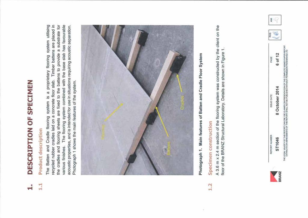
115 113
116 114
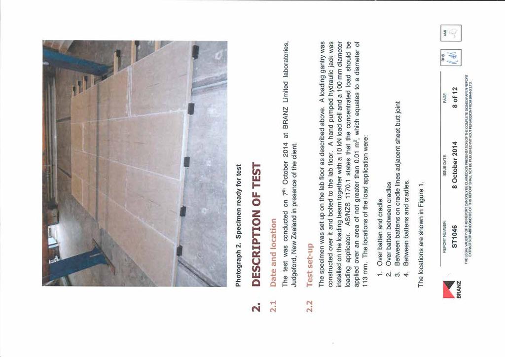
117 115
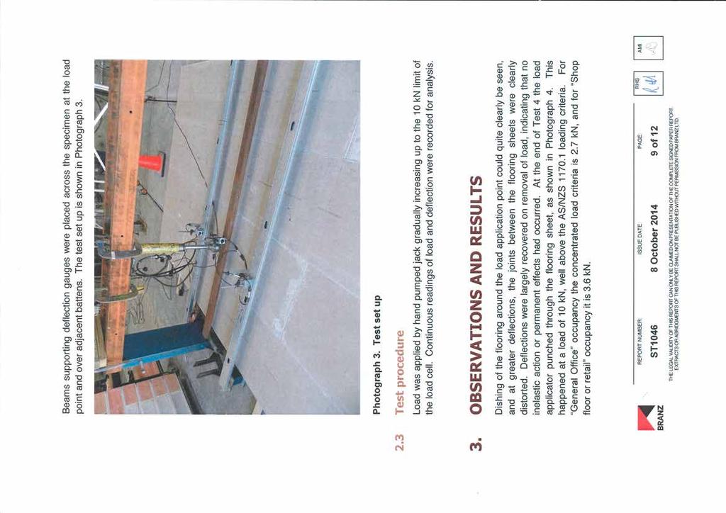
118 116
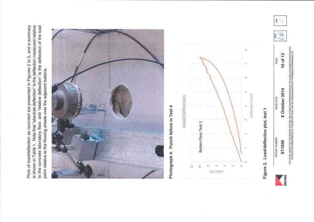
119 117
120 118
121 119
122 ADDITIONAL PRODUCTS 120
123 121

124 60mm 120mm ACM600C B&C SYSTEMS INTERNATIONAL Not to scale PATENT PENDING 122


125 ACM600C B&C SYSTEMS INTERNATIONAL PATENT PENDING 123

126 ACM275 Equipment Mounting Block Pat. Pending No ACM275 is an acoustic equipment mounting block, designed specifically for use on membrane surfaces. The ACM275 is installed on top of the membrane surface with approved dob of locating adhesive and doesn t require mechanical fixing. Typically used as a support device for electrical and plumbing services and most mechanical plant. The ACM275 provides sound and impact absorption, is easy to install and is non-invasive on both membrane and applied waterproofing products. Easy to install Protects Membrane Surfaces Sound & Impact Absorption For more information, please visit our website 124


127 ACM550 Equipment Mounting Block Pat. Pending No ACM550 is an acoustic equipment mounting block, designed specifically for use on membrane surfaces. The ACM550 is installed on top of the membrane surface with approved dob of locating adhesive and doesn t require mechanical fixing. Typically used as a support device for air conditioning units and most mechanical plant. The ACM550 provides sound and impact absorption, is easy to install and is non-invasive on both membrane and applied waterproofing products. Easy to install Protects Membrane Surfaces Sound & Impact Absorption For more information, please visit our website 125
Fire Resistant: Achieves FRL levels of 90/90/90 for load bearing walls.
 ( ) is a new and innovative system designed to provide high performance separating walls between units and apartments in low-rise residential and commercial projects. provides exceptional fire and acoustic
icore HR outperforms other building boards in many important ways including the following:
 icore HR is a new and innovative system designed to provide high performance separating walls between units and apartments in high-rise commercial projects. icore HR system provides exceptional fire and
Acoustic Cradle Levelling System
 Acoustic Cradle Levelling System CONCRETE FLOOR CRADLE & BATTEN Datasheet 52 01 18mm t&g chipboard @ 400mm centres 02 40mm min directly applied sand & cement or proprietary screed (min 80kg/m 2 ) 03 03
GIB Quiet Clip GIB CBI March Features and Benefits
 CBI - 5113 March 2002 GIB Quiet Clip Features and Benefits No special flooring systems required Easy fit Installation Significantly improves low frequency sound transmission Significantly improves low
SIKALASTIC-152 EXTERIOR WATERPROOFING MEMBRANE. Product. Scope. Appraisal No. 811 [2013] Appraisal No. 811 (2013) Amended 28 August 2017
![SIKALASTIC-152 EXTERIOR WATERPROOFING MEMBRANE. Product. Scope. Appraisal No. 811 [2013] Appraisal No. 811 (2013) Amended 28 August 2017](/thumbs/76/73001868.jpg "SIKALASTIC-152 EXTERIOR WATERPROOFING MEMBRANE. Product. Scope. Appraisal No. 811 [2013] Appraisal No. 811 (2013) Amended 28 August 2017") SIKALASTIC-152 EXTERIOR WATERPROOFING MEMBRANE Amended 28 August 2017 BRANZ Appraisals Technical Assessments of products for building and construction. Sika (NZ) Ltd PO Box 19 192 Avondale Auckland 1746
SIKALASTIC-152 EXTERIOR WATERPROOFING MEMBRANE Amended 28 August 2017 BRANZ Appraisals Technical Assessments of products for building and construction. Sika (NZ) Ltd PO Box 19 192 Avondale Auckland 1746
Specialists in Acoustic Flooring and House to Flat Conversions
 Sound Solution Consultants Ltd Po Box 755 Capel St Mary Ipswich Suffolk IP9 2WF Tel No: 0845 5212096 Fax No: 0845 5212097 Email: mpconsultservice@aol.com Specialists in Acoustic Flooring and House to Flat
Part E robustdetails. robustdetails. January 2017 Update Pack. Dear Colleague,
 Part E Pack Dear Colleague, This is the first 2017 update to the Part E Robust Details Handbook. In this update pack, we have focussed on clarifying the situation on incorporating underfloor heating (UFH)
SOUND INSULATION TESTING IN DWELLINGS
 SOUND INSULATION TESTING IN DWELLINGS Chris Dilworth, AWN Consulting This Presentation Discusses the standards by which we judge sound insulation performance. Presents the results of sound insulation tests
SoundPro CDM-ISO-LAT. Acoustic solution for floating isolated floors
 Jun 21 WILHAMS INSULATION FAR EAST SDN BHD SoundPro Acoustic solution for floating isolated floors Battens are designed to optimise sound insulation and impact isolation of floor constructions. They are
Edition October May (always refer to the latest manual as set out on
 LOXO PANEL INTER AND BLOCK TENANCY SYSTEMS WALLS TECHNICAL FIRE AND ACOUSTIC MANUAL REPORT PRODUCT DESCRIPTION AND BUILDING SYSTEM DETAILS Edition October May 2015 2014 (always refer to the latest manual
SECTION D Masonry Wall Systems. Contents. Introduction. Design Considerations. Installation. Components. System Specifications.
 SECTION D Wall Systems. Contents. SUBJECT Introduction Design Considerations Installation Components PAGE D2 D2 D4 D5 System Specifications Stud One Side Stud Both Sides Stud and Furring Channel Resilient
This page was. intentionally. left blank
 CONSTRUCTION Measurement of Airborne Sound Insulation of 8 Wall Assemblies Measurement of Airborne and Impact Sound Insulation of 29 Floor Assemblies Nordic Engineered Wood Report No. A1-006070.10 July
GTEK TM SOUND GTEK TM IMPACT
 APRIL 2016 TECHNICAL BROCHURE GTEK TM SOUND GTEK TM IMPACT gtekplasterboard.com.au GTEK TM SOUND WHY GTEK TM? WITH OUR ALL-AUSTRALIAN GTEK RANGE OF INTERIOR LINING PRODUCTS, YOU BENEFIT FROM SUSTAINABLE,
SINTEF Building and Infrastructure confirms that. Separating floors with Hunton Silencio 36 / Hunton Silencio Thermo
 SINTEF Certification No. 2330 Issued t: 18.02.2002 Revised: 17.06.2013 Valid until: 01.07.2018 Page: 1 of 5 SINTEF Building and Infrastructure confirms that Separating floors with Hunton Silencio 36 /
ARCHITECTURAL AND STRUCTURAL NOISE CONTROL SOLUTIONS
 13080/KIN BuyLine 1062 Providing solutions to common noise and vibration problems since 1958. ARCHITECTURAL AND STRUCTURAL NOISE CONTROL SOLUTIONS IIC 51 STC 72 FLOOR/CEILING STC 84 IIC 70 FLOOR/CEILING
HYDRATHANE INTERIOR WATERPROOFING MEMBRANE. Product. Scope. Building Regulations. Appraisal No. 959 [2017] Appraisal No. 959 (2017) BRANZ Appraisals
![HYDRATHANE INTERIOR WATERPROOFING MEMBRANE. Product. Scope. Building Regulations. Appraisal No. 959 [2017] Appraisal No. 959 (2017) BRANZ Appraisals](/thumbs/76/74150900.jpg "HYDRATHANE INTERIOR WATERPROOFING MEMBRANE. Product. Scope. Building Regulations. Appraisal No. 959 [2017] Appraisal No. 959 (2017) BRANZ Appraisals") Appraisal No. 959 [2017] HYDRATHANE INTERIOR WATERPROOFING MEMBRANE BRANZ Appraisals Technical Assessments of products for building and construction. Construction Chemicals Pty Ltd 49-57 Davis Street Wingfield
Appraisal No. 959 [2017] HYDRATHANE INTERIOR WATERPROOFING MEMBRANE BRANZ Appraisals Technical Assessments of products for building and construction. Construction Chemicals Pty Ltd 49-57 Davis Street Wingfield
Acoustic Testing of CLT and Glulam Floor Assemblies Nordic Engineered Wood Report No. A August 2016 CONSTRUCTION
 CONSTRUCTION Acoustic Testing of CLT and Glulam Floor Assemblies Nordic Engineered Wood Report No. A1-008253.1 19 August 2016 The results in this report only apply to the specimen that was tested Page
Loadbearing timber joist floors
 C06 Floors and ceilings Internal and separating floor systems Timber joists are widely used within internal floor and separating floor construction, both in residential and coercial applications. Our range
Staggered stud acoustic partition system
 C0 Partitions Staggered stud acoustic partition system All our systems are covered by SpecSure when using genuine Gyproc and Isover products is a non-loadbearing stud partition incorporating a single framework
SOUND SOLUTIONS TO MEET THE APPROVED DOCUMENT E (2003 EDITION) August 2008
 August 2008") SOUND SOLUTIONS TO MEET THE APPROVED DOCUMENT E (2003 EDITION) August 2008 PART E AT A GLANCE The New Approved Document E, (2003 Edition) was implemented on 1st July 2003. This applies to houses, flats,
SOUND SOLUTIONS TO MEET THE APPROVED DOCUMENT E (2003 EDITION) August 2008 PART E AT A GLANCE The New Approved Document E, (2003 Edition) was implemented on 1st July 2003. This applies to houses, flats,
EXCEL Medical Waste - Equipment Installation Section SECTION GYPSUM BOARD
 SECTION 09 29 00 GYPSUM BOARD PART 1 - GENERAL 1.1 DESCRIPTION This section specifies installation and finishing of gypsum board. 1.2 RELATED WORK A. Installation of steel framing members for walls, partitions,
TILING SPECIFICATIONS
 TILING SPECIFICATIONS SPECIFICATION NUMBER: NR204-16 PREPARED BY: Mike Cubley PREPARED FOR: Porcelain Plus ATTENTION: Kirk Pollock INSTALLATION: 712 Turner Floor and Wall Tiling Specification. M40 STONE/
Garage Conversion - Between and Under Joist Applications
 Issue 1, August 2013 CI/SfB (2 -) Rn7 (M2) Garage Conversion - Between and Under Joist Applications Flat Roof Insulation Introduction Celotex is the brand leading manufacturer of PIR insulation boards,
URSA MINERAL WOOL URSA Acoustic Roll
 - 073_Layout 1 02/10/2017 10:19 Page 1 URSA UK LTD Crest House 102-104 Church Road Teddington, Middlesex TW11 8PY United Kingdom Tel : 020 8977 96 97 Fax : 020 8977 94 56 Web : www.ursa-uk.co.uk E-mail
HACKER SOUND MAT II, to create a quieter living environment while meeting demanding project specifications in multi-family construction.
 HACKER SOUND MAT II HACKER SOUND MAT II, to create a quieter living environment while meeting demanding project specifications in multi-family construction. HACKER SOUND MAT II, a recycled rubber sound
Section Sound Control
 Ministry of Municipal Affairs PROPOSED CHANGE TO THE 2012 BUILDING CODE O. REG. 332/12 AS AMENDED CHANGE NUMBER: SOURCE: B-09-11-01 Ontario-NBC CODE REFERENCE: Division B / 9.11. DESCRIPTION OF THE PROPOSED
KINETICS NOISE CONTROL TEST REPORT #AT001035
 KINETICS NOISE CONTROL TEST REPORT #AT001035 KINETICS NOISE CONTROL PRODUCTS: o RIM I-2-16 ACOUSTICAL RATINGS: o STC 66 o IIC 63 TESTING AGENCY & REPORT NUMBER: o NRC-CANADA o B-3140.1 KINETICS DRAWING
Floor Insulation Underlayment Section Sound Control Matting
 Floor Insulation Underlayment Section 09618 Sound Control Matting Part I General 1.1 Summary A. Section includes a sound control material for achieving an STC and IIC rating in excess of 50 to meet building
AQUABLOK INTERIOR WATERPROOFING MEMBRANES. Product. Scope. Appraisal No. 724 [2017]
![AQUABLOK INTERIOR WATERPROOFING MEMBRANES. Product. Scope. Appraisal No. 724 [2017]](/thumbs/76/73615896.jpg "AQUABLOK INTERIOR WATERPROOFING MEMBRANES. Product. Scope. Appraisal No. 724 [2017]") WATERPROOFING MEMBRANES This Appraisal replaces BRANZ Appraisal No. 724 (2011) BRANZ Appraisals Technical Assessments of products for building and construction. Sika (NZ) Ltd PO Box 19 192 Avondale Auckland
WATERPROOFING MEMBRANES This Appraisal replaces BRANZ Appraisal No. 724 (2011) BRANZ Appraisals Technical Assessments of products for building and construction. Sika (NZ) Ltd PO Box 19 192 Avondale Auckland
NATIONAL GYPSUM COMPANY Wood Frame Walls And Ceilings Single- And Double-Layer Construction
 Walls And Ceilings Single- And Double-Layer Construction 09 9 00/NGC Single-Layer Construction The single-layer construction system consists of a single layer of Gold Bond brand Gypsum Board applied to
FIRE PROTECTION. GTEC Shaftwall systems 244 GTEC Shaftwall Stairwell systems 248 GTEC Horizontal Shaftwall systems 249 GTEC Encasement systems 250
 FIRE PROTECTION GTEC Shaftwall range uses a specially designed system to protect voids and shafts in buildings. It resists pressure changes and enables installation from one side of the shaft only. GTEC
The GlasRoc Shaftliner Type X advantage...
 C e r t a i n T e e d SHAFTLINER F o r A r e a S e p a r a t i o n F i r e w a l l s Shaftliner S Type X for Area Separation GlasRoc Shaftliner is a specially formulated product for applications where
ENKASONIC FLOOR UNDERLAYMENT 9110
 ENKASONIC FLOOR UNDERLAYMENT 9110 GS1197 Section 13080 SECTION 09618 SOUND CONTROL MATTING Part I General 1.1 Summary A. Section includes a sound control material for achieving an STC and IIC rating in
RMF Intercell. NBS Specification 2013 K41
 RMF Intercell NBS Specification 2013 K41 InterfaceFLOR BV. K41 Specification 40mm, 60mm, 80mm, 90mm and 110mm K41 Raised access floors To be read with Preliminaries/ General conditions. TYPES OF RAISED
June Residential Refurbishment Exposed soffit floors
 June 2010 Residential Refurbishment 3.4.2 Exposed soffit floors Residential refurbishment 3.0 Residential Refurbishment Exposed Soffit Floor Contents Introduction find online page Solution optimiser and
June Residential Refurbishment Separating walls
 June 2010 Residential Refurbishment 3.6.1 Separating walls Residential refurbishment 3.0 Residential Refurbishment Separating Walls Contents Introduction find online page Solution optimiser and pathfinder
CONTRACT NUMBER: W912DQ-08-C % CORRECTED DESIGN 28 JULY 2008
 SECTION 092900 - GYPSUM BOARD 1.1 SUMMARY A. This Section includes the following: 1. Interior gypsum board. 2. Tile backing panels. B. Related Sections include the following: 1. Division 06 Section "Rough
PLATON RUGGED, DIMPLED HIGH-DENSITY POLYETHYLENE (HDPE) MEMBRANE THAT KEEPS FOUNDATIONS AND FLOORING DRY ADVANCED TECHNOLOGY EASY INSTALLATION
 MEMBRANE THAT KEEPS FOUNDATIONS AND FLOORING DRY ADVANCED TECHNOLOGY EASY INSTALLATION") DRAINAGE SOLUTIONS SINCE 1908 PLATON RUGGED, DIMPLED HIGH-DENSITY POLYETHYLENE (HDPE) MEMBRANE THAT KEEPS FOUNDATIONS AND FLOORING DRY ADVANCED TECHNOLOGY EASY INSTALLATION PROVEN PERFORMANCE ARMTEC.COM
DRAINAGE SOLUTIONS SINCE 1908 PLATON RUGGED, DIMPLED HIGH-DENSITY POLYETHYLENE (HDPE) MEMBRANE THAT KEEPS FOUNDATIONS AND FLOORING DRY ADVANCED TECHNOLOGY EASY INSTALLATION PROVEN PERFORMANCE ARMTEC.COM
SECTION GYPSUM BOARD ASSEMBLIES
 SECTION 09 21 16 GYPSUM BOARD ASSEMBLIES PART 1 GENERAL 1.1 SECTION INCLUDES A. Metal stud wall and ceiling framing, 20 gauge. B. Metal channel suspended ceiling framing. C. Gypsum board. D. Gypsum sheathing.
TECHNICAL DATA SHEET AUS-FLEX MULTI
 FLEXIBLE TILE & STONE ADHESIVE POLYMER & RUBBER REINFORCED INTERNAL & EXTERNAL USE SUITABLE FOR: PORCELAIN TILE ALL MASONRY SURFACES CERAMIC TILE CONCRETE QUARRY TILE RENDER, BRICK & BLOCK WORK MOSAIC
COOK COUNTY ILLINOIS CONTRACT FOR WORK DOCUMENT NO Countywide Warehouse and Records Storage Center Hawthorne Project TKB No.
 SECTION 092900 GYPSUM BOARD PART 1 - GENERAL 1.1 RELATED DOCUMENTS A. Drawings and general provisions of the Contract, including General and Supplementary Conditions and Division 01 Specification Sections,
HOW TO: BOARD ROOMS WITH HIGH HUMIDITY AND CONDENSATION GTEC MOISTURE AND VAPOUR BOARD WITH PLASTERBOARD
 HOW TO: BOARD ROOMS WITH HIGH HUMIDITY AND CONDENSATION WITH PLASTERBOARD GTEC MOISTURE AND VAPOUR BOARD 3 MOISTURE AND HUMIDITY Kitchens, utility rooms and cloak rooms are areas of high humidity, modern
composition. Environmental Choice) as having lower environmental impact. Certification and further information is available at
 as having lower environmental impact. Certification and further information is available at") Application (Building Insulation Blanket), is a light weight flexible glass wool insulation product designed to: Thermally insulate commercial and industrial building Fit easily into standard framework,
Application (Building Insulation Blanket), is a light weight flexible glass wool insulation product designed to: Thermally insulate commercial and industrial building Fit easily into standard framework,
Xtratherm Thin-R Thermal Liner (XT/TL Grade)
") CERTIFICATE NO. 03/0183 DETAIL SHEET 4 Xtratherm Thin-R Thermal Liner (XT/TL Grade) PRODUCT DESCRIPTION: This Detail Sheet relates to Xtratherm Thin-R Thermal Liner, as defined in NSAI Agrément Certificate
CERTIFICATE NO. 03/0183 DETAIL SHEET 4 Xtratherm Thin-R Thermal Liner (XT/TL Grade) PRODUCT DESCRIPTION: This Detail Sheet relates to Xtratherm Thin-R Thermal Liner, as defined in NSAI Agrément Certificate
SECTION GYPSUM BOARD
 SECTION 09250 GYPSUM BOARD PART 1GENERAL 1.1 SUMMARY A. Related Documents: General and Supplementary Conditions of the Contract, Division 1 - General Requirements, and Drawings are collectively applicable
KINETICS NOISE CONTROL TEST REPORT #AT001067
 KINETICS NOISE CONTROL TEST REPORT #AT001067 KINETICS NOISE CONTROL PRODUCTS: o FLM- NEOPRENE PAD ACOUSTICAL RATINGS: o STC 69 o IIC 61 TESTING AGENCY & REPORT NUMBER: o NATIONAL RESEARCH COUNCIL OF CANADA
RSIC-1 ACOUSTIC ASSEMBLY
 RSIC-1 ACOUSTIC ASSEMBLY FLOOR/CEILING ASSEMBLY DIRECT FIX TO CONCRETE SLAB FCS3 DSWA FIIC 69 PAC INTERNATIONAL Inc. Toll Free 866-774-2100 Telephone 503-649-7700 CONSTRUCTION * Ceramic Tile * 1/4" James
Building Regulations
 Product 1.1 Technobond is a range of polyester fibre insulation used as thermal and acoustic insulating material in ceilings, roofs and walls of buildings. Appraisal No.69 [010] BRANZ Appraisals Technical
138 H-STUD AREA SEPARATION WALL SYSTEM
 H-STUD AREA SEPARATION WALL SYSTEM The fire-protection of gypsum-based Area Separation Walls is demonstrated in dramatic fashion by the results of this actual townhouse fire in which the two-hour fire-rated
A. ASTM C190 - Test Method for Tensile Strength of Hydraulic Cement Mortars
 SECTION 04850 (04 40 00) MSI PRECAST STONE VENEER SYSTEM PART 1 GENERAL 1.1 SECTION INCLUDES A. MSI Precast Stone Veneer for exterior and interior vertical surfaces. 1.2 RELATED SECTIONS Specifier Notes:
H R0 ACOUSTICAL PERFORMANCE TEST REPORT ASTM E 90 AND ASTM E 492. Rendered to AMORIM CORK COMPOSITES
 ACOUSTICAL PERFORMANCE TEST REPORT ASTM E 90 AND ASTM E 492 Rendered to AMORIM CORK COMPOSITES Series/Model: AcoustiCORK ECOx2 Sound Reduction Underlayment for LVT Plank Flooring Specimen Type: 152 mm
June Non - Residential Refurbishment Internal lining walls
 June 2010 Non - Residential Refurbishment 5.3.4 Internal lining walls Non-residential refurbishment 5.0 Non-residential Refurbishment Internal Lining Walls Contents Introduction find online page Solution
Tiling Tiling Finishes C08
 C08 Finishes In rooms subject to high or intermittent moisture conditions, the range of boards available for tiling offers flexibility of design and peace of mind when installed in both wall linings, lightweight
Chevy Chase Club June 30, 2008 Bowie Gridley Architects SECTION GYPSUM BOARD SHAFT WALL ASSEMBLIES
 SECTION 092116.23 - GYPSUM BOARD SHAFT WALL ASSEMBLIES PART 1 - GENERAL 1.1 RELATED DOCUMENTS A. Drawings and general provisions of the Contract, including General and Supplementary Conditions and Division
Standard specification for the application of Danosa Two-Layer waterproof roofing membrane to plywood & concrete surfaces.
 Standard specification for the application of Danosa Two-Layer waterproof roofing membrane to plywood & concrete surfaces. BRANZ Appraised No. 678 Ref: P3200 Rev 1 February 2016 Page 1 of 5 1.0 PREAMBLE:
EasylationWall. External Wall Insulation System. bringing european innovation
 EasylationWall External Wall Insulation System bringing european innovation EasylationWall... the new External Wall Insulation System using brick slips for stunning façades. EXTERNAL WALL INSULATION (EWI)
Floors Walls Roofs. Jabfloor Premium board Jablite Premium board Jabfloor board Jablite board. APPLICATION: Basements PRODUCTS: Vencel Resil Limited
 Floors Walls Roofs APPLICATION: Basements PRODUCTS: Jabfloor Premium board Jablite Premium board Jabfloor board Jablite board Vencel Resil Limited Head Office: Infinity House, Anderson Way, Belvedere,
DURABASE CI 1/5. Underlay mats for decoupling and waterproofing tiled flooring APPLICATIONS AND FUNCTION.
 Since the usage and finishing of the product is not under our control, we accept no liability for the success of the work and can therefore only guarantee the nature of our products as per the accompanying
The flooring comes complete with a 20 year structural warranty providing peace of mind, which most of our competitors cannot offer.
 Gymflex solid hardwood flooring is a premium quality pre-finished timber floor suitable for both domestic and commercial applications. The floor is available in a Maple 2 strip board, with the added option
Important Notice. QuietRock by PABCO Gypsum Cherry Street Newark, CA
 Important Notice In August 1, 2013, PABCO Gypsum, a division of PABCO building products, LLC acquired the QuietRock business and operations from Serious Energy, Inc. Serious Energy, Inc. corporate structure
Sandwich panel SPA Product description
 Sandwich panel SPA Product description Ruukki offers a sandwich panel system that combines an attractive appearance with excellent thermal insulation and fire-resistance. The panels are of a lightweight,
4411N 4411G 4412N 4412G
 Extreme Sealing Tape Technical Data October, 2011 Product Description 3M Extreme Sealing Tape is a family of single coated, pressure sensitive adhesive tapes designed for difficult sealing applications.
Important Notice. QuietRock by PABCO Gypsum Cherry Street Newark, CA
 Important Notice In August 1, 2013, PABCO Gypsum, a division of PABCO building products, LLC acquired the QuietRock business and operations from Serious Energy, Inc. Serious Energy, Inc. corporate structure
Firestone Polyiso Boards
 Firestone Polyiso Boards Superior energy efficiency. Superior protection. Firestone Polyiso Boards POLISOBROUK10.indd 1 1/04/10 14:26 Firestone Polyiso Boards Firestone total roofing systems Since Firestone
ROCKMAX MAG CEMENT BOARD
 2017 Fire proof Water proof Mould proof ROCKMAX MAG CEMENT BOARD NexGen Magnesium Product 20 Premium fireproofing wall panel with independent warranty number Durable Strong Light www.rockmaxpan.com KUNSHAN
Acoustic Design Criteria
 Apartment Acoustics Apartment Buildings Acoustic Design Criteria Building Code of Australia: - Intertenancy walls and floors - Corridor walls and doors - Floor impact isolation - Lift, stair and core walls
I-STUD Shaftwall System
 I-STUD Shaftwall System Summit Tower I-Stud and CertainTeed Shaftliner TM MILL CERTIFIED Steel-Con 00% GALVANIZED Steel Construction Systems UL Evaluation Report No. ER3660-02 Intertek The I-Stud is approved
Product Data Sheet SikaFuko Swell-1 Positioning Description Uses Advantages Approval / Standards Construction Product Data Packaging
 Product Data Sheet Version Nos.: 0414 SikaFuko Swell-1 Hydrophilic, swellable hose for sealing construction joints in watertight structures Construction Positioning Description Uses Swellable and injectable
System Recommendation SR0618
 Ardex Australia Pty Ltd ABN 82 000 550 005 Unit 7, 20 Powers Road, Seven Hills NSW 2147 Australia Telephone + 61 2 9851 9100 Facsimile +61 2 9838 7970 www.ardexaustralia.com System Recommendation SR0618
BISON PRECAST FLOORING SPECIFICATION
 BISON PRECAST FLOORING SPECIFICATION 1.0 SCOPE OF THE SPECIFICATION 1.01 Relates to: This specification covers the design, manufacture and associated site work of the following types of floors:- Hollowcore
DIVISION 13 - SPECIAL CONSTRUCTION SECTION ACOUSTICAL PANEL ENCLOSURE
 DIVISION 13 - SPECIAL CONSTRUCTION SECTION 13080 - ACOUSTICAL PANEL ENCLOSURE 1 GENERAL 1.01 SUMMARY A. ACOUSTIC ENCLOSURE CONSISTING OF WALLS, CEILING, STRUCTURAL FRAMING, CONNECTING MEMBERS, DOORS, WINDOWS,
Outline NBS Specification. Protec System to PVC Single Ply (Waterproofing Only)
") Outline NBS Specification Protec System to PVC Single Ply (Waterproofing Only) This document is a guide to assist in the production of tender documents only and is not project specific. A site survey is
Outline NBS Specification Protec System to PVC Single Ply (Waterproofing Only) This document is a guide to assist in the production of tender documents only and is not project specific. A site survey is
FOR: CEMCO - California Expanded Metal Products Co. Sound Transmission Loss Test
 FOR: CEMCO - California Expanded Metal Products Co. Sound Transmission Loss Test Industry, CA ON: Bare 1 Inch Thick USG LEVELROCK Brand CSD Floor Underlayment on USG LEVELROCK SRM-25 Sound Mat on CEMCO
Roof. Installation Instructions PINK BATTS CEILING INSULATION. Safety: pinkbatts.co.nz INSTALLATION INSTRUCTIONS
 Roof PINK BATTS CEILING INSULATION Installation Instructions Correct installation with no compression, gaps or folds is critical to ensure Pink Batts ceiling insulation performance is not compromised.
INSTALLATION INSTRUCTIONS FOR WICANDERS HYDROCORK
 INSTALLATION INSTRUCTIONS FOR WICANDERS HYDROCORK GENERAL INFORMATION Hydrocork floors are intended for indoor use only. Please read the following instructions before installation. Hydrocork connection
Corium Brick Rainscreen System Specifications
 CORIUM BRICK RAINSCREEN SYSTEM PART 1 - GENERAL 1.1 SUMMARY A. Work Included: The Work of this Section shall include but not be limited to the following: 1. Corium brick plates 2. Galvanized and coated
DIVISION 9 - SECTION QTscu Re-bonded Recycled Rubber Impact Sound Insulation Patent No. RE 41,945
 Revised on 11/17/11. Supercedes all previous versions. Check website for updates. DIVISION 9 - SECTION 09 60 00.11 QTscu Re-bonded Recycled Rubber Impact Sound Insulation Patent No. RE 41,945 PART 1.0-
RSIC-1. RSIC-1, the Low Cost, High Performance, Noise control Solution. RSIC-1 specifications:
 RSIC-1 The RSIC-1 is designed for use with any wood framed, steel framed, CMU, or concrete wall and ceiling system where noise control is needed. The RSIC-1 assembly decouples and isolates the gypsum board
The World of Floor Technology
 The World of Floor Technology THE POSI-JOIST TECHNICAL HANDBOOK FEATURING An Introduction to Posi-Joist Installation Guidance Posi-Joist Applications throughout your building Acoustic Performance & Separating
GypLyner UNIVERSAL Metal framed wall lining system
 Metal framed wall lining system Pizza Express, York 30 Metal framed wall lining system wall lining system is a cost-effective, virtually independent metal frame drylining. It is a general purpose system
HOW TO: INSULATE YOUR HOME AND UNDERSTAND U-VALUES GTEC THERMAL BOARD WITH PLASTERBOARD
 HOW TO: INSULATE YOUR HOME AND UNDERSTAND U-VALUES WITH PLASTERBOARD GTEC THERMAL BOARD 1 BUILDING INSULATION THE REGULATIONS Building regulations are in place to drive improvements in thermal efficiency,
1.3 Work shall include all reinforcement and accessories necessary to complete installation.
 CERAMIC TILING GENERAL INFORMATION 1.1 Ceramic mosaic tile floors and bases, glazed wall tile wainscots and walls, and marble thresholds. 1.2 Installation will typically be with latex-portland cement mortar
TILE TILE
 09300 - TILE 09300-1 PART ONE: GENERAL 1.1 Description TILE 1.1.1 Work of this Section, as shown or specified, shall be provided by the Interior Contractor and shall be in accordance with the requirements
ACOUSTIC INSULATION UNDER SCREED made from recycled rubber granules
 ACOUSTIC INSULATION UNDER SCREED made from recycled rubber granules SOLUTIONS FOR CONSTANT LOADS UP TO 20 t/m² MADE IN GERMANY Engineered solutions against noise. DAMTEC Project DC Tower Vienna, Austria
Wall. . Made from over 80% recycled glass making sustainable use of waste
 Application Pink Batts wall insulation is a lightweight flexible glass wool insulation product designed to: Thermally insulate timber and steel framed walls Fit easily into standard wall constructions,
Presented By: Jim O Neill. Acoustics
 Presented By: Jim O Neill Acoustics Topics STC and IIC 101 Sound in floors Sound in walls Noise In Multifamily Measurements of Noise Two ASTM Standards STC Sound Transmission Classification Measurement
DURABASE CI. Underlay mats for decoupling and sealing tiled flooring 1/5 A P P L I C A T I ONS AND FUNCTION.
 Since the usage and finishing of the product is not under our control, we accept no liability for the success of the work and can therefore only guarantee the nature of our products as per the accompanying
E R0 ACOUSTICAL PERFORMANCE TEST REPORT ASTM E90. Rendered to: PAC INTERNATIONAL, LLC
 ACOUSTICAL PERFORMANCE TEST REPORT ASTM E90 Rendered to: PAC INTERNATIONAL, LLC TYPE: Wall, Steel (0.018" / 25 ga), RSIC-V, STC 67 DATA FILE NO: E4748.01A STC 67 OITC 56 Test Specimen Identification: (Source
Fire Barrier Duct Wrap 615+
 Fire Barrier Duct Wrap 615+ Duct Wrap Fire Protection System for Commercial Kitchen Grease and Ventilation Air Ducts Product Data Batts and blankets for use in fire resistive duct assemblies see UL fire
HYBRID. Pre-Laying Checks
 Warning Veles CK has been developed for exceptional stability in low and high temperatures, however, after installation extreme temperatures (under 5 C or over 50 C) should be avoided by use of interior
Carpenter Level 2 Rev. September 2017
 Level 2 A5 Site Layout II Duration: 14 hours 7 hours 7 hours Upon completion of this unit the apprentice will demonstrate knowledge of site layout tools and equipment and their applications and procedures
for the master tradesman Setcrete Product Guide
 Professional Flooring products for the master tradesman Setcrete Product Guide Professional flooring products for the master tradesman Floor Levelling Compounds SETCRETE Floor Levelling Product Selector
Structural Performance Tests of VHB Structural Glazing Tapes
 3 Performance Tests of VHB Glazing Tapes Technical Bulletin September, 2010 Introduction 3M VHB Acrylic Foam Bonding Tapes have been used worldwide in a variety of applications in the construction industry.
Reinventing construction
 Reinventing construction Silence, comfort and durability 2018 EDITION Construction Cork, an exceptional raw material Cork is the outer bark of the cork oak tree (Quercus Suber L.), the 100% natural plant
Design. Boral CinemaZone Fact Sheet. Windows. Acoustic sealants. Sound absorptive panels. Ventilation. Floor coverings. The vision.
 Windows Like doorways, windows can be a significant source of sound leakage. For maximum isolation, windows should either be removed or built over internally - leaving the house facade unaffected. If natural
SECTION RESILIENT SHEET FLOORING
 SECTION 09 65 16 RESILIENT SHEET FLOORING SPEC WRITER NOTE: Delete text between // // not applicable to project. Edit remaining text to suit project. PART 1 - GENERAL 1.1 SUMMARY A. Section Includes: 1.
Insulated Panels. Insulated Roof Systems. Kingspan X-dek. KS1000 XD Longspan Roofpanel. Systems. Insurer Approved
 Insulated Panels 02 2010 Insulated Roof Systems Kingspan X-dek KS1000 XD Longspan Roofpanel Insurer Approved Systems X dek TM Frame-to-Frame Long Spanning Insulated Roof Deck X dek TM is an insulated roof
SECTION SHEET MEMBRANE WATERPROOFING AND CRACK ISOLATION
 SECTION 093000 - SHEET MEMBRANE WATERPROOFING AND CRACK ISOLATION PART 1 - GENERAL This specification includes the sheet membrane used as waterproofing, vapor retarder, and crack isolation in conjunction
SECTION WOOD GYMNASIUM FLOORING
 HORNER SAFE 2 SYSTEM Page 1 of 3 SECTION 096466 --- WOOD GYMNASIUM FLOORING PART 1-GENERAL 1.1 DESCRIPTION A. This document specifies a wood strip athletic floor system consisting, in general, of wood
Regupol CONSTRUCTION. Regupol BA. Heavy duty screed isolation. Regupol BA. Excellent impact performance.
 CONSTRUCTION Regupol Heavy duty screed isolation Excellent impact performance www.berleburger.de CONSTRUCTION The properties heavy duty screed isolation Offers long term performance, with minimal creep,