Special track. Jarosław Zwolski, PhD CE. 1. Slab track. 2. Track on bridges
|
|
|
- Shawn Rich
- 6 years ago
- Views:
Transcription


1 Special track 1. Slab track 2. Track on bridges Jarosław Zwolski, PhD CE
. 3. Increase of transversal stiffness ot the track.")
2 Genesis 1. Requirement of plastic deformation elimination in track. 2. Elimination of the ballast layer as the most flexible element of the classical pavement (and delimitation of the maintenance costs). 3. Increase of transversal stiffness ot the track. Stages of the development: a) classical & block sleepers, b) longitudinal block sleepers, c) zigzac sleepers, d) concrete slabs of different dimensions, e) continuous monolithic concrete slab
.")
3 Subgrade Depth Pavement The idea 1. A multi-layer system with diverse elasticity moduli. 2. The lower layer the lower stiffness it has (the loads spread). 3. Methods of design are the same as in road engineering (CBR standard, ground elasticity module etc.). UIC60 rail Concrete carrying layer UIC60 rail Sleeper Concrete/asphaltic carrying layer Hydraulicallybonded layer Hydraulically-bonded layer Subbase Subbase Subgrade soil Subgrade soil
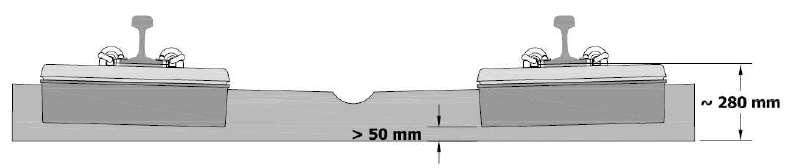
4 Application of the ballastless track: 1. On grade crossing 2. On stations (the track at the platforms) 3. In tunnels and bridges 4. Tramway trackr on the traways shared with road traffic 5. On lines (West Europe, Asia) REMARKS: 1. The loads from rails are transferred on the concrete slab and then on the reinforced and dewatered subgrade. 2. The rails can be supported point-wise (like in a classic track) or line-wise, using another fastening method. 3. Very often the fastening system provides also some vibration- and noisedamping elements. 4. The ballastless track is sensitive on uneven subgrade settlement (difficult diagnosis and retrofitting). 5. Doesn t need maintenence (tamping).

5 Advantages Good damping properties Low noise emission Fast building process Easy maintenance (doesn t need tamping of the ballast) Easy dewatering Low height of the pavement Low weight of the pavement High precision of the rails rectification Long life (ca. 30 years and more) No geometry deformation under normal conditions Disadvantages High price of the design, building and retrofitting (in case of..) Needs careful maintenance of the soft elements Complicated structure Short experiences of operation Sensitivity on uneven subgrade settlement


6 1. Ballastless pavement of tracks on the Central Station in Warsaw. 2. Elimination of loose materials down to the depth of 1.0 m (from the rail head).

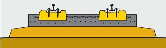
7 REMARKS: 1. The track on the Akabane Station has been developed by Railway Technical Research Institute of Japan. 2. Longitudinal post-tensioned concreste sleepers of length 6.25 m are kept in the gauge by thin-walled steel pipes. 3. The track is based on transversal concrete elements with some antivibration pads.

8 1. The Brandleite Tunnel. 2. GETRAC A3 system. The concrete sleepers are based on specially prepared asphalt layer. The horizontal forces are carried by concrete anchors.
 Chur, Switzerland and b) Drezno,")
9 a) b) 1. a) Chur, Switzerland and b) Drezno, Niemcy. 2. System Rheda City


10 Ballastless track of High Speed Line in China Ballastless track of RHEDA 2000 system for High Speed Line in Tajwanie.
11 Submerged in the structure With sleeppers With point support Laid on the structure Without sleepers Ballastless track With rails submerged in the structure With linear support With rails fastened to the structure The most important suppliers: GETRAC RHEDA 2000 EDILON ZÜBLIN SONNEVILLE MAX BÖGL HEITCAMP CDM Leonhard Weiss The technologies can involve casting in situ or using precast elements.


12 HBL - hydraulically-bonded layer a layer of soil mixed with water and cement for increase its strength and time stability Scheme of layers The finished track
")


13 RHEDA (Classic) RHEDA (Sengeberg) RHEDA-Berlin HST V1 RHEDA-Berlin HST V2 RHEDA-Berlin HST V3 RHEDA 2000


14 FPL frost protection layer usually made of compacted permeable soil The finished double track line Scheme of layers

15


16 Rheda City Rheda City Green

17 The sleepers distance equals to 75 cm

18
19 tramway lane axis tramway lane road lane 2 rubber fastening strips elastic mass block rail 7 cm rubber tape 1 cm precast concrete slab 18 cm asphaltic concrete 12 cm crushed stone 30 cm sand subbase 10 cm rubber fastening strips rubber tape elastic mass (polyurethane or bitumin-caoutchouc) precast concrete slab asphaltic concrete

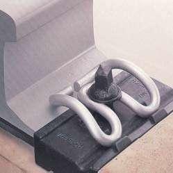
20 Precast or cast-in-situ concrete slab with two channels for rails or a deck structure shaped with steel channels. The rails are fastened in the channels by means of Edilon Corkelast mass based on polyurethane resin and it is linearly supported by the anti-vibration pad called Edilon Resilient Strip.
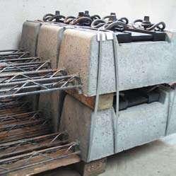
21 Embedded Block System with precast concrete box 1. coating of the supporting block - Edilon Corkelast mass, 2. precast concrete box, 3. concrete supporting block, 4. PE coating tube, 5. fastening steel pad, 6. sub-rail pad, 7. elastic clip, 8. screw, 9. rail, 10. anti-vibration pad Edilon Resilient Strip The rails are fastened by separate supporting blocks embedded in precast box (concrete, composite or steel) by means of the elastic mass Edilon Corkelast.


22 The prepared substructure 1. The soil compacted up to the module E 2 >45 MPa. 2. Layer of thickness 37 cm made of crushed stone with granularity 0/31,5 mm and compacted up to module E 2 >120 MPa. 3. Levelling course made of coarse grit or light concrete.


23
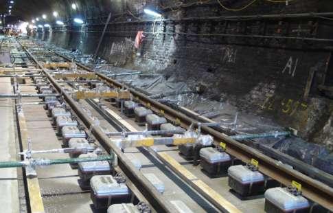

24 Track assembling in a tunnel The finished track
 5. dilatation slot 6. fastening elements 7.")
25 1. frost-protection layer 2. hydraulically bonded layer, d=30 cm 3. levelling course (mortar) 4. concrete slab, prestressed or reinforced by steel fibre (6.50 x 2.25 x 0.20 m) 5. dilatation slot 6. fastening elements 7. an opening for the mortar to flow out 8. connectors to the following slab


26 9. connectors for joining the following slab 10. dilatation space


27

28


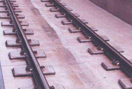
29 1. Building a classical ballasetd track but in a concrete trough laid on a HBL. 2. After assembling the track ladder and tamping the ballast it is filled with mortar.


30 1. Pouring of light concrete layer 4. Placing the reinforcement and concreting 2. Placement of the rails prepared with the lining on the temporary supports in rough geometry 5. Disassembling of the supports 3. Placement of steel supports, hanging up the rails, welding and rectification to the final geometry 6. Finishing with the road pavement


31
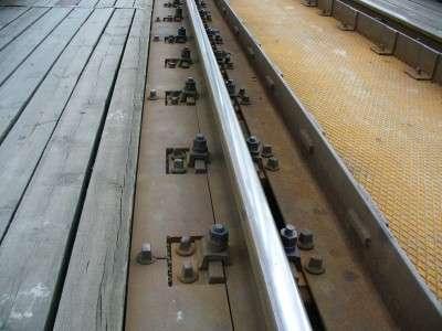
32 1. Methods of the track placing on the bridge A) Direct fastening of the rails to the structure
33 1. Methods of the track placing on the bridge B) Rails on sleepers supported on the main girders
34 1. Methods of the track placing on the bridge C) Rails on sleepers supported on the stringers (longitudinal deck elements)
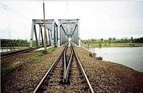
35 1. Methods of the track placing on the bridge D) Rails and sleepers with ballast layer on the dect shaped as a trough Minimum ballast thickness together with sleeper and the rail should be 70 cm due to dynamic performance and the space for ballast cleaning machines.

36 Tamping machine on the bridge.
 ballastless track Max")

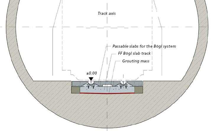
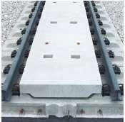
37 1. Methods of the track placing on the bridge E) ballastless track Max Bögl system is shown in the pictures but other systems are also applied.
38 2. The track in profile standard requirements Track on a bridge longer than 30 m should be rectified to the technological elevation introduced during the span construction (calculated taking into account the deflection caused by the dead load and a half of the movable loads). z f k 1 4 z- ordinate value measured from the level of the support for the abscissa x measured from the middle of the span f k - maximum z in the middle of the span l l - theoretical length of the span z x l l 2 z
39 3. The track in cross-section - requirements In case of the track in curve the cant is applied by means of rotation of sleepers and wooden pads to fit the pavement to the deck elements. This solution can be met in existing bridges.
 The track with sleepers should be fastened to the structure of a steel bridge of length L o =20-60 m in the way enabling longitudinal movement of one structure with regard to another.")
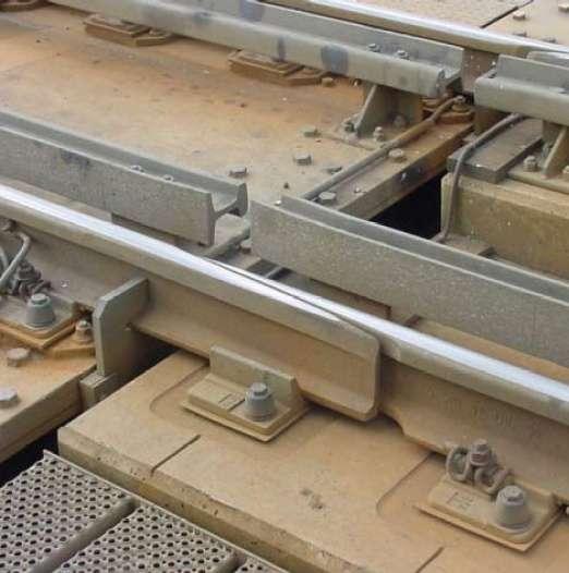
40 4. Requirements related to the thermal elongation a) Use of long rails they should be welded on the length of the bridge and the joints should be located at least 6 m from the ends. b) The track with sleepers should be fastened to the structure of a steel bridge of length L o =20-60 m in the way enabling longitudinal movement of one structure with regard to another. c) On the steel structures longer than 60 m, over the movable bearing the dilatation devices on the track should be installed. welding traffic direction stock rails extension joints bridge span L>60 m blades movable bearing movable bearing


41 Expansion joints on a bridge. Remark: On multitrack lines the expansion joints have to be placed in accordance to the normal traffic: trains should run in the direction from the blades to the stock rails.
42 5. Safety requirements For minimization of derailment effects on bridge along the running rails additional guiding rails should be placed (made of used rails, rolled shapes etc.) with the distance to the running rails in the range mm. This applies to the track: a) on bridges longer than 20 m, b) on bridges of the length in the range 6-20 m located: on curves with radius shorter than 350 m and on transition curves, in places where effects of derailment could be especially dangerous: on stations, on embankments higher than 4 m, under viaducts and close to control towers.
43 Derailment protection in Max Bögl system
RECENT DEVELOPMENTS IN SLAB TRACK APPLICATION
 Delft University of Technology, The Netherlands Faculty of Civil Engineering, Section of Roads & Railways Delft University of Technology RECENT DEVELOPMENTS IN SLAB TRACK APPLICATION Coenraad Esveld Professor
ScienceDirect. Analysis and design of steel bridges with ballastless track
 Available online at www.sciencedirect.com ScienceDirect Procedia Engineering 111 (2015 ) 702 708 XXIV R-S-P seminar, Theoretical Foundation of Civil Engineering (24RSP) (TFoCE 2015) Analysis and design
System DFF 21. Highly elastic rail fastening for conventional rail and metro the optimum single support point for slab track
 System DFF 21 Highly elastic rail fastening for conventional rail and metro the optimum single support point for slab track System DFF 21 Highly elastic rail fastening for conventional rail and metro the
The Ballastless Track Technology For China High Speed Line
 The Ballastless Track Technology For China High Speed Line Jijun Wang Senior Researcher, CARS May 4 th 2011 1 Contents 1. Application of Ballastless Track in China 2. Technical Features of Ballastless
Spectrum of Axles Approach
 Spectrum of Axles Approach Typical Axle Load Spectrum Axle Load (kn) Single Number of Axles Tandem Tridem Quad 50 60 5,000 400 100 5 61 80 3,000 2,000 500 10 81 100 200 5,000 800 30 101 120 50 4,000 1,000
The New Incremental Launching Construction Technology of Jiubao Bridge Long-span Hybrid Arch-girder Structure
 The New Incremental Launching Construction Technology of Jiubao Bridge Long-span Hybrid Arch-girder Structure C.Y. Shao Shanghai Municipal Engineering Design & Research General Institute (Group) Co. Ltd.,
Rail Structure Interaction
 Rail Structure Interaction Case Study Modelling and Benefits Jeremy Barnes Associate Director Hewson Consulting Engineers Nathan Griffiths Design Engineer Hewson Consulting Engineers Introduction Development
THE SLAB TRACK SOLUTION FOR THE REQUIREMENTS OF TOMORROW LOW VIBRATION TRACK (LVT)
") THE SLAB TRACK SOLUTION FOR THE REQUIREMENTS OF TOMORROW LOW VIBRATION TRACK (LVT) LOW VIBRATION TRACK (LVT) THE SLAB TRACK SOLUTION FOR THE REQUIREMENTS OF TOMORROW BLS Netz AG LVT, one of the first non-ballasted
THE SLAB TRACK SOLUTION FOR THE REQUIREMENTS OF TOMORROW LOW VIBRATION TRACK (LVT) LOW VIBRATION TRACK (LVT) THE SLAB TRACK SOLUTION FOR THE REQUIREMENTS OF TOMORROW BLS Netz AG LVT, one of the first non-ballasted
Design of Rigid Pavements
 Traffic and Highway Engineering (ІІ) CVL 4324 Chapter 20 Design of Rigid Pavements Dr. Sari Abusharar Assistant Professor Civil Engineering Department Faculty of Applied Engineering and Urban Planning
SLAB TRACK FOR THE NEXT 100 YEARS
 SLAB TRACK FOR THE NEXT 100 YEARS David N. Bilow, P.E., S.E. and Gene M. Randich, P.E. Portland Cement Association Skokie, IL ABSTRACT Various types of concrete slab track are in service in Japan, Europe
Application Study on Elastomer Expansion Joint in Heavy Haul Railway
 Journal of Civil Engineering and Architecture 9 (2015) 1047-1053 doi: 10.17265/1934-7359/2015.09.004 D DAVID PUBLISHING Application Study on Elastomer Expansion Joint in Heavy Haul Railway Leran Wang,
Slab Track Austria. System ÖBB-PORR elastically supported slab
 Slab Track Austria System ÖBB-PORR elastically supported slab 5. 2. 3. 4. 7. 6. Five holes for spindles 2. ÖBB-PORR slab 3. elastomeric layer 4. concrete joint sealing compound 5. rail support seat 6.
Design of Steel-Concrete Composite Bridges
 Design of Steel-Concrete Composite Bridges to Eurocodes Ioannis Vayas and Aristidis Iliopoulos CRC Press Taylor & Francis Croup Boca Raton London New York CRC Press is an imprint of the Taylor & Francis
A PRODUCT FROM KANTAFLEX (INDIA) PVT LIMITED
 PVT LIMITED") ELASTOMERIC BRIDGE BEARING TO LATEST IRC: 83-015 (PART - II) Kanta System of Elastomeric bridge bearing is made out of Poly chloroprene rubber having low crystallization rates and adequate shelf life,
ELASTOMERIC BRIDGE BEARING TO LATEST IRC: 83-015 (PART - II) Kanta System of Elastomeric bridge bearing is made out of Poly chloroprene rubber having low crystallization rates and adequate shelf life,
Hollow Core Slabs Applications
 NORDIMPIANTI P R O D U C T S APPLICATIONS T U R N K E Y S E R V I C E G L O B A L Hollow Core Slabs Applications Hollow Core Slabs Technology for the Precast and Prestressed Concrete Industry HOLLOW RESIDENTIAL,
RHEDA MRT The ballastless track for underground and surface commuter transit
 RHEDA MRT The ballastless track for underground and surface commuter transit 2 3 Cities on the move Living and working today confront people with increasing demands for mobility. Planners and engineers
SERIES 1100 KERBS, FOOTWAYS AND PAVED AREAS
 MANUAL OF CONTRACT DOCUMENTS FOR HIGHWAY WORKS VOLUME 1 THE SPECIFICATION FOR HIGHWAY WORKS SERIES 1100 KERBS, FOOTWAYS AND PAVED AREAS Contents Clause Title Page 1100 (02/17) General 2 #1101 Precast Concrete
DYNAMICS OF A PRECAST SYSTEM FOR HIGH-SPEED RAILWAY TRACKS
 COMPDYN 2011 3 rd ECCOMAS Thematic Conference on Computational Methods in Structural Dynamics and Earthquake Engineering M. Papadrakakis, M. Fragiadakis, V. Plevris (eds.) Corfu, Greece, 25 28 May 2011
Design and Construction of the SH58 Ramp A Flyover Bridge over IH70. Gregg A. Reese, PE, CE, Summit Engineering Group, Inc.
 Design and Construction of the SH58 Ramp A Flyover Bridge over IH70 Gregg A. Reese, PE, CE, Summit Engineering Group, Inc., Littleton, CO ABSTRACT: The SH58 Ramp A bridge in Golden, CO is the latest on
Structural - Engineering Review Checklist
 Structural - Engineering Review Checklist Project: List Corridor Criteria ID Review Priority (H,M,L) TOPICS S-_-## Structural Design Codes, Manuals and Specifications 6.1.0 REFERENCES DESIRED Criteria
Municipal Inspection and Construction Guidelines Section I Roadworks SECTION I ROADWORKS I-1 GENERAL
 I-1 GENERAL SECTION I ROADWORKS The Consultant Engineer is to monitor all specified asphalt, granular materials and sub-grade preparation to ensure all road and curb construction is undertaken as outlined
Alberta Bridge Inventory STANDARD BRIDGE & CULVERT COMPONENTS. Standard Bridges. Typical Bridge Components. In Alberta there are about 13,300 bridges.
 STANDARD BRIDGE & CULVERT COMPONENTS Alberta Bridge Inventory In Alberta there are about 13,300 bridges. Types of bridges in Alberta: Standard bridges 3521 (26%) Bridge size culverts 8348 (63%) Major bridges
Trackbed Evaluation and Design Using FWD Deflections as Performance Indicators
 Trackbed Evaluation and Design Using FWD Deflections as Performance Indicators 7th European FWD Users Group 9 th International Conference on Bearing Capacity of Roads, Railways and Airfields Trondheim,
DIVISION 3 PAVEMENT (FLEXIBLE AND RIGID) CONSTRUCTION SPECIFICATIONS
 CONSTRUCTION SPECIFICATIONS") OPS GENERAL CONDITIONS OF CONTRACT NOV 2006 General Conditions of Contract DIVISION 1 GENERAL S OCT 92 102 Weighing of Materials NOV 2004 106 Electrical Work NOV 2003 120 The Use of Explosives APR 2006
OPS GENERAL CONDITIONS OF CONTRACT NOV 2006 General Conditions of Contract DIVISION 1 GENERAL S OCT 92 102 Weighing of Materials NOV 2004 106 Electrical Work NOV 2003 120 The Use of Explosives APR 2006
Progressive Erection Applied to Box Girder with Strutted Wing Slab
 Progressive Erection Applied to Box Girder with Strutted Wing Slab Koji Osada 1, Taketo Kanamoto 1, Kimito Saito 2, Takahiro Arai 2 1 Introduction The Uchimaki Viaduct is a multi-span continuous box girder
Service life extension of existing precast concrete girders
 Concrete Repair, Rehabilitation and Retrofitting II Alexander et al (eds) 29 Taylor & Francis Group, London, ISBN 978--415-4685-3 Service life extension of existing precast concrete girders D.I. Banic,
ROAD PAVEMENTS GENERAL
 ROAD PAVEMENTS GENERAL Contents Clause Title Page 701 Pavement Construction... 2 702 Horizontal Alignments, Surface Levels and Surface Regularity of Pavement Courses... 2 703 Not Used... 4 704 Not Used...
Rail Track Analysis Wizard
 Rail Track Analysis Wizard M I D A S I T 111-1 01 Rail Track Analysis Wizard The Rail Track Analysis Wizard builds a model that is used for checking the additional stresses and the displacements due to
RETROFITTING AN EXISTING BALLAST DECK RAIL BRIDGE WITH A BALLASTLESS DECK IN AN OPERATIONAL COAL RAIL ENVIRONMENT
 RETROFITTING AN EXISTING BALLAST DECK RAIL BRIDGE WITH A BALLASTLESS DECK IN AN OPERATIONAL COAL RAIL ENVIRONMENT Evan Lo Andres Moreno Lara Simon Larsen Bachelor of Engineering Master of Engineering Bachelor
MIDAS Training Series
 MIDAS midas Civil Title: All-In-One Super and Sub Structure Design NAME Edgar De Los Santos / MIDAS IT United States 2016 Substructure Session 1: 3D substructure analysis and design midas Civil Session
Behavior of a multiple spans cable-stayed bridge
 Tailor Made Concrete Structures Walraven & Stoelhorst (eds) 2008 Taylor & Francis Group, London, ISBN 978-0-415-47535-8 Behavior of a multiple spans cable-stayed bridge S. Arnaud, N. Matsunaga, S. Nagano
Highway construction C 5
 Highway construction C 5 Contents Equipments used in Highway Construction Construction of Earth Roads Gravel Roads Water Bound Macadam Roads Bituminous Pavements Cement Concrete Pavements Equipment used
Construction Specification for Utility Adjustments
 Engineering & Construction Services Division Standard Specifications for Road Works TS 4.50 September 2017 for Utility Adjustments Table of Contents TS 4.50.01 SCOPE... 2 TS 4.50.02 REFERENCES... 2 TS
APPENDIX B ABC STRUCTURES DESIGN GUIDE
 APPENDIX B ABC STRUCTURES DESIGN GUIDE The Cohos Evamy Partners TABLE OF CONTENTS Page No. DISCLAIMER... I 1. STRUCTURAL DESIGN GUIDELINES... 1 2. GENERAL REQUIREMENTS (FIGURE B.2, STEP 1)... 1 3. GENERAL
Electrical Work. NOV Embankments Over Swamps and Compressible Soils
 GENERAL & CONSTRUCTION S OPS GENERAL CONDITIONS OF CONTRACT NOV 2006 100 OPS General Conditions of Contract DIVISION 1 - GENERAL S 106 Electrical Work 120 180 The Use of Explosives General Specification
Appendix D.2. Redundancy Analysis of Prestressed Box Girder Superstructures under Vertical Loads
 Appendix D.2 Redundancy Analysis of Prestressed Box Girder Superstructures under Vertical Loads By Jian Yang, Giorgio Anitori, Feng Miao and Michel Ghosn Contents 1. Introduction...1 2. Prestressed Concrete
ATD-G and RHEDA CITY GREEN The green tracks for urban traffic
 ATD-G and RHEDA CITY GREEN The green tracks for urban traffic ATD-G and RHEDA CITY GREEN RAIL.ONE - the way to go We develop innovative track systems, to help you get ahead fast and safely. And what are
SPECIFICATION FOR REINFORCED SOIL WALL
 SPECIFICATION FOR REINFORCED SOIL WALL 1.0 EXTENT OF WORK The work shall consist of Reinforced Soil walls built in accordance with this specification and in conformity with the lines, levels and details
UHPC Connection of Precast Bridge Deck
 Jan L. Vitek, Metrostav, a.s. and CTU in Prague Jiri Kolisko, CTU in Prague, Klokner Institute David Citek, CTU in Prague, Klokner Institute Stanislav Rehacek, CTU in Prague, Klokner Institute Robert Coufal,
RETAINING WALL SYSTEM. ViaWall. ViaWall A. ViaWall B. ViaBlock
 RETAINING WALL SYSTEM ViaWall ViaWall A ViaWall B ViaBlock Table of contents Introduction page 1 ViaWall type A Elements of the system 1. Reinforced concrete panel 2. Reinforcing meshes 3. U-bolts Additional
Vibration Isolation by Floating Slab Track Systems
 Vibration Isolation by Floating Slab Track Systems Highly-Effective Noise and Vibration Isolation by Floating Slab Track Systems The GERB Floating Slab Track Systems EBS-element The Situation Today, rail-bound
The Hashemite University Department of Civil Engineering. Dr. Hazim Dwairi. Dr. Hazim Dwairi 1
 Department of Civil Engineering Lecture 2.1 Methods of Prestressing Advantages of Prestressing Section remains uncracked under service loads Reduction of steel corrosion (increase durability) Full section
REPORT STATUS: DATE: Report n :
 REPORT: Expanded clay LWA in CEA Lightweight fill and thermal insulation products for civil engineering applications. Installation and structural quality control on site. STATUS: Technical report DATE:
Principal Bridge Engineer Middle East & India Atkins Abu Dhabi, UAE
 Design of continuity slabs and the 020 Gajanan Chaudhari Principal Bridge Engineer Middle East & India Atkins Abu Dhabi, UAE Anand Panpate Senior Bridge Engineer Middle East & India Atkins Abu Dhabi, UAE
Introduction to Pavement Overlays
 Introduction to Pavement Overlays Course No: C02-046 Credit: 2 PDH J. Paul Guyer, P.E., R.A., Fellow ASCE, Fellow AEI Continuing Education and Development, Inc. 9 Greyridge Farm Court Stony Point, NY 10980
STUDY ON THE MEASURES TO IMPROVE THE DURABILITY OF CHINESE CRTS ⅠSLAB TRACK
 0 STUDY ON THE MEASURES TO IMPROVE THE DURABILITY OF CHINESE CRTS ⅠSLAB TRACK Hongsong Lin Senior Engineer, Ph.D. China Railway Eryuan Engineering Group Co., Ltd. No. Tongjin Road, Chengdu, China Tel:
CONSTRUCTION SPECIFICATION FOR CONCRETE CROSSWALK INDEX TS SCOPE...3
 CITY OF TORONTO TS 3.65 TRANSPORTATION SERVICES STANDARD CONSTRUCTION SPECIFICATIONS June 2001 CONSTRUCTION SPECIFICATION FOR CONCRETE CROSSWALK INDEX TS 3.65.01 SCOPE...3 TS 3.65.02 TS 3.65.03 REFERENCES...3
One system crossing the boundaries
 One system crossing the boundaries ERS - Embedded Rail System for optimum integration into tunnel, station and bridge structures How can you improve safety and accessibility in tunnels and stations? How
ITEM D-701 PIPE FOR STORM DRAINS AND CULVERTS
 ITEM D-701 PIPE FOR STORM DRAINS AND CULVERTS 701-1 DESCRIPTION 701-1.1 This item shall consist of the construction of pipe culverts, and storm drains, removal of existing storm pipes, connections to existing
Construction Techniques of The 3 rd Bosphorus Bridge in Istanbul, Turkey
 International Symposium on Industrial Chimneys and Cooling Towers, Prague, Oct 8-11, 2014 Construction Techniques of The 3 rd Bosphorus Bridge in Istanbul, Turkey M. Orçun TOKUÇ 1 and Tamer TUNCA 2 1 Engineer
Construction Specification for Concrete Bus Pad
 Engineering & Construction Services Division Standard Specifications for Road Works TS 3.41 June 2017 for Concrete Bus Pad Table of Contents SCOPE... 3 REFERENCES... 3 DEFINITIONS... 3 DESIGN AND SUBMISSION
PAVING SLABS ON A CONCRETE BASE
 SECTION 32 14 13.16 PAVING SLABS ON A CONCRETE BASE (1995 MasterFormat Section 02784) Note: This guide specification for the U.S. is for paving slabs on a sand bed over concrete for pedestrian applications.
report One system crossing the boundaries Always a step ahead in rail systems!
 One system crossing the boundaries report Corkelast ERS - Embedded Rail System for optimum integration into tunnel, station and bridge structures Always a step ahead in rail systems! One system crossing
ROAD AND RAILWAY CONSTRUCTION
 MSC COURSE 2016/2017 AUTUMN SEMESTER ROAD AND RAILWAY CONSTRUCTION RAILWAY SLEEPERS SZÉCHENYI ISTVÁN UNIVERSITY Zoltán MAJOR junior lecturer Several researches of different modes of rail failures show
Design strategies for the future
 Design strategies for the future Tailor Made Concrete Structures Walraven & Stoelhorst (eds) 2008 Taylor & Francis Group, London, ISBN 978-0-415-47535-8 Expansion joints with low noise emission T. Spuler,
SECTION 1100 GRADING 1102 MATERIALS AND DEFINITIONS.
 SECTION 1100 GRADING 1101 SCOPE. This section covers the performance of all work required for grading the project in coordination with all previous work performed at the locations shown on the contract
Steps And Stairs Installation Option 1 - Steps In Wall Option 2 - Steps With Plant Space Option 3 - Steps In Front of Walls Option 4 - Steps Along
 Steps And Stairs Installation Option 1 - Steps In Wall Option 2 - Steps With Plant Space Option 3 - Steps In Front of Walls Option 4 - Steps Along Wall Face Option 5 - Steps In Wall; 10 (25cm) Tread Option
Glass Reinforced Concrete DRAINAGE CHANNELS
 Glass Reinforced Concrete DRAINAGE CHANNELS OVERVIEW PRODUCTS A 125 B 125 C 250 D 400 E 600 F 900 MINI A with -slot grating MINI B with mesh grating TOP 100 A-C with slotted galvanised steel grating and
PASSAIC COUNTY TECHNICAL INSTITUTE CCA 1422 NEW S.T.E.M. BUILDING 2017
 SECTION 02630 - STORM DRAINAGE PART 1 - GENERAL 1.1 RELATED DOCUMENTS A. Drawings and general provisions of the Contract, including General and Supplementary Conditions and Division 01 Specification Sections,
Steps And Stairs Installation Steps In Wall - Option 1 Steps In Front of Walls - Option 2 Steps In Wall; 10 (25cm) Tread - Option 3 Step Parallel to
 Tread - Option 3 Step Parallel to") Steps And Stairs Installation Steps In Wall - Option 1 Steps In Front of Walls - Option 2 Steps In Wall; 10 (25cm) Tread - Option 3 Step Parallel to Wall - Option 4 Steps and Stairs Q & A E CONSTRUCTION
Steps And Stairs Installation Steps In Wall - Option 1 Steps In Front of Walls - Option 2 Steps In Wall; 10 (25cm) Tread - Option 3 Step Parallel to Wall - Option 4 Steps and Stairs Q & A E CONSTRUCTION
MNDOT PAVEMENT DESIGN MANUAL
 MNDOT PAVEMENT DESIGN MANUAL Chapter 9 truction and Rehabilitation Alternates MnDOT Pavement Engineer Date Contents Introduction... 1 900 Existing Pavement-Types... 2 910 Rehabilitation with HMA Overlay
FRANK Stremaform formwork elements
 FRANK formwork elements technologies for the construction industry Applications Working joints working joints enable large structural elements to be formed in sections. The sequence of these working joints
ST7008 PRESTRESSED CONCRETE
 ST7008 PRESTRESSED CONCRETE QUESTION BANK UNIT-I PRINCIPLES OF PRESTRESSING PART-A 1. Define modular ratio. 2. What is meant by creep coefficient? 3. Is the deflection control essential? Discuss. 4. Give
5.4 Analysis for Torsion
 5.4 Analysis for Torsion This section covers the following topics. Stresses in an Uncracked Beam Crack Pattern Under Pure Torsion Components of Resistance for Pure Torsion Modes of Failure Effect of Prestressing
Crack detection in composite bridges with relative displacement sensors
 Crack detection in composite bridges with relative displacement sensors *Jun Li 1) and Hong Hao 2) 1), 2) Department of Civil Engineering, Curtin University, Kent Street, Bentley, WA6102 1) junli@curtin.edu.au,
Design of A Special Bridge for Taiwan High Speed Rail Project Lot C296
 Design of A Special Bridge for Taiwan High Speed Rail Project Lot C296 Szu-Ming Kang Structural Engineer Moh And Associates Inc. Taiwan, R.O.C. S.M Kang, born 1969, received his Civil Engineering degree
Structural System. Design Criteria Fire Resistance Concrete designed for 2 HR rating (worst case) Geotechnical Report Allowable Bearing Capacity
 Geotechnical Report Allowable Bearing Capacity") System Codes and Criteria Design Codes and Standards The design code used is the Wisconsin Administrative Code along with the State of Wisconsin Department of Commerce-Safety & Buildings Chapters Comm
System Codes and Criteria Design Codes and Standards The design code used is the Wisconsin Administrative Code along with the State of Wisconsin Department of Commerce-Safety & Buildings Chapters Comm
The Work under this Section consists of performing all operations necessary to complete construction of the leveling course on the prepared subbase.
 SECTION 20.22 LEVELING COURSE Article 22.1 General The Work under this Section consists of performing all operations necessary to complete construction of the leveling course on the prepared subbase. Article
BBA 001 Documents included under the scope of BBA s ISO UKAS accreditation
 BBA 001 Documents included under the scope of BBA s ISO 17065 UKAS accreditation Product Standard Building Systems and Kits BBA Technical Specification 001 Ceiling Products BBA Technical Specification
The Aizhai Suspension Bridge is
 INTERNATIONAL DESIGN & CONSTRUCTION: BRIDGES Mountain grown Hilly terrain contributes mightily to China bridge By Yinbo Liu, Ph.D., P.E., Guoping Chen, Shulong He and Yongjian Zhang, Ph.D. Contributing
Reinforced concrete slot channel
 Applicable Bodies of Rules: DIN EN 1433»Drainage channels for vehicular and pedestrian areas«din 19580»Drainage channels for vehicular and pedestrian areas«the following laying instructions are general
In-plane testing of precast concrete wall panels with grouted sleeve
 In-plane testing of precast concrete wall panels with grouted sleeve P. Seifi, R.S. Henry & J.M. Ingham Department of Civil Engineering, University of Auckland, Auckland. 2017 NZSEE Conference ABSTRACT:
Underground Exhaust System
 Operation and Maintenance Manual Underground Exhaust MONOXIVENT - SOURCE CAPTURE SYSTEMS - info@ Oct. - 2015 Underground Duct Construction Standards 1. Dig trench depth to allow for minimum distance from
Long-term Effects of Interaction between Rolling Stock and Track/Turnout Components Regarding Maintenance Intervals and Durability. R.
 Long-term Effects of Interaction between Rolling Stock and Track/Turnout Components Regarding Maintenance Intervals and Durability R. Buda Schwihag Gesellschaft für Eisenbahnoberbau mbh, Tägerwilen, Switzerland
Bridge articulation No. 1.04
 Bridge articulation Scope This Guidance Note gives advice on the selection of the articulation arrangements, the choice of bearing types and dispositions of bearings, for bridges where relative movement
Introduction to Structural Analysis TYPES OF STRUCTURES LOADS AND
 AND Introduction to Structural Analysis TYPES OF STRUCTURES LOADS INTRODUCTION What is the role of structural analysis in structural engineering projects? Structural engineering is the science and art
SECTION 39 - MANHOLES TABLE OF CONTENTS 39-1 GENERAL PRECAST CONCRETE MANHOLES
 Section SECTION 39 - MANHOLES TABLE OF CONTENTS 39-1 GENERAL... 39-1 39-2 PRECAST CONCRETE MANHOLES... 39-1 39-2.01 Precast Concrete Storm Drain Manholes... 39-1 39-3 SADDLE MANHOLES... 39-2 39-3.01 Saddle
Next Generation Flexible Expansion Joint. POLYFLEX Advanced PU. from certification to installation
 Next Generation Flexible Expansion Joint POLYFLEX Advanced PU from certification to installation Australia, November 2017 Pascal Savioz POLYFLEX Advanced PU flexible plug joint system Introduction Asphaltic
DIVISION 03 CONCRETE SPECIFICATION : FORMS AND FORMWORK
 DIVISION 03 CONCRETE SPECIFICATION 031000: FORMS AND FORMWORK PART 1.0 GENERAL 1.1 DESCRIPTION The work of this specification includes furnishing of all labor, materials, equipment and incidentals to install,
THE FORENSIC MEDICAL CENTER
 THE FORENSIC MEDICAL CENTER Image courtesy of Gaudreau, Inc. TECHNICAL REPORT #2 OCTOBER 26, 2007 KEENAN YOHE STRUCTURAL OPTION DR. MEMARI FACULTY ADVISOR EXECUTIVE SUMMARY Image courtesy of Gaudreau,
Council on Tall Buildings
 Structure Design of Sino Steel (Tianjin) International Plaza Xueyi Fu, Group Chief Engineer, China Construction Design International 1 1 Brief of Project 2 Location: Tianjin Xiangluowan Business District
Recycled Base Aggregates in Pavement Applications
 Recycled Base Aggregates in Pavement Applications Jeffrey S. Melton, Ph.D. Outreach Director, Recycled Materials Resource Center jeffrey.melton@unh.edu The Big Picture Sustainability Nexus of major issues
GARDEN RR INFRASTRUCTURE PLANNING
 GARDEN RR INFRASTRUCTURE PLANNING What do you want your RR to do? Industries, towns or simply an operating layout (track and nothing else)? Basic Loop Most common and simplest. Must consider minimum radius.
The Structural Redesign of Boyds Bear Country and its Related Systems. Boyds Bear Country, Pigeon Forge, Tennessee
 The Structural Redesign of Boyds Bear Country and its Related Systems Included in this Presentation: Background and Existing System Proposal Problem / Solution Structural System Redesigns Pre-cast Concrete
FINITE ELEMENT ANALYSIS AND PARAMETRIC STUDY OF CURVED CONCRETE BOX GIRDER USING ABAQUS SOFTWARE
 IJRET: International Journal of Research in Engineering and Technology eissn: 9-6 pissn: -78 FINITE ELEMENT ANALYSIS AND PARAMETRIC STUDY OF CURVED CONCRETE BOX GIRDER USING ABAQUS SOFTWARE Nila P Sasidharan,
SPECIFICATIONS FOR PRECAST MODULAR BLOCK RETAINING WALL SYSTEM (revised 5/8/7)
") Page 1 of 7 STONE STRONG SYSTEMS SPECIFICATIONS FOR PRECAST MODULAR BLOCK RETAINING WALL SYSTEM (revised 5/8/7) PART 1: GENERAL 1.01 Description A. Work includes furnishing and installing precast modular
Page 1 of 7 STONE STRONG SYSTEMS SPECIFICATIONS FOR PRECAST MODULAR BLOCK RETAINING WALL SYSTEM (revised 5/8/7) PART 1: GENERAL 1.01 Description A. Work includes furnishing and installing precast modular
Available online at ScienceDirect. Procedia Engineering 111 (2015 )
") Available online at www.sciencedirect.com ScienceDirect Procedia Engineering 111 (215 ) 344 35 XXIV R-S-P seminar, Theoretical Foundation of Civil Engineering (24RSP) (TFoCE 215) Assessment of the track
Available online at www.sciencedirect.com ScienceDirect Procedia Engineering 111 (215 ) 344 35 XXIV R-S-P seminar, Theoretical Foundation of Civil Engineering (24RSP) (TFoCE 215) Assessment of the track
CONCRETE BLOCK MASONRY
 CONCRETE BLOCK MASONRY CONTENT Introduction Types Manufacturing process Properties Advantages Introduction These are the concrete blocks either hollow or solid. A hollow unit is that unit which has core
Structural Tests and Special Inspections Form. Inspection of Fabricators (1704.2)
") Inspection of Fabricators (1704.2) Furnish inspection reports (1704.2.1) - Fabricators that have not been approved Provide a Certificate of Compliance (1704.2.2) - Approved Fabricators Steel Construction
Inspection of Fabricators (1704.2) Furnish inspection reports (1704.2.1) - Fabricators that have not been approved Provide a Certificate of Compliance (1704.2.2) - Approved Fabricators Steel Construction
Rail anchoring systems Introduction Bottom-up post-installed method Top-down cast-in method. Rail anchoring systems
 Rail anchoring systems Rail anchoring systems Introduction Bottom-up post-installed method Top-down cast-in method 09 / 2014 These pages are part of the Anchor Fastening Technology Manual issue September
ALL-IN-ONE THERMAL FLOOR SYSTEM NON STRUCTURAL TOPPING (NST)
") ALL-IN-ONE THERMAL FLOOR SYSTEM NON STRUCTURAL TOPPING (NST) Jablite All-in-One Thermal Floor System Non Structural Topping (NST) is an innovation-update on the patented Jablite All-in-One Thermal Floor
ALL-IN-ONE THERMAL FLOOR SYSTEM NON STRUCTURAL TOPPING (NST) Jablite All-in-One Thermal Floor System Non Structural Topping (NST) is an innovation-update on the patented Jablite All-in-One Thermal Floor
EXPANDED POLYSTYRENE (EPS GEOFOAM) EMBANKMENT DIVISION 31 EARTHWORK
 EMBANKMENT DIVISION 31 EARTHWORK") (Specifier Note: The purpose of this guide specification is to assist the specifier in correctly specifying AMVIC GEOFOAM products and execution. The specifier needs to edit the guide specifications to
(Specifier Note: The purpose of this guide specification is to assist the specifier in correctly specifying AMVIC GEOFOAM products and execution. The specifier needs to edit the guide specifications to
BILL OF QUANTITIES. Construction and Rehabilitation of wadi Gaza Bridges PAL Funded by Government of Brazil
 United Nations Development Programme Programme of Assistance to the Palestinian People-PAPP Construction and Rehabilitation of wadi Gaza Bridges PAL10-00054031 Funded by Government of Brazil BILL OF QUANTITIES
TENAX t-block retaining wall system for geogrid reinforced block walls
 TENAX t-block retaining wall system for geogrid reinforced block walls T-block system: THE solution for reinforced walls The reinforced soil technique is a construction method that is thousands of years
SLAB ON GRADE Insul-Joint or Expansion Joint Material as Required by A/E Specifications AquaCheck Liquid Coating 400 (Waterproofing Membrane) with Aqu
 with Aqu") INSTALLATION INSTRUCTIONS Note: The following installation instructions are based off of ASTM E 1643 (Standard Practice for Installation of Water Vapor Retarders Used in Contact with Earth or Granular
INSTALLATION INSTRUCTIONS Note: The following installation instructions are based off of ASTM E 1643 (Standard Practice for Installation of Water Vapor Retarders Used in Contact with Earth or Granular
Summary of the 2011 Changes
 The following is a list of amendments to the Residential Site Improvement s, N.J.A.C. 5:21, adopted in 2011. The Notice of Adoption of these changes appeared in the New Jersey Register on May 16, 2011.
Title Page: Modeling & Load Rating of Two Bridges Designed with AASHTO and Florida I-Beam Girders
 Catbas, Darwash, Fadul / 0 0 0 Title Page: Modeling & Load Rating of Two Bridges Designed with AASHTO and Florida I-Beam Girders F.N. Catbas, H. Darwash and M. Fadul Dr. F. Necati Catbas, P.E. Associate
Rail-Structure Interaction using MIDAS. Sean McAuley, P.E. Scott Henning, P.E.
 Rail-Structure Interaction using MIDAS Sean McAuley, P.E. Scott Henning, P.E. CA HSR CP2-3 65.5 miles of HSR infrastructure 18 HST Bridges 32 Roadway Overpasses 25 kv a.c. Electrification Design Speed: