STATEMENT OF PRINCIPLE
|
|
|
- Oliver Price
- 5 years ago
- Views:
Transcription
1 2011
2 STATEMENT OF PRINCIPLE It is important to understand that this Guide is a "baseline". Each organization should develop and utilize its own approach to the "baseline". The success of the Guide is predicated upon a full commitment by all governmental agencies, utilities, private developers, contractors and organizations that have or construct facilities in the public rights-of-ways. The overall Project Guide will only be workable if all parties concerned are willing to compromise in the interest of the PUBLIC - a partnership in serving the public between agencies, utilities, contractors, private developers and all their representatives. PIPG 2011 i
3 PREFACE The Arizona Utility Coordinating Committee (AUCC) was formed in 1985 out of a regional need for improved coordination and communication between governmental agencies, utilities, contractors, private developers and all their representatives involved in public improvement projects. AUCC is a subcommittee of the American Public Works Association, Arizona Chapter. The purpose of this Committee is to promote improved policies and practices for facilities located within the rights-of-way and easements, both public and private, in Arizona. Early studies performed by this Committee identified specific communication and coordination needs. With these needs identified, a select steering committee was formed and charged with developing a public improvement project guide that would describe a system that would maximize both communication and coordination between governmental agencies, utilities, contractors, private developers and all their representatives involved in public improvement projects. This is the 6 th edition, revised in 2011, of the guide developed to meet that objective. PIPG 2011 ii
4 CONTENTS Statement of Principle... i Preface... ii Content... iii Introduction... iv Definitions... v Capital Improvement Programs Model... CIP 1-2 Standard Public Improvement Model... PIPG 1-12 Utility Driven Project Model... UTL 1-8 Municipal Building Project Model... BLD 1-5 Fast Track Project Model... FST 1-9 Private Development Project Model... PDM 1-10 Joint Use Trench Model... JNT 1-11 PIPG 2011 iii
5 INTRODUCTION There have been, historically, a significant number of problems involved in the relocation and installation of facilities in the public rights-of-way during the development of public, private and utility improvement projects. A close examination of the problems shows clearly that the basic cause of the problems are poor communication and coordination between the key parties involved: governmental agencies, utilities, contractors, private developers, and other users and their representatives with facilities or construction work in the public rights-of-way. Some of the more serious recurring problems that take place by any involved parties include: insufficient time for the utility to perform relocation design; untimely utility relocations; shifting project and utility schedules or priorities; project or utility plans with omissions or errors; inadequate or untimely plan review; late changes to project or utility plans; untimely processing of permits; agency or utility change of policies without adequate notification; and insufficient communication of 3-5 year Capital Improvement Programs (CIP s). The final results of the above problems are substantial increased costs, project design and construction delays, and difficult working relationships. In most cases, the same person, the Taxpayer/Ratepayer, pays all of the costs and suffers the delays. This Guide describes a "system" of communication and coordination elements that, when put in place, will help assure the relocation and installation of facilities in the rights-of-way with minimal problems. It is divided into 8 major parts: 1) Definitions 2) Recurring annual CIP activities and events 3) Standard (agency driven) projects 4) Utility driven projects 5) Municipal buildings projects 6) Fast track projects 7) Private development projects 8) Joint use trench PIPG 2011 iv
6 DEFINITIONS AGENCY - Denotes governmental entity such as municipality, county, state, or federal agency. CAPITAL IMPROVEMENT PROGRAM (CIP) - The Capital Improvement Program represents a plan for short and long range physical development. It provides a framework for identifying capital requirements, scheduling projects over a period of years, coordinating related projects, and developing the proposed financing plan. The Capital Improvement Program is reviewed and updated each year to reflect changing priorities, cost changes, or alternative financing strategies. CONCEPT DESIGN - A rendering defining the limits and scope of a project, which should include the length and width of the project, type of improvements to be made (up-grades, replacements, new sewers, storm drains, bridges, rights-of-way, etc.) and initial input concerning potential utility and other agency impact. FAST TRACK PROJECT - A Project requiring an accelerated design and construction schedule; a highly motivated project that requires expedient action by an Agency. Cooperation by all parties is requested in streamlining any processes or procedures that allow a project to be constructed in a condensed time frame. Typically these projects are smaller in nature and not identified as fast track during the CIP submittal process. LEAD UTILITY - A utility acting as the driving force on a project wherein other utilities or agencies could be impacted. PERMIT APPLICATION PLAN - A utility plan showing at least plan and profile views and trench details, as applicable. PLANS - A set of project plans and/or specifications. PIPG 2011 v
7 POINT OF CONTACT (POC) - That initial person(s) identified by an organization as the "point of contact" concerning design, construction or relocation in the public rights-of-way. The person s business telephone and facsimile number, address and business address should be provided. PROJECT SCOPE - A general project overview including type of project, its location, various design and construction aspects, project schedule and special features and requirements. PRIOR PROPERTY RIGHTS - A prior property right, also referred to as "prior right(s)", refers to a private easement, a deeded parcel of property, a public utility easement or certain other conveyances which constitute a compensatory interest wherein a utility has a right to reimbursement for facility relocation or abandonment costs required by an agency in the course of design and construction of a project for a public purpose. PRIVATE DEVELOPMENT PROJECT - Any project funded by private monies. These projects are subject to the governing agencies planning, zoning and engineering guidelines. SPECIALLY DRIVEN PROJECT - A highly motivated project that requires expedient action by an agency. Cooperation by all parties is requested in streamlining any processes or procedures that allow a project to be constructed in a condensed time frame. SUBMITTALS: FIRST SUBMITTAL - The first submittal (approximately 30%) is a set of project plans and/or specifications ( plans ) in either electronic or hard copy form submitted to utilities/agencies, etc. in order for them to verify their existing and proposed facilities. This also gives these utilities/agencies an opportunity to plan, schedule and budget for possible new or relocation designs. SECOND SUBMITTAL - The second submittal (approximately 60%) is a set of project plans in either electronic or hard copy form submitted to utilities/agencies, etc. for review of conflicts and for verification that all of their existing and proposed facilities are shown accurately on the PIPG 2011 vi
8 plans. Utilities/agencies should also start their designs for new facilities, abandonment of existing facilities and/or relocation of the facilities that are in conflict. THIRD SUBMITTAL - The third submittal (approximately 90% to 100%) is a set of project plans in either electronic or hard copy form submitted to utilities/agencies, etc. for final review to confirm that all existing and proposed facilities and/or relocation work is addressed and shown on the plans. As long as there are no significant changes, these plans may be used as the final plans/specifications for bid advertisement. TRENCH PARTICIPANT - The party utilizing trenching and trenching related activities furnished by the Trench Provider. TRENCH PROVIDER - The party identified as providing the trenching and trenching related activities. UTILITY - Denotes an organization that provides one or more of the following: communication, telecommunication, power, gas, cable TV, water, sanitary sewer and/or irrigation services. UTILITY DRIVEN PROJECT - A project proposed by a utility agency which requires similar efforts in cooperation with design, schedules and construction. The utility assumes the role of an agency in leading the coordination. PIPG 2011 vii
9 CAPITAL IMPROVEMENT PROGRAMS MODEL Public Improvement Project Model Adopted 2004 CIP - PLANNING MULTIPLE PROJECTS Allows all agencies and utilities to plan multiple projects together Assures conflict-free schedules Provides long-term planning critical to multiple project coordination 1.01 Agency/Utility Annual Planning Meeting 1.02 Agency/Utility CIP Detailed Review 1.03 CIP Schedules Published 1.04 CIP/Development Coordination CIP -1-
10 CAPITAL IMPROVEMENT PROGRAMS MODEL MULTIPLE PROJECTS PLANNING THE PURPOSE OF THE PLANNING PHASE IS TO FACILITATE THE EFFICIENT AND TIMELY DEVELOPMENT, DESIGN, AND CONSTRUCTION OF PUBLIC IMPROVEMENT PROJECTS (i.e. CIP s) BY ENSURING THAT ALL AGENCIES AND UTILITIES PLAN TOGETHER TO DEVELOP CONFLICT-FREE SCHEDULES. THE FOLLOWING STEPS PROVIDE FOR THE FULFILLMENT OF THAT PURPOSE AGENCY/UTILITY ANNUAL PLANNING MEETING On an annual basis, the agencies will schedule and conduct Planning Meetings with utilities and other agencies within their areas. At this meeting the agencies and utilities will each present their organization's schedule for their Capital Improvement Programs (CIP). The review will include the immediate months for scheduling purposes, and the tentative month schedule for long-range projects depending on the CIP time frame. This information will be used to improve the long term planning and coordination of the CIP's among the agencies and utilities. In addition, it will aid the agencies and utilities with their budget preparation process AGENCY/UTILITY CIP DETAILED REVIEW After the Annual Planning Meeting, the agencies and utilities will conduct a detailed review of all of the other organizations' (agency and utility) CIP's to identify potential schedule conflicts. The organizations should investigate alternatives to resolve these conflicts CIP SCHEDULES PUBLISHED Each organization will publish a CIP project schedule reflecting the resolutions as determined in the Annual Planning Meeting. The schedule should include tentative design start dates for each specific project in the immediate month period. Projects scheduled in the month period should reflect the appropriate year. If changes in the long-range project schedule occur, additional meetings may be required to resolve any schedule conflicts. concerned. Each agency/utility CIP schedule should be sent to all 1.04 CIP/DEVELOPMENT COORDINATION Many agencies have separate departments for development planning and public improvement project planning. Internal communication between these departments is essential in the overall planning process. CIP -2-
11 STANDARD Public Improvement Project Model Adopted 2004 PHASE 1 CONCEPT DESIGN PROJECT SPECIFIC Concept design is the first step in specific project planning Provides general scope and nature of project to involved agencies and utilities Identifies unique characteristics of project, improving coordination Provides adequate and accurate information for the development of specific project plans 1.01 Individual Project Scope Defined 1.02 Utility Impact Identified 1.03 Distribute Scope 1.04 Concept Design Presentation Meeting 1.05 Pre-Design Locating/Potholing 1.06 Utility Response Incorporated 1.07 Final Project Scope PHASE 2 DESIGN DEVELOPMENT & ROW ACQUISITION PROJECT SPECIFIC In Phase 2, both agencies and utilities develop detailed project plans Upon completion of agency plans, agency will bid project for construction Upon completion of utility plans, utility will relocate its facilities 2.01 First Submittal 2.02 First Review Comments Incorporated 2.03 Potholing 2.04 Utility Pre-Design Process 2.05 Second Submittal 2.06 Second Review and Comments 2.07 Design Presentation and Review Meeting 2.08 Utility Design & Tentative Construction Time Frames 2.09 Permit Applications 2.10 Third Submittal 2.11 Rights-of-Way Acquired PHASE 3 RELOCATION AND CONSTRUCTION PROJECT SPECIFIC Facilitates the coordination of all construction activities Minimizes conflicting activities which might cause delays Minimizes additional costs incurred by either agency or utility Minimizes any inconvenience to public 3.01 Pre-Relocation Meeting 3.02 Utility Relocation Confirmation 3.03 Pre-Bid Meeting 3.04 Pre-Construction Meeting 3.05 Construction Progress Meetings 3.06 Field Conflict Resolutions Process 3.07 As-Builts (Installation Records) 3.08 Post-Construction Meeting (optional) PIPG -1-
12 STANDARD PUBLIC IMPROVEMENT PROJECT MODEL PROJECT SPECIFIC CONCEPT DESIGN PHASE ONE THE PURPOSE OF THE CONCEPT DESIGN PHASE IS TO PROVIDE ALL CONCERNED (AGENCIES AND UTILITIES) WITH THE GENERAL SCOPE AND NATURE OF A SPECIFIC PUBLIC IMPROVEMENT PROJECT INCLUDING KEY DATES. A SPECIAL OBJECTIVE OF THIS PHASE IS TO IDENTIFY EARLY ON THE UNIQUE CHARACTERISTICS REQUIRED TO FACILITATE AND COORDINATE PROJECTS. UPON COMPLETION OF THIS PHASE, THERE SHOULD BE ADEQUATE AND ACCURATE INFORMATION AVAILABLE FOR THE AGENCY TO BEGIN DEVELOPMENT OF THEIR PROJECT PLANS INDIVIDUAL PROJECT SCOPE DEFINED The lead agency will define the individual project scope by describing the physical limits and general scope or overview of the specific project. It should include: the length and width of the project, the existing and proposed rights-of-way information, and what facilities are to be installed; for instance: Water Sewer Storm Drain Street Lights Irrigation Landscaping Traffic Signals Type of Sidewalk Meandering Back of Curb Offset from back of curb Size Undergrounding of Utilities Relocation, Installation or Abandonment of Utilities Vicinity Maps Approximate Bid Date and Milestone Dates Others 1.02 UTILITY IMPACTS IDENTIFIED The lead agency, through information gathered from the utilities, will identify existing and proposed utilities within the limits of the project. The lead agency or its' consultant should request copies of as-built or field installation information records or quarter section drawings of existing facilities from all affected utilities and agencies. If possible, conflicts, which might affect alignment or grade, should be identified for gathering of more specific information by field locating or potholing. All of this information should be taken into consideration in finalizing the preliminary project scope. PIPG -2-
13 The lead agency will compile and study information gathered from other utilities and agencies to determine impacts of others and define potential conflicts in the field. The lead agency study may include the following: Potholing - Additional potholing may be required throughout the project. Joint use of overhead facilities identification Joint use of trench identification Requests for facility records from other utilities/agencies Blue Staking request for design Installation or easement records from other utilities/agencies 1.03 DISTRIBUTE SCOPE The preliminary scope will be sent by the lead agency to all affected agencies and utilities for their review. Included with the preliminary scope should be a distribution list showing the representatives for all agencies and utility companies with their telephone numbers (optional). Each agency or utility company should review the preliminary scope and respond to the lead agency CONCEPT DESIGN PRESENTATION MEETING The lead agency may, if appropriate, schedule and host a conceptual design presentation meeting for projects involving other agencies and utility companies. All agencies and utility companies impacted should have representatives present. The purpose of the meeting is for all concerned to present information, which might impact the project scope. Any prior rights information that is available should be discussed. This meeting should allow each utility company to better coordinate their work with other utilities to minimize work activity on the project site PRE-DESIGN LOCATING/POTHOLING The lead utility or agency may conduct any agreed upon potholing of facilities which might affect the project scope UTILITY RESPONSE INCORPORATED Where appropriate or necessary, the affected utilities and/or agencies will provide the lead agency with additional comments on the preliminary project scope. This response should be received within an agreed upon time frame and should include the following: Any requested As-Builts or Field Installation Information Records Prior Rights Information Project Scheduling and Time Frames Any other information pertinent to the design PIPG -3-
14 1.07 FINAL PROJECT SCOPE The lead agency will incorporate all information, which impacts the proposed project, into the project scope and finalize a schedule. The updated scope and schedule will then be distributed with the first submittal by the lead agency to all affected parties. PIPG -4-
15 STANDARD PUBLIC IMPROVEMENT PROJECT MODEL DESIGN DEVELOPMENT & RIGHTS-OF-WAY ACQUISITION PHASE TWO THE PURPOSE OF THE PROJECT DESIGN PHASE IS FOR BOTH THE LEAD AGENCY AND UTILITIES CONCERNED TO DEVELOP THE PROJECT PLANS INCLUDING KEY DATES, THROUGH A SERIES OF SUBMITTALS AND COORDINATION MEETINGS. UPON COMPLETION OF THE LEAD AGENCY S BID PLANS, THE LEAD AGENCY WOULD BE PREPARED TO GO TO BID FOR CONSTRUCTION OF THE PROJECT. UPON COMPLETION OF THE UTILITY S FINAL PLANS, THE UTILITY WOULD BE PREPARED TO RELOCATE ITS FACILITIES AS NECESSARY ON THE PROJECT SITE FIRST SUBMITTAL The first submittal (approximately 30%) is a preliminary set of project plans sent to all utilities and other agencies involved. The agency shall continue design of the proposed project incorporating all information gathered from the various agencies and utility companies. This submittal should include, at least, the following information: Project Scope Description of Project and Area Project Number Vicinity Map General Notes Sheet Index Primary Points of Contact Existing Topography Existing Utilities including sized or diameter of facilities Existing Rights-of-Way, Easements, etc. Horizontal and Vertical Geometrics of New Roadway, Utilities, etc. Utility overhead-to-underground conversion Archeological and Environmental requirements Proposed Rights-of-Way & Easement Acquisitions and Schedules Proposed Alignments Identification of PIPG Step Bid Date & Milestone Dates 2.02 FIRST REVIEW COMMENTS INCORPORATED The utilities and other agencies concerned will review the "first submittal" plans and return comments to the lead agency within a reasonable time frame (typically 4 weeks). The comments must include as a minimum: Required: Verifying existing utilities are shown correctly Identifying potential conflicts If Practical: PIPG -5-
16 Identifying proposed utilities or new facilities Identifying Prior Land Rights with documentation Requesting Required Utility Easements and/or Rights-of-Way Identifying installation and relocation schedules The lead agency will respond to the comments and information received POTHOLING The lead agency will coordinate potholing of identified potential underground conflicts at the second submittal plan stage. Utilities and agencies shall denote potential conflicts and potholing locations to minimize the number of potholes on the project site. Pothole information that is obtained by an individual agency or utility shall be furnished to the coordinating agency. The lead agency will order the required potholing for which the responsibility for the associated costs is based on prior rights. Financial obligations shall be determined for each utility and agency involved and billed accordingly by the lead agency. Utility companies and agencies may choose to enter into cost sharing agreements at their own discretion, but without existence of an agreement, prior rights prevail. The knowledge gained through potholing shall be shared with all agencies and utility companies involved, and the project construction contractor. The information should be incorporated into the design drawings to minimize or avoid conflicts without jeopardizing the integrity or purpose of the project. The lead agency shall determine any location that cannot be modified to eliminate conflicts with existing utilities. A list of these conflict points and locations, along with the pothole information, shall be submitted to the appropriate agency or utility involved. A utility or agency will require verification from other utilities or agencies that utilities are properly designed, relocated, and installed. This information is needed in situations where one utility will need to be relocated and installed prior to the beginning of construction work of another utility, near or at the same horizontal location UTILITY PRE-DESIGN PROCESS Once the issues and conflicts are identified, each agency or utility should begin the pre-design process. It is important that this pre-design process be initiated at this time to minimize delays. In addition, it is as important to review future and proposed projects to avoid additional potential conflicts. All items that are identified in Steps 2.02 and 2.03 should be addressed prior to the second submittal process SECOND SUBMITTAL The second submittal (approximately 60%) will be sent to all utilities and other agencies involved with the project. This submittal will include, at least, the following information: PIPG -6-
17 All information contained in the first submittal Profiles showing existing and proposed facilities such as Water Mains, Storm Drain, Sewers, etc. Existing and Proposed Utility Information Paving Plans Proposed Utility Information, if available Anticipated Rights-of-Way and Easement Requirements Correspondence included with the second submittal will include a date, time, and location for a Design Presentation and Review Meeting SECOND REVIEW AND COMMENTS The utilities and other agencies concerned will review the "second submittal" plans and return comments to the lead agency within a reasonable time frame (typically 4 weeks). The comments must include, at least, the following information: Verifying existing utilities are shown correctly Identifying proposed utilities or new facilities Identifying new potential conflicts if any Identifying Required Utility Easements and/or Rights-of-Way Identifying installation and relocation schedules The utilities and other agencies concerned will complete review and comments in regards to the second submittal prior to the Design Presentation and Review Meeting hosted by the lead agency DESIGN PRESENTATION AND REVIEW MEETING After the completion of Step 2.05 and 2.06, the lead agency will host a design presentation and review meeting with the lead agency s consultant, if any, and all utilities and other agencies involved in the project. The objective of this meeting is to resolve all known design issues and questions. Upon completion of this meeting, the utilities will have discussed design and relocation schedules and the lead agency should have discussed and established rights-of-way acquisition schedules. All prior rights issues must be identified and formal agreements initiated UTILITY DESIGN & TENTATIVE CONSTRUCTION TIME FRAMES For each utility installation or relocation of existing facilities, the utility design should be submitted to the lead agency at a predetermined date (typically 2 weeks) prior to issuing the third submittal. The utility design should include a tentative construction time frame for all installation or relocation work. Upon receipt of the construction time frames from the utilities and other agencies, the lead agency will confirm its project schedules, which will include rights-of-way acquisition, permit application deadlines, bid dates and construction dates. These dates should allow sufficient time for all utilities to relocate and/or install facilities prior to or during construction (special provision) of the project. This information should be PIPG -7-
18 compiled by the lead agency and distributed to the utilities and other agencies involved. If the lead agency is unable to obtain the required rights-of-way, the agency will take steps to mitigate the utility's scheduling problems such as periodic rights-of-way reports or attempts to accommodate the utility's schedules. Any special provisions addressing relocation work, including time frames, which will be done during the construction of the lead agency s project shall be addressed in the project bid specifications and agreed upon by the lead agency and the utilities involved. These special provisions should be used in extreme cases or when relocation work can not be performed due to the lead agency s project scope PERMIT APPLICATIONS Each utility will be responsible for obtaining any permits required for the project from all agencies involved. This process usually includes submitting an application, plans and/or specifications. The application must include any information relating to utility relocations and new placements of utilities. The designs from the utilities and other agencies involved could be incorporated in the lead agency s plans prior to "third submittal". The permit processing time should have been planned into the schedule commitments identified in section THIRD SUBMITTAL The third submittal (approximately 90% to 100%) will be sent to all utilities and other agencies involved with the project. This submittal will include, at least, the following information: All information contained in the first and second submittal Final Rights-of-Way and Easement acquisition dates All utility relocation and installation designs, if determined to be necessary by the lead agency A cover letter identifying project and anticipated dates which include: Project Name and Agency Number Rights-of-Way dates of entry, if applicable Bid Dates Utilities Proposed Start and Completion Dates for relocation and/or installation (if available) Other Agencies Proposed Start and Completion Dates for relocation and/or installation (if available) Start and Completion Dates for the Lead Agency s project As long as there are no significant changes to the third submittal then these plans may be used as the final plans/specifications for bid advertisement. If any changes occur to the "third submittal" then the lead agency will distribute the changes to the affected utilities and/or other agencies RIGHTS-OF-WAY ACQUIRED All rights-of-way issues of the lead agency, utility companies and other agencies involved are to be resolved and acquired before beginning the utility installation and relocation work. It is anticipated that major problems in this phase will be rare since all involved should have investigated and analyzed their rights-of-way needs during the Project Design Phase. If problems or conflicts develop during the rights-of- PIPG -8-
19 way acquisition process, the lead agency must notify the utility companies and other agencies involved immediately. The lead agency will then determine, with the input from all involved, what proper course of action must be taken. The following are the minimum actions or options, which should be investigated: Adjust project schedules and/or bid dates to allow for rights-of-way issues to be resolved Adjust or change the proposed rights-of-way which will accommodate the lead agency s project and the relocation or installation work of the utilities and other agencies Determine if the utilities and other agencies will need to change their designs to accommodate the adjustments or changes to the proposed rights-of-way. One or all of the previously mentioned actions or options may need to be used in order for the rights-ofway issues to be resolved. It should also be understood that the above actions may cause a financial burden to those involved and possible reimbursement for redesign or relocation may be required. Cost Resolution due to redesign or additional relocation work should be agreed upon by all parties involved prior to any redesign work or additional relocation work. PIPG -9-
20 STANDARD PUBLIC IMPROVEMENT PROJECT MODEL RELOCATION & CONSTRUCTION PHASE THREE THE PURPOSE OF THE RELOCATION AND CONSTRUCTION PHASE IS TO FACILITATE THE COORDINATION OF ALL CONSTRUCTION ACTIVITIES BY BOTH THE CONTRACTING AGENCY AND THE OTHER AFFECTED PARTIES. THIS SHOULD MINIMIZE CONFLICTING ACTIVITIES, WHICH MIGHT CAUSE DELAYS IN THE COMPLETION OF THE PROJECT, ADDITIONAL COSTS TO BE INCURRED BY EITHER THE LEAD AGENCY OR OTHER AFFECTED PARTIES, OR ADDED INCONVENIENCE TO THE PUBLIC PRE-RELOCATION MEETING Prior to any required relocation of utility facilities, the agency may schedule a Pre-Relocation Meeting with all the affected utilities. At this meeting, the utilities' relocation schedules will be reviewed to eliminate any relocation schedule conflicts, and determine if the relocation work can be facilitated by the utilities using the same contractors and sharing the costs. In addition, delays to the relocation schedules experienced by the agencies or utilities will be reviewed. Should additional time frames be necessary for relocations due to such delays, the lead agency and the utilities involved will evaluate project timelines and determine if the utility relocation work or agency work will affect the project schedule. All options should be evaluated including allowing the utilities to do relocation work during the construction phase of the lead agency s project UTILITY RELOCATION CONFIRMATION After the utilities have completed the relocation of their facilities, they will provide the lead agency with confirmation that the facilities have been relocated as per their relocation plans. Confirmation of schedules will be provided prior to the project Bid Phase to ensure that the lead agency has time to incorporate the information into the project Special Provisions. If the utilities have not submitted their confirmation, the lead agency will submit a written request to those utilities requesting confirmation of relocation completions PRE-BID MEETING After the project bid advertisement and prior to the project bid opening, the lead agency may hold a Pre- Bid Meeting to explain and clarify the project plans and/or specifications, and to answer any questions the bidders may have. Affected utilities will conduct a presentation of their project for the prospective bidders if requested by the lead agency. If the utilities and/or other agencies have not completed their relocation work then it is necessary for them to attend the Pre-Bid Meeting. PIPG -10-
21 3.04 PRE-CONSTRUCTION MEETING After the project bid award, the lead agency will hold a Pre-Construction Meeting with all involved parties including the Contractor and all utilities that have facilities within the contract limits. The meeting will provide for the discussion of the construction schedule, potential problems, and needed coordination. This meeting will provide utilities the opportunity to make a presentation regarding their project involvement, construction coordination, and to answer any questions. Utility designs and/or as-built records (installation records) for utility relocation work shall be brought to the meeting and given to the lead agency. If the utilities and/or other agencies have not completed their relocation/installation work then they must attend the Pre-Construction Meeting CONSTRUCTION PROGRESS MEETINGS The lead agency will conduct Construction Progress Meetings with the Contractor on a regular basis (i.e., weekly, monthly, etc.) throughout the project Construction Phase. These meetings will be used to monitor the construction progress and to address any problems that may arise. The involved utilities may be requested to attend these meetings to provide answers to utility questions. The lead agency will notify the utilities of regularly scheduled Construction Progress Meetings and identify utility conflict concerns and their locations FIELD CONFLICT RESOLUTIONS PROCESS The intent of the Field Conflict Resolution Process is to ensure prompt responses from all affected parties to resolve construction conflicts discovered in the field after the pre-construction meeting. The goal is to ensure that all parties cooperate and give their best effort to avoid delays to the lead agency s project schedule or other problems, which could result in potential claims. Any potential monetary claims shall be identified at the beginning of the Field Conflict Resolution Process. A. Upon determining a field conflict which will affect construction, timing of work or require additional facility relocations, the lead agency shall be notified immediately and a field meeting with all affected parties will be scheduled as soon as possible. Those attending the field meeting should have sufficient authority to make reasonable decisions regarding changes or modifications to project plans. This meeting should consist of fact finding, seeking prompt and reasonable alternatives and reaching agreements on the course of resolution. The lead agency should document the findings and record them with the project file. B. If an agreement can not be reached by the parties at the first field meeting, then a second meeting is to be scheduled. Each affected party shall ensure their designated representative at this meeting will have sufficient authority to authorize changes or modifications as agreed upon by those present. Final PIPG -11-
22 changes agreed upon at this meeting are to be documented and copies given to all present and maintained in the project file. Any potential monetary claims shall be identified during the Field Conflict Resolution Process. It is important to note that if a monetary claim should be initiated, then the party initiating the claim shall inform all involved, in a written format, that they are expecting reimbursement for construction delays or adjustments to the lead agency s contract time frame. Prior to initiating a claim, every effort should have been made by all parties involved to resolve the conflict in the field without creating delays to the lead project schedule. Efforts should be made by the lead agency, other agencies, their contractors and the utilities involved to reduce or eliminate construction delays and the monetary value of the potential claim if a claim should be filed AS-BUILTS (INSTALLATION RECORDS) During the course of construction, the appropriate agency or utility shall keep accurate records of new underground facilities. This information shall be converted to installation records. Arizona Revised Statutes (State Law) requires these records to be developed POST-CONSTRUCTION MEETING (optional) A Post-Construction Meeting may be scheduled and hosted by the lead agency to critique the project from inception to completion. The lead agency will use this meeting to pinpoint those items that made the project successful and those areas where adjustments to increase the efficiency of the project development procedure are needed. Various utilities may be requested to attend this meeting at the agency s discretion. A summary of the Post-Construction Meeting will be submitted by the lead agency/utility(s) to the AUCC Executive Committee. The Committee will compile summaries for refining the "Project" model to increase the efficiency of the overall procedure. Such modifications to the project model will be reviewed with the agencies/utilities. PIPG -12-
23 UTILITY DRIVEN/ORIGINATED Public Improvement Project Model Adopted 2004 PHASE 1 CONCEPT DESIGN PROJECT SPECIFIC Concept design is the first step in specific project planning Provides general scope and nature of project to involved agencies and utilities Identifies unique characteristics of project, improving coordination Provides adequate and accurate information for the development of specific project plans 1.01 Individual Project Scope Defined 1.02 Utility Impact Identified 1.03 Distribute Scope 1.04 Concept Design Presentation Meeting 1.05 Pre-Design Locating/Potholing 1.06 Utility Response Incorporated 1.07 Final Project Scope PHASE 2 DESIGN DEVELOPMENT & ROW ACQUISITION PROJECT SPECIFIC In Phase 2, utilities develop detailed project plans and coordinate design efforts Joint Use Memos are developed 2.01 First Submittal 2.02 Design Presentation Meeting (if needed) 2.03 Potholing 2.04 Rights-of-Way Acquired 2.05 Final Submittal PHASE 3 RELOCATION AND CONSTRUCTION PROJECT SPECIFIC Facilitates the coordination of all construction activities Minimizes conflicting activities which might cause delays Minimizes additional costs incurred by utilities Minimizes any inconvenience to public 3.01 Pre-Relocation Meeting 3.02 Utility Confirmation Relocation 3.03 Pre-Bid Meeting (if necessary) 3.04 Pre-Construction Meeting 3.05 Construction Progress Meetings (Large Jobs Only) 3.06 Field Conflict Resolutions Process 3.07 As-Builts (Installation Records) 3.08 Post-Construction Meeting (optional) UTL -1-
24 UTILITY DRIVEN/ORIGINATED PROJECTS PROJECT SPECIFIC CONCEPT DESIGN PHASE ONE A PROJECT PROPOSED BY A UTILITY OR OTHER AGENCY WHICH REQUIRES EQUAL EFFORTS IN COOPERATION WITH DESIGN, SCHEDULES AND CONSTRUCTION. THE UTILITY ASSUMES THE ROLE OF THE LEAD AGENCY INDIVIDUAL PROJECT SCOPE DEFINED The lead utility will define the individual project scope by describing the physical limits and general scope or overview of the specific project. It should include: the length and width of the project, the existing and proposed rights-of-way information, and what facilities will be affected. These include but are not limited to the following projects: Undergrounding overhead electric lines Underground electric cable replacement New Underground/overhead electric facilities Irrigation pipe replacement Well site beautification plan Communication facilities, fiber optic, telephone, television or other facility used for communication Natural Gas Relocation of facilities, any utility 1.02 UTILITY IMPACT IDENTIFIED The lead utility will, through information gathered from other utility companies and agencies, identify existing and proposed utilities within the limits of the project. The lead utility or lead utility's consultant should request copies of as-builts or installation information records or quarter section drawings of existing facilities from all affected utilities and agencies. If possible, conflicts, which might affect alignment or grade, should be identified for gathering of more specific information by field locating or potholing. The lead utility will compile and study information gathered from other utilities and agencies to determine impacts of others and define potential conflicts in the field. The lead utility study may include the following: Potholing - Additional potholing may be required throughout the project Joint use of overhead facilities identification (joint use preliminary notification) Joint use of trench identification (joint use preliminary notification) Requests for facility records from other utilities/agencies Blue Staking request for design Installation or easement records from other utilities/agencies UTL -2-
25 1.03 DISTRIBUTE SCOPE The preliminary scope will be sent by the lead utility to all affected agencies and utilities for their review. Included with the preliminary scope should be a distribution list showing the representatives for all agencies and utility companies with their telephone numbers (optional). Each agency or utility company should review the preliminary scope and respond to the lead utility CONCEPT DESIGN PRESENTATION MEETING The lead utility may, if appropriate, schedule and host a conceptual design presentation meeting for projects involving other agencies and utility companies. All agencies and utility companies impacted should have representatives present. The purpose of the meeting is for all concerned to present information, which might impact the project scope. Any prior rights information that is available should be discussed. This meeting should allow affected utilities and/or agencies to better coordinate their work with other utilities to minimize work activities on the project site PRE-DESIGN LOCATING/POTHOLING The lead utility may conduct any agreed upon potholing of facilities which might affect the project scope UTILITY RESPONSE INCORPORATED Where appropriate or necessary, the affected utilities and/or agencies will provide the lead utility with additional comments on the preliminary project scope. This response should be received within an agreed upon time frame and should include the following: Any requested As-Builts or Field Installation Information Records Prior Rights Information Project Scheduling and Time Frames Joint Use Trench Possibilities Any other information pertinent to the design 1.07 FINAL PROJECT SCOPE The lead utility will incorporate all information, which impacts the proposed project, into the project scope and finalize a schedule. The updated scope and schedule will then be distributed with the first submittal by the lead utility to all affected parties. UTL -3-
26 UTILITY DRIVEN/ORIGINATED PROJECTS DESIGN DEVELOPMENT & RIGHTS-OF-WAY ACQUISITION PHASE TWO THE PURPOSE OF THE PROJECT DESIGN PHASE IS FOR THE LEAD UTILITY, OTHER UTILITY COMPANIES AND AGENCIES TO DEVELOP THE PROJECT PLANS INCLUDING KEY DATES, THROUGH A SERIES OF SUBMITTALS AND COORDINATION MEETINGS. UPON COMPLETION OF THE LEAD UTILITY S PLANS, THE LEAD UTILITY WOULD BE PREPARED TO GO TO BID FOR CONSTRUCTION OF THE PROJECT. UPON COMPLETION OF FINAL PLANS OF OTHER UTILITIES THAT WERE IMPACTED BY THE LEAD UTILITY S PROJECT, THE OTHER UTILITIES WOULD BE PREPARED TO RELOCATE THEIR FACILITIES AS NECESSARY ON THE PROJECT SITE FIRST SUBMITTAL The lead utility submits preliminary plans to agencies and other utilities showing proposed utility work and preliminary locations of proposed facilities. Joint Utility Memos shall be originated and submitted to all affected utilities/agencies. The lead utility formally submits preliminary plans and a memo to request and acquire a commitment from other utilities regarding their participation in joint use of facilities being constructed and/or relocated. Memos need to communicate design schedule and milestone dates required for utility responses. See Joint Use Trench Model for additional information and requirements on joint trench methods. For overhead projects see Joint Use Trench Model for examples of joint use memos DESIGN PRESENTATION MEETING (if needed) This meeting will resolve (if possible) all existing design issues and questions. Upon completion of this meeting, the utilities and agencies will have a proposed project schedule, rights-of-way requirements and project milestone dates. Deadlines for subsequent submittals and correspondence are set at this time by leading utility POTHOLING The lead utility will order and coordinate the required potholing to identify potential underground conflicts. The responsibility for the pothole costs will be predetermined prior to potholing. It is expected that all utilities and other agencies will coordinate the sharing of underground facility maps to assist in minimizing the number of potholes on a project site. The knowledge gained through potholing shall be shared with all agencies and utility companies involved. The information should be incorporated into all designs to minimize or avoid conflicts without jeopardizing the integrity or purpose of the project. Any location that cannot be modified to eliminate conflicts should be noted and sent to the appropriate agency or utility. UTL -4-
27 2.04 RIGHTS-OF-WAY ACQUIRED All rights-of-way issues of the lead utility, other utility companies and agencies involved are to be resolved and acquired before beginning the utility installation and relocation work. It is anticipated that major problems in this phase will be rare since all involved should have investigated and analyzed their rights-ofway needs during the Project Design Phase. If problems or conflicts develop during the rights-of-way acquisition process, the lead utility must notify other utility companies and agencies involved immediately. The lead utility will then determine, with the input from all involved, what proper course of action must be taken. The following are the minimum actions or options, which should be investigated: Adjust project schedules to allow for rights-of-way issues to be resolved Adjust or change the proposed rights-of-way which will accommodate the lead utility s project and the relocation or installation work of the utilities and other agencies Determine if the utilities and other agencies will need to change their designs to accommodate the adjustments or changes to the proposed rights-of-way One or all of the above actions or options may need to be used in order for the rights-of-way issues to be resolved. It should also be understood that the above actions may cause a financial burden to those involved and possible reimbursement for redesign or relocation may be required. Cost Resolution due to redesign or additional relocation work should be agreed upon by all parties involved prior to any redesign work or additional relocation work FINAL SUBMITTAL The lead utility will submit final plans and letters to all other utilities and agencies affected by the project. All utilities and agencies that received the lead utility s plans will review the final submittal and return comments to the lead utility within a reasonable time frame (typically 4 weeks). The responding utilities and agencies should summarize any changes or modifications. All other conflicts must be resolved prior to permit application. The lead utility will apply for applicable municipal or other agency permits. UTL -5-
28 UTILITY DRIVEN/ORIGINATED PROJECTS RELOCATION & CONSTRUCTION PHASE THREE THE PURPOSE OF THE RELOCATION AND CONSTRUCTION PHASE IS TO FACILITATE THE COORDINATION OF ALL CONSTRUCTION ACTIVITIES BY BOTH THE LEAD UTILITY AND THE OTHER AFFECTED PARTIES. THIS SHOULD MINIMIZE CONFLICTING ACTIVITIES, WHICH MIGHT CAUSE DELAYS IN THE COMPLETION OF THE PROJECT, ADDITIONAL COSTS TO BE INCURRED BY EITHER THE LEAD UTILITY OR THE OTHER AFFECTED PARTIES, OR ADDED INCONVENIENCE TO THE PUBLIC PRE-RELOCATION MEETING Prior to any required relocation of utility facilities, the lead utility may schedule a Pre-Relocation Meeting with all the other affected parties. At this meeting, all relocation work will be reviewed to eliminate any relocation schedule conflicts, and to determine if the relocation work can be facilitated by using the same contractors and sharing the costs. In addition, delays to the relocation schedules experienced by the agencies or utilities will be reviewed. Should additional time frames be necessary for relocations due to such delays, the lead utility and the other affected parties involved will evaluate project timelines and determine if the relocation work or agency work will affect the project schedule. All options should be evaluated including allowing the relocation work during the construction phase of the lead utility s project UTILITY RELOCATION CONFIRMATION After the relocation has been completed, the lead utility will confirm that the facilities have been relocated as per their relocation plans. Confirmation of schedules will be provided prior to the project Bid Phase to ensure that the lead utility has time to incorporate the information into the project Special Provisions. If the utilities have not submitted their confirmation, the lead utility will submit a written request to those utilities requesting confirmation of relocation completions PRE-BID MEETING (if necessary) After the project bid advertisement and prior to the project bid opening, the lead utility may hold a Pre-Bid Meeting to explain and clarify the project plans and/or specifications, and to answer any questions the bidders may have. Affected parties will conduct a presentation of their project for the prospective bidders if requested by the lead utility. If the utilities and/or other agencies have not completed their relocation work then it is necessary for them to attend the Pre-Bid Meeting PRE-CONSTRUCTION MEETING After the project bid award, the lead utility will hold a Pre-Construction Meeting with all involved parties including the Contractor and all utilities that have facilities within the contract limits. The meeting will provide for the discussion of the construction schedule, potential problems, and needed coordination. This UTL -6-
29 meeting will provide utilities the opportunity to make a presentation regarding their project involvement, construction coordination, and to answer any questions. Utility designs and/or as-built records (installation records) for utility relocation work shall be brought to the meeting and given to the lead utility. If the utilities and/or other agencies have not completed their relocation/installation work then they must attend the Pre-Construction Meeting CONSTRUCTION PROGRESS MEETINGS (Large Jobs Only) The lead utility will conduct Construction Progress Meetings with the Contractor on a regular basis (i.e., weekly, monthly, etc.) throughout the project Construction Phase. These meetings will be used to monitor the construction progress and to address any problems that may arise. The involved utilities may be requested to attend these meetings to provide answers to utility questions. The lead utility will notify the utilities of regularly scheduled Construction Progress Meetings and identify utility conflict concerns and their locations FIELD CONFLICT RESOLUTIONS PROCESS The intent of the Field Conflict Resolution Process is to ensure prompt responses from all affected parties to resolve construction conflicts discovered in the field after the pre-construction meeting. The goal is to ensure that all parties cooperate and give their best effort to avoid delays to the lead utility project schedule or other problems, which could result in potential claims. Any potential monetary claims shall be identified at the beginning of the Field Conflict Resolution Process. A. Upon determining a field conflict which will affect construction, timing of work or require additional facility relocations, the lead utility shall be notified immediately and a field meeting with all affected parties will be scheduled as soon as possible. Those attending the field meeting should have sufficient authority to make reasonable decisions regarding changes or modifications to project plans. This meeting should consist of fact finding, seeking prompt and reasonable alternatives and reaching agreements on the course of resolution. The lead utility should document the findings and record them with the project file. B. If an agreement can not be reached by the parties at the first field meeting, then a second meeting is to be scheduled. Each affected party shall ensure their designated representative at this meeting will have sufficient authority to authorize changes or modifications as agreed upon by those present. Final changes agreed upon at this meeting are to be documented, copies given to all present and maintained in the project file. Any potential monetary claims shall be identified during the Field Conflict Resolution Process. It is important to note that if a monetary claim should be initiated, then the party initiating the claim shall inform all involved, in a written format, that they are expecting reimbursement for construction delays or adjustments to the lead utility s contract time frame. Prior to initiating a claim, every effort should have UTL -7-
30 been made by all parties involved to resolve the conflict in the field without creating delays to the lead project schedule. Efforts should be made by the lead utility, other utility companies, their contractors and the agencies involved to reduce or eliminate construction delays and the monetary value of the potential claim if a claim should be filed AS-BUILTS (INSTALLATION RECORDS) During the course of construction, the appropriate agency or utility shall keep accurate records of new underground facilities. This information shall be converted to installation records. Arizona Revised Statutes (State Law) requires these records to be developed POST-CONSTRUCTION MEETING (optional) A Post-Construction Meeting may be scheduled and hosted by the lead utility to critique the project from inception to completion. The lead utility will use this meeting to pinpoint those items that made the project successful and those areas where adjustments to increase the efficiency of the project development procedure are needed. Various utilities/agencies may be requested to attend this meeting at the lead utility s discretion. A summary of the Post-Construction Meeting should be submitted by the lead utility to the AUCC Executive Committee. The Committee will compile summaries for refining the "Project" model to increase the efficiency of the overall procedure. Such modifications to the project model will be reviewed with the agencies/utilities. UTL -8-
31 BUILDING Public Improvement Project Model Adopted 2004 PHASE 1 SCHEMATIC DESIGN PROJECT SPECIFIC Concept design is the first step in specific project planning Provides general scope and nature of project to involved agencies Identifies unique characteristics of project, improving coordination Provides adequate and accurate information for the development of specific project plans 1.01 Schematic Design Phase 1.02 Utility Analysis 1.03 Utility Scope Defined PHASE 2 DESIGN DEVELOPMENT PROJECT SPECIFIC In Phase 2, the agency develops detailed project plans including information about mechanical, plumbing, gas and electrical systems 2.01 Submission Requirements Defined 2.02 Preliminary Construction Documentation 2.03 Final Construction Documents PHASE 3 BIDDING & CONSTRUCTION PROJECT SPECIFIC Facilitates the coordination of all construction activities Minimizes conflicting activities which might cause delays Minimizes additional costs incurred by either agency or utility Minimizes any inconvenience to public 3.01 Pre-Bid Meeting 3.02 Pre-Construction Meeting 3.03 Construction Progress Meetings BLD -1-
32 PUBLIC BUILDING PROJECTS MODEL PROJECT SPECIFIC SCHEMATIC DESIGN PHASE ONE THE PURPOSE OF THE CONCEPT DESIGN PHASE IS TO PROVIDE ALL CONCERNED (AGENCIES AND UTILITIES) WITH THE GENERAL SCOPE AND NATURE OF A PARTICULAR PUBLIC BUILDING IMPROVEMENT PROJECTS. A SPECIAL OBJECTIVE OF THIS PHASE IS TO IDENTIFY EARLY ON THE UNIQUE CHARACTERISTICS OF THE PARTICULAR PROJECT TO AID FACILITATING AND COORDINATING THE PROJECT. UPON COMPLETION OF THIS PHASE, THERE SHOULD BE ADEQUATE AND ACCURATE INFORMATION AVAILABLE FOR THE AGENCY TO BEGIN DEVELOPMENT OF SPECIFIC PROJECT PLANS SCHEMATIC DESIGN PHASE The Schematic Design Phase defines the project in a conceptual fashion. It must define the floor plan and in general terms, define the appearance of the building and indicate general materials and finishes. The following items of work will be included in the architects Scope of Work: Square footage of the building Power requirements Telecommunication requirements Natural Gas requirements Cable TV requirements Water & Sewer requirements 1.02 UTILITY ANALYSIS For Projects exceeding $3.5 million - A preliminary report on relative viability of power sources and special energy conservation measures. The consultant shall prepare a preliminary report, which discusses the applicability of various sources of power for the facility, including factors such as initial capital cost of equipment and range of annual operating expenses. If special energy conservation measures are appropriate to be explored, they shall be identified. The agency will review the preliminary report on Relative Viability of Power Sources and will meet with the appropriate utility companies. The architect and consulting engineers will be participants in that meeting. Based upon this review and subsequent formal comments from the utility companies, the Municipality will determine: 1) If sufficient information is provided to proceed with design of respective electric and/or gas systems. If so, the Municipality will provide the architect with direction as to how to proceed. BLD -2-
33 2) If the Municipality determines more information is necessary, the Municipality may direct special life cycle studies. The studies will also be shared with the appropriate utility companies. Input will again be solicited. The preparation of any additional special studies deemed necessary shall not delay approval of the remainder of the Schematic Design package UTILITY SCOPE DEFINED After review of all material presented in section 2.01 and 2.02 and input received, the Agency will provide direction to the architect as to the selection of type(s) of power and other utilities to be utilized in the project. BLD -3-
34 PUBLIC BUILDING PROJECTS MODEL DESIGN DEVELOPMENT PHASE TWO IN THE DESIGN DEVELOPMENT PHASE, THE ARCHITECT MUST BRING MORE REFINEMENT TO THE DESIGN. MORE DETAIL MUST BE SHOWN AS TO MATERIALS AND FINISHES. THE STRUCTURAL SYSTEM, ALONG WITH THE MECHANICAL, PLUMBING, GAS AND ELECTRICAL SYSTEMS, MUST BE DEVELOPED SUBMISSION REQUIREMENTS DEFINED The architect or consulting engineer shall meet with the respective utility companies and provide sufficient information for the utility companies to commence preparation of their utility design and cost proposal PRELIMINARY CONSTRUCTION DOCUMENTATION The architect must complete all drawings, specifications, and other documents necessary for bidding the project through a public bid and necessary to construct the project. At approximately 60% of the Construction Document, the architect shall provide to the utility companies and other agencies the second submittal including: Site plan Off site plans (water, sewer, grading, drainage and storm drain) Landscaping Energy load calculations, and utility equipment locations Also included will be the estimated bid date and construction start date FINAL CONSTRUCTION DOCUMENTS This submittal shall include a recommendation for the final utility locations, and the final estimated utility costs shall be included in the final Project Budget. Final approved plans and specifications or appropriate sections thereof, shall be submitted to affected utility companies. BLD -4-
35 PUBLIC BUILDING PROJECTS MODEL BIDDING & CONSTRUCTION PHASE THREE THE PURPOSE OF THE BIDDING AND CONSTRUCTION PHASE IS TO FACILITATE THE COORDINATION OF ALL CONSTRUCTION ACTIVITIES BY BOTH THE CONTRACTING AGENCY AND THE UTILITIES TO MINIMIZE CONFLICTING ACTIVITIES WHICH MIGHT CAUSE DELAY IN THE COMPLETION OF THE PROJECT, ADDITIONAL COSTS TO BE INCURRED BY EITHER THE AGENCY OR THE UTILITY, OR ADDED INCONVENIENCE TO THE PUBLIC PRE-BID MEETING After the project bid advertisement and prior to the project bid opening, the agency may hold a pre-bid meeting to explain and clarify the project plans and/or specifications, and to answer any questions the bidders may have. Affected utilities will conduct a presentation of their project for the prospective bidders, if requested by the agency PRE-CONSTRUCTION MEETING After the project bid award, the agency will hold a pre-construction meeting with all interested parties including the Contractor and all utilities within the contract limits. The meeting will provide for the discussion of the construction schedule, potential problems, and needed coordination. This meeting will provide utilities the opportunity to make a presentation regarding their project involvement, construction coordination, and to answer any questions CONSTRUCTION PROGRESS MEETINGS The agency will conduct Construction Progress Meetings with the Contractor on a regular basis (i.e., weekly, monthly, etc.) throughout the project Construction Phase. These meetings will be used to monitor the construction progress and to address any problems that may arise. The involved utilities should be represented at these meetings to provide answers to utility questions and to spearhead any required actions of the utilities. The agency will notify the utilities of regularly scheduled Construction Progress Meetings and the locations of concerns to utilities at the construction site. BLD -5-
36 FAST TRACK Public Improvement Project Model Adopted 2004 PHASE 1 CONCEPT DESIGN PROJECT SPECIFIC Concept design is the first step in specific project Planning Provides general scope and nature of project to involved agencies Identifies unique characteristics of project, improving coordination Provides adequate and accurate information for the development of specific project plans 1.01 Individual Project Scope Defined 1.02 Pre-Design Coordination Meeting PHASE 2 DESIGN DEVELOPMENT & ROW ACQUISITION PROJECT SPECIFIC In Phase 2, both agencies and utilities develop detailed project plans Upon completion of agency plans, agency will bid project for construction Upon completion of utility plans, utility will relocate its facilities 2.01 First Submittal 2.02 First Submittal Project Coordination Mtg Potholing 2.04 Second Submittal 2.05 Second Submittal Project Coordination Mtg Final Submittal/Coordination Meeting PHASE 3 RELOCATION AND CONSTRUCTION PROJECT SPECIFIC Facilitates the coordination of all construction activities Minimizes conflicting activities which might cause delays Minimizes additional costs incurred by either agency or utility Minimizes any inconvenience to public 3.01 Pre-Bid Meeting 3.02 Pre-Construction Meeting 3.03 Construction Progress Meetings 3.04 Field Conflict Resolutions Process 3.05 As-Builts (Installation Records) 3.06 Post-Construction Meeting (optional) FST -1-
37 FAST TRACK PUBLIC IMPROVEMENT PROJECT MODEL PROJECT SPECIFIC CONCEPT DESIGN PHASE ONE THE PURPOSE OF THIS FAST TRACK MODEL IS TO HELP UTILITIES AND AGENCIES UNDERSTAND THE SCOPE, CONCEPT AND CRITERIA OF A FAST TRACK PROJECT. A FAST TRACK PROJECT SHALL BE DEFINED AS A PROJECT THAT IS SPECIALLY DRIVEN AND REQUIRES A SHORTENED DESIGN SCHEDULE, USUALLY LESS THAN NINETY (90) DAYS. TYPICALLY THESE PROJECTS ARE SMALLER IN NATURE AND NOT IDENTIFIED AS FAST TRACK DURING THE CIP SUBMITTAL PROCESS. THE LEAD AGENCIES MUST UNDERSTAND THAT THIS MODEL IS INTENDED FOR USE ON EXTREME SITUATIONS ONLY AND DOES NOT REPLACE USING THE STANDARD PUBLIC IMPROVEMENT PROJECT MODEL. IT SHOULD BE UNDERSTOOD BY ALL PARTIES INVOLVED, AGENCIES AND UTILITIES, THAT THERE IS AN INHERENT RISK TO FAST TRACK PROJECTS FOR BOTH AGENCIES AND UTILITIES AND THAT POTENTIAL PROBLEMS OR CONFLICTS COULD OCCUR IN THE FIELD DUE TO THE ACCELERATED PROJECT SCHEDULE. IF A MONETARY CLAIM RESULTS FROM USING THIS MODEL, THE LEAD AGENCY, WHO DESIRED TO USE THIS MODEL IN LIEU OF USING THE STANDARD PUBLIC IMPROVEMENT PROJECT MODEL, SHOULD CONSIDER THIS PRIOR TO FORWARDING ANY MONETARY CLAIM TO OTHER PARTIES INDIVIDUAL PROJECT SCOPE DEFINED The lead agency will define the comprehensive project scope. This should be a narrative describing the physical limits and specific scope or overview of the FAST TRACK project. It shall include: the length and width of the project, the existing and proposed rights-of-way information, and what facilities will be affected; these include but are not limited to the following: Water Sewer Storm Drain Street Lights Irrigation Landscaping Traffic Signals Type of sidewalk configuration Meandering Back of Curb Offset from back of curb Size Undergrounding of utilities Relocation, Installation or Abandonment of Utilities Vicinity Maps Approximate Bid Dates and Milestone Dates Project Design and Construction Opportunities (Joint Design, Joint Trench, Potholing, etc.) Other FST -2-
38 This project scope shall be sent to all utilities within the project area. The project scope shall include an invitation to attend the Pre-Design Coordination Meeting PRE-DESIGN COORDINATION MEETING The lead agency shall schedule a meeting with the utilities and any design consultants that may be involved in the project. The meeting agenda shall include: Review of Project Limits Type of Improvements Utilities Requiring Relocation Proposed Rights-of-Way & Easement Acquisitions and Schedules Approximate Bid Dates and Milestone Dates. The utilities shall bring as-builts or installation records and be prepared to discuss the following: Utility Relocations Utility Installations Utility Abandonments Prior Rights Design and Construction Schedules. This meeting should also allow each utility company to better coordinate their work with other utilities (joint use) to minimize work activity on the project site. FST -3-
39 FAST TRACK PUBLIC IMPROVEMENT PROJECT MODEL DESIGN DEVELOPMENT & RIGHTS-OF-WAY ACQUISITION PHASE TWO THE PURPOSE OF THE PROJECT DESIGN PHASE IS FOR BOTH THE LEAD AGENCY AND UTILITIES CONCERNED TO DEVELOP THE PROJECT PLANS, INCLUDING KEY DATES, THROUGH A SERIES OF SUBMITTALS AND COORDINATION MEETINGS. UPON COMPLETION OF THE LEAD AGENCY S BID PLANS, THE LEAD AGENCY WOULD BE PREPARED TO GO TO BID FOR CONSTRUCTION OF THE PROJECT. UPON COMPLETION OF THE UTILITY FINAL PLANS, AND WORK ORDER APPROVALS, THE UTILITY WOULD BE PREPARED TO RELOCATE ITS FACILITIES AS NECESSARY ON THE PROJECT SITE FIRST SUBMITTAL The first submittal is a preliminary set of project plans sent to all utilities and other agencies involved. The lead agency shall continue design of the proposed project incorporating all information gathered from the various agencies and utility companies. This submittal should include, at least, the following information: Project Scope Description of Project and Area Project Number Vicinity Map General Notes Sheet Index Primary Points of Contact Existing Topography Existing Utilities including sized or diameter of facilities Existing Rights-of-Way, Easements, etc. Horizontal and Vertical Geometrics of New Roadway, Utilities, etc. Utility overhead-to-underground conversion Archeological and Environmental requirements Proposed Rights-of-Way & Easement Acquisitions and Schedules Proposed Alignments Identification of PIPG Step Bid Date & Milestone Dates. Once the plans have reached the "First Submittal" stage, the lead agency shall submit plans to the utilities and other agencies for review and schedule a coordination meeting 10 working days after utilities and other agencies receive the plans. It is recommended due to the fast track nature of the project that the plans should be hand carried to the utilities and other agencies involved and the utilities and other agencies should acknowledge acceptance by receipt or signature FIRST SUBMITTAL PROJECT COORDINATION MEETING At the first submittal project coordination meeting, the following items shall be discussed: FST -4-
40 Final pot-holing locations (and request for potholing signed) Utility Conflicts Milestone Dates and Schedules Utility Rights-of-Way & Easement Requirements. Utility design process is expected to begin during this phase POTHOLING The lead agency should coordinate potholing of identified potential underground conflicts. It is expected that all utilities and other agencies will coordinate potholing locations to minimize the number of potholes on the project site. The lead agency will order or coordinate the required potholing for which the associated costs are expected to be shared by each respective agency or utility. The knowledge gained through potholing shall be shared with all agencies and utility companies involved. The information should be incorporated into all designs to minimize or avoid conflicts without jeopardizing the integrity or purpose of the project. Any location that cannot be modified to eliminate conflicts should be noted and sent to the appropriate agency or utility. It should also be understood that the lead agency and utilities shall be moving towards "second submittal" plans during the potholing stage SECOND SUBMITTAL The second submittal will be sent to all utilities and other agencies involved with the project. This submittal will include, at least, the following information: All information contained in the first submittal Profiles showing existing and proposed facilities such as Water Mains, Storm Drain, Sewers, etc. Existing and Proposed Utility Information Paving Plans Proposed Utility Information, if available Anticipated Rights-of-Way and Easement Requirements. Once the plans have reached the "Second Submittal" stage, the lead agency shall submit plans to the utilities and other agencies for review and schedule a coordination meeting 10 working days after utilities and other agencies receive the plans. It is recommended due to the fast track nature of the project that the plans should be hand carried to the utilities and other agencies involved and the utilities and other agencies should acknowledge acceptance by receipt or signature SECOND SUBMITTAL PROJECT COORDINATION MEETING At the second submittal project coordination meeting, the following items shall be discussed: Project Schedule, including Construction Dates for Utility Relocations FST -5-
41 Final Utility Relocation Plans Permit Applications, and all appropriate drawings Pothole Results Utility Rights-of-Way & Easement Requirements. The agency shall be moving towards "final submittal plans by the final coordination meeting date FINAL SUBMITTAL/COORDINATION MEETING The "final submittal" shall be a set of construction plans that contains all information for the bid package including utility relocations and new placements. Any changes to the "final submittal" will be distributed to all utilities and other agencies involved. Once the plans have reached the "Final Submittal" stage, the lead agency shall submit plans to the utilities and other agencies for review and schedule a coordination meeting 10 working days after utilities and other agencies receive the plans. It is recommended due to the fast track nature of the project that the plans should be hand carried to the utilities and other agencies involved and the utilities and other agencies should acknowledge acceptance by receipt or signature. At the coordination meeting the following items shall be discussed: Rights-of-Way and Easement Issues Utility Construction Schedules and Any Bid Packet Allowances Project Bidding and Pre-Construction Meeting Schedule. Prior to any required relocation of utility facilities, the lead agency may schedule a Pre-Relocation Meeting with all the affected utilities. At this meeting, the utilities' relocation schedules will be reviewed to eliminate any relocation schedule conflicts, and determine if the relocation work can be facilitated by the utilities using the same contractors and sharing the costs. In addition, delays to the relocation schedules experienced by the agencies or utilities will be reviewed. Should additional time frames be necessary for relocations due to such delays, the lead agency and the utilities involved will evaluate project timelines and determine if the utility relocation work or agency work will affect the project schedule. All options should be evaluated including allowing the utilities to do relocation work during the construction phase of the lead agency s project. FST -6-
42 FAST TRACKED PUBLIC IMPROVEMENT PROJECT GUIDE RELOCATION & CONSTRUCTION PHASE THREE THE PURPOSE OF THE RELOCATION AND CONSTRUCTION PHASE IS TO FACILITATE THE COORDINATION OF ALL CONSTRUCTION ACTIVITIES BY BOTH THE CONTRACTING AGENCY AND THE UTILITIES TO MINIMIZE CONFLICTING ACTIVITIES, WHICH MIGHT CAUSE DELAYS IN THE COMPLETION OF THE PROJECT, ADDITIONAL COSTS TO BE INCURRED BY EITHER THE AGENCY OR THE UTILITY, OR ADDED INCONVENIENCE TO THE PUBLIC. UTILITY RELOCATIONS AND PROJECT CONSTRUCTION MAY BE UNDERWAY AT THE SAME TIME PRE-BID MEETING After the project bid advertisement and prior to the project bid opening, the lead agency will hold a Pre-Bid Meeting to explain and clarify the project plans and/or specifications and provide for the discussion of the construction schedule, potential problems, and needed coordination. All affected utilities will conduct a presentation of their project for the prospective bidders, which must include status of relocation efforts PRE-CONSTRUCTION MEETING After the project bid award, the lead agency shall hold a Pre-Construction Meeting with all involved parties including the Contractor and all utilities that have facilities within the contract limits. The meeting will provide for the discussion of the construction schedule, potential problems, and needed coordination. This meeting will provide utilities the opportunity to make a presentation regarding their project involvement, construction coordination, and to answer any questions. Utility designs and/or as-built records (installation records) for utility relocation work shall be brought to the meeting and given to the lead agency CONSTRUCTION PROGRESS MEETING The lead agency will conduct Construction Progress Meetings with the Contractor on a regular basis (i.e., weekly, monthly, etc.) throughout the project Construction Phase. These meetings will be used to monitor the construction progress and to address any problems that may arise. The involved utilities may be requested to attend these meetings to provide answers to utility questions. The lead agency will notify the utilities of regularly schedule Construction Progress Meetings and identify utility conflict concerns and their locations FIELD CONFLICT RESOLUTIONS PROCESS The intent of the Field Conflict Resolution Process is to ensure prompt responses from all affected parties to resolve construction conflicts discovered in the field after the pre-construction meeting. The goal is to ensure that all parties cooperate and give their best effort to avoid delays to the lead agency s project schedule or other problems, which could result in potential claims. Any potential monetary claims shall be identified at the beginning of the Field Conflict Resolution Process. FST -7-
43 A. Upon determining a field conflict which will affect construction, timing of work or require additional facility relocations, the lead agency shall be notified immediately and a field meeting with all affected parties will be scheduled as soon as possible. Those attending the field meeting should have sufficient authority to make reasonable decisions regarding changes or modifications to project plans. This meeting should consist of fact finding, seeking prompt and reasonable alternatives and reaching agreements on the course of resolution. The lead agency should document the findings and record them with the project file. B. If an agreement can not be reached by the parties at the first field meeting, then a second meeting is to be scheduled. Each affected party shall ensure their designated representative at this meeting will have sufficient authority to authorize changes or modifications as agreed upon by those present. Final changes agreed upon at this meeting are to be documented, copies given to all present and maintained in the project file. Any potential monetary claims shall be identified during the Field Conflict Resolution Process. It is important to note that if a monetary claim should be initiated, then the party initiating the claim shall inform all involved, in a written format, that they are expecting reimbursement for construction delays or adjustments to the lead agency s contract time frame. Prior to initiating a claim, every effort should have been made by all parties involved to resolve the conflict in the field without creating delays to the lead project schedule. Efforts should be made by the lead agency, other agencies, their contractors and the utilities involved to reduce or eliminate construction delays and the monetary value of the potential claim if a claim should be filed AS-BUILTS (INSTALLATION RECORDS) During the course of construction, the appropriate agency or utility shall keep accurate records of new underground facilities. This information shall be converted to installation records. Arizona Revised Statutes (State Law) requires these records to be developed POST-CONSTRUCTION MEETING (optional) A Post-Construction Meeting may be scheduled and hosted by the lead agency to critique the project from inception to completion. The lead agency will use this meeting to pinpoint those items that made the project successful and those areas where adjustments to increase the efficiency of the project development procedure are needed. Various utilities may be requested to attend at the agency's discretion. A summary of the Post- Construction Meeting will be submitted by the lead agency/utility(s) to the AUCC Executive Committee. The Committee will compile summaries for refining the "Project" model to increase the efficiency of the overall procedure. Such modifications to the project model will be reviewed with the agencies/utilities. FST -8-
44 PRIVATE DEVELOPMENT Public Improvement Project Model Adopted 2004 PHASE 1 CONCEPT DESIGN PROJECT SPECIFIC Concept design is the first step in specific project planning Review general scope and nature of project to involved agencies and utilities Identifies unique characteristics of project, improving coordination Provides adequate and accurate information for the development of specific project plans 1.01 Individual Project Scope Defined 1.02 Utility Impacts Identified 1.03 Utility Considerations and Developer s Responsibilities 1.04 Pre-Design Coordination Meeting (optional) 1.05 Final Project Scope PHASE 2 DESIGN DEVELOPMENT PROJECT SPECIFIC Developer s consultant and utilities develop detailed project plans, Pothole to determine conflicts Upon begin design process and hold joint trench meeting Final plans submitted to agencies and utilities 2.01 First Submittal/UCN Form 2.02 First Review Comments Incorporated 2.03 Potholing 2.04 Utility Pre-Design Process/Joint Trench Meeting 2.05 Second Submittal Plans/UCN Form 2.06 Second Review and Comments 2.07 Final Submittal PHASE 3 RELOCATION & CONSTRUCTION PHASE PROJECT SPECIFIC Contractor, consultant and utilities discuss relocation and construction schedule and begin construction activities Progress meetings to coordinate construction activities and resolve issues 3.01 Utility Relocations 3.02 Pre-Construction Meeting 3.03 Construction Progress Meeting Examples at the end of this model: Utility Conflict Notice (UCN) Form PDM -1-
45 PRIVATE DEVELOPMENT PROJECT MODEL PROJECT SPECIFIC CONCEPT DESIGN PHASE ONE THE PURPOSE OF THE CONCEPT DESIGN PHASE IS TO PROVIDE ALL CONCERNED (AGENCIES AND UTILITIES) WITH THE GENERAL SCOPE AND NATURE OF A SPECIFIC PRIVATE DEVELOPMENT PROJECT INCLUDING KEY DATES. A SPECIAL OBJECTIVE OF THIS PHASE IS TO IDENTIFY EARLY ON THE UNIQUE CHARACTERISTICS REQUIRED TO FACILITATE AND COORDINATE PROJECTS. UPON COMPLETION OF THIS PHASE, THERE SHOULD BE ADEQUATE AND ACCURATE INFORMATION AVAILABLE FOR THE DEVELOPER, AGENCIES AND UTILITIES TO BEGIN DEVELOPMENT OF THEIR PROJECT PLANS. THIS SHALL INCLUDE ALL ON-SITE AND OFF-SITE IMPROVEMENTS INDIVIDUAL PROJECT SCOPE DEFINED The developer s consultant will define the comprehensive project scope. This project scope should be a topographical map, preliminary plats, or grading and drainage plans showing the physical limits and specific scope or overview of the development project. It shall include the length and width of the project, the existing and proposed rights-of-way information and any required rights-of-way and easement abandonments. The project scope shall be discussed with all agencies and utilities within the project area. Items to be discussed include: Planning, Zoning, Permitting, Licenses and Approvals Project Scope/Limits both On-Site and Off-Site Type of Improvements Required Relocations and/or Rights-of-Way & Easement Abandonments Rights-of-Way & Easements Acquisition/Dedication Schedules) Design & Construction Schedules Items to note: A. If irrigation or other gravity fed utilities are involved a Pre-Design Coordination meeting (referenced later in this model) is required (these utilities typically require long lead-time for design and construction). B. Many agencies and utilities have separate departments or workgroups, which separately handle on-site and off-site improvements or the installation of new facilities and the conflict resolution of existing facilities UTILITY IMPACTS IDENTIFIED The developer s consultant, through information gathered from the utilities and agencies, will identify existing and proposed utilities within the limits of the project. The developer s consultant shall request copies of asbuilt or field installation information records or quarter section drawings of existing facilities from all affected utilities and agencies. If possible, conflicts, which might affect alignment or grade, should be identified for gathering of more specific information by field locating or potholing. All of this information should be taken into consideration in finalizing the preliminary project scope. PDM -2-
46 The developer s consultant will compile and study information gathered from the utilities and agencies to determine impacts on others and define potential conflicts in the field. The developer s consultant utility study may include the following: Potholing - Additional potholing may be required throughout the project. Joint use of overhead facilities identification Joint use of trench identification Requests for facility records from utilities/agencies Prior rights information from utilities/agencies 1.03 UTILITY CONSIDERATIONS AND DEVELOPER S RESPONSIBLITIES The developer s consultant shall coordinate utility relocations to ensure that the relocations are completed by the developer s required time frames. The developer and their consultant should be aware of the following: A. Any relocation or abandonment costs and required licenses are the responsibility of the developer. B. Relocation or new installation of utilities maybe a lengthy process depending on the type of utilities that must be relocated or installed (timeframes could be as short as 2 months to as long as a year). C. Relocation or new installation of utilities will require needed coordination to ensure that there are no construction scheduling conflicts. D. When two or more utilities or agencies are involved, some utilities, such as gravity fed utilities, may need other utilities to relocate or install new utilities and facilities prior to the beginning of their construction work. Examples of gravity fed utilities are water, sewer, irrigation, etc. E. When two or more utilities or agencies are involved, some utilities will require final plans from other utilities or agencies (gravity fed utilities such as irrigation) to ensure that utilities are designed and/or properly relocated and/or installed. Reason: some utilities will need to be relocated and/or installed prior to the beginning of construction work of some other utilities. All items above may increase the project s time frame in order to ensure that utility relocation and installation work is done properly, safely and to reduce the impact of the project to the public PRE-DESIGN COORDINATION MEETING (optional) The developer s consultant should schedule a meeting with their client, all affected utilities and any agencies that are involved in the private developer s project area. Note, if irrigation or other gravity fed utilities are involved in the project then a meeting is required. The meeting agenda should include: Review of Project Limits Type of Improvements Utilities Requiring Relocation and/or Rights-of-Way & Easement Abandonments Proposed Rights-of-Way & Easement Acquisitions/Dedications and Schedules Approximate Bid Dates and Milestone Dates PDM -3-
47 The utilities shall bring as-builts or installation records if requested and be prepared to discuss the following: Utility Relocations, Installations & Abandonments Design and Construction Schedules This meeting should also allow each utility company the opportunity to partner their work with other utilities (joint use) or discuss preferred locations to minimize future conflicts. Involved utilities should designate a lead utility for joint use at this time. See Joint Use Trench Model for additional information and requirements on joint trench methods FINAL PROJECT SCOPE The developer s consultant will incorporate all information, which impacts the proposed project, into the project scope and finalize a schedule. The updated scope and schedule will then be distributed with the first submittal by the developer s consultant to all affected parties. PDM -4-
48 PRIVATE DEVELOPMENT PROJECT MODEL DESIGN DEVELOPMENT PHASE TWO THE PURPOSE OF THE PROJECT DESIGN PHASE IS FOR BOTH THE DEVELOPER S CONSULTANT AND AGENCIES/UTILITIES INVOLVED TO DEVELOP THE PROJECT PLANS THROUGH A SERIES OF SUBMITTALS. UPON COMPLETION OF THE CONSULTANT S FINAL PLANS, THE DEVELOPER SHOULD BE PREPARED TO COORDINATE CONSTRUCTION ACTIVITIES OF THE PROJECT. UPON COMPLETION OF THE UTILITY S FINAL PLANS, AND WORK ORDER APPROVALS, THE UTILITY SHOULD BE PREPARED TO RELOCATE AND/OR ADD NEW FACILITIES AS NECESSARY ON THE PROJECT SITE. IT SHOULD BE UNDERSTOOD BY THE DEVELOPER AND/OR THEIR CONSULTANT THAT THEY ARE THE LEAD ENTITY AND ARE RESPONSIBLE FOR THE COORDINATION OF THEIR PROJECT AND ANY COORDINATION BETWEEN UTILITIES FIRST SUBMITTAL / UTILITY CONFLICT NOTICE (UCN) FORM The first submittal is a preliminary set of project plans sent to all utilities and agencies involved. The developer s consultant shall continue design of the proposed project incorporating all information gathered from the various agencies and utility companies. This submittal should include, at least, the following information: Project Scope Description of Project and Area Project Number Vicinity Map General Notes Sheet Index Primary Points of Contact Existing Topography Existing Utilities including sized or diameter of facilities Existing Rights-of-Way, Easements, etc. Horizontal and Vertical Geometrics of New Roadway, Utilities, etc. Utility Overhead-to-Underground Conversions Archeological and Environmental Requirements Drainage Reports Proposed Irrigation Facilities Proposed Retention Facilities and Areas Proposed Rights-of-Way & Easement Acquisitions and/or Abandonments including Schedules Proposed Alignments Identification of PIPG Step Approximate Bid Date & Milestone Dates Other Specific Requirements of the Agencies/Utilities involved Once the plans have reached the "first submittal" stage, the developer s consultant shall submit plans to the agencies and utilities for review and should schedule a coordination meeting (optional) typically one month after utilities and agencies receive the plans. A coordination meeting is necessary if the project impacts existing utilities significantly or if irrigation or gravity fed utilities are involved. PDM -5-
49 Along with the plan submittal, the consultant shall include a Utility Conflict Notice form for each utility. This form, when properly filled out by each agency and utility, should alert both the consulting engineer and the permitting agencies of any potential conflicts that require resolution prior to a construction permit being issued. See examples at the end of this model FIRST REVIEW COMMENTS INCORPORATED The agencies and utilities concerned will review the "first submittal" plans and return comments to the developer s consultant within a reasonable time frame (typically 4 weeks). The comments must include as a minimum: Verifying existing utilities are shown correctly Identifying Potential Conflicts Utility Conflict Notice Form with attached letter, if necessary UCN Form will only be returned if the first submittal plans are sufficient to do a thorough plan review Identifying Proposed Utilities or New Facilities Requesting Required Utility Easements and/or Rights-of-Way Identifying Installation and Relocation Schedules Permitting Agencies Requirements The developer s consultant will respond to the comments and information received. It is important to note that the developer or their consultant should keep the utilities and agencies informed on the progress of their project especially if the development, design and the construction of their project will take significant time POTHOLING The Developer should coordinate potholing of identified potential underground conflicts. The Developer will order the required potholes for which the responsibility for the associated costs will belong to the Developer. Pothole information that is obtained by an individual agency or utility shall be furnished to the Developer. The knowledge gained through potholing shall be shared with all agencies and utility companies involved. The information should be incorporated into all design drawings to minimize or avoid conflicts without jeopardizing the integrity or purpose of the project. The Developer shall determine any location that cannot be modified to eliminate conflicts with existing utilities. A list of these conflict points and locations, along with the pothole information, shall be submitted to the appropriate agency or utility involved UTILITY PRE-DESIGN PROCESS/JOINT TRENCH MEETING Once the issues and conflicts are identified, each agency or utility should begin the pre-design process. It is important that this pre-design process be initiated at this time to minimize delays. In addition, it is as important to review future and proposed projects to avoid additional potential conflicts. All items that are identified in the first submittal and the potholing process should be addressed prior to the second submittal. The developer or their consultant shall schedule a meeting between the effected utilities to discuss coordination and scheduling of all construction. If not already determined, a lead utility should be chosen to coordinate any PDM -6-
50 joint trench efforts. See Joint Use Trench Model for additional information and requirements on joint trench methods SECOND SUBMITTAL / UTILITY CONFLICT NOTICE (UCN) FORM The second submittal will be sent to all utilities and agencies involved with the project. This submittal will include, at least, the following information: All information contained in the first submittal All agency and utility Red Line comments and check list requirements Profiles showing existing and proposed facilities such as Water Mains, Storm Drain, Sewers, etc. Existing and Proposed Utility Information Pavement Design Rights-of-Way and Easement Requirements Street and Traffic Light Designs Landscaping Grading and Drainage Designs Retention Area Designs Once the plans have reached the "second submittal" stage, the developer s consultant shall submit plans to the utilities and agencies for review and should schedule a coordination meeting (optional) typically one month after utilities and agencies receive the plans. A coordination meeting is necessary if the project impacts existing utilities significantly or if irrigation or gravity fed utilities are involved. The consultant shall submit the second submittal plans to those involved with comments identifying the changes between the first submittal and the second submittal plans. This is necessary to eliminate duplication and unnecessary delays in reviewing the plans. If the Utility Conflict Notice form has not yet been approved, the consultant will also include that form with the second submittal package SECOND REVIEW AND COMMENTS The utilities and other agencies concerned will review the "second submittal" plans and return comments to the developer s consultant within a reasonable time frame (typically 4 weeks). The comments must include, at least, the following information: Verifying existing utilities are shown correctly Identifying proposed utilities or new facilities Identifying new potential conflicts, if any Identifying Required Utility Easements and/or Rights-of-Way Identifying installation and relocation schedules Utility Conflict Notice Form with attached letter, if necessary The developer s consultant will respond to the comments and information received. It is important to note that the developer or their consultant should keep the utilities and agencies informed on the progress of their project especially if the development, design and the construction of their project will take significant time. PDM -7-
51 2.07 FINAL SUBMITTAL Once the developer s consultant receives the utility relocation design plans from all affected utilities and incorporates that information on their plans, the final submittal may begin. The developer s consultant shall submit the final plans with comments to all utilities and agencies for review. The final plans shall be a set of construction plans that contains all necessary revisions to the preliminary plans and includes all utility relocation information. The final plans will only be considered final if all agencies and utilities involved have reviewed and commented on the plans. All final plans will be submitted to the applicable agencies by the individual companies for require permits. PDM -8-
52 PRIVATE DEVELOPMENT PROJECT GUIDE RELOCATION & CONSTRUCTION PHASE PHASE THREE THE PURPOSE OF THE RELOCATION AND CONSTRUCTION PHASE IS TO FACILITATE THE COORDINATION OF ALL CONSTRUCTION ACTIVITIES BY BOTH THE DEVELOPER AND THE UTILITIES. THIS SHOULD MINIMIZE CONFLICTING ACTIVITIES, WHICH MIGHT CAUSE DELAYS IN THE COMPLETION OF THE PROJECT, ADDITIONAL COSTS TO BE INCURRED BY EITHER THE DEVELOPER OR THE UTILITY, OR ADDED INCONVENIENCE TO THE PUBLIC. UTILITY RELOCATIONS OR INSTALLATIONS AND THE PROJECT S CONSTRUCTION MAY BE UNDERWAY AT THE SAME TIME UTLITY RELOCATIONS (If Applicable) Prior to any required relocation of utility facilities, the developer or their consultant may schedule a Utility Relocation Meeting with all the affected utilities and agencies. At this meeting, the utilities' relocation schedules will be reviewed to eliminate any relocation schedule conflicts, and determine if the relocation work can be facilitated by the utilities using the same contractors and sharing the costs. After the utilities have completed the relocation of their facilities, they shall provide the developer or their consultant with confirmation that the facilities have been relocated as per their relocation plans. If the utilities have not submitted their confirmation, the developer or their consultant will submit a written request to those utilities requesting confirmation of relocation completions and/or revised relocation schedules PRE-CONSTRUCTION MEETING The developer or their consultant shall hold a pre-construction meeting with all interested parties including the contractor and all agencies and utilities within the project limits. The meeting shall provide for the discussion of the construction schedule, potential problems, and needed coordination. This meeting shall provide all involved parties the opportunity to make a presentation regarding their project involvement, construction coordination, and to answer any questions CONSTRUCTION PROGRESS MEETING The developer s contractor may conduct Construction Progress Meetings on a regular basis (i.e., weekly, monthly, etc.) throughout the project Construction Phase. These meetings will be used to monitor the construction progress and to address any problems that may arise. The involved utilities may be requested to attend these meetings. The developer or their consultant will notify all involved parties of regularly scheduled Construction Progress Meetings. PDM -9-
53 CITY OF PHOENIX DEVELOPMENT SERVICES DEPARTMENT PROJECT ENGINEERING DIVISION WHITE - ADDRESSEE COPY CANARY - RETURN TO SENDER PINK - RETURN TO SENDER GOLDENROD - DELIVERY RECIEPT TO: WATER & SEWER UTIITY LOCATION AND CONFLICT NOTICE FROM: DATE: D.I.S. NUMBER: NAME OR PROJECT: Enclosed are final construction plans for the above project. Please review and indicate your comments or suggested changes below. If there are any construction conflicts, please notify sender promptly so that conflicts may be resolved. If there are no apparent conflicts, please indicate, and return this form to sender by. APPROVED BY: AUTHORIZED SIGNATURE DATE. CONSTRUCTION PLANS RECEIVED BY: DATE: COMMENTS: NOTICE TO DEVELOPERS: The above construction plans cannot be approved until the City of Phoenix, Development Services Department, Project Engineering Division receives the pink copy of this form with the necessary signature indicating approval of the appropriate utility D Rev. 11/90 PDM -10-
54 JOINT USE TRENCH PREFACE PHASE 1 - PLANNING Public Improvement Project Model Revised/Adopted: April 2011 PROJECT SPECIFIC Define the role of the trench provider 1.01 Trench Provider Role Facilitates joint use trench interest responses PHASE 2 - DESIGN DEVELOPMENT PROJECT SPECIFIC Both trench provider and trench participant 2.01 Design Coordination develop an acceptable trench detail 2.02 Joint Use Memo Trench provider sends final designs to 2.03 Agency Notification participants Trench provider may formalize trench participation with a Joint Use Memo PHASE 3 - CONSTRUCTION PROJECT SPECIFIC A pre-construction meeting is held with all 3.01 Pre-Construction Meeting parties to coordinate construction activities 3.02 Field Coordination Trench provider provides trench Each trench participant inspects its own facilities Construction progress meetings held, if needed PHASE 4 PROJECT CLOSURE PROJECT SPECIFIC Each participant completes its own installation 4.01 Permit Closures records 4.02 Installation and Record Drawing Trench provider processes final billing 4.03 Billing EXAMPLES AT THE END OF THIS MODEL: Western Underground Trench Formula Memorandum for the Joint Use Trenches JNT -1-
55 JOINT USE TRENCH MODEL PREFACE THE PURPOSE OF THE JOINT USE TRENCH MODEL IS TO FACILITATE THE EFFICIENT AND TIMELY PLANNING, DESIGN, CONSTRUCTION AND CLOSURE OF JOINT USE UTILITY TRENCH INSTALLATIONS. PLACING MULTIPLE UTILITIES IN ONE COMMON TRENCH CAN RESULT IN SIGNIFICANT COST SAVINGS TO THE PARTICIPANTS AND CAN REDUCE CONGESTION IN AN OTHERWISE CROWDED RIGHT-OF-WAY. ON THE OTHER HAND, JOINT USE TRENCHES TYPICALLY REQUIRE GREATER COORDINATION DURING BOTH THE DESIGN AND CONSTRUCTION PHASES TO INSURE THAT THE FINAL INSTALLATION MEETS CLEARANCE AND BACKFILL REQUIREMENTS OF EACH UTILITY. IT IS RECOGNIZED THAT SOME COMPANY AND AGENCY STANDARDS PLACE LIMITATIONS ON THE NUMBER OR TYPE OF UTILITIES THAT CAN SHARE A COMMON TRENCH. THIS GUIDE IS NOT INTENDED TO CONTRADICT ANY INDIVIDUAL COMPANY OR AGENCY STANDARD, BUT RATHER TO WORK WITHIN THE FRAMEWORK OF THOSE STANDARDS TO DERIVE THE SAFEST, MOST EQUITABLE AND EFFICIENT INSTALLATION POSSIBLE. THIS PROJECT MODEL IS INTENDED AS A GUIDE TO EASE THE COORDINATION OF JOINT USE TRENCHES WHEN THAT OPTION EXISTS, SO THAT THE PARTICIPATING UTILITIES, THE AFFECTED AGENCIES AND THE GENERAL PUBLIC CAN BENEFIT FROM THE COOPERATIVE EFFORT. JNT -2-
56 JOINT USE TRENCH MODEL PROJECT SPECIFIC PLANNING PHASE ONE THE PURPOSE OF THE PLANNING PHASE IS TO IDENTIFY THE KEY ELEMENTS NECESSARY TO SUCCESSFULLY PLAN A JOINT USE TRENCH. A JOINT USE TRENCH MAY BE ALL OR PART OF ANY OF THE PREVIOUSLY IDENTIFIED PROJECT MODELS. THE STEPS OF THOSE MODELS STILL APPLY; HOWEVER, WITH A JOINT USE TRENCH THERE IS A SECOND LEVEL OF PLANNING AND COORDINATION THAT OCCURS. IF APPLICABLE, THE PROJECT OWNER OR MUNICIPALITY/COUNTY/STATE AGENCY WILL HAVE THE OPTION TO ENCOURAGE JOINT TRENCH. THE ACTIVITIES AT THIS LEVEL ARE INITIATED AND CONTROLLED BY THE TRENCH PROVIDER. THE OPPORTUNITY FOR JOINT USE TRENCH AND THE DESIGNATION OF THE TRENCH PROVIDER COULD BE DETERMINED AS EARLY AS THE CONCEPT DESIGN PHASE OF A PROJECT MODEL TRENCH PROVIDER ROLE The trench provider not only provides the trenching and trenching related activities, but also performs, provides and/or facilitates the following for each joint use trench: A. Define the scope of the project. The scope describes the nature of the project, the physical boundaries and location of the project and the estimated construction time frames. B. Notify possible participants. The trench provider sends notifications as early as possible of its intent to construct underground facilities and to offer joint use trench to potential participants. Sample notifications that may be sent to potential participants are shown (pages JNT 10 & 11) at the end of this model. This same form, when completed and returned to the trench provider, may be used by the trench provider to document positive or negative interest in joint use to governing agencies should they request this as part of their permitting process. C. Provide design drawings. Design drawings are provided to each trench participant as well as project owner so they may complete their respective designs. A trench detail showing the overall width and depth of the joint use trench as well as any required clearances, bedding, shading and backfill requirements shall be part of the final design. D. Obtain a joint trench agreement with each participant. Once the final design has been determined, an estimate of the trenching and trench related costs can be calculated. An agreement as to how these costs are to be shared should be secured prior to construction. These costs are allocated according the Western Underground Trench Formula (see page JNT 8), unless other provisions are made. Many utilities use a Joint Use Memo and Master Joint Trench Agreement for this purpose. JNT -3-
57 E. Develop a general schedule. A schedule will be developed and communicated to each joint use trench participant. This project schedule should include, as applicable, time frames for land rights acquisition, any applicable permit application(s), a bid date and the construction date with any required partial completion dates. F. Coordinate construction. The responsibilities of each trench participant including inspection duties should be made known prior to construction. The trench provider will hold a preconstruction meeting and any construction progress meetings as needed. The pre-construction meeting will provide each trench participant the opportunity to make a presentation regarding their involvement, construction coordination, and to answer any questions. The construction progress meetings are used to monitor the construction progress and to address any problems that may arise. G. Provide the trench. The trench provider or its contractor excavates the trench which may include any sawcutting, spoil removal, shading, backfill, compaction, barricades, steel plates, cold patch, shoring, dust control, traffic control, and landscape and asphalt replacement. Trench provider or its contractor will be responsible for restoring the job site. H. Project closure. Each trench participant is responsible for notification of completion to permit owner and keeping installation records for their respective facilities. The trench provider processes any billings associated with the joint use trench in accordance with the joint trench agreements. JNT -4-
58 JOINT USE TRENCH MODEL PROJECT SPECIFIC DESIGN DEVELOPMENT PHASE TWO THE PURPOSE OF THE DESIGN DEVELOPMENT PHASE IS TO COORDINATE THE DESIGN ACTIVITIES OF THE TRENCH PROVIDER AND EACH TRENCH PARTICIPANT. THE OUTCOME OF THIS PHASE IS WELL-CONCEIVED JOINT TRENCH DETAIL AND A FINAL DESIGN, WHICH CAN BE USED TO PREPARE A TRENCHING COST ESTIMATE. THROUGH THE DESIGN PROCESS, THERE MAY BE A NEED FOR MULTIPLE MEETINGS DESIGN COORDINATION The most common joint use trench designs involve some combination of dry utilities, i.e. electric, communication (telephone, cable TV, fiber optics, data lines) and gas. Occasionally joint use trenches may involve a mix of dry and wet utilities such as gas and water. The trench provider is responsible for developing a trench detail with assistance from the other participants. For large or complex projects, a predesign meeting should occur to insure that trench designs adhere to all applicable standards, codes and agency requirements including clearance and backfill specifications. The trench provider shall send each trench participant a copy of its final design JOINT USE MEMO A Joint Use Memo may be required by the trench provider to formalize the trench participation for construction and billing. (See pages JNT 10 / 11 for sample Joint Use Memos.) 2.03 AGENCY NOTIFICATION Each trench participant will be responsible for acquiring their respective permits. The trench provider may be required to provide the permitting agency with documentation of joint use interest responses. JNT -5-
59 JOINT USE TRENCH MODEL PROJECT SPECIFIC CONSTRUCTION PHASE THREE THE PURPOSE OF THE CONSTRUCTION PHASE IS TO ENHANCE THE FIELD COORDINATION DURING JOINT TRENCH INSTALLATIONS, TO MINIMIZE DELAYS AND INSURE THAT ALL APPLICABLE STANDARDS, CODES AND AGENCY REQUIREMENTS ARE MET PRE-CONSTRUCTION MEETING The trench provider will schedule and coordinate a pre-construction meeting with all trench participants, affected utilities and agencies as applicable. The meeting will cover the construction schedule including time frames for participant facility installations, any potential problems or special concerns, participant contacts for resolving problems, and the responsibilities of each party. The pre-construction meeting will provide each trench participant the opportunity to make a presentation regarding their involvement, construction coordination, and to answer any questions FIELD COORDINATION While the use of a single contractor to provide the trench and install all facilities can simplify coordination, conditions may require individual trench participants to install their own facilities. Each trench participant is responsible for inspection of its own facilities. Close coordination between the trench provider and trench participants on materials, and providing inspection requirements is needed to avoid delays. On large or complex projects, construction progress meetings may be necessary to monitor construction progress and to address any problems that may occur during construction. The trench provider will notify the trench participants of construction progress meetings, as needed. JNT -6-
60 JOINT USE TRENCH MODEL PROJECT CLOSURE(S) PHASE FOUR THE PURPOSE OF THE PROJECT CLOSURE PHASE IS TO BRING ABOUT A SUCCESSFUL CONCLUSION TO THE JOINT USE TRENCH PROCESS AND SATISFY ANY REMAINING OBLIGATIONS OF THE JOINT TRENCH AGREEMENT PERMIT CLOSURES Trench provider and/or each trench participant is responsible for notification of completion of work to permitting agency INSTALLATION RECORD DRAWING During the course of construction each party will maintain accurate installation records of its respective facilities BILLING The trench provider processes any billings associated with the joint use trench in accordance with the joint trench agreements. The trench participants are responsible for prompt payment of their allocated costs once the invoice is received. JNT -7-
61 JOINT USE TRENCH MODEL EXAMPLES WESTERN UNDERGROUND TRENCH FORMULA* To determine joint trench costs, each party shall determine the width and depth of trench which would meet its separate requirements, i.e. electric, telephone, CATV, gas, etc. determine the amount of the billing. The following formula will then be used to Power Co. % Cost = PW x PD. PW x PD + TW x TD + CW x CD + GW x GD + OW x OD Telephone Co. % Cost = TW x TD. PW x PD + TW x TD + CW x CD + GW x GD + OW x OD CATV Co. % Cost = CW x CD. PW x PD + TW x TD + CW x CD + GW x GD + OW + OD Gas Co. % Cost = GW x GD. PW x PD + TW x TD + CW x CD + GW x GD + OW x OD Other Co. % Cost = OW X OD. PW x PD + TW x TD + CW x CD + GW x GD + OW x OD Legend: P = Electric Power Company C = Cable TV Company T = Telephone Company G = Gas Company O = Other Company W = Width of trench if separate construction were planned D = Depth of trench if separate construction were planned *Developed by the Western Underground Committee JNT -8-
62 JOINT USE MEMO FOLLOWING ARE EXAMPLES OF APS/CENTURYLINK AND SRP JOINT USE MEMO FORMS ARE PROVIDED (JNT -10 / -11). OTHER PARTICIPANTS MAY USE ALTERNATIVE FORMS. CONTACT JOINT TRENCH PROVIDERS FOR MORE INFORMATION. JNT -9-
63 APS/CENTURYLINK EXAMPLE JNT -10-
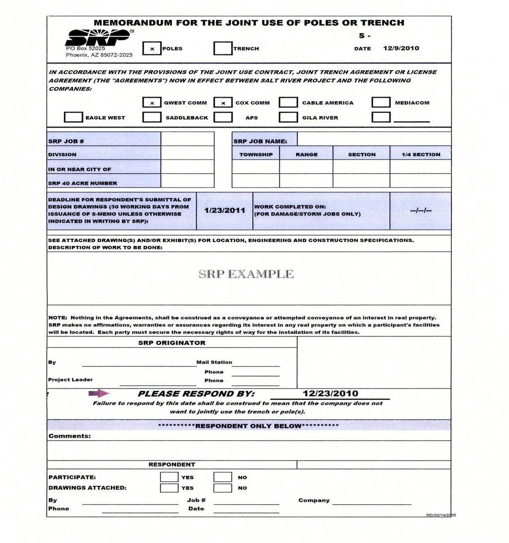
64 JNT -11-
Highway / Utility Guide
 Oregon Department of Transportation Highway Division Right of Way Section Highway / Utility Guide Railroad & Utilities Unit Right of Way Section STATEMENT OF PURPOSE It is important to understand that
ADMINISTRATIVE DIRECTIVE #CS-04
 HILLSBOROUGH COUNTY Office of the County Administrator ADMINISTRATIVE DIRECTIVE #CS-04 SUBJECT: EFFECTIVE DATE: UTILITY COORDINATION PROCEDURES FOR HILLSBOROUGH COUNTY CONSTRUCTION PROJECTS WITHIN COUNTY
UTILITY COORDINATION FOR CAPITAL IMPROVEMENTS PROJECTS
 DIVISION V SECTION 5900 UTILITY COORDINATION FOR CAPITAL IMPROVEMENTS PROJECTS Best Management Practices (March 17, 2010) APWA 5900 March 2010 DIVISION V DESIGN CRITERIA 5900 Utility Coordination for Capital
Project Planning and Development Process
 Project Planning and Development Process The project development process (PDP) involves hundreds of tasks. Many of these are internal agency activities that help an agency follow a methodical process of
Florida Cleanroom Systems
 Florida Cleanroom Systems Design Build Projects / Project Quality Control Plan (PQCP) Quality Control / Quality Assurance Manual May 2010 1 TABLE OF CONTENTS Section 1: Introduction 3 1.1 Defining Plan
Enterprise Parkway Improvement Project, CIP# E364
 Exhibit A SCOPE OF SERVICES AND FEES This project, in general, consists of: Construction of roadway improvements to extend Enterprise Parkway east of Superior Industries and Lockheed Martin to connect
SECTION MAINTENANCE OF EXISTING CONDITIONS
 SECTION 02 01 00 MAINTENANCE OF EXISTING CONDITIONS PART 1 GENERAL 1.1 GENERAL A. The CONTRACTOR shall protect all existing utilities and improvements not designated for removal and shall restore damaged
SECTION PROTECTION AND RESTORATION OF EXISTING FACILITIES
 PART 1 - GENERAL 1.1 GENERAL A. The CONTRACTOR shall protect all existing utilities and improvements not designated for removal and shall restore damaged or temporarily relocated utilities and improvements
SECTION 10 UTILITIES
 SECTION 10 UTILITIES Virtually every highway construction project in the State of New Jersey impacts utility facilities. The Designer shall examine and seek alternatives to minimize or eliminate the impact
Exhibit "A" Romoland/Homeland MDP Utility Relocations Project PROJECT COST ESTIMATE
 7/15/2014 4:11 PM Exhibit "A" Romoland/Homeland MDP Utility Relocations Project PROJECT COST ESTIMATE FACILITIES PLANNING PHASE $0 Planning Consultant $0 Eng. Branch Labor $0 PRELIMINARY DESIGN PHASE $5,000
REQUEST FOR PROPOSALS FOR. Site Civil Services for the Iowa River Landing Arena CITY OF CORALVILLE IOWA
 REQUEST FOR PROPOSALS FOR Site Civil Services for the Iowa River Landing Arena CITY OF CORALVILLE IOWA City of Coralville Iowa Coralville, IA Page 1 of 6 Please review and provide response to this letter
OPERATING POLICY MANUAL
 Page 1 of 7 Section 1. PURPOSE This policy is to explain the review process that the Bedford Regional Water Authority ( Authority ) utilizes for water and sewer developer projects planned within the service
REQUEST FOR QUALIFICATIONS
 REQUEST FOR QUALIFICATIONS Village of La Grange Phase II Design Engineering Services for Submission Deadline: No later than 10:00 am on October 19, 2018 Published on: October 5, 2018 on the Village of
EXHIBIT A SCOPE OF SERVICES FOR DISTRICTWIDE CONSULTING ENGINEERNG SERVICES STRUCTURES DESIGN
 EXHIBIT A SCOPE OF SERVICES FOR DISTRICTWIDE CONSULTING ENGINEERNG SERVICES STRUCTURES DESIGN Financial Project ID: 417069-1-32-04 Work Program Item No.: N/A Federal Aid Project ID: County/Section No.:
Construction Requirements for Installation of Utilities in the Public Right-of-way of McPherson County, Kansas October 2011
 Construction Requirements for Installation of Utilities in the Public Right-of-way of McPherson County, Kansas October 2011 General Provisions and Specifications - These provisions and specifications shall
EXHIBIT "A" SCOPE OF SERVICES CONTINUING SERVICE CONTRACT (CSC) SUBSURFACE UTILITY DESIGNATE, LOCATE AND COORDINATION. FPID No.
 SUBSURFACE UTILITY DESIGNATE, LOCATE AND COORDINATION. FPID No.") EXHIBIT "A" SCOPE OF SERVICES CONTINUING SERVICE CONTRACT (CSC) SUBSURFACE UTILITY DESIGNATE, LOCATE AND COORDINATION FPID No. TBD INDEX I. OBJECTIVES... A-1 II. SERVICES TO BE PROVIDED... A-1 A. Subsurface
EXHIBIT "A" SCOPE OF SERVICES CONTINUING SERVICE CONTRACT (CSC) SUBSURFACE UTILITY DESIGNATE, LOCATE AND COORDINATION FPID No. TBD INDEX I. OBJECTIVES... A-1 II. SERVICES TO BE PROVIDED... A-1 A. Subsurface
7. EXCAVATION IN PUBLIC STREETS The E-Permit & U-Permit
 7. EXCAVATION IN PUBLIC STREETS The E-Permit & U-Permit 7.1 E-Permit and U-Permit Permit Description and Purpose The Excavation Permit (E-Permit) and the Utility Permit (U-Permit) are issued to allow construction,
EL PASO WATER - PUBLIC SERVICE BOARD REQUEST FOR SUBMITTALS RFS June 27, 2017
 EL PASO WATER - PUBLIC SERVICE BOARD REQUEST FOR SUBMITTALS RFS 21-17 June 27, 2017 TO: RE: Invited Firms Request for Submittals to El Paso Water - Public Service Board (EPWater) Statement of Work Professional
APPLICATION FOR RIGHT OF WAY PERMIT
 City of Danville Department of Engineering & Urban Services APPLICATION FOR RIGHT OF WAY PERMIT PROJECT LOCATION: CONTRACTOR S BUSINESS NAME: CONTRACTOR'S ADDRESS: CONTRACTOR'S PHONE: OWNER S NAME: OWNER
Design -- geometric and structural design of roadways and bridges, and preparation of detailed plans and specifications for individual projects;
 WELCOME Welcome to the Estimates Chapter One Lesson. This Final Estimates training course covers the preparation of final estimates by field personnel. In this first chapter, you will become familiar with
Request for Proposals. 42nd Avenue Pump Station Rehabilitation. Public Works Department City of San Mateo 330 West 20th Avenue San Mateo, CA 94403
 42nd Avenue Pump Station Rehabilitation Public Works Department City of San Mateo 330 West 20th Avenue San Mateo, CA 94403 May 24, 2015 The City of San Mateo (City) is accepting proposals to select a qualified
DESIGNER EFFECTIVE GUIDELINES
 DESIGNER EFFECTIVE GUIDELINES Adopted by the Pennsylvania One Call System, Inc. Board of Directors January 30, 2008 Disclaimer of Liability Copyright 2008 This Guide has been prepared as an educational
TH 25 Bituminous Mill, Full Depth Reclamation and Overlay SP &
 TH 25 Bituminous Mill, Full Depth Reclamation and Overlay SP 4910-29 & 0504-14 Contract No. 1002252 Project Overview is in need of professional and technical assistance to provide detail design for State
Research Initiatives at TxDOT Related to Utilities and Right of Way
 Research Initiatives at TxDOT Related to Utilities and Right of Way Transportation Research Board Workshop on Transportation Law, New Orleans, LA July 17, 2012 Overview 2 TxDOT utility/right of way research
EXHIBIT A SCOPE OF SERVICES FOR. FINANCIAL PROJECT ID(S). Various Projects DISTRICT 2 VARIOUS COUNTIES
. Various Projects DISTRICT 2 VARIOUS COUNTIES") EXHIBIT A SCOPE OF SERVICES FOR FINANCIAL PROJECT ID(S). Various Projects DISTRICT 2 VARIOUS COUNTIES 1 PURPOSE... 3 2 PROJECT DESCRIPTION... 5 3 PROJECT COMMON AND PROJECT GENERAL TASKS... 6 4 ROADWAY
EXHIBIT A SCOPE OF SERVICES FOR FINANCIAL PROJECT ID(S). Various Projects DISTRICT 2 VARIOUS COUNTIES 1 PURPOSE... 3 2 PROJECT DESCRIPTION... 5 3 PROJECT COMMON AND PROJECT GENERAL TASKS... 6 4 ROADWAY
REQUEST FOR PROPOSALS
 REQUEST FOR PROPOSALS CONSTRUCTION MANAGEMENT SERVICES OCTOBER 09, 2014 EAST BAY REGIONAL PARK DISTRICT Atlas Road Extension Improvements POINT PINOLE REGIONAL SHORELINE PROPOSALS DUE: 2:00PM, NOVEMBER
301 Walnut Street Windsor, Colorado phone fax
 301 Walnut Street Windsor, Colorado 80550 phone 970-674-2400 fax 970-674-2456 www.windsorgov.com Table of Contents... 2 SECTION 1 Questions & Requests for Clarification... 3 1.1 Question Deadline... 3
SECTION GS10300 UNDERGROUND TRENCHING AND EXCAVATION CONSIDERATIONS
 SECTION GS10300 UNDERGROUND TRENCHING AND EXCAVATION CONSIDERATIONS PART 1 GENERAL 1.1 RELATED DOCUMENTS A. Drawings, general provisions of the contract, including General and Supplementary Conditions
Task Order Authorization
 Task Order Authorization Task Order Number: 6 Task Order Name: 2017 Small Drainage Program Hourly Rate: See attached Exhibit B Budget Not To Exceed: $79,795.00 This Task Order pertains to the On-Call Agreement
CHAPTER 7 - INFRASTRUCTURE INSPECTION AND ACCEPTANCE... 2
 CHAPTER 7 - INFRASTRUCTURE INSPECTION AND ACCEPTANCE... 2 7.1. GENERAL.... 2 7.1.1. Inspection Restriction Dates.... 2 7.1.2. Complete Improvements.... 2 7.1.3. Public Improvements.... 2 7.1.4. Warranty
Step 1. Determine if a Small Utility GESC Permit is Applicable and if a Project Specific GESC Plan is Required.
 Overview of Section 9 9.0 The GESC Permit Section provides a description of the Small Utility GESC Permit Program. Step 1. Determine if a GESC Permit is Applicable and if a Project Specific GESC Plan is
APPENDIX D CONSTRUCTION PHASE CRITERIA
 A. GENERAL REQUIREMENTS CONSTRUCTION PHASE CRITERIA For the Construction Phase of the Project, the Architect/Engineer (A/E) is responsible for providing project administration for the Owner in accordance
NORFOLK SOUTHERN RAILWAY COMPANY FILES: BR & BR
 NORFOLK SOUTHERN RAILWAY COMPANY FILES: BR0013844 & BR0013846 CHARLESTON, CHARLESTON COUNTY, SOUTH CAROLINA CHARLESTON PORT ACCESS ROADWAY PROJECT (1) SITE - 1 - REPLACEMENT OF EXISTING US78/52 OVERHEAD
Public Works and Utilities Department RIGHT-OF-WAY USE PERMIT APPLICATION
 RIGHT-OF-WAY USE PERMIT APPLICATION INSTRUCTIONS 1. The Engineering Section of the City of Bradenton Department of Public Works and Utilities is responsible for processing and approving all ROW Use Permits.
APPENDIX A DEFINITION OF PROFESSIONAL ENGINEERING CONSULTING SERVICES
 Appendix A RFP No. 894-2014 Page 1 of 1 Template Version: SrC120131129 - Consulting Services RFP APPENDIX A DEFINITION OF PROFESSIONAL ENGINEERING CONSULTING SERVICES Revision: 2014-09-22 DEFINITION OF
DESIGN CRITERIA PACKAGE FOR A DESIGN/BUILD OF THE CITY OF LYNN HAVEN SRF WATER AND WASTEWATER IMPROVEMENTS PROJECTS
 DESIGN CRITERIA PACKAGE FOR A DESIGN/BUILD OF THE CITY OF LYNN HAVEN SRF WATER AND WASTEWATER IMPROVEMENTS PROJECTS PREPARED FOR: Margo Anderson, Mayor Antonius Barnes, Commissioner Judy Tinder, Commissioner
CHECKLIST FOR STREETS, INLETS, AND STORM SEWER DESIGN
 CHECKLIST FOR STREETS, INLETS, I. STREET CLASSIFICATION AND DESIGN CRITERIA A. Determine drainage classification for the roadway section using Table 7-1 or Table 7-2. B. Determine the allowable flow depth
CONSTRUCTION PROCEDURES HANDBOOK
 CONSTRUCTION PROCEDURES HANDBOOK SECTION VI SUBSECTION K DATE CONSTRUCTION OPERATIONS UTILITY COORDINATION 1. Utility Agreements Utility Agreements Modifications (UAMs) authorizing utility construction
Request for Proposals. Hillsdale Pedestrian/Bicyclist Bridge Design
 Request for Proposals Hillsdale Pedestrian/Bicyclist Bridge Design Public Works Department City of San Mateo 330 West 20th Avenue San Mateo, CA 94403 JUNE 13, 2013 The City of San Mateo (CITY) is accepting
DEPARTMENT OF MUNICIPAL AFFAIRS AND ENVIRONMENT MUNICIPAL INFRASTRUCTURE PROJECT GUIDELINES
 DEPARTMENT OF MUNICIPAL AFFAIRS AND ENVIRONMENT MUNICIPAL INFRASTRUCTURE PROJECT GUIDELINES It is essential for the municipality and also the municipal engineer or prime consultant to comply with the following
City of Santaquin REQUEST FOR PROPOSALS For Engineering Services for the East Side Booster Pump Station
 City of Santaquin REQUEST FOR PROPOSALS For Engineering Services for the East Side Booster Pump Station The City of Santaquin (the City ) hereby requests competitive proposals from qualified consultants
SECTION CONSTRUCTION SERVICES
 SECTION 01100 CONSTRUCTION SERVICES PART 1 GENERAL 1.01 - Section Includes A. Mobilization. B. Construction Surveys. C. Record Documents. 1.02 Description Of Work A. Mobilization: includes the preparatory
LANDS ROW MANAGEMENT AND TRANSMISSION ENGINEERING UNIFORM STANDARDS INDEX. 1. Plan Submittal, Review & Approval Page 3
 LANDS ROW MANAGEMENT AND TRANSMISSION ENGINEERING UNIFORM STANDARDS INDEX 1. Plan Submittal, Review & Approval Page 3 1.1 Plan Submittal Review Page 3 1.2 Approval Types Page 4 1.2.1 No Conflict Process
Chapter 5. Utilities
 Chapter 5 Utilities 5.1 General...5-1 5.2 Utility Accommodation Manual...5-2 5.3 Location of Existing Utilities...5-3 5.3.1 Quality Levels of Utility Locates...5-3 5.4 Subsurface Utility Engineering...5-5
CITY OF HOMESTEAD Utility Rights-of-Way Use Permit Application
 CITY OF HOMESTEAD Utility Rights-of-Way Use Permit Application Good for 90 days from the Date Issued This permit is only required if the work location is owned or controlled by the City of Homestead and
Section 200 Design Process and Quality Management. Electrical Engineering Centre
 Section 200 Design Process and Quality Management Electrical Engineering Centre April 2013 TABLE OF CONTENTS 200 DESIGN PROCESS AND QUALITY MANAGEMENT 201 INTRODUCTION TO DESIGN PROCESS... 1 201.1 ABOUT
FOOTING DRAIN DISCONNECTION PROGRAM GUIDELINES
 FOOTING DRAIN DISCONNECTION PROGRAM GUIDELINES In September of 2010, the City of Grand Rapids amended its Sewage Disposal System Ordinance by adopting an Article entitled, Footing Drain Disconnection Program
York County Engineering Department Roadway Inspection Requirements
 York County Engineering Department Roadway Inspection Requirements The following is a list, in order, of the roadway inspections that are required to be passed by York County before a subdivision can receive
PennDOT Pub. 170 Highway Occupancy Permit (HOP) Manual Page 56
 Manual Page 56") PennDOT Pub. 170 Highway Occupancy Permit (HOP) Manual Page 56 Additional Fees Additional fees may be charged by PennDOT consistent with Sections 411 and 420 of the State Highway Law and Regulations 441.4(d)
PennDOT Pub. 170 Highway Occupancy Permit (HOP) Manual Page 56 Additional Fees Additional fees may be charged by PennDOT consistent with Sections 411 and 420 of the State Highway Law and Regulations 441.4(d)
AMENDMENT TO THE PERSONAL SERVICES AGREEMENT Amendment No. 6 Agreement # / Project Number: 1TGCI
 AMENDMENT TO THE PERSONAL SERVICES AGREEMENT Amendment No. 6 Agreement # 106204/31700124 Project Number: 1TGCI This Amendment No. 6 to Personal Services Agreement is entered into effective between the
ATTACHMENT D SCOPE OF SERVICES
 ATTACHMENT D SCOPE OF SERVICES OBJECTIVE Owner s Capital Improvement Program (major capital, minor construction, repair, and rehabilitation projects) includes numerous construction and renovation projects.
Transportation Contributed Assets Review January 28, 2015
 Transportation Contributed Assets Review January 28, 2015 Office of the City Auditor The Office of the City Auditor conducted this project in accordance with the International Standards for the Professional
Request for Qualifications: City Engineering and Architectural Services
 Request for Qualifications: City Engineering and Architectural Services The City of Clever, Missouri ( City ) is pleased to issue this Request for Qualifications ( RFQ ) for City Engineering and Architectural
REQUEST FOR PROPOSALS For Engineering Design Services Street Reconstruction at Various Locations CITY OF SAN MATEO, CALIFORNIA
 REQUEST FOR PROPOSALS For Engineering Design Services Street Reconstruction at Various Locations CITY OF SAN MATEO, CALIFORNIA The City of San Mateo hereby requests proposals for engineering design services
REQUEST FOR PROPOSALS. Construction Manager CM Services Pre-Construction and Construction Services
 REQUEST FOR PROPOSALS Construction Manager CM Services Pre-Construction and Construction Services Big Sky Fire Department Station 1 Project Big Sky Fire District OWNER Big Sky, Montana November 2016 Request
Exhibit A Mn/DOT Contract No
 Exhibit A Mn/DOT Contract No. 98142 SCOPE OF WORK AND DELIVERABLES Preliminary Design Red Wing US 63 Bridge and Approach Roadways State Project (SP) 2515-21 SCOPE OVERVIEW... 2 SCHEDULE... 2 PROJECT TASK
I. Project Overview and Limits. Project Goal
 Scope of Work and Deliverables for Subsurface Utility Engineering (SUE) for both Underground and Overhead Utilities on T.H. 10, and its Connecting Roads under S.P. 8001-40 I. Project Overview and Limits
York County Engineering Department Roadway Inspection Requirements
 York County Engineering Department Roadway Inspection Requirements The following is a list, in order, of the roadway inspections that are required to be passed by York County before a subdivision can receive
Document B Standard Form of Agreement Between Owner and Architect, Construction Manager as Adviser Edition
 Document B132 2009 Standard Form of Agreement Between Owner and Architect, Construction Manager as Adviser Edition AGREEMENT made as of the in the year (In words, indicate day, month and year.) BETWEEN
TERMS OF REFERENCE PROJECT EDINBURGH ROAD FROM SPEEDVALE AVENUE TO LONDON ROAD
 TERMS OF REFERENCE PROJECT EDINBURGH ROAD FROM SPEEDVALE AVENUE TO LONDON ROAD OBJECTIVES/PURPOSE The City of Guelph intends to upgrade the underground services to current standards and carry out complete
Construction Documents Checklist
 Construction Documents Checklist The following must be completed prior to final approval of site development plans (Construction Documents) by the Town: Final Drainage Report signed by engineer-of-record
EL PASO WATER - PUBLIC SERVICE BOARD REQUEST FOR SUBMITTALS RFS February 5, 2019
 EL PASO WATER - PUBLIC SERVICE BOARD REQUEST FOR SUBMITTALS RFS 25-19 February 5, 2019 TO: RE: Invited Firms Request for Submittals to El Paso Water - Public Service Board (EPWater) Statement of Work Professional
GUIDE TO PREPARING BID DOCUMENTS FOR PRIVATE INITIATIVE PROJECTS.
 N A T I O N A L C O N C E S S I O N C O U N C I L GUIDE TO PREPARING BID DOCUMENTS FOR PRIVATE INITIATIVE PROJECTS. PREPARED BY: ENGINEER ÁLVARO BORBON M. PRIVATE INITIATIVE PROGRAM DECEMBER 2008 INDEX
A.1 WATER SYSTEM PLAN SUBMITTAL PROCEDURES AND GENERAL REQUIREMENTS
 PC Plan Submittal and Review A.1 WATER SYSTEM PLAN SUBMITTAL PROCEDURES AND GENERAL REQUIREMENTS All plans for water main extensions, improvements and modifications shall be submitted to the District manager.
Oklahoma Underground Facilities Damage Prevention Act
 Oklahoma Underground Facilities Damage Prevention Act For your reference a copy of the act has been included in this guide. The act may be changed at any time and you should contact Oklahoma One-Call System,
MONTGOMERY STREET. Construction Manager at Risk (CMAR) Services
 Services") 2 nd PRE-PROPOSAL CONFERENCE March 6, 2015 MONTGOMERY STREET (City Project #02432) Construction Manager at Risk (CMAR) Services PROCUREMENT MARCH 19, 2015 1 Michael Weiss, P.E. City of Fort Worth Project
2 nd PRE-PROPOSAL CONFERENCE March 6, 2015 MONTGOMERY STREET (City Project #02432) Construction Manager at Risk (CMAR) Services PROCUREMENT MARCH 19, 2015 1 Michael Weiss, P.E. City of Fort Worth Project
REQUEST FOR PROPOSAL ARCHITECTURAL & ENGINEERING SERVICES OTTAWA COUNTY ROAD COMMISSION COOPERSVILLE AREA MAINTENANCE COMPLEX
 REQUEST FOR PROPOSAL ARCHITECTURAL & ENGINEERING SERVICES OTTAWA COUNTY ROAD COMMISSION COOPERSVILLE AREA MAINTENANCE COMPLEX The Ottawa County Road Commission is seeking the submittal of written proposals
Town of Brandon, Vermont Brandon Union St. Sidewalk STP EH 05 (4) Request for Qualifications Construction Inspection and Testing Services
 Request for Qualifications Construction Inspection and Testing Services") , Vermont Brandon Union St. Sidewalk STP EH 05 (4) Request for Qualifications Construction Inspection and Testing Services Issued: March 13, 20192 Due: April 3, 2019 I. INTRODUCTION The, Vermont, herein
, Vermont Brandon Union St. Sidewalk STP EH 05 (4) Request for Qualifications Construction Inspection and Testing Services Issued: March 13, 20192 Due: April 3, 2019 I. INTRODUCTION The, Vermont, herein
Lincoln City Visitor and Convention Bureau. City of Lincoln City REQUEST FOR QUALIFICATIONS
 Lincoln City Visitor and Convention Bureau City of Lincoln City REQUEST FOR QUALIFICATIONS Visitor Center Concept Development and Designs Architectural Services Lincoln City, Oregon April 20, 2018 RFQ
Stormwater Utility Manual City of Racine, Wisconsin
 Stormwater Utility Manual City of Racine, Wisconsin TABLE OF CONTENTS Section 1 STORMWATER UTILITY ORDINANCE SECTION 98-201 2 STORMWATER UTILITY RATE RESOLUTION 3 STORMWATER UTILITY CREDITS RESOLUTION
FLORIDA DEPARTMENT OF TRANSPORTATION
 FLORIDA DEPARTMENT OF TRANSPORTATION ADDENDUM NO. 2 DATE: December 28, 2011 RE: RFP NUMBER: RFP TITLE: ITS Equipment Replacement in Broward County OPENING OF TECHNICAL PROPOSAL DATE: January 5, 2012 Notice
PROCEDURES FOR FIBER OPTIC CABLE PERMITS REVISED: OCTOBER 18, 2018
 JIM STRICKLAND MAYOR ENGINEERING DIVISION PROCEDURES FOR FIBER OPTIC CABLE PERMITS REVISED: OCTOBER 18, 2018 CITY OF MEMPHIS 125 N. Main St., Memphis TN 38103 Table of Contents I Introduction & General
6 UTILITIES. 6.1 General. 6.2 Administrative Requirements Initial Allocation of Responsibility Design-Builder
 6 UTILITIES 6.1 General The Design-Builder shall conduct all Utility Work in accordance with the Contract Documents. Except as otherwise provided in the Contract Documents, Betterments are not included
1006 UTILITIES, STREET LIGHTS, WATER SUPPLY, SEWAGE DISPOSAL, SURFACE WATER MANAGEMENT, AND EROSION CONTROL
 1006 UTILITIES, STREET LIGHTS, WATER SUPPLY, SEWAGE DISPOSAL, SURFACE WATER MANAGEMENT, AND EROSION CONTROL 1006.01 GENERAL STANDARDS A. The location, design, installation, and maintenance of all utility
Town of Brandon, Vermont US Route 7 (Center Street) Segment 6 Improvements NH 019-3(496) Request for Qualifications
 Segment 6 Improvements NH 019-3(496) Request for Qualifications") , Vermont US Route 7 (Center Street) Segment 6 Improvements NH 019-3(496) Request for Qualifications Construction Inspection Services Issued: January 18, 2017 Due: February 8, 2017 I. INTRODUCTION The,
, Vermont US Route 7 (Center Street) Segment 6 Improvements NH 019-3(496) Request for Qualifications Construction Inspection Services Issued: January 18, 2017 Due: February 8, 2017 I. INTRODUCTION The,
CHAPTER 12 INSTALLATION OF UTILITIES AND OTHER SYSTEMS TABLE OF CONTENTS
 CHAPTER 12 INSTALLATION OF UTILITIES AND OTHER SYSTEMS TABLE OF CONTENTS Section Title Page 12.1 General... 12-1 12.2 Design Standards... 12-1 12.2.1 General Requirements...12-1 12.2.2 Minimum Depth...12-1
Rte. 66/29 Interchange Reconstruction Project: ,C505 Grade Separation of Two Crossings Norfolk Southern Railway Right of Way and Track
 Rte. 66/29 Interchange Reconstruction Project: 0066-076-113,C505 Grade Separation of Two Crossings Norfolk Southern Railway Right of Way and Track Mileposts B-8.1 thru B-8.8 DOT 714-363S, 714-364Y Gainesville,
1997 Part 2. Document B141. Standard Form of Architect's Services: Design and Contract Administration TABLE OF ARTICLES
 TM Document B141 Standard Form of Architect's Services: Design and Contract Administration 1997 Part 2 TABLE OF ARTICLES 2.1 PROJECT ADMINISTRATION SERVICES 2.2 SUPPORTING SERVICES 2.3 EVALUATION AND PLANNING
Request for Proposals for the analysis of Tax Increment Financing in Indiana
 Request for Proposals for the analysis of Tax Increment Financing in Indiana June 29, 2015 TABLE OF CONTENTS Overview... 2 Project Overview... 2 Scope of Work... 3 Task #1 Opportunity & Discovery... 3
1-0 Planning and Design Best Practices. 1 Planning and Design
 1-0 Planning and Design Best Practices 1 Planning and Design 1-0 Planning and Design Best Practices 1-1: Planning Utility Corridors Practice Statement: Designers and planners should evaluate all applicable
RIGHT-OF-WAY PERMIT SUBMITTAL CHECKLIST
 RIGHT-OF-WAY PERMIT SUBMITTAL CHECKLIST Email all ROW applications to digitalpermits@cityoforlando.net In the subject line, please include ROW *More information may be required since every project is unique.
1. INTRODUCTION 1.1 Contents of Engineering Specifications The Engineering Specifications contains the following sections:
 Schedule H to Bylaw 7452, Subdivision Bylaw Page 1 1. INTRODUCTION 1.1 Contents of Engineering Specifications 1.1.1 The Engineering Specifications contains the following sections: 1. Introduction 2. General
REQUEST FOR PROPOSALS FOR PROFESSIONAL ENGINEERING SERVICES FOR DESIGN OF RECHARGE BASIN ON VICTORIA SITE
 REQUEST FOR PROPOSALS FOR PROFESSIONAL ENGINEERING SERVICES FOR DESIGN OF RECHARGE BASIN ON VICTORIA SITE General Provisions Western Municipal Water District (WMWD) requests a qualified Design Consultant
REQUEST FOR PROPOSALS AND STATEMENT OF QUALIFICATIONS IMPACT FEE STUDY
 REQUEST FOR PROPOSALS AND STATEMENT OF QUALIFICATIONS IMPACT FEE STUDY June 1, 2018 The City of Rhome is now accepting sealed Request for Proposals and Statement of Qualifications (RFQ) for New Water &
REQUEST FOR QUALIFICATIONS
 REQUEST FOR QUALIFICATIONS PROJECT: ISSUE DATE: October 22, 2018 ISSUED BY: INQUIRIES: SUBMISSION DEADLINE: SUBMIT TO: City of Delaware, Ohio Public Works Department, Traffic & Engineering Services 440
ALTERNATIVE PROJECT DELIVERY DIVISION
 VIRGINIA DEPARTMENT OF TRANSPORTATION ALTERNATIVE PROJECT DELIVERY DIVISION INSTRUCTIONAL AND INFORMATIONAL MEMORANDUM GENERAL SUBJECT: Design-Build Requirements for Advertisement SPECIFIC SUBJECT: APPROVED:
AGENDA March 26, :30 P.M. City Council Chambers
 03-26-12 Committee of the Whole Meeting http://www.darien.il.us/government/minutes/2012/council/120326/age... 1 of 1 1/19/2015 9:26 PM AGENDA March 26, 2012 6:30 P.M. City Council Chambers 1. CALL TO ORDER
PLANNING AND EVALUATION PRELIMINARY DESIGN
 PLANNING AND EVALUATION Project Initiation Discuss and refine client requirements Project brief, Schedule, Budget Confirm client's space needs and program Establish scope of work Obtain client-supplied
Chapter 3: Permit Procedures and Requirements
 Chapter 1: General Provisions 1 1 Short Title 1 2 Jurisdiction 1 3 Amendments and Revisions 1 4 Enforcement Responsibility 1 5 Review Process 1 6 Prior Approval 1 7 Relationship to Other Standards 1 8
Purchasing and Procurement Policy
 Purchasing and Procurement Policy Purpose The purpose of this document is to implement the requirements of state law with regard to procurement and bidding on public contracts for public works, goods,
600 - Phase C Intermediate Review Checklist for the Architect- Engineer
 600 Phase C Intermediate Review Checklist for the Architect Engineer This checklist is to be used by the ArchitectEngineer during Phase C of the Project and shall be included in the Intermediate Review
Phase 2 Exposition Metro Line Project
 Phase 2 Exposition Metro Line Project Monthly Project Status Report April 2013 TABLE OF CONTENTS PHASE 2 EXPO LINE PROJECT STATUS TABLE OF CONTENTS... 2 Phase 2 Exposition Metro Line Construction Authority
DUKE UNIVERSITY CONSTRUCTION STANDARDS
 1 23 08 00 Commissioning of HVAC Systems 1. GENERAL A. GENERAL PROVISIONS 1. Drawings and general provisions of the Contract, including General Conditions and Division - 1 Specifications Sections, apply
CHAPTER 5: UTILITIES
 CHAPTER 5: UTILITIES GENERAL UTILITY INFORMATION Experience shows that proactive utility coordination early in the design of a project minimizes the amount of effort needed later in the design life and
STATE OF NEW JERSEY DEPARTMENT OF ENVIRONMENTAL PROTECTION DIVISION OF COASTAL ENGINEERING
 INDEX OF DRAWINGS SHEET NO. DESCRIPTION 1 TITLE SHEET AND LOCATION PLAN 2 GENERAL NOTES AND SITE ACCESS AND STAGING AREA LAYOUT 3 EXISTING CONDITIONS AND DEMOLITION PLAN 4 CONSTRUCTION PLAN AND PROFILE
SPECIAL SPECIFICATION 6664 Level (3) Communications System
 Communications System") 2004 Specifications CSJ 1200-05-014 SPECIAL SPECIFICATION 6664 Level (3) Communications System 1. Description. A. This Item will govern the installation of all facilities belonging to Level (3) Communications,
2004 Specifications CSJ 1200-05-014 SPECIAL SPECIFICATION 6664 Level (3) Communications System 1. Description. A. This Item will govern the installation of all facilities belonging to Level (3) Communications,
SPECIAL SPECIFICATION 6658 Time Warner Communications System
 2004 Specifications CSJ 1200-05-014 1. Description. SPECIAL SPECIFICATION 6658 Time Warner Communications System A. This Item will govern the installation of all facilities belonging to Time Warner Cable
Creating a NEW Foundation for the NEXT Generation of Transportation Initiatives The Morphing of the Role of a Utility Project Manager
 Controls Conference - Hyatt Regency Savannah, Georgia - April 14-18, 2013 Creating a NEW Foundation for the NEXT Generation of Transportation Initiatives The Morphing of the Role of a Utility Project Manager