Ground Improvement Techniques: Dynamic Compaction Martin Larisch & Tim Pervan
|
|
|
- Griffin Hunt
- 6 years ago
- Views:
Transcription
1 Ground Improvement Techniques: Dynamic Compaction Martin Larisch & Tim Pervan INSERT DATE HERE

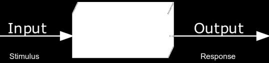
2 Ground Improvement - What is it? Ground Improvement = Black Box?
3 Ground Improvement - Introduction Ground Improvement Improve the existing soil formation by changing the soil properties by mechanical or chemical treatment. Ground improvement doesn t create structural elements (like piles) to bridge unsuitable soil layers but it improves the ground itself to allow for shallow foundations. Ground improvement is mainly used for: - Settlement reduction / control - Liquefaction mitigation

4 Fletcher Construction Company


5 Brian Perry Civil Established in1954 in Hamilton Head office today in Auckland (Penrose). Branches in: - Hamilton - Auckland - Christchurch - Wellington

6 Brian Perry Civil Four branches around New Zealand 350 employees (80 engineers) Turnover $230m Hamilton Auckland Our Focus Self performing, high-risk civil engineering contracting Projects up to $50m Smart use of technology Drive innovation and strong client focus Christchurch Wellington


7 Areas of Expertise
8 Ground Improvement - Methods Overview of some ground improvement methods: Vibro compaction Vibro replacement Soil mixing Jet grouting Deep soil mixing (vertical) Deep soil mixing (horizontal / block) Rigid Inclusions Dynamic replacement Dynamic compaction
 is a cost")

9 Vibro Compaction (VC) - Introduction Vibro compaction (VC) is a cost effective GI method which allows to specifically target deeper treatment areas.

10 Vibro compaction (VC) - Introduction Vibro compaction
 Suitable")
11 Vibro Compaction (VC) Suitable Soils
 Suitable")
12 Vibro compaction (VC) Suitable Soils
13 Vibro replacement (VR) vs Vibro compaction (VC)
 -")
")
14 Vibro replacement (VR) - Introduction Vibro replacement (wet top feed)

15 Vibro replacement (VR) - Introduction Vibro replacement (dry bottom feed)
 Suitable")
16 Vibro replacement (VR) Suitable Soils
 Lateral movements (VR probe) Different performance in similar (granular) ground")
17 Vibro replacement (VR) Methods - CAUTION Methodologies: Vertical movements (sheet piling probe) Lateral movements (VR probe) Different performance in similar (granular) ground conditions

18 Deep Soil Mixing (DSM) - Introduction Deep Soil Mixing (DSM)
 - vertical")
19 Deep Soil Mixing (DSM) - Introduction Deep Soil Mixing (DSM) - vertical columns
20 Deep Soil Mixing (DSM) - Vertical columns Good mixing quality also in plastic clay Precise diameter and good verticality High production rates By limiting the jetting pressures, the cement content, the resulting column strength and the column modulus are relatively constant Column diameter: 600 to 1000 mm Column depth: typically up to 15m, greater depths are possible depending on rig size, soil properties, column diameter and consistency Column strengths between 0.5 MPa and 2 MPa are typical, depending on ground conditions, mixing time and cement content
 -")

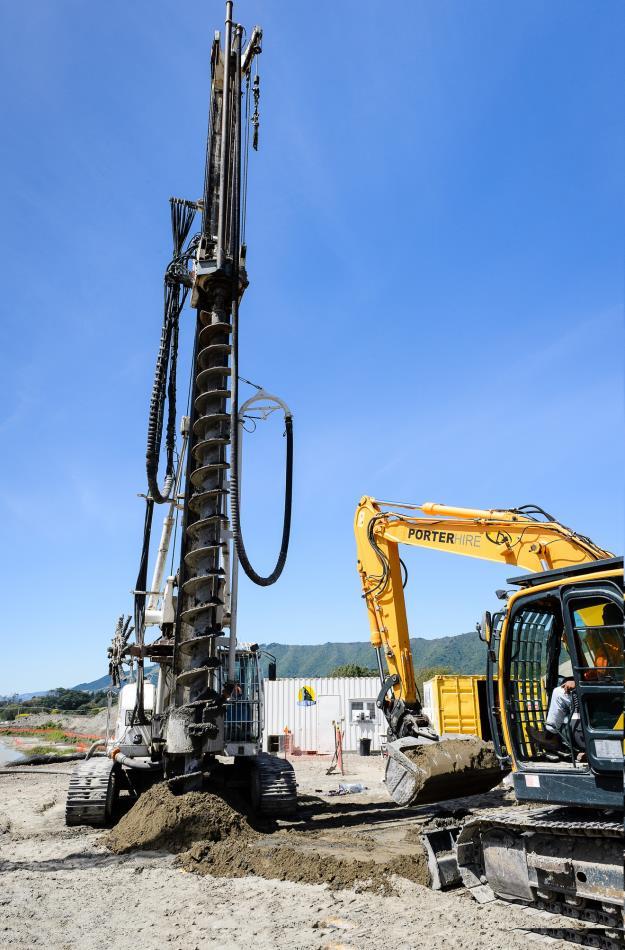
21 Continuous Flight Auger (CFA) - Introduction CFA lattice structures - vertical columns
")

22 Deep Soil Mixing (DSM) - Introduction Deep Soil Mixing (DSM) - mass mixing
23 Deep Soil Mixing (DSM) - Mass mixing Good mixing quality in granular soils High production rates The cement content, the resulting soilcrete strength and the soilcrete modulus are relatively constant Panel width: 600 to 1500 mm Panel depth: typically up to 5m, greater depths are possible depending on rig size, soil properties Soilcrete strengths between 0.5 MPa and 2 MPa are typical, depending on ground conditions, mixing time and cement content
 methods Innovative methodology with potential for liquefaction")
24 Rigid Inclusions (RI) - Introduction Rigid Inclusions with Drilled Displacement Piling (DDP) methods Innovative methodology with potential for liquefaction mitigation
 methods")

25 Rigid Inclusions (RI) - Installation effects Rigid Inclusions with Drilled Displacement Piling (DDP) methods Installation effects are critical for soil densification! Working platform Working platform Liquefiable layer Liquefiable layer
26 Rigid Inclusions (CMC, CSC, DDP) - Introduction Densification potential in loose granular soils if penetration rate is sufficient and auger geometry is suitable Penetration of hard layers possible High production rates The use of concrete (usually 5 to 15 MPa) keeps the column modulus very constant Column diameters: 450mm to 900 mm for non-displacement techniques 360mm to 450mm for drilled displacement techniques Column depth: typically up to 25m, greater depths are possible depending on rig size, soil properties

27 Dynamic Compaction (DC) - Introduction Dynamic compaction (DC) is a cost effective and efficient method for ground improvement works.
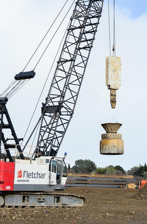
28 Dynamic Compaction (DC) - Introduction Dynamic compaction (DC) strengthens weak soils by controlled highenergy tamping (dropping a static weight from a defined height). The reaction of the soil during the treatment varies with soil type and energy input. Typically drop weights range from 6-20 ton dropped from heights up to 20m. Weights are typically constructed using steel plates, box steel and concrete (also suitably reinforced mass concrete).


 is")

29 Dynamic Replacement (DR) - Overview Dynamic replacement (DR) is another cost effective GI method.

30 Dynamic Compaction (DC) - Introduction Dynamic compaction (DC) is applied in different passes to improve the ground efficiently: - Pass 1: deep treatment - Pass 2: intermediate treatment - Pass 3: shallow treatment

31 Dynamic Compaction (DC) - Introduction Dynamic compaction (DC) is applied in different passes to improve the ground efficiently: - Pass 1: deep treatment - Pass 2: intermediate treatment - Pass 3: shallow treatment

32 Dynamic Compaction (DC) - Introduction Dynamic compaction (DC) is applied in different passes to improve the ground efficiently: - Pass 1: deep treatment - Pass 2: intermediate treatment - Pass 3: shallow treatment
33 Dynamic Compaction (DC) - Design requirements It is important to understand the design requirements of your project in order to determine the best treatment / solution: - Bearing capacity - Settlement improvement - Liquefaction mitigation - Long term performance - Other (e.g. backfilling landfill sites or collapsing cavities) Is a load transfer / distribution layer required?
34 Dynamic Compaction (DC) - Suitable soil groups Soil groups (typically) suitable for treatment by Dynamic Compaction General Soil Type Degree of Saturation Suitability for DC Granular deposits in the grain size range of boulders to sand with 0% passing the 0.074mm sieve Granular deposits containing not more than 35% silts Semi-permeable soil deposits, generally silty soils containing some sands but less than 25% clay with PI<8 Impermeable soil deposits generally clayey soils where PI>8 Miscellaneous fill including paper, organic deposits, metal and wood High or Low High Low High Low High Low Low Excellent Good Excellent Fair Good Not Recommended Fair-minor improvements water content should be less than plastic limit Fair-long term settlement anticipated due to decomposition. Limit use to embankments Highly organic deposits peat-organic silts High Not recommended unless sufficient energy applied to mix granular with organic soils
35 Working principle - Granular soils In dry granular materials tampering improves engineering properties of the soil. Physical displacement of particles and low-frequency excitation will: - reduce the void ratio and - increase the relative density to provide improved load bearing and enhanced settlement criteria. The existing density and grading of the soil are major factors how efficiently a granular soil deposit can be improved.
36 Working principle - Granular soils (high energy) Below the ground water table and after a suitable number of surface impacts, pore pressure rises to a sufficient level to introduce liquefaction. Low frequency vibrations caused by further stress impulses will then re-organise the particles into a denser state. Dissipation of pore water pressures in conjunction with the effective surcharge of the liquefied layer by the soils above, results in further increase in relative density over a relatively short time period. (1-2 days in well graded sands to 1-2 weeks in silty sands)
37 Working principle - Granular soils (low energy) DC can be used without inducing the liquefied state (which is almost impossible in loose sandy deposits with high ground water tables ) The treatment without liquefaction is aimed to provide compaction by displacement without dilation or high excess pore pressure by using a smaller number of drops from a lower drop height. This approach, where applicable, requires significantly lower energy input than the liquefaction approach with consequent economies.

38 Volumetric response of granular soils Typical volumetric response of granular soil treated by DC
39 Working principle - Cohesive soils The mechanism for achieving improvements of: - cohesive natural soils, - soft near-saturated clay fill or - recent hydraulically placed fill is more complex than that of granular soils. With conventional consolidation theory, a static surcharge loading will collapse voids within clay fills and expel water to induce consolidation and increase strength. The rate at which this occurs is dependent upon the imposed load, coefficient of consolidation, and length of drainage path.
40 Working principle - Cohesive soils In contrast, dynamic compaction applies a virtually instant localised surcharge that collapses voids and transfers energy to the pore water. This creates zones of a positive water pressure gradient that forces water to rapidly drain from the soil matrix. This effect is accelerated further by the formation of additional drainage paths through shear and hydraulic failure of the soil as the weight hits the ground. Consolidation therefore occurs more rapidly and literally squeezes the water out of the soil to effectively pre-loading the ground.
41 Working principle - Cohesive soils The treatment of cohesive soil above the ground water table can lead to significant improvements in bearing capacity. Cohesive soils below the ground water table, a larger reduction of the moisture content is required in the presence of a smaller available pore-pressure gradient and a longer drain path. Only nominal degrees of improvement have been achieved in thick layers of relatively weak saturated clays and silts, even with additional measures like wick drains, stone columns or aggregate filled trenches.
42 Volumetric response of cohesive soils Typical volumetric response of cohesive soil treated by DC

43 Dynamic Compaction (DC) - Depth of treatment Menard originally proposed that the effective depth of treatment was related to the metric energy input expressed as D = K WH. Where W is the weight in tonnes, H the drop height in meters, and K is the modification factor for soil type
44 Dynamic Compaction (DC) - Depth of treatment It is important to understand the project requirements as kinetic energy impact at the point of treatment is critical in depth treatment and increasing the drop height will increase the velocity. The shape of the improvement in the ground tends to be similar to the Boussinesq distribution of stress for a circular foundation. Modification of energy levels at each tamping pass can be used to custom-design the treatment scheme to a specific soil profile and engineering requirement.
45 Dynamic Compaction (DC) - Depth of treatment The figure below suggests that factors as high as 0.9 could apply for shallow depths of loose granular soils (typical values are lower)
46 Dynamic Compaction (DC) - Quality control It is normal procedure to test treated ground during the progress of the compaction works for control purposes to assess the effectiveness of the treatment. This provides the designer with assurance that the specified level of compaction will achieve the degree of improvement required. Quality control testing during treatment often involves in-situ penetration tests (e.g. CPT or SPT) which may form part of the final assurance testing. Test methods, frequency of testing and criteria for acceptance should be agreed at tender stage. The frequency of testing will be affected by factors particular to each project, for example, the variability of the ground before treatment, the nature of the structure to be supported and its sensitivity to post-treatment movements.
47 Ground Improvement - Summary - It is important to fully understand the design requirements - It is important to understand the ground improvement methodology and it s specific advantages and limitations - Dynamic compaction can be very effective in granular soils - High energy - Low energy - Dynamic compaction can be used with caution in cohesive soils and soils with organic layers - Noise and vibration effects of different ground improvement techniques must be considered and how these can be managed - New technologies offer greater opportunities and unknown risks


48 Project Example M2PP Alliance


49 DC Project Example M2PP MacKay s to Peka Peka Expressway 18km Long 4 lane expressway 15 road bridges the longest being 250m across the Waikanae River 2 significant pedestrian overpass bridges Project Value = $600M NZD


50 M2PP Geology and Seismicity Design PGA up to 0.98g in a 1/2500 year ULS event. Extensive sections underlain by potentially liquefiable dune sands and silts


51 M2PP Geology and Seismicity Approximately 50% of the earthwork footprint is underlain by peat. Ground water levels are near surface


52 Design Requirements Displacement based design adopted for all bridges Ground Improvement used under bridge abutments to control seismically induced displacements of bridge abutment soil. Displacements typically between 100mm 200mm.


53 Design Requirements Ground Improvement Methods Considered at Design Stage Gravel (stone) Columns Concrete / In situ mix lattice Vibro Compaction Latter Changed to Dynamic Compaction

54 Stone Columns
55 Design Philosophy Stone Columns & Vibro Densification Improve sandy or gravelly soils Intent was to densify surrounding soils increasing horizontal effective stress Shear stiffening and drainage effects not incorporated Verification using CPT qt curves based on FOSliq = 1.0 and 1.2 Curves based on 2500 year return period Site Class D yr Return Period - Minimum Penetration Resistance 0 CPT qt (MPa) Depth Below Finished Ground Level (m) 5 10 TOC qt Design Curve Minimum qt, FOS(liq)=1.0 Minimum Average qt, FOS(liq)=1.2 Correlated Equivalent Minimum SPT (N1)60, FOS(liq)=1.0 Correlated Equivalent Minimum Average SPT (N1)60, FOS(liq)= Equivalent SPT (N1) 60 (blows/300mm) W:\DESIGN\Geotechnical - Detailed Design\5. Detailed Design\5.6 Bridges\D470 - WAI\2. Working\2.4 Analysis\Liquefaction\Ground Improvement\Densification Criteria\Design Densification Criteria run 5.xlsx
 Final - 900mm diameter columns at 32.")
56 Stone Columns Construction method Top feed columns using wet flush method 65/40 gap graded ballast 2000m3 U bend pounds Column Size and Spacing Design - 600mm diameter columns at a 35% replacement ratio Trialed varying spacing's (1.85m, 1.7m, 1.5m) Final - 900mm diameter columns at 32.6% replacement ratio
 qt (MPa) 0.0 5.0 10.0 15.0 20.0 25.0 30.0 35.")
57 Stone Columns Results Good response in sands and gravels Poor response in silt layers Column Diameter varied between 900mm and 1100mm Pre & Post CPTs vs Target (1:2500yr Class D Minimum Penetration Resistance) qt (MPa) Depth Below Finished Ground level (mrl) Minimum Corrected Cone Resistance (qt) Mpa Minimum Average Corrected Cone Resistance (qt) Mpa Top of Treatment

58 CFA Concrete Lattice

59 n S in Figure 3) is defined by the required area ratio, limited to a maximum Design Philosophy based on observations of reducing effectiveness at greater dimensions rs Siddharthan & Porbaha (2008). A continuous perimeter panel is also re improvement block. els CFA Concrete Lattice Sites containing silty soils unsuitable for improvement by stone columns (dimension t in Figure 3) is a function of the proposed construction method Improvement by increasing the cyclic stiffness in composite action. io. The thickness is expected to range between 0.5 and 1.0m, with the actual awings. Design based on the stress re-distribution method Baez & Martin (1994) OTREC (2013) design approach used applying a reduction factor to account for partial shear and NORTH SOUTH flexural behavior considering all lattice elements. BOUND BOUND construction methods, the maximum centre to centre spacing between the ieve a suitable minimum overlap) will also be specified on the drawings. Verification of lattice strength by converting Glat Emod UCS for on site testing NORTH ABUTMENT S.O.P. 3 NEW H-PILES NEW H-PILES S.O.P. 4 STEEL H-PILES CONCRETE LATTIC EXTENT OF PILE C A1 REPRODUCTION SCALE Figure 3: Lattice Grid: Unit Cell C and Dimensions 0mm TYP. 750 TYP.
60 1:1 1:1.2 1:1.5 1:1 1:1.2 1:1.5 1:1 1:1.2 1:1.5 1:1 1:1.2 1:1.5 1:0.8 1:0.8 1:1 1:1.2 1:1 1:1.2 1:1.5 1:1 1:1.2 1:1.5 1:1 1:1.2 1:1.5 1:1 1:1.2 1:1.5 1:0.8 1:0.8 1:1 1:1.2 Concrete Lattice Initial design requirements Shear stiffness = 400kPa Elastic Modulus = 960kPa UCS = 1200kPa Soil Mixing Laboratory Trials Mix ratio s = 6%, 9%, 12%, 20% by weight W/C Ratios = 1, 1.2, 1.5 Sand samples taken from 2m & 4m deep. UCS Results 7 & 28 day % 7.50% 9% 12% 20% 6% 7.50% 9% 12% 20% 2m 4m

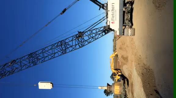
61 Vibro Compaction & Dynamic Compaction
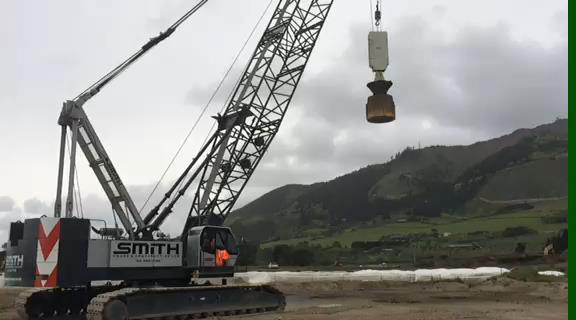
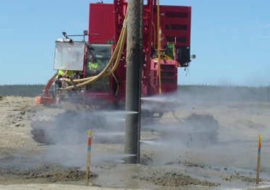
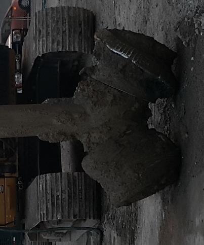
62 Dynamic Compaction in Action

 Paetawa")

 (D60/D10) =")
63 Vibro Compaction Vibro Compaction Trials did not work paction Trials une Sands used in Soil Mixing & Vibrocompaction Trials Sand failed to migrate down towards the probe tip Paetawa Sand Fill (VC) Paetawa Sand Fill (VC) 1 mm 1 mm m m m Dry = 1.30 t/cu.m Passing 0.15mm = 65% Compacted Bulk = 1.84 t/cu.m Passing 0.063mm (Silt) = Dry 1% = 1.51 t/cu.m Uniformity Water Coefficient Content (%) (D60/D10) = 21.8 = 1.49 Organic Content (%) = NJW NJW

64 Dynamic Compaction Treatment depth varied between 5-8m Average Energy applied was between t-m/m2 Used at 6 different bridge sites
65 Design Process 1. Identify design parameters 2. Check SI for suitability of treatment method 3. Establish treatment / pass layout 4. Determine average energy input required 5. Establish weight, drop height, drops per point & passes 6. Calculate any predicted surface settlement (if required) 7. Evaluate environmental effects 8. Complete trial compaction to confirm predictions 9. Undertake DC 10. Test


66 3. Establish Treatment / Pass layout Grid pattern used is typically a function of the treatment depth. Crudely speaking the distance between drop points = depth of treatment 6m x 6m initial point layout 6m Depth 3m x 3m final point layout
67 4. Determine Average Energy Required Type of Deposit Pervious Coarsegrained (sand) Semi-pervious, (silts) Impervious above the water table (silt or clay) Landfill D50 (mm) PI Permeability range (m/s) Total Energy Input (t-m/m3) >0.1 0 > 1 x 10⁻⁴ < 30 t-m/m to 0.1 < 8 1 x 10⁻⁴ to 10-8 < 40 t-m/m3 <0.01 > 8 < 1 x 10⁻⁸ < 40 t-m/m3 < 50 t-m/m3
68 4. Determine Average Energy Required Pass Grid Weight No. of Drops Drop height Treatment Depth Total Energy (t-m/m2) 1 6m x 6m 13t 14 12m 6m m x 6m 13t 14 12m 6m Total Energy (t-m/m3) 3 6m x 6m 13t 14 8m 6m m x 6m 13t 14 8m 6m 40 7 Total Energy input

69 9. Undertake DC
70 10. Results 20t-m/m3 34t-m/m3

71 10. Results - Peat
72 Results High Energy vs Low Energy High Energy 10m depth Low energy Stiff upper layer MPa 3m
73 Environmental Effects

74 Environmental Effects British Standard BS :2009 defines the following guidance values for resultant peak particle velocities (PPV) at the foundation level for buildings in good condition: Structural damage: 50mm/s Minor architectural damage: 15mm/s Felt by occupants: 2.5mm/s Contingency plan: Review drop height & drop weight Re-locate occupants if necessary Review and amend GI method
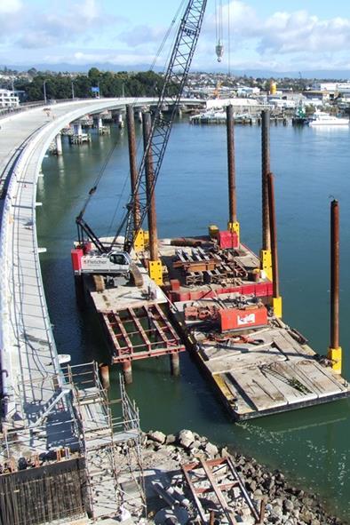
75 Innovations and R&D Currently working on developments in the following areas: Dynamic Replacement in peat deposits With and without the use of PVD drains Dynamic Replacement Mixing method in peat deposits Driving columns of sand into peat using low energy blows Using high energy blows to then disperse sand column into the surrounding peat Underwater ground improvement for land reclamation DR columns, crane and barge work. Drilled displacement columns in granular soil conditions DDP columns for liquefaction mitigation
76 Discussion Thank you for your attention!
Application of Vibro Techniques for Infrastructure Projects in India
 Application of Vibro Techniques for Infrastructure Projects in India Rainer Wegner Contract Manager, Keller Grundbau GmbH, Germany Dr. V.R. Raju Director, Keller Ground Engineering India Pvt Ltd, India
Construction and Geotechnical Issues
 AECOM port project images here Original must be proportionate to 25.4cm x 8cm Image here Original must be square Image here Original must be square Image here Original must be square Construction and Geotechnical
Ground Modification Applications for Bio-Fuel Plants Raymond J. Franz, P.E. Roselle, IL
 Geotechnics and Supplying Future Energy Needs: Ground Modification Applications for Bio-Fuel Plants Raymond J. Franz, P.E. Roselle, IL Bio-Fuel Facilities Current and future energy needs demand consideration
Ground Improvement Specialists
 is a design-build specialty geotechnical contractor offering expertise on ground improvement for sites with poor soil. We combine value engineering and innovative techniques to deliver practical, sustainable
Evaluation the Effectiveness of Rapid Impact Compaction (RIC) as a Ground Improvement Technique
 as a Ground Improvement Technique") Evaluation the Effectiveness of Rapid Impact Compaction (RIC) as a Ground Improvement Technique Bashar Tarawneh, Ph.D, P.E Assistant Professor Civil Engineering Department The University of Jordan Amman,
Evaluation the Effectiveness of Rapid Impact Compaction (RIC) as a Ground Improvement Technique Bashar Tarawneh, Ph.D, P.E Assistant Professor Civil Engineering Department The University of Jordan Amman,
A POORLY GRADED SAND COMPACTION CASE STUDY
 Proceedings of Softsoils 2014, October, 21-23 rd 2014 A POORLY GRADED SAND COMPACTION CASE STUDY Liu Yu 1, Marcello Djunaidy 2 ABSTRACT: One 350 hectare artificial island using hydraulic dredging sand
Expert Solution in BUILD ON US GEOTECHNICAL AND CIVIL ENGINEERING CONTRACTORS
 Expert Solution in VIBROFLOTTATION STONE COLUMNS INCLUSIONS SOIL MIXING SOLID INJECTION DYNAMIC COMPACTION DYNAMIC REPLACEMENT VERTICAL DRAINS P L A T F O R M S A N D S O I L I M P R O V E M E N T GEOTECHNICAL
A Case Study: Foundation Design in Liquefiable Site
 RESEARCH ARTICLE OPEN ACCESS A Case Study: Foundation Design in Liquefiable Site Tahar Ayadat* *(Department of Civil Engineering, College of Engineering, PMU University, P.O. Box 1664, Al-Khobar, 31952,
Compressibility of Soil. Chapter 11
 Compressibility of Soil Chapter 11 TOPICS INTRODUCTION ELASTIC SETTLEMENT Stress distribution in soil masses CONSOLIDATION SETTLEMENT Fundamentals of consolidation Calculation of 1-D Consolidation Settlement
BRE Seminar Ground treatment - Getting the best from difficult sites A Reality Check What Does the Designer Need to Know?
 BRE Seminar Ground treatment - Getting the best from difficult sites A Reality Check What Does the Designer Need to Know? Chris Raison BEng MSc CEng MICE MASCE Raison Foster Associates Introduction A few
Review and Feasibility Assessment of Offshore Ground Improvement Methods
 Review and Feasibility Assessment of Renmin Zhang, Postgraduate Student AOG 2017 Background Final semester study project (6 months) Course completion fulfillment Master of Subsea Engineering (MC-SBSENG)
Comparison of Liquefaction Mitigation Options: A Christchurch Case Study
 Comparison of Liquefaction Mitigation Options: A Christchurch Case Study 2013 NZSEE Conference D.P. Mahoney & J. Kupec Aurecon New Zealand Limited. ABSTRACT: Following the 4 September 2010 M w 7.1 Darfield
Soil Improvement Using Vibro-Replacement
 d GEOTECHNICAL ENGINEERING 1 Soil Improvement Using Vibro-Replacement Dustin S. Spears Abstract A major role of geotechnical engineering involves finding ways to stabilize soils under various conditions.
Ground improvement support using Confined aggregate piers in soft soil. Brian Metcalfe, P.E. Director of Engineering Geopier Foundation Company
 Ground improvement support using Confined aggregate piers in soft soil Brian Metcalfe, P.E. Director of Engineering Geopier Foundation Company OUTLINE Ground improvement historical perspective Confined
Ground Improvement. Martin G. Taube, P.E., P.G. February 4, 2003
 ODOT Geotechnical Information Exchange Seminar Ground Improvement Martin G. Taube, P.E., P.G. February 4, 2003 Nicholson Construction Company 12 McClane Street Cuddy, PA 15031 ph. (412) 221-4500 fax (412)
Study of Various Techniques for Improving Weak and Compressible Clay Soil under a High Earth Embankment
 MATEC Web of Conferences 11, 03006 ( 2014) DOI: 10.1051/ matecconf/ 20141103006 C Owned by the authors, published by EDP Sciences, 2014 Study of Various Techniques for Improving Weak and Compressible Clay
Compaction and Jet Grouting
 Compaction and Jet Grouting Alan Ringen, PE Senior Vice President Breakthroughs in Tunneling Short Course August 16, 2017 Grouting Principles Geotechnical Grouting: The injection of pumpable fluid materials
APPENDIX F GEOTECHNICAL INVESTIGATION UPDATE CITY OF SANTA CRUZ D RAFT EIR L A B AHIA H OTEL JANUARY 2014
 GEOTECHNICAL INVESTIGATION UPDATE. CITY OF SANTA CRUZ D RAFT EIR L A B AHIA H OTEL JANUARY 2014 October 5, 2013 Project No. SCR-0720 SANTA CRUZ SEASIDE COMPANY Craig French 911 Center Street, Suite B Santa
Advantages / Disadvantages of Piling Methods. Continuous Flight Auger (CFA)
") Advantages / Disadvantages of Piling Methods In this Piling Advice Note we will explore the advantages and disadvantages of differing types of piling methods. Continuous Flight Auger (CFA) The pile is
Advantages / Disadvantages of Piling Methods In this Piling Advice Note we will explore the advantages and disadvantages of differing types of piling methods. Continuous Flight Auger (CFA) The pile is
Brochure 66-01E. Compaction Grouting
 Brochure 66-01E Compaction Grouting Contents The method on the market... 3 Process description... 4 Soil improvement... 6 Foundation rehabilitation... 8 Cavity grouting... 10 2 Development The compaction
Ground Improvement. A Discussion on Dynamic Compaction. Chris Woods, P.E., D.GE., LEED AP BD+C Vice-President
 Ground Improvement A Discussion on Dynamic Compaction Chris Woods, P.E., D.GE., LEED AP BD+C Vice-President Presentation Outline Provide a basic understanding of the principles involved in the design and
Estimation of in-situ water content, void ratio, dry unit weight and porosity using CPT for saturated sands
 Barounis, N. & Philpot, J. (217) Estimation of in-situ water content, void ratio, dry unit weight and porosity using CPT for saturated sands Proc. 2 th NZGS Geotechnical Symposium. Eds. GJ Alexander &
GROUND ENGINEERING. Vibro Ground Improvement
 Vibro Ground Improvement Deep vibro techniques present flexible solutions for soil improvement. They are mainly used under foundations of structures that are to be constructed on soils of low bearing capacity
Comparison of the results of load test done on stone columns and rammed aggregate piers using numerical modeling
 Comparison of the results of load test done on stone columns and rammed aggregate piers using numerical modeling Ece Kurt Civil Eng., M.Sc.& Geoph. Eng., Istanbul, Turkey Berrak Teymur Asst. Prof. Dr.,
Code No: RR Set No. 1
 Code No: RR320101 Set No. 1 III B.Tech Supplimentary Examinations, Aug/Sep 2008 GEOTECHNICAL ENGINEERING (Civil Engineering) Time: 3 hours Max Marks: 80 Answer any FIVE Questions All Questions carry equal
GROUND IMPROVEMENT SITE INVESTIGATON
 GROUND IMPROVEMENT SITE INVESTIGTON November 2009 Lankelma ltd old Harbour arn old Harbour Lane Iden, East Sussex TN31 7UT U.K. T: +44 (0)1797 280050 E: info@lankelma.com www.lankelma.com Gardline Lankelma
GEOTECHNICAL ENGINEERING CHALLENGES ON SOFT GROUND. For Myanmar Engineering Society 2012 CONTENTS
 GEOTECHNICAL ENGINEERING CHALLENGES ON SOFT GROUND For Myanmar Engineering Society 2012 G&P Professional Sdn Bhd (www.gnpgroup.com.my) By Engr. Dr. Gue See Sew (P.Eng) Engr. Dr. Wong Shiao Yun (G.Eng)
Earthwork and Ground Technology. Site Improvement
 Earthwork and Ground Technology Site Improvement Slides adapted and upgraded from original presentation slide by College of Engineering, University of Washington. Methods of site improvement Removal and
RIGID INCLUSIONS. Rigid Inclusions offer an economical approach for building on sites underlain by soft soil.
 H A Y W A R D B A K E R I N C. RIGID INCLUSIONS Rigid Inclusions offer an economical approach for building on sites underlain by soft soil. Above: HBI installed Rigid Inclusions on a congested downtown
Steel screw settlement reduction piles for a raft foundation on soft soil
 Proc. 18 th NZGS Geotechnical Symposium on Soil-Structure Interaction. Ed. CY Chin, Auckland Alexei Murashev Opus International Consultants Limited, Wellington, New Zealand. Keywords: piled raft, settlement
Ground Improvement Techniques
 GRD Journals Global Research and Development Journal for Engineering Recent Advances in Civil Engineering for Global Sustainability March 2016 e-issn: 2455-5703 Ground Improvement Techniques 1 Nimisha
INSTITUTE OF AERONAUTICAL ENGINEERING (Autonomous) Dundigal, Hyderabad CIVIL ENGINEERING
 Dundigal, Hyderabad CIVIL ENGINEERING") INSTITUTE OF AERONAUTICAL ENGINEERING (Autonomous) Dundigal, Hyderabad -00 03 CIVIL ENGINEERING QUESTION BANK Course Name : GROUND IMPROVEMENT TECHNIQUES Course Code : A012 Class : III B. Tech IISemester
INSTITUTE OF AERONAUTICAL ENGINEERING (Autonomous) Dundigal, Hyderabad -00 03 CIVIL ENGINEERING QUESTION BANK Course Name : GROUND IMPROVEMENT TECHNIQUES Course Code : A012 Class : III B. Tech IISemester
A STUDY ON GROUND IMPROVEMENT USING STONE COLUMN TECHNIQUE
 A STUDY ON GROUND IMPROVEMENT USING STONE COLUMN TECHNIQUE Karun Mani 1, Nigee.K 2 U.G Student, Dept, of Civil Engineering, M.A.College of Engineering, Ernakulam, Kerala, India 1 P.G Student, Applied Mechanics
GEOSYNTHETICS ENGINEERING: IN THEORY AND PRACTICE
 GEOSYNTHETICS ENGINEERING: IN THEORY AND PRACTICE Prof. J. N. Mandal Department of civil engineering, IIT Bombay, Powai, Mumbai 400076, India. Tel.022-25767328 email: cejnm@civil.iitb.ac.in Module - 9
In-ground cellular structure as a foundation system
 In-ground cellular structure as a foundation system E. Stocks, A. Riman & S. Palmer Tonkin & Taylor Ltd, Wellington. A. Thornton & N. Vance Dunning Thornton Consultants Ltd, Wellington 2017 NZSEE Conference
Ground Improvement for Mitigation of Failure Risks to Existing Embankment Dams
 Ground Improvement for Mitigation of Failure Risks to Existing Embankment Dams by James K. Mitchell, Sc.D., P.E., Dist. M.ASCE University of Alberta, Edmonton, Alberta October 6, 2010 1 SCOPE OF THE LECTURE
GROUND IMPROVEMENT USING DYNAMIC REPLACEMENT FOR NCIG CET3 COAL STOCKYARD
 FOR NCIG CET3 COAL STOCKYARD Charles CH Chua 1, Ming Lai 2, Graeme Hoffmann 2 and Brett Hawkins 1 1 Connell Hatch, Australia, 2 Keller Ground Engineering Pty Ltd ABSTRACT This paper presents an overview
SECTION XXXXX AGGREGATE PIERS PART 1 - GENERAL
 SECTION XXXXX AGGREGATE PIERS PART 1 - GENERAL 1.1 RELATED DOCUMENTS: Drawings and general provisions of the Contract, including General and Supplementary Conditions and other Division 00 and Division
Innovative Soil Reinforcement Method to Control Static and Seismic Settlements
 Innovative Soil Reinforcement Method to Control Static and Seismic Settlements Mike Majchrzak 1 GE, MASCE, Tom Farrell 2 GE, MASCE, Brian Metcalfe 3, PE MASCE 1 Geotechnical Principal Engineer, Kleinfelder,
Brochure E. Deep Vibro Techniques
 Brochure 1-2 E Deep Vibro Techniques Deep vibro techniques present flexible solutions for soil improvement. They are mainly used under foundations of structures that are to be constructed on soils of low
ASCE Geo-institute (G-I) Soil Improvement Committee
 Soil Improvement Committee") ASCE Geo-institute (G-I) Soil Improvement Committee Lectures on Offer from the Soil Improvement Committee (2018-2019) Please Contact: Jose Clemente, jlclemen@bechtel.com Introduction to Lightweight Fill
ASCE Geo-institute (G-I) Soil Improvement Committee Lectures on Offer from the Soil Improvement Committee (2018-2019) Please Contact: Jose Clemente, jlclemen@bechtel.com Introduction to Lightweight Fill
MIDAS ELITE SERIES SOIL STRUCTURE INTERACTION ANALYSIS OF SKYSCRAPER IN BRAZIL RICARDO BORN
 MIDAS ELITE SERIES SOIL STRUCTURE INTERACTION ANALYSIS OF SKYSCRAPER IN BRAZIL RICARDO BORN Civil Engineer, Master in Geotechnical Engineering BS Consulting Brazil Contents 01 Intro 02 Building details
Experience of a Large Scale Unintentionally Long Surcharge on Organic Soils
 Experience of a Large Scale Unintentionally Long Surcharge on Organic Soils Ying Liu, Ph.D., P.E., Senior Engineer, Group Delta Consultants, Inc., 37 Amapola Ave., Suite 212, Torrance, CA. Email: yingl@groupdelta.com
Ground Improvement Piling Piled Retaining Walls Enlarged Head Piles Innovations.
 Ground Improvement Piling Piled Retaining Walls Enlarged Head Piles Innovations www.keller-foundations.co.uk 4 Ground Improvement Solutions Introduction Ground Improvement Solutions Keller Ground Engineering
Table 1. Typical Soil Parameters Description Bulk Density, kn/m 3 Liquid Limit, % Plastic limit, % Natural Moisture Content, % Cohesion, kn/m 2 Compre
 CASE STUDY CONSTRUCTION OF HIGH ROAD EMBANKMENT OVER THICK SOFT SILTY CLAY- A CASE STUDY Radhakrishnan R, Geo-Enviro Engineers P Ltd, Chennai, Tamil Nadu, India, 044-24483522, geoenviro2012@gmail.com.
Introduction to Foundations on Fill and Backfilling
 Introduction to Foundations on Fill and Backfilling Course No: G01-003 Credit: 1 PDH J. Paul Guyer, P.E., R.A., Fellow ASCE, Fellow AEI Continuing Education and Development, Inc. 9 Greyridge Farm Court
A CASE HISTORY ON DESIGN, CONSTRUCTION, AND PERFORMANCE OF STONE COLUMN GROUND IMPROVEMENT BENEATH AN MSE EMBANKMENT
 A CASE HISTORY ON DESIGN, CONSTRUCTION, AND PERFORMANCE OF STONE COLUMN GROUND IMPROVEMENT BENEATH AN MSE EMBANKMENT Karen Dawson, P.E. and Seungcheol Shin, Ph.D., P.E., CH2M HILL, Bellevue, WA, USA Suthan
CASE STUDY ON DIFFERENT GROUND IMPROVEMENT TECHNIQUES FOR A PROPOSED BUILDING ABSTRACT
 CASE STUDY ON DIFFERENT GROUND IMPROVEMENT TECHNIQUES FOR A PROPOSED BUILDING PRIYANKA KORAGANJI (Asst Professor, Civil engineering Department, V.R. Siddhartha engineering College, Kanuru, India, priyakoraganji@gmail.com)
Topic #4 Soil Compaction
 Topic #4 Soil Compaction What is Compaction? A simple ground improvement technique, where the soil is densified through external compactive effort. Compactive Effort + Water = 2 Compaction and Phase Diagram
Chapter 19 GROUND IMPROVEMENT
 Chapter 19 GROUND IMPROVEMENT Final SCDOT GEOTECHNICAL DESIGN MANUAL June 2010 Table of Contents Section Page 19.1 Introduction...19-1 19.2 Prefabricated Vertical Drains...19-3 19.2.1 Design Concepts...19-4
FITZGERALD AVE RETAINING WALL EARTHQUAKE DAMAGE
 FITZGERALD AVE RETAINING WALL EARTHQUAKE DAMAGE Presentation to REAAA NZ Chapter 19 Aug 2013 Greg Saul Principal Geotechnical Engineer Opus International Consultants Ltd Site Locality Plan Site Fitzgerald
RIGID INCLUSIONS FOR SOIL IMPROVEMENT IN A 76 BUILDING COMPLEX
 RIGID INCLUSIONS FOR SOIL IMPROVEMENT IN A 76 BUILDING COMPLEX Walter I. Paniagua, PILOTEC, Mexico City Enrique Ibarra, ingeum, Mexico City Jose A. Valle, PILOTEC, Mexico City Abstract: A 76 building complex
COLLOQUIUM ON GROUND IMPROVEMENT. ZÜRICH 24 October 2013
 ETH ZÜRICH COLLOQUIUM ON GROUND IMPROVEMENT ZÜRICH 24 October 2013 TC-211 ISSMGE Concept & Geotechnical parameters for the Design and Control of major ground improvement works around the world Serge VARAKSIN
t ghi yr Cop
 In many situations, soil itself is used as a construction material Highway embankments Railway embankments Earth dams Highway / Airfield pavements Backfilled trenches Landfills When soil is used as foundation
NPTEL Course GROUND IMPROVEMENT
 Lecture 8 NPTEL Course GROUND IMPROVEMENT Prof. G L Sivakumar Babu Department of Civil Engineering Indian Institute of Science Bangalore 560012 Email: gls@civil.iisc.ernet.in Vibro-compaction methods Compaction
Construction of Highway Embankment Using Controlled Modulus Columns
 Construction of Highway Embankment Using Controlled Modulus Columns Samuel Briet, Branch Manager Central Canada, Geopac, Jean Francois Morel, Vice President of Engineering, Geopac Paper prepared for presentation
Effective improvement depth for ground treated with rapid impact compaction
 Scientific Research and Essays Vol. 5(18), pp. 2686-2693, 18 September, 2010 Available online at http://www.academicjournals.org/sre ISSN 1992-2248 2010 Academic Journals Full Length Research Paper Effective
Liquefaction Remediation by Compaction Grouting
 Liquefaction Remediation by Compaction Grouting R.P. Orense Dept of Civil & Environmental Engineering, University of Auckland 2008 NZSEE Conference ABSTRACT: After the 1995 Kobe Earthquake, the use of
Ground Improvement Prof. G.L. Shivakumar Babu Department of Civil Engineering Indian Institute of Science, Bangalore
 Ground Improvement Prof. G.L. Shivakumar Babu Department of Civil Engineering Indian Institute of Science, Bangalore Module No. # 03 Lecture No. # 09 Case Studies in Stone Columns As I just mentioned in
Keywords: Jet Grouting, Deep Soil Mixing, Controlled Modulus Columns ABSTRACT
 Recent Application of Ground Improvement Technology in Australia and the Pacific Region (2/2) Charles Spaulding Austress Menard, Macquarie Park, NSW, Australia Ernst Friedlaender Keller Ground Engineering,
Long-Term Settlement Performance Monitoring, I-15 Reconstruction Project, Salt Lake City, UT. Steven Bartlett, University of Utah
 1 Long-Term Settlement Performance Monitoring, I-15 Reconstruction Project, Salt Lake City, UT Steven Bartlett, University of Utah Roadway Widening (I-15 Project) Salt Lake City Utah, USA 2002 Host of
ADVANCED GEOSOLUTIONS INC AGI FOUNDATION CONTRACTORS, ULC (Canada Subsidiary) The premier design-build ground improvement contractor TM
 The premier design-build ground improvement contractor TM") ADVANCED GEOSOLUTIONS INC AGI FOUNDATION CONTRACTORS, ULC (Canada Subsidiary) The premier design-build ground improvement contractor TM 1 AGI / WITH YOU FROM CONCEPT-TO-COMPLETION AGI is the premier design-build
ADVANCED GEOSOLUTIONS INC AGI FOUNDATION CONTRACTORS, ULC (Canada Subsidiary) The premier design-build ground improvement contractor TM 1 AGI / WITH YOU FROM CONCEPT-TO-COMPLETION AGI is the premier design-build
Behavior of Reinforced Embankment on Soft Ground with and without Jet Grouted Soil-Cement Piles
 Behavior of Reinforced Embankment on Soft Ground with and without Jet Grouted Soil-Cement Piles by 1 Dennes T. Bergado and 2 Glen A. Lorenzo 1 Professor and 2 Doctoral Candidate, respectively Geotechnical
Misan University - College of Engineering Civil Engineering Department
 CHAPTER 2 Soil and Excavations Soil investigation including two phases: surface investigation and subsurface investigation Surface investigation involves making a preliminary judgment about the site s
Northport Berth 3 design and construction monitoring
 Proc. 18 th NZGS Geotechnical Symposium on Soil-Structure Interaction. Ed. CY Chin, Auckland Lucy Coe, Nicola Ridgley, Do Van Toan Beca Infrastructure Limited, Auckland, NZ Keywords: retaining wall, deflections,
Typical set up for Plate Load test assembly
 Major disadvantages of field tests are Laborious Time consuming Heavy equipment to be carried to field Short duration behavior Plate Load Test Sand Bags Platform for loading Dial Gauge Testing Plate Foundation
twenty four foundations and retaining walls Foundation Structural vs. Foundation Design Structural vs. Foundation Design
 ALIED ARCHITECTURAL STRUCTURES: STRUCTURAL ANALYSIS AND SYSTEMS DR. ANNE NICHOLS SRING 2018 lecture twenty four Foundation the engineered interface between the earth and the structure it supports that
Performance of Mechanically Stabilized Earth walls over compressible soils
 Performance of Mechanically Stabilized Earth walls over compressible soils R.A. Bloomfield, A.F. Soliman and A. Abraham The Reinforced Earth Company, Vienna, Virginia, USA ABSTRACT: Two projects have recently
STATIC ALTERNATING CYCLIC HORIZONTAL LOAD TESTS ON DRIVEN
 STATIC ALTERNATING CYCLIC HORIZONTAL LOAD TESTS ON DRIVEN STEEL PIPE PILES OF FOUNDATIONS FOR HIGHWAY BRIDGES Kouichi TOMISAWA, Civil Engineering Research Institute of Hokkaido, Japan Satoshi NISHIMOTO,
Construction Technology B (CON4313)
") 3 - Basement 1 Quick Revision 1.1 Problems arising from basement construction a. Excavation method. b. Surface and ground water control c. Lateral stability of basement excavation. d. Stability of adjoining
3 - Basement 1 Quick Revision 1.1 Problems arising from basement construction a. Excavation method. b. Surface and ground water control c. Lateral stability of basement excavation. d. Stability of adjoining
THE ADVANTAGES OF THE USE OF GPS BASED LOGGING SYSTEMS FOR VERTICAL DRAIN INSTALLATION PROJECTS
 International Conference on Soft Ground Engineering (ICSGE2015) 3-4 December 2015, Singapore THE ADVANTAGES OF THE USE OF GPS BASED LOGGING SYSTEMS FOR VERTICAL DRAIN INSTALLATION PROJECTS JEROEN DIJKSTRA
SECTION / ENGINEERED AGGREGATE PIERS (SOIL REINFORCEMENT AND FOUNDATION SYSTEM)
") PART 1 GENERAL 1.01 WORK INCLUDED SECTION 02360 / 31 34 30.13 ENGINEERED AGGREGATE PIERS (SOIL REINFORCEMENT AND FOUNDATION SYSTEM) A. Provide all equipment, material, labor and supervision to design and
PART 1 GENERAL 1.01 WORK INCLUDED SECTION 02360 / 31 34 30.13 ENGINEERED AGGREGATE PIERS (SOIL REINFORCEMENT AND FOUNDATION SYSTEM) A. Provide all equipment, material, labor and supervision to design and
LOAD CAPACITY OF AUGER DISPLACEMENT PILES
 International Conference on Ground Improvement and Ground Control (ICGI 2012), 30 Oct. 2 Nov. 2012, University of Wollongong, Australia B. Indraratna, C. Rujikiatkamjorn and J S Vinod (editors) LOAD CAPACITY
Islamic University of Gaza Faculty of Engineering Civil Engineering Department Soil Mechanics Lab ECIV 3151 Final Exam 2016/2017
 Islamic University of Gaza Faculty of Engineering Civil Engineering Department Soil Mechanics Lab ECIV 3151 Final Exam 2016/2017 Instructors: Dr. Jehad T. Hamad Engr. Yasser M. Almadhoun Examination Date:
Inclusion Effect on Heterogeneity of Excess Pore Water Pressure Distribution in Composite Clay
 Inclusion Effect on Heterogeneity of Excess Pore Water Pressure Distribution in Composite Clay J. Jalili Payame Noor University, Iran M. K. Jafari & A. Shafiee International Institute of Earthquake Engineering
ASCE Geotechnical Division Specialty Conference Grouting, Soil Improvement and Geosynthetics New Orleans, Louisiana. February 25-28, 1992
 ASCE Geotechnical Division Specialty Conference Grouting, Soil Improvement and Geosynthetics New Orleans, Louisiana February 25-28, 1992 Shallow Soil Mixing A Case History David Broomhead 1, P. Eng., and
DEPTH EFFECTS AND VIBRATIONS ASSOCIATED WITH DYNAMIC COMPACTION CASE STUDY
 DEPTH EFFECTS AND VIBRATIONS ASSOCIATED WITH DYNAMIC COMPACTION CASE STUDY Derek Avalle 1 and Jaime Tabucanon 2 1 Keller Ground Engineering, PO Box 7974, Baulkham Hills NSW 1755, Australia. E-mail: davalle@kellerge.com.au
204 - EXCAVATION AND BACKFILL FOR STRUCTURES SECTION 204 EXCAVATION AND BACKFILL FOR STRUCTURES. Granular Backfill (Wingwalls) (Set Price)
 (Set Price)") SECTION 204 EXCAVATION AND BACKFILL FOR STRUCTURES 204.1 DESCRIPTION Excavate for the structures as shown in the Contract Documents. Unless specified otherwise, backfill the completed structures to the
SECTION 204 EXCAVATION AND BACKFILL FOR STRUCTURES 204.1 DESCRIPTION Excavate for the structures as shown in the Contract Documents. Unless specified otherwise, backfill the completed structures to the
Earth Mechanics, Inc. Geotechnical & Earthquake Engineering
 DATE: August 31, 2000 Earth Mechanics, Inc. Geotechnical & Earthquake Engineering TECHNICAL MEMORANDUM EMI PROJECT NO: 99-136 PREPARED FOR: COPIES: PREPARED BY: Tayfun Saglam / Parsons Brinckerhoff Juan
NPTEL Course on Ground Improvement
 NPTEL Course on Ground Improvement Prof. G. L. Sivakumar Babu (Questions) Module I - Introduction to Ground Improvement L1: Need for Ground Improvement 1. What are different types of engineering problems
SECTION SOILS REPORT
 SECTION 02300 SOILS REPORT 1. GENERAL: 1.1 All work included under this heading shall be subject to the General Conditions of the entire operation. This Contractor is required to refer especially thereto.
SOIL IMPROVEMENT TO MITIGATE SETTLEMENTS. H. R. AI-Alusi,' Member, ASCE
 Reprinted from Vertical and Horizontal Deformations of Foundations and Embankments Proceedings of Settlement '94 Sponsored by the Geotechnical Engineering Div.lASCE Held June 16-18, 1994, College Station,
An Introduction to Keller in the UK COLCRETE EURODRILL GETEC PHI GROUP. Piling and Ground Improvement. Grouting, Soil Nails and Anchors
 An Introduction to Keller in the UK Piling and Ground Improvement Grouting, Soil Nails and Anchors Retaining Walls Equipment Manufacture Monitoring and Instrumentation PHI GROUP GETEC COLCRETE EURODRILL
Ground Improvement. Cutter Soil Mixing Multi-Axis Soil Mixing Deep Soil Mixing Jet Grouting Vibro Systems Specialized Geotechnical Grouting
 Ground Improvement Cutter Soil Mixing Multi-Axis Soil Mixing Deep Soil Mixing Jet Grouting Vibro Systems Specialized Geotechnical Grouting www.malcolmdrilling.com Cutter Soil Mixing Multi-Axis Soil Mixing
EFFECT OF THE GRID-SHAPED STABILIZED GROUND IMPROVEMENT TO LIQUEFIABLE GROUND
 EFFECT OF THE GRID-SHAPED STABILIZED GROUND IMPROVEMENT TO LIQUEFIABLE GROUND K SATO 1 And T MATSUDA 2 SUMMARY Effective countermeasures for liquefaction of sandy ground under or adjacent to existing structures
Technical Specification for the use of Lightweight Expanded Clay Aggregate (Optiroc LWA) as a Structural Backfill material
 as a Structural Backfill material") Technical Specification for the use of Lightweight Expanded Clay Aggregate (Optiroc LWA) as a Structural Backfill material Preamble Originally produced by the Transport Research Laboratory as a request
Technical Specification for the use of Lightweight Expanded Clay Aggregate (Optiroc LWA) as a Structural Backfill material Preamble Originally produced by the Transport Research Laboratory as a request
Pile foundations Introduction
 Engineering manual No. 12 Updated: 06/2018 Pile foundations Introduction Program: Pile, Pile CPT, Pile Group The objective of this engineering manual is to explain the practical use of programs for the
Seismic Design & Retrofit of Bridges- Geotechnical Considerations
 Seismic Design & Retrofit of Bridges Part 4: Geotechnical Presented by Dr. Ken Fishman,P.E. McMahon & Mann Consulting Engineers, P.C. 1 MULTIDISCIPLINARY CENTER FOR EARTHQUAKE ENGINEERING RESEARCH MCEER
Soil Compaction. Chapter (6) Instructor : Dr. Jehad Hamad
 Instructor : Dr. Jehad Hamad") Soil Compaction Chapter (6) Instructor : Dr. Jehad Hamad 1 2017-2016 What is Compaction? In most instances in civil engineering and/or construction practice, whenever soils are imported or excavated and
Soil Compaction Chapter (6) Instructor : Dr. Jehad Hamad 1 2017-2016 What is Compaction? In most instances in civil engineering and/or construction practice, whenever soils are imported or excavated and
the ground improvement specialist Design Construct Perform
 the ground improvement specialist Design Construct Perform ABOUT US Menard is a worldwide leader in ground improvement works, providing complete range of ground improvement techniques to meet specific
Soil Mechanics IX. SOIL IMPROVEMENT
 Soil Mechanics IX. SOIL IMPROVEMENT Methods for Soil Improvement Ground Reinforcement Stone Columns Soil Nails Deep Soil Nailing Micropiles (Mini-piles) Jet Grouting Ground Anchors Geosynthetics Fiber
Civil Engineering Construction I (CBE5031)
") Civil Engineering Construction I (CBE5031) Basement 1 1 Quick Revision 1.1 Problems arising from basement construction a) Excavation method. b) Surface and ground water control c) Lateral stability of
Civil Engineering Construction I (CBE5031) Basement 1 1 Quick Revision 1.1 Problems arising from basement construction a) Excavation method. b) Surface and ground water control c) Lateral stability of
Development of the Countermeasure against Roadbed Degradation under Ballastless Tracks for Existing Lines
 Challenge H: For an even safer and more secure railway Development of the Countermeasure against Roadbed Degradation under Ballastless Tracks for Existing Lines Katsumi MURAMOTO, Takahisa NAKAMURA Track
Building Construction
 Building Construction Shallow Foundations Module-III Introduction The foundation can be classified broadly into two types: Shallow foundations Deep foundations Shallow foundations Shallow Foundations When
Chapter 11 Compressibility of Soil
 Page 11 1 Chapter 11 Compressibility of Soil 1. The compression of soil layers as a result of foundation or other loadings is caused by (a) deformation of soil particles. (b) relocation of soil particles.
GEOSYNTHETICS ENGINEERING: IN THEORY AND PRACTICE
 GEOSYNTHETICS ENGINEERING: IN THEORY AND PRACTICE Prof. J. N. Mandal Department of civil engineering, IIT Bombay, Powai, Mumbai 400076, India. Tel.022-25767328 email: cejnm@civil.iitb.ac.in Module - 4
Session Report Pavements and Fills
 Session Report Pavements and Fills Dr Burt Look Papers in Report Session Verification Of An Impact Rolling Compaction Trial Using Various In Situ Testing Methods Suggested QC Criteria for Deep Compaction
VIBRO REPLACEMENT COLUMNS FOR SHIPYARD INFRASTRUCTURE AT PIPAVAV, GUJARAT, INDIA
 VIBRO REPLACEMENT COLUMNS FOR SHIPYARD INFRASTRUCTURE AT PIPAVAV, GUJARAT, INDIA DEEPAK RAJ 1 and C. V. DIKSHITH 2 1 Keller Ground Engineering India Pvt. Ltd., 203, Wellington Business Park 1, Andheri
LIMITED MOBILITY GROUTING -- PRACTICE IN NORTH AMERICA. Michael Byle, D.GE, F.ASCE,
 LIMITED MOBILITY GROUTING -- PRACTICE IN NORTH AMERICA Michael Byle, D.GE, F.ASCE, Overview INTRODUCTION COMPACTION GROUTING LIMITED MOBILITY GROUTING LMG MATERIALS AND TECHNOLOGY EQUIPMENT GROUT INJECTION
BEHAVIOUR OF GEOTEXTILE REINFORCED STONE COLUMNS MANITA DAS, A.K.DEY ABSTRACT
 BEHAVIOUR OF GEOTEXTILE REINFORCED STONE COLUMNS MANITA DAS, A.K.DEY ABSTRACT Stone columns are being used to improve the bearing capacity and reduce the settlement of a weak or soft soil. The improvement