Review Article Analyses of the OSU-MASLWR Experimental Test Facility
|
|
|
- Marilynn Holt
- 6 years ago
- Views:
Transcription
1 Hindawi Publishing Corporation Science and Technology of Nuclear Installations Volume 212, Article ID , 19 pages doi:1.1155/212/ Review Article Analyses of the OSU-MASLWR Experimental Test Facility F. Mascari, 1 G. Vella, 1 B. G. Woods, 2 and F. D Auria 3 1 Dipartimento dell Energia, Università degli Studi di Palermo, Viale delle Scienze, Edificio 6, 9128 Palermo, Italy 2 Department of Nuclear Engineering & Radiation Health Physics, Oregon State University, 116 Radiation Center, Corvallis, OR , USA 3 San Piero a Grado Nuclear Research Group (SPGNRG), Università di Pisa, Italy Correspondence should be addressed to F. Mascari, mfulvio78@yahoo.it Received 3 July 211; Accepted 25 October 211 Academic Editor: Alessandro Del Nevo Copyright 212 F. Mascari et al. This is an open access article distributed under the Creative Commons Attribution License, which permits unrestricted use, distribution, and reproduction in any medium, provided the original work is properly cited. Today, considering the sustainability of the nuclear technology in the energy mix policy of developing and developed countries, the international community starts the development of new advanced reactor designs. In this framework, Oregon State University (OSU) has constructed, a system level test facility to examine natural circulation phenomena of importance to multi-application small light water reactor (MASLWR) design, a small modular pressurized water reactor (PWR), relying on natural circulation during both steady-state and transient operation. The target of this paper is to give a review of the main characteristics of the experimental facility, to analyse the main phenomena characterizing the tests already performed, the potential transients that could be investigated in the facility, and to describe the current IAEA International Collaborative Standard Problem that is being hosted at OSU and the experimental data will be collected at the OSU-MASLWR test facility. A summary of the best estimate thermal hydraulic system code analyses, already performed, to analyze the codes capability in predicting the phenomena typical of the MASLWR prototype, thermal hydraulically characterized in the OSU-MASLWR facility, is presented as well. 1. Introduction Today, considering the sustainability of the nuclear technology in the energy mix policy of developing and developed countries, the international community, taking into account the operational experience of the nuclear reactors, starts the development of new advanced reactor designs. Some of the new nuclear reactor designs use passive safety systems based on the use of the natural circulation for the cooling of the core during the designed operational condition and for the removing of the residual heat during transient conditions [1 5]. Emergency systems based on natural circulation are considered, for example, in the AP6/1 design, WWER- 1/V-392 and WWER-64/V-47 designs, AC-6 design, SMART design, IRIS design, SWR 1 MWe design, and in the ESBWR design [4 7]. Examples of reactors that rely on natural circulation for the removing of the core power during normal operation are the MASLWR, the ESBWR, the SMART, and the CAREM design [5 7]. The MASLWR integral reactor concept [1, 2, 8 13], developed by Idaho National Engineering and Environmental Laboratory, OSU, and NEXANT Bechtel, Figure 1, is a small modular PWR relying on natural circulation during both steady-state and transient operation, which includes an integrated steam generator (SG) consisting of banks of vertical helical tubes contained within the reactor pressure vessel (RPV). The primary coolant flows outside the SG tubes and the feed-water (FW) is fully vaporized resulting in superheated steam at the SG exit. The MASLWR module has a net output of 35 MWe, and a number of modules could be built in increments, in a field concept, to generate electricity in larger electricity grids [8, 11]. OSU has constructed, under a US Department of Energy grant, a system-level test facility, OSU-MASLWR [1, 2, 8 13], to examine natural circulation phenomena of importance to the MASLWR design. Four tests have been conducted in support of the MASLWR concept design verification. Considering the thermal hydraulic phenomena simulating capability of this facility, the planned work will be not only to specifically investigate the MASLWR concept design further but also to advance the broad understanding of integral natural reactor plants and accompanying passive safety features as well.


2 2 Science and Technology of Nuclear Installations PRZ HL (Middle ADS valves) depressurization valve Steam generator tube bundle Water Steam Core Water (High ADS valves) vent valve Containment Reactor pressure vessel Steam Feedwater Sump recirculation valve Turbine generator Condenser Feedwater pump Gen Figure 1: MASLWR conceptual design layout [1, 2, 8, 11, 13]. After the completion of the first test series, through a grant from the International Atomic Energy Agency (IAEA), the OSU-MASLWR test facility core was reconfigured to eliminate a recurring grounding problem and improve facility reliability [12] in anticipation of conducting an IAEA ICSP on Integral PWR Design Natural Circulation Flow Stability and Thermo-hydraulic Coupling of Primary System and Containment During Accidents [14 16]. This ICSP is being hosted at OSU and the experimental data will be collected at the OSU-MASLWR facility, to provide experimental data on single-/two-phase flow instability phenomena under natural circulation conditions and coupled containment/ reactor vessel behavior in integral type light water reactors. The target of this paper is to give a review of the main characteristics of the experimental facility, to analyse the main phenomena characterizing the tests already performed, the potential transients, of interest for integral reactor types, that could be investigated in the facility, and to describe the current IAEA ICSP. A summary of the best estimate thermal hydraulic system code analyses, already performed, to investigate the codes capability in predicting the phenomena typical of the MASLWR prototype, thermal hydraulically characterized in the OSU-MASLWR facility, is presented as well. 2. MASLWR Design 2.1. MASLWR Overview. The MASLWR [1, 2, 8 13], Figure 1, is a small modular integral PWR relying on natural circulation during both steady-state and transient operations. The use of natural circulation reduces the number of active components simplifying the configuration of nuclear steam supply system. The RPV contains the core, the pressurizer (PRZ), and an integrated SG consisting of banks of vertical helical tubes located in the upper region of the vessel outside of the hot leg (HL) chimney. The MASLWR steady-state operating conditions are reported in Table 1. The RPV is surrounded by a cylindrical containment, partially filled with water. This containment provides pressure suppression and liquid makeup capabilities and is submerged in a pool of water that acts as the ultimate heat sink. Table 1: MASLWR steady-state operating conditions [8 1]. Primary side Reactor thermal power 15 MW Primary pressure 7.6 MPa Primary mass flow rate 597 kg/s Reactor inlet temperature K Reactor outlet temperature K Saturation temperature 565 K Reactor outlet void fraction.% Secondary side Steam pressure 1.5 MPa Steam outlet quality 1 Steam temperature K Saturation temperature K Feedwater temperature 31 K Feedwater flow rate 56.1 kg/s The RPV can be depressurized using the automatic depressurization system (ADS), consisting of six valves discharging into various locations within the containment. In particular two independent vent valves (high ADS valve), two independent depressurization valves (middle ADS valve) and two independent sump recirculation valves are considered in the MASLWR design MASLWR SBLOCA Phenomenology Description. Considering the MASLWR integral arrangement, there are not pressurized primary components outside the RPV; therefore the possibility of large-break loss of coolant accident (LOCA) is eliminated and the small-break LOCA (SBLOCA) initiating events are reduced. Of particular interest is the SBLOCA passive mitigation strategy typical of the MASLWR design. Following, for example, an inadvertent opening of an ADS valve, a primary side blowdown into the pressure suppression containment takes place. The RPV blowdown causes a primary pressure decrease and a consequent containment pressure increase causing a safety injection signal. It


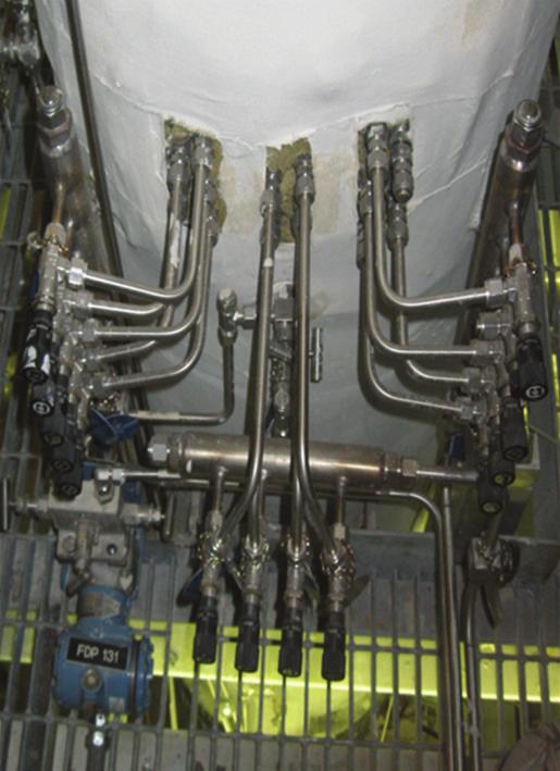
3 Science and Technology of Nuclear Installations 3 Cooling pool vessel High pressure containment Reactor pressure vessel PRZ PRZ heaters Upper plenum SG steam drum SG coils Cold leg HL riser Core flange RPV Cone Chimney Core Lower plenum Figure 3: RPV internal components [1, 2, 11, 13]. Figure 2: OSU-MASLWR experimental facility photo [1, 2, 13]. automatically opens, Figure 1, the high ADS valves, the middle ADS valves, and the sump recirculation valves. As the primary and the containment pressures become equalized, the blowdown is terminated and a natural circulation flow path is established. In fact when the sump recirculation valves are opened, the vapour produced in the core goes in RPV upper part and, through the high ADS valve, goes to the containment where it is condensed. At this point through the sump recirculation lines and the downcomer, the fluid goes to the core again. The pressure suppression containment is submerged in a pool that acts as the ultimate heat sink. This mechanism permits the cooling of the core during the transient [8 11]. 3. Description of the OSU-MASLWR Facility 3.1. OSU-MASLWR Test Facility. In the development process of advanced nuclear reactors, the analysis of single- and twophase fluid natural circulation in complex systems [5, 1, 17 19], under steady-state and transient conditions, is crucial for the understanding of the physical and operational phenomena typical of these advanced designs characterized by the interaction between different parts of the system. The use of experimental facilities is fundamental in order to characterize the thermal hydraulics of these phenomena and to develop an experimental database useful for the validation of the computational tools necessary for the operation, design, and safety analysis of nuclear reactors. Ingeneralitisexpensivetodesignatestfacilitytodevelop experimental data useful for the analyses of complex system; therefore reduced scaled test facilities are in general used to characterize them. Since the experimental data produced have to be applicable to the full-scale prototype, the geometrical characteristics of the facility and the initial and boundary condition of the selected tests have to be correctly scaled. Since possible scaling distortions are present in the experimental facility design, the similitude of the main thermal hydraulic phenomena of interest has to be assured permitting their accurate experimental simulation [1, 11, 18, 19]. OSU has constructed, under a US Department of Energy grant, a system-level test facility to examine natural circulation phenomena of importance to MASLWR design. The scaling analyses of the OSU-MASLWR experimental facility was performed in order to have an adequate simulation of the single- and two-phase natural circulation, reactor system depressurization during a blowdown and the containment pressure response typical of the MASLWR prototype. The model used for the scaling analyses performed in [9, 1] is partly drawn from the USNRC s Severe Accident Scaling Methodology (SASM) presented in NUREG/CR-589 [19]. The detailed OSU-MASLWR scaling analyses is reported in [9, 1]. As a result of the scaling analyses, the OSU-MASLWR test facility [8 13, 18, 19], shown in Figure 2, isscaledat1:3 length scale, 1 : volume scale, and 1 : 1 time scale, is constructed entirely of stainless steel, and is designed for full pressure and full temperature prototype operation. It includes the primary circuit, consisting of the RPV and ADS lines, the secondary circuit, and the containment structures. In addition to the physical structures that comprise the test facility, there are data acquisition, instrumentation, and control systems. Auxiliary lines and systems are present in the facility OSU-MASLWR RPV Overview. The internal components of the RPV [1, 2, 8 13], Figure 3, are the core, the HL
 18.59 mm 18.59 mm Flow holes on periphery are partially blocked by the core shroud Figure 4: Lower core flow plate layout [12].")


4 4 Science and Technology of Nuclear Installations φ6.35 mm flow holes equally spaced on mm square pitch (76) 9.3 mm 9.3 mm φ17.2 mm heater rod flow hole (56) φ17.2 mm thermocouple rod flow hole (1) mm mm Flow holes on periphery are partially blocked by the core shroud Figure 4: Lower core flow plate layout [12].See Figure 5 for flow blockage detail. Interior auxiliary flow hole is adjacent to four core rod flow holes and has full flow area Interior corner auxiliary flow hole is adjacent to three core rod flow holes and has 3/4 the flow area of an interior auxiliary flow hole Exterior corner auxiliary flow hole is adjacent to one core rod flow holes and has 1/4 the flow area of an interior auxiliary flow hole Edge auxiliary flow hole is adjacent to two core rod flow holes and has 1/2 the flow area of an interior auxiliary flow hole Figure 5: Auxiliary flow hole blockage by core shroud [12]. riser, the upper plenum (UP), the PRZ, the SG primary side, the cold leg (CL) downcomer, and the lower plenum (LP). The core is modelled with 56 cylindrical heater rods. A lower core flow plate is located at the core entrance and is shown in Figure 4. The core is shrouded to ensure all flow enters the core via the bottom and travels the entire heated length and to separate the downcomer region from the core region. The core shroud is shaped to partially block the primary coolant flow through the outermost auxiliary flow holes in order to ensure that each heated rod receives approximately equal axial coolant flow, as shown in Figure 5. The amount of blockage is dependent on the number and location of heated rods adjacent to each auxiliary flow hole. The shaded area, Figure 5, indicates where core shroud blocks flow through auxiliary flow holes. A core grid wire, located at core midelevation, is considered in order to maintain the radial alignment of the core rods, Figure 6. The HL riser, Figure 3, consists of a lower region, an upper region, and a cone transition region. The UP is separated from the heated upper PRZ section by a thick baffle plate having eight holes, spaced uniformly around the baffle plate periphery, which allow free communication of the PRZ to the remainder of the RPV during normal operation and for volume surges into and/or out of the PRZ due to transients. The PRZ is integrated in the RPV and is located in its upper part. In the PRZ are located heater elements, which are modulated
![Science and Technology of Nuclear Installations 5 Figure 6: Photo of core shroud showing lower core flow plate behind the core grid wires [12].](/docs-images/77/75329789/images/5-0.jpg "Elevation (18 ) discharge isolation valve MF-58 position, to ensure that the MFP is not energized unless MF-58 is fully open.")


 is immediately downstream of the SG steam drum.")


5 Science and Technology of Nuclear Installations 5 Figure 6: Photo of core shroud showing lower core flow plate behind the core grid wires [12]. Elevation (18 ) discharge isolation valve MF-58 position, to ensure that the MFP is not energized unless MF-58 is fully open. The single MFW line splits into three supply lines, one for each coil bank of SG tubes. The SG of the facility is a once through heat exchanger and is located within the RPV in the annular space between the HL riser and the inside surface of the RPV. The tube bundle,figure 7, is a helical coil consisting of fourteen tubes. There are three separate parallel coils of stainless steel tubes. The outer and middle coils consist of five tubes each while the inner coil consists of four tubes. Each coil is joined at a common inlet header and each of them exhausts the superheated steam into a common steam drum from where it is subsequently exhausted to atmosphere via the MS system. The FW enters at the bottom of the SG and boils off after travelling a certain length in the SG. This boil-off length is a function of both core power and MFW flow rate. Nominally, the boil-off length is approximately 4% shorter than the actual length of the SG tubes so the steam will leave the SG superheated. The value of the degree of the steam superheat is changed in order to control the facility. The steam received in the SG steam drum goes to the MS line, Figure 8, and that exhausts the SG superheated steam to atmosphere. A pneumatic motor operated globe valve MS- 52 (MS header drain line isolation valve) is immediately downstream of the SG steam drum. Another motor operated globe valve, MS-53 (MS header isolation valve), isolates the MS header from the steam header drain line. In order to have always an open discharge for the SG, the MS-52 and MS-53 are interlocked to prevent them both from being simultaneously commanded shut. Figure 7: Helical coil SG bundle [13, 2]. by the test facility control system to maintain nominal primary system pressure at the desired value. The CL downcomer region is an annular region bounded by the RPV wall on the outside and the HL riser on the inside, and the flow area reduces at the HL riser cone. In the SG primary side section is inserted the SG helical coil bundle, Figure 7. The entire RPV is covered by Thermo-12 hydrous calcium silicate insulation OSU-MASLWR Secondary Side Overview. The secondary circuit [1, 2, 8 13] includes the FW treatment and storage system, the main FW pump (MFP), the main FW (MFW) system supply lines, the SG secondary side internal to the vessel, the main steam (MS) system, and associated FW and steam valves. Potable water, coming from the city water supply, passes through a mechanical filter and a resin bed to remove impurities and flows to the FW storage tank. The MFW system supplies deionized and demineralized water to the SG. The MFP is a positive displacement pump and can be isolated from the downstream main FW system supply lines by pneumatic motor operated globe valve MF-58 (FW supply valve). The MFP controller is interlocked with the MFP 3.4. OSU-MASLWR Containment Structures Overview. The OSU-MASLWR containment structures [1, 2, 8 13], Figure 9, consist of two vessels, a high-pressure containment vessel (HPC) and a cooling pool vessel (CPV), with a heat transfer surface between them to establish the proper heat transfer area. The HPC simulates the containment structure in which the MASLWR RPV sit and the CPV simulates the cavity within which the MASLWR containment structure is located. The HPC consists of a lower cylindrical section, an eccentric cone section, an upper cylindrical section, and a hemispherical upper-end head. The entire HPC is covered by Thermo-12 hydrous calcium silicate insulation. The CPV consists of a right cylindrical tank covered by Thermo-12 hydrous calcium silicate insulation. One disk rupture connects the HPC and the CPV. The heat transfer plate, having the same height of the HPC without the hemispherical head, provides the heat conduction between the HPC and CPV. The heat transfer plate is scaled in order to model the heat transfer area between the MASLWR design high-pressure containment vessel and the cooling pool in which it sits. For scaling reasons, in order to have an adiabatic boundary condition in all the wall of the HPC except through the heat transfer plate wall, where the condensation has to take place, containment heaters have been installed permitting the


6 6 Science and Technology of Nuclear Installations Steam line Exhaust steam header Steam drum The middle ADS lines are horizontally oriented and connect the RPV CL to the HPC. A pneumatic motor-operated globe valve is located in each line. Downstream from each isolation valve is a transition piece with an internal squareedge orifice. These two lines enter the HPC, penetrate it, and then turn downward before terminating below the HPC waterline. A sparger is considered at the end of this line. The high ADS lines are horizontally oriented and connect the RPV PRZ steam space with the HPC. A pneumatic motor operated globe valve is located in each line. Downstream from each isolation valve is a transition piece with an internal square-edge orifice. The two ADS vent lines enter the HPC above the waterline, penetrate it, and then terminate with a sparger. Cooling pool vessel Figure 8: Main steam line photo. High-pressure containment Heat transfer plate 3.6. OSU-MASLWR Data Acquisition and Control Subsystem Overview. The data acquisition and control system [1, 2, 8 13] consist of various field input/output modules, a programmable logic controller module, and a desktop computer. The data acquisition and control subsystem process input signals from system components, generate control signals as determined by the control logic, and apply those control signals to applicable system components. The operator can monitor parameters and alarms in the main control screen, via a graphical user interface as it is shown in Figure 11. Individual system component operation algorithms are considered in the facility. The PRZ heaters, for examples, can be operated manually or in automatic mode. In automatic mode, in order to control the primary pressure, the operator fixes the primary pressure set point and the control system, by using aproportional integral differential methods, and adjusts the heater controller electrical output. The core heaters, for example, can be operated in manual mode, constant power mode, or decay mode. In decay mode the core power follows a user specify curve. 4. OSU-MASLWR Testing Program Figure 9: OSU-MASLWR containment structures photo [1, 2, 11]. heat transfer takes place only between the CPV and HPC containment. These heaters are located in the exterior surface of the HPC, under the insulation, and above the containment water level OSU-MASLWR ADS Lines Overview. The two middle ADS lines, two high ADS lines, and the two ADS sump recirculation lines are modelled separately [1, 2, 8 13]. Figure 1 shows the schematic diagram of the OSU-MASLWR RPV, ADS lines, and containment structures. The ADS sump recirculation lines are horizontally oriented and connect the RPV lower CL to the HPC. A pneumatic motor operated globe valve is located in each line. Downstream from each isolation valve is a transition piece with an internal square-edge orifice. These two lines enter the HPC, penetrate it, and then turn downward before terminating below the HPC waterline. No sparger is considered for these lines. The first tests conducted in the OSU-MASLWR facility [8 13] were in support of the MASLWR concept design verification. Table 2 shows, in chronological order, the type of test already conducted in the facility. During this test program, the MASLWR normal startup, the operation, and its shutdown are thermal hydraulically demonstrated OSU-MASLWR-1 Description. The purpose of the test OSU-MASLWR-1 [1, 8 13], a design basis accident for MASLWR concept design, is to determine the behavior of the RPV and containment pressure following an inadvertent actuation of one middle ADS valve located below the HPC and RPV water level. The test successfully demonstrated the thermal hydraulic behavior of the MASLWR design during the transient sequence following this design basis event. Following the inadvertent middle ADS actuation, the blowdown of the primary system takes place. A subcooled blowdown characterized by a fast RPV depressurization takes place after the start of the transient (SOT). A two-phase blowdown occurs when the differential pressure, at the break

7 Science and Technology of Nuclear Installations 7 CPV HPC PRZ ADS vent valves (high ADS valves) RPV Steam line Heat transfer plate Water level ADS blowdown valves (middle ADS valves) SG FW lines Core ADS sump recirculation valves Figure 1: Schematic diagram of the OSU-MASLWR RPV, ADS lines, and containment structures [2, 2]. Table 2: Summary of the previous OSU-MASLWR testing program [8, 11, 13]. Nameofthetest OSU-MASLWR-l OSU-MASLWR-2 OSU-MASLWR-3A OSU-MASLWR-3B Typeoftest Inadvertent actuation of 1 submerged ADS valve. Natural circulation at core power up to 21 kw. Natural circulation at core power of 21 kw. (Continuation of test 2, establishing the initial conditions for the 3B test.) Inadvertent actuation of 1 high-containment ADS valve ADS line configuration Middle Middle High High Sump Sump ADS 1 ADS2 ADS 1 ADS2 Recirc 1 Recirc 2 (%) (%) (%) (%) (%) (%) Failed Shut N/A N/A N/A N/A N/A N/A Failed Shut Failed Shut N/A N/A N/A N/A N/A 1 Failed Shut location, results in fluid flashing. A choked two-phase flow condition prevails, and a decrease in depressurization rate of the primary system is experimentally observed. When the PRZ pressure reaches saturation, single-phase blowdown occurs, and the depressurization rate increases. The primary and HPC pressure are shown in Figure 12. At 539 s after the SOT, the pressure difference between the RPV and the HPC reaches a value less than.517 MPa, one of the high ADS valve is opened and, with approximately 1 s of delay, the other high ADS valve is opened equalizing the pressure of the primary and HPC system. At 561 s after the SOT, the pressure difference between the RPV and the HPC reaches a value less than.34 MPa, one sump recirculation valve is opened, and, with approximately 1 s of delay, the other sump recirculation valve is opened terminating the blow-down period and starting the refill

8 8 Science and Technology of Nuclear Installations 5 4 Level (m) RPV LVL 1 High ADS line HL top HL flow cone Middle ADS line Sump ADS line Core top Figure 11: Data acquisition and control system main control screen [12]. Figure 13: RPV water level inventory behaviour during the OSU- MASLWR-1 test [8, 11]. 8e e +6 Subcooled blowdown 4 Pressure (Pa) 4e +6 Two-phase blowdown Single-phase blowdown Level (m) 3 2e RPV P 1 HPC P 1 Psat 1 Figure 12: RPV and HPC pressure behaviour during the OSU- MASLWR-1 test (the Psat, saturation pressure, is based on the temperature at the core outlet) [8, 11]. period. The refill period takes place for the higher relative coolant height in the HPC compared to the RPV. Figure 13 shows the RPV level evolution experimentally detected during the test. The RPV level water never fell below the top of the core during the execution of the test 1. Figure 14 shows the HPC level during the test. During the saturated blowdown period, the inlet and the outlet temperature of the core are equal to each other assuming the saturation temperature value. A core reverse flow and a core coolant boiling off at saturation are present in the facility during this period. When the refill takes place, the core flow normal flow direction is restarted and a delta T core is observed depending on the refill rate and core power, Figure HPC LVL 1 Figure 14: HPC level behaviour during the OSU-MASLWR-1 test [21, 22]. When the refill of the reactor takes place, the level of the coolant reaches the location of the flow rate HL measurement point; therefore an increase of the RPV flow rate is detected for this phenomenon, Figure OSU-MASLWR-2 and 3A Description. The test OSU-MASLWR-2 and OSU-MASLWR-3A [1, 8 13] investigated the primary system flow rates and secondary side steam superheat for a variety of core power levels and FW flow rate. Table 3 shows the OSU-MASLWR-2 and OSU- MASLWR-3A test conditions. The OSU-MASLWR-2 stepped power level incrementally up to 165 kw, varying FW flow rate at each power level. Since the 21 kw data in OSU-MASLWR-2 was not used, because of liquid carryover in the SG, the OSU-MASLWR- 3A was an extended 21 kw steady test establishing initial conditions for the following test OSU-MASLWR-3B.
9 Science and Technology of Nuclear Installations 9 Test 2 3A Start time (s) End time (s) Table 3: OSU-MASLWR-2 and OSU-MASLWR-3A test conditions [8, 11, 12]. Core power (kw) T in (K) Primary T out (K) Flow (L/min) Vel (m/s) T in (K) T out (K) Secondary P (MPa) Feedwater (kg/min) Flow rate (m 3 /s) T in core 1 T out core 1 Figure 15: Inlet/outlet core temperature behavior during the OSU- MASLWR-1 test [8]. During these two tests, sevendifferent core powers were used as well as nine different FW flow rates. Figures 17 and 18 show the inlet, outlet core, and top of the HL temperature behaviour for the OSU-MASLWR-2 and OSU-MASLWR- 3A test, respectively. In general the value of the degree of the steam superheat is changed in order to control the facility. Since the slope of the MS superheat curve increases if the value of the core power increases and decreases if the value of the FW flow rate increases, the target of these tests was to acquire primary system flow rate and secondary side steam superheat for different core power and FW flow rate. The difference between the MS saturation temperature and the measured MS temperature is used to estimate the value of the MS superheat. Figures 19 and 2 show the steam superheat data for the test OSU-MASLWR-2 and 3A test, respectively. Figure 21 shows the difference of fluid temperature at the inlet of the core and at the exit of the SG primary side for the OSU- MASLWR-2 test. By analyzing the experimental data, RPV flow rate 1 Figure 16: RPV flow rate behavior during the OSU-MASLWR-1 test [8]. related to the flow temperature after the SG coils primary side section and the core inlet temperature, it is evident that the direct heat exchange, through the internal shell, between the fluid ascending the HL and the fluid descending the CL, is a crucial parameter for the evaluation of the core inlet temperature and, therefore, the core outlet temperature. In fact, the experimental data show that, along the downcomer region, the fluid increases its temperature between the end of the SG primary side section and the core inlet [13] OSU-MASLWR-3B Description. The normal opening sequence used in the MASLWR for the ADS valves is the middle lines first, then the high lines, and finally the sump recirculation lines [8 13]. This sequence minimizes the rise in containment pressure since a large fraction of the energy transferred to the containment is direct into the subcooled containment coolant. However, if the high lines are actuated first, the rise in containment pressure will be larger than
10 1 Science and Technology of Nuclear Installations Superheat (K) T out core 2 T in core 2 T top hot leg 2 Figure 17: Inlet, outlet core, and top of the hot leg temperature behavior during the OSU-MASLWR-2 test [8] Steam superheat 2 Figure 19: Steam superheat behavior during the OSU-MASLWR- 2 test [11] Superheat (K) T out core 3A T in core 3A T top hot leg 3A Figure 18: Inlet, outlet core, and top of the hot leg temperature behavior during the OSU-MASLWR-3A test [8] Steam superheat 3A Figure 2: Steam superheat behavior during the OSU-MASLWR- 3A test [11]. 6 the previous one, and, anyway, the chocked flow in the high containment line will limit the rate at which the containment and RPV pressure equalize. Therefore the purpose of the test OSU-MASLWR-3B is to acquire the pressure transient in the containment and the primary system during the inadvertent actuation of one high containment ADS valve. This test represents a beyond design basis accident scenario for the MASLWR and thermal hydraulically characterizes the RPV/containment coupling and containment vessel condensation behavior during this kind of transient. During the test, core power is zero and there is not preheating of the containment noncondensation surface areas. When the high ADS valves open, the pressure equalization of the primary side and containment starts, but it is limited by the chocked flow condition at the ADS nozzles T difference 2 Figure 21: Difference of fluid temperature at the inlet of the core and at the exit of the SG primary side during the OSU-MASLWR- 2 test [13, 22].
11 Science and Technology of Nuclear Installations 11 8e e Pressure (Pa) 4e +6 Level (m) 3 2e RPV P 3B HPC P 3B Figure 22: RPV and HPC pressure behaviour during the OSU- MASLWR test 3B [8, 11] HPC LVL 3B Figure 24: HPC liquid level behaviour during the OSU-MASLWR- 3B test [8]. 8e Pressure (Pa) 6e +6 4e +6 2e T 2.5 m 3B T 3.2 m 3B T 4.1 m 3B T 5.11 m 3B T 5.6 m 3B T sat 3B Figure 23: Containment condensation plate wall temperatures behavior during the OSU-MASLWR-3B [8, 11]. The upper part of the HPC is filled with the steam, coming from the primary side, where condensing transfers energy to the CPV. The analyses of the experimental data show that the HPC pressure reaches a maximum at bar at 185 s after the SOT. Figure 22 shows the RPV and HPC pressure behaviour. Since the preheating of the containment noncondensation surface is not considered during the transient, an adiabatic boundary condition in all the wall of the HPC except through the heat transfer plate wall is not maintained; therefore a small distortion at the beginning of the transient is present during the test. The thermocouples measuring the water temperature located inside the HPC near the heat transfer plate reach quickly the saturation temperature, Figure 23. Since the HPC liquid level reaches about 3.7 m, when the lower thermocouples are submerged, they drop at the liquid temperature, RPV P RELAP5 Mod3.3 RPV P RELAP5 3D RPV P TRACE V5 RPV P EXP Figure 25: Experimental data versus RELAP5/MOD3.3, RELAP5-3D, and TRACE code calculations for primary system pressure behaviour of the OSU-MASLWR-1 test [23]. Figure 24. The RPV level water never fell down the upper part of the core during the execution of the test 3B. 5. Code Analyses Performed Different computer codes have been developed to characterize two-phase flow systems, from a system and a local point of view [1]. Accurate simulation of transient system behavior of a nuclear power plant or of an experimental test facility is the goal of the best estimate thermal hydraulic system codes. The evaluation of a code s calculation accuracy is accomplished by assessment and validation against appropriate system data developed either from a running system prototype or from a scaled model test facility and characterizes the thermal hydraulic phenomena during both steady-state and transient conditions [1, 2, 13, 21 23, 27, 28].
12 12 Science and Technology of Nuclear Installations Level (m) RPV LVL EXP RPV LVL TRACE Core top Figure 26: Experimental data versus TRACE V5 patch 2 code calculations for primary system level of the OSU-MASLWR-1 test [1] T out core EXP T in core EXP T out core P1 T out core P2 T out P2 core HL T in core P1 T in core P2 T in P2 core HL Figure 27: Experimental data versus TRACE V5 code calculations for fluid temperature at the core outlet/inlet of the OSU-MASLWR- 2 test [1](P1= calculation performed with the TRACE V5 patch 1; P2 = calculation performed with the TRACE V5 patch 2; P2 HL calculation performed with the TRACE V5 patch 2 increasing the heat losses of the TRACE model). In this framework, different analyses have been performed [1, 2, 13, 21 24, 27, 28], in order to analyze the capability of the best estimate thermal hydraulic system codes to predict the phenomena typical of the MASLWR prototype and their implication to its operation, thermal hydraulically characterized in the OSU-MASLWR test facility. All the previous tests have been analyzed by using different best estimate thermal hydraulic system code. In general the OSU- MASLWR test facility nodalizations qualification process is still in progress, considering the facility experimental characterization distributed in the framework of the previously mentioned IAEA ICSP [14 16, 2] T out SG EXP T out SG REF T out SG SEN1 T out SG SEN2 Figure 28: Experimental data versus TRACE V5 patch 1 code calculations for the fluid temperature at the SG coil outlet of the OSU-MASLWR-2 test [13]. (REF = SG coils modelled with three different equivalent oblique group of pipes in order to simulate the three separate parallel coils of tubes; SEN1 = SG coils modelled with three different equivalent vertical group of pipes; SEN2 = SG coils modelled with only one equivalent vertical group of pipes) Code Analyses of the OSU-MASLWR-1 Test. The analysis of the OSU-MASLWR-1 test, performed by using RELAP5/MOD3.3, RELAP5-3D, and TRACE [23], shows that the codes are able to qualitative predict primary/containment coupling phenomena characterizing the test. The subcooled, saturated, and single-phase blowdown is predicted by the codes. The refill of the core, permitting its cooling, is predicted as well. The results of the calculated data show a general overprediction compared with the experimental data. It is thought that this could be due to a combination of selection of vent valve discharge coefficients and condensation models applied to the inside surface of the containment [23]. The pressure behaviour of the RPV predicted by these codes is reported in Figure 25.Different update analyses have been developed by using the TRACE code and reported in [1, 21, 22]. Figure 26 shows the experimental data versus code calculations for primary system level for the OSU-MASLWR- 1 test predicted by the TRACE code [1] Code Analyses of the OSU-MASLWR-2 Test. The analyses of the OSU-MASLWR-2 test, developed by using TRACE [1, 13, 21, 22, 27, 28], show that the TRACE code is able to qualitatively predict natural circulation phenomena and heat exchange from primary to secondary side by helical SG in superheated condition. An overestimation of the inlet/ outlet core temperature, Figure 27, is predicted by the code. One of the reasons could be an underestimation of the helical coil heat transfer coefficient during the different phases of the transient. The subcooled, saturated, and superheated regions of the SG secondary side are predicted by the code resulting in steam superheat at the SG exit, Figure 28. Figure 29, developed by using the symbolic nuclear analysis package
13 Science and Technology of Nuclear Installations Core region CL region HL region UP region SG primary side region thermally coupled with SG coils secondary side Normalized height SG primary side Saturated region Superheated region SG-equivalent inner coil Normalized height Subcooled region Figure 29: TRACE RPV temperature profile and SG primary side and equivalent inner coil temperature diagram for the OSU-MASLWR-2 test (265 s after SOT), developed by using SNAP [1]. 7.9e e +6 Pressure (Pa) 7.7e e e P PRZ EXP P PRZ P1 P PRZ P2 P PRZ P2 HL Figure 3: Experimental data versus TRACE V5 code calculations for the PRZ pressure of the OSU-MASLWR-2 test [1]. (P1 = calculation performedwiththetracev5patch1;p2= calculation performed with the TRACE V5 patch 2; P2 HL calculation performed with the TRACE V5 patch 2 increasing the heat losses of the TRACE model). (SNAP), shows the fluid temperature profile, calculated by TRACE code, along the entire natural circulation loop. A detail of the fluid temperature profile along the inner helical coil cells and the fluid temperature profile along the SG primary side section are shown as well. From this figure, it is possible to identify the subcooled, saturated, and superheat region, of the inner equivalent helical coil. In agreement with the experimental data, the steam will leave the SG superheated. The analyses of the TRACE calculated data show that one of the reasons of the instability of the superheat condition of the fluid at the outlet of the SG, already observed in [27], is the equivalent SG model used to simulate the different group of helical coils. In particular, if the helical coils are modelled
14 14 Science and Technology of Nuclear Installations Figure 31: RELAP5-3D nodalization [24]. Pressure (Pa) 8e +6 6e +6 4e +6 2e P RPV EXP P HPC EXP P RPV RELAP5-3D P HPC RELAP5-3D Figure 32: Experimental data versus RELAP5-3D code calculations for the RPV and HPC pressure behaviour of the OSU-MASLWR- 3B [24]. by only one equivalent vertical tube, a more stable fluid temperature at the outlet of the helical tubes is predicted by the code. The model with three different oblique or vertical tubes needs more investigations, in order to study the possible instability conditions predicted by the code [13]. Previous PRZ pressure discrepancies, Figure 3, predicted by the TRACE V5 patch 1, are now not predicted by the patch 2 that shows, in general, a more stable prediction of PRZ pressure and level [1]. TRACE model heat losses and pressure drop calibration against an experimental characterization is necessary, as it is reported in [1, 13], in order to quantitatively evaluate the capability of these codes to simulate the OSU-MASLWR phenomena and therefore use the calculated data for the code assessment. Figure 27 shows the behavior of inlet/outlet core temperature by increasing the heat losses of the TRACE model Code Analyses of the OSU-MASLWR-3 Test. Analyses of the OSU-MASLWR-3 test [24] performed by using the RELAP5-3D code show a general qualitative agreement of the RPV and HPC pressure during the transient. Figure 31 shows the RELAP5-3D nodalization, and Figure 32 shows the RPV and HPC pressure behaviour predicted by the code during its simulations [24]. 6. Activity Related to the OSU-MASLWR Facility 6.1. Phenomena Simulating Capability of the Facility. The purpose of the OSU-MASLWR test facility is to assess the prototypical MASLWR under normal operation conditions and to assess the passive safety systems under transient conditions. To this end, as said before, four tests were conducted [8 13]. The planned work of OSU, related to the OSU-MASLWR test facility, will be of value not only to specifically investigate the MASLWR concept design further but advance the broad understanding of integral natural circulation reactor plants and accompanying passive safety features as well. Topics of interest for integral reactor plants, which could be investigated in the OSU-MASLWR test facility, are flow stability under normal and transient conditions, the coupled containment-reactor vessel depressurization, and the emergency cooldown.

![Heater element vent Lower (heater) plate Seal weld Heater retainer plate Heater element shroud Doubler plate Heater electrical leads Figure 34: Sketch of modified core design heater installation [12].](/docs-images/77/75329789/images/15-2.jpg "In relation to the flow stability analyses, issues of interest are, for example, the investigation of primary flow rate versus heater power as a function of inlet subcooling, primary system pressure,")

15 Science and Technology of Nuclear Installations 15 Lower (heater) plate Heater element shell Active heating element Threaded (joint) regions Heater electrical leads Region of heating damage susceptibility Seal weld Figure 33: Sketch of original core design heater installation [12]. Heater element vent Lower (heater) plate Seal weld Heater retainer plate Heater element shroud Doubler plate Heater electrical leads Figure 34: Sketch of modified core design heater installation [12]. In relation to the flow stability analyses, issues of interest are, for example, the investigation of primary flow rate versus heater power as a function of inlet subcooling, primary system pressure, and rate of heat removal by the SG; an investigation of primary loop fluid flow rate and its stability during long-term postaccident cooling conditions; an investigation of primary fluid flow stability during start up, maneuvering and shutdown transients. In relation to the coupled containment-reactor vessel depressurization and emergency cooldown, issues of interest are, for example, a parametric investigation of the containment pressure behaviour and containment condensation during an automatic depressurization of the RPV; the analyses of the cooldown capability of the containment-reactor vessel coupling system by the helical coil SG; a parametric investigation of containment-reactor vessel pressure behaviour and containment condensation during a SBLOCA with or without the SG cooldown of the containment-reactor vessel coupled system. Different parametric studies could be executed in the facility if its modifications are taken into account. An investigation of primary loop fluid flow rate and its stability as a function of heater power for various loop resistance condition, if through facility modification the loop resistance changes, could be of interest. By including in the facility a gravity FW tank, it is possible to study a parametric investigation of containment condensation and pressure behavior during a SBLOCA with a cooldown of the coupled containment-primary system using gravity-driven FW flow to the helical coil SG. Considering the potential phenomena that could be investigated in this facility, an IAEA ICSP on Integral PWR Design Natural Circulation Flow Stability and Thermo-hydraulic Coupling of Primary System and Containment During Accidents is being hosted at OSU, and the experimental data will be collected at the OSU-MASLWR facility. The purpose of this IAEA ICSP is to provide experimental data on single-/two-phase flow instability phenomena under natural circulation conditions and coupled containment/reactor vessel behavior in integral-type light water reactors OSU-MASLWR Test Facility Core Modification Description. After the completion of the first test series, through a grant from the IAEA, the OSU-MASLWR test facility core was reconfigured [12] to eliminate a recurring grounding problem and improve facility reliability in anticipation of conducting the previous mentioned IAEA ICSP. Figure 33 shows a sketch of original core design heater installation. The heater on the left is shown prior to seating into the lower heater plate. On right is view of an installed heater, indicating region of susceptibility of the electrical leads due to heat from the seal welding process. Figure 34 shows a sketch of modified core design heater installation. The heater rod shroud on the left is inserted into the lower heater plate and seal welded prior to heater insertion from the bottom. On right is view of installed heater, held in heater shroud cavity by heater retainer plate. Although a relatively minor modification to a complex and highly capable facility, both the availability for high power and rapid transient natural circulation phenomenology testing as well as the spectrum of operating transients that can be investigated using the test facility have been greatly improved [12, 15] IAEA International Collaborative Standard Problem on OSU-MASLWR. In September 26, a MASLWR Natural

![instrumentation diagram [2].](/docs-images/77/75329789/images/16-1.jpg "Figure 36: Photo of variable-position throttle valve")

 on Natural Circulation Phenomena, Modelling,")


![OSU-MASLWR [1, 2, 14 16].](/docs-images/77/75329789/images/16-22.jpg "During the ICSP test 1, twelve different primary side")


16 16 Science and Technology of Nuclear Installations Figure 35: OSU-MASLWR test facility process and instrumentation diagram [2]. Figure 36: Photo of variable-position throttle valve located at the entrance of each helical coil. Circulation Standard Problem Working Group was formed within the IAEA Coordinated Research Project (CRP) on Natural Circulation Phenomena, Modelling, and Reliability that Utilize Natural Circulation. Its purpose is to provide experimental data on flow instability phenomena under natural circulation conditions and coupled containment/reactor vessel behavior in integral-type reactors. A thermal hydraulic design test, ICSP test 1, involving a stepwise reduction in primary mass inventory of the facility while operating at reduced power (decay power), and an integral system safety test, ICSP test 2, involving a loss of FW transient with subsequent ADS blowdown and long-term cooling will be executed. These data can be used to assess computer codes for reactor system design and analysis. The ICSP is being hosted at OSU, and the experimental data will be collected at the OSU-MASLWR [1, 2, 14 16]. During the ICSP test 1, twelve different primary side water levels will be investigated. A valve located in the draining line of the facility is opened in order to drain the facility to fixed primary level set points. Following the ICSP specification each step is maintained for approximately 45 minutes in order to reach steady-state conditions. The inventory will not be reduced more than the 35% in order to prevent the core from becoming uncovered. The main target of this test is to examine the effect of mass inventory reduction on natural circulation flow rate in the small integral PWRs providing data on single-/two-phase flow instability phenomena. The main target of the ICSP test 2 is to provide data on containment/reactor vessel behavior in integral-type light water reactor by examining the blow-down transient into the containment in a small integral PWR as a results of normal ADS opening and the subsequent long-term cooling phase using the sump natural circulation. Considering the maximum HPC operating pressure, different actions for the ADS valves are taken into account. The ICSP will be conduct in three different phases: a double blind phase, a blind phase, and a open phase.

 Figure 38: Facility fluid configuration, during the steady state analyses before the SOT of the ICSP test 1 [2, 25, 26].")
17 Science and Technology of Nuclear Installations 17 CPV HPC High ADS line PRZ SG steam drum SG steam line Heat transfer plate Middle ADS line Sump recirculation line Outer coil Core Middle coil Inner coil SG FW lines Figure 37: TRACE model developed for the participation at the IAEA ICSP [2, 25, 26]. PRZ SG steam drum SG steam line Coil primary side section Outer coil Middle coil Inner coil Fluid condition +14 (K) Sat. steam Sat. liq. Core SG feedwater lines 14 (K) Figure 38: Facility fluid configuration, during the steady state analyses before the SOT of the ICSP test 1 [2, 25, 26]. During the double blind phase, the ICSP tests have not been performed yet, and only test procedures with the specification boundary and initial condition are available at the ICSP participation. Then the ICSP participant will submit the so-called double blind calculations. During the blind phase, the test will be already conducted and only some selected real initial and boundary conditions will be available at the ICSP participants. Then the ICSP participants will submit the blind calculations. At the end, the experimental data will be disclosed to the ICSP participant that will submit the open calculation. A detailed updated OSU-MASLWR test facility process and instrumentation diagram, distributed in the ICSP framework, is reported in the Figure 35. Figure 36 shows a photo of the variable-position throttle valve located at the entrance of each helical to allow to increase the pressure drop of the different helical coil in order to increase the stability of the circuit and to close some coils. A TRACE model developed to participate at the IAEA ICSP is shown in Figure 37 [26]. An animation model, developed byusing SNAP, is shown in Figure 38 and represents the fluid condition configuration of the facility before the SOT of the ICSP test 1 [2, 25, 26]. 7. Conclusions Oregon State University has constructed a system-level test facility to examine natural circulation phenomena of importance to MASLWR, a small modular integral PWR relying on natural circulation during both steady-state and transient operation. Four tests have been conducted, in support of the MASLWR concept design verification, in the experimental facility. The MASLWR normal startup, the operation, and its shutdown are thermal hydraulically demonstrated. The behavior of the RPV and containment and their coupling is
Westinghouse Small Modular Reactor. Passive Safety System Response to Postulated Events
 Westinghouse Small Modular Reactor Passive Safety System Response to Postulated Events Matthew C. Smith Dr. Richard F. Wright Westinghouse Electric Company Westinghouse Electric Company 600 Cranberry Woods
RELAP5/MOD3.2 INVESTIGATION OF A VVER-440 STEAM GENERATOR HEADER COVER LIFTING
 Science and Technology Journal of BgNS, Vol. 8, 1, September 2003, ISSN 1310-8727 RELAP5/MOD3.2 INVESTIGATION OF A VVER-440 STEAM GENERATOR HEADER COVER LIFTING Pavlin P. Groudev, Rositsa V. Gencheva,
RELAP 5 ANALYSIS OF PACTEL PRIMARY-TO-SECONDARY LEAKAGE EXPERIMENT PSL-07
 Fifth International Seminar on Horizontal Steam Generators 22 March 21, Lappeenranta, Finland. 5 ANALYSIS OF PACTEL PRIMARY-TO-SECONDARY LEAKAGE EXPERIMENT PSL-7 József Bánáti Lappeenranta University of
EXPERIMENTS ON THE PERFORMANCE SENSITIVITY OF THE PASSIVE RESIDUAL HEAT REMOVAL SYSTEM OF AN ADVANCED INTEGRAL TYPE REACTOR
 EXPERIMENTS ON THE PERFORMANCE SENSITIVITY OF THE PASSIVE RESIDUAL HEAT REMOVAL SYSTEM OF AN ADVANCED INTEGRAL TYPE REACTOR HYUN-SIK PARK *, KI-YONG CHOI, SEOK CHO, SUNG-JAE YI, CHOON-KYUNG PARK and MOON-KI
The ESBWR an advanced Passive LWR
 1 IAEA PC-Based Simulators Workshop Politecnico di Milano, 3-14 October 2011 The ES an advanced Passive LWR Prof. George Yadigaroglu, em. ETH-Zurich and ASCOMP yadi@ethz.ch 2 Removal of decay heat from
Analysis of a Station Black-Out transient in SMR by using the TRACE and RELAP5 code
 Journal of Physics: Conference Series OPEN ACCESS Analysis of a Station Black-Out transient in SMR by using the TRACE and RELAP5 code To cite this article: F De Rosa et al 2014 J. Phys.: Conf. Ser. 547
VALIDATION OF RELAP5/MOD3.3 AGAINST THE PACTEL SBL-50 BENCHMARK TRANSIENT ABSTRACT
 VALIDATION OF RELAP5/MOD3.3 AGAINST THE PACTEL SBL-50 BENCHMARK TRANSIENT J. Bánáti 1 *, V. Riikonen 2 ; V. Kouhia 2, H. Purhonen 2 1 Chalmers University of Technology, SE-41296 Gothenburg, Sweden 2 Lappeenranta
Workgroup Thermohydraulics. The thermohydraulic laboratory
 Faculty of Mechanical Science and Engineering Institute of Power Engineering Professorship of Nuclear Energy and Hydrogen Technology Workgroup Thermohydraulics The thermohydraulic laboratory Dr.-Ing. Christoph
CAREM: AN INNOVATIVE-INTEGRATED PWR
 18th International Conference on Structural Mechanics in Reactor Technology (SMiRT 18) Beijing, China, August 7-12, 2005 SMiRT18-S01-2 CAREM: AN INNOVATIVE-INTEGRATED PWR Rubén MAZZI INVAP Nuclear Projects
INTEGRAL EFFECT NON-LOCA TEST RESULTS FOR THE INTEGRAL TYPE REACTOR SMPART-P USING THE VISTA FACILITY
 HEFAT7 5 th International Conference on Heat Transfer, Fluid Mechanics and Thermodynamics 1- July 7, Sun City, South Africa CK INTEGRAL EFFECT NON-LOCA TEST RESULTS FOR THE INTEGRAL TYPE REACTOR SMPART-P
AP1000 European 19. Probabilistic Risk Assessment Design Control Document
 19.39 In-Vessel Retention of Molten Core Debris 19.39.1 Introduction In-vessel retention of molten core debris through water cooling of the external surface of the reactor vessel is a severe accident management
CAREM Prototype Construction and Licensing Status
 IAEA-CN-164-5S01 CAREM Prototype Construction and Licensing Status H. Boado Magan a, D. F. Delmastro b, M. Markiewicz b, E. Lopasso b, F. Diez, M. Giménez b, A. Rauschert b, S. Halpert a, M. Chocrón c,
Verification of the MELCOR Code Against SCDAP/RELAP5 for Severe Accident Analysis
 Verification of the Code Against SCDAP/RELAP5 for Severe Accident Analysis Jennifer Johnson COLBERT 1* and Karen VIEROW 2 1 School of Nuclear Engineering, Purdue University, West Lafayette, Indiana 47907-2017,
NPP Simulators Workshop for Education - Passive PWR NPP & Simulator Overview
 NPP Simulators Workshop for Education - Passive PWR NPP & Simulator Overview Wilson Lam (wilson@cti-simulation.com) CTI Simulation International Corp. www.cti-simulation.com Sponsored by IAEA Modified
BARC BARC PASSIVE SYSTEMS RELIABILITY ANALYSIS USING THE METHODOLOGY APSRA. A.K. Nayak, PhD
 BARC PASSIVE SYSTEMS RELIABILITY ANALYSIS USING THE METHODOLOGY APSRA A.K. Nayak, PhD Reactor Engineering Division Bhabha Atomic Research Centre Trombay, Mumbai 400085, India INPRO Consultancy Meeting
The Westinghouse Advanced Passive Pressurized Water Reactor, AP1000 TM. Roger Schène Director,Engineering Services
 The Westinghouse Advanced Passive Pressurized Water Reactor, AP1000 TM Roger Schène Director,Engineering Services 1 Background Late 80: USA Utilities under direction of EPRI and endorsed by NRC : Advanced
LBLOCA AND DVI LINE BREAK TESTS WITH THE ATLAS INTEGRAL FACILITY
 LBLOCA AND DVI LINE BREAK TESTS WITH THE ATLAS INTEGRAL FACILITY WON-PIL BAEK *, YEON-SIK KIM and KI-YONG CHOI Thermal Hydraulics Safety Research Division, Korea Atomic Energy Research Institute 1045 Daedeokdaero,
Module 05 WWER/ VVER (Russian designed Pressurized Water Reactors)
") Module 05 WWER/ VVER (Russian designed Pressurized Water Reactors) 1.3.2016 Prof.Dr. Böck Technical University Vienna Atominstitut Stadionallee 2, 1020 Vienna, Austria ph: ++43-1-58801 141368 boeck@ati.ac.at
Module 05 WWER/ VVER (Russian designed Pressurized Water Reactors) 1.3.2016 Prof.Dr. Böck Technical University Vienna Atominstitut Stadionallee 2, 1020 Vienna, Austria ph: ++43-1-58801 141368 boeck@ati.ac.at
Nuclear Power A Journey of Continuous Improvement
 Nuclear Power A Journey of Continuous Improvement Westinghouse Non Proprietary Class 3 Our Place in Nuclear History Innovation 1886 and forever Implementation & Improvement 1957 through Today Renaissance
INVESTIGATION OF CRITICAL SAFETY FUNCTION INTEGRITY IN CASE OF STEAM LINE BREAK ACCIDENT FOR VVER 1000/V320
 International Conference 12th Symposium of AER, Sunny Beach, pp.99-105, 22-28 September, 2002. INVESTIGATION OF CRITICAL SAFETY FUNCTION INTEGRITY IN CASE OF STEAM LINE BREAK ACCIDENT FOR VVER 1000/V320
Small Modular Reactors: A Call for Action
 Small Modular Reactors: A Call for Action Overview of Five SMR Designs by Dr. Regis A. Matzie Executive Consultant Adapted May 2015 for the Hoover Institution's Reinventing Nuclear Power project from a
Preliminary Lessons Learned from the Fukushima Daiichi Accident for Advanced Nuclear Power Plant Technology Development
 Preliminary Lessons Learned from the Fukushima Daiichi Accident for Advanced Nuclear Power Plant Technology Development A. Introduction The IAEA Report on Reactor and Spent Fuel Safety in the Light of
CFD analysis of coolant flow in the nuclear reactor VVER440
 Applied and Computational Mechanics 1 (27) 499-56 CFD analysis of coolant flow in the nuclear reactor VVER44 J. Katolický a, *, M. Bláha b, J. Frelich b, M. Jícha a a Brno University of Technology, Brno,
BEMUSE PHASE II: COMPARISON AND ANALYSIS OF THE RESULTS REV. 1
 DIPARTIMENTO DI INGEGNERIA MECCANICA, NUCLEARE E DELLA PRODUZIONE - UNIVERSITA' DI PISA 56100 PISA - ITALY BEMUSE PHASE II: COMPARISON AND ANALYSIS OF THE RESULTS REV. 1 A. Petruzzi, F. D Auria Workshop
Secondary Systems: Steam System
 Secondary Systems: Steam System K.S. Rajan Professor, School of Chemical & Biotechnology SASTRA University Joint Initiative of IITs and IISc Funded by MHRD Page 1 of 10 Table of Contents 1 SECONDARY SYSTEM
Module 06 Boiling Water Reactors (BWR)
") Module 06 Boiling Water Reactors (BWR) 1.10.2015 Prof.Dr. Böck Vienna University oftechnology Atominstitute Stadionallee 2 A-1020 Vienna, Austria ph: ++43-1-58801 141368 boeck@ati.ac.at Contents BWR Basics
Module 06 Boiling Water Reactors (BWR) 1.10.2015 Prof.Dr. Böck Vienna University oftechnology Atominstitute Stadionallee 2 A-1020 Vienna, Austria ph: ++43-1-58801 141368 boeck@ati.ac.at Contents BWR Basics
RELAP5/MOD3.2 ASSESSMENT STUDIES BASED ON THE PACTEL AND PMK-2 LOSS OF FEED WATER TESTS
 Proceedings of the 3rd ASME/JSME Joint Fluids Engineering Conference July 18-23, 1999, San Francisco, California FEDSM99-7009 RELAP5/MOD3.2 ASSESSMENT STUDIES BASED ON THE PACTEL AND PMK-2 LOSS OF FEED
Thermal Hydraulic Simulations of the Angra 2 PWR
 Thermal Hydraulic Simulations of the Angra 2 PWR Javier González-Mantecón, Antonella Lombardi Costa, Maria Auxiliadora Fortini Veloso, Claubia Pereira, Patrícia Amélia de Lima Reis, Adolfo Romero Hamers,
NuScale SMR Technology
 NuScale SMR Technology UK IN SMR; SMR IN UK Conference - Manchester, UK Tom Mundy, EVP Program Development September 25, 2014 Acknowledgement & Disclaimer This material is based upon work supported by
Risks Associated with Shutdown in PWRs
 International Conference Nuclear Option in Countries with Small and Mi Opatija, Croatia, 1996 Risks Associated with Shutdown in PWRs Igor Grlicarev Slovenian Nuclear Safety Administration Vojkova 59, 1113
A Research Reactor Simulator for Operators Training and Teaching. Abstract
 Organized and hosted by the Canadian Nuclear Society. Vancouver, BC, Canada. 2006 September 10-14 A Research Reactor Simulator for Operators Training and Teaching Ricardo Pinto de Carvalho and José Rubens
Development of a Data Standard for V&V of Software to Calculate Nuclear System Thermal-Hydraulic Behavior
 Development of a Data Standard for V&V of Software to Calculate Nuclear System Thermal-Hydraulic Behavior www.inl.gov Richard R. Schultz & Edwin Harvego (INL) Ryan Crane (ASME) Topics addressed Development
Concepts and Features of ATMEA1 TM as the latest 1100 MWe-class 3-Loop PWR Plant
 8 Concepts and Features of ATMEA1 TM as the latest 1100 MWe-class 3-Loop PWR Plant KOZO TABUCHI *1 MASAYUKI TAKEDA *2 KAZUO TANAKA *2 JUNICHI IMAIZUMI *2 TAKASHI KANAGAWA *3 ATMEA1 TM is a 3-loop 1100
Experiments Carried-out, in Progress and Planned at the HTR-10 Reactor
 Experiments Carried-out, in Progress and Planned at the HTR-10 Reactor Yuliang SUN Institute of Nuclear and New Energy Technology, Tsinghua University Beijing 100084, PR China 1 st Workshop on PBMR Coupled
OUTCOME 2 TUTORIAL 2 STEADY FLOW PLANT
 UNIT 47: Engineering Plant Technology Unit code: F/601/1433 QCF level: 5 Credit value: 15 OUTCOME 2 TUTORIAL 2 STEADY FLOW PLANT 2 Be able to apply the steady flow energy equation (SFEE) to plant and equipment
GENERAL CONTENTS SECTION I - NUCLEAR ISLAND COMPONENTS
 - June 2013 Addendum GENERAL CONTENTS SECTION I - NUCLEAR ISLAND COMPONENTS SUBSECTION "A" : GENERAL RULES SUBSECTION "B" : CLASS 1 COMPONENTS SUBSECTION "C" : CLASS 2 COMPONENTS SUBSECTION "D" : CLASS
EPR: Steam Generator Tube Rupture analysis in Finland and in France
 EPR: Steam Generator Tube Rupture analysis in Finland and in France S. ISRAEL Institut de Radioprotection et de Sureté Nucléaire BP 17 92262 Fontenay-aux-Roses Cedex, France Abstract: Different requirements
Isolation Condenser; water evaporation in the tank and steam into the air. Atmosphere (in Severe Accident Management, both P/S and M/S)
") Loss of Ultimate Heat Sink ANS AESJ AESJ Fukushima Symposium, March h4, 2012 Hisashi Ninokata, Tokyo Institute of Technology Available ultimate heat sinks at 1F1~3 1F1 (Fukushima Dai ichi Unit 1) Sea water
Loss of Ultimate Heat Sink ANS AESJ AESJ Fukushima Symposium, March h4, 2012 Hisashi Ninokata, Tokyo Institute of Technology Available ultimate heat sinks at 1F1~3 1F1 (Fukushima Dai ichi Unit 1) Sea water
EXPERIMENTAL RESULTS ON A TWO-PHASE CLOSED LOOP SYSTEM
 XXV Congresso Nazionale UIT sulla Trasmissione del Calore Trieste, 18-20 Giugno 2007 EXPERIMENTAL RESULTS ON A TWO-PHASE CLOSED LOOP SYSTEM C.Lombardi, M.Ricotti, L.Santini, B.Zito Nuclear Engineering
HPR1000: ADVANCED PWR WITH ACTIVE AND PASSIVE SAFETY FEATURES
 HPR1000: ADVANCED PWR WITH ACTIVE AND PASSIVE SAFETY FEATURES D. SONG China Nuclear Power Engineering Co., Ltd. Beijing, China Email: songdy@cnpe.cc J. XING China Nuclear Power Engineering Co., Ltd. Beijing,
1. INTRODUCTION. Corresponding author. Received December 18, 2008 Accepted for Publication April 9, 2009
 DEVELOPMENT OF A SIMPLIFIED MODEL FOR ANALYZING THE PERFORMANCE OF KALIMER-600 COUPLED WITH A SUPERCRITICAL CARBON DIOXIDE BRAYTON ENERGY CONVERSION CYCLE SEUNG-HWAN SEONG *, TAE-HO LEE and SEONG-O KIM
Remote Monitoring of Equipment in Small Modular Reactors
 A publication of CHEMICAL ENGINEERING TRANSACTIONS VOL. 33, 2013 Guest Editors: Enrico Zio, Piero Baraldi Copyright 2013, AIDIC Servizi S.r.l., ISBN 978-88-95608-24-2; ISSN 1974-9791 The Italian Association
MAJOR FINDINGS OF PMK-2 TEST RESULTS AND VALIDATION OF THERMOHYDRAULIC SYSTEM CODES FOR VVER SAFETY STUDIES
 FINAL REPORT ON THE PMK-2 PROJECTS VOLUME II. MAJOR FINDINGS OF PMK-2 TEST RESULTS AND VALIDATION OF THERMOHYDRAULIC SYSTEM CODES FOR VVER SAFETY STUDIES By L. Szabados, Gy. Ézsöl, L. Perneczky, I. Tóth,
System Analysis of Pb-Bi Cooled Fast Reactor PEACER
 OE-INES-1 International Symposium on Innovative Nuclear Energy Systems for Sustainable Development of the World Tokyo, Japan, October 31 - November 4, 2004 System Analysis of Pb-Bi ooled Fast Reactor PEAER
Simulation of Fatigue relevant thermal Loads of Components in Piping Networks
 Simulation of Fatigue relevant thermal Loads of Components in Piping Networks Dr. Jan Leilich Dr. Gerhard Schlicht NSSS Primary Circuit and Ageing Management Dresden, Oct. 15 th, 2014 Thermal Loads in
Network Analysis of Turbine and Feedwater Systems of the Fugen Nuclear Power Plant
 Journal of Nuclear Science and Technology ISSN: 00-33 (Print) 88-48 (Online) Journal homepage: http://www.tandfonline.com/loi/tnst Network Analysis of Turbine and Feedwater Systems of the Fugen Nuclear
THREE MILE ISLAND ACCIDENT
 THREE MILE ISLAND ACCIDENT M. Ragheb 12/4/2015 1. INTRODUCTION The Three Mile Island (TMI) Accident at Harrisburg, Pennsylvania in the USA is a severe and expensive incident that has seriously affected,
MONITORING OF WATER LEVEL INSIDE REACTOR PRESSURE VESSEL
 U'!:'/,,SAFETY RELATED MEASUREMENTS IN PWRs" MONITORING OF WATER LEVEL INSIDE REACTOR PRESSURE VESSEL Dr. rer. Nat. Wilfried Harfst Framatome ANP GmbH mm 11 SK02ST010 1 Introduction Up to the TMI accident
NUCLEAR POWER NEW NUCLEAR POWER PLANTS IN 2012
 NUCLEAR POWER NEW NUCLEAR POWER PLANTS IN 2012 AP1000 IN FEBRUARY 2012, THE FIRST NUCLEAR POWER PLANTS IN THE US IN 35 YEARS WERE LICENSCED TO BEGIN CONSTRUCTION. TWO WESTINGHOUSE AP1000 NUCEAR REACTOR
ACR-1000: ENHANCED RESPONSE TO SEVERE ACCIDENTS
 ACR-1000: ENHANCED RESPONSE TO SEVERE ACCIDENTS Popov, N.K., Santamaura, P., Shapiro, H. and Snell, V.G Atomic Energy of Canada Limited 2251 Speakman Drive, Mississauga, Ontario, Canada L5K 1B2 1. INTRODUCTION
PRESENTATION OF CONDENSATE TREATMENT
 Via Pietro Nenni, 15-27058 VOGHERA ITALY Tel. +39 0383 3371 Fax +39 0383 369052 E-mail: info@idreco.com PRESENTATION OF CONDENSATE TREATMENT THE CONDENSATE TREATMENT The absence of impurities in feed water
Nuclear Service Valves
 GE Energy Consolidated* Pressure Relief Valves Nuclear Service Valves Pressure relief solutions for the nuclear industry Safety Relief Valves Safety Valves Advanced Technology and Equipment Manufactured
TEMPERATURE AND HEAT DISTRIBUTION PROTOCOL FOR PROCESSING IN DISCONTINUOUS AGITATING RETORTS
 Institute For Thermal Processing Specialists www.iftps.org 304 Stone Road West, Suite 301 Guelph, ON N1G 4W4 Phone (519) 824-6774. Fax (519) 824-6642 TEMPERATURE AND HEAT DISTRIBUTION PROTOCOL FOR PROCESSING
Your partner for the right solution
 Your partner for the right solution Project engineering of power stations Environment protection in energy sector Equipment supplying Supervision of installation of the equipment supplied Commissioning
Module 06 Boiling Water Reactors (BWR) Vienna University of Technology /Austria Atominstitute Stadionallee 2, 1020 Vienna, Austria
 Vienna University of Technology /Austria Atominstitute Stadionallee 2, 1020 Vienna, Austria") Module 06 Boiling Water Reactors (BWR) Prof.Dr. H. Böck Vienna University of Technology /Austria Atominstitute Stadionallee 2, 1020 Vienna, Austria Contents BWR Basics Technical Data Safety Features Reactivity
Module 06 Boiling Water Reactors (BWR) Prof.Dr. H. Böck Vienna University of Technology /Austria Atominstitute Stadionallee 2, 1020 Vienna, Austria Contents BWR Basics Technical Data Safety Features Reactivity
Downsizing a Claus Sulfur Recovery Unit
 INFRASTRUCTURE MINING & METALS NUCLEAR, SECURITY & ENVIRONMENTAL Downsizing a Claus Sulfur Recovery Unit OIL, GAS & CHEMICALS By Charles L. Kimtantas and Martin A. Taylor ckimtant@bechtel.com & mataylo1@bechtel.com
SMR INTEGRATION OF NUSCALE SMR WITH DESALINATION TECHNOLOGIES
 Proceedings of the ASME 2014 Small Modular Reactors Symposium SMR2014 April 15-17, 2014, Washington, D.C., USA SMR2014-3392 INTEGRATION OF NUSCALE SMR WITH DESALINATION TECHNOLOGIES D. T. Ingersoll NuScale
Fluid Mechanics, Heat Transfer, Thermodynamics Design Project. Production of Ethylbenzene
 Fluid Mechanics, Heat Transfer, Thermodynamics Design Project Production of Ethylbenzene We continue to investigate the feasibility of constructing a new, grass-roots, 80,000 tonne/y, ethylbenzene facility.
COLD NEUTRON SOURCE AT CMRR
 COLD NEUTRON SOURCE AT CMRR Hu Chunming Shen Wende, Dai Junlong, Liu Xiankun ( 1 ) Vadim Kouzminov, Victor Mityukhlyaev / 2 /, Anatoli Serebrov, Arcady Zakharov ( 3 ) ABSTRACT As an effective means to
In April 1986, unit 4 of the Chernobyl nuclear
 Safety of RBMK reactors: Setting the technical framework The IAEA's co-operative programme is consolidating the technical basis for further upgrading the safety of Chernobyl-type reactors by Luis Lederman
DEVELOPMENT AND APPLICATION OF PROBABILISTIC SAFETY ASSESSMENT PSA IN DAYA BAY NUCLEAR POWER STATION
 18th International Conference on Structural Mechanics in Reactor Technology (SMiRT 18) Beijing, China, August 7-12, 2005 SMiRT18-A01-2 DEVELOPMENT AND APPLICATION OF PROBABILISTIC SAFETY ASSESSMENT PSA
Nuclear Power Volume II - Nuclear Power Plants
 PDHonline Course E338 (5 PDH) Nuclear Power Volume II - Nuclear Power Plants Instructor: Lee Layton, PE 2012 PDH Online PDH Center 5272 Meadow Estates Drive Fairfax, VA 22030-6658 Phone & Fax: 703-988-0088
Fluid Mechanics, Heat Transfer, Fluid Mechanics Design Project. Production of Ethanol
 Fluid Mechanics, Heat Transfer, Fluid Mechanics Design Project Production of Ethanol Your assignment is to continue evaluating the details of a process to produce 30,000 tonne/y of ethanol from ethylene.
Fluid Mechanics, Heat Transfer, Thermodynamics. Design Project. Production of Ammonia
 Fluid Mechanics, Heat Transfer, Thermodynamics Design Project Production of Ammonia Your assignment is to continue evaluating the details of a process to produce 50,000 tonne/y of ammonia from a syngas
REACTOR TECHNOLOGY DEVELOPMENT UNDER THE HTTR PROJECT TAKAKAZU TAKIZUKA
 ELSEVIER www.elsevier.com/locate/pnucene Progress in Nuclear Energy; Vol. 47, No. 1-4, pp. 283-291,2005 Available online at www.sciencedirect.com 2005 Elsevier Ltd. All rights reserved s =, E N e E ~)
Analytical support to experiment QUENCH-17 and first post-test calculations with ATHLET-CD
 Analytical support to experiment QUENCH-17 and first post-test calculations with ATHLET-CD C. Bals, T. Hollands, H. Austregesilo Gesellschaft für Anlagen- und Reaktorsicherheit (GRS), Germany Content Short
Dynamic Modeling of a Combined-Cycle Plant
 THE AMERICAN SOCIETY OF MECHANICAL ENGINEERS 345 E. 47 St., New York, N.Y. 10017 89-GT-133 iv The Society shall not be responsible for statements or opinions advanced in papers or in dis- C cussion at
Nuclear Power Plant Safety Basics. Construction Principles and Safety Features on the Nuclear Power Plant Level
 Nuclear Power Plant Safety Basics Construction Principles and Safety Features on the Nuclear Power Plant Level Safety of Nuclear Power Plants Overview of the Nuclear Safety Features on the Power Plant
5. Steam Turbine Performance
 5. Steam Turbine Performance h HP = 88-90% IP = 90-94% Fossil Reheat HP = 82% LP = 85% LP = 87% LP = 90-91% Saturation Line Nuclear Reheat Nuclear Non-Reheat s Steam Turbine 5. Performance 1 / 93 1 2 3
Pneumatic control and on/off valves for thermoelectric plants
 BASIC REQUIREMENTS FOR QUALIFYING SUPPLY AND CONTRACTING COMPANIES Equipment category : FMVA11 Pneumatic control and on/off valves for thermoelectric plants Technical characteristics Page 1 of 8 CONTENTS
Gilflo flowmeters. for steam, liquids and gases
 Gilflo flowmeters for steam, liquids and gases The Gilflo spring loaded variable area flowmeter... offers an unrivalled 1:1 turndown and can be used to meter most industrial fluids including steam and
Experiences from Application of MELCOR for Plant Analyses. Th. Steinrötter, M. Sonnenkalb, GRS Cologne March 2nd, 2010
 Experiences from Application of MELCOR 1.8.6 for Plant Analyses Th. Steinrötter, M. Sonnenkalb, GRS Cologne March 2nd, 2010 Content Introduction MELCOR 1.8.6 Analyses for the Atucha II Power Plant Modeling
DESIGN AND FABRICATION OF SERPENTINE TUBE TYPE SODIUM TO AIR HEAT EXCHANGERS FOR PFBR SGDHR CIRCUITS
 DESIGN AND FABRICATION OF SERPENTINE TUBE TYPE SODIUM TO AIR HEAT EXCHANGERS FOR PFBR SGDHR CIRCUITS Aravinda Pai, T.K.Mitra, T. Loganathan and Prabhat Kumar Prototype Fast Breeder Reactor Project Bharatiya
severe accident progression in the BWR lower plenum and the modes of vessel failure
 1 For Presentation at the ERMSAR Conference held in Marseilles, France, March 24-26, 2015 severe accident progression in the BWR lower plenum and the modes of vessel failure B. R. Sehgal S. Bechta Nuclear
NUCLEAR ENERGY MATERIALS AND REACTORS - Vol. II - Advanced Gas Cooled Reactors - Tim McKeen
 ADVANCED GAS COOLED REACTORS Tim McKeen ADI Limited, Fredericton, Canada Keywords: Advanced Gas Cooled Reactors, Reactor Core, Fuel Elements, Control Rods Contents 1. Introduction 1.1. Magnox Reactors
DESIGN AND SAFETY PRINCIPLES LEONTI CHALOYAN DEPUTY CHIEF ENGINEER ON MODERNIZATION
 DESIGN AND SAFETY PRINCIPLES LEONTI CHALOYAN DEPUTY CHIEF ENGINEER ON MODERNIZATION VIENNA OKTOBER 3-6, 2016 1 ANPP * ANPP is located in the western part of Ararat valley 30 km west of Yerevan close to
Design and distribution of air nozzles in the biomass boiler assembly
 TRANSACTIONS OF THE INSTITUTE OF FLUID-FLOW MACHINERY No. 125, 2013, 13 28 KAROL RONEWICZ, TOMASZ TURZYŃSKI, DARIUSZ KARDAŚ Design and distribution of air nozzles in the biomass boiler assembly The Szewalski
The international program Phebus FP (fission
 1The safety of nuclear reactors 1 6 Results of initial Phebus FP tests FPT-0 and FPT-1 S. BOURDON (IRSN) D. JACQUEMAIN (IRSN) R. ZEYEN (JRC/PETTEN) The international program Phebus FP (fission products)
Ten Year Retrospective Look at HRSG FAC Assessment and Incidence. Peter S. Jackson, PhD, PE, David S. Moelling, PE, Mark Taylor, Mech. Eng.
 Ten Year Retrospective Look at HRSG FAC Assessment and Incidence Peter S. Jackson, PhD, PE, David S. Moelling, PE, Mark Taylor, Mech. Eng. Ten years after we first reported at the 1999 EPRI Maintenance
FLEXI BURN CFB WP4: Boiler design and performance
 Development of High Efficiency CFB Technology to Provide Flexible Air/Oxy Operation for Power Plant with CCS FLEXI BURN CFB WP4: Boiler design and performance 2 nd Project Workshop, 6 th February 2013,
Current Status of Research and Development on System Integration Technology for Connection between HTGR and Hydrogen Production System at JAEA
 Current Status of Research and Development on System Integration Technology for Connection between HTGR and Hydrogen Production System at JAEA Hirofumi Ohashi, Yoshitomo Inaba, Tetsuo Nishihara, Tetsuaki
Efficiency improvement of steam power plants in Kuwait
 Energy and Sustainability V 173 Efficiency improvement of steam power plants in Kuwait H. Hussain, M. Sebzali & B. Ameer Energy and Building Research Center, Kuwait Institute for Scientific Research, Kuwait
Use and Development of Coupled Computer Codes for the Analysis of Accidents at Nuclear Power Plants
 IAEA-TECDOC-1539 COMPANION CD ADDITIONAL INFORMATION Use and Development of Coupled Computer Codes for the Analysis of Accidents at Nuclear Power Plants Copyright/Editorial note Contents IAEA Publications
BN-1200 Reactor Power Unit Design Development
 International Conference on Fast Reactors and Related Fuel Cycles: Safe Technologies and Sustainable Scenarios (FR13) BN-1200 Reactor Power Unit Design Development B.A. Vasilyev a, S.F. Shepelev a, M.R.
Design and Safety Aspect of Lead and Lead-Bismuth Cooled Long-Life Small Safe Fast Reactors for Various Core Configurations
 Journal of NUCLEAR SCIENCE and TECHNOLOGY, 32[9], pp. 834-845 (September 1995). Design and Safety Aspect of Lead and Lead-Bismuth Cooled Long-Life Small Safe Fast Reactors for Various Core Configurations
What Nuclear Reactor Companies Need
 September 6, 2017 What Nuclear Reactor Companies Need Scott Bailey Vice President, Supply Chain NuScale Nonproprietary Copyright 2017 NuScale Power, LLC Acknowledgement & Disclaimer This material is based
Westinghouse SMR & Nuclear Fuel Overview
 Westinghouse SMR & Nuclear Fuel Overview Carlos Leipner, Westinghouse VP Latin America Presented at LAS-ANS July 2014 Rio de Janeiro, Brasil 2014 Westinghouse Electric Company LLC, All Rights Reserved.
20/06/2011 Seminar on Geothermal Exploitation Santiago de Chile
 Contents Power Plants Steam Power plants Binary Power plants Geothermal Power Plants Single flash systems Binary systems 1 Equipment Well head Gathering piping system Steam separators and moisture separators
ENERGETIC EVENT IN FUEL-COOLANT INTERACTION TEST FARO L-33
 FR0108109 ENERGETIC EVENT IN FUEL-COOLANT INTERACTION TEST FARO L-33 D. MAGALLON*, I.HUHTINIEMI European Commission, Institute for Systems, Informatics and Safety, 21020 Ispra (VA), Italy Key words : FCI,
Design and Analysis of Hydraulic Oil Cooler by Application of Heat Pipe
 Design and Analysis of Hydraulic Oil Cooler by Application of Heat Pipe Abstract Heat pipe is an essentially passive heat transfer device having high thermal conductivity. In hydraulic power pack use of
Operational flexibility enhancements of combined cycle power plants
 Operational flexibility enhancements of combined cycle power plants Reprint from Power-Gen Europe 2007 Authors: Dr. Norbert Henkel, Siemens Energy, Germany Erich Schmid, Siemens Energy, Germany Edwin Gobrecht,
ERT 318/4 UNIT OPERATIONS SEMESTER 1 (2013/2014)
") ERT 318/4 UNIT OPERATIONS SEMESTER 1 (2013/2014) WATER COOLING TOWER School of Bioprocess Engineering University Malaysia Perlis EXPERIMENT Water Cooling Tower 1.0 OBJECTIVES 1.1 To determine energy and
ERT 318/4 UNIT OPERATIONS SEMESTER 1 (2013/2014) WATER COOLING TOWER School of Bioprocess Engineering University Malaysia Perlis EXPERIMENT Water Cooling Tower 1.0 OBJECTIVES 1.1 To determine energy and
Design Safety Considerations for Water-cooled Small Modular Reactors As reported in IAEA-TECDOC-1785, published in March 2016
 International Conference on Topical Issues in Nuclear Installation Safety, Safety Demonstration of Advanced Water Cooled Nuclear Power Plants 6 9 June 2017 Design Safety Considerations for Water-cooled
Westinghouse s plant for the Nuclear Renaissance : AP1000. AP1000 Advanced Passive Plant
 Westinghouse s plant for the Nuclear Renaissance : AP000 Fernando Naredo Milan, January 30, 006 AP000 Advanced Passive Plant Designed to compete with other sources in deregulated power markets - Two loop,
NUCLEAR ENERGY MATERIALS AND REACTORS Vol. I - Pressurized Water Reactors - J. Pongpuak
 PRESSURIZED WATER REACTORS J. Pongpuak Department of Chemical Engineering, University of New Brunswick, Canada Keywords: Pressurized Water Reactors, Reactor Core, Fuel Elements, Control Rods, Steam Generators
DESIGN, SAFETY FEATURES & PROGRESS OF HTR-PM. Yujie DONG INET, Tsinghua University, China January 24, 2018
 DESIGN, SAFETY FEATURES & PROGRESS OF HTR-PM Yujie DONG INET, Tsinghua University, China January 24, 2018 Meet the Presenter Dr. Dong is a Professor in Nuclear Engineering at the Tsinghua University, Beijing,
Study on Severe Accident Progression and Source Terms in Fukushima Dai-ichi NPPs
 Study on Severe Accident Progression and Source Terms in Fukushima Dai-ichi NPPs October 27, 2014 H. Hoshi, R. Kojo, A. Hotta, M. Hirano Regulatory Standard and Research Department, Secretariat of Nuclear
SELECTED VALIDATION CASES RELATED TO NUCLEAR SAFETY ANALYSES
 VTT Jukka Ylijoki, Ismo Karppinen, Eija-Karita Puska, Ari Silde May, 2015 FORTUM Kari Porkholm, Harri Kontio APROS VALIDATION SELECTED VALIDATION CASES RELATED TO NUCLEAR SAFETY ANALYSES and TRAINING SIMULATORS
Westinghouse AP1000. Reactor
 Westinghouse AP1000 A Third Generation Nuclear Reactor International Council on Systems Engineering (INCOSE) September 18, 2013 Andrew Drake, PMP Director, AP1000 Engineering Completion Engineering, Equipment
CFD Analysis of Decay Heat Removal Scenarios of the Lead cooled ELSY reactor. Michael Böttcher
 CFD Analysis of Decay Heat Removal Scenarios of the Lead cooled ELSY reactor Michael Böttcher Institut für Neutronenphysik und Reaktortechnik (INR), Karlsruher Institut für Technologie, KIT Abstract In