Environmental Assessment Report September East Guyong Quarry NSW. Volume 2 Technical Reports
|
|
|
- Geraldine Davis
- 6 years ago
- Views:
Transcription

1 Environmental Assessment Report September 2009 East Guyong Quarry NSW Volume 2 Technical Reports
2 Environmental Assessment Report Hard Rock Quarry and Processing Plant East Guyong N.S.W. Volume 2 Technical Reports 1 to 4 Prepared By: Hanson Construction Materials Pty. Ltd. A.C.N Level 5 75 George Street PARRAMATTA NSW 2150 Date: September 2009
3 HANSON CONSTRUCTON MATERALS EAST GUYONG QUARRY SURFACE WATER MANAGEMENT REPORT Final July 2009
4 Proposed East Guyong Quarry Surface Water Management Table of Contents 1 NTRODUCTON SCOPE STE LOCATON EXSTNG CONDTONS CLMATC CONDTONS SOLS AND TOPOGRAPHY LOCAL DRANAGE EXSTNG STE RUNOFF PROJECT DESCRPTON PROPOSED WATER MANAGEMENT WATER MANAGEMENT OBJECTVES WATER STORAGE DAM SOL STRPPNG AND STOCKPLED OVERBURDEN SEPARATON OF CLEAN AND DRTY RUNOFF RUNOFF MANAGEMENT WTHN THE QUARRY PT WATER MANAGEMENT FROM THE CRUSHNG/STOCKPLNG AREA RUNOFF MANAGEMENT FROM HYDROCARBON-COATED AGGREGATE ENTRANCE/HAUL ROAD RUNOFF MANAGEMENT FUEL STORAGE WATER SUPPLY AND USAGE STE DSCHARGE MONTORNG AND MANTENANCE REQUREMENTS SEDMENT BASN OL SEPARATON UNT STORAGE DAM WATER LCENCNG SUMMARY REFERENCES #21939-east guyong surface water report - main.doc July 2009 ( i )
5 Proposed East Guyong Quarry Surface Water Management List of Appendices Appendix A: Appendix B: Sediment Basin and Diversion Channel Design Water Balance Analysis List of Figures Figure 1 Site Locality... 2 Figure 2 Long Term Climate Summary: Millthorpe (Rainfall & Temperature) and Orange (Evaporation)... 4 Figure 3 Water Management Plan Schematic... 7 Figure 4 Water Management Plan List of Tables Table 2.1: Climatic Averages for Millthorpe (063053)... 3 Table 2.2: Pan Evaporation Data for Orange Agricultural nstitute (063254)... 3 Table 2.3: Estimated Existing Site Runoff... 5 Table 3.1: Progressive Total Quarry Area... 5 Table 4.1: Quarry Runoff Due to Maximum Rain Day (110 mm)... 9 Table 4.2: Summary of Sediment Basin Details 10 Table 4.3: Summary of Water Balance Modelling Results 11 Table 4.4: Summary of Estimated Overflow Volumes and Events #21939-east guyong surface water report - main.doc July 2009 ( ii )
6 Proposed East Guyong Quarry Surface Water Management 1 NTRODUCTON 1.1 Scope Hanson Construction Materials is proposing to develop a hard rock quarry at East Guyong to progressively replace its existing quarry near Bathurst. This project is being assessed under Part 3A of the Environmental Planning & Assessment Act. This report has been prepared in response to the NSW Director General s requirements for an Environmental Assessment required under Part 3A and provides details of the surface water management for the proposed East Guyong Quarry including: assessment of the existing hydrology of the site, including drainage and catchment characteristics; identification of potential constraints faced by the development; and a water management plan detailing operational safeguards for maximising the protection of surface waters. 1.2 Site Location The East Guyong Quarry site is located on the Mitchell Highway 22 km east of Orange (Figure 1). The site covers an area of approximately 148 ha. The quarry is to be developed in 7 stages and ultimately, approximately 17 ha will constitute the quarry. Processing and stockpiling of quarried material will occur on a designated area identified as the pad area of approximately 7 ha #21939-east guyong surface water report - main.doc July 2009 Page 1

7 Proposed East Guyong Quarry Surface Water Management Proposed East Guyong Quarry Figure 1 Site Locality #21939-east guyong surface water report - main.doc July 2009 Page 2
8 Proposed East Guyong Quarry Surface Water Management 2 EXSTNG CONDTONS 2.1 Climatic Conditions The closest Bureau of Meteorology Station is located at Millthorpe (Station ), approximately 7 km southwest of the project site. Table 2.1 shows the climatic averages for Millthorpe based on a 100 year period of record. Table 2.2 shows average daily and monthly pan evaporation from Orange Agricultural nstitute, which is representative of the evaporation likely to occur at the East Guyong site (Reference: Bureau of Meteorology, 2001). The average annual rainfall in Table 2.1 is 807 mm, while the average annual pan evaporation in Table 2.2 is 1,460 mm. After accounting for a pan factor of 0.85 (Grayson et al, 1996) there is an average annual rainfall deficit in the East Guyong area of 434 mm. Table 2.1: Climatic Averages for Millthorpe (063053) Element Month Annual Jan Feb Mar Apr May Jun Jul Aug Sep Oct Nov Dec mm Mean monthly rainfall - mm Median monthly rainfall - mm th percentile monthly rainfall - mm , th percentile monthly rainfall - mm Mean no. of rain days Highest monthly rainfall - mm Lowest monthly rainfall - mm Highest recorded daily rainfall - mm Table 2.2: Pan Evaporation Data for Orange Agricultural nstitute (063254) Element Month Annual Jan Feb Mar Apr May Jun Jul Aug Sep Oct Nov Dec mm Mean daily evaporation - mm Mean monthly evaporation - mm ,460.0 Figure 2 below shows a summary of the long term climate averages that are relevant for the East Guyong site. This shows that on average, rainfall exceeds evaporation during winter and that the average monthly rainfall is generally in the range of 50 mm to 80 mm #21939-east guyong surface water report - main.doc July 2009 Page 3
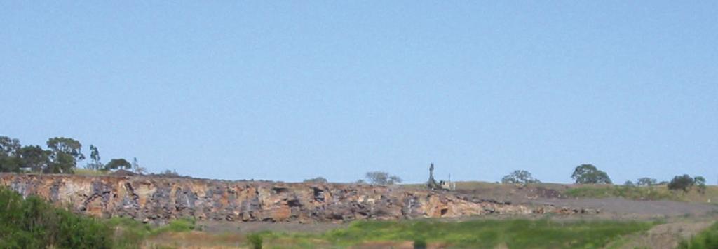
9 Rainfall / Evaporation (mm) Temperature (deg C) Proposed East Guyong Quarry Surface Water Management Jan Feb Mar Apr May Jun Jul Aug Sep Oct Nov Dec Month 0 Mean monthly rainfall - mm Mean monthly evaporation - mm Mean daily maximum temperature - deg C Figure 2 Long Term Climate Summary: Millthorpe (Rainfall & Temperature) and Orange (Evaporation) 2.2 Soils and Topography The site is currently used for grazing sheep and consists of grassed paddocks, characterised by shallow soils overlying basalt. On the surface of the ridge on the western portion of the property, basalt outcrops are visible which is consistent with the geological unit as described above. The soils of the East Guyong site are described as the Spring Hill Landscape (Soil Landscapes of the Bathurst 1: Sheet, Soil Conservation Service NSW, 1990) and are generally characterised by yellow podzolic soils. The geological unit across this area is tertiary volcanics from Mount Canobolas. The average depth to bedrock is 1 metre on crests with basalt floaters common on crests and side slopes. The soils within this landscape have a moderately erodible top-soil and low erodibility of sub-soils. A ridge runs through the site in a north-south direction. The average slope from the ridge top on the western portion of the site to the north-eastern corner, is approximately 6%. However, the slope from the top of ridge to the edge of the hill at the western boundary is very steep at approximately 13%. 2.3 Local Drainage The major drainage feature located to the west of the Hanson site is Lewis Ponds Creek (as shown Figure 4 attached) which forms part of the greater Macquarie River catchment. Lewis Ponds Creek flows from the south of the site, under the Mitchell Highway, then generally flows to the north and west of the site #21939-east guyong surface water report - main.doc July 2009 Page 4
10 Proposed East Guyong Quarry Surface Water Management All drainage from the western portion of the site (west of the ridge) flows directly to Lewis Ponds Creek. Runoff from the eastern portion of the site is currently collected in a series of farm dams, with the largest located near the eastern boundary of the site. Overflow from these dams follows the natural drainage lines, eventually entering Lewis Ponds Creek. 2.4 Existing Site Runoff Under existing conditions where the site is fully pervious and grassed, the NSW Farm Dams Assessment Guide indicates that, based on a harvestable rights multiplier for this area of 0.08 ML/ha, the average annual runoff would be approximately 10% of rainfall. Table 2.3 provides the estimated annual runoff from the site (148 ha) corresponding to average, wet and dry years. The non-linear response of the catchment to rainfall has been assessed utilising the Australian Water Balance Model (AWBM) to estimate the runoff volume from the site as shown in Table 2.3. Rainfall Year Table 2.3: Estimated Existing Site Runoff Rainfall (mm) Volume Rainfall (ML) Runoff Ratio Volume Runoff (ML) Average Year 805 1,190 10% th Percentile (wet) Year 1,120 1,658 15% th Percentile (dry) Year % 50 3 PROJECT DESCRPTON Hanson Construction is proposing a hard rock (basalt) quarry at the East Guyong Site, to progressively replace the existing Bathurst Quarry. The proposed layout of the site is shown on Figure 4 and, as indicated previously, extraction of rock will occur over seven stages which are summarised in Table 4.1. Table 4.1: Progressive Total Quarry Area Stage Total Quarry Area (ha) t is estimated that production from the East Guyong site will be up to 400,000 tonnes per year. The proposed quarrying operations will involve: removing overburden and stockpiling as vegetated mounds at various locations across the site; #21939-east guyong surface water report - main.doc July 2009 Page 5
11 Proposed East Guyong Quarry Surface Water Management blasting hard rock; processing, stockpiling and transportation of hard rock material. Development of the site will also include: construction of an access road from the Mitchell Highway to a work pad; construction of a level work pad approximately 6.7 ha for processing and stockpiling material; construction of associated drainage; water quality control measures including a Sediment Basin and sediment fencing; a Water Storage Dam for supply of water for dust suppression and on site purposes; installation of associated infrastructure including office, workshop and related facilities; installation of crushing plant and associated buildings; fuel storage area with associated bunding; and hydrocarbon-coated material stockpiling area with associated bunding. t is proposed to construct the access road, work pad, sediment basin, storage dam and associated drainage facilities about two years prior to commencement of quarry operations. At the same time the woodlots shown on Figure 4 would be established and irrigated using runoff collected in the storage dam. Once quarry operations commence, irrigation of the woodlots would cease. The crushing operation will be a dry process within an enclosed building requiring only about 400 kl/year for mist sprays. Consequently, the management and treatment of process water containing very fine particles will not be necessary. Dust suppression of the haul roads and trafficked areas of the site will be by a sprinkler system along the haul road, and by water cart as needed on other areas. Water will be sourced from the Water Storage Dam. 4 PROPOSED WATER MANAGEMENT 4.1 Water Management Objectives The purpose of this section is to present a Water Management Plan which will enable Hanson Construction Materials, East Guyong Quarry to meet the following water management objectives: 1. Primary control of sediment from the quarry by means of a sump within the quarry pit. 2. Primary control of sediment from the work pad and haul road by means of a sediment basin. 3. Secondary control of sediment by means of a water storage dam from which water will be extracted for site uses. 4. Treatment of stormwater runoff from hydrocarbon-coated aggregate stockpiles to remove oils and grease. 5. Bunding of a fuel storage area with the capacity to contain 110% of the tank volume. Figure 3 below shows a schematic of the proposed water management system for East Guyong Quarry while Figure 4 (A3 sheet located at the end of this report) shows the site layout #21939-east guyong surface water report - main.doc July 2009 Page 6
12 Proposed East Guyong Quarry Surface Water Management Quarry Pit Area (variable) Pit Sump Dust Suppression Undisturbed (Vegetated) Areas (variable) When TSS < 50 g/l Haul Road (variable)) Runoff Runoff Water Storage Dam (12 ML) Overflow Work Pad Area (6.7 ha) Runoff Sediment Basin (Minimum Volume 3 ML) LEWS PONDS CREEK Figure 3 Water Management Plan Schematic 4.2 Water Storage Dam A dam will be constructed in the north-east corner of the site as the main Water Storage Dam. This dam will capture and store rainfall runoff from undisturbed areas on the eastern portion of the site as well as discharge from the Sediment Basin and water pumped from the Pit Sump. Runoff from disturbed areas of the site including the haul road and work pad will be pre-treated by the Sediment Basin before flowing to the storage dam. This will ensure that no untreated runoff leaves the site. n order to comply with the harvestable right for the site, the capacity of the Water Storage dam will be limited to 12 ML. n accordance with the requirements set out in Table 6.1 of Soils and Construction: Mines and Quarries (DECC, 2008),the spillway for the dam has been sized to pass the estimated 100 year AR flow from the catchment. The estimated 100 year AR flow to the storage dam is 7.0 m 3 /s (Rational Method, Australian Rainfall & Runoff), therefore a 15 m long spillway will pass the 100 year flow at a depth of approximately 0.5 m. To provide adequate freeboard, the recommended minimum height of the embankment is 300 mm above the maximum water level (ie 800 mm above the level of the spillway). As detailed in Appendix B, under average rainfall conditions the Water Storage Dam would overflow between about 60 ML (at the start of operations) and 100 ML (towards the end of operations as a result of the increased impervious area in the quarry). The NSW Dam Safety Committee keeps a record of all large dams in NSW. The Dam Safety Committee considers the consequence of failure for dams and is able to provide requirements relating to the design, construction, operation, maintenance and surveillance of prescribed dams in NSW. The proposed storage dam on this site will not need to meet the requirements for the Dam Safety Committee to prescribe the dam because: the height of the dam wall is estimated to be 6 m, dam walls higher than 15 m require that the dam be prescribed; and #21939-east guyong surface water report - main.doc July 2009 Page 7
13 Proposed East Guyong Quarry Surface Water Management there is a low consequence of failure because there are no houses or quarry workings downstream that would be at risk if the dam were to fail. 4.3 Soil Stripping and Stockpiled Overburden As shown on Figure 4, the areas to be quarried are located on the ridge on the western portion of the site. t is proposed that soil removed from the surface as overburden will either be: stockpiled and set aside for use in site rehabilitation; or used for earthworks associated with constructing haul roads and the work pad area. All stockpiles will be located away from drainage lines. The preferred location for stockpiled overburden material is on the northern boundary of the site as shown as New Mound on Figure 4. Stockpiled soils will be stabilised to prevent erosion caused by wind and rainfall. Stabilisation will include planting vegetation and erecting silt fencing around the down hill section of the stockpiles to capture sediments transported by runoff. Stockpiles will be designed and stabilised in accordance with the guidelines detailed in Managing Urban Stormwater: Soils and Construction Volume 1 (Landcom, 2004) and Soils and Construction: Mines and Quarries (DECC, 2008). Standard erosion control measures for stockpiles sourced from Soils and Construction Volume 1 are included in Appendix A. 4.4 Separation of Clean and Dirty Runoff Figure 4 shows the proposed arrangements for separating clean runoff (from undisturbed areas) from dirty runoff (from disturbed areas) a more detailed description is included in Appendix A. Runoff from disturbed areas of the site will be treated to ensure sediment-laden water is not discharged from the site (discussed further detail in Section 4.6). "Clean" runoff, from areas not disturbed by site operations, will be diverted away from the proposed sediment basin to ensure that only dirty water is treated. 4.5 Runoff Management within the Quarry Pit A pit sump (or sumps) will be progressively established within the quarry excavation from Stage 1 and continue to be utilised through to Stage 7. All runoff within the excavated area for all stages of extraction will be directed to a pit sump. During long periods of wet weather (5 days or more) or large storms, the sump may overflow into the adjacent areas within the quarry. However, the capacity of the quarry excavation will be much greater than the expected maximum runoff volumes. According to the Bureau of Meteorology Climate Averages, the maximum recorded daily rainfall at Millthorpe is 110 mm (refer Table 2.1). As a comparison, Managing Urban Stormwater: Soils and Construction (Landcom 2004) lists a 90 th percentile 5 day rainfall depth for Bathurst of 35 mm. To estimate the maximum daily runoff volume that could be expected within the pit, the highest recorded daily rainfall depth of 110 mm was applied over the total excavation area at each stage. The runoff was calculated using the Rational Method as outlined in Australian Rainfall and Runoff (AR&R) while assuming a runoff coefficient of 0.85 (which is suitable for hard-packed, unvegetated earthen or rock surfaces) #21939-east guyong surface water report - main.doc July 2009 Page 8
14 Proposed East Guyong Quarry Surface Water Management The resulting runoff volumes at each stage of extraction for the maximum recorded daily rainfall are summarised below: Table 5.1: Quarry Runoff Due to Maximum Rain Day (110 mm) Stage Area (ha) Volume (ML) As shown, the runoff in the quarry due to the maximum recorded rain day would range from 1.3 ML at Stage 1 to 15.6 ML at Stage 7 or a depth across the total extraction area of 0.09 m. Therefore, although these runoff volumes appear substantial, they would easily be contained within the quarry pit. As necessary to facilitate quarry operations water will be pumped from the pit sump to the Water Storage Dam. Analysis of the pit sump water at the existing hard rock quarry site near Bathurst indicates that the runoff within the quarry is of good quality exhibiting a neutral ph, a low turbidity level (10 NTU) and a low salinity (EC 350 µs/cm). t is expected that the quality of runoff within the East Guyong quarry would be similar to that at the existing Bathurst Quarry. Therefore, water quality factors are not expected to pose any constraints on managing excess water from the quarry sump. DECC has indicated any operating licence for the site will require that controlled water releases does not contain more than 50 mg/l of suspended sediments. n order to ensure that this requirement is met, a visual comparison of sump water with a control sample will be carried out prior to pumping from the Pit Sump to the Water Storage Dam. This will ensure that any ensuing overflow from the dam (which may occur as a result of additional water from the Pit Sump), meets the DECC requirements. 4.6 Water Management from the Crushing/Stockpiling Area The crushing plant and stockpiled materials will be located on a level work area (work pad) of approximately 6.7 ha. Stormwater runoff from this area and the haul road will potentially carry sediments and will be treated by the Sediment Basin located at the north east corner of the work pad before flowing to the Water Storage Dam. This will ensure that all runoff from this area is treated before leaving the site. Runoff from surrounding, undisturbed areas will be redirected away from the work pad by bunding and catch drains. This will ensure that only dirty water is treated. The primary source of sediment from the work-pad area will be particles larger than 0.02mm. Accordingly the sediment basin has been designed in accordance with the procedures for a basin to capture coarse sediments as set out in Chapter 6 of Managing Urban Stormwater: Soils and Construction (Landcom, 2004). n accordance with the design standards set out in Table 6.1 of #21939-east guyong surface water report - main.doc July 2009 Page 9
15 Proposed East Guyong Quarry Surface Water Management Mines and Quarries (DECC, 2008) the Sediment Basin has been designed for the peak flow from a 2 year average recurrence interval (AR) storm. n 2004, during early consultation for this project, the Department of Environment and Conservation (DEC) advised that the sediment basin should also have sufficient capacity to contain runoff from the 20 year AR, 2 hour storm event. Details of the design of the Sediment Basin to meet these design requirements is set out in Appendix A and summarised in Table 4.2. Table 4.2: Summary of Sediment Basin Details Catchment Area Draining to Sediment Basin 8.35 ha Peak Flow Rate (Q 1 year) 0.18 m 3 /s Peak Flow Rate (Q 20 year) 0.91 m 3 /s Peak Flow Rate (Q 100 year) 1.80 m 3 /s Particle Size 0.02 mm Minimum Basin Surface Area 740 m 2 Spillway Length Volume to contain 20 year AR, 2 hour storm Volume to contain 50 year AR, 2 hour storm 8.5 m 3 ML 3.5 ML 4.7 Runoff Management from Hydrocarbon-Coated Aggregate Stockpiles of various sized aggregates will be located on the work pad area (shown Figure 4). There will also be stockpiles containing aggregate coated with hydrocarbon, which will be stored on specifically designated areas. The hydrocarbon-coated aggregate stockpile areas will have a concrete base with bunding to prevent runoff containing hydrocarbons leaving the site and infiltrating the surrounding soil. The runoff from the hydrocarbon-coated stockpiles will be treated using an oil/water separation unit such as a corrugated plate interceptor (CP) unit or alternatively a hydrocarbon spillage pond. Oils and hydrocarbons will be removed to a licensed treatment facility. Treated water will be stored in the Water Storage Dam to be reused for dust suppression or irrigation. 4.8 Entrance/Haul Road Runoff Management The entrance to the quarry site off the Mitchell Highway is situated on a ridge that slopes towards the operations area. The road will be bitumen sealed and road runoff will be directed to the storage dam. Near the entrance to the work pad a grate will be installed to remove loose sediment from trucks leaving the site. 4.9 Fuel Storage Diesel will be stored onsite in a kl fuel storage tank located in a bunded and roofed area. All fuel storage will be constructed in accordance with Australian Standards for storage of fuels (AS , AS , AS ). The net capacity of a bunded compound in a tank storage facility will be at least 110% of the net capacity of the largest tank #21939-east guyong surface water report - main.doc July 2009 Page 10
16 Proposed East Guyong Quarry Surface Water Management 4.10 Water Supply and Usage The main sources for water supply for the site will be the Water Storage Dam (storage volume 12 ML). Water will be required for: irrigation of establishing wood lots (for approximately 24 months prior to commencement of quarrying); dust suppression of haul roads and active sections of the work pad; dust suppression associated with the crushing process. A water balance analysis using 26 years of daily climatic data has been undertaken for the proposed East Guyong Quarry operations. Details of this analysis are included in Appendix B. The modelling makes generous provision for irrigation of the woodlots and water for dust suppression. The model includes an assessment of the water required for dust suppression based on mine site investigations by Thompson and Visser (2002). For modelling purposes the results of this work are represented by providing water for dust suppression on a daily at a rate of 1.5 times the evaporation rate less any incident rainfall with a maximum depth of watering of 10 mm/day. For the climate at East Guyong, this water application rate converts to an average annual depth of about 1,200 mm. Table 4.3 provides a summary of the results of the water balance modelling which sets out for each stage of quarry development the percentage of time that the full water demand can be met: On average throughout the 26 years of analysis (column labelled Average ); During a 1 in 10 dry year (column labelled Dry ); During a 1 in 10 wet year (column labelled Wet ). Stage Table 4.3: Summary of Water Balance Modelling Results Quarry Pit Area rrigated Woodlot Area Average Demand Percent of Time Full Demand is Met (ha) (ha) (ML/year) Average Dry Wet % 100% 100% % 90% 100% % 89% 100% % 92% 100% % 89% 100% % 89% 100% The results in Table 4.3 show that: The proposed water management system will be able to provide all the water demands of the quarry operation better than 96% of the time on average; Even in a 1 in 10 dry year the proposed water management system will be able to provide all the water demands of the quarry operation more than 89% of the time. Although the modelling indicates that the assessed water demand will not be fully met all of the time, particularly in a drought year, this is unlikely to cause any operational problems because: The model makes a generous allowance for water application for dust suppression purposes and is therefore likely to over-estimate the actual water requirements; n the event that water levels in the Water Supply Dam reach less than, say, 25%, a reduction in water usage by 25% would achieve adequate dust suppression and allow full demand to be met; #21939-east guyong surface water report - main.doc July 2009 Page 11
17 Proposed East Guyong Quarry Surface Water Management Alternatively, in extremely dry conditions, the quarry could utilise chemical binding agents that only require a small amount of water to apply Site Discharge n addition to providing a means of assessing the reliability of supply for dust suppression and other purposes, the water balance model has also been used to assess the expected frequency and volume of discharge from the Water Storage Dam. Table 4.4 provides a summary of the modelling results at each stage of quarry development for average, dry and wet conditions (as defined in Section 4.10 above). For modelling purposes, an overflow event has been defined as a period of up to 10 days in which there is runoff continuously except for a break of one day. This definition reflects the fact that, once the dam is full, the model counts overflow as occurring on subsequent days when there is no demand but even a trivial addition to the dam, even rainfall. Table 4.4: Summary of Estimated Overflow Volumes and Events Stage Overflow (ML/Year) Overflow (Events/Year) Average Dry Wet Average Dry Wet The results in Table 4.4 indicate that as the quarry develops, increased runoff from bare quarry surface will lead to increased overflow from the Water Storage Dam. The table also indicates that the overflow volume and number of overflow events will be highly dependent on the rainfall in any year. 5 MONTORNG AND MANTENANCE REQUREMENTS A Water Management Plan for the proposed East Guyong Quarry will be prepared following approval of the project. The Plan will include the following components for managing stormwater runoff from the site: Storage dam Sedimentation basin Oil separation unit The monitoring and maintenance requirements for these elements of the water management system are described below. 5.1 Sediment Basin The Sediment Basin will include a perforated riser piped outlet which will gradually empty the basin between rainfall events, ensuring that there is adequate capacity to receive the next runoff event. Monitoring of the Sediment Basin will be required to ensure that: Trapped sediments are removed when depth is greater than 0.5 m; #21939-east guyong surface water report - main.doc July 2009 Page 12
18 Proposed East Guyong Quarry Surface Water Management Quality of water leaving the sediment basin meets the treatment objective (TSS<50 mg/l). The sediment levels within the sediment dam will be inspected monthly, and the removal of sediments to a suitably protected stockpile area will be organised when sediments reach a depth of 0.5 m (indicated by a permanent marker on the side of the basin). Water quality monitoring of outflows from the Sediment Basin should be undertaken quarterly to ensure that the basin is providing sufficient settling of sediments. Water samples taken from the outlet downstream of the basin will be tested by a NATA registered laboratory. 5.2 Oil Separation Unit The oil separation unit will treat runoff from the hydrocarbon-coated aggregate area. This unit will be inspected regularly and accumulated oils will be removed to a licensed treatment facility when the unit reaches capacity. Water from the oil separation unit will be discharged to the Water Storage Dam for re-use. 5.3 Storage Dam n addition to providing a source of water for site operations, the Water Storage Dam will provide the final polishing and treatment of stormwater runoff from the whole site. As described in Appendix B, water from this dam will be reused for dust suppression. As the only point of discharge from the site will be from this dam, monitoring will be required to ensure that the water quality of the dam meets the requirements of the DECC. Water samples will be analysed quarterly to ensure that there is no change in the ph and that total suspended solids are less than 50 mg/l. Samples will be analysed by a NATA registered laboratory. 6 WATER LCENCNG As described above, the site will have three locations at which surface water will be held for various purposes: A Pit Sump (or sumps) within the quarry pit which will provide temporary storage of water for sediment settlement. Because the sump will primarily fulfil a pollution control function and water collected in the sump will be discharged to the Water Storage Dam, it is exempt from consideration under the Farm Dams Policy. A Sediment Basin that will collect and treat runoff from the Work Pad and haul road areas. Because the sediment basin will primarily fulfil a pollution control function and water collected in the basin will be discharged to the Water Storage Dam, it is exempt from consideration under the Farm Dams Policy. A Water Storage Dam that will collect runoff from a total area of about 73 ha (including the Quarry Pit and Work Pad). The remaining area of the property in which the quarry will be located (75 ha) will discharge freely. The Water Storage Dam will have a capacity of 12 ML which complies with the harvestable right for the site (0.08 ML/ha x 148 ha). Accordingly, no water licence will be required for the construction of this dam. The Special Supplement to the Government Gazette Number 159 (date 19 December 2008) places an embargo on any applications for Part 5 Water Licences in a number of groundwater management areas including the Orange Basalt area on the edge of which the site is located #21939-east guyong surface water report - main.doc July 2009 Page 13
19 Proposed East Guyong Quarry Surface Water Management The embargo provides an exemption for a dewatering activity provided that the annual extraction does not exceed 10 ML per year. t is anticipated that minor quantities of water may seep into the pit immediately following rainfall events as a result of infiltration into the immediately adjoining landscape. This localised interflow will not be groundwater and does not therefore warrant consideration under the exemption to the current embargo. 7 SUMMARY The proposed layout and location of surface water management of the East Guyong Quarry is shown on the Water Management Plan (Figure 4 attached). t is proposed that the following water quality protection measures be incorporated in the operation of the site: All runoff from the eastern portion of the site including the quarry and work pad areas will be stored in a 12 ML Water Storage Dam to be located in the north eastern corner. Quarry runoff will be collected and stored in Pit Sump/s and subsequently pumped to the Water Storage Dam. Runoff from work areas will be treated by a Sediment Basin with a minimum volume of 3.0 ML. Clean runoff will be diverted away from work areas to the Water Storage Dam. Runoff from hydrocarbon-coated aggregate stockpile area will be treated using an oil/water separation unit. Water from this unit will be directed to the Water Storage Dam. Fuel storage areas will be bunded in accordance with regulatory requirements. The haul road between the highway and Work Pad and bitumen sealed and all runoff will be directed to the Water Storage Dam. Monitoring of the water quality in the Sediment Basin and the Water Storage Dam will be undertaken to ensure that the quality of any discharge from the site meets the DECC s requirements. By incorporating the water management measures into the operations of the site as outlined in this report, Hanson Construction Materials will ensure that: Sufficient water for dust suppression will be available from runoff held in the on-site storage; There will be no discharge of untreated runoff from the site; and All controlled discharge from the site will meet DECC s water quality requirements #21939-east guyong surface water report - main.doc July 2009 Page 14
20 Proposed East Guyong Quarry Surface Water Management 8 REFERENCES Bureau of Meteorology (2001), Climatic Averages of Australia, Bureau of Meteorology Website, ( Coffey Geosciences (2002), Report No. E1268/1-AC, Proposed East Guyong Quarry, Groundwater nvestigation for Pioneer Construction Materials. DECC (2008), Soils and Construction: Mines and Quarries, Volume 2E, Managing Urban Stormwater, DECC/Sydney Metropolitan CMA. Grayson R.B., et al (1996), Hydrological Recipes: Estimation Techniques in Australian Hydrology, CRC for Catchment Hydrology, Melbourne. nstitution of Engineers Australia (2001), Australian Rainfall & Runoff, EAust, Canberra. Landcom (2004), Managing Urban Stormwater: Soils and Construction, NSW Government. NSW Department of Land and Water Conservation (1999), Farm Dams Assessment Guide. NSW Government Gazette No 159 (2008), Special Supplement, 19 December #21939-east guyong surface water report - main.doc July 2009 Page 15

21 D Revise Storage Dam Size 6/7/09 jwallis c Revise Storage Dam Size 23/5/07 D
22 HANSON CONSTRUCTON MATERALS EAST GUYONG QUARRY Appendix A Sediment Basin and Diversion Channel Design Final July 2009
23 Proposed East Guyong Quarry Surface Water Management Appendix B Sediment Basin and Diversion Channel Design #21939-East Guyong Surface Water Report-App A.doc 16 July 2009 ( i )
24 Proposed East Guyong Quarry Surface Water Management Appendix B Sediment Basin and Diversion Channel Design Table of Contents A.1. CATCHMENT AREAS... 1 A.2. CLMATE... 1 A.3. RUNOFF CALCULATONS... 2 A.4. WATER MANAGEMENT FROM THE CRUSHNG/STOCKPLNG AREA (WORK PAD AREA)... 2 A.5. STORMWATER DRANAGE... 3 A.6. REFERENCES... 4 List of Figures Figure A-1 Figure A-2 Figure A-3 Drainage Layout and Catchments Typical Sediment Basin Arrangement Typical Silt Fence Arrangement List of Tables Table A 1: East Guyong Catchment Areas... 1 Table A 2: Site Rainfall ntensity (mm/h)... 1 Table A 3: Estimated Peak Runoff Rates from Catchment Areas... 2 Table A 4: Summary of Sediment Basin Details... 3 Table A 5: Drainage Channel Dimensions #21939-East Guyong Surface Water Report-App A.doc ( ii )
25 Proposed East Guyong Quarry Surface Water Management Appendix B Sediment Basin and Diversion Channel Design A.1. CATCHMENT AREAS Runoff from the work pad area and haul road will be directed to a Sediment Basin for treatment. The Sediment Basin will be located close to the north east corner of the work pad area. Treated water from the Sediment Basin will be stored in the Water Storage Dam to be located about 230 m east of the work pad area. Runoff from the areas uphill from the Sediment Basin will be directed around the Sediment Basin to the proposed Water Storage Dam located near the eastern boundary of the site. Details of the Water Storage Dam (12 ML) are included in Appendix B. Table A 1 below shows a breakdown of the catchment areas that will drain to the Sediment Basin. Table A 1: East Guyong Catchment Areas Description Slope Length (m) Area (ha) Work Pad 1% Haul Road 4% The catchment areas detailed above are shown on Figure A-1 attached. A.2. CLMATE Rainfall intensity data for the site has been derived by means of the data and procedures set out in Australian Rainfall and Runoff, Volume 2 (EAust, 1987) and the RANER program developed by the then NSW Department of Conservation and Land. Table A 2 summarises the rainfall intensity of relevant storm durations and average recurrence intervals (AR) at the site. Table A 2: Site Rainfall ntensity (mm/h) AR Duration (minutes) (years) #21939-East Guyong Surface Water Report-App A.doc Page 1
26 Proposed East Guyong Quarry Surface Water Management Appendix B Sediment Basin and Diversion Channel Design A.3. RUNOFF CALCULATONS Runoff calculations for the site were undertaken in accordance with the Probabilistic Rational Method as set out in Australian Rainfall Runoff (AR&R) (EAust 2001) using runoff coefficients taken from Table F3 of Managing Urban Stormwater: Soils and Construction (Landcom 2004) and adjustments for storm AR from Table 5.1 of AR&R. The estimated peak flow rates from each catchment area are set out in Table A 3 below. Table A 3: Estimated Peak Runoff Rates from Catchment Areas Catchment Peak Flow Rate m 3 /s 1 year AR 2 year AR 20 year AR 100 year AR Work Pad Haul Road Combined Areas* * The peak flow rate from the combined catchment areas provides a conservative estimate of the peak storm runoff to the Sediment Basin. A.4. WATER MANAGEMENT FROM THE CRUSHNG/STOCKPLNG AREA (WORK PAD AREA) Fine particles generated from the crushing plant will be trapped using a foam dust suppressant. The crushers will also be enclosed, preventing the dispersion of fine particles to the outdoor area of the work pad. Therefore, a Type C sediment basin is considered appropriate for the site because the sediments contained in site runoff will have less than 33% fines. The sediment basin would operate as a dry basin, (ie it will empty between rainfall events so that the basin will have sufficient capacity to treat the next rainfall event). The sediment basin has been designed to meet the following attributes: Type C basin in accordance with the design procedures in Chapter 6 of Managing Urban Stormwater Soils and Construction; Particle size 0.02 mm diameter; Treatable flow rate for the 2 year AR storm event (0.69 m 3 /s) (in accordance with the requirements set out in Table 6.1 of Soils and Construction: Mines and Quarries (DECC, 2008); Basin Spillway to pass the 100 year AR flow at a maximum depth of flow over the spillway of 0.3 m; Containment of the 20 year AR, 2 hour duration storm event (as required by Central West office of DEC (now DECC) in ES review in 2004) #21939-East Guyong Surface Water Report-App A.doc Page 2
27 Proposed East Guyong Quarry Surface Water Management Appendix B Sediment Basin and Diversion Channel Design Table A 4: Summary of Sediment Basin Details Catchment area draining to Sediment Basin 7.0 ha Peak Flow Rate (2 year AR) 0.7 m 3 /s Peak Flow Rate (100 year AR) 3.8 m 3 /s Particle Size 0.02 mm Minimum Basin Surface Area 2,500 m 2 Spillway Length 8.5 m Volume to contain 20 year AR, 2 hour storm 3 ML Volume to contain 50 year AR, 2 hour storm 3.5 ML The minimum surface area of 2,500 m 2 (as shown in Table A 4) is the area required to achieve the required settlement of particles of 0.02 mm in runoff from the 2 year AR storm. A larger surface area (which may be required to meet the minimum containment volume of 3.0 ML) would improve the level of sediment removal from all storm events. Construction of a sediment basin to contain the 20 year AR, 2 hour storm (as required by DECC) would contain 85% of runoff from the work pad for the 50 year AR 2 hour storm event. Although not specifically stated by DECC, the Sediment Basin has been designed to gradually empty over time to ensure that sufficient capacity is available to contain the next storm event. Therefore, it is recommended that a dry sediment basin be constructed with a constricted outlet discharging to the Water Storage Dam. A typical arrangement sourced from Managing Urban Stormwater Soils & Construction (Landcom, 2004) is attached as Figure A-2. A.5. STORMWATER DRANAGE Stormwater from catchments other than the work pad will be directed around the Sediment Basin to the Water Storage Dam (as shown on Figure A-1 attached). The estimated drainage channel requirements to convey the peak 20 year AR runoff from the Catchment Areas 1 and 2 are detailed below: Table A 5: Drainage Channel Dimensions Area 1 Area 2 Longitudinal slope of drain * 2% 2% Flow Rate (m 3 /s) Base Width (m) Side slopes (h:v) 3:1 3:1 Depth (includes 0.15 m freeboard) * where the longitudinal slope of the drain is greater than 2%, armouring of the drainage channel will be required to prevent erosion or scouring of the drain #21939-East Guyong Surface Water Report-App A.doc Page 3
28 Proposed East Guyong Quarry Surface Water Management Appendix B Sediment Basin and Diversion Channel Design A.6. REFERENCES DECC (2008), Soils and Construction: Volume 2E Mines and Quarries nstitution of Engineers Australia (2001), Australian Rainfall & Runoff, EAust, Canberra. Landcom (2004), Managing Urban Stormwater: Soils & Construction, NSW Government #21939-East Guyong Surface Water Report-App A.doc Page 4
29 Proposed East Guyong Quarry Surface Water Management Appendix B Sediment Basin and Diversion Channel Design Figure A-1 Catchment Drainage #21939-East Guyong Surface Water Report-App A.doc Page 5
30 Proposed East Guyong Quarry Surface Water Management Appendix B Sediment Basin and Diversion Channel Design Figure A-2 Typical Sediment Basin Arrangement #21939-East Guyong Surface Water Report-App A.doc Page 6
31 Proposed East Guyong Quarry Surface Water Management Appendix B Sediment Basin and Diversion Channel Design Figure A-3 Typical Silt Fence Arrangement #21939-East Guyong Surface Water Report-App A.doc Page 7

32 HANSON CONSTRUCTON MATERALS EAST GUYONG QUARRY Appendix B Water Balance Analysis Final July 2009
33 Hanson Construction Materials Proposed East Guyong Quarry Appendix B Water Balance Analysis Table of Contents B.1. NTRODUCTON... 1 B.2. WATER BALANCE MODEL... 2 B.2.1 CLMATE DATA... 3 B.2.2 CATCHMENT RUNOFF... 4 B.2.3 WATER STORAGES... 6 B.2.4 WATER USE... 6 B.2.5 SYSTEM OPERATON... 7 B.3. MODEL RESULTS... 7 B.4. RECOMMENDATON... 9 B.5. REFERENCES... 9 List of Figures Figure B 1: Water Management System... 1 Figure B 2: Structure of the AWBM Rainfall-Runoff Model... 2 Figure B 3: Long Term Climate Summary: Millthorpe (Rainfall & Temperature) and Orange (Evaporation)... 3 Figure B 4: Site Catchment Areas List of Tables Table B 1: Summary of Climate Analysis... 4 Table B 2: AWBM Model Parameters... 5 Table B 3: Catchment Area and Runoff Summary... 5 Table B 4: ndicative Haul Road Areas at Quarrying Stages... 7 Table B 5: Water Balance Result Summary... 8 Table B 6: Summary of Estimated Overflow Volumes and Events #21939-East Guyong Surface Water Report-App B.doc 16 July 2009 ( ii )
34 Hanson Construction Materials Proposed East Guyong Quarry Appendix B Water Balance Analysis B.1. NTRODUCTON Hanson Construction Materials are proposing a new basalt quarry at East Guyong to replace existing operations at Bathurst. Hanson has developed a Quarry Plan that extends over a 25 to 50 year period and provides seven stages for development of the East Guyong Quarry. For purposes of establishing the overall performance of the water management systems associated with the proposed East Guyong Quarry, a surface water management model has been developed to represent the runoff, transfer and water storage systems within the site as shown in Figure B 1. Quarry Pit Area (Variable) Undisturbed (Vegetated) Areas (Variable) Pit Sump When TSS<50mg/L Dust Suppression Runoff Haul Road Runoff Water Storage Dam (12 ML) Overflow Work Pad Area (6.7 ha) Runoff Sediment Basin (Minimum Volume 3 ML) LEWS PONDS CREEK Figure B 1: Water Management System The model for assessment of the water balance for the proposed East Guyong Quarry project accounts for: surface runoff from the contributing catchments into the Sediment Dam, the Quarry Pit Sump and the Water Storage Dam at each stage of development; rainfall onto, and evaporation from, the surface of the various storages; extraction of water for dust suppression purposes (on haul roads and access roads); water usage within the crusher; and controlled discharge from the Water Storage Dam in the event that the maximum target water level is exceeded. The model uses daily historic climate data (rainfall, and evaporation), keeps account of all daily inputs and outputs and provides a summary of the volume and frequency of overflows. Further details of the main elements of the model are set out below #21939-East Guyong Surface Water Report-App B.doc Page 1
35 Hanson Construction Materials Proposed East Guyong Quarry Appendix B Water Balance Analysis The objective of the water balance model is to assess the adequacy of the water management system to meet the water demands of the site and to identify the approximate frequency and volume of discharge. B.2. WATER BALANCE MODEL A daily water balance model was developed for the site to incorporate the estimated water inputs due to surface runoff generated by rainfall and water usage due to dust suppression of haul roads and stockpile areas. Surface runoff for the daily water balance modelling was estimated using the Australian Water Balance Model (AWBM), which is part of the CRC for Catchment Hydrology s Rainfall Runoff Library (RRL) (CRC for Catchment Hydrology, 2004). AWBM is a catchment water balance program, developed by Walter Boughton for Australian conditions, that uses rainfall and evaporation data to generate catchment daily runoff. Figure B 2 below (reproduced from the RRL User s Guide) provides a schematic of the AWBM rainfall-runoff model. The program represents a catchment as three surface moisture stores with different storage and runoff characteristics. Rainfall is added daily to each of the three surface moisture stores and evapotranspiration is subtracted from the stores. Runoff occurs when there is excess moisture in any of the stores. Figure B 2: Structure of the AWBM Rainfall-Runoff Model (Reproduced from the Rainfall Runoff Library User s Guide (CRC for Catchment Hydrology, 2004) #21939-East Guyong Surface Water Report-App B.doc Page 2
36 Rainfall / Evaporation (mm) Temperature (deg C) Hanson Construction Materials Proposed East Guyong Quarry Appendix B Water Balance Analysis B.2.1 Climate Data Climate data was obtained from the Bureau of Meteorology for the following stations: Daily rainfall data for Millthorpe (nala) ( ) Daily evaporation data for Orange Agricultural nstitute ( ) Figure B 3 below shows a summary of the long term climate averages that are relevant for the East Guyong site. This shows that on average, rainfall exceeds evaporation during winter and that the average monthly rainfall is generally in the range of 50 mm to 80 mm Jan Feb Mar Apr May Jun Jul Aug Sep Oct Nov Dec Month 0 Mean monthly rainfall - mm Mean monthly evaporation - mm Mean daily maximum temperature - deg C Figure B 3: Long Term Climate Summary: Millthorpe (Rainfall & Temperature) and Orange (Evaporation) Table B 1 provides a summary of the statistical analysis of the full rainfall record for Millthorpe. This shows that dry (10 percentile) rainfall years occurred during 1979 and 2002, average rainfall occurred during 1949 and 1995, and that wet (90 percentile) rainfall years occurred during 1920 and The daily rainfall record for the period was adopted for the water balance modelling purposes. This period of the climatic record includes average, drier than average and wetter than average rainfall periods for testing the performance of the proposed water management system at the East Guyong site #21939-East Guyong Surface Water Report-App B.doc Page 3
37 Hanson Construction Materials Proposed East Guyong Quarry Appendix B Water Balance Analysis Table B 1: Summary of Climate Analysis Parameter Annual Rainfall (mm) Occurrence Mean Percentile 10% , 2002 Percentile 20% Percentile 30% Percentile 40% Percentile 50% , 1995 Percentile 60% Percentile 70% Percentile 80% Percentile 90% , 1984 B.2.2 Catchment Runoff The parameters adopted to generate runoff for the East Guyong water balance model were derived from the a number of previous studies in which an AWBM model was calibrated using runoff and climate data to derive model parameters that reflected the relationship between rainfall and runoff: Kingdon Ponds at Parkville (approximately 725 mm average annual rainfall); Pokolbin Creek at Cessnock (approximately 725 mm average annual rainfall) ACARP Project No. C7007: Water Quality Discharge Predictions for Final Void and Spoil Catchments (2001). Prepared by PPK Environmental & nfrastructure. Boughton, W. C. and Chiew, F.H.S., (2003), Calibrations of the AWBM for Use on Ungauged Catchments : Technical Report 03/15, Cooperative Research Centre for Catchment Hydrology, Melbourne. By reference to other published data (Boughton and Chiew, 2003, ACARP, 2001) the calibrated model parameters for natural catchments and disturbed landscapes were used as the basis for selecting parameters (Table B 2) to reflect the differences in hydrologic characteristics of different surface types. Specific factors taken into account were: Surfaces where vegetation has been removed will have reduced evapotranspiration compared to natural bushland. For surfaces without vegetation the effective evaporation has been taken to be 85% of normal (Boughton, pers com 2008); The surface within the extraction area will be exposed basalt, which will have negligible soil moisture storage capacity for absorption of rainfall. n addition, evaporation loss will occur only while ever the immediate surface is wet. For undisturbed areas of the site, the model parameters were adjusted to give an average annual runoff that is consistent with the runoff implied in the Farm Dams Assessment Guide of 10% of rainfall; #21939-East Guyong Surface Water Report-App B.doc Page 4
38 Hanson Construction Materials Proposed East Guyong Quarry Appendix B Water Balance Analysis The parameter Ksurf was reduced to zero for all model runs for quarry surfaces to account for the absence of any surface runoff routing effects in small catchments. Table B 2: AWBM Model Parameters Parameters Land Use Natural Work Pad & Haul Road Quarry A A A C C C BF Kbase Ksurf Evap% 100% 85% 85% The quarry will be developed in a series of stages, commencing with an initial establishment phase in which the facilities will be established, but no quarrying will occur. The average annual runoff volume for each catchment within the site including the each stage of the quarry are summarised in Table B 3 below. Figure B 4 (attached) shows the location of catchments draining to storages within the site apart from the catchments within the pit. Catchment Areas Table B 3: Catchment Area and Runoff Summary Stage Haul Road & Sales Area Work Pad Natural Catchment Quarry Pit Runoff Haul Road & Sales Area Work Pad Natural Catchment Quarry Pit Total #21939-East Guyong Surface Water Report-App B.doc Page 5
39 Hanson Construction Materials Proposed East Guyong Quarry Appendix B Water Balance Analysis B.2.3 Water Storages Three water storage areas have been included in the water balance model: Quarry Pit Sump The Quarry Pit Sump is the low point within the quarry that will collect and hold rainfall runoff. The primary function of the Pit Sump will be for pollution control by providing for settlement of sediment in the runoff. The catchment area contributing to the Pit Sump will vary depending on the stage of quarry operations. For the purpose of the water balance model, the pit sump acts as a temporary storage of 2 ML from which water is transferred to the Water Storage Dam. The lowest point of quarrying at East Guyong will not reach the groundwater level. The assessment undertaken by Coffey Geosciences (2002) indicates that it is unlikely that seepage from the quarry pit would occur. Therefore no inflow or outflow from the Quarry Pit Sump due to groundwater has been included in the model. Sediment Basin The Sediment Basin, which will collect runoff from the work pad and haul road has been sized for sediment control purposes in accordance with the relevant design guidelines (see Appendix A). The Sediment Basin will provide temporary storage for approximately 3 ML and will form part of the catchment contributing to the Water Storage Dam. Water Storage Dam The catchment areas contributing the Water Storage Dam include the areas draining to the Sediment Basin and the undisturbed catchment areas (Catchment Area 1, 2 and 3 on Figure B 4 together with those areas that will eventually be quarried. The average depth of the storage has been assumed to be 8 m. The adopted size of the Water Storage Dam (12 ML) has been selected to ensure that the volume of water storage on site complies with the NSW Farm Dams Policy. B.2.4 Water Use At the proposed East Guyong Quarry, water will be required for: dust suppression of haul roads; and dust suppression associated with the crushing process. Haul Roads The water usage for dust suppression has been calculated based on a daily basis using the methods described by Thompson & Viser (2002) where the daily water volume (L) = 1.25 x evaporation (mm) - rainfall (mm) x area (m 2 ). The estimated area of haul road within the quarry that have been included in the water use calculations within the water balance model are included in Table B 3 above. The model indicates that the average water requirement for dust suppression on the haul roads and other areas is about 1,200 mm (12 ML/ha). Accordingly the water requirement for dust suppression will rise from about 11 ML/year in Stage 1 to about 18 ML/year in Stage 7, reflecting the increased length of haul road as the quarry expands. The water demand for dust suppression could be reduced through use of dust suppression products (binders) that can reportedly reduce water required for dust suppression by 50% to 80% #21939-East Guyong Surface Water Report-App B.doc Page 6
40 Hanson Construction Materials Proposed East Guyong Quarry Appendix B Water Balance Analysis Table B 4: ndicative Haul Road Areas at Quarrying Stages Quarry Stage Haul Road (ha) Stage Stage Stage Stage Stage Crushing Process The crushing process to be used at East Guyong will be a dry process with the crushers enclosed to minimise dust. Some water will be required for fine misting to contain dust within the buildings. An estimate based on the existing water use for crushing at Bathurst Quarry is 400 kl/year. B.2.5 System Operation The water balance model has been configured to allow the water storages to operate in the following manner: The Sediment Dam drains by gravity to the Water Supply Dam; Water is pumped from the Quarry Pit Sump to the Water Supply Dam at a nominal rate of 1 ML/day; Overflow from the Water Supply Dam occurs when the maximum volume of 12 ML is exceeded. B.3. MODEL RESULTS The water balance model was run for a daily climatic record of 26 years. Table B 5 provides a summary of the ability of the water management system to provide water for operational needs at various stages of the quarry development while Table B 6 summarises the expected overflow volume and number of events. For modelling purposes, an overflow event has been defined as a period of up to 10 days in which there is runoff continuously except for a break of one day. This definition reflects the fact that, once the dam is full, the model counts overflow as occurring on subsequent days when there is no demand but even a trivial addition to the dam, even rainfall #21939-East Guyong Surface Water Report-App B.doc Page 7
41 Hanson Construction Materials Proposed East Guyong Quarry Appendix B Water Balance Analysis Stage Quarry Pit Area Table B 5: Water Balance Result Summary rrigated Woodlot Area Average Demand Percent of Time Full Demand is Met (ha) (ha) (ML/year) Average Dry Wet % 100% 100% % 90% 100% % 89% 100% % 92% 100% % 89% 100% % 89% 100% Table B 6: Summary of Estimated Overflow Volumes and Events Stage Overflow (ML/Year) Overflow (Events/Year) Average Dry Wet Average Dry Wet The results in Table B 5 show that: The proposed water management system will be able to provide all the water demands of the quarry operation better than 96% of the time on average; Even in a 1 in 10 dry year the proposed water management system will be able to provide all the water demands of the quarry operation more than 89% of the time. Although the modelling indicates that the assessed water demand will not be fully met all of the time, particularly in a drought year, this is unlikely to cause any operational problems because: The model makes a generous allowance for water application for dust suppression purposes and is therefore likely to over-estimate the actual water requirements; n the event that water levels in the Water Supply Dam reach less than, say, 25%, a reduction in water usage by 25% would achieve adequate dust suppression and allow full demand to be met; Alternatively, in extremely dry conditions, the quarry could utilise chemical binding agents that only require a small amount of water to apply. The results in Table B 6 indicate that as the quarry develops, increased runoff from bare quarry surface will lead to increased overflow from the Water Storage Dam. The table also indicates that the overflow volume and number of overflow events will be highly dependent on the rainfall in any year #21939-East Guyong Surface Water Report-App B.doc Page 8
42 Hanson Construction Materials Proposed East Guyong Quarry Appendix B Water Balance Analysis B.4. CONCLUSONS The water balance model developed for the East Guyong Quarry has been utilised assess the ability of a 12 ML Water Storage Dam to meet the water requirements associated with quarrying operations. The model indicates that by collecting runoff from the quarry pit, the work pad area, haul roads and the natural catchment area contributing to the dam (total area about 73 ha) the proposed dam will be capable of supplying all the water required for site operations under all except a few days per year on average. Although the model indicates that there will be some short periods of water shortage, in practice, a small reduction in water for dust suppression once the dam reaches 25% capacity would allow the quarry to meet all its operational needs. B.5. REFERENCES Andy Bailey, (2006) Hanson Construction Materials, Bathurst Quarry (pers. comm.), October 2006 Lyall & Macoun Consulting Engineers (1998). Catchment Management Study: Morpeth-Tenambit, Woodberry and Millers Forest Catchments, prepared for the Maitland Landcare Group. PPK Environmental & nfrastructure (2001). Water Quality Discharge Predictions for Final Void and Spoil Catchments. ACARP Project No. C7007: Boughton, W.C., (1993), A hydrograph-based model for estimating the water yield of ungauged Catchments, in Engineering for Hydrology and Water Resources Conference, Newcastle 1993, Preprints of Papers, nst. Engs. Aust., Nat. Conf. Publ. 93/14, pp Boughton, W.C., (2002), AWBM Catchment Water Balance Model Calibration and Operation Manual, (Version 4.0). Boughton, W. C. and Chiew, F.H.S., (2003), Calibrations of the AWBM for Use on Ungauged Catchments, Technical Report 03/15, CRC for Catchment Hydrology, Melbourne. Grayson R.B., et al, (1996), Hydrological Recipes: Estimation Techniques in Australian Hydrology, CRC for Catchment Hydrology, Melbourne Lyall & Macoun Consulting Engineers, (1998), Catchment Management Study: Morpeth-Tenambit, Woodberry and Millers Forest Catchments, prepared for the Maitland Landcare Group. Podger, G. (2004), Rainfall Runoff Library: User Guide, Cooperative Research Centre for Catchment Hydrology, Melbourne. Thompson and Visser (2002), Benchmarking and Management of Fugitive Dust Emissions from Surface Mine Haul Roads, Trans. nst. Min. Metal., V110, SA, A28 A #21939-East Guyong Surface Water Report-App B.doc Page 9

43 Hanson Construction Materials Proposed East Guyong Quarry Appendix B Water Balance Analysis Figure B 4: Site Catchment Areas #21939-East Guyong Surface Water Report-App B.doc Page 10
44 GROUNDWATER NVESTGATON PROPOSED GUYONG QUARRY REVSED REPORT HANSON CONSTRUCTON MATERALS PTY LTD Guyong, Mitchell Highway GEOTLCOV23200AA-AC 18th August 2009 Coffey Geotechnics Pty Ltd ABN /12 Mars Road Lane Cove West NSW 2066 Australia
 is pleased to present our revised report on a groundwater investigation as part of an Environmental mpact Study (ES) for Hanson Construction Materials Pty Ltd (Hanson)")
45 18th August 2009 Hanson Construction Materials Pty Ltd 601 Doncaster Rd Doncaster 3108 Attention: Peter Brown Dear Peter RE: Groundwater nvestigation Proposed Guyong Quarry Revised Report Coffey Geotechnics Pty Ltd (Coffey) is pleased to present our revised report on a groundwater investigation as part of an Environmental mpact Study (ES) for Hanson Construction Materials Pty Ltd (Hanson) proposed hard rock quarry at Guyong, 20km east of Orange. The revised report incorporates additional information, relevant to groundwater, collated by Hanson and presented in Hansons EAR Adequacy Response Report. For and on behalf of Coffey Geotechnics Pty Ltd Ross Best Senior Principal Distribution: Original held by Coffey Geotechnics Pty Ltd 1 copy by Coffey Geotechnics Pty Ltd 3 copies to Hanson Construction Materials Pty Coffey Geotechnics Pty Ltd ABN /12 Mars Road Lane Cove West NSW 2066 Australia PO Box 125 North Ryde NSW 1670 Australia T (+61) (2) F (+61) (2) GEOTLCOV23200AA-AC
46 CONTENTS 1 NTRODUCTON Objectives Scope of Work 1 2 STE DESCRPTON Geology and Hydrogeology Climate 2 3 FELD NVESTGATON Site Walkover and Mapping Drilling and Piezometer nstallation Groundwater Sampling Field Quality Assurance/Quality Control Hydraulic Testing 4 RESULTS Groundwater Sampling Hydraulic Testing DEW (DLWC) Bore Search 10 4 STE HYDROGEOLOGY Existing Groundwater Environment 10 5 DSCUSSON 11 6 GROUNDWATER MANAGEMENT Purpose of Hydrogeological Monitoring Groundwater Monitoring, Analysis and Review Monitoring Groundwater Analysis Review Bore Census 13 Coffey Geotechnics GEOTLCOV23200AA-AC 18th August 2009 i
47 CONTENTS 6.4 Post-quarry closure Mitigation Measures 13 7 CONCLUSONS AND RECOMMENDATONS 14 Tables Table 1: Existing site information Table 2: Piezometer Completion Details Table 3: Groundwater analysis results 2002 Table 4: Groundwater analysis results 2003 Table 5: Hydraulic testing results Figures Figure 1: Location map Figure 2: Site layout Figure 3: Monitoring bore and quarry infrastructure locations Figure 4: Groundwater Electrical Conductivity Monitoring Figure 5: Groundwater ph monitoring Figure 6: Trilinear Plot of Groundwater Chemistry Figure 7: DEW (DLWC) bore search results Appendices Appendix A: Bore Hole Logs Appendix B: Laboratory Reports Appendix C: Falling Head Test Reports Coffey Geotechnics GEOTLCOV23200AA-AC 18th August 2009 ii
48 Groundwater nvestigationproposed Guyong QuarryRevised Report 1 NTRODUCTON This report presents the results of a groundwater investigation for Hanson Construction Materials Pty Ltd (Hanson) for the proposed new hard rock quarry at Guyong. The proposed quarry would replace Hanson s existing quarry operations at Bathurst. The project site is situated 20km east of the City of Orange, at Guyong adjacent to the Mitchell Highway (Figure 1). Hanson has advised that the base level of quarry is proposed to be at 910m AHD. This report outlines the work carried out, assesses how the hydrogeological regime may be affected by the project, as well as strategies to address potential groundwater environmental impacts associated with the operation and ultimate closure of the quarry. 1.1 Objectives The objectives of the investigation are: to provide a description of the existing environment in relation to groundwater; to assess potential environmental constraints on the proposed quarry operation; to assess the potential groundwater impacts resulting from the proposed quarry operation; and to suggest operational safeguards and mitigation measures to address groundwater impacts. Groundwater issues to be addressed include: inflows to the proposed pit and discharge water quality; impacts of the pit on the existing groundwater system, during quarrying operations and post closure; potential sources of water for the quarrying operation; and potential sources of groundwater contamination, mitigation procedures and recommendations for long term monitoring procedures. 1.2 Scope of Work The scope of work consisted of two parts, a field investigation and reporting. The field investigation consisted of a site walkover, mapping, drilling of five bore holes and installation of monitoring piezometers, groundwater sampling and hydraulic testing. The field investigation is described in more detail in Section 4. Sections 5 and 6 present interpretation and assessment of the field results and discussion of potential groundwater impacts. 2 STE DESCRPTON The site lies adjacent to the Mitchell Highway at Guyong, 20km east of Orange at the top of a low ridge which has a maximum elevation of 950m. The site covers an area of around 150ha (Figure 2). The northern portion of the site is owned by Hanson, who also has an option on the southern portion of the block. The eastern portion of the site is gently to moderately undulating. A ridge runs in a northerly direction along the western side of the site with a steep fall of around 40m on its western edge and a more gentle fall of 30m to the east. The site is drained by three ephemeral creeks which radiate out from the central portion of the site. Coffey Geotechnics GEOTLCOV23200AA-AC 18th August
49 (mamg) Orange 15km Wellington Mudgee Singleton Cowra ORANGE Blayney LOCATON OF PROPOSED GUYONG QUARRY BATHURST Oberon Lithgow Penrith Gosford SYDNEY Tasman Sea Coffey Mossvale Wollongong Proposed Guyong Quarry Site Bathurst 36km Coffey Geotechnics Pty Ltd Drawn AF Approved RB Date APRL 2007 Geotechnical Resources Environmental Technical Project Management FGURE LOCATON MAP Scale as shown GEOTLCOV23200 AA ACN HANSON CONSTRUCTON MARTERALS PTY LTD GROUNDWATER NVESTGATON - PROPOSED GYONG QUARRY
50 (mamg) Portion Owned by Hanson Bore 5 Coffey Bore 2 Portion with Option to Purchase Bore 1 House Bore Portion owned by Pioneer Bore Abandoned Stock and Domestic Bore Operating Stock and Domestic Bore Springs Coffey Geotechnics Pty Ltd ACN Geotechnical Resources Environmental Technical Project Management Drawn AF Approved RB Date APRL 2007 Scale 1 : 15,000 HANSON CONSTRUCTON MATERALS PTY LTD GROUNDWATER NVESTGATON - PROPOSED QUARRY, GUYONG PEZOMETER, SPRNG AND STOCK AND DOMESTC BORE LOCATON PLAN FGURE 2 GEOTLCOV23200 AA
51 Groundwater nvestigationproposed Guyong QuarryRevised Report The site is currently used for grazing of sheep and cattle and is fenced accordingly. There are two points of access from the Mitchell Highway, one adjacent to the existing homestead entrance and a second via a lane 700m east. The property Katoombal consists of a homestead, several sheds and gardens and a set of cattle and sheep yards. A shed is located on the eastern boundary of the site. There are three stock and domestic bores on site currently in use as indicated on Figure 2. Basalt is exposed at the top of all hills and elevated areas as large rounded boulders on basalt basement. Dark brown clayey soils of variable depth are present where outcrop is absent. The weathering profile increases in depth in the drainage depressions to be up to 15m deep. 2.1 Geology and Hydrogeology The site at Guyong is wholly underlain by Tertiary Basalts associated with the Mount Canobolas Volcanic Complex, which in turn is underlain by the Upper Ordovician Angullong Tuff (Bathurst 1:250,000 Geological sheet, S 55-8). The Angullong Tuff consists of andesite, tuff, conglomerate, felspatho-lithic greywacke and limestone lenses. The hydrogeology of the area is dominated by fractured rock aquifers and shallow groundwater held in colluvium and the weathered profile. During wet periods shallow groundwater will daylight in springs and ephemeral creek which may disappear during dry periods. 2.2 Climate The Bureau of Meteorology climatological summary for Orange indicates that temperatures range from a mean of 26 in January to 9.2 C in July. Average annual rainfall is 940mm with August the wettest month and April the driest. Pan evaporation ranges from 7mm in January to 1.5mm in June and July. 3 FELD NVESTGATON 3.1 Site Walkover and Mapping A site walk over was conducted on 16 September 2002 by Coffey personnel. The locations of springs and sites for long-term monitoring piezometer installation were assessed. The previous land holder, John Raynor, was interviewed regarding existing groundwater bores drilled on site and the location of springs. The locations of known springs are shown on Figure 2 and the details of existing bores are listed in Table 1. A total of three cored bore holes and 9 down hole hammer holes were drilled to an average depth of 30m to investigate the potential resource. According to Colin Barden of ntertec Drilling Services, there was no loss of circulation during diamond drilling and no water was encountered during hammer drilling. John Raynor (previous land holder) drilled three bore holes at locations shown on Figure 2 in an attempt to locate a stock and domestic water supply. Bore hole 1 produced 0.15 L/sec at 64m in basalt and was abandoned; bore hole 2 was abandoned at 18m in a clay band. Bore hole 3 (shown on Figure 2 as House Bore ) produced 8L/sec at 110m in basalt. Two other operational stock bores designated 4 and 5 are present on site as shown on Figure 2. Coffey Geotechnics GEOTLCOV23200AA-AC 18th August
52 Groundwater nvestigationproposed Guyong QuarryRevised Report Table 1. Existing Borehole nformation Bore Depth (m) Yield Comment (L/sec) Bore 1 64 <0.15 Abandoned at 64m in basalt, yield insufficient Bore Abandoned at 18m in clay band Bore 3 (House Bore) Currently in use, pump set at 79m, basalt to 110m Bore Windmill on bore pumping to tank Bore 5 (Well) Not available Not available Well with windmill pumping to tank 3.2 Drilling and Piezometer nstallation Drilling and piezometer installation was carried out by Coffey personnel between the 17 and 19 September A total of five boreholes were drilled using air and tri-cone bit to refusal and down hole hammer in fresh rock at locations surrounding the proposed quarry, as indicated on Figure 3. Boreholes were drilled several meters past water inflows or into fresh basalt. At the completion of drilling each hole was allowed to stand for half an hour to allow water inflow, then air lifted to clean the hole. nflows during drilling were insufficient to measure by airlifting. All boreholes were equipped with piezometers constructed with class 12, 50mm screwed PVC. Machine slotted screens were installed at the base of the piezometer. The drilling and piezometer details are set out in Table 2. Borehole location and collar survey locations were provided by Hanson Construction Materials Propriety Limited. The annulus around the PVC was backfilled with 2 to 5mm nominal diameter gravel to a level above observed inflows and a minimum 1m bentonite seal was placed above the gravel pack. A steel lockable monument was concreted over each piezometer and padlocked. Table 2. Piezometer Completion Details Bore Easting (mmga) Northing (mmga) Collar RL (mahd) Bore Depth (mbgl) Screen nterval (mbgl) Bentonite interval (mbgl) Depth to Water (mbgl) (1/10/02) Approx Water Level Elev. (mahd) (1/10/02) BH to15 1 to BH to to BH to to BH to 15 2 to BH to to mbgl = meters below ground level Groundwater Sampling Groundwater sampling was carried out by Coffey personnel on 2 October Prior to sampling the standing water level was measured using an electronic dip meter and the piezometer purged using a portable 12 volt bilge pump until the Eh and EC of the discharge water stabilised. The ph, redox potential (Eh), electrical conductivity (EC), dissolved oxygen (DO), temperature and alkalinity (as CaCO 3 ) of the water were recorded at the time of sampling and are presented in Table 3. Samples were collected from all piezometers except BH5 which contained insufficient water, and the house bore. Coffey Geotechnics GEOTLCOV23200AA-AC 18th August
53 (mamg) BH4 Plant Area Coffey BH BH BH5 Approximate area of Proposed Quarry Stockpile Area BH1 Access Road nstalled Piezometers 2002 Coffey Geosciences Pty Ltd ACN Geotechnical Resources Environmental Technical Project Management Drawn AF Approved RB Date APRL 2007 Scale 1 : 15,000 HANSON CONSTRUCTON MATERALS PTY LTD GROUNDWATER NVESTGATON - PROPOSED QUARRY, GUYONG MONTORNG BOREHOLE LOCATONS AND APPROXMATE AREA OF PROPOSED QUARRY FGURE 3 GEOTLCOV32300 AA
54 Groundwater nvestigationproposed Guyong QuarryRevised Report The samples were placed in bottles supplied by the laboratory and stored in a chilled esky for dispatch to the lab under chain of custody controls for testing. Australian Laboratory Services (ALS), a NATA registered laboratory was used for chemical analysis Field Quality Assurance/Quality Control Sampling activities were based on procedures and protocols outlined in Coffey s Environmental Field Manual (QP15/5-E, June 1995, revised September 1997) which is based on industry accepted standard practice. Sampling equipment that came directly in contact with groundwater (e.g. bailer) was decontaminated between samples by scrubbing with a solution of Decon-90, a phosphate-free detergent, followed by rinsing with potable water. A wash blank (identified as WB1) was collected by running laboratory supplied deionised water over the bailer and into sample bottles. The wash blank was used to check the efficacy of field decontamination procedures. One duplicate groundwater sample identified as DUP (duplicate of BH3) was submitted for laboratory analysis. Duplicate samples are used to check whether the field sampling and laboratory procedures adequately reproduced results Hydraulic Testing Falling head tests were carried out by Coffey personnel on the 2 October 2002 at the completion of groundwater sampling. A volume of potable water was added to each bore hole to raise the water level and the rate of recovery recorded using an electronic dip meter. One test was performed on each piezometer. The results were analysed using the Horvslev method and are presented in Table 4. Falling head test analysis sheets are presented in Appendix C. RESULTS 3.3 Groundwater Sampling Results of field and laboratory testing of groundwater sampled in 2002 and 2003 are summarised in Table 3 and 4. The electrical conductivity (EC) of groundwater from the shallow test holes sampled ranged from 387 µs/cm to 744 µs/cm in 2002 and ranged from 591 µs/cm to 894 µs/cm in Sampling at both intervals indicated that groundwater in the study area has a slightly alkaline ph. The most significant difference apparent in the two sampling intervals related to ron and Sulphate concentrations within samples taken from the groundwater monitoring bores. n 2002, filterable (ferrous) iron ranged from 0.2 mg/l to 0.9 mg/l while the total iron concentration ranged from 9 mg/l to 59.7 mg/l which suggests that most iron is in the ferric state due to the presence of dissolved oxygen. n 2003, filterable (ferrous) iron ranges from 0.1 mg/l to 0.6 mg/l while the total iron concentration ranged from 0.1 mg/l to 8.8 mg/l which is significantly lower than measured in Sulphate concentrations measure in 2002 ranged from 1 mg/l to 3 mg/l while in 2003 ranged from 22 mg/l to 169 mg/l. n is suspected that these differences may be the result of either sampling methods of detention time errors and will require verification. All other indicators point to groundwater chemistry remaining relatively stable through time. Trace metal concentrations in groundwater are low being at or near detection limits. Nitrogen and phosphorus compounds (nutrients) were detected in all groundwater samples. The deeper fractured rock groundwater sampled from the house bore (Borehole 3) is slightly alkaline with an EC of 313 µs/cm. ron and trace metals are at or below detection limits. Nitrogen and phosphorus compounds are also at or below detection limits. Coffey Geotechnics GEOTLCOV23200AA-AC 18th August
55 Groundwater nvestigationproposed Guyong QuarryRevised Report More recent field monitoring of electrical conductivity is shown in Figure 4 indicates that EC has remained relatively stable throughout the period from mid 2004 to late 2006 apart from an initial elevated salinity level in BH5. However, this appears to have stabilised in line with other monitored bores. Figure 5 shows ph levels are slightly alkaline and have maintained a consistent level throughout the same period. These levels are similar to the earlier more comprehensive testing conducted in 2002 and Major cation and anion analytical results for the groundwater samples taken in 2003 were plotted on a Piper Trilinear Diagram (Figure 6). The Piper diagram provides a visual method of assessing the relative proportion of the major ions in the groundwater. The positions of the sample points in the diamond field facilitate interpretation of water types relative to one another. The Piper Diagram indicates that all the groundwater samples are characterised being dominated by sodium cations with lesser concentrations of calcium and magnesium. The ratio of anions is more varied between the samples analysed. The groundwater chemistry for each groundwater monitoring bore can be characterised as the following; Bore 1 as a Na-SO4-HCO3-Cl type groundwater. Bore 2 as a Na-SO4-Cl-HCO3 type groundwater. Bore 3 as a Na-Ca-Cl-HCO3 type groundwater. Bore 4 as a Na-Cl-HCO3 type groundwater. Bore 5 as a Na-Ca-Cl-HCO3 type groundwater. Coffey Geotechnics GEOTLCOV23200AA-AC 18th August
56 Groundwater nvestigationproposed Guyong QuarryRevised Report TABLE 3 GROUNDWATER ANALYSS RESULTS 2002 Analyte Date Sampled Units BH1 BH2 BH3 BH4 03/10/02 03/10/02 03/10/02 03/10/02 03/10/02 ph Value 'c us/cm TDS mg/l Ca mg/l Mg mg/l Na mg/l K mg/l Bicarbonate mg/l Alkalinity mg/l SO4 mg/l <1 Cl mg/l Fe (filtered) mg/l Total Fe mg/l As mg/l Cd mg/l <0.001 <0.001 <0.001 <0.001 Cr mg/l Cu mg/l Ni mg/l Pb mg/l <0.001 <0.001 <0.001 Zn mg/l Hg mg/l < < < < F mg/l NH4 as N mg/l 0.02 < TKN as N mg/l Total N as N mg/l Total P mg/l PO4 as Tot P mg/l Field Meter Readings ph Eh mv EC µs/cm DO mg/l Temperature ºC Alkalinity MG/L CACO Coffey Geotechnics GEOTLCOV23200AA-AC 18th August
57 Groundwater nvestigationproposed Guyong QuarryRevised Report TABLE 4 GROUNDWATER ANALYSS RESULTS 2003 Bore BH1 BH2 BH3 BH4 BH5 Date Sampled 12/10/ /10/ /10/ /10/ /10/2003 ph Value 'c us/cm (TDS) mg/l Calcium mg/l Magnesium mg/l Sodium mg/l Potassium mg/l 1 1 < HCO3 mg/l CaCO3 mg/l Sulphate mg/l Chloride mg/l ron -Filtered mg/l < <0.1 <0.1 ron -Total mg/l Arsenic ug/l <1 <1 <1 Cadmium ug/l 0.1 <0.1 <0.1 <0.1 <0.1 <0.1 Chromium ug/l 1 <1 <1 <1 <1 <1 Copper ug/l <1 Nickel ug/l 1 2 <1 <1 <1 <1 Lead ug/l 1 <1 <1 <1 <1 <1 Zinc ug/l Mercury ug/l 0.1 <0.1 <0.1 <0.1 <0.1 <0.1 Fluoride mg/l NH3 mg/l 0.01 < <0.01 <0.01 <0.01 Nitrite as N mg/l <0.01 <0.01 < Nitrate as N mg/l < Nitrite and Nitrate as N mg/l < TKN as N mg/l Total N mg/l Total P as P mg/l Reactive P as P Total mg/l Total Cations me/l Total Anions me/l Actual (Anion / Cation) Difference me/l Allowed (Anion / Cation) me/l Coffey Geotechnics GEOTLCOV23200AA-AC 18th August
58 Groundwater nvestigationproposed Guyong QuarryRevised Report Figure 4: Temporal Groundwater Electrical Conductivity Monitoring EC (us/m) Jun-2004 Sep-2004 Dec-2004 Mar-2005 Jun-2005 Sep-2005 Dec-2005 Mar-2006 Jun-2006 Sep-2006 Dec-2006 Date BH1 BH2 BH3 BH4 BH5 Figure 5: Temporal Groundwater ph Monitoring ph Aug-04 Nov-04 Feb-05 May-05 Sep-05 Dec-05 Mar-06 Jul-06 Oct-06 Jan-07 Date BH1 BH2 BH3 BH4 BH5 Coffey Geotechnics GEOTLCOV23200AA-AC 18th August
59 Groundwater nvestigationproposed Guyong QuarryRevised Report Figure 6: Trilinear Plot of Groundwater Chemistry Legend Legend A BH1 BH C BH3 D BH4 E BH Mg E C D A SO A E C D A ED C Ca Na+K HCO3 Cl 3.4 Hydraulic Testing The results of falling head tests conducted in the weathered zone (BH1 to BH4) indicate permeability s ranging from 0.02 m/day to 0.2 m/day (Table 5). nterpretation of the test carried out on BH5, which is in fresh basalt, indicates a permeability of less than m/day. Piezometer BH5 made 0.3m of water over a week; this low rate of inflow is consistent with the very low permeability interpreted from the falling head test. None of the previously drilled exploration holes on site could be found for testing. TABLE 5 HYDRAULC TESTNG RESULTS Bore D BH1 Permeability (m/day) 0.02 BH BH BH BH5 <1.0x10⁻⁵ Coffey Geotechnics GEOTLCOV23200AA-AC 18th August
60 Groundwater nvestigationproposed Guyong QuarryRevised Report 3.5 DEW (DLWC) Bore Search A DLWC bore search conducted in 2002 was reviewed utilising the Map of NSW Groundwater Bores to verify these earlier findings. The search was conducted for a radius of 5km around the site yielded 35 registered bores as shown on Figure 7. These bores ranged in depth from 14m to 91m with yields of less than 0.2 L/sec to 8.8 L/sec from fractured rock or decomposed rock aquifers. The majority of water was encountered in basalt with lesser amounts from shale, quartzite and granite. A total of 26 bores are registered as stock and domestic or general use, six are irrigation bores (although only one has a yield of over 2L/sec), a further two have unknown uses and one is a public and municipal bore. 4 STE HYDROGEOLOGY The site is underlain by basalt to depths greater than 110m. The weathering profile consists of a thin layer of heavy clay soils on the top and flanks of the hills. n the drainage depressions the weathered profile consists of top soil over brown clays and green chloritic clays which can be up to 15m thick. The weathered material in the drainage depressions contains water in discreet horizons but yields are low with measured hydraulic conductivity values of less than 0.2 m/day. A road cutting near the western boundary of the site on the Mitchell Highway has a groundwater seep which according to John Raynor only increases discharge marginally after rain. Groundwater levels measured in site piezometers on 1 October 2002 varied in elevation between 897mAHD and 927mAHD. Recent stock and domestic bores drilled on the site have had variable results with one drilled to 64m yielding less than 0.1 L/sec being abandoned, another abandoned at 18m in clay and a third to 110m reportedly yielding 8 L/sec. The major source of groundwater in the area is from fractured rock or decomposed rock aquifers which, according to DLWC records can yield up to 9 L/sec, with lesser amounts from the weathered zone above fresh rock. The basalt has very low bulk permeability except where fracture zones or decomposed rock layers are present. The occurrence of fracture zones in the basalt within the depth of the proposed pit is considered low as free standing water is understood to have not been found during drilling of 12 resource exploration holes. The overall ability of the shallow basalt on site to supply water is likely to be low, however higher groundwater yields may be available from deeper fractured horizons. According to the Aquifer Risk Assessment Report published by the NSW Department of Land and Water Conservation 1998 (see Appendix A Volume 1 Report), the Orange Basalt (GWMA 801) is classified as a Medium Risk Aquifer. The location plan of the Orange Basalt s groundwater resource as shown by the Australian Natural Resource Atlas (see Appendix B Volume 1 Report) is significantly distant from the proposed East Guyong quarry site. The plan supplied by DWE (see Appendix C Volume 1 Report) indicates that the site is located on the edge of the Orange Basalt. The combination of the above factors should be taken into consideration in determining whether there is significant risk to the GWMA 801 associated with the Project. A "Sustainable yield of 17,000ML/y for this GMU has been estimated on the basis of recharge at the rate of 6% of rainfall and a 30% environmental factor" (Australian Natural Resource Atlas). 4.1 Existing Groundwater Environment Recharge of the shallow aquifers in the weathered horizon is through direct infiltration from rainfall as well as migration of water across the contact between the weathered material and fractured basalt particularly at the edge of more deeply weathered areas along drainage depressions. Coffey Geotechnics GEOTLCOV23200AA-AC 18th August
61 6km Radius Proposed Quarry Site Coffey Geotechnics Pty Ltd Geotechnical l Resources l Environmental l Technical l Project Management Drawn PONEER CONSTRUCTON MATERALS PTY LTD Drawing no: GROUNDWATER NVESTGATON - PROPOSED QUARRY, Approved GUYONG FGURE 7 Date As Shown Scale BORE SEARCH RESULTS Job no: GEOTLCOV23200
62 Groundwater nvestigationproposed Guyong QuarryRevised Report Recharge of the fractured rock aquifers is by direct infiltration of rainfall through fractures in exposed rock at the top of hills and migration of water from the overlying weathered horizon into fractures. Due to the low permeability of intact shallow basalt, movement of groundwater outside fracture zones would be very slow. The potential groundwater yield from the proposed quarry area is considered low as the potential for rainfall recharge is limited by the low hydraulic conductivity of the basalt. The results of chemical analysis indicate that groundwater in the deep fractured rock aquifers have lower concentrations of dissolved solids, lower metal concentrations and almost no nutrients compared to groundwater in the shallow weathered horizon. 5 DSCUSSON The monitoring bores installed in September 2002 around the proposed quarry and infrastructures are considered adequate to assess groundwater impacts from the operation of the quarry. The proposed operation will involve quarrying of an existing ridge well above the level of the surrounding surface drainage features (Lewis Ponds Creek to the west and unnamed drainage features to the east). Monitoring piezometers have been drilled below the depth of the proposed quarry pit (see Table 1). Hanson has advised that the base of the quarry pit would be at a minimum elevation of 910mAHD. Observation piezometers installed in BH2, BH3 and BH4 around the proposed quarry location show groundwater levels at the time of monitoring below the level of the proposed base of the quarry (See Figure 3). A groundwater level of mAHD was measured in the piezometer installed in BH5 near the western boundary of the proposed quarry. This is marginally above the proposed quarry level of 910mAHD so drawdown up to about 0.6m could be anticipated at this location as a result of the proposed quarrying operation. At this location groundwater levels are expected to be falling to the west to Lewis Ponds Creek. Topographic contours indicate a creek bed level of 998mAHD some 100m to the west of BH4. The small induced change in gradient of flow to the west is not considered likely to result in observable changes to the groundwater regime in the vicinity of the creek. A groundwater level of 927.7mAHD was recorded in the piezometer in stalled in BH1 some 500m to the southeast of the proposed eastern quarry boundary in an area of elevated ground. As the base of the proposed quarry is at about the level of groundwater measured at the proposed quarry boundary it is considered unlikely that the quarrying operation would have a measureable influence on the groundwater level at BH1. Based on the above discussion it is considered unlikely that the proposed quarrying operation would have a significant influence on the surrounding groundwater system. Sustained groundwater inflows to the quarry are expected to be low (less than 2 L/sec). However fracture zones intersected during the quarrying operation may produce inflows for limited duration. Flows from such features would tend to decline over a period of weeks as storage is depleted. Existing borehole data on surrounding properties indicates that bore yields of 5-9L/s were only achieved at depths up to 110m. The majority of these boreholes were either abandoned or producing insufficient yields even to depths of 64m. The interpretation of the hydraulic test carried out on BH5, which is in fresh basalt, indicates a permeability of less than m/day. The majority of bores in the area are stock and domestic, with low yields from fractured and decomposed rock aquifers. The interconnection between bores in fractured rock aquifer systems is Coffey Geotechnics GEOTLCOV23200AA-AC 18th August
63 Groundwater nvestigationproposed Guyong QuarryRevised Report generally low suggesting that any impacts on recharge from the quarry operation will have minimal impact on the operation of these bores. Filterable or ferric iron ranges from 0.2 to 0.9 mg/l in the shallow groundwater which could cause iron discolouration if used for domestic purposes, while the deep fractured rock water (House Bore) has low ferric iron at <0.1 mg/l suggesting iron discolouration from deep fractured rock aquifers should not be a problem. However, further testing is required to verify differences incurred between the analytical testing conducted in 2002 and The percussion drilling in the ridge area generally indicates a depth of 1 metre of overburden and clay and between 2 and 4 metres of poorer quality material (overburden). There is insufficient depth of overburden material to indicate any connectivity between quarry recharge water and other local groundwater users, the closest of which is more than 1km away. This recharge water may appear in springs and drainage lines that tribute to Lewis Ponds Ck (refer to Figure 1). As indicated above the basalt quarry deposit has very low permeability. Recent field monitoring indicates that the groundwater which is sample from the available groundwater monitoring bores has remained relatively stable. 6 GROUNDWATER MANAGEMENT Hanson shall ensure that all necessary measures to prevent groundwater contamination are adopted. This will include bunded areas for all chemical and fuel storages, monitoring of pit water quality and removing contaminated water before it can reach the groundwater, and the removal of sewerage waste from site via a biocycle style system. On consent approval Hanson will develop a Groundwater Management Plan including the monitoring of the five piezometers installed by Coffey Geotechnics on the site on a regular basis through the development consent period. Hanson will apply to DECC for the relevant pollution licence, the conditions of which will be used to regulate the quality of water discharged from the site to receiving waters. 6.1 Purpose of Hydrogeological Monitoring The purpose of monitoring groundwater behaviour prior to commencing and during the quarry operation is to understand the existing groundwater environment and seasonal variations so that changes in the groundwater environment resulting from quarry operations can be identified. Monitoring will also allow assessment of groundwater impacts on other users in the area and provide defensible data in the event of claims against the quarry with regards to groundwater quality and flows. 6.2 Groundwater Monitoring, Analysis and Review Monitoring t is recommended that groundwater levels be measured on a weekly basis for at least 12 months prior to mining using a portable electronic dip meter. Water level measurements could be reduced to monthly monitoring and six monthly chemical analyses after one year of operation. Measurements should be taken from the same place in each monitoring well and measurements on all monitoring wells taken on the same day. Groundwater levels should be compared to daily rainfall data and abstraction data for any bores pumping groundwater on site. Coffey Geotechnics GEOTLCOV23200AA-AC 18th August
64 Groundwater nvestigationproposed Guyong QuarryRevised Report Hydraulic testing of the piezometers should be carried out every two years to assess changes in the groundwater environment and to check the serviceability of the piezometers. nflows to the pit should be monitored for the life of the quarry. The monitoring piezometers constructed around the perimeter of the site and the current house bore are considered sufficient to address groundwater issues relating to the operation of the quarry Groundwater Analysis Groundwater sampling for chemical analysis should be carried out on a quarterly basis (four times per year). The analytical suites for groundwater samples should include those undertaken for this report and should also include an analysis for all potential groundwater contaminants stored and/or used on site during the construction and operational phase of the quarry. Potential sources of contamination include; diesel fuel, hydraulic oil and lubricants, herbicides and pesticides, explosives residues, sewage, detergents and cleaning agents. The exact analytical suite would depend on the range of potential contaminants stored and used on site during construction and operation of the quarry Review An annual review of the monitoring data should be conducted to: review the monitoring results; identify any impacts resulting from the operation of the quarry; assess the need for mitigation measures; and assess whether changes to the monitoring program are required. An annual monitoring report should be produced presenting the findings and recommendations. 6.3 Bore Census A census of all bores up to 3km from the site should be carried out. This would include all registered and unregistered bores and would allow a snap shot of regional groundwater levels, quality, and bore serviceability before quarry operations commence. 6.4 Post-quarry closure After closure of the quarry groundwater level monitoring should be assessed in light of the collected data with the relevant regulatory department. f the quarry void is to be left to fill with water at the completion of mining assessment of the water quality in the void and filling rates will need to be addressed. Future end use options for the quarry void will need to be assessed should they become viable in the future. 6.5 Mitigation Measures Mitigation measures to minimise the risk of groundwater contamination could include, lined and bunded workshop and wash down areas; waste water recycling from wash down areas; Coffey Geotechnics GEOTLCOV23200AA-AC 18th August
65 Groundwater nvestigationproposed Guyong QuarryRevised Report treatment of wash down water and water from workshop areas before disposal; lined sediment ponds to reduce stormwater sediment loads prior to discharge; monitoring pit water quality and removing potentially contaminated water from the pit before it can recharge the groundwater system; lined and bunded areas for all chemical and fuel storages; and removal of sewage waste from site via pump out septic systems. Most mitigation measures for the protection of groundwater fall under surface water management. Assessment of pit inflows, outflows and water quality will need to be continued for the life of the quarry. 7 CONCLUSONS AND RECOMMENDATONS The groundwater investigation for the proposed quarry at Guyong east of Orange, indicates that sustained inflows to the quarry pit should be low, although initial inflows may be higher. Should the floor of the quarry not be lower than the surrounding groundwater table inflows to the pit will be directly related to rainfall recharge. The effect of the quarry on the local groundwater environment and other users is expected to be minimal. Shallow groundwater is held in the weathered horizon in discrete zones. The hydraulic conductivity of these zones is in the order of 0.2 m/day, while deep groundwater is found mainly in fractures and decomposed rock layers where yields of up to 9 L/sec are reported. n order to understand the effects of the quarry on the local groundwater environment a monitoring program should be put in place prior to commencement of operations on the site. The monitoring program prior to commencement of operations at the quarry should include: background groundwater level and quality monitoring for a period of at least one year; and a census of all bores in a 3km radius of the site immediately prior to commencement of operations at the quarry. DURNG THE OPERATONAL PHASE OF THE QUARRY THE MONTORNG PROGRAM SHOULD NCLUDE: minimum monthly groundwater level monitoring; minimum six monthly groundwater quality sampling; monitoring of pit inflows; monitoring of abstraction rates from all bores on site; and annual review of the monitoring data. More intensive monitoring particularly water quality, is recommended during construction and early operation of the quarry and reviewed in light of the data before reassessment. The full analytical suite should be determined as close as possible so that background water samples can be analysed for the full suite prior to construction. The last samples to be collected prior to the construction phase should include the whole analytical suite assessed to cover all possible contamination sources. Coffey Geotechnics GEOTLCOV23200AA-AC 18th August
66 Groundwater nvestigationproposed Guyong QuarryRevised Report For and on behalf of COFFEY GEOSCENCES PTY LTD ROSS BEST SENOR PRNCPAL Coffey Geotechnics GEOTLCOV23200AA-AC 18th August
67 Appendix A
68 Soi,H,qfip;'iptbn t T t 6,.P DEF lrlonr h enoinee'-q lerns soil ncl-des every wdc o' u'cpnenleor odrria_ly cer dnt"d i.orgsric or orgarii ridleria lould _ tre gror'd. n praclce, if the materialcan be remoulded or d sinlegrated by hand in ils leld condlion or in waler t is descrbed as a soil. olher maler as are described Lrslng rock descf ption lerms. CLASsFCATON SYTBOL & SOL NAME Soils are described in accordance with the unified Soil C assillcallon (UCS) as shown in lhe table on sheet 2. PABTCLE SZE DESCRPTVE TERMS NAME subdrvrsron Bouders Cobbles Gravel Sand coarce medrum c0atse med um Ttne irorsture condttloil Dry >200 mm 63 mm to 200 mm 20 mrn to 63 rnm 6mmlo20mm 2.36 mm lo 6 inm 600 pnr to 2.36 mrf 200 lrn to 600pn 75 pm to 200 pm Looks and Jeels dry. Cohesive and cemenled soils afe hard, friable or powdery Uncemenied granuar sois rln free y lhroughands Moist Soll fee s cool and darkened colour. Cohesive soils can be mouded. GranLr ar soils tend to cohele. Wet As for molsl bul wth free water form ng on hands when handled. col{slste cy of cohesrve sorls TER/ VerySDft Soft Flrm sl tl Very Sliff nato Friable UNDHANED STRENGTH s,, (kpa) < >200 FELD GUDE A linger can be pushed wel inlo the so wth litlle efforl. A linger can be pushed into the sorl i0 about 25rnm dep1h. The so can be indented abolt smm with the thrrib, but nol penelrated. The slrrlace of lhe soil cai be indenled wth the thumb, but nol penefiale0, The surface ol lhe soilcan be marked, bul nol fdented with thlrrfb pfessure. The surface ofthe so can be marked only wth the thumbna i CrLrmbles or powders when scraped by lhlrmbnall. DENSTY OF GBANULAR SOLS GEOLOGCAL ORG WEATHEBED N PLACE SOLS Extremely Struclure and fabrc ol parent rock visible. weathered maler al Residual soil TEANSPORTED SOLS Aeo an soil Deposlled by wnd. Alluvalsoil Coluvialsoi Fill Lacusl ne soil Marine soil TEBM very l00se L00se,4edium Dense Dense Very Dense ifll{of conpol{ents TEFM Trace of With some SOL STRUCTURE ASSESSMENT GUDE Presence just detectab e by fee or eye, but soil propertes illle or no diiierent 1o general propert es of prlmary componenl Presence easliy delecled properties itlle d lferent lo genera properties of pfirnary cornponenl ZONNG S1{uclure and {ab(c 01 pareni rock nol visible. Deposiled by streams and vers. Deposted on siopes (transporled downslope by gravity). Nlan made deposil. Fillmay lre signifcanty more variable belween tested locatons than nat!rally occlrfi ing solls Deposited by lakes. DENSTY NDEX (%) Less lhan Grealer than 85 PROPORTON OF [.NOB CO/ PONENT N Coarse gra ned soilsi <5% Flne grained soils: <15% Coarse graned soils: 5,12v" Fne llralned so sl 15-30% CEMENTNG Layers ConlinlousactossWeaky Easiy broken up by etposute 0t sgmp e cemenled lrand n air orwater. Lenses Di conlinuols laye6 of entcr.rlar snape Pockets lfieguld nc usons ol dljjerenl malerial N4oderalely Eflort is required to cemenled bteak Lrp the sdl by hand in ar or waler Deposiled in ocean basins bays beaches and eslua es
69 Explanation Sheet (2 ol 2) - Soil Description SOL CLASSFCATOl{ {CLUDNG DENTFCATO{ AND DESCRPTON FELD DENTFCATON PROCEDURES (Excluding particles largerlhan 60 mm and basing fracuons estimated mass) usc PBMARY NAE E b 6 E o 35, a;: <4 6 (_) :.e EE "i5 F =*E E 6 t!l.9 E g E q E E ae g E F >a E 31 <ne E ; a=b.-- E lh6yl!:6i a l=2 "d=; a&* == i; D>=: 9- F = e fr- EbE "=g i,4ece ===: s 4H EE 3E EF: =g Wde fange in gra n sze and subslaflia amounts Df all lnlerrnediale panicle s zes. _di Predom nanlly one size or a range oi sizes with more inlerrnedate sres missing. Non plaslic iines (ior idenlifcation procedures see N4L below) Plaslic lines (fof idenlifcation procedures see CL below) Wde raage in grain szes and subslanlial amounts of alllnlermedale szes missing Predominantly ofe size or a range ol sizes with some intefmediate szes missino. Non-plaslic lines (ior denlif cation procedures see [/11 below). Plaslic f nes (ior denlilication procedures see CL below). DENTFCAToN PRoCEDURES 0N FFACToNS <0.2 rnnr. DRY STRENGTHDLATANCY None to Low TOUGHNESS GW GP GN{ GC SW SP Sl\4 SC,GBAVEL GRAVEL S LTY GRAVEL CLAYEY GBAVEL SAND SAND ouick io slow N0ne [/]L SLLT SLry SAND MediLrm to Hgh N0ne [,4edium CL CLAY Low lo medium Low 1o medium CLAYEY SAND Slow lo very slow OL ORGANC SLT Slow to very slow Low lo medlum N4H SLT Hoh N0ne High CH CLAY Med um to high None Low to rnedlum OH ORGANCLAY HlGl-lLY OFGANC Readiy idenlifed by coour odolrr, spongylee and SoLS freouentv b! librous lexlure. low olaji( ry l qud lin WL le.s Lldr 35%.. Med -m pla.r(ilv - WL belween 35% a-d 50%. colimol{ DEFEcts $t sotl TERM DEFNTON DAGRAM PARTNGA surlace or crack across which lhe soi has litlle or fo lensile slrenglh. Paralelor slrb parale lo ayering (eg bedding). l/ay be open or closed. JONT Asurlaceor cfack across which lhe sol has lilte or not nsile slrength bul which i( not para el or sub parallel to ayeflng [/aj be open or closed. The lerm fssure'may be used lor Lrregularjonls <0.2m in ength. -# S-lEAFEDZone n cayey soilwlh roughly ZONE paralle n-"ar planar, curved ot undualing ffi boundaries conlaiiing c osely spaced, sfirooth or s ickensided, clrved intersecllng icints wh ch divde Ure mass inlo lenliculaf or wedge shaped b ocks. SHEAFED SUBFACE A near planar curved or undulaliig, smooth, po shed or slicke.sided su ace n clayey soil. The polshed or slickensde( slrface indicales lhal movement (in many cases very iltl )has occurcd alofg the delecj P PEAT TEFi, DEFNTON DAGRAM SOFENEDA zone in clayey soi, lsually adlacenl ZONE 10 a delecl in which the soil has a hlgher moistlrre conlenl lhan esewhere. TUEE TUBE CAST Tubu ar cav ly. lllay occur singly or as one of a large nlmber ol eparate or inler-connecle( lulles Wd s oflen coated w lh clay or strenglhened by defser packing olgrains. May conlain ofqan c rnaller Roughly cyindrica elongated body of soil djilefenttrom lhe soilmass in which il occun n some cases the soll which firakes up lhe tlrbe casl s cernenled NFLLED SEA,,1 Sheel orwal iike body ol soilsubstance Dr mass w1h fough y planaa to irreglrlar near parallel bolndaries whlch cuts thfough a soi mass. Forrned by inliling ol 0pen l0rnrs. :tffi:ij nl.;ttii,,:j t :ffi t{'# t T
70 CofiEy Coocdete Plr Ltd rcru ose sasto Engineering Log - Piezometer Client: Pdncipal: Project: Borehole Location: GUYONG P'O'VEER COTVSRU CTO N M AT E RALS GROUNDWATER NVESTGATON FOR ES n Borehole No. BHl Shset 'l ot 2 office Job No.: E12648/1 Datestarted: 17,9,2002 Datecompl tedr 17,9,2002 Logged by: Checked bla ARP
71 Ooffsy C oaafse c P$ Ltd rct'r ose ss sto Borehole No. BH1 Enqineerinq Loq - Piezometer clrent: PdnciDal: Project Borehole Location: GUYONG PTOMER CONSRUCTON MATERALS GROUNDWATER NVESTGATON FOR ES " *"Jrooro., Eruorn Datestart6d: 17.9,2002 Datecompleted: 17.9,2002 Logged by: ARP
72 t T p g ;,9 Cofey Gecciencec PV Ltd ecn ose ss st o Enqineering Log - Piezometer Client: Principal: Prclecf Bor holelocation: GUYONG P ON EER CON STRUCT O N MATERALS GROUNDWATER NASTGATON FOR ES Borehole No. BH2 Sheet 1 ol 2 office Job No.: E12648/1 Datestarted: 18.9'2002 Dat6completed: 18.9,2002 Logged by: Checked by: ARP n $
73 T T t t t t t H D d d Cottey Georcbnceo Flr Ltd rcr ose:ssto Enqineerinq Loq - Piezometer 3l"Jr"o*".,'"Llruom client Principal: Project: BoreholeLocation: GUYONG P,ONEER CONSTRUCTON MATERALS drillmodal &mouding:gemcohsl0 TRUCK AS AD fl.gsr scr r&hg' suger drillng' qt c bl!001 tl,a hafld augor B T b ank bil TC bit AROUNDWATER NVESTGATON FOR ES C c slng ri"j"l"" N nll Uo D N N' Nc V P E PD materlal soil typei plas{clty or p8dicl charac'lerislics, colout, secondary and minor comp0nents. GRAVELLY SANDY qlay: UATKgTEEN O DrcWN grcen chtorite clay with slrongly lo highly wealhered basallgravel. undlsturlsd samplb somm diam tor dislurb d sample sendard p n.t'stion l6.t (spt) SPT - sanplo covarod spt wih solid con van sh ar (kpa) prossur me 6r gnvlroffnsnlsl sampl PD measur m nt D d r y Borehole No. BHz Datestarted: 18,9,2002 Date comoleted: 18, Logg d by: Checked by: ARP slructurg and addltlon.l obsoryatlon3 TC Bit R tusal 10m. vs very$n 5 sofr sl vsl H vt MO VD silr Ysryslitr nard Ysry bos6 m6diumdenss very denso
74 t t t Cdley Oeocdelrcec P$/ Ltd ecn ose sasre Engineering Log - Piezometer Client: Principal: Project: BoreholeLocation: GUYONG PONEER CONSTRU CTON MATERALS GROUNDWATER NVESTGATON FOR ES Borehole No. BH3 Sheet 1 ol 2 office Job No.: E12648/1 Date started: 18.9,2002 Date complst6d: N2 Logged by: Checked b]f ARP
75 l t T t t tr g a T a Coill y Ocosaietrc a P$. Ltd ror ose s:s sre Engineering Log - Piezometer Client: Principal: Project: Borehole Location: GUYONG P ON EER CON STRU CT O N MAT E R A LS GROUNDWATER NVESTGATON FOR ES drilmodel& mountingigeltlco HS10 TRUCK Easting: AS AD RR w CT HA DT T aug6r sr6wing. sugerdrllllngr olb.,ldcois wbshbor6 cabl iool hand aug6r dlarubs blant bit TC bil C c slng N nil t 10/1/98 wetsr l6v l LJa D N N' Nc v P 8e E PO ws materlal soil typer plasllclty or parlicle characterlstics, colour, secondary and minof components. green chlorite clay wilh wealhered ba$ltgravel. T: Dark gr n g. y, hightweathered. undieturb d 33mpl 50mm diamebr drsrurb d sampl slandard p netraton tssl (SPT) SPT- samplo Gcov.ed SPT tilh 6olid c{n6 ran ih ar {kpa) plessur n lor bdk sampls nvironmsntalsarnpl. PD n asur menl welffsamde D d r y q rrquld llmlt Borehole No, BH3 Sheet 2 of 2 Offlce Job No.: E12648/1 Date started: 18, Date completed: Logged by: Checked by: ARP n $ struct( r6 and addltlonal obsewationa conglsoency/deft ry hder VS v6ry sot s sott St VS H VL MD VO Elifi very str had vsryloo3 m6dllmd ns v lv dms6
76 t a s!e Cotby Oeordelm PBr Ltd rctt oso:ssts Borshole No. Engineering Log - Piezometer 3l1l*0r".,'?iroosl crient: P ncipall Projecti BoreholeLocation: GUYONG PONEER CONSTRUCON MATERALS drillmod l& moun{ing:gemcohsl0 TRUCK AS Ao RR W CT l-la m B sug6r 8cr wing' augerdrilin! mll rlnicon mshbor c{bh lool hand eug r dialube btsnk btt TC btt GROUNDWATER NVESTGATON FOR ES C c slng N nll Y 10/1/98 wate{ r6v6l u6 D N N1 Nc V P E PO ws malerlal soll lype: plasticity or pa.licb charactorisllcs, 6olour, secondary and minorconponenls, Y CLAY Brown, vrfrh highly weathered undhturbsds.mplbsommdianet f disturbed srmple sbndad p n lraucn tasl (spt) SPT - sampla r6co! r d SPTwilh sol d con van6 sna$ (kp ) o d r y p slur msior rvlronmsntal lqmpl6 PO mgasur monl wal r samplo WL rquld lim[ BH4 oate shrted: Dat6completed: 15.9,2002 Logged by: Checked by: VS S ARP altucturc and.ddlt'onal ob3eruatlons v ry son soft $ sun VSt v ry stiff H hard W irld Vo wry loos6 m dlum d nsb v fy denss
77 t g ls d e Colby Oeocdencec F'qf Ltl AcN Enqineerinq Loq - Piezometer 3['3r"0*".,'Eruor,, cllent: Principali Projecti BoreholeLocation: GUYONG PTOMER COVSRUCTON MATERALS GROUNDWATER NVESTGATON FOR ES Borehole No. BH4 Datestarted: 19.9,2002 Datecomoleted: Logggd by: ARP
78 t t t Ctffey Gosciencec PBt Ltd ecx os se srs Engineering Log - Piezometer crient PrinciDali ProJ ct BoreholeLocation: GUYONG PONEER CONSTRUCTON MATERALS GROUNDWATER NVESTGATON FOR ES Borehole No. BH, Sh6et 1 ot 2 Oflic Job No.: E12648/1 Date staned: Datecompleted: 19.9,2002 Logged by: Ch cked by: A,RP
79 & { s,t OdeV Oeorciermo Pty Ltd rcn ose ss st o Engineering Log - Piezometer Cli6nt: Principal: Proj ct: Bo16hole Location: GUYONG P/O/VEER COVSTRU CT ON M ATER A LS drillmod6l& mounting: GEMCO HSl0 TRUCK hol diam bi CT HA T auser ddlling' cablslool hand au sr TC bir GROUNDWATER NVESTGATON FOR ES E0mm Y luia8wal rlswl Us D N N' Nc V P E PD WS mat6rial soil typo: plalllclty or parllcle characlerlsllcs, colosr, s6condary and mlnor componsnts. uhdistulbed ssmple 50mm diam ler d8turb d sample landsd p nslralion l6st (SPT) SPT - sample r cov rcd SPT wilh solid con van. sh.ar (kpa) prosslr mat6r snvlrcnmsnlsl sampl PD m.asur m wsl r sampl6 D d r y W! liquld lllnit Borehole No. BH, Sheet 2 ol 2 Office Job No,: E12648/1 Date started Date completed: Logged by: Checked by: ARP structua anq addltlonal obseffatlonb con.l6t ncy/der.lty nder VS v6ry sdi St vst vr MD VO v ry loos m6dium d ns6 v rv d6nse
80 Appendix B
81 l' T t T ALS Enuironmerrtal CONTACT: CLENT: ADDRESS: ORDER No.: PROJECT: CERT F CATE OF ANALYS S MR ANDREW PAFFARD COFFEY GEOSCENCES PTY LTD P O BOX 125 NORTH RYDE NSW 2113 E GOMMENTS Samples digested by USEPA 3005 prior to the determination of metals lonic balances are within acceolable limits as detailed in the 20th edition APHA "Standard methods for the examination of water and NOTES BATCH: SUB BATCH: LABORATORY: DATE RECEVED: DATE GOMPLETED: SAMPLE TYPE: No. of SAMPLES: This is the Final Report and supersedes any preliminary reports with this balch number. All pages of this report have been checked and approved for release. Address Woodoark Road SMTHFELD NSW 2164 LABORATORES AUSTRALASA Bisbane Honq Kons Melboume Sinoaoore Svdnev Nuald Lumour Newcdstle Boaor Auckland Mumbai Justalian SSUNG LABORATORY: SYDNEY AMERCAS Vancouver Sanliaao Antola:gasta uma Laborctory Services Pty Ltd (ABN ) Phone: Fax: michael.heery@alsenvirc.coṃ / sfsnatory {r-o /rroj - ES SYDNEY 16t10t t10t2002 WATER i3;x$iffi A,jfi,fi"il,iil:ff *:,[3,]"' J:"# FAS :."*:l:"f":sf"'ii""j,h& T:[3fgi'#:f'"! LNAl documenr shart not be 6produc6d xc pt in full. No. t0eitf Page 1 of 9 A Canpbal &others Llnlted Conpany
82 N rfr d) 3 f.- b id 3 i EEEF$:E r r r i i r EEE v v o v o v o v v v at lb U r3 J o. E lo F co p n eeres$.r: ft E B geee E! : S:s$:F "*:. V is*anr"e v.ffgffefbger:fsff -q FEFPg:.HHV"':FEFEESFgE:H:Si5 - x c0 FF;e Rbsfi.xBsEFEggFHE:g:$igiP: = co S 6 HJ T' t 6(.) l o (L o UJ z tr u.t N O c) 2- N LJ off() ol -J a'l el ol 6l ql -l l i i o o o.**"8 j;fiss a b Fff $B:''$$"R:frEFEEEgHg*F=*33 co a0 NS$ssn'"FH.bB EEEEEEqE:g:sg v tr : -.: E E E E E E E r E r ': E E E d 333:::: E o; o o - - 6; - E z :f z o F o- e. (-) u, ul u) o i z o F trl '.E..r =.r J J J.r J J J J cj J J J J J r J J J J J.r { J!! e EEE E ts,e,bbe E ElErE be bbe BdbEr o) q g. E E E E s c E E t s E E t s E E E E E E E E E E E E E E E E E t r g E H i * # "{te-eeexe. -EE- - 5?E.E s**ff+rffi Ec#f+#$$E# =EEgE sig=,, ifeee; $ r s Es E ; ss e repig g E gsshhsh$$h*efh*hfshhh$$$$ ( #$$snfiaaeaaessgggsssfl;eee;enns 0 L E 0 E E0L T f E!l o J
83 F H rg o ry -o (J l= l" l r F J f f r E r 8 H; - \ ii' q =* J-RU t i i z F (J L tr z uj _o ul J o. = o b o J Y d o t< ut. ssssss*s**ssss ss,! lse!pf;fieef:g;;reg. s * s s s s s s s * s 8, 8 3, { l o l o q s q!! q q \ c c q c o ' q 9 J : E E : S : E E : 3 S 3 E ' E : R b a- 9 2 tr{ : * e E o (! ) l$*.e i;fist v v v y v v rirve:eeeqq EE;i;r EE r u u?????9?; " v' tr : r - E E E E E E E E '' e - ' = z f z 9 (L d. o lu o U' o - z o F tlt e - F F o - - d. i q. i q d q o dc o q o C q 5 e : o d ; - r ; E - : J - - r - - r r r J. r J J J J S EEE EEEFFEFFFFFFFFFFFE E E, EE g Q, =^,i sfisf$+eef s*s+$+$ee# =E#E E#'='.f;?' Ti: _'':tr'?et-efb ls esg;feffe' ' EEEeE d = a S 6!! J q t! L' tr 0 E tr E L f E r c gfefee$e!j BEsHHgHgtH*eF88$HHHHH$$$$$ ( sfi fi nnft f, f, eenhgggsfl ssfl se;fi tr;8il o J
84 (!).L T t T t o() 6(9 t (J t. o L ]U tr. J o t z = f o f: F J z g uj N(, oa' $t+ O R U id o o d t -- = \ io "E A, ii n t! E.. E o v = =.ct i3 a, 6r qrooo 6' 3 R.d e a S *l c E b F 6 t og E o E EL t f E tu oj (
85 ALS Enuironmental T CONTAGT: CLENT: ADDRESS: ORDER No.: PROJECT: MR ANDREW PAFFARD COFFEY GEOSCENCES PTY LTD P O BOX 125 NORTH RYDE NSW 2113 E' t COMMENTS NOTES BATCH: SUB BATCH: LAAORATORY: DATE REGEVED: DATE COMPLETED: SAMPLE TYPE: No. of SAMPLES: This is the Final Report and supersedes any preliminary reports with this batch number. All pages of this report have been checked and approved for release. Address Woodpark Road SMTHFELD NSW 2164 LABORATORES AUSTMLASA Bisbane Agng Kong 1",t.#; laustralian H#i;:, * SSUNG LABOMTORY: SYDNEY AMERCAS Vancouwr Sanlraoo Anlolioasta - Limd Laborctory Sevices Py Ltd (ABN U ) Phone: Fax: michael.heery@alsenviro.com Slgnatory ES36'137 1 SYDNEY 16t10t i2002 WATER Page 5 of 9 A Canph'n Adherc Unned Conpany
86 L t rfi l3 z tr F z ul!j 6' a d Tb UJ l3 H ljj ' = E d) = o- - o a u2 - q.4 u? u? '4 q,q,q 'r'),'? '4,q u? a c,r a r.: 14 u? ar 9 u? ul c.r?9 "?????????9????"? u?9'?99 u? r' u2 - ir2 q 'q 'q q 'a q u?,q u? 'q q.? r.r a.\r u? q2 N ul Q'Q o 9 o o v o V V " V V V V V V V V V V V V V V V V V ' V V V V 'rl 11? _ '4 u? q'4 q q q 'r2 rq 'q u? u?'r2 or Q o u? <v a <.r u????? 9 9?? 9?? v u? "?? 9 "? q a - u? u? 't? v?,t u? q q u? u? 'q v? Q q ul <r u? u? or Q 9 c.r c0?? u? ? 9 9? 9? 9?? u?? u 9 "?? 9 u? =(o S d.9 - a q T t r r l J E k ul l 6 r 8 1 H; - \ i:_ J.RU dl -l E o ol q l i d o r*.$ J;fi38 t ') r) () ().) ro ra) rf) (o (r).)ro l.) l) -. ro -, () rl) ^, (, (t ra) ^, ln c;.i - o ci ci ci d d o o o o o o o od"cioo"o = z z tr L E o U) tlt L o i z.o UJ d*ddd*ddd**dd**dd*dd f r E t F l l!l?., o F + f tx u r i o tt h -E,****ddd A E s" e F = F- F - a$,+ : te se$ F!*, EF eh- EEg* gsee =e Ee Eg= #EE EEgESFfE o (!, (/t.h o a ad a a o o tn o o o o o o o a ad (n o, o t*=f+++++;===f+f++++it==+t?=++ 4E**CSt gs$s St S$ $ 6S $ SSsBSS gbbbb E BS F F9HFqS99FE EEEFqF ft s*ft ft ft ft ft ft ft $*ft ft ft ft ft ft ft fr ft fr ft ft ft ft sft ft ft
87 rfr r= tb UJ l3 E lrl ' 6 F J U) uj z ul o JJ 5 > NLu -RU l i d t, l*g $ - c E e = = - 9 o 9 b 6 = ( E = = l(,ooo z tr (J tr F z UJ ; J = 4l -J a'l l!t (q dl = c0 o- f t J z z tr o_ E (t J,J o 6 - z sfsgeggfs*gae Eeh u)lr)u)(,u) l)rfrn N q) ; ; : l ; ; ; ; ; ; ; ; ;? o V V " V V V V V V V V V u? vl tr u? u? u? u? q q u? q q N - o o o o - o ) v v v v v v v F u? u? o q? q,q,q 4 q u?!r o) V V ' V V V V V V V V V a q o u? '4 ul u? u? ul,q o c{ F o t V V ' V V V V V V V V V J J J. J J J J J k u UJ *k s 6 x r E a t --- o u ( = ) E E 0 f r b 4 u i 9 o - d! J 6 z _ UJN - fr E FgEF EF9 B at ut oj a a a a a u, u, o, lt, o v, o a??=+?++++++te?t+ 6(D ao.0 ttl ltl @ co rd u, o F t t8tE d. d. d d. d. d. d. d. d. d. d. d!i!i d. rt ul Ll r]l trj trl LU LU Ltl Lll L! Lll Ltl lu Lu u,l Ltl d = a S o- x" E - {u 0g E 0 E L l- f E ltl o J (
88 F lh rg o re r8 l= l" l FJ t r tu o t H z o F tr F z 1 H; - \ ii' T-FH l * "1 G = <l anl o 0 r l*e $ l;fig# _l q : -l "l -l >l 6t t!l 8l ql -l j a 86 z =," t! ii 86 z (t, uj = A. v, z o Y fi o s s a S s "< S * S ;e ;e ;e S s s s ;e " S ;s 8*S;eSf o o b er i o o, + ao o o o o - o (o o) r,.) l)r-('(ni' aj Fj 6i - d - - Fj + d d.i ni..t ai aj F 'l) o i dn'ljrjf i6 6t 6i.l) 6 (ll C').O 6 6 o) O)dF g)or ;<;e*besf SSSS; ;s.e;e6l;esae!e; SSsss;e O co rd.o,(o F- F o { o? \ i q q.,! c.{ \ ol \ q \aq.!.:tq - *.j ; ci Ai + d d N - d ci!'.d F- o <.i 6 di di o) 6 o) o) o) o o co o o ad@fcn@@ q a 'q - a u? u2 tr q?,q u? u] q 'r? u? rq u? u? N q? c{ a a (\r a u? o v o v o o v o o o tr1 u. o J t z z E a ul o (t al, i z o'l- E v v " v v v v v v v v v v v v v v v v v v v v ro.o rr () (, ra, ') ro.o lr).) (, (, i, (t () ^-.fj -, ra) ro () d d - d d ci ci o d ci o o o o d d d " d " ctd*ddci J J. J J J J J J J J J. J J J J J.. J. J >'bbe E l,e E be E bbe E E be bd E bbeere) f i 9 e P E f e d g u r r o b L 3 2 c0 S -J a_ 6!E 6 rt t! U E0E tr E L t l E ul = E e e -._ E 5 E *g - sc a Hi' E a-t Ecu Fgcsss;HeE E, EeE gecgsf * e s s s * * s s g 9? 9 +?? g + g * +*4 + ggsgsssss$gs6s$ssssssssgbgbs EBEE BE E E FEF F d. d. d d. d. d, d d d. d- d- d. d. d d d ri ri ct d d. d, d d- rl o- o- o- r l tll u t! uj ul uj!t lrj lrj LJ L! Lu uj uj uj lrj Lr,.l u,.l llj Lr,l lll uj LJ L! u uj llj o J (
89 o- rf rg o re r9 z o F C' u- lrj J E a!,1 o z l. fi E O a 3 z r0 S a- r! f l" o f: tn o 6 z -! C (! 3 q Rv Y Z trg = * ssssss sssss*8 N O,.D <t.+ * l r9 e 9.2 a E ' 5 g E E $ E E SdddddrddS$d+d: B 8 S 3 s g b ' 3 b 3 E E b E ^, rf) ro (J ^, r!, (, r.r () ()(l u] u? u? rt...r -: -r \; ;,< ; -i -i ; ^ -i o 6.o " V V V ' V V V V V V V V U) t! s! 1 6(r, F L ul z ul tu *(, 6 > N LJ -R8 l a ' o tr tr z z o tr e o U) uj u) th - z 1Eg"Eo F ul jhfiss i'$$$$s$$$9$i!,$, *3* -. < v e E i t! A i i o Hfi F $ E F eeee Pg,3 E L' F 0f F tr E L t- f E U seffffeefft*g ge o?99*928229*+992g'** J sbggs ssbgsbbseseb ( 8i:c3s8c E8E8 frt,*$tft$t**ftftt$$*ftft
90 t t ALS EnuironmElntal BATCH NO: Es36137 GLENT: Coffey Geosciences Pty Ltd PROJEGT: e Method Code ORGANCS QUALTY CONTROL REPORT DATE BATCH RECEVED: 16l1oto2 DATE BATCH COMPLETED: Test Matrix Method Reference QC Lot Number Date Date Samples Samples Extraction Analysis ExtractedAnalysed EP-068 Pesticides Water USEPA USEPA NOCOPW33t 17t10t Where applicable, internal standards are added to sample extracts prior to instrumental analysis. Absolute peak areas and retention times fall within the criteria specified in lhe individual methods. Conlinuing Calibration (CC) standards are run at the frequency of 1 in every 20 samples. Abbreviations: SV = semivolatile, V = volatile ': n-house methods Page 1 o 1 A Anpbell Bmtharc Llniled conpary

91 t ALS EP-068 : Pesticides Qc LOT No.: NOCOPW331 ANALYST N. MAHABR MATRX: Waters COUPOUND Blank Conc Spike Level Rec. SPKE OC RESULTS DCS Average Rec. Rec. Control Limits RPD Rec. RPD ugll ug,l o/o % % Low High % a-bhc < o-20 HCB < b- & s-bhc < ?.9 0, d-bhc Heptachlof 5,0 86, Aldrin < Heptachlor epoxide < , Chlordane peak no 1 < ,4 84, Endosulfan 1 < ' o-20 Chlordane peak no. 2 < Dieldrin < , DDE < Endrin < ,7 143 o- 20 Efldosulfan 2 < , DDD < ? ;l Endrin aldehyde < Endosulfan sulfate < , o-24 DDT < Endrin ketone < c Methoxychlor < o-20 Dichlorvos < c Demeton-s-methyl <0.5 5_ Monocroptophos <2, n 106 o-24 Dimethoate < Diazinon < ' , Chlorpyrifos methyl o-24 Parathion methyl < , Malathion < S Fenthion < Chlorpyrifos < , '103 o-24 Parathion < o-24 Pirimphos ethyl < Chlorfenvinphos Z < o-24 Bromophos ethyl < Feflamiphos <0.5 s , Prothiofos < Ethion , Carbofenthion < Azinphos methyl < o-20 Page 1 of2
92 t t t t ALS EP-068 : Pesticides QC LOT No, : NOCOPW331 ANALYST N. MAHABR MATRX: Waters CO\4POUND COVMENTS: 1) The recovery controlimits are based on ALS laboratory statistical data. (Melhod QW-ORGiOT) 2) The controlimits on RPD (relative percent deviation) are fixed. 3) * : Recovery or RPD falls outside of the recommended controlimits. Page 2 of 2
93 f t) E = 9.\, t SF z E E#F e o 5 iif s 9 e 9 a5f ah z o 8E 9= H= u6 J(J H6 a=* sel 'o sa EJ lf< g6 g P t:cl l s t#f q' t? r$t -T s 6! 9s $A s] E 9 c r 5 - g o t E EEE EE;.=E g > s g E h E E\t ; ] ' E l l o lh9ruldo?
94 Appendix C
95 RSNG OR FALLNG HEAD TEST ANALYSS Bore Data Units Value Borehole: BH1 nitial Water Level Reading m 8.78 Water Level Reading at t=0 m 2.9 Casing Radius (r) m Bore Radius (R) m 0.05 Hvorslev's Method (1951) Slotted Length (L) m 3 K = r 2 (ln(l/r)/2lt 0 Characteristic Time (To) min Calculated Permeability m/day R 2 = s/s Time (minutes) Drawn Approved Date Scale AF 28-Jun-07 ACN HANSON CONSTRUCTON MATERALS PTY LTD GROUNDWATER NVESTGATON, PROPOSED QUARRY FALLNG HEAD TEST BORE BH1 Drawing no: Job no: FGURE 1 GEOTLCOV23210-
96 RSNG OR FALLNG HEAD TEST ANALYSS Bore Data Units Value Borehole: BH2 nitial Water Level Reading m 4.14 Water Level Reading at t=0 m 1.2 Casing Radius (r) m Bore Radius (R) m Hvorslev's Method (1951) Slotted Length (L) m 3 K = r 2 (ln(l/r)/2lt 0 Characteristic Time (To) min Calculated Permeability m/day R 2 = s/s Time (minutes) Drawn Approved Date AF 28-Jun-07 ACN HANSON CONSTRUCTON MATERALS PTY LTD GROUNDWATER NVESTGATON, PROPOSED QUARRY FALLNG HEAD TEST BORE BH2 Scale Job no: F:\1.PROJECTS\GEOTLCOV232\23200AA Great Western H'Way Bathurst\23200AA Great Western H'Way Bathurst\Figures\[BH2-21.xls]Portrait Figure Drawing no: FGURE 1 GEOTLCOV23210-
97 RSNG OR FALLNG HEAD TEST ANALYSS Bore Data Units Value Borehole: BH3 nitial Water Level Reading m 5.24 Water Level Reading at t=0 m 1.8 Casing Radius (r) m Bore Radius (R) m Hvorslev's Method (1951) Slotted Length (L) m 3 K = r 2 (ln(l/r)/2lt 0 Characteristic Time (To) min Calculated Permeability m/day R 2 = s/s Time (minutes) Drawn Approved Date Scale ACN AF HANSON CONSTRUCTON MATERALS PTY LTD 28-Jun-07 GROUNDWATER NVESTGATON, PROPOSED QUARRY FALLNG HEAD TEST BORE BH3 F:\1.PROJECTS\GEOTLCOV232\23200AA Great Western H'Way Bathurst\23200AA Great Western H'Way Bathurst\Figures\[BH31.xls]Data Drawing no: FGURE 1 Job no: GEOTLCOV23210-
98 RSNG OR FALLNG HEAD TEST ANALYSS Bore Data Units Value Borehole: BH4 nitial Water Level Reading m 6.36 Water Level Reading at t=0 m 2.7 Casing Radius (r) m Bore Radius (R) m Hvorslev's Method (1951) Slotted Length (L) m 3 K = r 2 (ln(l/r)/2lt 0 Characteristic Time (To) min Calculated Permeability m/day s/s0 R 2 = Time (minutes) ACN Drawn Approved AF HANSON CONSTRUCTON MATERALS PTY LTD Drawing no: FGURE 1 Date 28-Jun-07 GROUNDWATER NVESTGATON, PROPOSED QUARRY Scale FALLNG HEAD TEST BORE BH4 Job no: GEOTLCOV-
99 RSNG OR FALLNG HEAD TEST ANALYSS Bore Data Units Value Borehole: BH5 nitial Water Level Reading m Water Level Reading at t=0 m 5.7 Casing Radius (r) m Bore Radius (R) m Hvorslev's Method (1951) Slotted Length (L) m 3 K = r 2 (ln(l/r)/2lt 0 Characteristic Time (To) min Calculated Permeability m/day s/s0 R 2 = Time (minutes) Drawn Approved Date Scale ACN AF HANSON CONSTRUCTON MATERALS PTY LTD 28-Jun-07 GROUNDWATER NVESTGATON, PROPOSED QUARRY FALLNG HEAD TEST BORE BH5 F:\1.PROJECTS\GEOTLCOV232\23200AA Great Western H'Way Bathurst\23200AA Great Western H'Way Bathurst\Figures\[BH51.xls]Portrait Figure Drawing no: Job no: FGURE 1 GEOTLCOV23210-
100 GEOFF CUNNNGHAM NATURAL RESOURCE CONSULTANTS PTY LTD FLORA STUDY OF THE PROPOSED EAST GUYONG QUARRY STE BETWEEN BATHURST AND ORANGE, NSW. Prepared For: Hanson Construction Materials Pty Ltd Western NSW Operations PO Box 206 BATHURST NSW 2795 By: Geoff Cunningham Natural Resource Consultants Pty Ltd, 9 The Crest KLLARA NSW 2071 [ACN ] Telephone: Fax: bigpond.net.au March, 2006 FLORA STUDY - PROPOSED EAST GUYONG QUARRY near ORANGE March, 2006
101 GEOFF CUNNNGHAM NATURAL RESOURCE CONSULTANTS PTY LTD COPYRGHT Geoff Cunningham Natural Resource Consultants Pty. Ltd All intellectual property and copyright reserved. Apart from any fair dealing for the purpose of private study, research, criticism or review, as permitted under the Copyright Act, 1968, no part of this report may be reproduced, transmitted, stored in a retrieval system or adapted in any form or by any means [electronic, mechanical, photocopying, recording or otherwise] without written permission. Enquiries should be addressed to Geoff Cunningham Natural Resource Consultants Pty. Ltd. This Copyright s ncluded For The Protection Of This Document.. FLORA STUDY - PROPOSED EAST GUYONG QUARRY near ORANGE March,
102 GEOFF CUNNNGHAM NATURAL RESOURCE CONSULTANTS PTY LTD FLORA STUDY OF THE PROPOSED EAST GUYONG QUARRY STE BETWEEN BATHURST AND ORANGE, NSW. 1 NTRODUCTON The study was carried out on behalf of Hanson Construction Materials Pty Ltd [the Company]. The Study Area comprises a total area of approximately 150 hectares and is shown in Figure 1. The centre of the Study Area is located some 20 km south-east of Orange, adjacent to the Mitchell Highway. A field inspection of the area was carried out on 30 th October, Traverses were made by four-wheel drive vehicle and, on foot where the timber cover, fencing and topography precluded driving. 2 DESCRPTON OF THE STUDY AREA The Study Area comprises a series of ridges and valleys associated with the main basalt outcrop that is located adjacent to the Mitchell Highway on the northern side of the road. t comprises mainly open, cleared sloping country and crests that is presently farmed and / or grazed. Rock is common in the vicinity of the main basalt outcrop while in other sections surface stone is present A small proportion of the Study Area is timbered and the largest of the remnants occurs on the steep scarp that is located along the western boundary of the area near Lewis Ponds Creek. 3 SURVEY METHODOLOGY The Study Area was subjected to stereoscopic interpretation of 1: 25,000 scale colour airphotos prior to, and during, the field survey to determine vegetation community features and boundaries. The photographs used were those produced by the NSW Surveyor-General's Department. The prints used in the stereoscopic interpretation were Orange, Run 11, Print Nos. 108 and 109, flown on 18 th June, FLORA STUDY - PROPOSED EAST GUYONG QUARRY near ORANGE March,
103 GEOFF CUNNNGHAM NATURAL RESOURCE CONSULTANTS PTY LTD The different landforms and vegetation communities identified through stereoscopic airphoto interpretation were then sampled in the field to ascertain the variation in species density and composition within these communities. A total of 32 sample sites were described. At these selected sites, quadrats 50m X 50 m in area were examined to record the occurrence of all tree, shrub and ground cover species present. 4 VEGETATON OF THE STUDY AREA 4.1 Previous Botanical Studies General nformation There is very little information available on the vegetation that may have been present on the site prior to clearing that probably took place somewhere about the 1840s to 1860s. From the remnant trees it is evident that Eucalyptus viminalis [Ribbon Gum], Eucalyptus bridgesiana [Apple Box] and Eucalyptus melliodora [Yellow Box] were present as were hybrids between Ribbon Gum and Apple Box. Many of these latter trees are very large [and therefore old] t is probable also that Eucalyptus blakelyi [Blakely's Red Gum] also occurred within the Study Area. The only readily available information on the likely pre-clearing vegetation comes from the former Soil Conservation Service of NSW's Orange District Technical Manual [Anon, 1978], Bathurst District Technical Manual [Anon, 1974], Blayney District Technical Manual [Anon, 1976] and from Goldney and Pratten [1979] Soil Conservation Service Technical Manuals Orange District Technical Manual [Anon, 1978] The Study Area lies largely within the area covered by the Orange District Technical Manual published by the former Soil Conservation Service of New South Wales [Anon, 1978]. The Orange District Technical Manual maps the original vegetation of the general area in which the site is located as being a Yellow Box community dominated by Eucalyptus melliodora [Yellow Box] and Eucalyptus blakelyi [Blakely's Red Gum]. The Manual notes that this community occurs on rolling to undulating country and that further up the slopes Eucalyptus microcarpa [Grey Box ] occurs. Eucalyptus albens [White Box] increases in frequency within the community in the northern section of the district. FLORA STUDY - PROPOSED EAST GUYONG QUARRY near ORANGE March,
104 GEOFF CUNNNGHAM NATURAL RESOURCE CONSULTANTS PTY LTD Associated tree species are Eucalyptus bridgesiana [Apple Box], Eucalyptus affinis [a hybrid between Eucalyptus albens and Eucalyptus sideroxylon] [Bastard Box] and Eucalyptus dives [Broad-leaved Peppermint]. The understorey within this community prior to European settlement appears to have been dominated by tall summer growing grasses including Themeda australis [Kangaroo Grass], Austrostipa aristiglumis [Plains Grass], Austrostipa bigeniculata [Yanganbil] or "closely-related species" of Poa caespitosa [White Tussock Grass]. Grazing has resulted in a disclimax understorey developing and this is dominated by shorter winter-growing species such as Austrodanthonia spp. [Wallaby Grasses] and Spear Grasses [Austrostipa spp.]. Aristida spp. [Three-awned Spear Grass] and Bothriochloa macra [Red-leg Grass] as well as Bothriochloa decipiens are plentiful on low fertility soils. The Manual notes that on cleared areas, species such as Trifolium glomeratum* [Cluster Clover], Trifolium dubium* [Yellow Suckling Clover], Trifolium campestre* [Hop Clover] and Trifolium tomentosum* [Woolly Clover] have established following frequent use of superphosphate fertiliser. This indicates that a shrub layer was not present. 2.2 Details from the Blayney District Technical Manual [Anon, 1976] This publication notes that Yellow Box and Blakely's Red Gum again were the main tree species in this woodland community with some occasional occurrences of Apple Box and Bastard Box [see 2.1 above]. The detail about the understorey is similar to that contained in the Orange District Technical Manual with the extra note that since European settlement a disclimax Austrodanthonia spp. [Wallaby Grasses]and Austrostipa spp. [Speargrasses]. No record of shrub species in the original communities is provided. 2.3 Details from the Bathurst District Technical Manual [Anon, 1974] Similar information is provided by the Bathurst District Technical Manual about the community with the additional comment that Yellow Box grows best on the lower areas with Ribbon Gum and Blakely's Red Gum occurring on the slopes. A similar understorey to those described in the Orange and Blayney District Technical Manuals is described here - again with no mention of a shrub layer being present. 2.4 Details from Goldney and Pratten [1979] n 1979, Goldney and Pratten carried out a survey of the vegetation in the area that was proposed for development of the mooted Bathurst - Orange Growth Centre. FLORA STUDY - PROPOSED EAST GUYONG QUARRY near ORANGE March,
105 GEOFF CUNNNGHAM NATURAL RESOURCE CONSULTANTS PTY LTD The study was centred on Vittoria, a locality some kilometres to the east of the East Guyong Study Area, and examined the remnant vegetation communities at a number of scattered sites to the east of Vittoria. While none of the sites appears to be the same as that at the proposed East Guyong Quarry Study Area, in terms of geology and vegetation composition, these authors recorded a number of shrub species in the understoreys of the remnants they examined. These shrub species included: Acacia buxifolia - Box-leaved Wattle Acacia dealbata - Silver Wattle Acacia decora - Western Golden Wattle Acacia gunnii - Ploughshare Wattle Acacia implexa - Hickory Acacia melanoxylon - Blackwood Acacia penninervis -Mountain Hickory Acacia ulicifolia - Prickly Moses Astroloma humifusum - Cranberry Heath Bossiaea buxifolia - Matted Bossiaea Brachyloma daphnoides - Daphne Heath Bursaria spinosa - Native Blackthorn Chieranthera cyanea Cryptandra amara- Pretty Cryptandra Daviesia virgata - Slender Bitter-pea Dillwynia phylicoides [D. retorta ssp. B] - Eggs and Bacon Exocarpos cupressiformis - Native Cherry Gompholobium huegelii Grevillea ramosissima Hardenbergia violacea - False Sarsaparilla Hibbertia obtusifolia - Hoary Guinea-flower Hovea heterophylla ndigofera australis - Australian ndigo Lissanthe strigosa - Peach Heath Melichrus urceolatus - Urn Heath Monotoca scoparia - Prickly Broom-heath Pultenaea subternata Styphelia triflora 4 THE PRESENT STUDY NOTE: * denotes an introduced species The present field study identified two separate vegetation communities [Figure 1] within the study area. These are: Cleared Lands - Used for Grazing and / or Cultivation FLORA STUDY - PROPOSED EAST GUYONG QUARRY near ORANGE March,
106 GEOFF CUNNNGHAM NATURAL RESOURCE CONSULTANTS PTY LTD Eucalyptus viminalis [Ribbon Gum] - Eucalyptus bridgesiana [Apple Box] Community Community 1 - Cleared Lands - Used for Grazing and / or Cultivation [Quadrats 1,3,4,5,,8,9,12,13,14,18,19,20,23,24,25,26,27,29,30,31,32] This community is basically treeless although some shade trees remain as single trees or small clumps of the species listed for the Eucalyptus viminalis [Ribbon Gum] - Eucalyptus bridgesiana [Apple Box] Community [see below]. n addition a single tree of Eucalyptus melliodora [Yellow Box] was recorded. A number of small plantings of introduced tree species such as Pines [probably Pinus spp.*] and Populus spp.* [Poplars] are spread through this community Almost all of this community type has been sown to improved pasture species such as Festuca sp.* [Fescue], Phalaris aquatica* [Phalaris], Dactylis glomerata* [Cocksfoot], Trifolium repens* [White Clover] and Trifolium subterraneum* [Subterranean Clover]. The areas that have been recently cultivated were sown to Avena sativa* [Oats] and Medicago sativa* [Lucerne]. Scattered individuals and clumps of three introduced shrub species occur throughout this community. These are Crataegus monogyna* [Common Hawthorn], Rubus fruticosus agg.spp.* [Blackberry] and Rosa rubiginosa * [Sweet Briar]. All three shrubs are regarded as weeds and Blackberry and Sweet Briar are declared noxious weeds for Cabonne Shire, necessitating continued control of these two species. The main ground cover species other than those that have been sown are Bromus catharticus* [Prairie Grass], Bromus molliformis* [Silky Brome], Cirsium vulgare* [Spear Thistle], Carthamus lanatus* [Saffron Thistle], Echium plantagineum* [Paterson's Curse], Hordeum leporinum* [Barley Grass], Acetosella vulgaris* [Sorrel], Silybum marianum* [Variegated Thistle], Bromus diandrus* [Great Brome] and Geranium homeanum. A complete listing of the species recorded in this community is contained in Table Community 2 Eucalyptus viminalis [Ribbon Gum] - Eucalyptus bridgesiana [Apple Box] Community [Quadrats 2,6,7,10,11,15,16,17,21,22,] This community comprises the remnant native timber stands within the study area. t is present as a series of very scattered clumps over the whole site as well as a long narrow stand on the steep western slope of the basalt outcrop near the western boundary of the Study Area. FLORA STUDY - PROPOSED EAST GUYONG QUARRY near ORANGE March,

107 GEOFF CUNNNGHAM NATURAL RESOURCE CONSULTANTS PTY LTD FGURE 1 1 Community 1 - Cleared Lands - Used for Grazing and / or Cultivation 2 Community 2 - Eucalyptus viminalis [Ribbon Gum] - Eucalyptus bridgesiana [Apple Box] Community FLORA STUDY - PROPOSED EAST GUYONG QUARRY near ORANGE March,
Construction Best Management Practices Handbook BEST MANAGEMENT PRACTICES
 Construction Best Management Practices Handbook www.montereysea.org BEST MANAGEMENT PRACTICES 26 www.montereysea.org Construction Best Management Practices Handbook VEHICLE TRACKING AND DUST CONTROL IN
Filter Tube Barriers (Instream)
") Filter Tube Barriers (Instream) INSTREAM PRACTICES Flow Control No Channel Flow Dry Channels Erosion Control Low Channel Flows Shallow Water Sediment Control High Channel Flows Deep Water Symbol Photo
Filter Tube Barriers (Instream) INSTREAM PRACTICES Flow Control No Channel Flow Dry Channels Erosion Control Low Channel Flows Shallow Water Sediment Control High Channel Flows Deep Water Symbol Photo
Pahiatua Waste Water Treatment Plant Wetland Erosion and Sediment Control Plan (ESCP)
") Tararua District Council Pahiatua Waste Water Treatment Plant Wetland Erosion and Sediment Control Plan (ESCP) NOTE: This is a draft ESCP in current preparation. Additional and updated information will
Tararua District Council Pahiatua Waste Water Treatment Plant Wetland Erosion and Sediment Control Plan (ESCP) NOTE: This is a draft ESCP in current preparation. Additional and updated information will
Environmental Guideline on Stone crushing plant set up temporarily for the purpose of a project by a public department
 2017 [Type a quote from the document or the summary of an interesting point. You can position the text box anywhere in the document. Use the Drawing Tools tab to change the formatting of the pull quote
WILPINJONG COAL PTY LTD. Environment Protection Licence (EPL) 12425
 12425") WILPINJONG COAL PTY LTD Environment Protection Licence (EPL) 12425 Link to Environment Protection Licence EPL12425 LICENCE MONITORING DATA MONTHLY SUMMARY REPORT for 1 June 2017 to 30 June 2017 Air Monitoring
WILPINJONG COAL PTY LTD Environment Protection Licence (EPL) 12425 Link to Environment Protection Licence EPL12425 LICENCE MONITORING DATA MONTHLY SUMMARY REPORT for 1 June 2017 to 30 June 2017 Air Monitoring
Temporary Watercourse Crossing: Culverts
 Temporary Watercourse Crossing: Culverts DRAINAGE CONTROL TECHNIQUE Low Gradient Velocity Control Short Term Steep Gradient Channel Lining Medium-Long Term Outlet Control Soil Treatment Permanent Symbol
APPENDIX 8. Surface Water Management
 APPENDIX 8 Surface Water Management Readymix Holdings Pty Limited Surface Water Assessment Proposed Lynwood Quarry, Marulan May 2005 Surface Water Assessment Proposed Lynwood Quarry, Marulan Table of Contents
WILPINJONG COAL PTY LTD. Environment Protection Licence (EPL) 12425
 12425") WILPINJONG COAL PTY LTD Environment Protection Licence (EPL) 12425 Link to Environment Protection Licence EPL12425 LICENCE MONITORING DATA MONTHLY SUMMARY REPORT for 1 August 2017 to 31 August 2017 Air
WILPINJONG COAL PTY LTD Environment Protection Licence (EPL) 12425 Link to Environment Protection Licence EPL12425 LICENCE MONITORING DATA MONTHLY SUMMARY REPORT for 1 August 2017 to 31 August 2017 Air
E. STORMWATER MANAGEMENT
 E. STORMWATER MANAGEMENT 1. Existing Conditions The Project Site is located within the Lower Hudson Watershed. According to the New York State Department of Environmental Conservation (NYSDEC), Lower Hudson
Evaluation of Void Water intercepted by Werris Creek Coal Mine Operations
 Evaluation of Void Water intercepted by Werris Creek Coal Mine Operations Prepared for: Werris Creek Coal Pty Ltd Prepared by: Australia Pty Ltd Date: 10 April 2014 Project Number: 10 April 2014 Prepared
TEMPORARY SEDIMENT TRAP CODE
 ILLINOIS URBAN MANUAL PRACTICE STANDARD TEMPORARY SEDIMENT TRAP CODE 960 Source: DEFINITION A small temporary stormwater storage structure designed to trap sediment. PURPOSE The purpose of this practice
Urban Rainwater Harvesting Systems: Promises and Challenges
 TheWaterChannel Webinar #5 Urban Rainwater Harvesting Systems: Promises and Challenges By Vishwanath S Zenrainman@gmail.com www.ircsa.org www.rainwaterclub.org Thanks for coming. The webinar will begin
PART 1 GENERAL REQUIREMENTS
 PART 1 GENERAL REQUIREMENTS Contract Closeout Plan 110 Arrow diagram for project close-out...3 Erosion Control 121 Straw bale barrier... 5 122 Silt fence... 7 123 Diversion dike... 9 124 Inlet protection...
Environmental Monitoring Results Summary
 Environmental Monitoring Results Summary Quarter 1 2016 Name of Mine: CSA Mine Environment Protection Licence: EPL 1864 Licensee Name and Operator: Cobar Management Pty Ltd Licensee Address: PO Box 31,
SEDIMENT AND EROSION CONTROL PROGRAM APPENDIX ENVIRONMENTAL IMPACT STATEMENT
 SEDIMENT AND EROSION CONTROL PROGRAM APPENDIX W ENVIRONMENTAL IMPACT STATEMENT Erosion and Sediment Control Program BORAL Gold Coast Quarry, Reedy Creek B12119CR001 April 2013 TABLE OF CONTENTS GLOSSARY
SCOTTISH ENVIRONMENT PROTECTION AGENCY PREVENTION OF POLLUTION FROM CIVIL ENGINEERING CONTRACTS: GUIDELINES FOR THE SPECIAL REQUIREMENTS
 SCOTTISH ENVIRONMENT PROTECTION AGENCY PREVENTION OF POLLUTION FROM CIVIL ENGINEERING CONTRACTS: GUIDELINES FOR THE SPECIAL REQUIREMENTS Version 2 June 2006 1. Purpose These Guidelines are supplementary
Lyon Creek Cedar Way Stormwater Detention Dam Operation and Maintenance Manual
 Lyon Creek Cedar Way Stormwater Detention Dam Operation and Maintenance Manual Prepared by: Mike Shaw Stormwater Program Manager City of Mountlake Terrace January 2010 Section I General Information This
I/I Analysis & Water Balance Modelling. Presented by Paul Edwards
 I/I Analysis & Water Balance Modelling Presented by Paul Edwards Contents Background Wet Weather Model Calibration Inflow / Infiltration Assessment Flow Containment Options Water Balance Model 20 Year
BMP #: Infiltration Basin
 Structural BMP Criteria BMP #: Infiltration Basin An Infiltration Basin is a shallow impoundment that stores and infiltrates runoff over a level, subtle, uncompacted, (preferably undisturbed area) with
UMD Storm Water Program Construction Requirements. Greg Archer, MBA Environmental Compliance Specialist
 UMD Storm Water Program Construction Requirements Greg Archer, MBA Environmental Compliance Specialist Phase 2 Regulatory Overview Dec. 1999 EPA issues Phase 2 Federal Register Municipalities (MS4) from
Erosion & Sedimentation Control Policy
 Issue Date 10/22/2010 Page 1 of 8 Erosion & Sedimentation Control Policy Introduction: Soil erosion is the removal of soil by water, wind, ice or gravity and sediment deposition occurs when the rate of
NEW CASTLE CONSERVATION DISTRICT. through. (Name of Municipality) PLAN REVIEW APPLICATION DRAINAGE, STORMWATER MANAGEMENT, EROSION & SEDIMENT CONTROL
 PLAN REVIEW APPLICATION DRAINAGE, STORMWATER MANAGEMENT, EROSION & SEDIMENT CONTROL") NEW CASTLE CONSERVATION DISTRICT through (Name of Municipality) PLAN REVIEW APPLICATION DRAINAGE, STORMWATER MANAGEMENT, EROSION & SEDIMENT CONTROL Office use only: Received by Municipality: Received by
NEW CASTLE CONSERVATION DISTRICT through (Name of Municipality) PLAN REVIEW APPLICATION DRAINAGE, STORMWATER MANAGEMENT, EROSION & SEDIMENT CONTROL Office use only: Received by Municipality: Received by
Preliminary Drainage Analysis
 Preliminary Drainage Analysis Tanimura and Antle Employee Housing Town of Spreckels County of Monterey, California LIB150205 May 29, 2015 Prepared For: Tanimura and Antle Produce Prepared By: 9699 Blue
Stormwater and LEED. Vancouver LEED User s Group May 27, Craig Kipkie, M.Sc., P.Eng, LEED AP
 Stormwater and LEED Vancouver LEED User s Group May 27, 2005 Craig Kipkie, M.Sc., P.Eng, LEED AP Outline Sustainable Sites 2 Stormwater credits SSc6.1 SSc6.2 Synergies with other Credits Case Study How
Pacific Highway Upgrade Frederickton to Eungai ENVIRONMENTAL MONITORING DATA EPL 20318
 Pacific Highway Upgrade Frederickton to Eungai ENVIRONMENTAL MONITORING DATA EPL 20318 May 2014 1 INTRODUCTION The publishing of data refers to the compliance of the Frederickton to Eungai Project (the
Lecture 9A: Drainage Basins
 GEOG415 Lecture 9A: Drainage Basins 9-1 Drainage basin (watershed, catchment) -Drains surfacewater to a common outlet Drainage divide - how is it defined? Scale effects? - Represents a hydrologic cycle
4.8. Subsurface Infiltration
 4.8. Subsurface Infiltration Subsurface infiltration systems are designed to provide temporary below grade storage infiltration of stormwater as it infiltrates into the ground. Dry wells, infiltration
Extended Detention Basin Maintenance Plan for [[== Insert Project Name ==]]
![Extended Detention Basin Maintenance Plan for [[== Insert Project Name ==]]](/thumbs/72/68075589.jpg "Extended Detention Basin Maintenance Plan for [[== Insert Project Name ==]]") Extended Detention Basin Plan for [[== Insert Project Name ==]] [[== Insert Date =]] Project Address and Cross Streets Assessor s Parcel No.: Property Owner: Phone No.: Designated Contact: Phone No.: Extended
Extended Detention Basin Plan for [[== Insert Project Name ==]] [[== Insert Date =]] Project Address and Cross Streets Assessor s Parcel No.: Property Owner: Phone No.: Designated Contact: Phone No.: Extended
M.L. Kavvas, Z. Q. Chen, M. Anderson, L. Liang, N. Ohara Hydrologic Research Laboratory, Civil and Environmental Engineering, UC Davis
 Assessment of the Restoration Activities on Water Balance and Water Quality at Last Chance Creek Watershed Using Watershed Environmental Hydrology (WEHY) Model M.L. Kavvas, Z. Q. Chen, M. Anderson, L.
Unit E: Basic Principles of Soil Science. Lesson 7: Understanding Soil Erosion and Management Practices
 Unit E: Basic Principles of Soil Science Lesson 7: Understanding Soil Erosion and Management Practices 1 Important Terms Accelerated erosion Conservation tillage Cover crops Diversion ditches Geologic
Hydrology and Water Management. Dr. Mujahid Khan, UET Peshawar
 Hydrology and Water Management Dr. Mujahid Khan, UET Peshawar Course Outline Hydrologic Cycle and its Processes Water Balance Approach Estimation and Analysis of Precipitation Data Infiltration and Runoff
Manure Storage for Environmental Management Systems
 WiMStor01 MStor Manure Storage for Environmental Management Systems Key: 1)Low Risk 2)Low-Moderate Risk 3)Moderate-High Risk 4)High Risk Location of Manure Storage Are the manure storage facilities in
Leila Talebi and Robert Pitt. Department of Civil, Construction, and Environmental Engineering, The University of Alabama, P.O. Box , Tuscaloosa
 Leila Talebi and Robert Pitt Department of Civil, Construction, and Environmental Engineering, The University of Alabama, P.O. Box 870205, Tuscaloosa May 2012 Global consumption of water increases every
General Permit No.: OHR Page 53 of 146
 Page 53 of 146 Part 8 Sector-Specific Requirements for Industrial Activity Subpart J Sector J Non-Metallic Mineral Mining and Dressing. You shall comply with Part 8 sector-specific requirements associated
Asbestos in Grounds, Asbestos Management Plan, Sydney Secondary College Balmain Campus, Balmain, NSW 2041
 Asbestos in Grounds, Asbestos Management Plan, Sydney Secondary College Balmain Campus, Balmain, NSW 2041 March 2014 NSW Public Works Parsons Brinckerhoff Australia Pty Limited ABN 80 078 004 798 Level
Stormwater Attenuation Systems Sustainable Drainage Solutions for Domestic & Commercial Applications
 Environmental Stormwater Attenuation Systems Sustainable Drainage Solutions for Domestic & Commercial Applications Sustainable, Reliable, Affordable Stormwater Attenuation Systems Sustainable Drainage
SUBSURFACE INFILTRATION SYSTEM DESCRIPTION. Alternative Names: Sump, Drywell, Infiltration Trench, Infiltration Galleries, Leach Fields
 4.1-d SUBSURFACE INFILTRATION SYSTEM Alternative Names: Sump, Drywell, Infiltration Trench, Infiltration Galleries, Leach Fields BMP DESIGN APPROACH Pollutant Source Control Hydrologic Source Control Stormwater
Monthly Environmental Data May 2016
 Monthly Environmental Data May 2016 Contents 1 AIR QUALITY... 2 1.1 HIGH VOLUME AIR SAMPLERS... 2 1.2 TAPERED ELEMENT OSCILLATING MICROBALANCE SAMPLING (TEOM)... 7 1.3 DUST DEPOSITION SAMPLING... 11 2
Water sensitive urban design. Developing design objectives for urban development in South East Queensland
 Water sensitive urban design Developing design objectives for urban development in South East Queensland Version 2-8 November 2007 Contents Contents......... ii Executive Summary............1 1 Introduction.........1
The Islamic University of Gaza- Civil Engineering Department Sanitary Engineering- ECIV 4325 L5. Storm water Management
 The Islamic University of Gaza- Civil Engineering Department Sanitary Engineering- ECIV 4325 L5. Storm water Management Husam Al-Najar Storm water management : Collection System Design principles The Objectives
Sediment Basin. Fe= (Depends on soil type)
") 3.9 Sediment Control Description: A sediment basin is an embankment with a controlled outlet that detains stormwater runoff, resulting in the settling of suspended sediment. The basin provides treatment
3.9 Sediment Control Description: A sediment basin is an embankment with a controlled outlet that detains stormwater runoff, resulting in the settling of suspended sediment. The basin provides treatment
2015 ANNUAL ENGINEERING INSPECTION REPORT ENTERGY WHITE BLUFF PLANT CLASS 3N LANDFILL PERMIT NO S3N-R3 AFIN:
 2015 ANNUAL ENGINEERING INSPECTION REPORT ENTERGY WHITE BLUFF PLANT CLASS 3N LANDFILL PERMIT NO. 0199-S3N-R3 AFIN: 35-00110 JANUARY 15, 2016 ENTERGY WHITE BLUFF PLANT CLASS 3N LANDFILL 2015 ANNUAL ENGINEERING
BMP 6.4.4: Infiltration Trench
 BMP 6.4.4: Infiltration Trench An Infiltration Trench is a leaky pipe in a stone filled trench with a level bottom. An Infiltration Trench may be used as part of a larger storm sewer system, such as a
6 STOREY CONDOMINIUM 7480 DERRY ROAD WEST, MILTON
 6 STOREY CONDOMINIUM 7480 DERRY ROAD WEST, MILTON STORM WATER MANAGEMENT DESIGN BRIEF NEW DEVELOPMENT DRAINAGE SYSTEM REV 0 August 29, 2017 PREPARED BY: HALLEX PROJECT #170532 HALLEX NIAGARA HALLEX HAMILTON
CITY UTILITIES DESIGN STANDARDS MANUAL
 CITY UTILITIES DESIGN STANDARDS MANUAL () September 2017 Page Chapter 1 Acronyms and Definitions 1.01 Purpose 1 1.02 Acronyms 1 1.03 Definitions 3 Chapter 2 Introduction 2.01 Purpose 1 2.02 Applicability
Constructed Wetland Use in Nonpoint Source Control
 Constructed Wetland Use in Nonpoint Source Control Description Constructed wetlands are excavated basins with irregular perimeters and undulating bottom contours into which wetland vegetation is purposely
4.8. Subsurface Infiltration
 4.8. Subsurface Infiltration Subsurface infiltration systems are designed to provide temporary below grade storage infiltration of storm water as it infiltrates into the ground. Dry wells, infiltration
Recommended Resources: The following resources may be useful in teaching this lesson:
 Unit E: Basic Principles of Soil Science Lesson 7: Understanding Soil Erosion and Management Practices Student Learning Objectives: Instruction in this lesson should result in students achieving the following
SACHSE EROSION CONTROL GUIDELINES
 SACHSE EROSION CONTROL GUIDELINES Section I. Definitions The following words, terms, and phrases, when used in this guideline, shall have the meanings ascribed to them in this Section, except where the
Stormwater Local Design Manual For Houston County, Georgia
 Stormwater Local Design Manual For Houston County, Georgia Adopted November 15, 2005 TABLE OF CONTENTS 1. FORWARD... 1 2. GENERAL LEVEL OF SERVICE STANDARDS... 2 2.1. DETENTION REQUIREMENTS... 2 2.1.1.
TORO ENERGY LAKE MAITLAND DEWATERING AND WATER BALANCE REVIEW
 DATE 9 June 2015 PROJECT No. TO John Baines Toro Energy Ltd CC FROM Greg Hookey, Geneviève Marchand EMAIL ghookeyr@golder.com.au TORO ENERGY LAKE MAITLAND DEWATERING AND WATER BALANCE REVIEW 1.0 INTRODUCTION
28 February 2017 ATTENTION: MR HENNIE WOOD AND MS MAGGIE VON RONGE NORTHAM BOOYSENDAL CC: AMANDA PYPER AMEC FOSTER WHEELER NOTE FOR THE RECORD
 Project Reference: 720.01092.00001 File Ref. 170228 Erosion & Silt Management NFTR Rev1 28 February 2017 PROJECT: Booysendal South EIA Hydrology Specialist Study CLIENT: Amec Foster Wheeler ORDER No: 2338/9149/1294
Highway Drainage 1- Storm Frequency and Runoff 1.1- Runoff Determination
 Highway Drainage Proper drainage is a very important consideration in design of a highway. Inadequate drainage facilities can lead to premature deterioration of the highway and the development of adverse
DRAINAGE & DESIGN OF DRAINAGE SYSTEM
 Drainage on Highways DRAINAGE & DESIGN OF DRAINAGE SYSTEM P. R.D. Fernando Chartered Engineer B.Sc.(Hons), M.Eng. C.Eng., MIE(SL) Drainage Requirement of Highway Drainage System Introduction Drainage means
Cape Town water outlook 2018
 Cape Town water outlook 2018 25 January 2018 Department of Water and Sanitation City of Cape Town Cape Town s water is part of an integrated system Cape Town gets its water from a system of dams that supply
MODEL Stormwater Local Design Manual. City of Centerville
 MODEL Stormwater Local Design Manual City of Centerville Adopted December 6, 2005 TABLE OF CONTENTS 1. FORWARD... 1 2. GENERAL LEVEL OF SERVICE STANDARDS... 1 2.1. DETENTION REQUIREMENTS... 1 2.1.1. Discharge
Town of Essex, Vermont January, 2017 Standard Specifications For Construction CHAPTER 3 EROSION AND SEDIMENT CONTROL
 CHAPTER 3 EROSION AND SEDIMENT CONTROL CHAPTER 3 EROSION AND SEDIMENT CONTROL Section 300 General Summary All projects constructed within the Town of Essex shall be constructed in strict accordance with
Training on Roads for Water and Resilience
 Training on Roads for Water and Resilience 1 DRAINAGE FROM UNPAVED ROADS Outline 3 1. 2. 3. 4. 5. 6. 7. Introduction Important considerations Drainage management Surface drainage features Subsurface drainage
The Effect of Surface Texture on Evaporation, Infiltration and Storage Properties of Paved Surfaces
 The Effect of Surface Texture on Evaporation, Infiltration and Storage Properties of Paved Surfaces M. Mansell* and F. Rollet School of Engineering and Science, University of the West of Scotland, Paisley
CHAPTER 8 EROSION AND SEDIMENT CONTROL PLAN REQUIREMENTS
 CHAPTER 8 EROSION AND SEDIMENT CONTROL PLAN REQUIREMENTS 8.1 INTRODUCTION To minimize the detrimental effects of erosion and sedimentation, Henrico County requires that those individuals responsible for
Ponds. Pond A water impoundment made by excavating a pit, or constructing a dam or an embankment.
 POND SITE SELECTION AND CONSTRUCTION Uses, Planning, & Design David Krietemeyer Area Engineer USDA-NRCS June 20, 2008 Uses Considerations for Location of Commonly Used Terms Pond A water impoundment made
This summary and the Report subsequently inform the recommended mitigation contained in Section 28 and will inform the Project conditions.
 18. Air The Project Air quality team prepared an Air Quality Assessment Report for the Project, which is included in Volume 3 (Part 1). The Report provides an assessment of air quality effects associated
Stormwater Pollution Prevention Plan for:
 Stormwater Pollution Prevention Plan for: Lemon Creek Valley Juneau, Alaska Under the NPDES 2008 Multi-Sector General Permit for Stormwater Discharges Associated with Industrial Activities: Permit No.
Section SNOW DISPOSAL SITE DESIGN CRITERIA
 Section 2.150 SNOW DISPOSAL SITE DESIGN CRITERIA 2.150 A. Introduction Snow disposal sites provide storage areas for snowfall that exceeds the storage capacity of street rights-of-way and other public
LANDFILL CLOSURE PLAN ENTERGY ARKANSAS, INC. INDEPENDENCE PLANT CLASS 3N CCR LANDFILL PERMIT NO S3N-R2 AFIN
 LANDFILL CLOSURE PLAN ENTERGY ARKANSAS, INC. INDEPENDENCE PLANT CLASS 3N CCR LANDFILL PERMIT NO. 0200-S3N-R2 AFIN 32-00042 OCTOBER 12, 2016 LANDFILL CLOSURE PLAN ENTERGY ARKANSAS, INC. INDEPENDENCE PLANT
Applying landforming to reclamation: A case study in Central Appalachia
 Applying landforming to reclamation: A case study in Central Appalachia Leslie Hopkinson, John Quaranta April 12, 2017 Department of Civil and Environmental Engineering West Virginia University WEST VIRGINIA
New South Wales Concrete by-product Recycling and Disposal Industry Guidelines
 New South Wales Concrete by-product Recycling and Disposal Industry Guidelines Cement Concrete & Aggregates Australia (CCAA) is the peak industry body for the heavy construction materials industry in Australia,
CHAPTER FIVE Runoff. Engineering Hydrology (ECIV 4323) Instructors: Dr. Yunes Mogheir Dr. Ramadan Al Khatib. Overland flow interflow
 Instructors: Dr. Yunes Mogheir Dr. Ramadan Al Khatib. Overland flow interflow") Engineering Hydrology (ECIV 4323) CHAPTER FIVE Runoff Instructors: Dr. Yunes Mogheir Dr. Ramadan Al Khatib Overland flow interflow Base flow Saturated overland flow ١ ٢ 5.1 Introduction To Runoff Runoff
Engineering Hydrology (ECIV 4323) CHAPTER FIVE Runoff Instructors: Dr. Yunes Mogheir Dr. Ramadan Al Khatib Overland flow interflow Base flow Saturated overland flow ١ ٢ 5.1 Introduction To Runoff Runoff
Installation and Maintenance of Erosion Control BMPs
 Installation and Maintenance of Erosion Control BMPs Or Common BMPs Applications Specifications Installation Problems Maintenance Utility Design Professionals Clarifications, proactive problem solving
Hydrocarbon Management PROCEDURE
 Hydrocarbon Management PROCEDURE Doc No: Approved: PRO-0380 Operations Manager Table of Contents 1. PURPOSE... 3 2. SCOPE... 3 3. REFERENCES... 3 3.1 LEGISLATION/STANDARDS... 3 4. DEFINITIONS... 3 5. HYDROCARBON
SPECIFICATION FOR ENGINEERED FILLS
 SPECIFICATION FOR ENGINEERED FILLS This specification is intended to be used for the engineered fill. The specification is suitable for most purposes but there may be special conditions existing at some
POND CONSTRUCTION. Woodland Steward Series
 POND CONSTRUCTION Woodland Steward Series BOB TWOMEY DISTRICT CONSERVATIONIST USDA NATURAL RESOURCES CONSERVATION SERVICE COURSE OUTLINE DEFINITION OF A POND OR LAKE TYPES OF PONDS GEOLOGIC CONSIDERATIONS
CITY OF LONDON ENVIRONMENTAL & ENGINEERING SERVICES DEPARTMENT WASTEWATER TREATMENT OPERATIONS GREENWAY POLLUTION CONTROL CENTRE 2013 ANNUAL REPORT
 CITY OF LONDON ENVIRONMENTAL & ENGINEERING SERVICES DEPARTMENT WASTEWATER TREATMENT OPERATIONS GREENWAY POLLUTION CONTROL CENTRE 2013 ANNUAL REPORT FEBRUARY 2014 SUMMARY This annual report is in response
Environmental Management Plan (EMP)
") SE DELI GS DRIFT MI E ORA GE RIVER MI ES MI I G ACTIVITIES A D PROPOSED EW I PIT SLIMES DISPOSAL Environmental Management Plan (EMP) Compiled for: Namdeb Diamond Corporation (Pty) Ltd Compiled by: Unit
SE DELI GS DRIFT MI E ORA GE RIVER MI ES MI I G ACTIVITIES A D PROPOSED EW I PIT SLIMES DISPOSAL Environmental Management Plan (EMP) Compiled for: Namdeb Diamond Corporation (Pty) Ltd Compiled by: Unit
16.0 Water Quality Management Criteria for Developed Land
 October 2003, Revised February 2005 Criteria for Developed Land Page 1 16.1 Introduction 16.0 Water Quality Management Criteria for Developed Land Stormwater quality control is an integral part of any
2015 ANNUAL ENGINEERING INSPECTION REPORT ENTERGY INDEPENDENCE PLANT CLASS 3N LANDFILL PERMIT NO S3N-R2 AFIN:
 2015 ANNUAL ENGINEERING INSPECTION REPORT ENTERGY INDEPENDENCE PLANT CLASS 3N LANDFILL PERMIT NO. 0200-S3N-R2 AFIN: 32-00042 JANUARY 15, 2016 ENTERGY INDEPENDENCE PLANT CLASS 3N LANDFILL 2015 ANNUAL ENGINEERING
Understanding Stormwater Pollution Prevention Plans (SWPPPs) (SWPPPS)
 (SWPPPS)") Understanding Stormwater Pollution Prevention Plans (SWPPPs) (SWPPPS) Definitions SWPPP: Storm Water Pollution Prevention Plan BMP: Best Management Practice(s) to control pollution IDNR: Iowa Department
Understanding Stormwater Pollution Prevention Plans (SWPPPs) (SWPPPS) Definitions SWPPP: Storm Water Pollution Prevention Plan BMP: Best Management Practice(s) to control pollution IDNR: Iowa Department
Hydrodynamic Separation Product Calculator
 Hydrodynamic Separation Product Calculator Example Project BMP #1 CDS 2015-4 Project Information Project Name Example Project Option # A Country US State Kentucky City Covington Contact Information First
Site EMP Kit- Guidance Notes
 Site EMP Kit- Guidance Notes Introduction This Guide has been designed to assist applicants to understand council s requirements for Site Environmental Management Plans (Site EMP s) for subdivisions. The
Builder s enviro guide
 BC3337 Builder s enviro guide Preventing pollution from your building project Find out more: phone Auckland Council on 09 301 0101 or visit aucklandcouncil.govt.nz Contents Why compliance matters 2 The
Pennsylvania Stormwater Best Management Practices Manual. Chapter 3. Stormwater Management Principles and Recommended Control Guidelines
 Pennsylvania Stormwater Best Management Practices Manual Chapter 3 Stormwater Management Principles and Recommended Control Guidelines 363-0300-002 / December 30, 2006 Chapter 3 Stormwater Management Principles
Straw Bale Barrier. - Along the face and at grade breaks of exposed and erodible slopes to shorten slope length and spread runoff as sheet flow
 Straw Bale Barrier SE-9 Objectives EC Erosion Control SE Sediment Control TR Tracking Control WE Wind Erosion Control Non-Stormwater NS Management Control Waste Management and WM Materials Pollution Control
Review of State and Federal Stormwater Regulations November 2007
 Review of State and Federal Stormwater Regulations November 2007 By: James T. Spaulding, PE, CPESC Joseph M. Ducharme, Jr., PE TTG ENVIRONMENTAL CONSULTANTS, LLC 27 LOCKE ROAD, CONCORD, NH 03301-5301 TELEPHONE:
Standards for Soil Erosion and Sediment Control in New Jersey May 2012 STANDARD FOR SLOPE PROTECTION STRUCTURES. Definition
 STANDARD FOR SLOPE PROTECTION STRUCTURES Definition Structures to safely conduct surface runoff from the top of a slope to the bottom of the slope. Purpose The purpose of this practice is to convey storm
Streamlines V2, n2 (May 1997) A Newsletter for North Carolina Water Supply Watershed Administrators
 A Newsletter for North Carolina Water Supply Watershed Administrators") Page 1 of 5 STREAMLINES A Newsletter for North Carolina Water Supply Watershed Administrators Volume 2, Number 2 May 1997 Non-Point Source (NPS) Pollution This issue of Streamlines provides basic information
Page 1 of 5 STREAMLINES A Newsletter for North Carolina Water Supply Watershed Administrators Volume 2, Number 2 May 1997 Non-Point Source (NPS) Pollution This issue of Streamlines provides basic information
Attachment 12 Stage 1 Flood Risk Assessment (IE RP-0001)
") IE0311133-22-RP-0001, Issue A 17/10/2013 Attachment 12 Stage 1 Flood Risk Assessment (IE0311133-30-RP-0001) IE0311133-22-RP-0001_A_02.DOC Flood Risk Assessment Celebrating 40 Years in Business Jazz Pharmaceuticals
IE0311133-22-RP-0001, Issue A 17/10/2013 Attachment 12 Stage 1 Flood Risk Assessment (IE0311133-30-RP-0001) IE0311133-22-RP-0001_A_02.DOC Flood Risk Assessment Celebrating 40 Years in Business Jazz Pharmaceuticals
Information Request 11
 Information Request 11 Information Request 11 11-1 Responses to Information Request 11 Response to Information Request 11a Response to Information Request 11b 11-2 11-6 Federal Review Panel Information
6 Risk assessment methodology
 Risk assessment methodology 6 Risk assessment methodology 6.1 Introduction INPEX has committed to a systematic risk assessment process as a means of achieving best practice in environmental management
Base Metal and Iron Ore Mining
 Multilateral Investment Guarantee Agency Environmental Guidelines for Base Metal and Iron Ore Mining Industry Description and Practices This document addresses the mining of base metal ores (copper, lead
Green Infrastructure BMPs. Hydrologic Performance Small Storms
 Green Infrastructure BMPs Hydrologic Performance Small Storms Clay Emerson, Ph.D. Princeton Hydro Robert G. Traver, Ph.D., PE Department of Civil and Environmental Engineering Villanova University Director,
Understanding Soil Erosion and Management Practices
 Lesson C6 8 Understanding Soil Erosion and Management Practices Unit C. Plant and Soil Science Problem Area 6. Basic Principles of Soil Science Lesson 8. Understanding Soil Erosion and Management Practices
Geoenvironmental impact assessment of a landfill for solid chemical wastes
 ALOJZY SZYMAŃSKI, ZBIGNIEW LECHOWICZ, KAZIMIERZ GARBULEWSKI Department of Geotechnical Engineering, Warsaw Agricultural University SGGW, Poland Geoenvironmental impact assessment of a landfill for solid
Application for resource consent Form B Damming and diversion of water
 Application for resource consent Form B Damming and diversion of water Notes Resource use activities must meet all the conditions of any relevant Permitted Activity Rules in the Waikato Regional Plan or
Storm Drain Inlet Protection
 Categories EC Erosion Control SE Sediment Control TC Tracking Control WE Wind Erosion Control Non-Stormwater NS Management Control Waste Management and WM Materials Pollution Control Legend: Primary Category
Parking Area Maintenance
 Description Parking lots can contribute a number of substances, such as trash, suspended solids, hydrocarbons, oil and grease, and heavy metals that can enter receiving waters through stormwater runoff
EXAMPLE Stormwater Management Plans w/ CSS BMP Sizing Calculator (v2.1)
") 525 Golden Gate Avenue, 11th Floor San Francisco, CA 94102 EXAMPLE Stormwater Management Plans w/ CSS BMP Sizing Calculator (v2.1) The following example Stormwater Management Plans (SMPs) are provided
525 Golden Gate Avenue, 11th Floor San Francisco, CA 94102 EXAMPLE Stormwater Management Plans w/ CSS BMP Sizing Calculator (v2.1) The following example Stormwater Management Plans (SMPs) are provided
Advice to decision maker on coal mining project
 . Advice to decision maker on coal mining project IESC 2015-063: West Muswellbrook Project New Development Requesting agency The New South Wales Mining and Petroleum Gateway Panel Date of request 27 January
COON CREEK WATERSHED DISTRICT PERMIT REVIEW. Spring Lake Park Schools Westwood Middle School st Avenue NE, Spring Lake Park, MN 55432
 PAN 16-112, Westwood Middle School, Page 1 of 6 COON CREEK WATERSHED DISTRICT PERMIT REVIEW MEETING DATE: August 22, 2016 AGENDA NUMBER: 10 FILE NUMBER: 16-112 ITEM: Westwood Middle School RECOMMENDATION:
SECTION 6 STORMWATER AND LAND DRAINAGE
 SECTION 6 STORMWATER AND LAND DRAINAGE Final Version, Approved September 2003 Section 6 and Land Drainage Contents 6.1 PERFORMANCE STANDARDS... 2 6.1.1 General... 2 6.2 MEANS OF COMPLIANCE... 3 6.2.1 General...
Attachment D-1: Civil/Structural Scope of Work
 Attachment D-1: Civil/Structural Scope of Work Project: Location: Targa Sound Renewable Fuels Project Tacoma, WA Prepared by: NORWEST ENGINEERING Consulting Engineers 4110 N.E. 122 nd Avenue, Portland,