Eurocode 7. Brian Simpson, Arup Geotechnics. Nordic Geotechnical Meeting Copenhagen, May 2012 BP198.1
|
|
|
- Lauren Norris
- 6 years ago
- Views:
Transcription


1 BP201.1 Nordic Geotechnical Meeting Copenhagen, May 2012 BP198.1 Eurocode 7 fundamental issues and some implications for users Brian Simpson, Arup Geotechnics 1
2 BP198.2 BP201.2 Eurocode 7 fundamental issues and some implications for users Safety format of EC7 Characteristic and design values of soil parameters Design in situations dominated by water pressures The EQU limit state Numerical analysis for ULS design 2
3 BP198.2 BP201.2 Eurocode 7 fundamental issues and some implications for users Safety format of EC7 Characteristic and design values of soil parameters Design in situations dominated by water pressures The EQU limit state Numerical analysis for ULS design 3


4 EN1990 Ultimate limit states BP87.48 BP BP111.8 BP BP124-T1.41 BP BP188.6 BP190a.20 BP198.7EN Ultimate limit states Serious failures involving risk of injury or major cost. Must be rendered very unlikely. An unrealistic possibility. 4


5 EN1990 Serviceability limit states BP87.49 BP BP111.9 BP BP124-T1.42 BP EN Serviceability limit states Inconveniences, disappointments and more manageable costs. Should be rare, but it might be uneconomic to eliminate them completely. 5


6 What sort of limit state is this? BP190a
7 2.4.7 Ultimate Limit States BP124-T General (1)P Where relevant, it shall be verified that the following limit states are not exceeded: loss of equilibrium of the structure or the ground, considered as a rigid body, in which the strengths of structural materials and the ground are insignificant in providing resistance (EQU); internal failure or excessive deformation of the structure or structural elements, including e.g. footings, piles or basement walls, in which the strength of structural materials is significant in providing resistance (STR); failure or excessive deformation of the ground, in which the strength of soil or rock is significant in providing resistance (GEO); loss of equilibrium of the structure or the ground due to uplift by water pressure (buoyancy) or other vertical actions (UPL); hydraulic heave, internal erosion and piping in the ground caused by hydraulic gradients (HYD). 7
8 2.4.7 Ultimate limit states EQU, UPL, HYD General (1)P Where relevant, it shall be verified that the following limit states are not exceeded: loss of equilibrium of the structure or the ground, considered as a rigid body, in which the strengths of structural materials and the ground are insignificant in providing resistance (EQU); a a internal failure or excessive deformation of the structure or structural elements, including W W e.g. footings, piles or basement walls, in which the strength of structural materials is M significant in providing resistance (STR); F1 F2 failure or excessive deformation of the ground, in which the strength of soil or rock is significant b in providing resistance (GEO); loss of equilibrium of the structure or the ground due to uplift by water pressure (buoyancy) or other vertical actions (UPL); hydraulic heave, internal erosion and piping in the ground caused by hydraulic gradients (HYD). 8
9 Ultimate limit states STR, GEO
10 Fundamental limit state requirement E d R d E{ F ; d X ; a d d } = E d R d = R{ F ; d X ; a d d } E{ F F rep ; X k / M ; a d } = E d R d = R{ F F rep ; X k / M ; a d } Friction! E = action effects F = actions (loads) R = resistance (=capacity) X = material properties a = dimensions/geometry d = design (= factored) k = characteristic (= unfactored) rep = representative 10
11 11 EN Design values of actions
12 12 EN Design values of material or product properties
13 13 EN Design values of material or product properties
14 Fundamental limit state requirement E d R d E{ F ; d X ; a d d } = E d R d = R{ F ; d X ; a d d } E{ F F rep ; X k / M ; a d } = E d R d = R{ F F rep ; X k / M ; a d } or E{ F F rep ; X k / M ; a d } = E d R d = R k / R = R n R (LRFD) or E E k = E d R d = R k / R so in total E E{ F F rep ; X k / M ; a d } = E d E = action effects F = actions (loads) R = resistance (=capacity) X = material properties a = dimensions/geometry R d = R{ F F rep ; X k / M ; a d }/ R d = design (= factored) k = characteristic (= unfactored) rep = representative 14
15 EC Ultimate Limit States Verification of resistance for structural and ground limit states in persistent and transient situations General (1)P When considering a limit state of rupture or excessive deformation of a structural element or section of the ground (STR and GEO), it shall be verified that: E d R d (2.5) Design effects of actions (1) Partial factors on actions may be applied either to the actions themselves (F rep ) or to their effects (E): E d = E{ F F rep ; X k / M ; a d } or E d = E E{F rep ; X k / M ; a d }. (2.6a) (2.6b) 15
16 Design resistances Design resistances (1) Partial factors may be applied either to ground properties (X) or resistances (R) or to both, as follows: R d = R{ F F rep ; X k / M ; a d } or R d = R{ F F rep ; X k ; a d }/ R or R d = R{ F F rep ; X k / M ; a d }/ R (2.7a) (2.7b) (2.7c) Three different Design Approaches E E{ F F rep ; X k / M ; a d } = E d R d = R{ F F rep ; X k / M ; a d }/ R 16
17 Partial factors recommended in EN Annex A BP BP124-T2.14 BP124-A2.12 BP BP Values of partial factors recommended in EN Annex A Design approach 1 Design approach 2 Design approach 3 Combination Combination Combination 2 - piles & anchors DA2 - Comb 1 DA2 - Slopes DA3 A1 M1 R1 A2 M2 R1 A2 M1 or M2 R4 A1 M1 R2 A1 M=R2 A1 A2 M2 R3 Actions Permanent unfav 1,35 1,35 1,35 1,35 fav Variable unfav 1,5 1,3 1,3 1,5 1,5 1,5 1,3 Soil tan ' 1,25 1,25 StructuraGeotech 1,25 Effective cohesion 1,25 1,25 actions actions 1,25 Undrained strength 1,4 1,4 1,4 Unconfined strength 1,4 1,4 1,4 Weight density Spread Bearing 1,4 footings Sliding 1,1 Driven Base 1,3 1,1 piles Shaft (compression) 1,3 1,1 Total/combined 1,3 1,1 Shaft in tension 1,25 1,6 1,15 1,1 Bored Base 1,25 1,6 1,1 piles Shaft (compression) 1,0 1,3 1,1 Total/combined 1,15 1,5 1,1 Shaft in tension 1,25 1,6 1,15 1,1 CFA Base 1,1 1,45 1,1 piles Shaft (compression) 1,0 1,3 1,1 Total/combined 1,1 1,4 1,1 Shaft in tension 1,25 1,6 1,15 1,1 Anchors Temporary 1,1 1,1 1,1 Permanent 1,1 1,1 1,1 Retaining Bearing capacity 1,4 walls Sliding resistance 1,1 Earth resistance 1,4 Slopes Earth resistance 1,1 indicates partial factor = 1.0 C:\BX\BX-C\EC7\[Factors.xls] 25-Nov-06 17:26 17
18 BP BP124-T2.14 BP124-A2.12 BP BP Partial factors recommended in EN Annex A Values of partial factors recommended in EN Annex A Design approach 1 Design approach 2 Design approach 3 Combination Combination Combination 2 - piles & anchors DA2 - Comb 1 DA2 - Slopes DA3 A1 M1 R1 A2 M2 R1 A2 M1 or M2 R4 A1 M1 R2 A1 M=R2 A1 A2 M2 R3 Actions Permanent unfav 1,35 1,35 1,35 1,35 fav Variable unfav 1,5 1,3 1,3 1,5 1,5 1,5 1,3 Soil tan ' 1,25 1,25 StructuraGeotech 1,25 Effective cohesion 1,25 1,25 actions actions 1,25 Undrained strength 1,4 1,4 1,4 Unconfined strength 1,4 1,4 1,4 Weight density Spread Bearing 1,4 footings Sliding 1,1 Driven Base 1,3 1,1 piles Shaft (compression) 1,3 1,1 Total/combined 1,3 1,1 Shaft in tension 1,25 1,6 1,15 1,1 Bored Base 1,25 1,6 1,1 piles Shaft (compression) 1,0 1,3 1,1 Total/combined 1,15 1,5 1,1 Shaft in tension 1,25 1,6 1,15 1,1 CFA Base 1,1 1,45 1,1 piles Shaft (compression) 1,0 1,3 1,1 Total/combined 1,1 1,4 1,1 Shaft in tension 1,25 1,6 1,15 1,1 Anchors Temporary 1,1 1,1 1,1 Permanent 1,1 1,1 1,1 Retaining Bearing capacity 1,4 walls Sliding resistance 1,1 Earth resistance 1,4 Slopes Earth resistance 1,1 indicates partial factor = 1.0 C:\BX\BX-C\EC7\[Factors.xls] 25-Nov-06 17:26 18


19 19 Source: Andrew Bond, chair of SC7
20 BP198.2 BP201.2 Eurocode 7 fundamental issues and some implications for users Safety format of EC7 EG8 Harmonisation Andrew Bond, UK Characteristic and design values of soil parameters Design in situations dominated by water pressures The EQU limit state Numerical analysis for ULS design 20
21 BP198.2 BP201.2 Eurocode 7 fundamental issues and some implications for users Safety format of EC7 Characteristic and design values of soil parameters Design in situations dominated by water pressures The EQU limit state Numerical analysis for ULS design 21
22 Characteristic values in EC Characteristic values of geotechnical parameters (1)P The selection of characteristic values for geotechnical parameters shall be based on derived values resulting from laboratory and field tests, complemented by well-established experience. (2)P The characteristic value of a geotechnical parameter shall be selected as a cautious estimate of the value affecting the occurrence of the limit state. (3)P The greater variance of c' compared to that of tan ' shall be considered when their characteristic values are determined. (4)P The selection of characteristic values for geotechnical parameters shall take account of the following: -- geological and other background information, such as data from previous projects; -- the variability of the measured property values and other relevant information, e.g. from existing knowledge; -- the extent of the field and laboratory investigation; -- the type and number of samples; -- the extent of the zone of ground governing the behaviour of the geotechnical structure at the limit state being considered; -- the ability of the geotechnical structure to transfer loads from weak to strong zones in the ground. (5) Characteristic values can be lower values, which are less than the most probable values, or upper values, which are greater. (6)P For each calculation, the most unfavourable combination of lower and upper values of independent parameters shall be used. (7) The zone of ground governing the behaviour of a geotechnical structure at a limit state is usually much larger than a test sample or the zone of ground affected in an in situ test. Consequently the value of the governing parameter is often the mean of a range of values covering a large surface or volume of the ground. The characteristic value should be a cautious estimate of this mean value. (8) If the behaviour of the geotechnical structure at the limit state considered is governed by the lowest or highest value of the ground property, the characteristic value should be a cautious estimate of the lowest or highest value occurring in the zone governing the behaviour. (9) When selecting the zone of ground governing the behaviour of a geotechnical structure at a limit state, it should be considered that this limit state may depend on the behaviour of the supported structure. For instance, when considering a bearing resistance ultimate limit state for a building resting on several footings, the governing parameter should be the mean strength over each individual zone of ground under a footing, if the building is unable to resist a local failure. If, however, the building is stiff and strong enough, the governing parameter should be the mean of these mean values over the entire zone or part of the zone of ground under the building. (10) If statistical methods are employed in the selection of characteristic values for ground properties, such methods should differentiate between local and regional sampling and should allow the use of a priori knowledge of comparable ground properties. (11) If statistical methods are used, the characteristic value should be derived such that the calculated probability of a worse value governing the occurrence of the limit state under consideration is not greater than 5%. NOTE In this respect, a cautious estimate of the mean value is a selection of the mean value of the limited set of geotechnical parameter values, with a confidence level of 95%; where local failure is concerned, a cautious estimate of the low value is a 5% fractile. (12)P When using standard tables of characteristic values related to soil investigation parameters, the characteristic value shall be selected as a very cautious value. 22
23 23 Characteristic values in EC7 definition ( )
24 Characteristic values in EC (4) also mentions: 24
25 25 EN Design values of material or product properties


26 Characteristic values in EC7 zone of ground Cautious worse than most probable. Small building on estuarine beds near slope 26
27 Characteristic values in EC7 zone of ground CPT results in variable deposit 27

28 Characteristic values in EC7 zone of ground Characteristic values of geotechnical parameters Thoughtful interpretation not simple averaging 28


29 29 Characteristic values in EC7 definition ( )
30 Characteristic values in EC7 NOT a fractile of the results of particular, specified laboratory tests on specimens of material. A cautious estimate of the value affecting the occurrence of the limit state Take account of time effects, brittleness, soil fabric and structure, the effects of construction processes and the extent of the body of ground involved in a limit state The designer s expertise and understanding of the ground are all encapsulated in the characteristic value Consider both project-specific information and a wider body of geotechnical knowledge and experience. Characteristic = moderately conservative = representative (BS8002) = what good designers have always done. 30
31 0.5 SD below the mean? A suggestion: When: a limit state depends on the value of a parameter averaged over a large amount of ground (ie a mean value), and the ground property varies in a homogeneous, random manner, and at least 10 test values are available Then: A value 0.5SD below the mean of the test results provides a useful indication of the characteristic value (Contribution to Discussion Session 2.3, XIV ICSMFE, Hamburg. Balkema., Schneider H R (1997) Definition and determination of characteristic soil properties. Discussion to ISSMFE Conference, Hamburg.) 31
32 0.5 SD below the mean? - a useful consideration, not a rule % fractile of mean values More remote when dependent on specific small zone % fractile of test resuts SD from mean C:\bx\EC7\[EC7.xls] 26-May-03 10:10 Results of soil tests Mean 32
33 A USA proposal 25% fractile 0.5 PROBABILITY DENSITY % fractile of test results 5% fractile of mean values 75% exceedence for tests Results of soil tests TEST RESULTS (SD from mean) C:\BX\BX-C\EC7\[EC7a.xls] 14-May-09 11:20 33
34 peak, critical state or residual? Residual

35 Angle of shearing resistance c?
36 peak, critical state or residual? The value that will prevent the exceedance of the limit state. Caution about progressive loss of density or strength. So caution about >38º. Residual Suggestion: The ULS design value of the shear strength should never be greater than a cautious (ie characteristic ) estimate of the critical state strength of the material. Interfaces between structure and ground (wall friction, sliding etc) use critical state value as characteristic value, and apply normal factors. Useful guidance in BS8002 ( withdrawn )
37 peak, critical state or residual? Residual
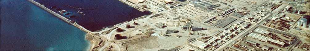
38 peak, critical state or residual? The value that will prevent the exceedance of the limit state. Caution about progressive loss of density or strength. So caution about >38º. Suggestion: The ULS design value of the shear strength should never be greater than a cautious (ie characteristic ) estimate of the critical state strength of the material. Interfaces between structure and ground (wall friction, sliding etc) use critical state value as characteristic value, and apply normal factors. Useful guidance in BS8002 ( withdrawn )
39 peak, critical state or residual? Critical state Useful guidance in BS8002 ( withdrawn )
40 The best GI is as many different tests as possible. Paul Mayne So we have to be able to consider results from different tests together. Some more definite than others. May conflict. 40
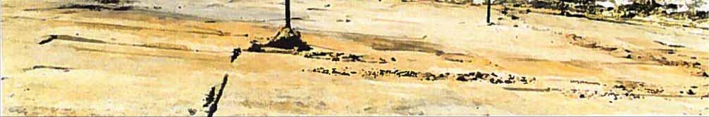
41 Data from more than one source Bored pile
42 Conflicting data The code drafters could not have known about this uncertainty
43 BP198.2 BP201.2 Eurocode 7 fundamental issues and some implications for users Safety format of EC7 Characteristic and design values of soil parameters EG11 - Lovisa Moritz, Sweden Design in situations dominated by water pressures The EQU limit state Numerical analysis for ULS design 43
44 BP198.2 BP201.2 Eurocode 7 fundamental issues and some implications for users Safety format of EC7 Characteristic and design values of soil parameters Design in situations dominated by water pressures The EQU limit state Numerical analysis for ULS design 44


45 Dubai Dry Dock BP184.14


46 Dubai Dry Dock BP Factors of safety?!?


47


48 Construction basin in Western Australia


49


50


51


52


53


54


55


56


57


58 Water has a way of seeping between any two theories!


59 Piping failure


60 60
61 General (1)P Where relevant, it shall be verified that the following limit states are not exceeded: loss of equilibrium of the structure or the ground, considered as a rigid body, in which the strengths of structural materials and the ground are insignificant in providing resistance (EQU); internal failure or excessive deformation of the structure or structural elements, including e.g. footings, piles or basement walls, in which the strength of structural materials is significant in providing resistance (STR); failure or excessive deformation of the ground, in which the strength of soil or rock is significant in providing resistance (GEO); loss of equilibrium of the structure or the ground due to uplift by water pressure (buoyancy) or other vertical actions (UPL); hydraulic heave, internal erosion and piping in the ground caused by hydraulic gradients (HYD). 61
P Where relevant, it shall be verified that the following limit states are not exceeded: loss of equilibrium of the structure or the ground, considered as a rigid body, in which the")
62 General (1)P Where relevant, it shall be verified that the following limit states are not exceeded: loss of equilibrium of the structure or the ground, considered as a rigid body, in which the strengths of structural materials and the ground are insignificant in providing resistance (EQU); a a internal failure or excessive deformation of the structure or structural elements, including W W e.g. footings, piles or basement walls, in which the strength of structural materials is M significant in providing resistance (STR); F1 F2 failure or excessive deformation of the ground, in which the strength of soil or rock is significant b in providing resistance (GEO); loss of equilibrium of the structure or the ground due to uplift by water pressure (buoyancy) or other vertical actions (UPL); hydraulic heave, internal erosion and piping in the ground caused by hydraulic gradients (HYD). 62
63 General (1)P Where relevant, it shall be verified that the following limit states are not exceeded: loss of equilibrium of the structure or the ground, considered as a rigid body, in which the strengths of structural materials and the ground are insignificant in providing resistance (EQU); internal failure or excessive deformation of the structure or structural elements, including e.g. footings, piles or basement walls, in which the strength of structural materials is significant in providing resistance (STR); F = 1.0, 1.35, 1.5 etc failure or excessive deformation of the ground, in which the strength of soil or rock is significant in providing resistance (GEO); F = 1.0, 1.35, 1.5 etc loss of equilibrium of the structure or the ground due to uplift by water pressure (buoyancy) or other vertical actions (UPL); F,dst = 1.0/1.1, F,stb = 0.9 hydraulic heave, internal erosion and piping in the ground caused by hydraulic gradients (HYD). F,dst = 1.35, F,stb =

64 64
65 (9)P Actions in which ground- and free-water forces predominate shall be identified for special consideration with regard to deformations, fissuring, variable permeability and erosion. NOTE Unfavourable (or destabilising) and favourable (or stabilising) permanent actions may in some situations be considered as coming from a single source. If they are considered so, a single partial factor may be applied to the sum of these actions or to the sum of their effects. 65


66 Geotechnical safety in relation to water pressures B. Simpson Arup Geotechnics, London, UK N. Vogt Technische Universität München, Zentrum Geotechnik, Munich, Germany A. J. van Seters Fugro GeoServices, The Netherlands 66


67 67
68 Geotechnical safety in relation to water pressures B. Simpson Arup Geotechnics, London, UK N. Vogt Technische Universität München, Zentrum Geotechnik, Munich, Germany A. J. van Seters Fugro GeoServices, The Netherlands Introduction Case histories of failures caused by water pressure Existing geotechnical codes and guidance documents Requirements of EC7 Some fundamental considerations Examples Recommendations 68

69 69
70 70
71 Need robustness Accommodate the worst water pressures Apply the single source principle Don t factor water density (?) Use of an offset in water level (?) Reduced factor on favourable weight (?) The star approach (?) A middle 2/3rds rule (?) Use engineering expertise 71

72 72
73 1m rise in water level multiplies BM by about 2.5 outside the range allowed by factors on the water pressure or water force. 73


74 U stb G;stb & G,dst 2. Buoyant weight 3. Factor water density 4. Water unfactored U dst 74


75 G;stb & G,dst 2. Buoyant weight 3. Factor water density 4. Water unfactored F variable F permanent 75
? At some point, equilibrium is not preserved. But the question is where?")
76 Should generally be avoided Use unfactored water pressures and forces? Don t factor density but factor pressures (AvS)? Don t factor pressures but factor forces (NV)? At some point, equilibrium is not preserved. But the question is where? The problems are less for DA1, but not removed. 76
77 h 77
78 n R k /W w n.rk/ww 2 1 (a) (b) (c) (d) (e) (f) n R k /W w n.rk/ww (c) (e) (d) (f) (b) (a) h/d h/d Number of piles required (normalised). (a) unfactored, (b) pile resistance factored, (c) G = 1.35 on water pressure, (d) water table adjusted, (e) UPL, h/d h/d 78


79 The possibility of a reduced factor on favourable weight, perhaps between 0.8 and 0.9 should be considered. 79
80 n R k /W w n.rk/ww 2 1 (a) (b) (c) (d) (e) (f) n R k /W w n.rk/ww (c) (e) (d) (f) (b) (a) h/d h/d Number of piles required (normalised). (a) unfactored, (b) pile resistance factored, (c) G = 1.35 on water pressure, (d) water table adjusted, (e) UPL, (f) G;fav = 0.8 on weight h/d h/d 80
 In some design situations, the application of partial factors to actions coming from or through the soil (such as earth or water pressures) could lead to design values which are unreasonable or")
81 EC (2) In some design situations, the application of partial factors to actions coming from or through the soil (such as earth or water pressures) could lead to design values which are unreasonable or even physically impossible. In these situations, the factors may be applied directly to the effects of actions derived from representative values of the actions. Apply only to structural bending moments etc, or more generally? 81
82 Depending on other factors, it might be necessary to enhance the loads derived from water pressure (or load effects such as an uplifting force), even when they are very certain. Problem in cases where it is directly equivalent to factoring water pressures 82
83 A middle 2/3rds rule could be considered. Effective resultant force must lie within the middle 2/3rds of the base. 83


84 84
85 Need robustness Accommodate the worst water pressures Apply the single source principle Don t factor water density (?) Use of an offset in water level (?) Reduced factor on favourable weight (?) The star approach (?) A middle 2/3rds rule (?) Use engineering expertise 85
86 Values of partial factors recommended in EN Annex A Combination 1 Apply factors, either to Design approach 1 Design approach 2 Design approach 3 Combination Combination Combination 2 - piles & anchors DA2 - Comb 1 DA2 - Slopes DA3 A1 M1 R1 A2 M2 R1 A2 M1 or M2 R4 A1 M1 R2 A1 M=R2 A1 A2 M2 R3 Actions Permanent unfav 1,35 1,35 1,35 1,35 Soil fav Variable unfav 1,5 1,3 1,3 1,5 1,5 1,5 1,3 water pressures (ugh!) tan ' 1,25 1,25 StructuraGeotech 1,25 Effective cohesion 1,25 1,25 actions actions 1,25 Undrained strength 1,4 1,4 or to structural action 1,4 Unconfined strength 1,4 1,4 1,4 Weight density effects such as Spread Bearing 1,4 footings Sliding 1,1 bending moments and Driven Base 1,3 1,1 piles Shaft (compression) 1,3 1,1 Total/combined 1,3 prop 1,1 forces (DA1-1*) Shaft in tension 1,25 1,6 1,15 1,1 Bored Base 1,25 1,6 1,1 piles Shaft (compression) 1,0 1,3 1,1 Total/combined 1,15 1,5 1,1 Shaft in tension 1,25 1,6 Combination 1,15 2 1,1 CFA Base 1,1 1,45 1,1 piles Shaft (compression) 1,0 1,3 1,1 Use the worst credible Total/combined 1,1 1,4 1,1 Shaft in tension 1,25 1,6 1,15 1,1 Anchors Temporary 1,1 1,1 water 1,1 pressures, Permanent 1,1 1,1 1,1 Retaining Bearing capacity unfactored. 1,4 walls Sliding resistance 1,1 Earth resistance 1,4 Slopes Earth resistance 1,1 indicates partial factor = 1.0 C:\BX\BX-C\EC7\[Factors.xls] 25-Nov-06 17:26 86


87 Geotechnical safety in relation to water pressures B. Simpson Arup Geotechnics, London, UK N. Vogt Technische Universität München, Zentrum Geotechnik, Munich, Germany A. J. van Seters Fugro GeoServices, The Netherlands 87
88 z u G S EC7 { (1)P} states: When considering a limit state of failure due to heave by seepage of water in the ground (HYD, see 10.3), it shall be verified, for every relevant soil column, that the design value of the destabilising total pore water pressure (u dst;d ) at the bottom of the column, or the design value of the seepage force (S dst;d ) in the column is less than or equal to the stabilising total vertical stress ( stb;d ) at the bottom of the column, or the submerged weight (G stb;d ) of the same column: u dst;d stb;d (2.9a) total stress (at the bottom of the column) S dst;d G stb;d (2.9b) effective weight (within the column) 88
 ground (HYD, see 10.")
89 z u G S Annex A of EC7 provides values for partial factors to be used for HYD, G;dst = 1.35 and G;stb = 0.9. But the code does not state what quantities are to be factored. Maybe: EC7 { (1)P} states: When considering a limit state of failure due to heave by G;dst seepage u dst;k of G;stb water stb;k in the (2.9a) ground (HYD, see 10.3), it shall be verified, for every and relevant soil column, that the design value of the destabilising total pore water pressure G;dst S dst;k (u dst;d G;stb ) at G stb;k the bottom (2.9b) of the column, or the design value of the seepage force (S dst;d ) in the column is less than or equal to the stabilising total vertical In stress this format, ( stb;d ) at the the factors bottom are of applied the column, to different or the quantities submerged in weight 2.9 a and b. (G stb;d ) of the same column: u dst;d stb;d (2.9a) total stress (at the bottom of the column) S dst;d G stb;d (2.9b) effective weight (within the column) 89
90 H=? 7m 1m 3m Uniform permeability 90
91 u dst;d stb;d (2.9a) total stress (at the bottom of the column) S dst;d G stb;d (2.9b) effective weight (within the column) Apply G;dst = 1.35 to: Apply G;stb = 0.9 to: H Pore water pressure u dst;k Total stress stb;k 2.78 Seepage force S dst;k Buoyant weight G stb;k 6.84 Excess pore pressure u dst;k - w z Buoyant density 6.84 Excess head (u dst;k - w z) / w Buoyant Orr, density T.L.L G;dst u dst;k G;stb stb;k (2.9a) 6.84 Model Solutions for Eurocode 7 Excess pore pressure or excess head Total Workshop density Examples. 6.1 G;dst S dst;k G;stb G stb;k (2.9b) Trinity College, Dublin. 91
92 u dst;d stb;d (2.9a) total stress (at the bottom of the column) S dst;d G stb;d (2.9b) effective weight (within the column) Apply G;dst = 1.35 to: Apply G;stb = 0.9 to: H Pore water pressure u dst;k Total stress stb;k 2.78 Seepage force S dst;k Buoyant weight G stb;k 6.84 Excess pore pressure u dst;k - w z Buoyant density 6.84 Excess head (u dst;k - w z) / w Buoyant density 6.84 Excess pore pressure or excess head Total density
93 BP198.2 BP201.2 Eurocode 7 fundamental issues and some implications for users Safety format of EC7 Characteristic and design values of soil parameters Design in situations dominated by water pressures EG9 Norbert Vogt, Germany The EQU limit state Numerical analysis for ULS design 93
94 BP198.2 BP201.2 Eurocode 7 fundamental issues and some implications for users Safety format of EC7 Characteristic and design values of soil parameters Design in situations dominated by water pressures The EQU limit state Numerical analysis for ULS design 94
95 95 Paper on the EQU problem
96 EN1990 Single source and EQU a a W W M F 1 F 2 b Note 3 : The characteristic values of all permanent actions from one source are multiplied by G,sup if the total resulting action effect is unfavourable and G,inf if the total resulting action effect is favourable. For example, all actions originating from the self weight of the structure may be considered as coming from one source ; this also applies if different materials are involved. 96
97 a a W W M F 1 F 2 b 97
98 What if EQU not balanced? How to involve material strength? W a a W Three views: 1. Material demand only calculated when design W s balanced. For a=5b M/Wa F/W M F 1 F 2 b 2. Nonsense! Must apply G = 1.35, , (tension) 3. Treat EQU as another load case. Check M, F 1, F 2 for G = 0.9, 1.1 OR G = 1.15, G a,k G b,k P k.stb a/2 b 98
99 Overturning on infinitely strong rock. b W Dry sand (loose) F Infinitely strong rock For finite strength, check Wx1.0; Fx1.35 (or material factor on tan of sand). Check ground and structure.? For infinite strength, check overturning for Wx0.9; Fx1.1? Less severe design loading because rock infinitely strong? Less severe loading for overturning than for sliding? Even the structure is not infinitely strong. So not a real problem? But no problem if EQU treated as another load case. 99
100 Soil strength also involved Q (1.5) 1 2 Homogeneous dry sand W (0.9 < 1.0) h Inclination of slip surface < d Inclination of slip surface > d d=0 Nobody wants EQU to rule. Could make a special rule to prevent EQU check.? Better to require the check in principle and arrange factors so that it will never be critical. 100
101 EN1997 UKNA Partial material factors reduced for EQU 101
102 BP198.2 BP201.2 Eurocode 7 fundamental issues and some implications for users Safety format of EC7 Characteristic and design values of soil parameters Design in situations dominated by water pressures The EQU limit state TC250 group including chair of SC7 Numerical analysis for ULS design 102
103 BP198.2 BP201.2 Eurocode 7 fundamental issues and some implications for users Safety format of EC7 Characteristic and design values of soil parameters Design in situations dominated by water pressures The EQU limit state Numerical analysis for ULS design 103
104 BP198.2 BP201.2 Eurocode 7 fundamental issues and some implications for users Safety format of EC7 Characteristic and design values of soil parameters Design in situations dominated by water pressures The EQU limit state Numerical analysis for ULS design What to factor and when to factor? 104
105 BP124-T2.14 BP124-A2.12 BP BP BP Partial factors recommended in EN Annex A (+UKNA) Values of partial factors recommended in EN Annex A (+ UKNA) Design approach 1 Design approach 2 Design approach 3 Combination Combination Combination 2 - piles & anchors DA2 - Comb 1 DA2 - Slopes DA3 A1 M1 R1 A2 M2 R1 A2 M1 or M2 R4 A1 M1 R2 A1 M=R2 A1 A2 M2 R3 Actions Permanent unfav 1,35 1,35 1,35 1,35 fav Variable unfav 1,5 1,3 1,3 1,5 1,5 1,5 1,3 Soil tan ' 1,25 1,25 StructuraGeotech 1,25 Effective cohesion 1,25 1,25 actions actions 1,25 Undrained strength 1,4 1,4 1,4 Unconfined strength 1,4 1,4 1,4 Weight density Spread Bearing 1,4 footings Sliding 1,1 Driven Base 1,3 1,1 piles Shaft (compression) 1,3 1,1 Total/combined 1,3 1,1 Shaft in tension 1,25 1,6 1,15 1,1 Bored Base 1,25 1,6 1,1 piles Shaft (compression) 1,0 1,3 1,1 Total/combined 1,15 1,5 1,1 Shaft in tension 1,25 1,6 1,15 1,1 CFA Base 1,1 1,45 1,1 piles Shaft (compression) 1,0 1,3 1,1 Total/combined 1,1 1,4 1,1 Shaft in tension 1,25 1,6 1,15 1,1 Anchors Temporary 1,1 1,1 1,1 Permanent Easy to factor 1,1 primary input 1,1 1,1 Retaining Bearing capacity 1,4 walls Sliding resistance material strengths and actions 1,1 Earth resistance 1,4 Slopes Earth resistance 1,1 Difficult to factor geotechnical resistances and action effects indicates partial factor = 1.0 C:\BX\BX-C\EC7\[Factors.xls] 25-Nov-06 17:26 105
106 Fundamental limit state requirement BP193.8 E d R d E{ F ; d X ; a d d } = E d R d = R{ F ; d X ; a d d } E{ F F rep ; X k / M ; a d } = E d R d = R{ F F rep ; X k / M ; a d } or E{ F F rep ; X k / M ; a d } = E d R d = R k / R = R n R (LRFD) or E E k = E d R d = R k / R so in total E E{ F F rep ; X k / M ; a d } = E d R d = R{ F F rep ; X k / M ; a d }/ R Reduce strength, increase the loads, and check equilibrium OR Find the remaining FOS? OR c- reduction 106
107 Pre-factored strength, or c- reduction? Max wall displacement 48mm Large displacement Max wall displacement 48mm xbcap5-dec11ab.sfd = 1.25 = = 1.25 = m M R;d BENDING MOMENT knm/m 107

108 Wrong failure mechanism? Max wall displacement 48mm Large displacement Max wall displacement 48mm xbcap5-dec11ab.sfd = 1.25 = There is no right failure mechanism Because failure isn t the right answer! EC7 is interested in proving success, not failure. Finding FOS useful for design refinement, but not for final verification. Plastic models of structural elements useful in ULS analysis.
109 Factoring advanced models, c, c u not explicit parameters eg Cam Clay, BRICK etc Change to Mohr-Coulomb for the factored calculation? If c = this is the factor on drained strength, however derived. Consider: is the model s drained strength more or less reliable than those used in conventional practice? eg the model might take good account of combinations of principal stresses, direction (anisotropy), stress level etc. Possibly modify factors in the light of this. 109
 than on effective stress parameters (eg 1.25 on c, tan ). 110")
110 Undrained strength in effective stress models Reliable computation of undrained strength from effective stress parameters is very difficult. EC7 generally requires a higher factor on undrained strength (eg 1.4 on c u ) than on effective stress parameters (eg 1.25 on c, tan ). 110
111 Undrained strength in effective stress models Reliable computation of undrained strength from effective stress parameters is very difficult. EC7 generally requires a higher factor on undrained strength (eg 1.4 on c u ) than on effective stress parameters (eg 1.25 on c, tan ). The drafters assumed that effective stress parameters would be used only for drained states. The higher factor (eg 1.4) was considered appropriate for characteristic values of c u based on measurement, which is generally more reliable than values computed from effective stress parameters. So it is unreasonable to adopt a lower value for the latter. 111
112 Time-dependent analysis Beyond EC7! 112
113 ULS for staged construction single propped excavation Compute using factored strength Compute using unfactored characteristic parameters parameters Compute using factored parameters Factor material strengths Initial state? Excavate to 5m wall cantilevering Initial state Excavate to 5m wall cantilevering Could be critical for wall bending moment Install prop at 4m depth Excavate to 10m No further factors on strut forces or BMs Install prop at 4m depth Excavate to 10m Apply factors on strut forces or BMs Could be critical for wall length, bending moment and prop force No further factors on strut forces or BMs 113
114 Staged construction FE with partial facotrs Compute using factored strength Compute using unfactored characteristic parameters parameters Compute using factored parameters Factor material strengths Better continuity and consistency? Initial state? Suits some software. Excavate to 5m wall cantilevering Only one definition of soil properties. Install prop at 4m depth But: conservatism at one stage might be unconservative at Excavate to 10m another. No further factors on strut forces or BMs Initial state Suits some software. Excavate to 5m Combines wall cantilevering SLS analysis Can be used with more Install advanced prop at 4m depth soil models Excavate to 10m Apply factors on strut forces or BMs Could be critical for wall bending moment Could factor soil strengths or take another approach Could be critical for wall length, bending moment and prop force No further factors on strut forces or BMs 114


115 Simpson, B and Hocombe, T (2010) Implications of modern design codes for earth retaining structures. Proc ER2010, ASCE Earth Retention Conference 3, Seattle, Aug Florence Rail Station 25m deep, 50m wide, 550m long Mezzanine level prop High groundwater level 115
116 Eurocode case study: High speed rail station, Florence, Italy 454m long, 52m wide and 27 to 32m deep 1.2 to 1.6m thick diaphragm walls Three levels of temporary strutting. 116
117 Eurocode case study: High speed rail station, Florence, Italy SLS analyzed as if London Clay using the BRICK model. Time dependent swelling and consolidation. Eurocode 7, DA1, Combinations 1 and 2 analysed using FE and Oasys FREW. 117


118 Eurocode case study: High speed rail station, Florence, Italy Eurocode 7 readily used with FE for this large project. Geotechnical and structural design readily coordinated. 118
119 BP BP BP BP124-T2.13 BP124-A2.11 Partial factors for DA1 UK National Annex BP Design approach 1 Combination Combination Combination 2 - piles & anchors A1 M1 R1 A2 M2 R1 A2 M1 or M2 R4 Actions Permanent unfav 1,35 fav Variable unfav 1,5 1,3 1,3 Soil tan ' 1,25 1,25 Effective cohesion 1,25 1,25 Undrained strength 1,4 1,4 Unconfined strength 1,4 1,4 Weight density Spread Bearing EC7 footings Sliding values Driven Base 1,7/1.5 1,3 piles Shaft (compression) 1.5/1.3 1,3 Total/combined 1.7/1.5 1,3 Shaft in tension 2.0/ Bored Base 2.0/1.7 1,6 piles Shaft (compression) 1.6/1.4 1,3 Total/combined 2.0/ Shaft in tension 2.0/ CFA Base As 1.45 piles Shaft (compression) for 1.3 Total/combined bored 1.4 Shaft in tension piles 1.6 Anchors Temporary 1,1 1,1 Permanent 1,1 1,1 Retaining Bearing capacity walls Sliding resistance Earth resistance Slopes Earth resistance indicates partial factor = 1.0 C:\BX\BX-C\EC7\[Factors.xls] 119
120 ULS for staged construction single propped excavation Compute using factored strength Compute using unfactored characteristic parameters parameters Compute using factored parameters Factor material strengths Initial state? Excavate to 5m wall cantilevering Initial state Excavate to 5m wall cantilevering Could be critical for wall bending moment Install prop at 4m depth Excavate to 10m No further factors on strut forces or BMs Install prop at 4m depth Excavate to 10m Apply factors on strut forces or BMs Could be critical for wall length, bending moment and prop force No further factors on strut forces or BMs 120
 C1 C1 C1 C2, factors all stages C2, factors all stages C2, factors all stages C2,factoring stages separately C2, factors all stages C2, factoring stages")
121 Florence Station comparison of bending moments 45 Prop and excavation levels Stage Level (m) ,000-4,000-2, ,000 4,000 6,000 8,000 Bending Moment (knm/m) C1 C1 C1 C2, factors all stages C2, factors all stages C2, factors all stages C2,factoring stages separately C2, factors all stages C2, factoring stages separately 121
122 BP198.2 BP201.2 Eurocode 7 fundamental issues and some implications for users Safety format of EC7 Characteristic and design values of soil parameters Design in situations dominated by water pressures The EQU limit state Numerical analysis for ULS design EG4 Andrew Lees - Cyprus 122
123 Concluding remarks Code-drafter s challenge: To standardise and regulate where it is sensible to do so, while encouraging maximum exploitation of engineering expertise. Characteristic values and water pressures: full use of human knowledge, sometimes guided but never governed by statistics. Partial factors: society s safety margin (and ours!). FEM the tool of the future code must not restrict. EC7 still evolving! 123
124 BP201.1 Nordic Geotechnical Meeting Copenhagen, May 2012 BP198.1 Eurocode 7 fundamental issues and some implications for users Brian Simpson, Arup Geotechnics Thanks for your attention 124
EN Eurocode 7. Section 8 Anchorages Section 9 Retaining structures. Brian Simpson Arup Geotechnics
 EUROCODES Background and Applications EN1997-1: Anchorages and Retaining structures Brussels, 18-20 February 2008 Dissemination of information workshop 1 EN 1997-1 Eurocode 7 Section 8 Anchorages Section
COMPARISON OF EC7 DESIGN APPROACHES FOR NUMERICAL ANALYSIS OF DEEP EXCAVATIONS
 S C I E N C E P A S S I O N T E C H N O L O G Y COMPARISON OF EC7 DESIGN APPROACHES FOR NUMERICAL ANALYSIS OF DEEP EXCAVATIONS Helmut F. Schweiger Computational Geotechnics Group Institute for Soil Mechanics
Geotechnical Engineering Software GEO5
 Geotechnical Engineering Software GEO5 GEO5 software suite is designed to solve various geotechnical problems. The easy -to -use suite consists of individual programs with an unified and user-friendly
Monitoring a Drilled Shaft Retaining Wall in Expansive Clay: Long-Term Performance in Response to Moisture Fluctuations
 1348 Brown, A.C., Dellinger, G., Helwa, A., El-Mohtar, C., Zornberg, J.G., and Gilbert, R.B. (2015). Monitoring a Drilled Shaft Retaining Wall in Expansive Clay: Long-Term Performance in Response to Moisture
AVOIDING EXCESSIVE DISPLACEMENTS: A NEW DESIGN APPROACH FOR RETAINING WALLS
 International Conference on Structural and Foundation Failures August 2-4, 4, Singapore AVOIDING EXCESSIVE DISPLACEMENTS: A NEW DESIGN APPROACH FOR RETAINING WALLS A. S. Osman and M.D. Bolton Department
Eurocode 7: Geotechnical design
 BRITISH STANDARD BS EN 1997-1:2004 Eurocode 7: Geotechnical design Part 1: General rules https://geotechnicaldesign.info/ec7p1.html The European Standard EN 1997-1:2004 has the status of a British Standard
Unit 48: Structural Behaviour and Detailing for Construction. Limit State Design
 2.1 Introduction Limit State Design Limit state design of an engineering structure must ensure that (1) under the worst loadings the structure is safe, and (2) during normal working conditions the deformation
Testing of ground anchorages for a deep excavation retaining system in Bucharest
 XV Danube - European Conference on Geotechnical Engineering (DECGE 2014) H. Brandl & D. Adam (eds.) 9-11 September 2014, Vienna, Austria Paper No. 176 Testing of ground anchorages for a deep excavation
Comparison of geotechnic softwares - Geo FEM, Plaxis, Z-Soil
 Comparison of geotechnic softwares - Geo FEM, Plaxis, Z-Soil Comparison du logiciel géotechnique Geo FEM, Plaxis, Z-Soil J. Pruška CTU in Prague FCE Department of Geotechnics, Prague, Czech Republic, Pruska@fsv.cvut.cz
Design Illustrations on the Use of Soil Nails to Upgrade Loose Fill Slopes
 Design Illustrations on the Use of Soil Nails to Upgrade Loose Fill Slopes Geotechnical Engineering Office and The Hong Kong Institution of Engineers (Geotechnical Division) November 2013 2 Disclaimer
PE Exam Review - Geotechnical
 PE Exam Review - Geotechnical Resources and Visual Aids Item Page I. Glossary... 11 II. Parameters... 9 III. Equations....11 IV. Tables, Charts & Diagrams... 14 1. Module 1 - Soil Classification... 14
Position Paper of. FEM Product Group Cranes and Lifting Equipment - Sub-Group Tower and harbor Cranes
 FÉDÉRATION EUROPÉENNE DE LA MANUTENTION Product Group Krane und Hebezeuge Cranes and Lifting Equipment Grues et ponts roulants et Appareils de levage February 2014 Position Paper of FEM Product Group Cranes
Downloaded from Downloaded from /1
 PURWANCHAL UNIVERSITY VI SEMESTER FINAL EXAMINATION-2003 LEVEL : B. E. (Civil) SUBJECT: BEG359CI, Foundation Engineering. Full Marks: 80 TIME: 03:00 hrs Pass marks: 32 Candidates are required to give their
Challenges in Design and Construction of Deep Excavation With Case Studies - KVMRT in KL Limestone
 Challenges in Design and Construction of Deep Excavation With Case Studies - KVMRT in KL Limestone Gue See Sew G&P Professionals Sdn Bhd www.gnpgroup.com.my 20 July 2016 CONTENTS INTRODUCTION SOIL PARAMETERS
Retaining Wall Design
 SIL 211 MEKANIKA TANAH Retaining Wall Design DR. IR. ERIZAL, MAGR DEPARTEMEN TEKNIK SIPIL DAN LINGKUNGAN FAKULTAS TEKNOLOGI PERTANIAN IPB 1 Conventional Retaining Walls Gravity Retaining Structures Stability
Licensing International Engineers into the Profession (LIEP)
") List and Description of Courses for approval of Equivalence in lieu of PEO s CEP Civil Engineering Course Descriptions (Revised Proposal) GROUP A 98-CIV -A1 Elementary Structural Analysis: Computation
List and Description of Courses for approval of Equivalence in lieu of PEO s CEP Civil Engineering Course Descriptions (Revised Proposal) GROUP A 98-CIV -A1 Elementary Structural Analysis: Computation
1.364 ADVANCED GEOTECHNICAL ENGINEERING HOMEWORK No. 5
 .364 ADVANCED GEOTECHNICAL ENGINEERING HOMEWORK No. Due: Friday December 2. This question concerns the stability of an open slope cutting that will be used to provide construction access for a 3.2m deep
EN REINFORCED MASONRY DESIGN EXAMPLE 1 (NOTE: THIS USES THE UK NATIONAL ANNEX NDP VALUES)
") 42.50 10.00 3.00 20.00 EN 1996-1-1 REINFORCED MASONRY DESIGN EXAMPLE 1 (NOTE: THIS USES THE UK NATIONAL ANNEX NDP VALUES) Reinforced Masonry - Reinforced Brickwork Stem Cantilever Pocket-Type Retaining
42.50 10.00 3.00 20.00 EN 1996-1-1 REINFORCED MASONRY DESIGN EXAMPLE 1 (NOTE: THIS USES THE UK NATIONAL ANNEX NDP VALUES) Reinforced Masonry - Reinforced Brickwork Stem Cantilever Pocket-Type Retaining
GEOTECHNICAL RESISTANCE FACTORS
 Chapter 9 GEOTECHNICAL RESISTANCE FACTORS Final SCDOT GEOTECHNICAL DESIGN MANUAL 9-i Table of Contents Section Page 9.1 Introduction... 9-1 9.2 Soil Properties... 9-2 9.3 Resistance Factors for LRFD Geotechnical
Single Piles and Pile Groups
 Single Piles and Pile Groups Under Lateral Loading 2nd Edition Lymon C. Reese Academic Chair Emeritus Department of Civil Engineering The University of Texas at Austin William Van Impe Full Professor of
Geoguide 6 The New Guide to Reinforced Fill Structure and Slope Design in Hong Kong
 Geoguide 6 The New Guide to Reinforced Fill Structure and Slope Design in Hong Kong Geotechnical Engineering Office Civil Engineering Department The Government of the Hong Kong Special Administrative Region
2. SAFETY VERIFICATIONS OF SHALLOW FOUNDATIONS Bearing capacity failure
 Seismic design of shallow foundations Bearing capacity of soil Pedro Miguel Sereno July 216 ABSTRACT Traditionally the verification on the bearing capacity of shallow foundation in a seismic situation
Temporary Structures. Excavations and Excavation Supports
 UNIVERSITY OF WASHINGTON DEPARTMENT OF CONSTRUCTION MANAGEMENT CM 420 TEMPORARY STRUCTURES Winter Quarter 2007 Professor Kamran M. Nemati Temporary Structures Excavations and Excavation Supports CM 420
Revision Nalcor Doc. No. MFA-SN-CD-0000-GT-DC C1 Date Page SLI Doc. No EC Dec-2013 ii DESIGN CRITERIA - GEOTECHNICAL
 SLI Doc. No. 505573-3000-40EC-0003 01 5-Dec-2013 ii TABLE OF CONTENTS Page No. 1 INTRODUCTION... 1 2 CREST ELEVATIONS... 2 2.1 Cofferdams... 2 2.2 North Spur... 3 3 STABILITY ANALYSIS LOADING CASES AND
Analysis of the stability of sheet pile walls using Discontinuity Layout Optimization
 Analysis of the stability of sheet pile walls using Discontinuity Layout Optimization S. D. Clarke, C. C. Smith & M. Gilbert The University of Sheffield, UK ABSTRACT: In this paper it is demonstrated that
 techie-touch.blogspot.com www.vidyarthiplus.com CE2305 FOUNDATION ENGINEERING 2 MARKS QUESTIONS & ANSWERS 16 MARKS QUESTIONS UNIT -1 1. What are components of total foundation settlement? elastic settlement,
Final PT Draft (Stage 34) Page 1. EUROPEAN STANDARD pren NORME EUROPÉENNE EUROPÄISCHE NORM. English version
 Page 1. EUROPEAN STANDARD pren NORME EUROPÉENNE EUROPÄISCHE NORM. English version") Final PT Draft (Stage 34) Page 1 EUROPEAN STANDARD pren 1998-5 NORME EUROPÉENNE EUROPÄISCHE NORM Doc CEN/TC250/SC8/N305 English version Eurocode 8: Design of structures for earthquake resistance Part 5:
Final PT Draft (Stage 34) Page 1 EUROPEAN STANDARD pren 1998-5 NORME EUROPÉENNE EUROPÄISCHE NORM Doc CEN/TC250/SC8/N305 English version Eurocode 8: Design of structures for earthquake resistance Part 5:
Lecture Retaining Wall Week 12
 Lecture Retaining Wall Week 12 Retaining walls which provide lateral support to earth fill embankment or any other form of material which they retain them in vertical position. These walls are also usually
NPTEL Course GROUND IMPROVEMENT USING MICROPILES
 Lecture 22 NPTEL Course GROUND IMPROVEMENT USING MICROPILES Prof. G L Sivakumar Babu Department of Civil Engineering Indian Institute of Science Bangalore 560012 Email: gls@civil.iisc.ernet.in Contents
ESECMASE - SHEAR TEST METHOD FOR MASONRY WALLS WITH REALISTIC BOUNDARY CONDITIONS
 ESECMASE - SHEAR TEST METHOD FOR MASONRY WALLS WITH REALISTIC BOUNDARY CONDITIONS E. FEHLING Professor of Civil Engineering Institute of Structural Engineering Chair of Structural Concrete University of
Modelling of a pile row in a 2D plane strain FE-analysis
 Numerical Methods in Geotechnical Engineering Hicks, Brinkgreve & Rohe (Eds) 2014 Taylor & Francis Group, London, 978-1-138-00146-6 Modelling of a pile row in a 2D plane strain FE-analysis J.J.M. Sluis,
Marina Bay Sands Hotel Arch 631 Kayla Brittany Maria Michelle
 Marina Bay Sands Hotel Arch 631 Kayla Brittany Maria Michelle Overall Information Location: Singapore Date of Completion: 2010 Cost: $5.7 billion Architect: Moshe Safdie Executive Architect: Aedas, Pte
Bearing Capacity of Geosynthetic Reinforced Foundation Beds on Compressible Clay
 3 r d International Conference on New Developments in Soil Mechanics and Geotechnical Engineering, Bearing Capacity of Geosynthetic Reinforced Foundation Beds on Compressible Clay K. Rajyalakshmi, Lecturer,
Interpretation of Danish Chalk Parameters Applicable to Foundation Design
 NGM 2016 Reykjavik Proceedings of the 17 th Nordic Geotechnical Meeting Challenges in Nordic Geotechnic 25 th 28 th of May Interpretation of Danish Chalk Parameters Applicable to Foundation Design L. Kellezi
[Kouravand Bardpareh* et al., 5(6): July, 2016] ISSN: IC Value: 3.00 Impact Factor: 4.116
![[Kouravand Bardpareh* et al., 5(6): July, 2016] ISSN: IC Value: 3.00 Impact Factor: 4.116](/thumbs/75/71557032.jpg "[Kouravand Bardpareh* et al., 5(6): July, 2016] ISSN: IC Value: 3.00 Impact Factor: 4.116") IJESRT INTERNATIONAL JOURNAL OF ENGINEERING SCIENCES & RESEARCH TECHNOLOGY STUDY ON HORIZONTAL DISPLACEMENT OF RESTRAINED EXCAVATION WALLS BY CANTILEVER RETAINING WALL Siavash Kouravand Bardpareh *1, Ashkan
IJESRT INTERNATIONAL JOURNAL OF ENGINEERING SCIENCES & RESEARCH TECHNOLOGY STUDY ON HORIZONTAL DISPLACEMENT OF RESTRAINED EXCAVATION WALLS BY CANTILEVER RETAINING WALL Siavash Kouravand Bardpareh *1, Ashkan
EN1990 Eurocode Basis of structural design
 Proceedings of ICE Civil Engineering 144 November 2001 Pages 8 13 Paper 12624 Keywords codes of practice & standards; design methods & aids; strength and testing of materials Haig Gulvanessian is director
Optimum Static Analysis of Retaining Wall with & without shelf /Shelve at different level using finite Element analysis
 Optimum Static Analysis of Retaining Wall with & without shelf /Shelve at different level using finite Element analysis Prof. Dr. D.N.Shinde(Guide) 1, Mr.Rohan R. Watve(Student) 2 Civil Department,PVPIT
Prof. Dipl.-Ing. H. Quick Ingenieure und Geologen GmbH provides geotechnical engineering services e. g. for high-rise buildings in Germany and abroad.
 Prof. Dipl.-Ing. Hubert Quick City Hall of Dubai, March, 7 th, 2005 o Prof. Dipl.-Ing. H. Quick Ingenieure und Geologen GmbH provides geotechnical engineering services e. g. for high-rise buildings in
Case study of deep excavation in existing underground structure of three-story basement and diaphragm wall
 Geotechnical Aspects of Underground Construction in Soft Ground Yoo, Park, Kim & Ban (Eds) 2014 Korean Geotechnical Society, Seoul, Korea, ISBN 978-1-138-02700-8 Case study of deep excavation in existing
UNDERPINNING A CRANE FOUNDATION
 UNDERPINNING A CRANE FOUNDATION Donald R. McMahon, P.E., McMahon & Mann Consulting Engineers, P.C., Buffalo, New York, USA Andrew J. Nichols, P.E., McMahon & Mann Consulting Engineers, P.C., Buffalo, New
BACKGROUND: SUBSURFACE CONDITIONS:
 2 BACKGROUND: The planned project consists of a prefabricated modular apartment building with underground parking, located on the site bounded by Dexter Avenue N. to the east, multi-story residential/commercial
Possible solution to past CM exam question. Question 2 July New city centre office block. by Rajavel Inbarajan
 Possible solution to past CM exam question Question 2 July 2015 New city centre office block by Rajavel Inbarajan The information provided should be seen as an interpretation of the brief and a possible
MSE WALLS CASE STUDIES. by John G. Delphia, P.E. TxDOT Bridge Division Geotechnical Branch
 MSE WALLS CASE STUDIES by John G. Delphia, P.E. TxDOT Bridge Division Geotechnical Branch COMMON RETAINING WALL TYPES CONCRETE BLOCK MSE TEMPORARY EARTH SPREAD FOOTING Gabions Drilled Shaft Soil Nail Tiedback
Case Studies on Soil Nailed Retaining Systems for Deep Excavations
 Indian Geotechnical Conference 2010, GEOtrendz December 16 18, 2010 IGS Mumbai Chapter & IIT Bombay Case Studies on Soil Nailed Retaining Systems for Deep Excavations Murthy, B.R. Srinivasa Professor e-mail:
2. LIMIT STATE DESIGN
 2. LIMIT STATE DESIGN 2.1 Introduction to Limit State Design A Civil Engineering Designer has to ensure that the structures and facilities he designs are (i) fit for their purpose (ii) safe and (iii) economical
Weekly Safety Talks: Excavation & Trenching Application
 Weekly Safety Talks: Excavation & Trenching Application Review when we need to go into a trench. Ask can we do it any other way? Review soil types in the area and prevention methods preferred. Discuss
INNOVATIVE SLOPE STABILISATION BY USING ISCHEBECK TITAN SOIL NAILS
 Dipl.-Wirt.Ing. Oliver Freudenreich Friedr. Ischebeck GmbH phone: ++49 2333 8305-0 Loher Str. 31 79 fax: ++49 2333 8305-55 e-mail: freudenreich@ischebeck.de D-58256 Ennepetal www.ischebeck.com INNOVATIVE
339. Massarsch, K.R and Fellenius, B.H., Ground vibrations from pile and sheet pile driving. Part 1 Building Damage. Proceedings of the DFI-
 339. Massarsch, K.R and Fellenius, B.H., 2014. Ground vibrations from pile and sheet pile driving. Part 1 Building Damage. Proceedings of the DFI- EFFC International Conference on Piling and Deep Foundations,
LOAD CAPACITY OF AUGER DISPLACEMENT PILES
 International Conference on Ground Improvement and Ground Control (ICGI 2012), 30 Oct. 2 Nov. 2012, University of Wollongong, Australia B. Indraratna, C. Rujikiatkamjorn and J S Vinod (editors) LOAD CAPACITY
Topic: Site Formation
 Topic: Site Formation Presentation prepared by Raymond Wong February 2006 Purpose of site formation is to prepare a piece of land in order to: Accommodate building/s or other facilities which will be placed
Effective Stress Design For Floodwalls on Deep Foundations
 Effective Stress Design For Floodwalls on Deep Foundations Glen Bellew, PE Geotechnical Engineer USACE-Kansas City 23 April 2015 Contributors James Mehnert, PE USACE-Kansas City Paul Axtell, PE, D.GE Dan
EPS in CIVIL ENGINEERING APLLICATIONS: Product properties and performance requirements connected
 EPS in CIVIL ENGINEERING APLLICATIONS: Product properties and performance requirements connected ABSTRACT Since decades expanded polystyrene (EPS) is successfully applied as light weight fill for roads
CPT based foundation engineering D-FOUNDATIONS
 CPT based foundation engineering D-FOUNDATIONS CPT based foundation engineering D-FOUNDATIONS General In the 1930s, Deltares (formerly known as GeoDelft) started the development of the Cone Penetration
LIGHTWEIGHT FILL DESIGN GUIDANCE
 Preferred Design Procedure LIGHTWEIGHT FILL The Federal Highway Administration (FHWA) and National Cooperative Highway Research Program (NCHRP) have two documents for this technology that contain design
DS/EN DK NA:2013
 National Annex to Eurocode 6: Design of masonry structures - Part 1-1: General rules for reinforced and unreinforced masonry structures Foreword This national annex (NA) is a revision and compilation of
Structural Analyses of Segmental Lining Coupled Beam and Spring Analyses Versus 3D-FEM Calculations with Shell Elements
 Structural Analyses of Segmental Lining Coupled Beam and Spring Analyses Versus 3D-FEM Calculations with Shell Elements C. Klappers, F. Grübl, B. Ostermeier PSP Consulting Engineers for Tunnelling and
Partial Factors of Safety
 APPENDIX A Partial Factors of Safety A.I Introduction The capacity of single piles in axial compression should provide an adequate safety factor against failure due to insufficient soil-pile interface
Ohio Department of Transportation Division of Production Management Office of Geotechnical Engineering. Geotechnical Bulletin
 Ohio Department of Transportation Division of Production Management Office of Geotechnical Engineering Geotechnical Bulletin GB 2 SPECIAL BENCHING AND SIDEHILL EMBANKMENT FILLS Geotechnical Bulletin GB2
Soil Mechanics Lateral Earth Pressures page Lateral Earth Pressures in case of inclined ground surface or friction at wall-ground interface
 Soil Mechanics Lateral Earth Pressures page 9 7.6 Lateral Earth Pressures in case of inclined ground surface or friction at wall-ground interface By now, we have considered the wall as perfectly smooth
CIVIL ENGINEERING. Subject Code: CE. Course Structure. Engineering Mathematics. Ordinary Differential Equation (ODE)
") CIVIL ENGINEERING Subject Code: CE Course Structure Sections/Units Section A Unit 2 Unit 3 Unit 4 Unit 5 Unit 6 Section B Unit 2 Unit 3 Unit 4 Unit 5 Unit 6 Section C Unit 2 Section D Topics Engineering
CIVIL ENGINEERING Subject Code: CE Course Structure Sections/Units Section A Unit 2 Unit 3 Unit 4 Unit 5 Unit 6 Section B Unit 2 Unit 3 Unit 4 Unit 5 Unit 6 Section C Unit 2 Section D Topics Engineering
Chapter 14 Lateral Earth Pressure
 Page 14 1 Chapter 14 Lateral Earth Pressure 1. Which of the following is not a retaining structure? (a) Retaining wall (b) Basement wall (c) Raft (d) Bulkhead 2. When a retaining structure does not move
Strength reduction factors for foundations and earthquake load combinations including overstrength factors
 Strength reduction factors for foundations and earthquake load combinations including overstrength factors S.J Palmer Tonkin & Taylor Ltd, Wellington, New Zealand 2013 NZSEE Conference ABSTRACT: Clause
DESIGNING AND CONSTRUCTION OF T-WALL RETAINING WALL SYSTEM
 Istanbul Bridge Conference August 11-13, 2014 Istanbul, Turkey DESIGNING AND CONSTRUCTION OF T-WALL RETAINING WALL SYSTEM T. C. NEEL and K.BOZKURT ABSTRACT This work shall consist of the design, manufacture
WEEK 13 Soil Behaviour at Very Large Strains
 WEEK 13 Soil Behaviour at Very Large Strains 19. Residual strength Starting from soil behaviour at very small strains (less than 0.001%), now we have come to that at very large strains, where the strength
Example of the Unified Design procedure for use in the September 8, 2014, short course on in Brazil
 Introduction Example of the Unified Design procedure for use in the September 8, 2014, short course on in Brazil The Unified Design procedure involves two main steps. The first is verifying that the loads
Requirements for Foundations on Liquefiable Sites
 Requirements for Foundations on Liquefiable Sites Robert Bachman, S.E. R. E. Bachman Consulting Structural Engineers Laguna Niguel, CA 1 Issue Team and ASCE 7 Contributing Members Evolved and Improved
Jet Grouting to Increase Lateral Resistance of Pile Group in Soft Clay
 GROUND MODIFICATION, PROBLEM SOILS, AND GEO-SUPPORT 265 Jet Grouting to Increase Lateral Resistance of Pile Group in Soft Clay Kyle M. Rollins 1, Matthew E. Adsero 2, and Dan A. Brown 3 1 Prof. Civil &
GeoEng2000 An International Conference on Geotechnical & Geological Engineering
 GeoEng2000 An International Conference on Geotechnical & Geological Engineering 19-24 November 2000 Melbourne Exhibition and Convention Centre Melbourne, Australia Barrettes : A versatile foundation for
Combined Pile Foundation System for a Residential Complex
 Combined Pile Foundation System for a Residential Complex Alvin K.M. Lam, Geotechnical Engineer, Ove Arup & Partners Hong Kong Limited, Hong Kong, China; email: alvin.lam@arup.com Daman D.M. Lee, Civil
Seismic Design of a Slope Stabilization Work Using Piles and Tendons
 6 th International Conference on Earthquake Geotechnical Engineering 1-4 November 2015 Christchurch, New Zealand Seismic Design of a Slope Stabilization Work Using Piles and Tendons H. Sanchez Lizarraga
Seismic assessment of horizontal cylindrical reservoirs
 Seismic assessment of horizontal cylindrical reservoirs Christos Baltas 1, Pierino Lestuzzi 1, 2, Martin G. Koller 1 1 2 Résonance Ingénieurs-Conseils SA 21 rue Jacques Grosselin, 1227 Carouge, Suisse
CIVIL BREADTH Exam Specifications
 NCEES Principles and Practice of Engineering Examination CIVIL BREADTH and STRUCTURAL DEPTH Exam Specifications Effective Beginning with the April 2015 Examinations The civil exam is a breadth and depth
Comparison of Eurocode 8 and Turkish Earthquake Code 2007 for Residential RC Buildings in Cyprus
 Comparison of Eurocode 8 and Turkish Earthquake Code 2007 for Residential RC Buildings in Cyprus I. SAFKAN University College London, UK SUMMARY The Cyprus Island is located at seismic zone and many destructive
Numerical Analysis of a Novel Piling Framed Retaining Wall System
 The 12 th International Conference of International Association for Computer Methods and Advances in Geomechanics (IACMAG) 1-6 October, 2008 Goa, India Numerical Analysis of a Novel Piling Framed Retaining
Numerical Modeling of Slab-On-Grade Foundations
 Numerical Modeling of Slab-On-Grade Foundations M. D. Fredlund 1, J. R. Stianson 2, D. G. Fredlund 3, H. Vu 4, and R. C. Thode 5 1 SoilVision Systems Ltd., 2109 McKinnon Ave S., Saskatoon, SK S7J 1N3;
Construction Planning, Equipment, and Methods PILES AND PILE-DRIVING EQUIPMENT
 CHAPTER Construction Planning, Equipment, and Methods PILES AND PILE-DRIVING EQUIPMENT Sixth Edition A. J. Clark School of Engineering Department of Civil and Environmental Engineering 19 By Dr. Ibrahim
PILE SETTLEMENT ZONES ABOVE AND AROUND TUNNELLING OPERATIONS
 PILE SETTLEMENT ZONES ABOVE AND AROUND TUNNELLING OPERATIONS H.G. Poulos Coffey Geosciences Pty Ltd. ABSTRACT This paper describes briefly the method of analysis of the response of a pile to tunnelling-induced
Design of Deep Foundations for Slope Stabilization
 Design of Deep Foundations for Slope Stabilization J. Erik Loehr, Ph.D., P.E. University of Missouri Annual Kansas City Geotechnical Conference Overland Park, Kansas April 23, 215 Stability analysis for
Chapter A-15. CID-MO Structural Analysis
 Kansas Citys, Missouri and Kansas Flood Risk Management Feasibility Study Engineering Appendix to the Final Feasibility Study Chapter A-15 CID-MO Structural Analysis Chapter A-15 CID-MO Structural Analysis
Geotechnical standards in Hong Kong
 Geotechnical standards in Hong Kong ACECC Workshop on Harmonization of Design Codes in Asian Region November 4, 2006, Taipei, Taiwan L. M. Mak President, Hong Kong Geotechnical Society (This paper has
ENGINEERING AND CONSTRUCTION BULLETIN
 ENGINEERING AND CONSTRUCTION BULLETIN No. 2017-2 Issuing Office: CECW-CE Issued: 27 Jan 17 Expires: 27 Jan 19 SUBJECT: Revision and Clarification of EM 1110-2-2100 and EM 1110-2-2502. CATEGORY: Guidance.
USE OF THE OBSERVATIONAL APPROACH FOR EMBANKMENT CONSTRUCTION ON ORGANIC SOIL DEPOSITS IN SRI LANKA
 USE OF THE OBSERVATIONAL APPROACH FOR EMBANKMENT CONSTRUCTION ON ORGANIC SOIL DEPOSITS IN SRI LANKA R.P.D.S.Premalal, B.Sc.Undergraduate, Department of Civil Engineering, University of Moratuwa (email:
PIANC UK Seminar Design Developments and Specification for Steel. Duncan Nicholson Arup Fellow 9/3/17 ICE London
 PIANC UK Seminar Design Developments and Specification for Steel Duncan Nicholson Arup Fellow 9/3/17 ICE London Contents 1. Design Issues 2. SPERWall Edition 3 (2016) 1. Steel Sheet Piles (Section 14)
Offshore pile acceptance using dynamic pile monitoring
 Offshore pile acceptance using dynamic pile monitoring Webster, S. & Givet, R. GRL Engineers, Inc. Charlotte, NC, USA Griffith, A. Saudi Aramco, Dhahran, Saudi Arabia ABSTRACT: Dynamic pile monitoring
Schedule of Accreditation issued by United Kingdom Accreditation Service 2 Pine Trees, Chertsey Lane, Staines-upon-Thames, TW18 3HR, UK
 Schedule of ccreditation United Kingdom ccreditation Service ccredited to skern Road Carcroft Doncaster South Yorkshire DN6 8DG Contact: Jason Charles Tel: +44 (0)1302 723456 Fax: +44 (0)1302 725240 E-Mail:
Northport Berth 3 design and construction monitoring
 Proc. 18 th NZGS Geotechnical Symposium on Soil-Structure Interaction. Ed. CY Chin, Auckland Lucy Coe, Nicola Ridgley, Do Van Toan Beca Infrastructure Limited, Auckland, NZ Keywords: retaining wall, deflections,
Serviceability limit state design in geogrid reinforced walls and slopes
 Loughborough University Institutional Repository Serviceability limit state design in geogrid reinforced walls and slopes This item was submitted to Loughborough University's Institutional Repository by
SPECIFICATIONS FOR PRECAST MODULAR BLOCK RETAINING WALL SYSTEM (revised 5/8/7)
") Page 1 of 7 STONE STRONG SYSTEMS SPECIFICATIONS FOR PRECAST MODULAR BLOCK RETAINING WALL SYSTEM (revised 5/8/7) PART 1: GENERAL 1.01 Description A. Work includes furnishing and installing precast modular
Page 1 of 7 STONE STRONG SYSTEMS SPECIFICATIONS FOR PRECAST MODULAR BLOCK RETAINING WALL SYSTEM (revised 5/8/7) PART 1: GENERAL 1.01 Description A. Work includes furnishing and installing precast modular
Influence of unloading soil modulus on horizontal deformation of diaphragm wall
 Influence of unloading soil modulus on horizontal deformation of diaphragm wall Hoang Viet NGUYEN 1 and Thi Dieu Chinh LUU 2 1 Lecturer, Soil Mechanics and Foundation Department, National University of
Types of Foundations
 Shallow Foundations Types of Foundations Foundations can be classified to two major categories: Shallow. Deep. 1 Introduction If the soil stratum is suitable for supporting the structural loads from the
Using EPS Buffers for Diaphragm Walls
 Using EPS Buffers for Diaphragm Walls Beshoy M. FAKHRY1, Salem A. AZZAM2, and Sherif S. ABDELSALAM1 1 Graduate Student, the British University in Egypt, beshoy115377@bue.edu.eg 2 Teaching Assistant, the
Immersed Tunnels. Richard Lunniss and Jonathan Baber. CRC Press. Taylor & Francis Group. Taylor & Francis Group, A SPON BOOK
 Immersed Tunnels Richard Lunniss and Jonathan Baber CRC Press Taylor & Francis Group Boca Raton London New York CRC Press is an imprint of the Taylor & Francis Group, an informa business A SPON BOOK Contents
4D grouting pressure model of a bored tunnel in 3D Tunnel
 4D grouting pressure model of a bored tunnel in 3D Tunnel F.J.M. Hoefsloot & A. Verweij, Fugro Ingenieursbureau B.V., The Netherlands INTRODUCTION For some ten years TBM-techniques have been used to construct
Properties in Shear. Figure 7c. Figure 7b. Figure 7a
 Properties in Shear Shear stress plays important role in failure of ductile materials as they resist to normal stress by undergoing large plastic deformations, but actually fail by rupturing under shear
Numerical Analysis for High-rise Building Foundation and Further Investigations on Piled Raft Design
 ctbuh.org/papers Title: Authors: Subject: Keyword: Numerical Analysis for High-rise Building Foundation and Further Investigations on Piled Raft Design Jinoh Won, Deputy General Manager, Samsung C&T Corporation
4D grouting pressure model PLAXIS
 4D grouting pressure model PLAXIS F.J.M. Hoefsloot & A. Verweij Fugro Ingenieursbureau B.V., Leidschendam, The Netherlands ABSTRACT: Bored tunnels are about to be constructed in the urban areas of Amsterdam
NEW PERFORMANCE CRITERIA FOR FRESH TREMIE CONCRETE
 NEW PERFORMANCE CRITERIA FOR FRESH TREMIE CONCRETE Karsten Beckhaus (1), Martin Larisch (2), Habib Alehossein (3,4) (1) BAUER Spezialtiefbau GmbH, Deutschland (2) Keller Australia Pty Ltd, Australia (3)
CE 6012 Ground Improvement Techniques Question Bank
 CE 6012 Ground Improvement Techniques Question Bank Unit I INTRODUCTION Role of ground improvement in foundation engineering - methods of ground improvement Geotechnical problems in alluvial, laterite