Effective Stress Design For Floodwalls on Deep Foundations
|
|
|
- Molly Harmon
- 6 years ago
- Views:
Transcription


1 Effective Stress Design For Floodwalls on Deep Foundations Glen Bellew, PE Geotechnical Engineer USACE-Kansas City 23 April 2015 Contributors James Mehnert, PE USACE-Kansas City Paul Axtell, PE, D.GE Dan Brown and Associates US Army Corps of Engineers
2 Outline Project Background Load Cases Considered Seepage Analysis Foundation Analysis Observed Performance 1993 Flood Existing Wall Stability Alternatives Considered and Selected Design Verification Load Test Major Findings/Lessons Learned Construction Photographs


3 Project Location Fairfax Jersey Creek Levee Missouri River BPU Floodwall Fairfax-Jersey Creek Levee Unit Kansas River
 BPU Floodwall Critical Infrastructure (Power Plant, water treatment) 1400 ft Major Manufacturing (GM")
4 Project and Leveed Area Details Levee/Flood Wall constructed 1940 s by USACE Highly Developed Area (~$3.3 billion) BPU Floodwall Critical Infrastructure (Power Plant, water treatment) 1400 ft Major Manufacturing (GM Plant) Kansas River
5 Existing Floodwall and Subsurface Conditions ~16 ft ~20 ft CL/ML g=119 pcf ~20 ft Sheet Pile ~80 ft Sand g=116 pcf Fluted, Tapered Steel Pipe Piles
6 Non Critical Load Case Short Term Flood Typical infrastructure analysis, buildings, bridges, etc. No time for blanket seepage Pre-flood s and stress history control S u Sand, f, g ~Horizontal Seepage
7 Critical Load Case Long Term Flood Analysis specific to water retention structures ~Vertical Seepage, reduces s Effective Stress Controls behavior, f, g flood Sand, f, g ~Horizontal Seepage
8 Effective Stress Design Process Establish seepage conditions (effective stress) Determine Ultimate Axial pile capacity Lateral response of pile group (often controls design) Calibrate analysis to observed performance
9 Seepage Analysis Criteria Dh i=dh/z z Historically criteria has focused on preventing rupture/heave of topstratum by limiting vertical gradients to less than critical gradient (i c = g /g w ). Original design (1940 s) design ensured H < z. Current requirements are FS >1.6
10 Seepage Analysis Methodology calculating h Blanket Theory (EM ) Simple geometric inputs (great for simple stratigraphy) Decades of performance to verify adequacy of method Spreadsheet solutions quick to perform

11 Seepage Analysis Methodology calculating h Finite Element Modeling (next EM ) Unlimited complexity in geometry and boundary conditions Modeling quirks can lead to unrealistic results for a novice user In situ permeabilities, boundary conditions, model extent User interface improving, but can be time consuming to set up Use when complexity warrants
12 Pile Design Methodology Axial Capacity Overall Drained Strength Parameters Effective State of stress reasonably assumed for flood conditions EM Criteria - FS min = 1.7 Side Resistance b method Nordlund for driven, tapered piles Tip resistance Bearing Capacity Factors
13 Pile Design Methodology Lateral Response Typical to use Ensoft s Lpile and/or Group Software p-y curves by soil type (drained sand, undrained clay) Unit weight Friction angle p-y modulus (k p-y ) Group effects auto p-mult. Criteria Max D = 1.5
14 Effective Stress Lateral Response - Ensoft Design Case Long Term Flood P-y curves not available for drained conditions in cohesive soil Use Sand Curves with appropriate f Cannot input U>hydrostatic directly Reduce g of blanket by g flood = g -ig w also accounts for artesian sand p-y modulus (k p-y ) estimated based on soil type/strength Loose-Medium Sand or Soft-Medium Clay Group requires an estimate of the axial load response (auto or input)
15 Performance Observations ~3 ft ~45 Day duration Seepage some reports of concentrated seeps with possible pin boils, no major boil activity Structural Performance no performance observations noted Documentation limited
16 Calibrate with Back Analysis of 1993 Flood? i avg = 0.7 RESULTS Seepage: FS~1.3 Pile Capacity: FS = 1.5 Pile Structural >failure Deflections 1.5 max g flood = 13 pcf f = 29 deg k p-y = 50 pci P-y curve API Sand g ' = 53.6 pcf f = 36 deg k p-y = 60 pci P-y curve API Sand
17 Probability of Failure (%) No failure predicted, none observed 45 Probability of Failure Brittle Response Maximum Possible Load Maximum Historical Load Loading Example fragility curve, not BPU floodwall
18 Existing Floodwall Analysis w/ TOW i avg = 0.83 FS i = 1.1 g flood = 9 pcf f = 29 deg k p-y = 50 pci P-y curve API Sand g ' = 53.6 pcf f = 36 deg k p-y = 60 pci P-y curve API Sand
19 Existing Floodwall Results w/ TOW Axial FS <1 Deflections >>1.5 Floodwall modification needed

")
20 Design/Site Constraints Landside The Good: Well Defined Site (<100 spaced borings) Laboratory Data (consol, R-bar, class.) Foundation Load Test during construction Riverside The Bad: Constrained ROW Maintain similar pile spacing No driven/vibrated elements Drilled Shafts Difficult Design Case (low effective stresses) Lateral Deflections a major design constraint (limit to 1.5 under extreme load)
21 Modification Alternatives 1. Cut off and Found. New Foundation $ g flood = 53.6 pcf f = 29 deg k p-y = 50 pci P-y curve API Sand Full Depth Cut-Off (~100 feet) $$$
22 Modification Alternatives 2. RW and Found. New Foundation $$ Relief Wells $ g flood = 25.4 pcf f = 29 deg k p-y = 50 pci P-y curve API Sand
23 Selected Modification Alternative RW and Found. New Foundation Cap Extension and Buttresses Structural Modification 1 st Contract 24 Steel Casing, HP 12x74 Relief Wells 2 nd contract
24 Load Test Planning and Considerations ASTM D 1143 loading procedures B Maintained Load Test and C Loading in Excess of Maintained Test (2 hr holds) Estimate drained response (need extended static holds 2 24-hr holds lateral and 1 24-hr hold axial) Production Style shafts for combined/lateral ~40 kip lateral and ~35 kip axial design loads Groundwater conditions and stress states from load test to design condition are very different (link with s )
25 Load Test Goals Variables in Axial Analysis f g Interface friction, d Reasonably Known for Design Case Nice to Validate with Load Test Variables in Lateral/Group Analysis f g Sand p-y curve K p-y Axial response curves Reasonably Known for Design Case Need to Validate with Load Test Nice to have from Axial Load Test Combined Load Test structural performance of hybrid shaft

26 Load Test Overview Axial Figures and photos courtesy Dan Brown and Associates.

27 Load Test Overview Lateral/Combined Figures and photos courtesy Dan Brown and Associates.

28 Axial Load Test Results 2 hr 130 kip 24 hr hold Axial Results Data courtesy Dan Brown and Associates.
29 head Lateral Load Test Results Lateral Results 120 kip 24 hr hold 60 kip 24 hr hold 2 hr Data courtesy Dan Brown and Associates.
30 Load Test Results Applicability to Design Case Drained conditions reasonably approximated during load test Back analyze load test responses to calibrate lateral model Need state of stress during lateral load test (including suction) effective stress model applicable to both design and load test conditions (Lpile is frictional - f, g ) K p-y will be over-estimated in back analysis of load test if suction is ignored. Design Water Surface Normal Ground Water
31 Load Test Effective Stress - Soil Suction Soil Water Characteristic Curve (SWCC) ASTM D 6836 Relates in situ volumetric water content to soil suction Suction profile with depth = effective stress profile g unsat > g
32 Shear Strength with Soil Suction Estimating shear strength with soil suction Khalili and Khabazz (1998) t s = c + s v tanf + Cytanf Where, t s = unsaturated shear strength c = drained cohesion (zero) s v = gravity stress y = matrix suction f = drained friction angle C = fitting parameter Can t input t s directly into a frictional L-Pile model
33 Considering Soil Suction in LPile Calculate a Modified Friction Angle to account for soil suction s v tanf + Cytanf = s v tanf m where f m = modified friction angle Solve for f m for blanket to get an applicable friction angle that is f(suction). Assumes f m that results in appropriate t s is reasonable to account for suction in a frictional model. Material f f m Blanket Sand Necessary because Ensoft doesn t have ability to directly account for U.

 Axial Response curves Develop normalized (to ultimate capacity)")
34 Axial Load Test Interpretation Soil/Casing interface friction angle Assumed f=d, measured 1.1f=d (conservatism or incomplete drainage?) Axial Response curves Develop normalized (to ultimate capacity) side resistance and tip resistance response curves for use in Group
35 Lateral Load Test Back Analysis w/ normal GWT and suction Calibrate K p-y for verification of design Assumes K p-y same for all states of stress for effective stress analysis Solve for this g gravity = 115 pcf f m = 39 deg k p-y = Variable P-y curve API Sand Verify this is appropriate g gravity = 53.6 pcf f = 36 deg k p-y = Variable P-y curve API Sand
36 Lateral Load Test Back Analysis Results Load Test Calibrated Analysis Working Load 30 kip 60 kip Original Calibrated Material K p-y K p-y Blanket Sand Conservative original estimate?
37 Major Findings and Lessons Learned Load Test Drained conditions approximated during 2 hr load steps A complete test with 24 hr minimum holds next time? Sand p-y curves approximate drained behavior of fine grained soil Modified friction angle can account for soil suction in Lpile Load and temperature variations can be problematic during extended static holds Consider direct U dissipation measurement adjacent to shaft Design Can reduce FS min if load test performed during design K p-y was reasonably estimated prior to load test Ensoft programs account for effective stress design Accounting for U directly would be an improvement FLAC or finite element could improve understanding
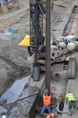

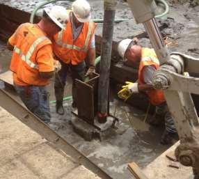

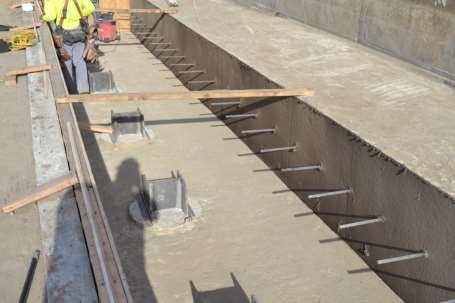
38 Construction Shaft Installation
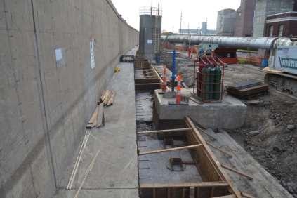
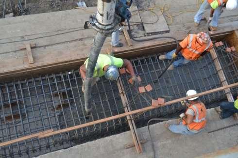
39 Construction Cap Extension


40 Construction Completed Wall Modification

41 Questions?
HURRICANE SANDY LIMITED REEVALUATION REPORT UNION BEACH, NEW JERSEY DRAFT ENGINEERING APPENDIX SUB APPENDIX B-2 FLOODWALL PILE ANALYSES EAST WALLS
 HURRICANE SANDY LIMITED REEVALUATION REPORT UNION BEACH, NEW JERSEY DRAFT ENGINEERING APPENDIX SUB APPENDIX B-2 FLOODWALL PILE ANALYSES EAST WALLS Revised March 2015 Preliminary Flood Wall Pile Analysis
Chapter A-15. CID-MO Structural Analysis
 Kansas Citys, Missouri and Kansas Flood Risk Management Feasibility Study Engineering Appendix to the Final Feasibility Study Chapter A-15 CID-MO Structural Analysis Chapter A-15 CID-MO Structural Analysis
Chapter A-9 GEOTECHNICAL ANALYSIS NORTH KANSAS CITY - LOWER (HARLEM AREA)
") Kansas Citys, Missouri and Kansas Flood Damage Reduction Feasibility Study (Section 216 Review of Completed Civil Works Projects) Engineering Appendix to the Interim Feasibility Report Chapter A-9 GEOTECHNICAL
Kansas Citys, Missouri and Kansas Flood Damage Reduction Feasibility Study (Section 216 Review of Completed Civil Works Projects) Engineering Appendix to the Interim Feasibility Report Chapter A-9 GEOTECHNICAL
ENGINEERING REPORT STRUCTURAL STABILITY ANALYSIS FLOODWALLS. HOUSATONIC RIVER and NAUGATUCK RIVER FLOOD PROTECTION PROJECTS SECTION 1
 ENGINEERING REPORT STRUCTURAL STABILITY ANALYSIS FLOODWALLS HOUSATONIC RIVER and NAUGATUCK RIVER FLOOD PROTECTION PROJECTS SECTION 1 ANSONIA and DERBY, CONNECTICUT December 2010 MMI #1560-119 and #3118-03
Lateral Loads on Micropiles. Thomas Richards Nicholson Construction Company
 Lateral Loads on Micropiles Thomas Richards Nicholson Construction Company Micropile Names Micropile ( DFI & FHWA) = Pin Pile SM ( Nicholson) = Minipile (previously used by Hayward Baker and used in UK)
Nonlinear Modeling of Dynamic Soil-Structure Interaction: A Practitioner s Viewpoint
 Nonlinear Modeling of Dynamic Soil-Structure Interaction: A Practitioner s Viewpoint By (Arul) K. Arulmoli Earth Mechanics, Inc. Fountain Valley, California Workshop on Nonlinear Modeling of Geotechnical
Chapter A-10 GEOTECHNICAL ANALYSIS NORTH KANSAS CITY - LOWER (NATIONAL STARCH AREA)
") Kansas Citys, Missouri and Kansas Flood Damage Reduction Feasibility Study (Section 216 Review of Completed Civil Works Projects) Engineering Appendix to the Interim Feasibility Report Chapter A-10 GEOTECHNICAL
Kansas Citys, Missouri and Kansas Flood Damage Reduction Feasibility Study (Section 216 Review of Completed Civil Works Projects) Engineering Appendix to the Interim Feasibility Report Chapter A-10 GEOTECHNICAL
SETTLEMENTS DUE TO TUNNEL CONSTRUCTION
 5 SETTLEMENTS DUE TO TUNNEL CONSTRUCTION In this tutorial the construction of a shield tunnel in medium soft soil and the influence on a pile foundation is considered. A shield tunnel is constructed by
Three Dimensional Soil-Structure-Interaction Analysis of a Flood Wall Under Full-Scale Load Test
 Missouri University of Science and Technology Scholars' Mine International Conference on Case Histories in Geotechnical Engineering (2013) - Seventh International Conference on Case Histories in Geotechnical
COPYRIGHTED MATERIAL. Contents PART ONE: THEORY...1. Preface to the Third Edition xiii. About the Authors xv. Acknowledgements xvii
 Preface to the Third Edition xiii About the Authors xv Acknowledgements xvii Contents PART ONE: THEORY...1 1. Groundwater in Construction...3 1.1 Groundwater in the Hydrologic Cycle 3 1.2 Origins of Dewatering
Case History: Value Engineering of Driven H-Piles for Slope Stability on the Missouri River
 DEEP FOUNDATIONS 207 Case History: Value Engineering of Driven H-Piles for Slope Stability on the Missouri River W. Robert Thompson, III, 1 M.ASCE, P.E., Jeffrey R. Hill, 2 M.ASCE, P.E., and J. Erik Loehr,
Chapter A-13 STRUCTURAL ANALYSIS ARGENTINE RAISE
 Kansas Citys, Missouri and Kansas Flood Damage Reduction Feasibility Study (Section 216 Review of Completed Civil Works Projects) Engineering Appendix to the Interim Feasibility Report Chapter A-13 STRUCTURAL
FB-MULTIPIER: P-Y MODEL VALIDATION
 FB-MULTIPIER: P-Y MODEL VALIDATION FB-MultiPier V4.19 vs. LPILE V6.0.15 July 2014 Jae Chung, Ph.D. Anand Patil, E.I. Henry Bollmann, P.E. Bridge Software Institute 1 EXECUTIVE SUMMARY This report summarizes
Upon speaking with the representatives with Technical Foundations as well as Walder Foundations, it was determined that:
 As part of our analyses, we have considered the design and construction of the cantilever retaining wall that will be located along the north side of Lucks Lane, between Falling Creek and Gladstone Glen
Client Project Job # Wall Loc. SBWall Report deg 120 pcf 950 psf deg 0.0 ft. 6.0 ft 6.0 ft 2.0 ft. W16x50.
 SBWall Report Soils Data Soil Friction Angle, phi Soil Unit Weight, gamma Soil Surcharge (uniform), qs Passive Resistance, FSp Passive Wedge Width, PW*B Backfill Slope Angle, beta Ignore Passive Resistance,
Overburden Effect on the Axial Resistance of Instrumented CFA Piles. Knoxville, TN 37922, ph ,
 703 Overburden Effect on the Axial Resistance of Instrumented CFA Piles Timothy C. Siegel 1, M. ASCE, P.E., G.E., D.GE and Peter Faust 2 1 Principal Engineer, Dan Brown and Associates, PC, 1808 Northshore
Chapter A-8 GEOTECHNICAL ANALYSIS FAIRFAX-JERSEY CREEK (JERSEY CREEK SHEET PILE WALL)
") Kansas Citys, Missouri and Kansas Flood Damage Reduction Feasibility Study (Section 216 Review of Completed Civil Works Projects) Engineering Appendix to the Interim Feasibility Report Chapter A-8 GEOTECHNICAL
Kansas Citys, Missouri and Kansas Flood Damage Reduction Feasibility Study (Section 216 Review of Completed Civil Works Projects) Engineering Appendix to the Interim Feasibility Report Chapter A-8 GEOTECHNICAL
Distribution Restriction Statement
 DEPARTMENT OF THE ARMY U.S. Army Corps of Engineers CECW-EG Washington, DC 20314-1000 Technical Letter No. 1110-2-555 30 November 1997 Engineering and Design DESIGN GUIDANCE ON LEVEES Distribution Restriction
Design of Deep Foundations for Slope Stabilization
 Design of Deep Foundations for Slope Stabilization J. Erik Loehr, Ph.D., P.E. University of Missouri Annual Kansas City Geotechnical Conference Overland Park, Kansas April 23, 215 Stability analysis for
Outline of Presentation. Behavior of Laterally Loaded Piles in A Mechanically Stabilized Earth (MSE) Wall
 Wall") Behavior of Laterally Loaded Piles in A Mechanically Stabilized Earth (MSE) Wall Jie Han, Ph.D., PE, F.ASCE Glenn L. Parker Professor of Geotechnical Engineering The University of Kansas, USA Outline of
Behavior of Laterally Loaded Piles in A Mechanically Stabilized Earth (MSE) Wall Jie Han, Ph.D., PE, F.ASCE Glenn L. Parker Professor of Geotechnical Engineering The University of Kansas, USA Outline of
STGEC Pre-Bid Load Testing for the Mobile River Bridge and Bayway Public Private Partnership (P3) Project
 Project") STGEC 2018 Reducing Pre-Bid Load Testing for the Mobile River Bridge and Bayway Public Private Partnership (P3) Project Sam Sternberg III, P.E. W. Robert Thompson III, P.E., D.GE / Sam Sternberg III, P.E.
STGEC 2018 Reducing Pre-Bid Load Testing for the Mobile River Bridge and Bayway Public Private Partnership (P3) Project Sam Sternberg III, P.E. W. Robert Thompson III, P.E., D.GE / Sam Sternberg III, P.E.
twenty six concrete construction: foundation design ELEMENTS OF ARCHITECTURAL STRUCTURES: FORM, BEHAVIOR, AND DESIGN DR. ANNE NICHOLS SPRING 2013
 ELEMENTS OF ARCHITECTURAL STRUCTURES: FORM, BEHAVIOR, AND DESIGN DR. ANNE NICHOLS SPRING 2013 lecture twenty six concrete construction: www.tamu.edu foundation design Foundations 1 Foundation the engineered
GEOTECHNICAL INVESTIGATION PROPOSED OUTFALL LOCATION CITY OF MORGAN S POINT DRAINAGE HARRIS COUNTY, TEXAS REPORT NO
 GEOTECHNICAL INVESTIGATION PROPOSED OUTFALL LOCATION CITY OF MORGAN S POINT DRAINAGE HARRIS COUNTY, TEXAS REPORT NO. 1140198001 Reported to: SIRRUS ENGINEERS, INC. Houston, Texas Submitted by: GEOTEST
Regulation 18 August 2009 NO Operations and Maintenance LEVEE ENCROACHMENT STANDARDS AND PROCEDURES
 CENWP-EC DEPARTMENT OF THE ARMY PDR 30-2-5 Portland District, Corps of Engineers (Draft) P.O. Box 2946 Portland, Oregon 97208 Regulation 8 August 2009 NO. 30-2-5 Operations and Maintenance LEVEE ENCROACHMENT
Evaluation of PDA Data to Identify Pile Issues Presented at Annual KC Specialty Seminar January 9, 2015
 Evaluation of PDA Data to Identify Pile Issues Presented at Annual KC Specialty Seminar January 9, 2015 Presentation Topics Overview of PDA data collection Case histories for how PDA testing reduced the
Chapter A-14 CID-KS STRUCTURAL ANALYSIS
 Kansas Citys, Missouri and Kansas Flood Risk Management Study to the Final Feasibility Report Chapter A-14 CID-KS STRUCTURAL ANALYSIS Chapter A-14 CID-KS Structural Analysis Table of Contents A-14.1 Overview...
Pile foundations Introduction
 Engineering manual No. 12 Updated: 06/2018 Pile foundations Introduction Program: Pile, Pile CPT, Pile Group The objective of this engineering manual is to explain the practical use of programs for the
NPTEL Course GROUND IMPROVEMENT USING MICROPILES
 Lecture 22 NPTEL Course GROUND IMPROVEMENT USING MICROPILES Prof. G L Sivakumar Babu Department of Civil Engineering Indian Institute of Science Bangalore 560012 Email: gls@civil.iisc.ernet.in Contents
Estimation of in-situ water content, void ratio, dry unit weight and porosity using CPT for saturated sands
 Barounis, N. & Philpot, J. (217) Estimation of in-situ water content, void ratio, dry unit weight and porosity using CPT for saturated sands Proc. 2 th NZGS Geotechnical Symposium. Eds. GJ Alexander &
Compaction and Jet Grouting
 Compaction and Jet Grouting Alan Ringen, PE Senior Vice President Breakthroughs in Tunneling Short Course August 16, 2017 Grouting Principles Geotechnical Grouting: The injection of pumpable fluid materials
Diaphragm wall with tieback supports (English units)
") Diaphragm wall with tieback supports (English units) Deep Excavation LLC Software program: DeepEX 2015 Document version: 1.0 December 16, 2014 www.deepexcavation.com Deep Excavation LLC 1 A. Project description
Diaphragm wall with tieback supports (English units) Deep Excavation LLC Software program: DeepEX 2015 Document version: 1.0 December 16, 2014 www.deepexcavation.com Deep Excavation LLC 1 A. Project description
LADOTD DRIVEN PILE DESIGN & VERIFICATION. Jesse G Rauser, PE USING LRFD
 LADOTD DRIVEN PILE DESIGN & VERIFICATION Jesse G Rauser, PE USING LRFD OBJECTIVES Not all of our policies, guidelines, and SOP s are in the same location Answer commonly asked questions about LADOTD pile
Code No: RR Set No. 1
 Code No: RR320101 Set No. 1 III B.Tech Supplimentary Examinations, Aug/Sep 2008 GEOTECHNICAL ENGINEERING (Civil Engineering) Time: 3 hours Max Marks: 80 Answer any FIVE Questions All Questions carry equal
Challenges of Offshore Geotechnical Engineering
 Challenges of Offshore Geotechnical Engineering OCE 582 - Seabed Geotechnics Professor Kate Moran presented by Ursula Hebinck Overview Content of Paper recent developments in offshore site investigation
Slope Stabilization using Drilled Shafts: Design and Long-Term Monitoring
 Slope Stabilization using Drilled Shafts: Design and Long-Term Monitoring Jamal Nusairat, Ph.D., P.E. E.L. Robinson Engineering of Ohio Co. & Izzaldin Almohd, Ph.D., P.E. Huesker Synthetic GmbH 8/4/2010
Brooks/Cole Thomson LearningiM. Fundamentals of Geotechnical Engineering. Braja M. Das. California State University, Sacramento
 Fundamentals of Geotechnical Engineering Braja M. Das California State University, Sacramento Brooks/Cole Thomson LearningiM Australia Canada Mexico Singapore Spain United Kingdom United States CHAPTER
Analysis of Four Load Tests on Augered Cast-in-Place Piles in the Texas Gulf Coast Soils Raghu Dass, PE, Woodward Vogt, PE, and Frank Ong, PE
 Analysis of Four Load Tests on Augered Cast-in-Place Piles in the Texas Gulf Coast Soils Raghu Dass, PE, Woodward Vogt, PE, and Frank Ong, PE Presented By: Raghu N. Dass, Ph. D., P.E. TSI Laboratories,
twenty four foundations and retaining walls Foundation Structural vs. Foundation Design Structural vs. Foundation Design
 ALIED ARCHITECTURAL STRUCTURES: STRUCTURAL ANALYSIS AND SYSTEMS DR. ANNE NICHOLS SRING 2018 lecture twenty four Foundation the engineered interface between the earth and the structure it supports that
SESSION-5C. Honolulu Rail Transit Project: Drilled Shaft Design Considerations and Challenges
 SESSION-5C Honolulu Rail Transit Project: Drilled Shaft Design Considerations and Challenges Presented By: Ahilan Selladurai, P.E., S.E Ahmad Abdel-Karim, Ph.D., P.E OUTLINE Project Introduction Shaft
CHAPTER 11: WALLS.
 CHAPTER 11: WALLS MODULAR BLOCK WALL (DRY CAST) Rather than being pre-approved as systems, the components of Modular block walls (dry cast) are pre-approved separately. The approved MBW components are
Chapter A-12 STRUCTURAL ANALYSIS EXISTING CONDITIONS
 Kansas Citys, Missouri and Kansas Flood Damage Reduction Feasibility Study (Section 216 Review of Completed Civil Works Projects) Engineering Appendix to the Interim Feasibility Report Chapter A-12 STRUCTURAL
twenty seven concrete construction: foundation design Foundation Structural vs. Foundation Design Structural vs. Foundation Design
 ARCHITECTURAL STRUCTURES: FORM, BEHAVIOR, AND DESIGN DR. ANNE NICHOLS SRING 2017 lecture twenty seven Foundation the engineered interface between the earth and the structure it supports that transmits
Determination of Design Infiltration Rates for the Sizing of Infiltration based Green Infrastructure Facilities
 Determination of Design Infiltration Rates for the Sizing of Infiltration based Green Infrastructure Facilities 1 Introduction This document, developed by the San Francisco Public Utilities Commission
CHAPTER 1 INTRODUCTION
 CHAPTER 1 INTRODUCTION 1.1 BACKGROUND Bridges and buildings are often supported on deep foundations. These foundations consist of groups of piles coupled together by concrete pile caps. These pile caps,
Monitoring a Drilled Shaft Retaining Wall in Expansive Clay: Long-Term Performance in Response to Moisture Fluctuations
 1348 Brown, A.C., Dellinger, G., Helwa, A., El-Mohtar, C., Zornberg, J.G., and Gilbert, R.B. (2015). Monitoring a Drilled Shaft Retaining Wall in Expansive Clay: Long-Term Performance in Response to Moisture
T-Wall Design Procedure (05 May 2008)
") 3.4.3.1 HPS T-Wall Design Procedure Description This design method evaluates the improvement in global stability by including the allowable shear and axial force contributions from the foundation piles
3.4.3.1 HPS T-Wall Design Procedure Description This design method evaluates the improvement in global stability by including the allowable shear and axial force contributions from the foundation piles
1.364 ADVANCED GEOTECHNICAL ENGINEERING HOMEWORK No. 5
 .364 ADVANCED GEOTECHNICAL ENGINEERING HOMEWORK No. Due: Friday December 2. This question concerns the stability of an open slope cutting that will be used to provide construction access for a 3.2m deep
PROJECT INFORMATION...
 TABLE OF CONTENTS Page No. PROJECT INFORMATION... 1 PROJECT AUTHORIZATION... 1 PROJECT DESCRIPTION... 1 PURPOSE AND SCOPE OF SERVICES... 1 SITE AND SUBSURFACE CONDITIONS... 3 SITE LOCATION AND DESCRIPTION...
THE PENNSYLVANIA STATE UNIVERSITY SCHREYER HONORS COLLEGE DEPARTMENT OF CIVIL AND ENVIRONMENTAL ENGINEERING
 THE PENNSYLVANIA STATE UNIVERSITY SCHREYER HONORS COLLEGE DEPARTMENT OF CIVIL AND ENVIRONMENTAL ENGINEERING LATERAL LOADING OF BATTERED PILES WITH RESPECT TO FOOTING SIZE VINCENT JOHN DEROSA Spring 2010
MSE WALLS CASE STUDIES. by John G. Delphia, P.E. TxDOT Bridge Division Geotechnical Branch
 MSE WALLS CASE STUDIES by John G. Delphia, P.E. TxDOT Bridge Division Geotechnical Branch COMMON RETAINING WALL TYPES CONCRETE BLOCK MSE TEMPORARY EARTH SPREAD FOOTING Gabions Drilled Shaft Soil Nail Tiedback
Utah State University
 Utah State University GIS in Water Resources CEE 6440 Dr. David Tarboton Underseepage Analysis in levees using GIS Prepared by Lourdes Polanco December, 2012 Introduction Levees are embankments designed
GEOTECHNICAL RESISTANCE FACTORS
 Chapter 9 GEOTECHNICAL RESISTANCE FACTORS Final SCDOT GEOTECHNICAL DESIGN MANUAL 9-i Table of Contents Section Page 9.1 Introduction... 9-1 9.2 Soil Properties... 9-2 9.3 Resistance Factors for LRFD Geotechnical
Single Piles and Pile Groups
 Single Piles and Pile Groups Under Lateral Loading 2nd Edition Lymon C. Reese Academic Chair Emeritus Department of Civil Engineering The University of Texas at Austin William Van Impe Full Professor of
On-site determination of pile capacity Distribution of pile load between the shaft and tip, and Detection of possible pile.
 Pile Load Test Pile foundation can be constructed depending on the stiffness of subsurface soil and ground water conditions and using a variety of construction techniques. The most common techniques are
PE Exam Review - Geotechnical
 PE Exam Review - Geotechnical Resources and Visual Aids Item Page I. Glossary... 11 II. Parameters... 9 III. Equations....11 IV. Tables, Charts & Diagrams... 14 1. Module 1 - Soil Classification... 14
Jet Grouting to Increase Lateral Resistance of Pile Group in Soft Clay
 GROUND MODIFICATION, PROBLEM SOILS, AND GEO-SUPPORT 265 Jet Grouting to Increase Lateral Resistance of Pile Group in Soft Clay Kyle M. Rollins 1, Matthew E. Adsero 2, and Dan A. Brown 3 1 Prof. Civil &
Pump Station Excavation
 Pump Station Excavation SPONSORED BY THE KIEWIT CORPORATION A capstone project for the The Department of Civil & Environmental Engineering in The Ira A. Fulton College of Engineering and Technology Brigham
ADDENDUM NO. 1. PROJECT NAME: Bostic Pelt Road NRCS Drainage Improvements PRI PROJECT NO: Wakulla Co ITB#
 ADDENDUM NO. 1 DATE: January 22, 214 TO: Prospective Bidders via individual e-mails FROM: Alan Wise, P.E. PROJECT NAME: Bostic Pelt Road NRCS Drainage Improvements PRI PROJECT NO: 23.15 ---- Wakulla Co
INITIAL SAFETY FACTOR ASSESSMENT EXISTING CCR IMPOUNDMENTS CCR Rule Section (e)
") INITIAL SAFETY FACTOR ASSESSMENT EXISTING CCR IMPOUNDMENTS CCR Rule Section 257.73(e) ASBURY POWER PLANT 21133 Uphill Lane Asbury, Missouri 64832 October 17, 2016 EMPIRE DISTRICT ELECTRIC COMPANY Prepared
INITIAL SAFETY FACTOR ASSESSMENT EXISTING CCR IMPOUNDMENTS CCR Rule Section 257.73(e) ASBURY POWER PLANT 21133 Uphill Lane Asbury, Missouri 64832 October 17, 2016 EMPIRE DISTRICT ELECTRIC COMPANY Prepared
Pore-Water Pressure Definition for a Levee Stability Analysis
 Pore-Water Pressure Definition for a Levee Stability Analysis GEO-SLOPE International Ltd. www.geo-slope.com 1200, 700-6th Ave SW, Calgary, AB, Canada T2P 0T8 Main: +1 403 269 2002 Fax: +1 888 463 2239
Steven Dapp, Ph.D., P.E. Steven Dapp, Ph.D., P.E. Dan Brown and Associates
 LA Transportation Conference: 10 Jan 2011 Drilled Shaft Foundations For Two Mississippi River Bridges in Louisiana Dan Brown and Associates Projects John James Audubon Bridge, St. Francisville New Construction
PDPI 2015 STATIC ANALYSIS LATERALLY LOADED PILE DESIGN. Chapter 9
 PDPI 2015 STATIC ANALYSIS LATERALLY LOADED PILE DESIGN Chapter 9 Lateral Capacity of Single Piles Potential sources of lateral loads include vehicle acceleration & braking, wind loads, wave loading, debris
U.S. ARMY CORPS OF ENGINEERS NEW ORLEANS DISTRICT
 U.S. ARMY CORPS OF ENGINEERS NEW ORLEANS DISTRICT Lock Replacement Project Cellular Cofferdam Feasibility Study GEOTECHNICAL ADDENDUM DESIGN REPORT 18 November 16 (Intentionally left blank) i TABLE OF
FUGRO CONSULTANTS, INC.
 FUGRO CONSULTANTS, INC. Report No. 4.112193-3 Revision No. 3, May 14, 215 Lockwood, Andrews & Newnam, Inc. 2925 Briarpark Drive, Suite 4 Houston, Texas 7742-372 61 Hillcroft (7781) P.O. Box 741 Houston,
Ground Modification Applications for Bio-Fuel Plants Raymond J. Franz, P.E. Roselle, IL
 Geotechnics and Supplying Future Energy Needs: Ground Modification Applications for Bio-Fuel Plants Raymond J. Franz, P.E. Roselle, IL Bio-Fuel Facilities Current and future energy needs demand consideration
Ardaman & Associates, Inc. Geotechnical, Environmental and Materials Consultants
 SUBSURFACE SOIL EXPLORATION ANALYSIS AND RECOMMENDATIONS PROPOSED WEIRS AT STATIONS 130+00 AND 16+00 DRAINAGE IMPROVEMENTS TO THE FOUR CORNERS MSBU HENDRY COUNTY, FLORIDA Ardaman & Associates, Inc. Geotechnical,
Bi-Directional Static Load Testing of Driven Piles
 Bi-Directional Static Load Testing of Driven Piles Paul J. Bullock, PhD Fugro Consultants Inc. Loadtest Bi-Directional Osterberg Cell Testing Specialized jack in pile uses bearing to mobilize side shear
Deep Foundations By. J. Paul Guyer, P.E., R.A. PDHLibrary Course No PDH HOURS
 Deep Foundations By J. Paul Guyer, P.E., R.A. PDHLibrary Course No 0010051 3 PDH HOURS An Introduction to Deep Foundations Guyer Partners 44240 Clubhouse Drive El Macero, CA 95618 (530) 758-6637 jpguyer@pacbell.net
Our Tour Stops. A Foundation Engineering gtrip down the Mississippi River. Dan Brown, P.E. Dan Brown and Associates 9/6/2010.
 A Foundation Engineering gtrip down the Mississippi River Dan Brown, P.E. Dan Brown and Associates Our Tour Stops I 35W Minneapolis US U.S. 61 Bridge, Hastings, MN New Mississippi River Bridge (I 70),
Coal Combustion Facility Assessment Report. October 20, 2010
 Coal Combustion Facility Assessment Report October 20, 2010 Introduction Stantec Consulting Services Inc. North American Consulting Firm 10,000 Engineers, Geologists, Architects, Scientists and Technicians
CHAPTER 23 PILES TABLE OF CONTENTS TABLE OF CONTENTS. 23.TOC Table of Contents... 30Jan Introduction... 30Jan2018
 CHAPTER 23 TABLE OF CONTENTS FILE NO. TITLE DATE TABLE OF CONTENTS 23.TOC Table of Contents... 30Jan2018 23.00 Introduction... 30Jan2018 DESIGN GUIDE FOR LATERALLY UNSUPPORTED 23.01-1 Notes and Definitions...
Investigation and Remediation for Existing 300 foot Tall Communication Towers. Presented at Annual Kansas City Geotechnical Conference April 25, 2013
 Investigation and Remediation for Existing 300 foot Tall Communication Towers Presented at Annual Kansas City Geotechnical Conference April 25, 2013 Presentation Topics Objective of Investigation Methodology
Attachment I-15: Reviews
 Attachment I-15: Reviews Attachment I-15 Agency Technical Review of Phase 2 and Phase 3 Documents January 2010 & August 2010 Attachment I-15, pg 1 ProjNet: Registered User Page 1 of 18 Comment Report:
TECHNICAL MEMORANDUM
 TECHNICAL MEMORANDUM SOIL SAMPLING, TESTING AND LOGGING ULOP GEOTECHNICAL EVALUATION STAR BEND SETBACK LEVEE Sutter County, California Prepared by: BLACKBURN CONSULTING 2491 Boatman Avenue West Sacramento,
Modules for Graduate Certificate in Geotechnical Engineering
 Modules for Graduate Certificate in Geotechnical Engineering * SkillsFuture credit (available for Singapore Citizens, subject to approval) ^ SkillsFuture Singapore (SSG) subsidy available for eligible
A Case Study: Foundation Design in Liquefiable Site
 RESEARCH ARTICLE OPEN ACCESS A Case Study: Foundation Design in Liquefiable Site Tahar Ayadat* *(Department of Civil Engineering, College of Engineering, PMU University, P.O. Box 1664, Al-Khobar, 31952,
Effectiveness of Compacted Fill and Rammed Aggregate Piers for Increasing Lateral Resistance of Pile Foundations
 Brigham Young University BYU ScholarsArchive All Theses and Dissertations 2010-11-09 Effectiveness of Compacted Fill and Rammed Aggregate Piers for Increasing Lateral Resistance of Pile Foundations Nathan
RS 3 A New 3D Program for Geotechnical Analysis
 RS 3 A New 3D Program for Geotechnical Analysis Rocscience is announcing the upcoming release of a brand new software program for 3-dimensional analysis and design of geotechnical structures RS 3 a general
Report of CCR Rule Stability Analyses AEP Clifty Creek Power Plant Boiler Slag Pond Dam and Landfill Runoff Collection Pond
 Report of CCR Rule Stability Analyses AEP Clifty Creek Power Plant Boiler Slag Pond Dam and Landfill Runoff Collection Pond Madison, Jefferson County, Indiana Prepared for: American Electric Power Columbus,
Axially Loaded Behavior of Driven PC Piles
 Axially Loaded Behavior of Driven PC Piles Shih-Tsung Hsu Associate Professor, Department of Construction Engineering, Chaoyang University of Technology, E-mail address: sthsu@cyut.edu.tw Abstract. To
TABLE OF CONTENTS. 1. Circular Sections Noncircular Sections...25
 EXECUTIVE SUMMARY This report summarizes comparisons between FB-MultiPier and LPILE, in which soil lateral resistance and pile/shaft response are numerically computed using p-y models. 2 TABLE OF CONTENTS
Subsurface Investigations PDCA Professor s Driven Pile Institute. Loren R. Anderson Utah State University June 25, 2015
 Subsurface Investigations PDCA Professor s Driven Pile Institute Loren R. Anderson Utah State University June 25, 2015 Ralph B. Peck (1962) Subsurface engineering is an art; soil mechanics is an engineering
This document downloaded from vulcanhammer.net vulcanhammer.info Chet Aero Marine
 This document downloaded from vulcanhammer.net vulcanhammer.info Chet Aero Marine Don t forget to visit our companion site http://www.vulcanhammer.org Use subject to the terms and conditions of the respective
Design Illustrations on the Use of Soil Nails to Upgrade Loose Fill Slopes
 Design Illustrations on the Use of Soil Nails to Upgrade Loose Fill Slopes Geotechnical Engineering Office and The Hong Kong Institution of Engineers (Geotechnical Division) November 2013 2 Disclaimer
Skirted Spudcan Sheet Pile Wall Interaction during Jack- Up Rig Installation and Removal in a Harbour Area
 Skirted Spudcan Sheet Pile Wall Interaction during Jack- Up Rig Installation and Removal in a Harbour Area L. Kellezi GEO - Danish Geotechnical Institute 1 Maglebjergvej, DK 2800 Copenhagen, Denmark G.
Earth Retention Systems
 haywardbaker.com Earth Retention Systems Mark W. Goodsell, P.E., D.GE Senior Engineer 2 Earth Retention Systems Focus of Presentation Different Types and Purposes of Earth Retention Systems Design Considerations/Geotechnical
Experimental study on axial and lateral bearing capacities of nonwelded composite piles based on pile load test results
 NGM 2016 Reykjavik Proceedings of the 17 th Nordic Geotechnical Meeting Challenges in Nordic Geotechnic 25 th 28 th of May Experimental study on axial and lateral bearing capacities of nonwelded composite
Ground Improvement Prof. G. L. Sivakumar Babu Department of Civil Engineering Indian Institute of Science, Bangalore
 Ground Improvement Prof. G. L. Sivakumar Babu Department of Civil Engineering Indian Institute of Science, Bangalore Module No. # 07 Lecture No. # 22 Micropiles (Refer Slide Time: 00:30) So, we would be
Manhattan Levee Section 216 Feasibility Study Public Workshop 17Apr13 Manhattan Kansas
 Manhattan Levee Section 216 Feasibility Study Public Workshop 17Apr13 Manhattan Kansas Tuttle Creek Dam and Lake Kansas City District Project Development Team Manhattan, KS US Army Corps of Engineers 1
geopier Lateral resistance
 technical bulletin No. 4 geopier Lateral resistance This Technical Bulletin discusses the behavior of Geopier supported shallow foundation systems when subjected to lateral loads. Lateral loads are applied
GEOTECHNICAL SEISMIC DESIGN
 Chapter 14 GEOTECHNICAL SEISMIC DESIGN FINAL SCDOT GEOTECHNICAL DESIGN MANUAL June 2010 SCDOT Geotechnical Design Manual GEOTECHNICAL SEISMIC DESIGN Table of Contents Section Page 14.1 Introduction...14-1
Modular Course on Foundations and Earth retaining Structures for Building and Infrastructure Projects 9th March 2000
 The Institution of Engineers of Ireland Modular Course on Foundations and Earth retaining Structures for Building and Infrastructure Projects 9th March 2000 MODULE 4 RETAINING STRUCTURES DEEP EXCAVATIONS
Cantilever or Restrained Retaining Wall Design Calculations
 Cantilever or Restrained Retaining Wall Design Calculations Organization: F.E.C. Project Name: Ex 4 Fence Wall Design by: LAA Job #: Date: 7/5/2016 Codes used: 2012 + 2015 IBC, ACI 318-14, ACI 530-11 NOTES:
penetrometer test (CPT) soundings were done to supplement the SPT data. Construction recommendations were made for most of the new buildings.
 soundings were done to supplement the SPT data. Construction recommendations were made for most of the new buildings.") 2016 ASCE Ridge Branch Florida Section Project of the Year Grouted Pulldown Micropile foundation design for Four-story Building at Southeastern University, Lakeland, Florida Introduction and Project Description
2016 ASCE Ridge Branch Florida Section Project of the Year Grouted Pulldown Micropile foundation design for Four-story Building at Southeastern University, Lakeland, Florida Introduction and Project Description
Evaluation of Cutoff Walls Impact on Groundwater Recharge (Kleinfelder)
") C3 Evaluation of Cutoff Walls Impact on Groundwater Recharge (Kleinfelder) December 19, 2007 Revised April 21, 2009 File No.: 72834 Mr. Timothy Washburn SAFCA 1007 7th Street, 7th Floor Sacramento, CA
C3 Evaluation of Cutoff Walls Impact on Groundwater Recharge (Kleinfelder) December 19, 2007 Revised April 21, 2009 File No.: 72834 Mr. Timothy Washburn SAFCA 1007 7th Street, 7th Floor Sacramento, CA
LIMITED MOBILITY GROUTING -- PRACTICE IN NORTH AMERICA. Michael Byle, D.GE, F.ASCE,
 LIMITED MOBILITY GROUTING -- PRACTICE IN NORTH AMERICA Michael Byle, D.GE, F.ASCE, Overview INTRODUCTION COMPACTION GROUTING LIMITED MOBILITY GROUTING LMG MATERIALS AND TECHNOLOGY EQUIPMENT GROUT INJECTION
Appendix J: Structural Engineering
 Bass Ponds, Marsh, and Wetland Habitat Rehabilitation and Enhancement Project Feasibility Report and Integrated Environmental Assessment Upper Mississippi River Restoration Program January, 2019 TABLE
SECTION 552 HELICAL ANCHORS AND HELICAL PILES
 SECTION 552 HELICAL ANCHORS AND HELICAL PILES DESCRIPTION 552.01 This work pertains to furnishing and installing helical anchors and helical piles shown in the Contract in accordance with the Drawings
Page 1 of 46 Exam 1. Exam 1 Past Exam Problems without Solutions NAME: Given Formulae: Law of Cosines: C. Law of Sines:
 NAME: EXAM 1 PAST PROBLEMS WITHOUT SOLUTIONS 100 points Tuesday, September 26, 2017, 7pm to 9:30 You are allowed to use a calculator and drawing equipment, only. Formulae provided 2.5 hour time limit This
Sheetpile Wall Report
 16 ft cut Sheetpile Wall Report Project Information Designed By: LAA Organization: 16 ft cut Date: 05/09/2012 Project: Job #: 4952-6 Client: Support condition = Cantilever Unit system = English (ft, lb,