aquatherm Firestop Sprinkler-Pipe System made of Fusiolen PP-R FS
|
|
|
- Vincent Goodman
- 6 years ago
- Views:
Transcription


1 aquatherm Firestop Sprinkler-Pipe System made of Fusiolen PP-R FS Sprinkler fire-extinguishings made of polypropylene aquatherm
2 You will find our general terms and conditions of business and supply (edition: January 2011) as well as the contact details of our technical sales and our representatives in the internet on our homepage Subject to technical changes. With the present product catalogue all other former editions become null and void.
3 Table of contents General Material properties / Advantages - Processing - International approvals - Handling / Transport / Storage Products Pipe / Socket - Reducer / Elbow - Tee / Cross - Sprinkler outlet / End cap / Weld-in saddle - Weldable flange adapter / Plastic flange / Coupling screw joint - Transition piece / Transition elbow - Threaded branch tee / Transition joint Transition piece for slot connection - Weld-in saddle / Pipe cutter - Welding device - Welding accessories - Welding tool / Drill Fusion Part A: Mounting of the tools Heat-up phase Handling Guidelines - Part B: Checking of devices and tools Preparation for the fusion Heating of pipe and fittings Setting and alignment - Visual inspection of fusion seam - Part C: Weld-in saddles Drilling, heat-up, joining, fixing - Part D: Welding machine - Part E: Welding machine light - Part F: Repair 2
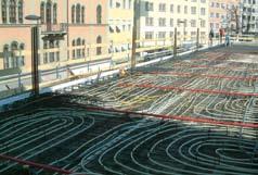
4 Table of contents Laying of firestop pipes in the concrete Part 1: Connecting of pipe work to the sprinkler outlet - Part 2: Pressure test of pipe work installation as strength test and leak test - Part 3: What must be considered during the concreting process? - Part 4: Access to connection of the pipe work in concrete - Part 5: Bridging of building joints - Part 6: Potential equalizing - Part 7: Pressurizing in the firestop-supply during the concreting process - Part 8: Influence of the concrete to the applied compounds Test Leakage test / Pressure diagram - Test record firestop system installation - Form: Enquiry for the chemical resistance References
 produced in a multi-layer extrusion process.")
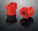
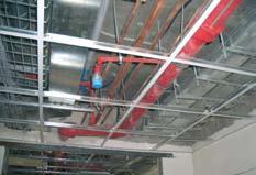
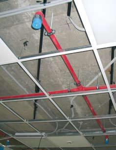
5 aquatherm firestopsprinkler pipe system aquatherm firestop offers an extensive range of pipes and fittings for the installation of fire sprinkler systems. The system is based on a fibre reinforced polypropylene pipe (faser composite pipe) produced in a multi-layer extrusion process. The material fusiolen PP-R FS, used for the production of these pipes, is a plastic whose profile of properties is designed for the special demands of the field of application. Both, the installer s request for easier processing and the demand for maximum safety in later application was taken into account during its development. aquatherm firestop is: - connection by fusion welding No sealants or adhesives are required for this permanent connection. - corrosion-proof Prevents the clogging of the sprinkler with corrosive products. This ensures a long, low-maintenance service life as well as trouble-free functioning of the system. The production of pipes and fittings is controlled according to the highest quality standards on latest injection moulding machines and extrusion lines. The high quality of our products is also ensured by extensive controls of incoming goods and the production process. The aquatherm quality management system is certified according to DIN EN ISO 9001:2000. aquatherm firestop- The advantages: certified and quality inspected connection by fusion welding resistant against corrosion and chemicals no accumulation of corrosion products low pipe roughness factor and high abrasion resistance heat and sound-insulating characteristics high impact strength leakproof connection of pipe and fitting by fusion technique not easily flammable acc. to din , building material class B1 low weight compared to metal pipes short processing time no gaskets - sealing elements are not required 3-layer pipe with fibre glass reinforced inner layer 4


6 Processing Fusion technique By the fusion of pipe and fitting the plastic melts to a homogeneous material. Pipe and fitting are heated quickly with specially provided welding tools and joined together - finished! Double material thickness at the joint giving double safety at the otherwise critical point of a pipe system. A permanent leakproof connection is created with the aquatherm fusion technique. 5


7 Processing Weld-in saddle technique Branches can easily be made by weld-in saddles, even post-installation. Material costs and processing time are reduced by using weld-in saddles. Whereas in case of tees three joints are to be processed, work is limited to mounting the saddle and the branch pipe only. Simply drill the pipe; heat up the saddle, pipe wall and surface; connect the parts. Finished! 6


 and the corresponding fittings LPCB 684")
 Poland (All pipe dimensions) Russia (All pipe dimensions) Iceland (All pipe")
8 International approvals for the application as sprinkler lines Fire protection requirements and standards for planning and construction of sprinkler systems vary locally. Thus, the application of firestop in any case has to be agreed and coordinated with the local national fire protection authorities, the constructor and the building insurers. Further certification either national or local are in process. Germany USA For the pipe dimension 25 mm up to 75 mm (DN15 - DN50) and the corresponding fittings LPCB 684 a Great Britain (All pipe dimensions) Ukraine (All pipe dimensions) Sweden (All pipe dimensions) Austria (All pipe dimensions) Poland (All pipe dimensions) Russia (All pipe dimensions) Iceland (All pipe dimensions) ZÚS Czech Republic V E LT E H Croatia (All pipe dimensions) VeriFire New Zealand Australia (All pipe dimensions) New Zealand 7
9 Handling Transport and storage firestop-pipes can be stored in all outside temperatures. Pipes should be stored and transported flat and fully supported along their length. Bending pressures are to be avoided. High impact should be avoided at externely low temperatures. Although firestop-pipes are extremely robust, it is recommended to treat the material always with care. UV resistance Pipes from fusiolen PP-R FS should not be installed (without protection) where subject to UV-radiation. All firestop-pipes and fittings are supplied in UV-protected packaging to bridge transport and assembly time. Ultraviolet rays have an influence on all high polymeric plastics. Hence, pipes should not be stored unprotected outside for a long time. The maximum storage time is (outside) 6 months. Fire bulkheading All fire prevention systems which can prove equivalent licensing are suited for the firestop pipe system. 8
10 Handling Procedures for additional repair Cut out damaged / leaking section and replace as for a new installation or repair with pipe repair stick (page 37). Chemical resistance On account of the special material qualities firestop-pipes and fittings provide extensive chemical resistance. firestop-transition connections and elements with brass inserts are not suitable for all media. The compatibility should be asked at aquatherm with media deviating from water. Please, use the Enquiry for the chemical resistance on page 49. Pipe friction loss The pressure loss caused by friction is to be calculated hydraulically with the Hazen-Williams-formula. The value to be used for C is 150, applicable for calculations of sprinkler installations and water supply. Equivalent lengths for the aquatherm firestop sprinkler pipe system The equivalent lengths of transition pieces, threaded connexions and tees (flow direction: straight) can be edequated with the socket values. Pipe dimension Nominal diameter DN15 DN20 DN25 DN32 DN40 DN50 DN65 DN80 Outer diameter firestop Article 25,0 mm 32,0 mm 40,0 mm 50,0 mm 63,0 mm 75,0 mm Equivalent pipe length in (m) 90,0 mm 110,0 mm without class 125,0 mm Socket 0,22 0,30 0,40 0,52 0,70 0,86 1,07 1,36 1,58 Reduction of 1dimension Reduction of 2 dimensions 0,27 0,37 0,48 0,63 0,83 1,03 1,28 1,63 1,90 0,36 0,49 0,64 0,84 1,11 1,37 1,71 2,17 2,53 Elbow 90 0,67 0,91 1,20 1,57 2,09 2,57 3,20 4,07 4,74 Elbow 45 0,33 0,46 0,60 0,78 1,04 1,28 1,60 2,03 2,37 Standard tee or cross flow direction branch 0,98 1,34 1,76 2,30 3,06 3,76 4,70 5,96 6,96 9

11 Pipe, Fittings Material: PP-R FS Pipe series: SDR 7,4 Unit: straight length á 6 m Colour: red/4 green stripes Firestop - pipe SDR 7,4 / B1 DN Diameter Wall thickness Internal Diameter Watercontent Weight x 2,8 mm ,8 14,4 0,152 0, x 3,5 mm ,5 18,0 0,236 0, x 4,4 mm ,4 23,2 0,379 0, x 5,5 mm ,5 29,0 0,590 0, x 6,9 mm ,9 36,2 0,919 1, x 8,6 mm ,6 45,8 1,444 1, x 10,3 mm ,3 54,4 2,054 2, x 12,3 mm ,3 65,4 2,943 3, x 15,1 mm ,1 79,8 4,403 5, x 17,1 mm ,1 90,8 5,669 6,475 Firestop - socket / B mm mm mm mm mm mm mm mm mm mm
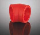
12 Fittings Firestop - reducer / B /20 mm /25 mm /32 mm /20 mm /32 mm /40 mm /20 mm /50 mm /50 mm /63 mm /63 mm /75 mm /63 mm /90 mm /90 mm /110 mm 1 1 Firestop - reducing socket / B1 innen/innen /50 mm /63 mm /75 mm 1 1 Firestop - elbow 90 / B mm mm mm mm mm mm mm mm mm mm
13 Fittings Firestop - elbow 90 / B1 female / male mm f/m mm f/m mm f/m mm f/m 5 1 Firestop - elbow 45 / B mm mm mm mm mm mm mm mm mm mm 1 1 Advice: Special elbows in diverse degree sizes on request Firestop - elbow 45 / B1 female / male mm f/m mm f/m mm f/m mm f/m 5 1 Firestop - tee / B mm mm mm mm mm mm mm mm mm mm
14 Fittings Firestop - reducing tee / B x 25 x 20 mm x 20 x 20 mm x 20 x 25 mm x 20 x 20 mm x 20 x 32 mm x 25 x 32 mm x 25 x 40 mm x 32 x 40 mm x 32 x 50 mm x 40 x 50 mm x 32 x 63 mm x 40 x 63 mm x 50 x 63 mm x 40 x 75 mm x 50 x 75 mm x 63 x 75 mm x 40 x 90 mm x 50 x 90 mm x 63 x 90 mm x 75 x 90 mm x 63 x 110 mm x 75 x 110 mm x 90 x 110 mm x 75 x 125 mm x 90 x 125 mm x 110 x 125 mm 1 1 Firestop - cross / B mm mm 5 1 Firestop - reducing tee / B / 32 mm / 32 mm / 40 mm / 32 mm / 40 mm / 50 mm
15 Fittings Firestop - end cap / B mm mm mm mm mm mm mm mm mm mm 1 1 Firestop - base part for sprinkler outlet for visible sprinkler for covered sprinkler 25 1 Firestop - upper part for sprinkler outlet /2 for visible sprinkler /4 for visible sprinkler for visible sprinkler /2 for covered sprinkler /4 for covered sprinkler for covered sprinkler 25 1 Firestop - plug for sprinkler outlet / /
16 Fittings Firestop - Temporary plug for plaster works made of PE foam for , -82, for , -92, for sprinkler outlet Art.-No , -92, -93 NEW Firestop - sprinkler outlet / / NEW Firestop - Plug for sprinkler outlet Plug for sprinkler outlet 1 1/ Plug for sprinkler outlet 1 1/ Plug for sprinkler outlet 2 1 NEW Firestop - plug for pressure test sprinkler outlet 1/ sprinkler outlet 3/ sprinkler outlet 1 1 Firestop - coupling plug 1/ /2 for Art-. No , -13, NEW
17 Fittings Firestop - weld-in saddle / B /20 mm /25 mm /20 mm /25 mm /20 mm /25 mm /32 mm /20 mm /25 mm /32 mm /40 mm /20 mm /25 mm /32 mm /40 mm /20 mm /25 mm /32 mm /40 mm /50 mm /20 mm /25 mm /32 mm /40 mm /50 mm /63 mm 5 1 With weld-on surface and weld-in socket to be fused with the inner wall of the pipe. The required tools for the fusion of Firestopweld-in saddles are listed on page 25: Firestop-weld-in saddle tools Fusiotherm -drill
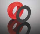
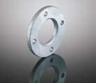
18 Fittings Firestop - weldable flange adapter / B1 with joint ring mm mm mm mm mm mm mm mm 1 1 Firestop - steel flange / B1 No. of holes Hole circle mm 4 85mm mm 4 100mm mm 4 110mm mm 4 125mm mm 4 145mm mm 8 160mm mm 8 180mm mm 8 210mm 1 1 Firestop - coupling screw / B mm mm mm mm mm 1 1 Incl. 2 flange adapters with gasket 17
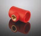
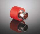
19 Transition piece Firestop - back plate elbow / B mm x 1/2 f mm x 3/4 f 10 1 Firestop - transition piece / B1 rund mm x 1/2 f mm x 1/2 f mm x 3/4 f mm x 3/4 f mm x 1/2 f mm x 1/2 f 10 1 Suitable for the connection to sprinkler outlets Firestop - transition piece / B1 with hexagon mm x 1/2 f mm x 3/4 f mm x 1/2 f mm x 3/4 f mm x 3/4 f * 32 mm x 1 f * 40 mm x 1 f mm x 1 1/4 f mm x 1 1/4 f mm x 1 1/2 f mm x 1 1/2 f mm x 2 f mm x 2 f mm x 1/2 f mm x 1/2 f 5 1 *Suitable for the connection to sprinkler outlets 18
20 Transition piece Firestop - transition piece / B1 with hexagon mm x 1/2 m mm x 3/4 m mm x 1/2 m mm x 3/4 m mm x 3/4 m mm x 1 m mm x 1 1/4 m mm x 1 m mm x 1 1/4 m mm x 1 1/4 m mm x 1 1/2 m mm x 1 1/2 m mm x 2 m mm x 2 m mm x 2 1/2 m mm x 3 m mm x 4 m 1 1 Firestop - transition elbow / B mm x 3/4 f mm x 1/2 f mm x 3/4 f mm x 1/2 f mm x 1/2 f mm x 3/4 f mm x 1 f mm x 1/2 f 5 1 Firestop - threaded branch tee / B x 1/2 f x 20 mm x 3/4 f x 20 mm x 1/2 f x 25 mm x 3/4 f x 25 mm x 1/2 f x 32 mm x 3/4 f x 32 mm x 1 f x 32 mm x 1/2 f x 40 mm x 1 f x 50 mm x 1 1/4 f x 50 mm
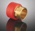
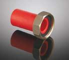
21 Transition piece Firestop - loose nut adapter / B1 Length: 100 mm threaded, with gasket mm x nut R mm x nut R 1 1/ mm x nut R 1 1/ mm x nut R mm x nut R 2 1/ mm x nut R 2 1/ mm x nut R 2 3/ mm x nut R 3 1/ mm x nut R Firestop - female part union / B1 ISO-Norm nut R 1 x 20 mm nut R 1 1/4 x 25 mm nut R 1 1/2 x 32 mm nut R 2 x 40 mm nut R 2 1/4 x 50 mm nut R 2 3/4 x 63 mm nut R 3 1/2 x 75 mm 1 1 Firestop - counterpart / B1 with welding socket and male thread for ISO-threaded joints mm x 1 m mm x 1 1/4 m mm x 1 1/2 m mm x R 2 m mm x R 2 1/4 m mm x R 2 3/4 m mm x R 3 1/2 m. 1 1 Firestop-metal composite fittings are manufactured from Fusiolen PP-R FS and brass. 20
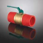
22 Transition piece Firestop -transition piece for groove connection / B mm x mm x 1 1/ mm x 1 1/ mm x mm x mm x mm x Firestop - weld-in saddle / B /25 mm x 1/2 f /25 mm x 1/2 f /25 mm x 1/2 f /25 mm x 1/2 f /25 mm x 1/2 f /25 mm x 1/2 f /25 mm x 1/2 f /25 mm x 3/4 f /25 mm x 3/4 f /25 mm x 3/4 f /25 mm x 3/4 f /25 mm x 3/4 f /25 mm x 3/4 f /25 mm x 3/4 f * 75/32 mm x 1 f * 90/32 mm x 1 f * 110/32 mm x 1 f * 125/32 mm x 1 f 5 1 with female thread and hexagon socket, with weldin weld-on surface and weld-in socket to be fused with the inner wall of the pipe The required tools for the fusion of Firestop-weld-in saddles are listed on page 25: - weld-in saddle tools Fusiotherm -drill * Suitable for the connection to sprinkler outlets Firestop - ball valve PP/MS / B mm mm mm mm mm mm 1 1 Firestop-metal composite fittings are manufactured from Fusiolen PP-R FS and brass. 21
23 Cutter & welding devices The tools mentioned with the name Fusiotherm are used for the installation of Firestop products, too. Fusiotherm - pipe cutter for pipe ø mm for pipe ø mm for pipe ø mm 1 1 Fusiotherm - pipe cutter for pipe ø mm 1 1 Important: Do not cut the Firestop- pipes with customary hack saws. Firestop- pipes can be cut with customary saws equipped with saw blades suitable for plastic. Fusiotherm - manual welding device (500 W) for pipe ø mm 1 1 With base and case for tools Fusiotherm - manual welding device (800 W) for pipe ø mm 1 1 With base and case for tools Fusiotherm - manual welding device (1400 W) for pipe ø mm 1 1 With base and case for tools 22
24 Welding machines The tools mentioned with the name Fusiotherm are used for the installation of Firestop products, too. Fusiotherm - welding machine (1400 W) for pipe ø mm 1 1 Incl. welding tools mm (: ) Fusiotherm -manual welding device (1400 W) and wooden transport case Fusiotherm - electric welding jig for pipe ø mm 1 1 incl. spare battery, charging station and metal case Support: on request Fusiotherm - base for Fusiotherm - welding machine (1400 W) Light for pipe ø mm Fusiotherm -manual welding device (1400 W) and wooden transport case Fusiotherm - temperature measuring device to check the correct welding temperature 23
25 Welding tools & accessories The tools mentioned with the name Fusiotherm are used for the installation of Firestop products, too. Fusiotherm - thermocolour pencil to check the correct welding temperature Fusiotherm - welding tool mm mm mm mm mm mm mm mm mm mm mm 1 1 Fusiotherm - repair kit mm mm 1 1 to close pipe holes up to 10 mm (pipe repair stick 60600) Firestop - repair stick /11 mm 1 1 Material: Fusiolen PP-R FS to close pipe holes up to 10 mm.tool: Fusiotherm -repair kit ( ). 24
26 Welding tools & drills The tools mentioned with the name Fusiotherm are used for the installation of Firestop products, too. Fusiotherm - welding tool for welding saddles of art.-no and x 20/25 mm x 20/25 mm x 20/25 mm x 32 mm x 20/25 mm x 32 mm x 40 mm x 20/25 mm x 32 mm x 40 mm x 20/25 mm x 32 mm x 40 mm x 50 mm x 20/25 mm x 32 mm x 40 mm x 50 mm x 63 mm 1 1 Fusiotherm - drill for the mounting of weld-in saddles & 25 mm (for pipe mm) mm mm mm mm 1 1 * may only be used in fixed drilling machines! Firestop - Extraction tool for sprinkler outlet Art- No NEW 25


27 Part A: Mounting of the welding tools 1. Important! Only use original fusiotherm -welding devices and fusiotherm -welding tools. 2. Assemble and tighten the cold welding tools manually. 3. All welding tools must be free from impurities. Check, if they are clean before assembling. If necessary clean the welding tools with a non fibrous, coarse tissue and with spirit. 4. Place the welding tools, so that there is full surface contact between the welding tool and the welding plate. Welding tools over Ø 40 mm must always be fitted to the rear position of the welding plate. 5. Plug in the welding device and check, if operating lamp is on. Depending on the ambient temperature it takes minutes to heat-up the welding plate. The heat-up phase ends, when the temperature pilot lamp blinks and a signal is audible. Right Wrong Electric power supply: The power supply must coincide with the data on the type plate of the welding device and must be protected according to the local regulations. To avoide high power loss, the conductor cross-section of the used extension cables must be selected according to the power input of the welding devices. 26

28 Part A: Heat-up phase 6. During the heat-up phase tighten the welding tools carefully with the Allen Key. Take care that the tools fully contact the welding plate. Never use pliers or any other unsuitable tools, as this will damage the coating of the welding tools. 7. The required temperature to weld the firestop-system is 260 C. Acc. to DVS-Welding Guidelines the temperature of the welding device has to be checked at its tool before starting the welding process. This has to be done with a fast indicating thermometer or alternatively with a fusiotherm -thermocolour crayon. (see Fusion part B, item 2 ) ATTENTION: First welding at the earliest 10 minutes after reaching the welding temperature DVS 2207, Part 11. Heating plate Temperature pilot lamp (yellow) Welding tool Operating lamp (green) Welding tool 8. A tool change on a heated device requires another check of the welding temperature at the new tool (after heat-up phase). 9. If the device has been unplugged, i. e. during longer breaks, the heat-up process has to be restarted (from item 5). 10. After use unplug the welding device and cool down. Water must never be used to cool the welding device, as this would destroy the heating resistances. 27
29 Part A: Handling 11. Protect fusiotherm -welding devices and tools against impurities. Burntit particles may result in an incorrect fusion. The tools may be cleaned with fusiotherm -cleaning wipes, Always keep the burntin welding tools dry. If necessary, dry them with a clean, non fibrous tissue. 12. For perfect fusion, damaged or dirty welding tools must be replaced, as only undamaged tools ensure a perfect fusion welding. 13. Never attempt to open or repair a defective device. Return the defective device for repair. 14. Check the operating temperature of the fusiotherm - welding devices regularly by means of suitable measuring instruments. Part A: Guidelines 15. For the correct handling of welding machines the following must be observed: General Regulations for Protection of Labour and Prevention of Accidents and particularly the Regulations of the Employers Liability Insurance Association of the Chemical Industry regarding Machines for the Processing of Plastics, chapter: Welding Machines and Welding Equipment. 16. For the handling of the fusiotherm -welding machines, devices and tools please observe General Regulations DVS 2208 Part 1 of the German Association for Welding Engineering, Registered Society (Deutscher Verband für Schweißtechnik e. V.). 28


30 Part A: Checking of devices and tools 1. Check, if the fusiotherm -welding device and tool correspond to the guidelines Fusion Part A. 2. All devices and tools in use must have reached the required operating temperature of 260 C in use. This needs a separate, compulsory test, acc. to DVS-Welding Guideline Fusion Part A, item 8. The control of the operating temperature can be made with fast indicating thermometers. Suitable measuring instruments must offer a temperature measurement of up to 350 C with a high accuracy. Alternatively it is also possible to check the welding temperature with the fusiotherm -thermocolour crayon. The application of the special thermo-colour chalk in the aluminium crayon enables an exact reading with a tolerance of +/- 5 K to heated surfaces. Application: After the temperature pilot lamp of the welding device has indicated the end of the heat-up period, put a firm chalk line on the heated external surface of the welding tool. The colour must change within 1-2 seconds. If the temperature is too high, the colour will change immediately and if it is too low (below 260 C) it will change after 3 or more seconds. If the colour does not change within 1-2 seconds another temperature test has to be carried out, respectively the control of the welding device is required. Temperature control by means of surface temperature measuring instrument. Temperature control by chalk. before after 29


31 Part B: Preparation for the fusion 3. Cut the pipe right-angled to the pipe axis. Only use fusiotherm -pipe cutters or other suitable cutting tools. Take care that the pipe is free from burrs or cutting chips and remove if necessary. 4. Mark the welding depth at the end of the pipe with the enclosed pencil and template. 5. Mark the desired position of the fitting on the pipe and / or fitting. The auxiliary markings on the fitting and the continued line on the pipe may be used as a help. Cutting of the pipe Marking of the welding depth The fusion is subject to the following data Pipe external-ø Welding depth Heat-up time Welding time Cooling time mm mm sec. DVS sec min , , , , , , , , , , The General Guidelines for Heated Socket Wel- ding acc. to DVS 2207 Part 11 apply. 30

32 Part B: Heat-up of pipe and fittings 6. Push the end of the pipe, without turning, up to the marked welding depth into the welding tool and at the same time the fitting, without turning, as far as it will go on the tool. It is essential to observe the above mentioned heating times. Pipes and fittings of the dimensions Ø 75 to 125 mm may only be welded with welding device (or with machine 50147). On using the fusiotherm -welding machine a separate operating instruction has to be observed. ATTENTION: The heating time starts, when pipe and fitting have been pushed with the correct welding depth on and in the welding tool. Not before! Part B: Setting and alignment 7. After the stipulated heat-up time quickly remove pipe and fitting from the welding tools. Join them immediately, without turning, until the mark welding depth is covered by PP-bead of the fitting. ATTENTION: Do not push the pipe too far into the fitting, as this would reduce the bore and in an extreme case may close the pipe. 8. The joint elements have to be fixed during the specified processing time. Use this time to correct the connection. Correction is restricted to the alignment of pipe and fitting. Never turn the elements or align the connection after the processing time. 9. After the cooling period the fused joint is ready for use. The result of the fusion of pipe and fitting is a permanent material joining of the system elements. Unrivaled connection technique with security for a life-time! Warming Joining, fixing and aligning! 31
33 Visual inspection of fusion seam Normally on fusioning a bead is formed around the entire circumference at the edge of the socket. This bead is an indication of proper welding Incorrect shape of bead Different shape of bead (b) or non-existent bead at one or at both ends (a) (partial or total extent), resulting from: temperature of heating tool is too low (a) heat-up time too short (a) unacceptable tolerances (a and b) excessive temperature of heating tool (b) heat-up time too long (b) Single shape of bead, resulting from: heat-up time too short temperature of heating tool is too low unacceptable tolerances heat-up of only one welding-part Excessive melting, resulting from: temperature of heating tool is too high misaligned movement of welding-part, e.g. by inadequate fixing unacceptable tolerances Elbow variance Partially or double-sided inclined welded pipe into the socket without or with slight bracing, resulting from: machinery defect false installation Acceptable, if e 2 mm Mistake of bonding by improper pipe insertion, resulting from: heat-up time too short pipe ends not at 90 (right-angled) heating temperature too low axial movement during cooling time change-over time too long Acceptable up to 0.1 x d and 0.15 x socket depth 32
34 Visual inspection of fusion seam correct fusion welding a b e d x The visual inspection may be only a first indication of the welding seam quality. But it is not a replacement for the leak test, which has to be carried out after the completion of the installation. Source: DVS , to purchase at DVS-publisher, Düsseldorf Copyright Publisher for fusion and related procedures DVS-Verlag GmbH 33
35 Part C: Weld-in saddles For pipe external diameters of 40, 50, 63, 75, 90, 110, 125 mm D d R h Sensorwells Drill Welding Tool mm mm f mm ømm /20 mm , /25 mm , /20 mm , /25 mm , /20 mm , /25 mm , /32 mm , /20 mm , /25 mm , /32 mm , /40 mm , /20 mm , /25 mm , /32 mm , /40 mm , /20 mm , /25 mm , /32 mm , /40 mm , /50 mm , /20 mm , /25 mm , /32 mm , /40 mm , /50 mm , /63 mm , /25x1/2" f. 40 1/2" 39, /25x1/2" f. 50 1/2" 39, /25x1/2" f. 63 1/2" 39, /25x1/2" f. 75 1/2" 39, /25x1/2" f. 90 1/2" 39, /25x1/2" f /2" 39, /25x1/2" f /2" 39, /25x3/4" f. 40 3/4" 39, /25x3/4" f. 50 3/4" 39, /25x3/4" f. 63 3/4" 39, /25x3/4" f. 75 3/4" 39, /25x3/4" f. 90 3/4" 39, /25x3/4" f /4" 39, /25x3/4" f /4" 39, /32x1" f. 75 1" 43, /32x1" f. 90 1" 43, /32x1" f " 43, /32x1" f " 43,

. 4. The welding surfaces have to be clean and dry.")


36 Teil C: Weld-in saddles 1. Before starting the welding process, check if the fusiotherm - welding devices and tools meet the requirements of Fusion Part A. 2. The first step is to drill through the wall of the pipe at the point intended for the outlet by using the fusiotherm -drill. branch 20/25 mm: 50940/41 branch 32 mm: branch 40 mm: branch 50 mm: branch 63 mm: The welding device/saddle welding tool must have reached the required operating temperature of 260 C (check with reference to Fusion Part B, item 2 ). 4. The welding surfaces have to be clean and dry. 5. Insert the heating tool on the concave side of the weld-in saddle tool into the hole drilled in the side wall of the pipe until the tool is completely in contact with the outer wall of the pipe. Next the weld-in saddle spigot is inserted into the heating sleeve until the saddle surface is up against the convex side of the welding tool. The heating time of the elements is generally 30 seconds. 6. After the welding tool has been removed, the weld-in saddle spigot is immediately inserted into the heated, drilled hole. The weld-in saddle should then be pressed on the pipe for about 15 seconds. After being allowed to cool for 10 minutes the connection can be exposed to its full loading. The appropriate branch pipe is fitted into the sleeve on the fusiotherm -weldin saddle using conventional fusion technology. By fusing the weld-in saddle with the pipe outer surface and the pipe inner wall the connection reaches highest stability. Drilling through the pipe wall Heat-up of pipe...and fitting Joining 35

37 Part D: fusiotherm -welding machine One wooden transport box for the welding machine One machine body with substructure, welding plate One set clamping jaws composed of 8 two-part jaws bars for pipes and fittings, diameter 25, 32, 40, 50, 63, 75, 90, 110, 125 mm One fusiotherm -welding tool diameter 50, 63, 75, 90, 110, 125 mm One welding device : One Allan key and tool change clamp One fusiotherm -thermocolour crayon One Installation manual The fusiotherm -welding machine was especially developed for stationary welding of pipe and fittings with an external diameter of 50 to 125 mm. This machine is equipped with a hand crank to facilitate a precise pre-assembly of complicated installation parts. The fusion is subject to the following data Pipeexternal-Ø Welding depth Heating time Welding time Cooling time mm mm sec. DVS sec min , , , , , , The General Guidelines for Heated Tool Socket Welding acc. to DVS 2207 Part 11 apply. Part D: Support intervals Firestop-pipe SDR 7.4 Table to determine support intervals in conjunction with outside diameter. Pipe diameter d [mm] Support intervals in cm
, adjust clamping jaws 63 125 mm coarsely. Mark welding depth with the template at the pipe. 2.")


. In addition the firestop-system offers the possibility of repair by repair stick.")
38 Part E: welding machine prisma-light with heating plate without tools clamping fixture for fixing the prisma-light e. g. at the work bench 1. Check machine: temperature lamp blinks after reaching the welding temperature (260 C), adjust clamping jaws mm coarsely. Mark welding depth with the template at the pipe. 2. Fix the fitting against the clamping jaws. 3. Place the pipe loose in the opposite clamping jaws. 4. Position the welding device centrically to the pipe-fitting axis and remove it. 5. Lock the front calibration knob and drive up the slide as far as it will go. 6. In this position push the pipe against the fitting and fix it with the clamping jaws. 7. Regulate the welding time according to the table on page 36 place the welding device and push the fitting and pipe slowly as far as it will go up to the marking. 8. The heating time starts when pipe and fitting are completely pushed on the tool. When heating time is complete slide return the slide, remove the heating device quickly and join the pipe and fitting. 9. Consider cooling times from the table on page 36. More detailed information can be taken from the enclosed operating manuals. Teil F: Repair Heat-up Damaged pipes may be repaired - as already mentioned - by fusion welding (see part B). In addition the firestop-system offers the possibility of repair by repair stick. The suitable welding tool ( 50307/11) and the repair stick ( ) are described on page 24. The installation information is enclosed with the welding tool, but may also be ordered separately. Pipe repair stick Cutting 37
 is screwed with 4 screws on the shuttering.")
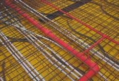
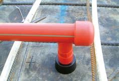
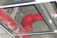
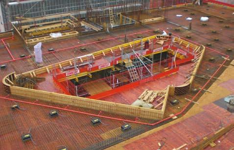
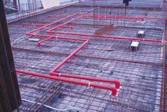
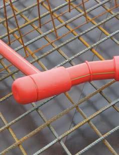
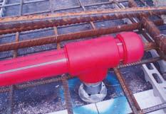
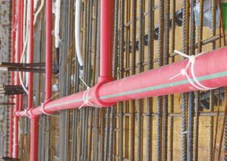
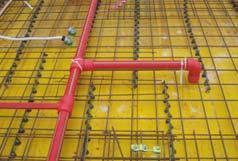
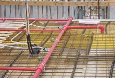
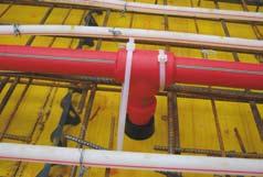
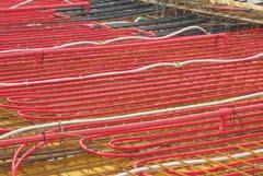
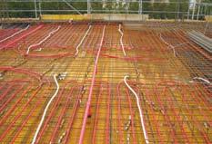
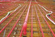
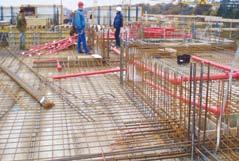
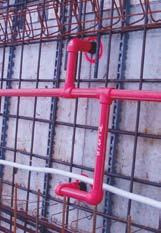
39 Laying of aquatherm firestop-pipes in the concrete Part 1: Connecting of pipe work to the firestop sprinkler outlet The connection is described in picture 1 as follows: The base part of the sprinkler outlet (1) is screwed with 4 screws on the shuttering. Brass plug (2), upper part of the sprinkler outlet (3) and firestop connection piece (4) are connected to each other and plugged onto the base part of the sprinkler outlet (1), so that part 3 is flush with the shuttering. Picture Detailed information regarding the different dimensions of the sprinkler outlet please take from tables on page 14! Colour of plastic sleeve may differ. 38
 the base part of the sprinkler outlet (1) is pulled out of the upper part of the sprinkler outlet (3).")
 must be pulled out of the concrete easily with the firestop extraction tool (Art- No. 50290).")
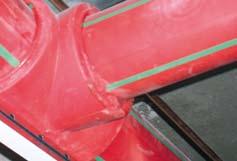
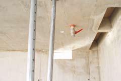
40 Laying of aquatherm firestop-pipes in the concrete The firestop sprinkler connection is finished (picture 2). Picture 2 When removing the shuttering (after pouring of the concrete) the base part of the sprinkler outlet (1) is pulled out of the upper part of the sprinkler outlet (3). The brass plug (2) is unscrewed from the firestop-connection piece (part 4). Now, the upper part of sprinkler outlet (3) must be pulled out of the concrete easily with the firestop extraction tool (Art- No ). The sprinkler connection (picture 3) can be completed very easily. The, acc. to CEA 4001, required distance from the sprinkler head to the completed ceiling, can be accomplished with the compensating fitting from the sprinkler connection thread up to the firestop connecting piece (see drawing page 40). Picture 3 39
41 Laying of aquatherm firestop-pipes in the concrete pre-assembly Vormontage sprinkler outlet Sprinkler-Anschlussdose Visible sprinkler completed-assembly Fertigmontage Covered sprinkler Ausgleichsfitting Standard extension compensating fitting a a = gen. CEA 4001 completed-assembly Fertigmontage 40
42 Laying of aquatherm firestop-pipes in the concrete concrete Firestop outlet 1 1 / 4, 1 1 / 2 und 2 2 Firestop sprinkler outlet for covered sprinkler 1 / 2, 3 / 4 und 1 3 Firestop sprinkler outlet for visible sprinkler 1 / 2, 3 / 4 und 1 4 firestop to steelpipe adapter ATTENTION All upper parts of sprinkler outlet must be pulled out of the concrete with the firestop extraction tool (Art- No ). 41

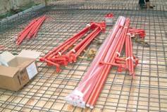
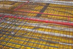
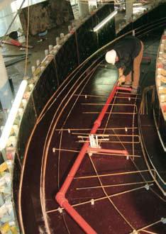
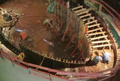
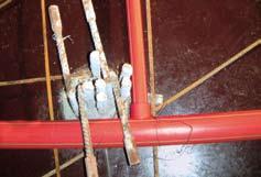
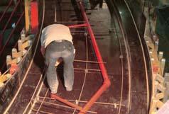
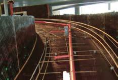
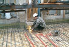
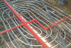
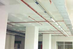
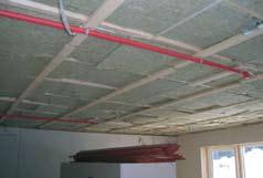
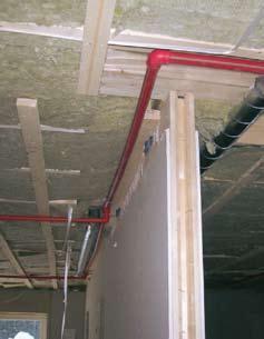
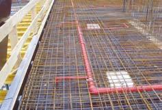
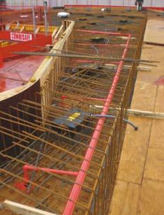
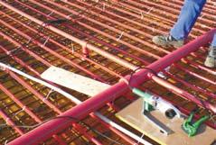
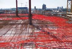
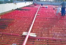
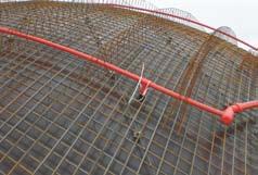
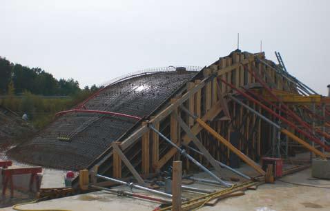
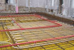
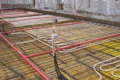
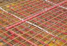
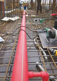
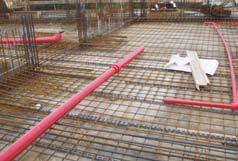
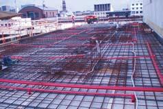
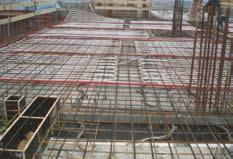
43 Laying of aquatherm firestop-pipes in the concrete Part 2: Pressure test of pipe work installation as strength test and leak test Please refer to the information on page Part 3: What must be considered during the concreting process? All sprinkler connections have to be locked with cable clips. See picture. The pipe sections must be fixed every 1.5 to 2 m in a way (using pipe hangers or lacing cord) to avoid sagging or bowing during the concreting process. It is important, that the pipe work is completely embedded without any hollow spaces (cavities). The entering of the pipes during the concreting process must be avoided. The compacting of the concrete with concrete vibrators in the pipe area should be carried out carefully. Impacts, especially at low temperatures (below +5 C) must be avoided. Open pipes and connections must be closed before the concreting. The competent office of VDE shall be informed about the date of the pressure test and the concreting. VDS decides on their participation during the pressure test and/or the concreting process. 42

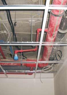
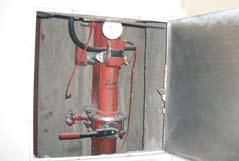
44 Laying of aquatherm firestop-pipes in the concrete Part 4: Access to connection of the pipe work in concrete Option 1: The pipe work in the concrete should be connected to the supply pipe, that the connection can be accessed in case of damage. This may accomplished as follows: Before applying the concrete on the ceiling, a form work (casing) should be constructed around the connection (allow enough space for installation work). The connection is embedded in sand or similar fill of F90-quality in the form work. The ceiling can be filled with concrete, now. After striking the ceiling, the connection can be laid open and is now accessible. The subsequent sealing of the cavity in the ceiling can be made with elements of F90-quality. The access must be visible at all times (indicated on the drawing or by marking the ceiling). Option 2: Before casting the connection can be packed in a Rockwool-fire protection panel Conlit 150 U (allow enough space for installation work). This panel has the following features: light, water-repellent, pressure-resistant, self-supporting rockwool panel covered with glass grid Fields of application: fire protection covering for steel construction F30 A-F180-A, Increase of fire resistance class of concrete coverings. Not flammable A2 acc. to DIN 4102, Part 1. Melting point >1000 C. After shuttering of the ceilings the fire protection panel Conlit 150 U can remain in the completed ceiling and can be adjusted to the structure of the concrete ceiling by plastering. The access shall be visible, as in option 1, at all time. Drawing according to options 1 and 2 riser opening for inspection pipe 43
45 Laying of aquatherm firestop-pipes in the concrete Damaged pipe work in concrete, e.g. by drilling work Damaged pipe work can be repaired by fusion welding (see firestop-sprinkler pipe system, Part B). The firestop system can also be repaired using the pipe repair stick (see firestop sprinkler system, Part E) Part 5: Bridging of expansion joints The expansion or firestop-pipes depends on the temperature of the pipe material. Cold water supplies cause hardly any expansion for a normal assembly nor do normal outside temperatures. The expansion need not to be considered when laying firestop-pipes in the concrete. Rising pressures- and tensile stresses are not critical, as they are absorbed by the material. However, if it is necessary to bridge the expansion joints, the firestop pipes must be equipped with an approx. 25 cm protection pipe at both ends of the joint. A confirmation of the responsible architect resp. structural designer must certify that no lengthwise movements in the expansion joints can be expected. The coefficient of expansion of firestop-pipes is mm/mk The coefficient of expansion of concrete is mm/mk. Part 6: Potential equalizing The VDE 0190 Part 410 and 540 requires a potential equalizing between all kinds of earth conductors and the existing conductible potable and waste water supplies and heating pipes. As firestop is not a conductible pipe system, it cannot be used for potential equalizing and thus needs no earth wiring. The potential equalizing is made according to VDE-standard from the building parts, which have to be earth wired, directly to the potential equalizing rail to the planned position. The constructor or site manager must advise the client or his representative, that an approved electrician must check, if the firestop installation does not affect the existing electrical protection and earth wiring measurements (VOB Part C, generaltechnical conditions of contract ATV). 44
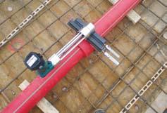
46 Laying of aquatherm firestop-pipes in the concrete Part 7: Pressurizing in the firestop-supply during the concreting process During the concreting process the pipe must be pressurized with the admissible operating pressure, so that a damaged point is visible at once. After the pressure test the admissible operating pressure is kept by shut off of the respective pipe. The applied measuring devices must grant a correct reading of pressure changes of 0.1 bar. The pressure measuring device shall be installed at the deepest point of the pipe system. Part 8: Influence of the concrete to the applied compounds The firestop-pipe system contains all required compounds for a complete system installation. Mixed installation with non-system and/or non-material compounds are not required. All material is resistant to corrosion. The threads of the firestop-sprinkler connection fittings are made from brass (CuZn36Pb2As). Experiences with this material confirm that the alloy has an excellent resistance against concrete. The general building regulations have to be complied with locally. If special chemical additives (retarder, etc.) are applied, information from the manufacturer of the concrete should be gathered; refer to aquatherm for suitablity. 45
47 Leakage test All pipelines have to be hydraulically pressure tested. The test pressure must be 1.5 times of the operating pressure. Due to the material properties of firestop pipes a pressurization causes an expansion of the pipe, which influences the test result. Different temperatures of pipe and test medium also lead to alterations of pressure. A temperature change of 10 K corresponds to a pressure difference of 0.5 to 1 bar. The pressure test of the firestop-system should be made with a constant temperature of the medium. The hydraulic pressure test requires a preliminary, principal and final test. In the preliminary test the system is pressurized with the 1.5 times of the maximum operating pressure. This test pressure has to be re-established twice within 30 minutes within an interval of 10 minutes. After a test time of a further 30 minutes the test pressure must not drop more than 0.6 bar. No leakage may appear. The preliminary test is to be followed directly by the principal test. Test time is 2 hours. Now the test pressure taken from the preliminary test may not fall more than 0.2 bar. Upon completion of the preliminary and principal tests the final test must be conducted. In the final test the system is pressurized in a frequency of 5 minutes with a changing test pressure of 10 and 1 bar. Between each test course the pressure has to be released. No leakage must appear at any point of the tested system installation. Measuring of the test pressures Measuring has to be done with a manometer allowing a perfect reading of a pressure change of 0.1 bar. The manometer has to be placed at the deepest point of the installation. Test record A record of the hydraulic pressure test has to be prepared and signed by the client and contractor stating place and date (see page 48). 46
48 Leakage test / Pressure diagram Preliminary- and Principal test max. max. Operation Betriebsdruck pressure x 1,5 x 1,5 p in bar Preliminary Vorprüfungtest Principal Hauptprüfung test 30 min 60 min 180 min t in min Final test 10 bar 1 bar 2 min 4 min 2 min 4 min 2 min 4 min 5 min 10 min t in min 47
49 Test record firestop system installation Description of the installation Preliminary test Place: Object: max. working pressure x 1.5 bar Pipe-lengths: Ø 16 mm m Ø 20 mm m Ø 25 mm m Ø 32 mm m Ø 40 mm m Ø 50 mm m Ø 63 mm m Ø 75 mm m Ø 90 mm m Ø 110 mm m Ø 125 mm m Pressure drop after 30 minutes: bar (max. 0,6 bar) Result preliminary test: Principal test Working pressure:: bar (Result preliminary test) Pressure after 2 hour: bar (max. 0,2 bar) Highest tapping (over manometer) m Result principal test: Start of the test: End of the test: Test period: Client: Contractor: Place: Date: Stamp / Signature Final test* 1. working pressure 10 bar: bar at least 2 minutes, then working pressure 1 bar: bar at least 2 minutes, then 2. working pressure 10 bar: bar at least 2 minutes, then working pressure 1 bar: bar at least 2 minutes, then 3. working pressure 10 bar: bar at least 2 minutes, then working pressure 1 bar: bar at least 2 minutes, then 4. working pressure 10 bar: bar at least 2 minutes, then working pressure 1 bar: bar at least 2 minutes, then * Unpressurize the pipe between each cycle 48
50 Enquiry for the chemical resistance Enquiry for the chemical resistance of the aquatherm firestop-pipe system aquatherm GmbH Technical department Biggen 5. D Attendorn Phone: Fax: Internet: Installer: Field of application:: Installer Fluid transported: Company Operating temperature C Street Working pressure bar PLZ / Ort Service life h / d Telefon Concentration % Telefax Building project: Ambient medium: Ambient temperature C Ambient pressure bar Building project: Street City not Data sheets enclosed enclosed Fluid transported Place, Date / Signature Ambient medium 49
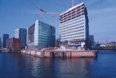


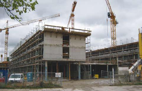
51 References Office Building Römischer Hof Berlin, Germany Spiegel Building Hamburg, Germany 50


52 References The European Patent Office Munich, Germany 51


53 References Public services munich, technology center Munich, Germany 52


54 References HYPO-Center Innsbruck, Austria Foto: Hypo Tirol Bank AG 53


55 References Raschal - Centre for children surgery and traumatology Moscow, Russia Foto: Hypo Tirol Bank AG 54


56 References Shopping Centre Moscow, Russia Office Building Moscow, Russia 55


57 References Hotel Sweden Carpet warehouse Turkey 56


58 References Pandion Vista Cologne, Germany 57


59 References Aachner Münchener Insurance Aachen, Germany Federal Archives Berlin, Germany Unionsbräu Dortmund, Germany 58


60 References Coffe Plaza Hamburg Hafencity, Germany Dürr Campus Stuttgard, Germany 59


61 References Dornier Museum Friedrichshafen, Germany Metropolis Hamburg, Germany 60


62 References Hans Sachs Building Gelsenkirchen, Germany 61


63 References Central office HDI-Gerling Insurance Hannover, Germany 62


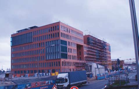

64 References Crystalbuilding Hamburg fish market, Germany 63


65 References Office building Rödingsmarkt Hamburg, Germany Überseequartier Hamburg, Germany 64

66 INNOVATIVE PIPE SYSTEMS - SUCCESSFULL WORLDWIDE Fusiotherm climatherm aquatherm lilac aquatherm ISO aquatherm aquatherm SHT climasystem Korrosionsresistente Rohrleitungsnetze Verteilerbau Trinkwasser- und Heizkörperanbindesystem aquatherm SHT Deckenkühlung Nahwärmeleitungen Rasenheizung Industrieanwendungen (z. B. Druckluftanlagen) Industriebodenheizung corrosion resistant pipes distribution construction Potable water and radiator connection system aquatherm SHT ceiling cooling district heating under-soil heating industrial applications (e. g. compressed air plants) industrial floor heating Best.-Nr. DE09065 Order-No. DE09065 Eisflächenkühlung Freiflächenheizung Fußbodenheizung (Alt-/Neubau) Decken-/Wandheizung Naß- & Trockenbau Sportbodenheizung Wasserlöschanlagen Nutzwasser Trinkwassernetze ice surface cooling open space heating underfloor heating (old/new buildings) ceiling/wall heating wet & dry construction sports floor heating system fire-extinguishing system recycled water potable water pipe systems info@aquatherm.de aquatherm GmbH Biggen 5 D Attendorn Phone: +49 (0) Fax: +49 (0) Wilhelm-Rönsch-Str. 4 D Radeberg Phone: +49 (0) Fax: +49 (0) info@aquatherm.de Order-No.: E Edition: 01/2011
Edition: aquatherm red. Pipe system made of polypropylene for fire sprinkler systems. aquatherm state of the pipe
 Edition: 05.2014 aquatherm red Pipe system made of polypropylene for fire sprinkler systems aquatherm state of the pipe Our sales and delivery conditions (January 2014) and the contacts of our technical
aquatherm red Pipe system made of polypropylene for fire sprinkler systems aquatherm state of the pipe
 aquatherm red Pipe system made of polypropylene for fire sprinkler systems aquatherm state of the pipe Our sales and delivery conditions (January 2012) and the contacts of our technical sales and distribution
aquatherm red aquatherm state of the pipe Pipe system made of polypropylene for fire sprinkler systems
 Edition: 05.2016 aquatherm red - Pipe system made of polypropylene for fire sprinkler systems aquatherm red Pipe system made of polypropylene for fire sprinkler systems aquatherm state of the pipe Our
aquatherm red Pipe system made of polypropylene for fire sprinkler systems aquatherm state of the pipe
 aquatherm red Pipe system made of polypropylene for fire sprinkler systems aquatherm state of the pipe Our sales and delivery conditions (January 2012) and the contacts of our technical sales and distribution
aquatherm greenpipe climatherm aquatherm lilac
 Technical Information for aquatherm greenpipe pressure pipe system for potable water, food processing, and hygienically sensitive applications climatherm pressure pipe system for hydronic, compressed air,
EPIC B2134 J345 X721 1/2015
 EPIC B2134 J345 X721 1/15 Ekoplastik System made from granulate of leading European producers unique 3 layer pipe reinforced with basalt fiber new materials of 4. generation PP-RCT high pressure and temperature
Ø mm. SYSTEM KAN-therm. High quality for reasonable price TECHNOLOGY OF SUCCESS ISO 9001
 Ø 16 110 mm SYSTEM KAN-therm PP High quality for reasonable price TECHNOLOGY OF SUCCESS Contents 3 System KAN-therm PP The material... 94 Sanitary systems installation... 95 Pipes... 95 Thermal elongation...
Aquatherm Australia Pty Limited Technical Support Australian Version 1 Edition 03/10
 AUSTRALIA PROOF CONTENTS 0 Features fusiolen PP-R 3 Permissible working pressures 5 Fields of application of the fusiotherm 6 and climatherm-pipe systems Fusion for fusiotherm, climatherm and aquatherm
climatherm We set the standards for quality and reliability! P I P E S Y S T E M S
 climatherm We set the standards for quality and reliability! P MADE IN I P E S Y S T E M S GERMANY aquatherm-climatherm The climatherm-pipe system includes all elements for the pipe system installation
Technical Instruction aquatherm red pipe
 1.1 Scope 2 1.2. Definitions 2 1.2.1 aquatherm red pipe SDR7,4 MF HI 2 1.2.2 aquatherm red pipe fittings 2 1.3 General 2 1.4 Use of aquatherm red pipe in sprinklered installations 2 1.4.1 Occupancy 2 1.4.2
DUCTILE IRON PIPES AND FITTINGS DETAILED PRODUCTS SPECIFICATIONS
 DUCTILE IRON PIPES AND FITTINGS DETAILED PRODUCTS SPECIFICATIONS General All Materials shall be EN, ISO or equivalent standard and shall be supplied from approved manufacturers. According to the International
Specification texts FRIAFIT sewage system
 Specification texts FRIAFIT sewage system Norm Conformity The FRIAFIT sewage system of PE 100 complies with EN 12666 and hence is deemed a regulated construction product. It therefore does not need general
PLASTIC FITTINGS Avenue Edmonton, AB Canada T6E 5Z7. Toll Free: Phone: (780) Fax: (780)
 Fax: (780)") 9333 45 Avenue Edmonton, AB Toll Free: 1-800-272-9693 Phone: (780) 436-1930 Fax: (780) 435-4849 info@can-con.com TABLE OF CONTENTS PLASTIC FITTINGS POLYETHYLENE PIPE...- 1 - SERVICE RISERS... - 3 - TRANSITION
9333 45 Avenue Edmonton, AB Toll Free: 1-800-272-9693 Phone: (780) 436-1930 Fax: (780) 435-4849 info@can-con.com TABLE OF CONTENTS PLASTIC FITTINGS POLYETHYLENE PIPE...- 1 - SERVICE RISERS... - 3 - TRANSITION
Sanitary Installations. Product Catalogue.
 Sanitary Installations Product Catalogue www.hydroplast.de Pipe SDR 11 Art. no D s kg/m m/pack G11001 20 1,9 0,107 200 G11002 25 2,3 0,164 160 G11003 32 2,9 0,267 80 G11004 40 3,7 0,412 60 G11005 50 4,6
Submittal for Aquatherm Piping System
 Submittal for Aquatherm Piping System Project Name: Project Location: Date: To whom it may concern, We are proposing to upgrade the piping parts on the above project to the polypropylene Aquatherm Green
Edition: aquatherm red. Pipe system made of polypropylene for fire sprinkler systems. aquatherm state of the pipe
 Edition: 01.2015 aquatherm red Pipe system made of polypropylene for fire sprinkler systems aquatherm state of the pipe Our sales and delivery conditions (January 2014) and the contacts of our technical
TECElogo. The installation system for professionals
 TECElogo The installation system for professionals 2 TECElogo combines highest safety with maximum comfort. That wins over our customers and their customers. TECElogo the company Dear customer, Since its
Pipe Joints. Requirements and Test Methods. VdS-Guidelines for water extinguishing systems. VdS en. VdS en : (01)
") VdS-Guidelines for water extinguishing systems VdS 2100-6en Requirements and Test Methods Reproduction prohibited even for internal use VdS 2100-6en : 2004-01 (01) Publisher and Publishing house: VdS Schadenverhütung
VdS-Guidelines for water extinguishing systems VdS 2100-6en Requirements and Test Methods Reproduction prohibited even for internal use VdS 2100-6en : 2004-01 (01) Publisher and Publishing house: VdS Schadenverhütung
PPR PIPELINE WELDING TOOLS
 PPR PIPELINE WELDING TOOLS www.aquart.com AQUART always with you! AQUART PPR pipes and fittings are well known on the pipeline market for more than 15 years already. China and Indonesia, Russia and former
Proweld Equipment Owner & Maintenance Manual FIELD 12 TRENCH (Widos 4900)
") Proweld Equipment Owner & Maintenance Manual FIELD 12 TRENCH (Widos 4900) 35 Green Street, PO Box 653, Malden, MA 02148 Tel: (781) 321-5409 - Fax (781) 321-4421 - Toll Free: (800) 343-3618 www.asahi-america.com
Proweld Equipment Owner & Maintenance Manual FIELD 12 TRENCH (Widos 4900) 35 Green Street, PO Box 653, Malden, MA 02148 Tel: (781) 321-5409 - Fax (781) 321-4421 - Toll Free: (800) 343-3618 www.asahi-america.com
Installation instructions. LORO-ATTIKASTAR siphonic drains
 instructions with clamping flange, for pressure flow for bituminous or plastic roof sealing sheets, according to EN 1253, steel, hot-dip galvanised consist of the drain body and the stainless steel suction
A. ASTM F Standard Specification for Pressure-rated Polypropylene (PP) Piping Systems.
 Piping Systems.") SECTION 221114 - PART 1 - GENERAL 1.1 SUMMARY A. This Section includes the water distribution piping system, including potable cold, hot and hot water piping including associated fittings, and specialities
SECTION 221114 - PART 1 - GENERAL 1.1 SUMMARY A. This Section includes the water distribution piping system, including potable cold, hot and hot water piping including associated fittings, and specialities
Application technology, 5th edition. Volume III: Fonterra radiant heating and cooling
 Application technology, 5th edition Volume III: Fonterra radiant heating and cooling Fonterra Active General Fonterra Active General Fonterra Active was developed specifically for thermal activation of
LK Wallbox UNI Push X16 V2
 LK Wallbox UNI Push X16 V2 Intended only for LK PE-X Universal Pipe. See: http://www.lksystems.se/en/products/lkuniversal/products/pipes/pe-x/ PE-X pipe-in-pipe system, including components according to
Presented by: Thermoplastic Piping
 Presented by: Thermoplastic Piping VARI-TECH is an acronym for VARIOUS TECHNOLOGIES. The original thrust of the company was to bring engineered products and services to the Northeastern United States market.
Pipeline Accessories. PSI Wall Sleeves. General Information Selection Guide Technical Data Installation Instruction
 Pipeline Accessories PSI Wall Sleeves General Information Selection Guide Technical Data Installation Instruction 1 PSI Wall Sleeves made of steel General Information An economic method to seal hydrostatically
1. General information
 Contents 1. General information... 2 2. Features Applications... 3 3. Features Advantages... 4 4. General Precautions... 5 5. Features Material Properties and Characteristics... 6 6. Features Fiber Reinforced
The future of pipe is Green Welcome!
 The future of pipe is Green Welcome! Contents 1. Aquatherm A New Generation of Pipe 2. Pipe Generations 3. Demonstration 4. Fields of Application 5. Advantages and Characteristics 6. Questions? 2 Aquatherm
Terrain HDPE. Product Guide
 TAGIG1-PT JULY 2009 Terrain HDPE Product Guide Terrain HDPE BBA BRITISH BOARD OF AGRÉMENT CERTIFICATE No. 07/4479 A modern high density polyethylene system with many advantages over cast iron and other
East Central College
 SECTION 221116 - DOMESTIC WATER PIPING PART 1 - GENERAL 1.1 RELATED DOCUMENTS A. Drawings and general provisions of the Contract, including General and Supplementary Conditions and Division 01 Specification
COMPRESSION WATER PIPING SYSTEM
 COMPRESSION WATER PIPING SYSTEM Contents 1. PIPE 1.1: PIPE... 2 2. FITTINGS 2.1: FITTINGS... 3 3. TOOLS 3.1: PIPE CUTTERS... 4 3.2: EXPANSION TOOL... 4 3.3: COMPRESSION TOOLS... 4-5 3.4: BATTERY-OPERATED
Enjoy some peace and silence and the satisfaction of your customers by using MÜPRO s special vibration control products
 Vibration control Enjoy some peace and silence and the satisfaction of your customers by using MÜPRO s special vibration control products Even today, the most expensive defects in buildings are still those
3 JOINING PROCEDURES
 3 JOINING PROCEDURES 3.1 WELDING EQUIPMENT Suitable equipment complying with guidelines DVS2207 shall be used for a fast and efficient installation of PPR PIPING SYSTEM: 1) Welder 800 W - 220V AC 50 Hz
AVK 26 AVK UK Water Mains to Meter Offer & Price List 2017
 AVK 26 AVK UK Water Mains to Meter Offer & Price List 2017 Technical introduction AVK is a new patented range of composite push fittings combining the safety and strength of a traditional mechanical fitting
The DUOPEX WATER. Advantages of the Duopex Water
 duopex water manual The DUOPEX WATER Pipe and Fitting System is designed for 16mm-63mm potable hot and cold water applications. This revolutionary alternative for the professional plumber, makes any job
Contents. 3. Overview Pipe. 8. Fittings. 9. Features & benefits Installation considerations. 16. Jointing instructions
 TECHNICAL MANUAL Contents 3. Overview 4-7. Pipe 8. Fittings 9. Features & benefits 10-15. Installation considerations 16. Jointing instructions 17-22. Ezi Pex Push fitting 23. Warranty www.ezipex.com.au
Large plastic pipe technology. Large diameter pressure pipe. up to DN/ID 5000 mm
 Large plastic pipe technology Large diameter pressure pipe up to DN/ID 5000 mm Powerful and designed according to YOUR specifications Large diameter pressure pipes No sagging and less wallthickness saves
aquatherm PP-R Handling, Transport & Storage Instructions.
 aquatherm PP-R Handling, Transport & Storage Instructions. HANDLING AND WELDING AT LOWER TEMPERATURES. At temperatures below +5 C aquatherm PP-R pipes or fittings can be damaged by high impacts, such as
LK Manifold Cabinet UNI, LK Prefab Cabinet UNI
 LK Manifold Cabinet UNI, LK Prefab Cabinet UNI Design The cabinets are designed to be installed into a wall or ceiling or externally on a wall. The minimum joist depth is 95 mm for UNI, 120 mm for UNI
PSI Compakt Seals and Wall Sleeves with Fixed / Loose Flange
 Pipeline Accessories PSI Compakt Seals and Wall Sleeves with Fixed / Loose Flange General Information Sectional View Technical Data 1 PSI Compakt Seals and Wall Sleeves with Fixed / Loose Flange General
SEWER FORCE MAIN HDPE PIPE
 SECTION 15150 SEWER FORCE MAIN HDPE PIPE PART 1: GENERAL 1-1 DESCRIPTION: This specification governs the material, pipe, fittings, joining methods and general construction practice for High Density Polyethylene
DERATING REQUIREMENTS FOR FITTINGS
 Suite 2, Level 7, 62 Pitt Street Sydney NSW 2000 Phone: (02) 9252 0419 Fax: (02) 9252 0418 Email: plasticpipe@bigpond.com Internet: www.pipa.com.au Industry Guidelines DERATING REQUIREMENTS FOR FITTINGS
SECTION CONDUITS AND BACKBOXES FOR COMMUNICATIONS SYSTEMS
 SECTION 16711-27 05 28.33 PART 1 - GENERAL 1.01 SUMMARY A. This section includes Labor, materials and equipment necessary to complete the installation required for the items specified under this Section,
SIROPLAST-K. Pipe system for civil engineering subsoil drainage inspection chambers and subsoil drainage pipes to DIN
 HEGLER II/1 Pipe system for civil engineering subsoil drainage inspection chambers and subsoil drainage pipes to DIN 4262-1 : Pipe system consisting of inspection chambers and subsoil drainage pipes. Twin
INDUSTRIAL THERMOMETERS
 JJ SIKA thermometers for industry and marine sector JJ Special versions and accessories JJ SIKA thermometers for heating, air conditioning and ventilation (HVAC) INDUSTRIAL THERMOMETERS Contains products
A. Product Data: For Piping, fittings, transition fittings and dielectric fittings.
 SECTION 22 11 16 - DOMESTIC WATER PIPING PART 1 - GENERAL 1.1 RELATED DOCUMENTS A. Drawings and general provisions of the Contract, including General and Supplementary Conditions and Division 01 Specification
INSTALLATION INSTRUCTION IM 317 E
 INSTALLATION INSTRUCTION IM 317 E Device: Thermal Gas flow meter Ecoflow 3 with measuring armature E3555 and flow sensor E3510 for measurement of pressured air, nitrogen, oxygen, carbon dioxide, DN 15
***************************************************************************************************************
 02732 SANITARY FORCE MAIN *************************************************************************************************************** SPECIFIER: CSI MasterFormat 2004 number 33 34 00. ***************************************************************************************************************
INSTALLATION GUIDE PLEASE READ ENTIRE INSTRUCTION MANUAL BEFORE PROCEEDING!
 DURA - TRENCH INSTALLATION GUIDE This guide is intended to aide in the installation of Dura-Trench systems. There are many different applications and situations for the use of this product and the installation
Mounting systems for solar technology
 Mounting systems for solar technology ASSEMBLY INSTRUCTIONS SPEEDRAIL system GB Table of contents TABLE OF CONTENTS THE COMPANY SAFETY REGULATIONS MATERIALS REQUIRED TOOLS REQUIRED ASSEMBLY 2 3 4 5 7 8
Welding & Fabrication Tools Mini VaR Tool Kit
 With Volta Tools You Can Never Go Wrong! Fast and simple belt installation. Unique and versatile design - compact, rugged and easy-to-use. Designed for both shop and field use. Light-weight construction.
SECTION HIGH DENSITY POLYETHYLENE PIPE AND FITTINGS
 SECTION 02620 PART 1 GENERAL 1.1 SCOPE OF WORK A. Furnish all labor, materials, equipment, and incidentals required to install High Density Polyethylene (HDPE) pressure pipe, fittings, and appurtenances
h Installation Manual
 h Installation Manual 1 General Information The installation of HOBAS GRP Pipes is subject to applicable standards and guidelines such as EN 1610 and ISO/ TS 10465-1. Correct installation always requires
Premium partner Made in Germany
 Flush-mounted installation solid Premium partner Made in Germany Development/Engineering State of the art development tools: AutoCAD, 3D printers Mold-Flow Simulation : optimised form-fi lling, die-cast
AUTOMATIC AIR VALVES For potable water
 AUTOMATIC AIR VALVES For potable water Page N Air release valve Page N Air release valve avent Page N Air release valve DN 0 / DN 0, DN 150 / DN 00 Page N /1 Page N5 Combined air release valve Page N 5/1
PVC PRESSURE FITTINGS
 GUIDE FOR PVC PRESSURE FITTINGS TABLE OF CONTENTS Introduction 3 Standards and Specifications 3 Products 4 Manufacturing Methods 8 Fabricated Fittings 8 Injection-Molded Fittings 9 Machined Couplings 9
Draft for comments only Not to be cited as East African Standard
 CD/K/055-5:2009 ICS 23.040.20; 23.040.45; 91.140.60; 93.025 EAST AFRICAN STANDARD Plastics piping systems Polyethylene (PE) pipes and fittings for water supply Part 5: Fitness purpose of the system EAST
Conergy SolarFamulus II
 Conergy SolarFamulus II Installation manual www.conergy.com Table of Contents Table of Contents SolarFamulus II for universal use on flat roofs 1 Introduction 1 1.1 Short description 1 1.2 Intended use
ADVANTAGES OF THE DUOPEX WATER
 THE DUOPEX WATER PIPE AND FITTING SYSTEM IS DESIGNED FOR 16MM-63MM POTABLE HOT, COLD WATER AND HEATING APPLICATIONS. THIS REVOLUTIONARY ALTERNATIVE FOR THE PROFESSIONAL PLUMBER MAKES ANY JOB QUICKER AND
REVERSE OSMOSIS SYSTEM USER'S MANUAL. Excellent Product, Excellent Water! My PurePro X6
 REVERSE OSMOSIS SYSTEM USER'S MANUAL UV Plus! Excellent Product, Excellent Water! My PurePro X6 PUREPRO X6 Thank you very much for selecting Pure-Pro Water Corp. In order to bring the best use of your
HAWLE-range of products
 HAWLE-pRODucTS All OvER ThE world since 1948 HAWLE-range of products HAWLE subsidiaries HAWLE partners Illustrations, technical data, dimensions and weights are subject to alteration without notice. Edition
ON-ROOF ATTACHMENT FLAT COLLECTOR HELIOSTAR
 ON-ROOF ATTACHMENT FLAT COLLECTOR HELIOSTAR INSTALLATION INSTRUCTIONS ENERGY AND SANITARY SYSTEMS Installation requirements Generel requirements The on-roof attachment set is capable for installation of
PTFE BELLOWS POLY FLUORO LTD. POLY FLUORO LTD.260A. Bommasandra Industrial Area, Hosur Road, Bangalore TECHNICAL SPECIFICATION
 PTFE BELLOWS TECHNICAL SPECIFICATION 1. MATERIALS 1.1 PTFE Only virgin (not reprocessed) PTFE conforming to ASTM D 1457, type III, IV or V shall be used for the production of bellows; the PTFE raw material
SECTION C1 DUCTILE IRON PIPE AND FITTINGS GENERAL
 SECTION C1 DUCTILE IRON PIPE AND FITTINGS GENERAL This section covers the furnishing and installation of ductile iron water pipe, fittings, thrust restraint and pipe disinfection. Ductile Iron Pipe MATERIALS
Z5033 E3 Ball joint adapter Mounting instructions
 Z5033 E3 Ball joint adapter Mounting instructions Z5033 E3 Ball joint adapter References in the manual This refers to a potentially dangerous situation which may lead to personal injury. This refers to
HRO-50 Water Purifier
 HRO-50 Water Purifier Product Installation & Operation Manual Honeywell Environmental & Combustion Controls (Tianjin) Co., Ltd. Content Important Notes P2 Product Functions P3-P5 Installation Instructions
Advantix bathroom drain. Instructions for Use from 01/2008. en_int
 Advantix bathroom drain Instructions for Use Model Year built: 4936.3 from 01/2008 en_int Advantix bathroom drain 2 from 22 Table of contents Table of contents 1 About these instructions for use 4 1.1
Fire Protection Valves
 4/4/EN/6 Fire Protection Valves Type FV-K90 FVZ-K30 with German Test Certificate (General Building Approval) Z-41.3-317 Z-41.3-319 TROX GmbH Telephone +49/28 45/2 02-0 Telefax +49/28 45/202-265 Heinrich-Trox-Platz
A. Piping materials shall bear label, stamp, or other markings of specified testing agency.
 SECTION 221316- PART 1- GENERAL 1.1 SUMMARY A. Section Includes: 1. Pipe, tube, and fittings. 2. Specialty pipe fittings. 1.2 INFORMATIONAL SUBMITTALS A. Field quality-control reports. 1.3 QUALITY ASSURANCE
Edition: aquatherm blue. Pre-insulated pipe systems made of polypropylene for district heating. aquatherm green. aquatherm state of the pipe
 Edition: 2.2017 aquatherm green aquatherm blue Pre-insulated systems made of polypropylene for district heating ti ti aquatherm state of the Our sales and delivery conditions (January 2014) and the contacts
pull-on Pex Plumbing System
 WATER & GAS DR BRASS pull-on Pex Plumbing System November 2011 ELSON proudly presents the BUSH PEX range of Plumbing and Gas Systems. The Plumbing system includes the Pull-On, Crimp-On and Push-On PEX
Polyethylene for biogas plants
 Polyethylene for biogas plants From Ulrich Seidelt 1 1. Abstract Only a verified quality of materials and components can ensure a long time life cycle and a failure-free operation of biogas plants. To
SECTION COMMON WORK RESULTS FOR FIRE SUPPRESSION
 SECTION 21 05 00 COMMON WORK RESULTS FOR FIRE SUPPRESSION PART 1 - GENERAL 1.1 SUMMARY A. This section supplements all sections in this division, including pipe, fittings, valves, and connections for sprinkler
HELIOSTAR 252, 218 HORIZONTAL, FREE INSTALLATION
 HELIOSTAR 252, 218 HORIZONTAL, FREE INSTALLATION INSTALLATION INSTRUCTIONS ENERGY AND SANITARY SYSTEMS Installation requirements General requirements The free-standing installation set is to be used for
booster EX2 / EX3 Operating Manual Extrusion Welder Weldy AG Galileo-Strasse 10 CH-6056 Kaegiswil / Switzerland TECHSPANGROUP
 booster EX2 / EX3 Extrusion Welder Operating Manual Weldy AG Galileo-Strasse 10 CH-6056 Kaegiswil / Switzerland TECHSPANGROUP Australia: Tel. 1-800 148 791 Fax. 1-800 148 799 www.weldy.com.au New Zealand:
Design Guide. Original version of the design guide
 Page 1 of 12 Original version of the design guide For Series Components Spieth locknuts (precision locknuts) MSR 10x0.75; MSR 10x1; MSR 12x1; MSR 12x1.5; MSR 14x1.5; MSR 15x1; MSR 16x1.5; MSR 17x1; MSR
Hot & Cold Water Piping Systems made of Polypropylene TECHNICAL MANUAL POLO-ECOSAN MADE IN GERMANY
 Hot & Cold Water Piping Systems made of Polypropylene TECHNICAL MANUAL POLO-ECOSAN MADE IN GERMANY TABLE OF CONTENTS System Description 1.1 POLO-ECOSAN Installation System... 6 1.1.1 System Components...
SECTION 13. A. Extent of Work: The requirements of this section apply to the piping systems specified elsewhere in these specifications.
 SECTION 13 PIPE, TUBE AND PART 1 - GENERAL 1.01 DESCRIPTION A. Extent of Work: The requirements of this section apply to the piping systems specified elsewhere in these specifications. 1.02 QUALITY ASSURANCE
Expansion Joints Guide Module 6 - Low Pressure Expansion Joints General - Standard Program (EFB) - Installation Instructions - Technical Data
 - Installation Instructions - Technical Data") Expansion Joints Guide Module 6 - Low Pressure Expansion Joints General - Standard Program (EFB) - Installation Instructions - Technical Data BOA Expansion Joints Guide Expansion Joints Guide Summary Module
Expansion Joints Guide Module 6 - Low Pressure Expansion Joints General - Standard Program (EFB) - Installation Instructions - Technical Data BOA Expansion Joints Guide Expansion Joints Guide Summary Module
TECHNICAL MANUAL. TENLOC Panel Connector. Hidden Latch Connection for Precast Panels
 TECHNICAL MANUAL TENLOC Panel Connector Hidden Latch Connection for Precast Panels Version: Peikko Group 06/2018 TENLOC Panel Connector Fast connection for precast elements TENLOC Panel Connector is a
assembly and installation guide
 The Arqua Fountain DF4 is a high-quality water bubbler designed to provide accessible, fresh drinking water in public environments. This technical pack includes: Assembly and Installation guide Care and
DESO PPR Pipe System
 DESO PPR Pipe System Nowadays, polypropylene is one of the most extensively used plastics in the world due to its diverse applications and being economical. DESO PP-R (Type 3) Pipes and Fittings are made
COMPLETE REVISION October Process Industry Practices Piping. PIP PNSC0036 High Density Polyethylene (HDPE) Piping Installation Specification
 Piping Installation Specification") Piping High Density Polyethylene (HDPE) Piping Installation Specification PURPOSE AND USE OF PROCESS INDUSTRY PRACTICES In an effort to minimize the cost of process industry facilities, this Practice has
Piping High Density Polyethylene (HDPE) Piping Installation Specification PURPOSE AND USE OF PROCESS INDUSTRY PRACTICES In an effort to minimize the cost of process industry facilities, this Practice has
PP-R & PEX Systems. Pioneered ADVANCED GERMAN TECHNOLOGY
 Pioneered PP-R & PEX Systems ADVANCED GERMAN TECHNOLOGY PO Box 30739, Al Jazira, Al Hamra, Ras Al Khaimah, United Arab Emirates Tel: +971 7 2447128 I Fax: +971 7 2447129 I Toll Free 800-RAKTHERM ( 72584376
All definitions are defined according to ANSI/AWWA C b. Flanged Joint: The flanged and bolted joint as described in ANSI/AWWA C110/A21.10.
 21-02 SAN ANTONIO WATER SYSTEM SPECIFICATIONS FOR RESILIENT-SEATED GATE AND TAPPING VALVES FOR WATER SUPPLY SERVICE ANSI/AWWA C509-01 3 IN., 4 IN., 6 IN., 8 IN., 10 IN., 12 IN., 16 IN., & 20 IN. Revised
CONTENTS Of the ROVELD P 315 B MANUAL 1. Introduction 2. Introduction for the welding process 3. Drawings and part lists of single machine parts of th
 CONTENTS Of the ROVELD P 315 B MANUAL 1. Introduction 2. Introduction for the welding process 3. Drawings and part lists of single machine parts of the Roweld P 315 B a) Basic Machine b) Milling Equipment
Sika KAB combination joint waterbars waterstopping systems
 PRODUCT DATA SHEET Sika KAB combination joint waterbars Waterbars for waterproofing construction and crack induced shrinkage joints in new reinforced concrete structures PRODUCT- DESCRIPTION KAB 125/KAB
Pexfit Pro. Instructions for Use. Year built: from 01/2009 en_int
 Pexfit Pro Instructions for Use Year built: from 01/2009 en_int Pexfit Pro 2 from 23 Table of contents Table of contents 1 About these instructions for use 4 1.1 Target groups 4 1.2 Labelling of notes
SYSTEM S7-RHOMBOS INSTALLATION MANUAL
 SYSTEM S7-RHOMBOS INSTALLATION MANUAL GENERAL INFORMATION GENERAL INFORMATION This assembly manual addresses all metal ceilings manufactured by durlum. The different sections describe the related/relevant
3. technical data. Page 1 of 10
 Page of 0. DESCRIPTION Viking Quick Response Ordinary Hazard Dry Horizontal Sidewall Sprinklers are thermosensitive spray sprinklers suitable for use in areas subject to freezing. The sprinklers are designed
PLEASE READ ENTIRE INSTRUCTION MANUAL BEFORE PROCEEDING!
 INSTALLATION GUIDE This guide is intended to aide in the installation of Dura-Trench systems. There are many different applications and situations for the use of this product and the installation procedures
Z5043 MAX Horizontal bracket Mounting instructions
 Z5043 MAX Horizontal bracket Mounting instructions Z5043 MAX Horizontal bracket References in the manual This refers to a potentially dangerous situation which may lead to personal injury. This refers
WORLD S NO.1 DUCTILE IRON PRODUCTS
 1 WORLD S NO.1 DUCTILE IRON PRODUCTS 2 3 TO GROW THROUGH LEARNING, TO EXPAND THROUGH INNOVATION FOR BETTER BUSINESS, GO WITH KXD KSP KSP-Xinxing DIP Co., Ltd. Min Sup Lim Chairman KSP is a global business
All pipes and fittings produced by Iplex Pipelines are manufactured using a Quality Management System accredited to ISO 9001:2000.
 IPLEX PIPELINES - THE COMPANY Iplex Pipelines (NZ) Limited manufactures a comprehensive range of plastic pressure and non-pressure pipe systems for the building, civil, rural, telecommunication, energy
SSAB water mains. A reliable and economically advantageous solution for water supply.
 SSAB water mains A reliable and economically advantageous solution for water supply www.ssab.com/infra SSAB S SYSTEM OF WATER MAINS DISTRIBUTES CLEAN WATER SAFELY A system made up of steel water mains
SECTION PLUMBING PIPING SYSTEMS
 SECTION 15300 PLUMBING PIPING SYSTEMS PART 1 - GENERAL 1.01 SPECIAL NOTICE A. Each contractor shall read all relevant documents, become familiar with the job, the scope of work, type of general construction,
INSTALLATION MANUAL FOR MODULAR EXPANSION JOINT (LG SYSTEM)
") INSTALLATION MANUAL FOR MODULAR EXPANSION JOINT (LG SYSTEM) TABLE OF CONTENTS 1. INTRODUCTION TO THE MODULAR EXPANSION JOINT 1.1 Purpose 1.2 How They Work 1.3 Movement Capacity 1.3.1 Longitudinal Direction
INSTALLATION MANUAL FOR MODULAR EXPANSION JOINT (LG SYSTEM) TABLE OF CONTENTS 1. INTRODUCTION TO THE MODULAR EXPANSION JOINT 1.1 Purpose 1.2 How They Work 1.3 Movement Capacity 1.3.1 Longitudinal Direction
S4 Taifun Installation Manual
 CEIL ING LIGHTING AMBIENCE S4 Taifun Installation Manual GENERAL INFORMATION GENERAL INFORMATION This assembly manual addresses all metal ceilings manufactured by durlum. The different sections describe
SYSTEM ATHMOS INSTALLATION MANUAL
 SYSTEM ATHMOS INSTALLATION MANUAL GENERAL INFORMATION GENERAL INFORMATION This assembly manual addresses all metal ceilings manufactured by durlum. The different sections describe the related/relevant
 Meter Swivels Insulated Unions Meter Sets Meter Accessories The Right Connection 1-800-654-3872 1-405-273-6302 www.centralplastics.com : Overview Georg Fischer Central Plastics entered the meter connection