STRENGTH OF MATERIALS laboratory manual
|
|
|
- Randolf Osborne
- 6 years ago
- Views:
Transcription


1 STRENGTH OF MATERIALS laboratory manual By Prof. Shaikh Ibrahim Ismail M.H. Saboo Siddik College of Engineering, MUMBAI
2 TABLE OF CONTENT Sr. No. Title of Experiment page no. 1. Study of Universal Testing Machine(UTM) 3 2. Tensile Test on M.S. Specimen on UTM 6 3. Tensile Test on deformed bar on UTM Impact Test (IZOD) on Metals Impact Test (Charpy) on Metals Flexural Test on Timber (Single Point) Flexural Test on Timber (Double Point) Hardness Test on Metals (Brinell) Hardness Test on Metals (Rockwell) Shear Test on Metals (Single and Double) Torsion Test on Mild Steel 38
3 EXPERIMENT NO: DATE: STUDY OF UNIVERSAL TESTING MACHINE PURPOSE: Various materials are used in the construction and manufacturing fields. These materials are subjected to various forces and stresses. Practically all required tests can be performed on the UTM. Hence the study of this device is very important OBJECTIVES: 1. To identify different parts. 2. To understand working of the machine. 3. To develop skill in handling fixtures and attachments for various tests. APPARATUS: UTM, fixtures and attachments. INSTRUCTIONS: 1. Observe the UTM in laboratory. 2. The teacher explains various parts and their functions. Different parts of machine are numbered and their purpose and functions in following table. 3. You will be shown fixtures and attachments of the UTM. 4. Observe the demonstrations of fixing and attachments to carry out various tests. In a group try to fix them under the guidance of teacher. 5. Write in ten lines the working principle of UTM. 3
4 4
5 OBSERVATIONS: NAME OF PARTS Upper Head Hand Wheel Cross Head Shaft Lower Head Measuring Scale Right handed screw shaft Bellow Digital Display Control Buttons PURPOSE/ FUNCTION It is the topmost part of the UTM and is used to grip the upper end of the specimen. It is fixed and has 2 cross screws and a shaft attached at cross slide to provide proper tensile stress or compressive stress. It is used to open and close the mouth of the upper head and middle head too grip or adjust the specimen The middle head of the UTM is one of its most important parts. It has upward and downward movements. Because of these movements stresses and strains are developed. It has two screws and shaft passing through its two ends, each pair connected. Shaft is one of the most important and useful parts of the UTM. It supports the whole UTM and also delivers power to the machine. It is smooth and fixed. It is called the lower head because it is at the lowest part of the machine. It provides support for the base of the machine. On the lower head various tests can also be performed. It is fixed and has 2 shafts and screws connected same as in upper and middle head. It shows reading of the cross head. It is used as a path to raise or lower the cross head. Used for protection. It displays deflection and load digitally. It can be controlled with numerous control buttons. ON / OFF buttons are used to start and shut down the machine. CONCLUSION: 5
6 EXPERIMENT NO: DATE: TENSION TEST ON MILD STEEL PURPOSE: In reinforced concrete members, mild steel bars are used to resist tension. Tensile strength of bars depends upon composition of ingredients. The results obtained through this test are useful while designing members and also for checking the quality of bars in construction. OBJECTIVES: 1. To observe behavior of mild steel under gradual tension. 2. To plot and interpret stress-strain graph. 3. To calculate various physical properties. 4. To sketch the specimen fixed in the grips. REFERNCE: The test will be carried out as per the IS 1608 standards and results will be compared to IS 432 part I. APPARATUS: UTM, tension grips, extensometer, micrometer, vernier caliper, round bar specimen having length 40 times the diameter. THEORY: The following physical properties are determined in this test- 1. Elastic limit. 2. Yield stress. 3. Ultimate stress. 4. Breaking stress. 5. Percentage elongation. When the specimen is subjected to an axial load, it undergoes deformation. The deformation per unit length is known as strain and the intensity of internal resistance is known as stress. The material regains its original shape after the removal of load if it is loaded within the elastic limit. Ratio of stress to strain is constant within the elastic limit and is known as the Modulus of Elasticity. 6
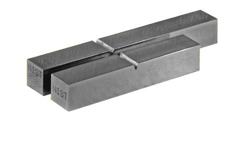
7 SPECIMEN 7
8 Stress = Load / Cross sectional area Strain = Change in length / original length Modulus of Elasticity [E] = stress / strain Percentage elongation of the material gives certain measure of ductility and is measured in standard gauge length and is taken V sa where, sa is the sectional area. INSTRUCTIONS: 1. Sketch the wedge grips used to fix the specimen. 2. Mark the specimen by punch at interval of 10 mm along the length. Distance between grips should be 20 times the diameter. 3. Observe the adjusted loading range and note the same. 4. Fix specimen between grips. 5. Adjust gauge length on extensometer and fix it on middle portion of the bar. Adjust the zero of extensometer and the measuring device of UTM. 6. Switch on the machine, take extensometer readings for the specified intervals and record them. 7. Observe the hesitation [vibration] in movement of load dial and indicator will move somewhat to and fro. Record upper load and lower load at this moment. That gives the upper and lower yield point. 8. Record further extensions on extensometer. The stage from plastic range to ultimate load is known as strain hardening stage. 9. Observe neck formation at ultimate load & main indicator coming back. 10. Record breaking load. Noise is heard of the specimen. Switch of the machine. 11. Remove specimen. It will be hot at the point of fracture. 12. Adjust the cup and cone to rejoin the specimen and find out the final gauge length. Measure final diameter at fracture. 13. If fracture is near the grip, test has to be repeated. OBSERVATIONS: 1. Least count of Extensometer: 2. Actual diameter: 3. Gauge length initial : Final: 4. Distance between grips: 8
9 Observation Table: Sr. No. Load (P) Def. (δ) Stress (σ) Strain (e) Mod. (E) Sr. No. Load (P) Def. (δ) Stress (σ) Strain (e) Mod. (E) 9
10 CALCULATIONS: 1. Stress 2. Strain 3. Percentage elongation 4. Breaking stress 5. Modulus of Elasticity GRAPHS: STRESS vs STRAIN graph upto failure load. Mark the following Points on the graphs: 1. Yield stress. 2. Ultimate stress. 3. Breaking stress. 4. Elastic range. 5. Plastic range. 6. Strain hardening range. CONCLUSION: 10
11 EXPERIMENT NO: DATE: TENSION TEST ON DEFORMED BAR PURPOSE: Deformed bars are twisted bars. They increase the bond between concrete and steel. Now-a-days deformed bars are commonly used in construction. There are different varieties of deformed bars. Tension steel test helps in designing structural members. It also provides a check on quality of deformed bars used. OBJECTIVES: 1. To observe behavior of bar under gradual and uniaxial tension. 2. To plot and interpret stress-strain graphs. 3. To calculate physical properties of specimen. APPARATUS: UTM, weighing balance extensometer, specimen of deformed bar. REFERENCE: Test will be carried out as per IS-1608 and results will be compared with IS THEORY: The deformed bar is not having perfect yield point as that of M.S. therefore, 0.2% proof stress is taken as measure of elastic limit. INSTRUCTIONS: 1. Sketch the wedge grips used to fix the specimen. 2. Mark the specimen by punch at interval of 10 mm along the length. Distance between grips should be 20 times the diameter. 3. Observe the adjusted loading range and note the same. 4. Fix specimen between grips. 5. Adjust gauge length on extensometer and fix it on middle portion of the bar. Adjust the zero of extensometer and the measuring device of UTM. 6. Switch on the machine, take extensometer readings for the specified intervals and record them. 11
12 12
13 7. Observe the hesitation [vibration] in movement of load dial and indicator will move somewhat to and fro. Record upper load and lower load at this moment. That gives the upper and lower yield point. 8. Record further extensions on extensometer. The stage from plastic range to ultimate load is known as strain hardening stage. 9. Observe neck formation at ultimate load & main indicator coming back. 10. Record breaking load. Noise is heard of the specimen. Switch of the machine. 11. Remove specimen. It will be hot at the point of fracture. 12. Adjust the cup and cone to rejoin the specimen and find out the final gauge length. Measure final diameter at fracture. 13. Draw sketch of the specimen showing cup and cone. 14. If fracture is near the grip, test has to be repeated. OBSERVATIONS: 1. Nominal Diameter: 2. Actual Diameter: 3. Gauge Length Initial: Final: 4. Diameter of Specimen: 13
14 Observation Table: Sr. No. Load (P) Def. (δ) Stress (σ) Strain (e) Mod. (E) Sr. No. Load (P) Def. (δ) Stress (σ) Strain (e) Mod. (E) 14
15 GRAPHS: Plot Stress vs Strain. CALCULATIONS: 1. Select a point on graph and note stress and strain. 2. modulus of elasticity: 3. Mark 0.2% strain on the graph and draw a line parallel to the straight line section of the graph. 4. Note down 0.2% proof stress where straight line out stress-strain curve. CONCLUSION: 15
16 EXPERIMENT NO: DATE: IZOD IMPACT TEST ON METALS PURPOSE: Many structural parts or machine parts are subjected to impact loads. Therefore, it is necessary to know resistance of materials to such impact load. The purpose of this test is to find resistance to impact or shock absorbing capacity of materials. OBJECTIVES: 1. To understand principles of impact tests. 2. To determine shock absorbing capacity of materials using IZOD impact test. 3. Compare impact resisting qualities of different materials. REFERENCE: IS / IS APPARATUS: Impact testing machine, standard specimen. PROCEDURE: 1. Raise the pendulum hammer to the required height. Release it allowing a free swing and observe the energy allowable available in the hammer. 2. Raise the pendulum again to the same height as before and clamp it. 3. Fix the specimen in anvil properly. 4. See that nobody is standing in the swinging range of the pendulum. Release the hammer by operating the release mechanism. The specimen breaks and hammer swings to the other side. 5. Observe the energy reading on the scale after breaking the specimen. Note it as final energy reading. 6. Repeat procedure for different specimen materials. 7. Calculate shock absorbing capacity and note it down. 16

17 17
18 OBSERVATIONS: SR. NO. 1 MATERIAL INTERNAL ENERGY (joules) EXTERNAL ENERGY (joules) SHOCK ABSORBER REMARKS 2 3 CONCLUSION: 18
19 EXPERIMENT NO: DATE: CHARPY IMPACT TEST ON METALS PURPOSE: Many structural parts or machine parts are subjected to impact loads. Therefore, it is necessary to know resistance of materials to such impact load. The purpose of this test is to find resistance to impact or shock absorbing capacity of materials. OBJECTIVES: 1. To understand principles of impact tests. 2. To determine shock absorbing capacity of materials using IZOD impact test. 3. Compare impact resisting qualities of different materials. REFERENCE: IS / IS APPARATUS: Impact testing machine, standard specimen. PROCEDURE: 1. Raise the pendulum hammer to the required height. Release it allowing a free swing and observe the energy allowable available in the hammer. 2. Raise the pendulum again to the same height as before and clamp it. 3. Fix the specimen in anvil properly. 4. See that nobody is standing in the swinging range of the pendulum. Release the hammer by operating the release mechanism. The specimen breaks and hammer swings to the other side. 5. Observe the energy reading on the scale after breaking the specimen. Note it as final energy reading. 6. Repeat procedure for different specimen materials. 7. Calculate shock absorbing capacity and note it down. 19
20 20
21 OBSERVATIONS: 1 SR. NO. MATERIAL INITIAL ENERGY (joules) FINAL ENERGY (joules) SHOCK ABSORBER REMARKS 2 3 CONCLUSION: 21
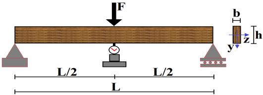
22 EXPERIMENT NO: DATE: FLEXURAL TEST FOR TIMBER PURPOSE: Timber is one of the most widely used materials in traditional structures. The properties of timber vary according to the directions of grains. Members are subjected to axial loads and bending action. It is necessary to understand the behavior of timber in bending. It helps in designing the members. OBJECTIVES: 1. To understand the test procedure. 2. To determine the important properties. REFERENCE: IS 1708 APPARATUS: UTM, bending attachment, scale, verner dial caliper gauge with magnetic base, specimen of mm with grains approximately parallel to its longitudinal edge. THEORY: The effect of the transverse load on the beam is to cause deflection. At any section of the beam, bending moment and shear stresses are developed. Bending stresses, shear stresses and deflection can be easily calculated. When the beam is subjected to central single point load, various characteristic properties will be determined from the following equations 1. Fiber stress at limit of proportionality = 3PL / 2bh 2 2. Equivalent fiber stress at max load = P 1 = 3PL / 2bh 2 3. Shear stress on neutral axis plane at limit of proportionality = 3P / 4bh 4. Modulus of elasticity = PL 3 /4ybh Moment of resistance of beam = fbd 2 / Load at limit of proportionality = 17.5 kn Where, P = Load at limit of proportionality (it is taken as a point on load deflection curve at which graph deviates from the straight line) 22
23 L = Span of test specimen. b = Breadth of test specimen h = Depth of test specimen y = Deflection at limit of proportionality. INSTRUCTIONS: 1. Measure cross sectional dimensions of test specimen and note them. 2. Adjust required span and place specimen on roller supports. 3. Fix the dial gauge below specimen at centre of span. 4. Apply the load at a constant rate and record deflections at interval of 500N. 5. Record load at rupture. 23
24 24
25 OBSERVATIONS: 1. Span of beam = L = 2. Breadth of beam = b = 3. Depth of beam = h = CALCULATIONS: 1. Moment of beam = fbd / 6= 2. Modulus of elasticity, E = PL / 4ybh 3. Moment of max stress = M / Z CONCLUSION: 25
26 EXPERIMENT NO: DATE: FLEXURAL TEST FOR TIMBER (TWO POINT SYSTEM) PURPOSE: Timber is one of the most widely used materials in traditional structures. The properties of timber vary according to the directions of grains. Members are subjected to axial loads and bending action. It is necessary to understand the behavior of timber in bending. It helps in designing the members. OBJECTIVES: 1. To understand the test procedure. 2. To determine the important properties. REFERENCE: IS 1708 APPARATUS: UTM, bending attachment, scale, verner dial caliper gauge with magnetic base, specimen of mm with grains approximately parallel to its longitudinal edge. THEORY: The effect of the transverse load on the beam is to cause deflection. At any section of the beam, bending moment and shear stresses are developed. Bending stresses, shear stresses and deflection can be easily calculated. When the beam is subjected to central single point load, various characteristic properties will be determined from the following equations 1. Fiber stress at limit of proportionality = 3PL / 2bh 2 2. Equivalent fiber stress at max load = P 1 = 3PL / 2bh 2 3. Shear stress on neutral axis plane at limit of proportionality = 3P / 4bh 4. Modulus of elasticity = PL 3 /4ybh Moment of resistance of beam = fbd 2 / 6. 26
27 27
28 INSTRUCTIONS: 1. Measure cross sectional dimensions of test specimen and note them. 2. Adjust required span and place specimen on roller supports. 3. Fix the dial gauge below specimen at centre of span. 4. Apply the load at a constant rate and record deflections at interval of 500N. 5. Record load at rupture. OBSERVATIONS: 1. Span of beam = L = 2. Breadth of beam = b = 3. Depth of beam = h = GRAPH: Plot the graph of load versus deflection. CALCULATIONS: 1. Load at limit of proportionality = 2. Fiber stress = 3. Moment of resistance = 4. Modulus of elasticity = 5. Horizontal shear stress = CONCLUSION: 28
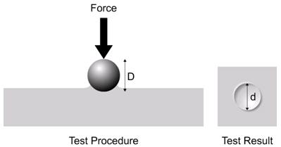
29 EXPERIMENT NO: DATE: BRINELL HARDNESS TEST PURPOSE: Some parts of machinery structure are subjected to constant wearing action by other moving parts. It is necessary to see that these parts have sufficient hardness to resist the wearing action. The purpose of this test is to find the hardness of the given specimen and see if it satisfies the prescribed criteria. OBJECTIVES: 1. To understand principles of Brinell hardness test. 2. To determine Brinell hardness number of different materials. 3. To compare hardness of different materials. APPARATUS: UTM, Brinell ball, indenter attachment, test specimen, microscope. REFERENCE: IS: INSTRUCTIONS: 1. Read the general note on hardness test thoroughly. 2. Prepare the surface of test specimen by smoothening it and remove the oxide scale if any. 3. Select the ball indenter and fix it in the machine. 4. Place the specimen on the test table. 5. Bring the ball indenter near test surface. 6. Before loading see that the indentation is not near to the edge. 7. Calculate the test load. 8. Apply test load gradually. 9. Maintain load at least for 10 seconds and then remove it. 10. Take the specimen out of the machine and measure the diameter of the indentation with a microscope. 11. Repeat the procedure for other specimens and note down the results in observation table. 29
30 30
31 OBSERVATION TABLE: Sr. No. Metal P / D 2 Ball dia (D) Load (P) kg Time (t) sec Indenter dia. BHN CALCULATIONS: BHN = 2P / π D [ D ( D 2 d 2 ) 0.25 RESULT: 31
32 EXPERIMENT NO: DATE: ROCKWELL HARDNESS TEST PURPOSE: Some parts of machinery structure are subjected to constant wearing action by other moving parts. It is necessary to see that these parts have sufficient hardness to resist the wearing action. The purpose of this test is to find the hardness of the given specimen and see if it satisfies the prescribed criteria. OBJECTIVES: 1. To understand principles of Rockwell hardness test. 2. To determine Rockwell hardness number of different materials. 3. To compare hardness of different materials. APPARATUS: UTM, Rockwell ball, indenter attachment, test specimen, microscope. REFERENCE: IS: INSTRUCTIONS: 1. Read the general note on hardness test thoroughly. 2. Prepare the surface of test specimen by smoothening it and remove the oxide scale if any. 3. Select the ball indenter and fix it in the machine. 4. Place the specimen on the test table. 5. Bring the ball indenter near test surface. 6. Before loading see that the indentation is not near to the edge. 7. First a load of 10 kgf is applied and then additional load F1 (140 kgf for cone indenter and 90 kgf for ball indenter) is applied. 8. Maintain load at least for 20 to 25 seconds and then remove it. 9. Take the specimen out of the machine and measure the diameter of the indentation with a microscope. 10. Repeat the procedure for other specimens and note down the results in observation table. 32
33 33
34 OBSERVATION TABLE: Sr. No. Metal P / D 2 Ball dia (D) Load (P) kg Time (t) sec Indentor dia HRN CALCULATIONS: HRN = RESULT: 34
35 EXPERIMENT NO: DATE: SHEAR STRESS ON METALS PURPOSE: This test is carried out to assess the shear stress of the metals which are subjected to shear forces. Rivets and bolts often are used in steel trusses and these are subjected to shear stresses. The design if bolts and rivets is governed by the shear strength of materials of which these are made. Hence, this test is very important. OBJECTIVES: 1. To understand shear failure. 2. To determine shear strength in single shear and double shear. 3. To observe the plane of failure. REFERENCE: IS-5242 (For test procedure) APPARATUS: UTM, shearing attachments with cutters, specimens of different metals, micrometer. INSTRUCTIONS: 1. Measure diameters of given specimen and enter in observation table. 2. Insert specimen through round holes of cutter so as to shear the specimen along two planes. 3. Place shear attachment in machine. 4. Apply load gradually and increase it till failure occurs. 5. Note down load at failure (F). calculate shear strength in double shear as = max load / c.s. area of 2 planes 6. Now take out shear attachments and insert in cutter the holes another cylindrical specimen of previous material, but for single plane shear. 7. Place shear attachment in machine. 8. Apply load gradually and increase it till failure occurs. 9. Note down the load at failure (F 1 ). 10. Repeat procedure 1 to 9 for other metals also. 11. Complete observation table. 35

36 Shear test setup 36
37 OBSERVATION TABLE: SR Specimen Dia Area Single Shear Double shear NO. Metal LOAD STRESS LOAD STRESS CALCULATIONS: Shear stress = load / area RESULT: 37
38 EXPERIMENT NO: DATE: TORSION TEST ON MILD STEEL PURPOSE: Some parts of machines are subjected to angular motion. The angular motion develops twisting moment in the member. Failure of member occurs in different ways. Shear strength of material and modulus of rigidity govern the behavior of material in torsion. This test would enable you to understand the behavior of mild steel and iron under torsion. THEORY: Consider a solid cylindrical shaft fixed at one end and subjected to twisting at the free end as shown. The effect of twisting, changes the position of fibre AB to AB. Angle of twist of free end is BOB = e. Where, T = Torque of twisting moment I p = Polar moment of inertia R s = Ultimate shear stress R = Radius of shaft G = Modulus of rigidity θ = angle of twist in radians. L = length of shaft APPARATUS: UTM with twisting fitment, specimen. PROCEDURE: The length and diameter of the specimen are measured and noted. The specimen is held in grips of torsion twisting machine. One end of specimen is twisted either normally or mechanically. Twisting moments at various instants and corresponding values of angle of twist (Ө) are recorded and modulus of rigidity of the specimen is found G = T L / I p θ 38

39 SPECIMEN 39
40 OBSERVATIONS: Length: L = Diameter: D = Sr. No. Torque (T) θ Angle of twist (radians) Modulus of rigidity (G) CALCULATIONS: RESULT: 40
Strength of Material-I Lab (ME-214-F) LIST OF EXPERIMENTS
 LIST OF EXPERIMENTS") Strength of Material-I Lab (ME-214-F) LIST OF EXPERIMENTS 1.To study the Brinell Hardness testing machine and the Brinell hardness test. 2. To study the Rockwell Hardness testing machine and perform the
Strength of Material-I Lab (ME-214-F) LIST OF EXPERIMENTS 1.To study the Brinell Hardness testing machine and the Brinell hardness test. 2. To study the Rockwell Hardness testing machine and perform the
Dharmapuri LAB MANUAL. Regulation : 2013 Branch. : B.E. Civil Engineering CE6411 STRENGTH OF MATERIALS LABORATORY
 Dharmapuri 636 703 LAB MANUAL Regulation : 2013 Branch Year & Semester : B.E. Civil Engineering : II Year / IV Semester CE6411 STRENGTH OF MATERIALS LABORATORY OBJECTIVE: ANNA UNIVERSITY CE-6411 STRENGTH
EXPERIMENT NO.1 AIM: - OBJECT: - To determined tensile test on a metal. APPRETERS:- THEORY:-
 EXPERIMENT NO.1 AIM: - OBJECT: - APPRETERS:- DIAGRAM:- THEORY:- To determined tensile test on a metal. To conduct a tensile test on a mild steel specimen and determine the following: (i) Limit of proportionality
SIR C.R.REDDY COLLEGE OF ENGINEERING ELURU
 ELURU-534007 STRENGTH OF MATERIALS LABORATORY MANUAL II/IV B.TECH (Mechanical): I SEMESTER DEPARTMENT OF MECHANICAL ENGINEERING DEPARTMENT OF MECHANICAL ENGINEERING STRENGTH OF MATERIALS LAB LIST OF EXPERIMENTS
Properties in Shear. Figure 7c. Figure 7b. Figure 7a
 Properties in Shear Shear stress plays important role in failure of ductile materials as they resist to normal stress by undergoing large plastic deformations, but actually fail by rupturing under shear
MATERIAL TESTING LABORATORY Manual
 MATERIAL TESTING LABORATORY Manual M.Tech/ B.Tech /Diploma, Mechanical Engineering DEPARTMENT OF MECHANICAL ENGINEERING, Indira Gandhi Institute of Technology Sarang, Dhenkanal- 759146,Orissa Compiled
MECHANICAL PROPERTIES AND TESTS. Materials Science
 MECHANICAL PROPERTIES AND TESTS Materials Science Stress Stress is a measure of the intensity of the internal forces acting within a deformable body. Mathematically, it is a measure of the average force
Mechanical behavior of crystalline materials- Comprehensive Behaviour
 Mechanical behavior of crystalline materials- Comprehensive Behaviour In the previous lecture we have considered the behavior of engineering materials under uniaxial tensile loading. In this lecture we
Chapter 4 MECHANICAL PROPERTIES OF MATERIAL. By: Ardiyansyah Syahrom
 Chapter 4 MECHANICAL PROPERTIES OF MATERIAL By: Ardiyansyah Syahrom Chapter 2 STRAIN Department of Applied Mechanics and Design Faculty of Mechanical Engineering Universiti Teknologi Malaysia 1 Expanding
 CE 6411 - STRENGTH OF MATERIALS LABORATORY MANUAL OBSERVATION DEPARTMENT OF CIVIL ENGINEERING NAME:------------------------------------------------------------------------ REGISTER NUMBER:--------------------------------------------------
MECHANICAL PROPERTIES PROPLEM SHEET
 MECHANICAL PROPERTIES PROPLEM SHEET 1. A tensile test uses a test specimen that has a gage length of 50 mm and an area = 200 mm 2. During the test the specimen yields under a load of 98,000 N. The corresponding
P A (1.1) load or stress. elongation or strain
 load or stress. elongation or strain") load or stress MEEN 3145 TENSION TEST - BACKGROUND The tension test is the most important and commonly used test in characterizing properties of engineering materials. This test gives information essential
load or stress MEEN 3145 TENSION TEST - BACKGROUND The tension test is the most important and commonly used test in characterizing properties of engineering materials. This test gives information essential
11/2/2018 7:58 PM. Chapter 6. Mechanical Properties of Metals. Mohammad Suliman Abuhaiba, Ph.D., PE
 1 Chapter 6 Mechanical Properties of Metals 2 Assignment 7, 13, 18, 23, 30, 40, 45, 50, 54 4 th Exam Tuesday 22/11/2018 3 WHY STUDY Mechanical Properties of Metals? How various mechanical properties are
FME201 Solid & Structural Mechanics I Dr.Hussein Jama Office 414
 FME201 Solid & Structural Mechanics I Dr.Hussein Jama Hussein.jama@uobi.ac.ke Office 414 Lecture: Mon 11am -1pm (CELT) Tutorial Tue 12-1pm (E207) 10/1/2013 1 CHAPTER OBJECTIVES Show relationship of stress
MECHANICAL PROPERTIES OF MATERIALS
 MECHANICAL PROPERTIES OF MATERIALS Stress-Strain Relationships Hardness Effect of Temperature on Properties Fluid Properties Viscoelastic Behavior of Polymers Mechanical Properties in Design and Manufacturing
CHENNAI INSTITUTE OF TECHNOLOGY DEPARTMENT OF MECHANICAL ENGINEERING DEPARTMENT OF MECHANICAL ENGINEERING CE6315 STRENGTH OF MATERIALS LAB
 CHENNAI INSTITUTE OF TECHNOLOGY DEPARTMENT OF MECHANICAL ENGINEERING DEPARTMENT OF MECHANICAL ENGINEERING LABORATORY MANUAL CE6315 STRENGTH OF MATERIALS LAB YEAR / SEMESTER : II / IV DEPARTMENT : Mechanical
Page 1 of 46 Exam 1. Exam 1 Past Exam Problems without Solutions NAME: Given Formulae: Law of Cosines: C. Law of Sines:
 NAME: EXAM 1 PAST PROBLEMS WITHOUT SOLUTIONS 100 points Tuesday, September 26, 2017, 7pm to 9:30 You are allowed to use a calculator and drawing equipment, only. Formulae provided 2.5 hour time limit This
True Stress and True Strain
 True Stress and True Strain For engineering stress ( ) and engineering strain ( ), the original (gauge) dimensions of specimen are employed. However, length and cross-sectional area change in plastic region.
MECHANICAL PROPERTIES OF MATERIALS. Manufacturing materials, IE251 Dr M. Eissa
 MECHANICAL PROPERTIES OF MATERIALS, IE251 Dr M. Eissa MECHANICAL PROPERTIES OF MATERIALS 1. Bending Test (Slide 3) 2. Shear Test (Slide 8) 3. Hardness (Slide 14) 4. Effect of Temperature on Properties
CHAPTER 5 FRESH AND HARDENED PROPERTIES OF CONCRETE WITH MANUFACTURED SAND
 61 CHAPTER 5 FRESH AND HARDENED PROPERTIES OF CONCRETE WITH MANUFACTURED SAND 5.1 GENERAL The material properties, mix design of M 20, M 30 and M 40 grades of concrete were discussed in the previous chapter.
UNIT I SIMPLE STRESSES AND STRAINS, STRAIN ENERGY
 SIDDHARTH GROUP OF INSTITUTIONS :: PUTTUR Siddharth Nagar, Narayanavanam Road 517583 QUESTION BANK (DESCRIPTIVE) Subject with Code: Year & Sem: II-B.Tech & I-Sem Course & Branch: B.Tech - ME Regulation:
ME 207 Material Science I
 ME 207 Material Science I Chapter 4 Properties in Bending and Shear Dr. İbrahim H. Yılmaz http://web.adanabtu.edu.tr/iyilmaz Automotive Engineering Adana Science and Technology University Introduction
MECHANICAL PROPERTIES.
 MECHANICAL PROPERTIES. Hardness, strength, ductility and elasticity are among the mechanical properties of a material that would probably first come to mind. In order to know how each of these characteristics
Engineering Materials
 Engineering Materials Mechanical Properties of Engineering Materials Mechanical testing of engineering materials may be carried out for a number of reasons: The tests may simulate the service conditions
CE 221: MECHANICS OF SOLIDS I CHAPTER 3: MECHANICAL PROPERTIES OF MATERIALS
 CE 221: MECHANICS OF SOLIDS I CHAPTER 3: MECHANICAL PROPERTIES OF MATERIALS By Dr. Krisada Chaiyasarn Department of Civil Engineering, Faculty of Engineering Thammasat university Outline Tension and compression
1.103 CIVIL ENGINEERING MATERIALS LABORATORY (1-2-3) Dr. J.T. Germaine Spring 2004 PROPERTIES OF HEAT TREATED STEEL
 Dr. J.T. Germaine Spring 2004 PROPERTIES OF HEAT TREATED STEEL") 1.103 CIVIL ENGINEERING MATERIALS LABORATORY (1-2-3) Dr. J.T. Germaine MIT Spring 2004 Purpose: LABORATORY ASSIGNMENT NUMBER 10 PROPERTIES OF HEAT TREATED STEEL You will learn about: (1) Measurement of
1.103 CIVIL ENGINEERING MATERIALS LABORATORY (1-2-3) Dr. J.T. Germaine MIT Spring 2004 Purpose: LABORATORY ASSIGNMENT NUMBER 10 PROPERTIES OF HEAT TREATED STEEL You will learn about: (1) Measurement of
MECHANICAL PROPERTIES
 MECHANICAL PROPERTIES Mechanical Properties: In the course of operation or use, all the articles and structures are subjected to the action of external forces, which create stresses that inevitably cause
ENGINEERING MATERIAL 100
 Department of Applied Chemistry Division of Science and Engineering SCHOOL OF ENGINEERING ENGINEERING MATERIAL 100 Experiments 4 and 6 Mechanical Testing and Applications of Non-Metals Name: Yasmin Ousam
Tensile/Tension Test Fundamentals
 CIVE.3110 Engineering Materials Laboratory Fall 2016 Tensile/Tension Test Fundamentals Tzuyang Yu Associate Professor, Ph.D. Structural Engineering Research Group (SERG) Department of Civil and Environmental
Material Science & Testing Lab Manual
 Material Science & Testing Lab Manual LAB CODE-RME 351 Prepared by: G L Bajaj Institute of Engineering and Technology Greater Noida- 201306 RME-351 Material Science & Testing Lab List of Experiments Minimum
Welcome to ENR116 Engineering Materials. This lecture summary is part of module 2, Material Properties.
 Welcome to ENR116 Engineering Materials. This lecture summary is part of module 2, Material Properties. 1 2 Mechanical properties. 3 The intended learning outcomes from this lecture summary are that you
BASIC MATERIALS TESTING LABORATORY
 BASIC MATERIALS TESTING LABORATORY INSTRUCTION MANUAL for III Semester B.E. Civil Engineering Testing of Metals, Wood and Burnt Clay Products for their Physical and Mechanical Properties Compiled and Edited
Question Paper Code : 11410
 Reg. No. : Question Paper Code : 11410 B.E./B.Tech. DEGREE EXAMINATION, APRIL/MAY 2011 Fourth Semester Mechanical Engineering ME 2254 STRENGTH OF MATERIALS (Common to Automobile Engineering and Production
BFF1113 Engineering Materials DR. NOOR MAZNI ISMAIL FACULTY OF MANUFACTURING ENGINEERING
 BFF1113 Engineering Materials DR. NOOR MAZNI ISMAIL FACULTY OF MANUFACTURING ENGINEERING Course Guidelines: 1. Introduction to Engineering Materials 2. Bonding and Properties 3. Crystal Structures & Properties
ANNA UNIVERSITY OF TECHNOLOGY - COIMBATORE
 ANNA UNIVERSITY OF TECHNOLOGY - COIMBATORE P.A COLLEGE OF ENGINEERING AND TECHNOLOGY, POLLACHI - 02. DEPARTMENT OF MECHANICAL ENGINEERING YEAR / SEMESTER - II / IV ME 2256 - STRENGTH OF MATERIALS LABORATORY
MECHANICAL TEST FIXTURES
 MECHANICAL TEST FIXTURES Fine Finish Organics Pvt. Ltd. designs and manufactures mechanical test fixtures of the highest quality at affordable prices. Our catalogue includes a broad range of mechanical
MAHATMA GANDHI MISSION S JAWAHARLAL NEHRU ENGINEERING COLLEGE, AURANGABAD. (M.S.)
") MAHATMA GANDHI MISSION S JAWAHARLAL NEHRU ENGINEERING COLLEGE, AURANGABAD. (M.S.) DEPARTMENT OF CIVIL ENGINEERING STREGNTH OF MATERIAL LAB MANUAL Prepared By Prof. V.G.Jadhav Lab In-charge JNEC CIVIL/EE/RAP/015
MAHATMA GANDHI MISSION S JAWAHARLAL NEHRU ENGINEERING COLLEGE, AURANGABAD. (M.S.) DEPARTMENT OF CIVIL ENGINEERING STREGNTH OF MATERIAL LAB MANUAL Prepared By Prof. V.G.Jadhav Lab In-charge JNEC CIVIL/EE/RAP/015
Engineering Materials
 Engineering Materials PREPARED BY Academic Services August 2011 Applied Technology High Schools, 2011 Module Objectives After the completion of this module, the student will be able to: Explain the difference
3. Mechanical Properties of Materials
 3. Mechanical Properties of Materials 3.1 Stress-Strain Relationships 3.2 Hardness 3.3 Effect of Temperature on Properties 3.4 Fluid Properties 3.5 Viscoelastic Properties Importance of Mechanical Properties
 VALLIAMMAI ENGINEERING COLLEGE DEPARTMENT OF MECHANICAL ENGINEERING QUESTION BANK CE 6306 - STRENGTH OF MATERIALS UNIT I STRESS STRAIN DEFORMATION OF SOLIDS PART- A (2 Marks) 1. What is Hooke s Law? 2.
The strength of a material depends on its ability to sustain a load without undue deformation or failure.
 TENSION TEST The strength of a material depends on its ability to sustain a load without undue deformation or failure. This strength is inherent in the material itself and must be determined by experiment.
TI Typical HDPE raw material and pipe test methods EDITION 0607 PAGE 1/10
 PAGE 1/10 Typical HDPE raw material and pipe test methods We hereby want to provide an overview of the most common test methods Index Tests Page Density 2/10 Melt Index 2/10 Tensile Properties 3/10 Flexural
Mechanical Properties of Materials
 INTRODUCTION Mechanical Properties of Materials Many materials, when in service, are subjected to forces or loads, it is necessary to know the characteristics of the material and to design the member from
Chapter Outline Mechanical Properties of Metals How do metals respond to external loads?
 Chapter Outline Mechanical Properties of Metals How do metals respond to external loads?! Stress and Strain " Tension " Compression " Shear " Torsion! Elastic deformation! Plastic Deformation " Yield Strength
Engineering Materials
 Engineering Materials PREPARED BY IAT Curriculum Unit August 2010 Institute of Applied Technology, 2010 Module Objectives After the completion of this module, the student will be able to: Explain the difference
Engineering Materials
 Engineering Materials PREPARED BY Academic Services August 2011 Institute of Applied Technology, 2011 Module Objectives After the completion of this module, the student will be able to: Explain the terms
Mechanical behavior of crystalline materials - Stress Types and Tensile Behaviour
 Mechanical behavior of crystalline materials - Stress Types and Tensile Behaviour 3.1 Introduction Engineering materials are often found to posses good mechanical properties so then they are suitable for
Unit II Shear and Bending in Beams
 Beams and Bending Unit II Shear and Bending in Beams 2 Marks questions and answers 1. Mention the different types of supports. i. Roller support ii. Hinged support iii. Fixed support 2. Differentiate between
ENGR 151: Materials of Engineering LECTURE #12-13: DISLOCATIONS AND STRENGTHENING MECHANISMS
 ENGR 151: Materials of Engineering LECTURE #12-13: DISLOCATIONS AND STRENGTHENING MECHANISMS RECOVERY, RECRYSTALLIZATION, AND GRAIN GROWTH Plastically deforming metal at low temperatures affects physical
Fundamental Course in Mechanical Processing of Materials. Exercises
 Fundamental Course in Mechanical Processing of Materials Exercises 2017 3.2 Consider a material point subject to a plane stress state represented by the following stress tensor, Determine the principal
DE-BONDED DIAGONALLY REINFORCED BEAM FOR GOOD REPAIRABILITY
 13 th World Conference on Earthquake Engineering Vancouver, B.C., Canada August 1-6, 4 Paper No. 3173 DE-BONDED DIAGONALLY REINFORCED BEAM FOR GOOD REPAIRABILITY Kazushi Shimazaki 1 SUMMARY Good repairability
Scientific Seminar Design of Steel and Timber Structures SPbU, May 21, 2015
 Riga Technical University Institute of Structural Engineering and Reconstruction Scientific Seminar The research leading to these results has received the funding from Latvia state research programme under
Code No: R Set No. 1
 Code No: R059210303 Set No. 1 II B.Tech I Semester Regular Examinations, November 2006 MECHANICS OF SOLIDS ( Common to Mechanical Engineering, Mechatronics, Metallurgy & Material Technology, Production
PRESTRESSED CONCRETE STRUCTURES. Amlan K. Sengupta, PhD PE Department of Civil Engineering Indian Institute of Technology Madras
 PRESTRESSED CONCRETE STRUCTURES Amlan K. Sengupta, PhD PE Department of Civil Engineering Indian Institute of Technology Madras Module 5: Analysis and Design for Shear and Torsion Lecture-23: Analysis
Subject with Code: Strength of Materials(16CE104) Course& Branch: B. Tech - CE Year &Sem : II-B. Tech &I-Sem Regulation: R16
 Course& Branch: B. Tech - CE Year &Sem : II-B. Tech &I-Sem Regulation: R16") SIDDHARTH INSTITUTE OF ENGINEERING &TECHNOLOGY:: PUTTUR (Approved by AICTE, New Delhi & Affiliated to JNTUA, Anantapuramu) (Accredited by NBA & Accredited by NAAC with A Grade) (An ISO 9001:2008 Certified
SIDDHARTH INSTITUTE OF ENGINEERING &TECHNOLOGY:: PUTTUR (Approved by AICTE, New Delhi & Affiliated to JNTUA, Anantapuramu) (Accredited by NBA & Accredited by NAAC with A Grade) (An ISO 9001:2008 Certified
sample initial height
 EXPERIMENT 2 NOTCHED BAR IMPACT TESTING OF MATERIALS Background Materials sometimes display brittleness which precludes their use in a given design. Brittleness is characterized by fracturing with low
MECHANICS OF SOLIDS LAB MANUAL
 MECHANICS OF SOLIDS LAB MANUAL Subject Code: Regulations: Class: A30085 R13 JNTUH II Year I Semester (MECH.) Prepared By Prof. U.S.P Rao Mech. Engg. Dept. Mr. A. SOMAIAH Associate Professor (Mech.) Department
ME -215 ENGINEERING MATERIALS AND PROCESES
 ME -215 ENGINEERING MATERIALS AND PROCESES Instructor: Office: MEC325, Tel.: 973-642-7455 E-mail: samardzi@njit.edu PROPERTIES OF MATERIALS Chapter 3 Materials Properties STRUCTURE PERFORMANCE PROCESSING
STRENGTH AND MECHANICS OF MATERIALS ME-303 VIVA QUESTIONS AND ANSWERS
 STRENGTH AND MECHANICS OF MATERIALS ME-303 VIVA QUESTIONS AND ANSWERS 1. Strain is defined as the ratio of (a) change in volume to original volume (b) change in length to original length (c) change in
Chapter 3: Torsion. Chapter 4: Shear and Moment Diagram. Chapter 5: Stresses In beams
 Chapter 3: Torsion Chapter 4: Shear and Moment Diagram Chapter 5: Stresses In beams Torsion Torsion or Torque, T, put simply, is referred to as a twisting moment. θ The derived formulas are: Where: Torsional
Tensile Testing. Objectives
 Laboratory 3 Tensile Testing Objectives Students are required to understand the principle of a uniaxial tensile testing and gain their practices on operating the tensile testing machine to achieve the
FACULTY OF ENGINEERING UNIVERSITY OF MAURITIUS. Mechanical properties of Materials UTOSP 1293 Basics of Metallurgy Prepared by s.
 FACULTY OF ENGINEERING UNIVERSITY OF MAURITIUS Mechanical properties of Materials UTOSP 1293 Basics of Metallurgy Prepared by s. Venkannah MECHANICAL PROPERTIES Engineers are basically concerned with the
STRENGTH OF MATERIALS LAB MANUAL
 STRENGTH OF MATERIALS LAB MANUAL Academic Year : 2017-2018 Course Code : ACE 104 Regulations : IARE R16 Class : IV Semester (CE) Branch : Civil Engineering Department of Civil Engineering INSTITUTE OF
5. A round rod is subjected to an axial force of 10 kn. The diameter of the rod is 1 inch. The engineering stress is (a) MPa (b) 3.
 MPa (b) 3.") The Avogadro's number = 6.02 10 23 1 lb = 4.45 N 1 nm = 10 Å = 10-9 m SE104 Structural Materials Sample Midterm Exam Multiple choice problems (2.5 points each) For each problem, choose one and only one
The Avogadro's number = 6.02 10 23 1 lb = 4.45 N 1 nm = 10 Å = 10-9 m SE104 Structural Materials Sample Midterm Exam Multiple choice problems (2.5 points each) For each problem, choose one and only one
CITY AND GUILDS 9210 Unit 130 MECHANICS OF MACHINES AND STRENGTH OF MATERIALS OUTCOME 1 TUTORIAL 1 - BASIC STRESS AND STRAIN
 CITY AND GUILDS 910 Unit 130 MECHANICS O MACHINES AND STRENGTH O MATERIALS OUTCOME 1 TUTORIAL 1 - BASIC STRESS AND STRAIN Outcome 1 Explain static equilibrium, Newton's laws, and calculation of reaction
5.4 Analysis for Torsion
 5.4 Analysis for Torsion This section covers the following topics. Stresses in an Uncracked Beam Crack Pattern Under Pure Torsion Components of Resistance for Pure Torsion Modes of Failure Effect of Prestressing
PRESTRESSED CONCRETE STRUCTURES. Amlan K. Sengupta, PhD PE Department of Civil Engineering Indian Institute of Technology Madras
 PRESTRESSED CONCRETE STRUCTURES Amlan K. Sengupta, PhD PE Department of Civil Engineering Indian Institute of Technology Madras Module 7: Transmission of Prestress Lecture 30: Pre-tensioned Members Welcome
MACHINES DESIGN SSC-JE STAFF SELECTION COMMISSION MECHANICAL ENGINEERING STUDY MATERIAL MACHINES DESIGN
 1 SSC-JE STAFF SELECTION COMMISSION MECHANICAL ENGINEERING STUDY MATERIAL C O N T E N T 2 1. MACHINE DESIGN 03-21 2. FLEXIBLE MECHANICAL ELEMENTS. 22-34 3. JOURNAL BEARINGS... 35-65 4. CLUTCH AND BRAKES.
Code No: RR Set No. 1
 Code No: RR310305 Set No. 1 III B.Tech I Semester Supplementary Examinations, March 2006 DESIGN OF MACHINE MEMBERS-I ( Common to Mechanical Engineering and Production Engineering) Time: 3 hours Max Marks:
Quiz 1 - Mechanical Properties and Testing Chapters 6 and 8 Callister
 Quiz 1 - Mechanical Properties and Testing Chapters 6 and 8 Callister You need to be able to: Name the properties determined in a tensile test including UTS,.2% offset yield strength, Elastic Modulus,
DESIGN AND ANALYSIS OF STRAIGHTENING MECHANISM FOR COMMERCIAL STEEL BARS
 DESIGN AND ANALYSIS OF STRAIGHTENING MECHANISM FOR COMMERCIAL STEEL BARS Dr. Biju B 1, Dijin JS 2, Anujith C 3, Arun Augustine 4, Mohammad Anas P 5 1Professor, Dept. of Mechanical Engineering, MACE, Kerala,
THE DESIGN AND INSTALLATION OF A FIVE-STORY NEW TIMBER BUILDING IN JAPAN
 THE DESIGN AND INSTALLATION OF A FIVE-STORY NEW TIMBER BUILDING IN JAPAN KOSHIHARA Mikio, Assoc. Prof., Dr.Eng. Institute of Industrial Science, University of Tokyo, Japan, kos@iis.u-tokyo.ac.jp ISODA
بسم الله الرحمن الرحیم. Materials Science. Chapter 7 Mechanical Properties
 بسم الله الرحمن الرحیم Materials Science Chapter 7 Mechanical Properties 1 Mechanical Properties Can be characterized using some quantities: 1. Strength, resistance of materials to (elastic+plastic) deformation;
Belleville Spring. The relation between the load F and the axial deflection y of each disc. Maximum stress induced at the inner edge
 Belleville Spring Disc spring, also called Belleville spring are used where high capacity compression springs must fit into small spaces. Each spring consists of several annular discs that are dished to
When an axial load is applied to a bar, normal stresses are produced on a cross section perpendicular to the axis of the bar.
 11.1 AXIAL STRAIN When an axial load is applied to a bar, normal stresses are produced on a cross section perpendicular to the axis of the bar. In addition, the bar increases in length, as shown: 11.1
1.Axial Force, Shear Force and Bending Moment:
 1 TRIBHUVAN UNIVERSITY INSTITUTE OF ENGINEERING PULCHOWK CAMPUS (Pulchowk, Lalitpur) Subject: Strength of Materials(II/I) (Tutorial ) 1.Axial Force, Shear Force and Bending Moment: 1. Draw AFD, SFD and
Flexural Analysis and Design of Beams. Chapter 3
 Flexural Analysis and Design of Beams Chapter 3 Introduction Fundamental Assumptions Simple case of axial loading Same assumptions and ideal concept apply This chapter includes analysis and design for
3. MECHANICAL PROPERTIES OF STRUCTURAL MATERIALS
 3. MECHANICAL PROPERTIES OF STRUCTURAL MATERIALS Igor Kokcharov 3.1 TENSION TEST The tension test is the most widely used mechanical test. Principal mechanical properties are obtained from the test. There
Reproducible evaluation of material properties. Static Testing Material response to constant loading
 Material Testing Material Testing Reproducible evaluation of material properties Static Testing Material response to constant loading Dynamic Testing Material response to varying loading conditions, including
(a) Pin-Pin P cr = (b) Fixed-Fixed P cr = (d) Fixed-Pin P cr =
 Pin-Pin P cr = (b) Fixed-Fixed P cr = (d) Fixed-Pin P cr =") 1. The most critical consideration in the design of rolled steel columns carrying axial loads is the (a) Percent elongation at yield and the net cross-sectional area (b) Critical bending strength and axial
1. The most critical consideration in the design of rolled steel columns carrying axial loads is the (a) Percent elongation at yield and the net cross-sectional area (b) Critical bending strength and axial
EVALUATION ON SHEAR CAPACITY OF RC BEAMS USING U-SHAPED UFC PERMANENT FORMWORK
 - Technical Paper - EVALUATION ON SHEAR CAPACITY OF RC BEAMS USING U-SHAPED PERMANENT FORMWORK Puvanai WIROJJANAPIROM *1, Koji MATSUMOTO *2, Katsuya KONO *3 and Junichiro NIWA *4 ABSTRACT Shear resistance
Rate Dependency Plastic Modeling
 Rate Dependency Plastic Modeling Hubert Lobo expert material testing CAE material parameters CAE Validation software & infrastructure for materials materials knowledge electronic lab notebooks Considerations
Chapter 7: Mechanical Properties 1- Load 2- Deformation 3- Stress 4- Strain 5- Elastic behavior
 -1-2 -3-4 ( ) -5 ( ) -6-7 -8-9 -10-11 -12 ( ) Chapter 7: Mechanical Properties 1- Load 2- Deformation 3- Stress 4- Strain 5- Elastic behavior 6- Plastic behavior 7- Uniaxial tensile load 8- Bi-axial tensile
Chapter 8: Mechanical Properties of Metals. Elastic Deformation
 Chapter 8: Mechanical Properties of Metals ISSUES TO ADDRESS... Stress and strain: What are they and why are they used instead of load and deformation? Elastic behavior: When loads are small, how much
Reproducible evaluation of material properties. Static Testing Material response to constant loading
 Material Testing Material Testing Reproducible evaluation of material properties Static Testing Material response to constant loading Dynamic Testing Material response to varying loading conditions, including
A H M 531 C The Civil Engineering Center
 Objectives: Measuring the strength of a concrete mix designed at the lab. The strengths to be measured are: Compressive strength. Tensile strength. Flexural strength. Standards: Compressive strength: G.S.
Chapter 6: Mechanical Properties
 Chapter 6: Mechanical Properties ISSUES TO ADDRESS... Stress and strain: What are they and why are they used instead of load and deformation? Elastic behavior: When loads are small, how much deformation
UNIT V PLASTIC ANALYSIS
 SIDDHARTH GROUP OF INSTITUTIONS :: PUTTUR Siddharth Nagar, Narayanavanam Road 517583 QUESTION BANK (DESCRIPTIVE) Subject with Code : SA-II (13A01505) Year & Sem: III-B.Tech & I-Sem Course & Branch: B.Tech
STRESS AND STRAIN AXIAL LOADING
 Chapter 1 STRESS ND STRIN XIL LDING 1.1 INTRDUCTIN The purpose to study the mechanics of materials is to acquire analytical tools necessary for analysis and design of load taking members of practical utility
SOIL MECHANICS CIVIL ENGINEERING VIRTUAL LABORATORY
 SOIL MECHANICS CIVIL ENGINEERING VIRTUAL LABORATORY EXPERIMENT: 10 TRIAXIAL TEST AIM OF THE EXPERIMENT: To find the shear of the soil by Undrained Triaxial Test. APPARATUS REQUIRED: a) Special: i. A constant
CHAPTER 3 - MECHANICAL PROPERTIES. Mechanical properties are the characteristic responses of a material to applied stresses. Selection of mechanical
 CHAPTER 3 - MECHANICAL PROPERTIES Mechanical properties are the characteristic responses of a material to applied stresses. Selection of mechanical tests for a particular application is based primarily
SIDDHARTH GROUP OF INSTITUTIONS :: PUTTUR Siddharth Nagar, Narayanavanam Road QUESTION BANK (DESCRIPTIVE)
") SIDDHARTH GROUP OF INSTITUTIONS :: PUTTUR Siddharth Nagar, Narayanavanam Road 517583 QUESTION BANK (DESCRIPTIVE) Subject with Code :Strength of Materials-II (16CE111) Course & Branch: B.Tech - CE Year
SIDDHARTH GROUP OF INSTITUTIONS :: PUTTUR Siddharth Nagar, Narayanavanam Road 517583 QUESTION BANK (DESCRIPTIVE) Subject with Code :Strength of Materials-II (16CE111) Course & Branch: B.Tech - CE Year
3. TEST METHOD FOR BOND PROPERTIES OF CONTINUOUS FIBER SHEETS TO CONCRETE (JSCE-E )
") 3. TEST METHOD FOR BOND PROPERTIES OF CONTINUOUS FIBER SHEETS TO CONCRETE (JSCE-E 543-2000) 1. Scope This specification describes the method used to test the bond properties to concrete of the continuous
3. TEST METHOD FOR BOND PROPERTIES OF CONTINUOUS FIBER SHEETS TO CONCRETE (JSCE-E 543-2000) 1. Scope This specification describes the method used to test the bond properties to concrete of the continuous
CHAPTER 10: GENERAL STRUCTURAL DETAILS
 CHAPTER 10: GENERAL STRUCTURAL DETAILS 10.1 GENERAL It shall be in accordance with JSCE Standard Specification (Design), 9.1, "steel" shall be taken to signify "steel or CFRM". 10.2 CONCRETE COVER (1)
APPLICATION OF TENSION SOFTENING CURVES TO INVESTIGATE THE SHEAR CARRIED BY FIBERS IN VARIOUS FIBER REINFORCED CONCRETE BEAMS
 III International Conference on Fracture Mechanics of Concrete and Concrete Structures FraMCoS-8 J.G.M. an Mier, G. Ruiz, C. Andrade, R.C. Yu and X.X. Zhang (Eds) APPLICATION OF TENSION SOFTENING CURES
TENSION TEST L 0 = 5.65 S 0 MECHANICAL TESTS BY TENSION TEST IS POSSIBLE TO DETERMINATE THE FOLLOWING MACHANICAL PROPERTIES:
 TENSION TEST This test measuresthe load, applied by mechanical or hydraulic test equipment, necessary to rapture a specimen. The test is performed at room temperature. The specimen properties and the procedures
Method of test for bending moment curvature curve of fiber-reinforced cementitious composites JCI-S
 Japan Concrete Institute Standard Method of test for bending moment curvature curve of fiber-reinforced cementitious composites JCI-S-003-2007 This specification specifies the test method for bending moment
ME 212 EXPERIMENT SHEET #2 TENSILE TESTING OF MATERIALS
 ME 212 EXPERIMENT SHEET #2 TENSILE TESTING OF MATERIALS 1. INTRODUCTION & THEORY The tension test is the most commonly used method to evaluate the mechanical properties of metals. Its main objective is
Code No: R Set No. 1
 Code No: R05310305 Set No. 1 III B.Tech I Semester Regular Examinations, November 2007 DESIGN OF MACHINE MEMBERS-I ( Common to Mechanical Engineering and Production Engineering) Time: 3 hours Max Marks:
Deformation, plastic instability
 Deformation, plastic instability and yield-limited design Engineering Materials 2189101 Department of Metallurgical Engineering Chulalongkorn University http://pioneer.netserv.chula.ac.th/~pchedtha/ Material