MICRO WELD MODEL GP1, GP2 CERAMIC FUSION BUTT WELDERS MICRO PRODUCTS COMPANY SERVICE MANUAL
|
|
|
- Allan Toby Rodgers
- 6 years ago
- Views:
Transcription
1 MICRO WELD MODEL GP1, GP2 CERAMIC FUSION BUTT WELDERS MICRO PRODUCTS COMPANY SERVICE MANUAL 1
2 TABLE OF CONTENTS 1.0 SPECIFICATIONS 2.0 GENERAL OPERATING INSTRUCTIONS 3.0 BASIC OPERATING PARTS 4.0 BASIC OPERATING PARTS LOCATION 5.0 TYPICAL OPERATING SEQUENCE 6.0 SPECIAL ADJUSTMENTS 7.0 PREVENTIVE MAINTENACE 8.0 SUGGESTED SETTINGS 9.0 DIAGNOISTIC CHART FOR TROULBE-SHOOTING 10.0 ELECTRICAL SCHEMATIC 11.0 SAFETY RERMINDERS 12.0 BUYERS GUIDE 13.0 PARTS LIST 1.0 SPECIFICATIONS MODEL GP1 MODEL GP-2 Type of Welding Process Ceramic Fusion Ceramic Fusion Welding Range 20ga to 8ga AWG-Copper 12ga to 4ga AWG-Copper Material Suitability Strand or Bunched Conductor Strand or Bunched Conductor Standard Operating Voltages 115/230 Volts 115/230 Volts Maximum Line Demand 230 Volt duty cycle duty cycle duty cycle duty cycle Maximum Line Demand 115 Volt duty cycle duty cycle duty cycle duty cycle Single Phase AC Transformer 1.5 KVA Maximum 3.0 KVA Maximum Clamp Method Compound Hand Lever Compound Hand Lever Mounting 4-Caster Wheels or Bench 4-Caster Wheels or Bench Dimensions and Weights Height Overall 20 -Bench, 51 -Truck 20 -Bench, 53 ½ Truck Floor or Bench space 9 x 15 Bench Type 24 x 24 Truck Type 9 x 15 Bench Type 30 x 28 ½ Truck Type Welding Die Height 11 Bench Type 42 Truck Type 11 Bench Type 44 ½ Truck Type Weight 170 LBS Bench Type 215 LBS Truck Type 170 LBS Bench Type 215 LBS Truck Type FEATURES OF MICRO-WELD CERAMIC FUSION WELDING EQUIPMENT Micro Weld quality and workmanship Heavy-duty construction & components East to operate controls Low maintenance costs Easy to set welding parameters Safety electrical switch circuits Heavy-duty weld heat selection switch No-upset burr formation during weld process, all strands locked into weld coalescence Sensitive straight slide movable headpiece assembly equipped with ball bearings 2
3 2.0 GENERAL OPERATING INSTRUCIONS 2.1 ELECTRICAL HOOK-UP INSTRUCTIONS First determine that available electrical service in your plant corresponds to the nameplate rating located on welder housing. Electrical wiring to welder must be of sufficient size to deliver full ampere load with no appreciable loss during weld cycle. The welder will not operate properly if there is more than a 10% variation in the line voltage. In general, the welder should be fused with a slow blow fuse of the 100% duty cycle rating. The minimum power cable size to the welder can be obtained by using this same current rating. Refer to National Electrical Code and local electrical regulations for adequate power sizes; disconnect methods and fusing guidelines. Remember line voltages to the welding machine are potentially dangerous should the power cords be damaged or severed. The welding voltages at the welding dies will not harm an operator since they do not exceed 10 volts. 2.2 SAFETY PRECAUTIONS (See section 11.0) ELECTRICAL Maintain electrical cable to welder in good repair. Welder must be grounded and connections securely tightened. Heat Switch must not be changed to new position while a weld cycle is in process. Disconnect electrical service before serving welder high voltages are located within the base of the welder MECHANICAL Operator while using welder must wear safety glasses. Keep all safety guards on welders and use properly. Operators must be instructed on basic operation of unit to prevent injury. Check nameplate rating and keep within material size range for each welder. 2.3 WELDING DIES The dies and shoes supplied with the welder will handle most size and material types within the range of the welder. For new weld applications consult the factory for special die and shoe sets. 3
4 3.0 BASIC OPERATING PARTS 3.1 WELD HEAT SELECTION SWITCH Weld heat is selected by means of a tap switch with 6 steps of voltage. Number one indicates the highest setting and number 6 the lowest. The switch is located on the top left corner of the machine. 3.2 HEAD CLOSED SPACE SETTING This adjustment is made by turning lower socket set screw located below the slide shafts on right end of movable headpiece. 3.3 HEAD OPEN SPACE SETTING This adjustment is made by turning upper socket set screw located below the slide shafts on right end of the movable headpiece. 3.4 LIMIT SWITCH SETTING The weld limit switch controls the cut-off point of current flow to the welding dies. Turning the socket set screw located on the rear slide shaft on the movable headpiece makes this adjustment. 3.5 OPERATING LEVER This lever is actually a cam that sets the open (starting) space then, after the stock is clamped, is turned to activate the weld switch. 3.6 UPSET PRESSURE Upset pressure is required for each weld and is obtained by an internal coil spring. A knurled knob is located on the front slide shaft on the movable headpiece. 3.7 CLAMPING SYSTEM This is a dual system consisting of left and right clamping devices. The welding dies and shoes, the replaceable portion of the clamping mechanism, hold the wire to be joined during the weld cycle. A forward motion of the clamping mechanism facilitates the clamping operation. 4
5 4.0 BASIC OPERATING PARTS LOCATION 5
6 5.0 TYPICAL OPERATING SEQUENCE 5.1 All insulating materials must be removed from conductors where they contact lower welding dies. 5.2 Set weld head selection switch to recommended chart settings. 5.3 Set upset pressure to recommended chart settings. 5.4 Rotate spacing cam to proper chart settings. 5.5 Twist end of conductor in direction of natural lay, pulling outward. 5.6 Carefully square cut conductor end so no individual wires extend beyond cut. Note: Use sharp scissors, because end preparations are important. 5.7 Select correct ceramic sleeve or tool for wire to be welded. 5.8 Thread conductor into ceramic sleeve so that the wire ends are midway through sleeve. Rotating ceramic sleeve in direction of lay will assist threading procedures. 5.9 Clamp preset conductor and sleeve into welding die set, so that the ceramic sleeve is centered between open welding dies Thread other prepared conductor into sleeve and allow the conductor to gently but firmly contact first conductor. Positive contact to wire ends is important for a good weld. Clamp that conductor into welding die Rotate and center ceramic sleeve to assure free movement of conductors during the weld process Rotate spacing lever until it contacts and depresses the operation switch, hold for 1 to 3 seconds to assure a complete weld cycle Unclamp welded conductors and remove ceramic sleeve. Fracture expendable type and disassemble reusable type The inside diameter of ceramic sleeve slightly exceeds the nominal conductor size; therefore the weld zone is lightly larger than conductor diameter An additional sizing operation, swaging, may be required should weld zone exceed tolerances on subsequent processing operations. Micro Products has a special swage tool with exchangeable tooling available to assist with this sizing operation. 6

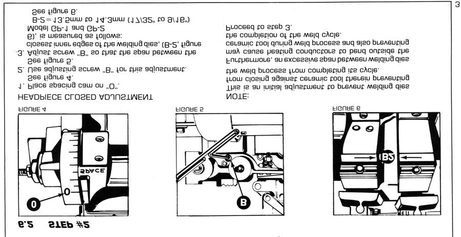
7 6.0 SPECIAL ADJUSTMENTS 7

8 8
9 7.0 PREVENTIVE MAINTENANCE TECHNIQUE Keep in Mind that these welders are precision built to last many years, but will require good maintenance procedures. They are designed to be as automatic as possible with a minimum dependence on the ability of the operator. Adjustments must be made by those thoroughly familiar with the operating principles of the welders. 7.1 WELDING DIE NOTES Welding dies and die shoes in poor condition are the primary caused of bad welds Check die sets for excessive wear and replace if necessary Clean weld die bottoms to remove oxides with emery cloth placed on a flat surface Clean die seats with emery cloth to brighten contact areas After cleaning of dies be sure to wipe off with soft clean cloth Completely tighten dies into seats to assure a good contact Worn die shoes will not hold stock during a weld cycle, change steel faces or replace complete shoes. 7.2 WEEKLY Tighten all loose parts. 7.3 QUARTERLY Repeat above service items Check grease requirements on clamp arms pivot shafts and lubrication points Check anneal parts and replace all worn or broken assemblies Check contacts on magnetic contactor for worn contacts Clean heat switch contacts with low residue cleaner and recoat with petroleum jelly. 7.4 ANNUALLY Repeat previously noted items Check for wear in clap arm pivots Clean inside and outside of welder Check grease requirements on headpiece slide shafts, grease lightly Caution: make sure that power supply is disconnected before servicing welder in anyway! 9
10 7.5 WELDING DIES AND DIE SHOES INFORMATION Description: Welding dies Lower conducting electrode and clamp jaw. Welding die shoes Upper clamping member. Welding dies and die shoes in poor condition are the main causes of bad welds. Care of die sets: Use a brass or fiber blade to remove particles of flashings that build-up on die sets. Excessive flash build-up causes die burns on material and shorting of die sets Do no attempt to clamp material that is not suited for welder into die sets. Undersize materials will slip and burn die grooves, oversize materials will overstress clamping parts Do not use welding die sets for a vise. These parts will not withstand the mechanical abuse Whenever welding dies are replaced, clean bottoms of dies and corresponding die seats to a bright and clean condition before bolting them tightly into place. An oxidized surface will insulate the welding dies and reduce effective welding voltage Welding die shoes must swivel freely within the clamp arm pivots to prevent cracking of die shoes. File down die shoe boss if necessary Welding die set will wear with use and must be changed occasionally for good welding results. Keep and adequate supply of replacement parts available. Wire and rod slippage is a problem caused by poor die sets and a major cause of wire breaks. 10
11 8.0 SUGGESTED SETTINGS RECOMMENDED SETTINGS FOR MODEL GP-1 AND GP-2 MICRO WELD WELDERS STOCK SIZE HEADPIECE OPEN WELD HEAT UPSET PRESSURE MODEL GP-1 20GA Ga 3 ½ Ga Ga 4 ½ 2 3 ½ 12Ga 5 ½ 1 3 ½ 10Ga ½ 9Ga GA ½ MODEL GP-2 12Ga Ga 3 ½ 4 2 ½ 9Ga 3 ½ 4 3 8Ga Ga ½ 4Ga ½ NOTE: These settings are approximate and may be varied to obtain the best weld. 8.1 WELDED STRAND OR BUNCHED COPPER AND ALUMINUM WIRE INDUCTORS Theory: Welds are formed within a ceramic tube or block and no filler materials are needed. Wire ends are resistance heated to a plastic condition and hot forged together within a ceramic tool, which acts as a crucible. The resultant coalescence (weld) locks all single filaments into a solid weld zone Since strand conductors have configuration voids on the faying surfaces, the plastic material normally forced to the outside on a normal weld, is forced into the voids eliminating the upset burr common with standard upset weld. (This type of weld is not suitable for solid wire.) 11
12 8.2 CERAMIC FUSION TECHNIQUE 9.0 DIAGNOSTIC CHART FOR TROUBLE-SHOOTING SERVICE HINTS FOR STRAND CONDUCTOR WELDERS 12
13 Conductors must be able to slide freely within ceramic tools during weld cycle, therefore rotate and move ceramic tool side to side prior to welding. Be sure to center ceramic tool between die sets. Porosity and voids in weld zone may be corrected by using one or more of the following suggestions. 1. Increase upset pressure. 2. Decrease weld heat 3. Readjust timing point of weld heat cut-off, limit switch adjustment, to allow heat to cut-off slightly sooner. 4. Check to make sure conductor is not binding in ceramic tool. 13


14 Amount and length of weld nugget (solid portion of weld) can be varied by one or more of the following suggestions. 1. Increase starting space between die sets when weld nugget is small. 2. Decrease space between die sets when weld nugget is too large. 3. Adjusting limit switch to hold on or cut-off current at a different position. Fracturing of ceramic tools and bent conductors can be corrected by one or more of the following methods. 1. Decrease weld heat to prevent excessive softening of conductors on either side of sleeve. 2. Decrease starting space so as to decrease length of upset and amount of conductor exposed to heat. 3. Decrease upset pressure and still maintain a fused area. 4. A few of the very small stranded and bunched conductors just do not have enough mechanical strength to be processed by this process. 14
15 9.1 ELECTRICAL TROUBLE-SHOOTING OF WELDER (Caution!! Extreme care should be exercised when making these tests. Dangerous voltages are present in the welder. Only persons familiar with electrical safety precautions should perform these tests.) TROUBLE-SHOOTING TABLE (See section 9.1.3) This electrical trouble-shooting table is furnished as a suggested method of trouble-shooting the welder. The individual steps of the table should be performed in the order given, to make the tests valid. The electrical schematic (section 10) furnished for these tests show the table test points. The table may be used for welders with a different but closely related wiring by using corresponding test points. During all tests, line voltage should be connected to L1 & L2 of the welder. The heat switch should be set to the #1 position FINAL ELECTRICAL CHECKS Set the heat switch to the number 1 position, connect the voltmeter across the welding dies. Press the operating switch. The meter reading will typically be less than 10 VAC. Consult the weld specification sheet for this value. Rotate the heat switch through all settings. If the voltage is not read at any setting, the heat switch may be defective. Actuate the weld limit switch; observe the reading goes to zero. Release the weld limit and operating switches, the reading should remain at zero. 15
16 9.1.3 TEST LEAD CONNECTION METER READING PROBLEM IF NO READING PRESS OPERATING SWITCH WELD LIMIT SWITCH ACTUATED 115 VOLT ONLY.USE SCHEMATIC B-5474A.REFERENCE TO L2 FU VAC Bad fuse connection L2 FU VAC Open fuse L2 PB VAC Open wire to operating switch L2 PB VAC Bad operating switch X L2 LS VAC Open wire to weld limit switch X L2 LS VAC Open weld limit switch X L2 CR VAC Open wiring to contactor L2 CR VAC Bad contactor X L2 S VAC Open wire to heat switch X 230 VOLT ONLY.USE SCHEMATIC B-5553A.REFERENCE TO SECTION X1 X2 115 VAC Bad control transformer X2 FU VAC Bad fuse connection X2 FU VAC Open fuse X2 PB VAC Open wire to operating switch X2 PB VAC Bad operating switch X X2 LS VAC Open wire to weld limit switch X X2 LS VAC Open weld limit switch X L2 CR1-1 Line Voltage Open wiring to contactor L2 CR1-2 Line Voltage Bad contactor X L2 S1-1 Line Voltage Open wire to heat switch X NOTE: To perform repair consult section 13 for parts identification. PRESS ANNEAL SWITCH 16
17 17
18 11.0 SAFETY REMINDERS The following accident prevention information is presented to eliminate potential hazards while operating, inspecting or repairing Micro-Weld electric resistance welding equipment. Important safety compliance information for Micro-Weld Welders. GENERAL 1. Qualified personnel, prior to using equipment, must instruct an operator on basic operation and malfunction methods. 2. Safety eyeglasses must be worn by all personnel operating or servicing welders. 3. Use safety equipment properly and keep safety equipment on welders. 4. Determine that both operating voltages and hertz (cycles) of power supply correspond to ratings listed on welder nameplate located on welder housing. 5. Check nameplate ratings and keep within capacities and material categories stated therein. 6. Adjustments or repairs must be made by persons thoroughly familiar with operating principles of welder. 7. Welder must be disconnected from power supply prior to maintenance or repair procedures. ELECTRICAL 1. Refer to National Electrical Code and local regulations for adequate electrical wiring to power welder. Do not operate welder with inadequate electrical power supply cords or cable. 2. All welders must be grounded through power supply and welder ground connection terminal securely tightened. 3. All welders must be able to be disconnected from power source either by a double breaking disconnect switch or unplugged by standard rated plugs. 4. All welders must be fused to prevent injury should an electrical malfunction occur. Welders must never be fused for an ampere load that exceeds the ratings stated on welder nameplate. Normally welders are fused using the nameplate rated load; time lag parameters functional to standard fuses allow this specification. 5. Electric power cords to welder must be kept in good condition. Report any damage or potential hazards to maintenance personnel. 6. The weld heat selection switch, potentiometer or range selection devices must not be changed to a new position while a weld operation is in process. 18
19 12.0 BUYERS GUIDE HOW TO ORDER PARTS: You must provide 1. Machine Model 2. Machine Serial Number 3. Voltage Then identify part(s) on part list (last page in book) and provide MICRO with the circled number. CALL MICRO at OR FAX MICRO at Provide MICRO with your company name and purchase order number. 19
20 G SERIES BUTT WELDERS PARTS LIST GP1,GP2,GS,GT,GC MODEL/ PART NO. DESCRIPTION ITEM # G-01A G-01B Headpiece assembly, stationary and movable Castings, matched machined, with bushings And shields, state for which model req d Headpiece assembly, complete with all Operating parts less welding dies and Die shoes, state for which model required G-04 Bushing, ball bearing,(2) required G-05 Stroke limit screw and nut, nylon G-06 Shield, shaft,(2) required G-17 Limit switch adjusting screw with nylon inserts G-18 Open headpiece adjusting screw with nylon insert G-19 Felt wipes, slide shafts G-30 Spacing cam G-31 Bushing, spacing cam G-32 Stud, space cam mounting G-33 Screw and nut, tension adjusting, nylon G-34 Nut and washer, space cam attaching G-40 Tension spring, models GT,GS and GC GP-40 Tension spring, models GP1 and GP G-41 Worm, tension adjusting G-42 Knob, tension adjusting G-66 Bolt, headpiece to top plate mounting, 4 req d G-140 Guide, wire lift G-141 Screw, wire lift mounting 2 req d G-143 Flashguard with mounting screws G-08L Clamp assembly, complete, left G-08R Clamp assembly, complete, right G-09 Spring, clamp tension G-10 Bolt, nut and washer, clamp mounting, front G-11 Bolt, nut and washer, clamp mounting, rear G-12 Dowel pin, clamp mounting G-13 Grip, handle insulating GT-58V Welding dies,.020 to.150 capacity GS-58V Welding dies,.050 to.128 capacity GC-58V Welding dies,.035 to.225 capacity GP-58R1 Welding dies, radius grooves, 20ga to 14ga GP-58R2 Welding dies, radius grooves, 12ga to 8ga GP-58R3 Welding dies, radius grooves, custom fitted GP-58R4 Welding dies, radius grooves, 6ga to 4ga G-59 Screw, welding die attaching, for models: GT, GS and GC GP-59 Screw, welding dies attaching, for models: GP-1 and GP
21 G SERIES BUTT WELDERS PARTS LIST GP1,GP2,GS,GT,GC MODEL/ PART NO. DESCRIPTION ITEM # G-60T Welding die shoes, pair, tapered For models: GT, GS and GC GP-60F Welding die shoes, pair, tapered For models: GP-1 and GP G-61 Screw, welding die shoe attaching G-50 Slot type anneal jaw, right G-51 Slot type anneal jaw, left G-51A Screws, quick type anneal mounting 4 req d G-52 Screws, quick action type mounting 4 req d G-53 Movable anneal jaw with handle and grip G-54 Spring, anneal jaw tension G-55 Screw, anneal jaw tension adjusting G-56L Stationary anneal jaw, left G-56R Stationary anneal jaw, right G-57L Quick action anneal assembly, complete left G-57R Quick action anneal assembly, complete right G-15 Limit switch G-16 Screw and nut, limit switch mounting G-20 Operating switch G-25 Bracket, limit switch mounting G-26 Screw, limit switch bracket mounting G-27 Cover, limit switch G-28 Screw, cover mounting, 2 required G-80 Tap switch, weld heat selection, 25 amp type G-81 Knob, tap switch, 25 amp type G-82 Number plate, sequence: No 1 thru No G-82A Number plate, sequence: No 1 thru No G-83 Screw, tap switch mounting G-85 Contactor G-90 Power cord, per foot price G-91 Cord grip G-93 Control circuit transformer, 110/120 coil G-138 Lamp assembly, complete G-145 Fuse holder G-146 Fuse G-69 Bushing, transformer secondary insulating G-70GP1 Transformer weld, 120 volts with 6 taps Model GP G-70GP2 Transformer weld, 240 volts with 6 taps Model GP G-70GS Transformer weld, 240 volts with 10 taps Model GS
22 G SERIES BUTT WELDERS PARTS LIST GP1,GP2,GS,GT,GC MODEL/ PART NO. DESCRIPTION ITEM # G-70GC Transformer weld, 240 volts with 10 taps Model GC G-70GT Transformer weld, 120 volts with 10 taps Model GT G-73 Ring, transformer mounting G-74 Long screw and nut, transformer mounting 4 req d G-75 Screw with washer, transformer strap mounting Movable head G-76 Screw with washer, transformer strap mounting Stationary head G-62 Housing assembly, for models: GS, GC and GT GP-62 Housing assembly, for models: GP-1 and GP GP-63 Tray, debris, for models GP-1 and GP GP-64 Anvil, for models GP-1 and GP G-68 Top plate G-150 Caster, swivel G-151 Caster, rigid G-135 Wrenches, T type, welder adjusting G-136 Wrench, allen type, welder adjusting, 1/ G-136 Wrench, allen type, welder adjusting, 3/
23
24 DIES AS LISTED DIES AS LISTED REUSABLE CERAMIC SLEEVE AND CLAMP SCALE FULL D-5460A MODEL GP HEAD PARTS DISPOSABLE CERAMIC SLEEVE SCALE NONE
MICRO PRODUCTS COMPANY MANUFACTURERS OF PRECISION WELDING MACHINES RW 1,2,3,4 RING/BUTT WELDERS SERVICE MANUAL
 MICRO PRODUCTS COMPANY MANUFACTURERS OF PRECISION WELDING MACHINES RW 1,2,3,4 RING/BUTT WELDERS SERVICE MANUAL 1 TABLE OF CONTENTS 1.0 SPECIFICATIONS 2.0 GENERAL HOOK-UP INSTRUCTIONS 3.0 GENERAL OPERATING
MICRO PRODUCTS COMPANY MANUFACTURES OF PRECISION WELDING MACHINES MODEL SEMT FINE WIRE BUTT WELDER SERVICE MANUAL
 MICRO PRODUCTS COMPANY MANUFACTURES OF PRECISION WELDING MACHINES MODEL SEMT FINE WIRE BUTT WELDER SERVICE MANUAL 1 TABLE OF CONTENTS 1.0 SPECIFICATIONS 2.0 GENERAL OPERATING INSTRUCTIONS 3.0 BASIC OPERATING
POWER PINNER BENCH HAND WELDER 7250 OPERATOR S MANUAL
 POWER PINNER BENCH HAND WELDER 7250 OPERATOR S MANUAL Copyright: November 20, 2018 Revised: Serial No. Gripnail Corporation An Employee Owned Company 97 Dexter Road East Providence, Rhode Island 02914-2045
Cutlass Fasteners, Inc. 83 Vermont Ave., Unit 6, Warwick, RI Tel: (401) Fax: (401) cutlass-studwelding.com
 Fax: (401) cutlass-studwelding.com") MODEL : A-58 ARC WELD GUN PART NO. : 602-378A SERIAL NO. : PLEASE READ THIS OPERATION AND MAINTENANCE MANUAL CAREFULLY BEFORE USING YOUR NEW CUTLASS STUD WELDER. COPYRIGHT CFI 2009 email: sales@ PAGE -
MODEL : A-58 ARC WELD GUN PART NO. : 602-378A SERIAL NO. : PLEASE READ THIS OPERATION AND MAINTENANCE MANUAL CAREFULLY BEFORE USING YOUR NEW CUTLASS STUD WELDER. COPYRIGHT CFI 2009 email: sales@ PAGE -
Cutlass Fasteners, Inc. 83 Vermont Ave., Unit 6, Warwick, RI Tel: (401) Fax: (401) cutlass-studwelding.com
 Fax: (401) cutlass-studwelding.com") MODEL : PHM-12 ARC WELD GUN PART NO. : PHM-12 (PHM-12-RS) SERIAL NO. : PLEASE READ THIS OPERATION AND MAINTENANCE MANUAL CAREFULLY BEFORE USING YOUR NEW CUTLASS STUD WELDER. COPYRIGHT CFI 2009 email: sales@
MODEL : PHM-12 ARC WELD GUN PART NO. : PHM-12 (PHM-12-RS) SERIAL NO. : PLEASE READ THIS OPERATION AND MAINTENANCE MANUAL CAREFULLY BEFORE USING YOUR NEW CUTLASS STUD WELDER. COPYRIGHT CFI 2009 email: sales@
USER S OPERATING AND INSTRUCTION MANUAL
 Grand Rapids, Michigan, U.S.A. 49504-5298 USER S OPERATING AND INSTRUCTION MANUAL MODEL 738 MINI CHIP SLICER 0738S20000-CV INDEX Section Description Document No. Page No. SAFETY INSTRUCTIONS --------------------------------------
FW66 FORESTRY WINCH FW66. Owner s Manual 19/02/2016
 FW66 FORESTRY WINCH FW66 19/02/2016 Owner s Manual TABLE OF CONTENTS INTRODUCTION ---------------------------------------------------------------------------------- 2 INTENDED USE -----------------------------------------------------------------------------------
Model: LoLander Series Truck Scale Model: LL FT Model: LL FT Installation, Set-Up and Operation Manual
 SCALE WORKS, INC. Model: LoLander Series Truck Scale Model: LL8035-10FT Model: LL8035-11FT Installation, Set-Up and Operation Manual Cambridge Scale Works, Inc. P.O. Box 670 Honey Brook, PA. 19344 (800)
SUNSTONE WELDERS AC WELDER USER MANUAL
 SUNSTONE WELDERS AC WELDER USER MANUAL 2 Sunstone Welders - AC Welder User Manual TABLE OF CONTENTS Forward... p.4 Introduction... p.5 Welder Setup... p.5 Welder Interface... p.6 Welding Attachments...
READ THIS MANUAL CAREFULLY BEFORE ASSEMBLY, TESTING & OPERATING
 The Operator must thoroughly read and understand this manual before operating the dust collector or commencing any servicing. Care should be taken to follow all safety rules and warning instructions. READ
Model: 770 Light Vehicle Scale Size: 8 x30 x5 Size: 10 x30 x5 Capacity: 40K CLC: 20K Capacity: 60K CLC:30K Installation, Set-Up and Operation Manual
 SCALE WORKS, INC. Model: 770 Light Vehicle Scale Size: 8 x30 x5 Size: 10 x30 x5 Capacity: 40K CLC: 20K Capacity: 60K CLC:30K Installation, Set-Up and Operation Manual Cambridge Scale Works, Inc. P.O. Box
Proweld Equipment Owner & Maintenance Manual FIELD 12 TRENCH (Widos 4900)
") Proweld Equipment Owner & Maintenance Manual FIELD 12 TRENCH (Widos 4900) 35 Green Street, PO Box 653, Malden, MA 02148 Tel: (781) 321-5409 - Fax (781) 321-4421 - Toll Free: (800) 343-3618 www.asahi-america.com
Proweld Equipment Owner & Maintenance Manual FIELD 12 TRENCH (Widos 4900) 35 Green Street, PO Box 653, Malden, MA 02148 Tel: (781) 321-5409 - Fax (781) 321-4421 - Toll Free: (800) 343-3618 www.asahi-america.com
MODEL 185R Kontrol-Karrier Operator s Manual for Morse Kontrol-Karrier
 Contents Page Receiving Procedures.................... 1 Warranty............................. 1 Safety Information..................... 1-2 Machine Description................... 3 Operating Instructions....................
CPT 60 Powerfloat. User & Safety Instructions
 CPT 60 Powerfloat User & Safety Instructions This handbook contains operating and maintenance instructions for the Refina CPT60 Power float Please keep it in a safe place. You may need to refer to it at
Welding Accessories
 Welding Accessories www.airliquide.ca 1-800-817-7697 Welding Accessories BLUESHIELD Welding Cables Blueshield Welding Cables: Excellent flexibility (stays flexible at -50 C) Abrasion resistant Oil, solvent
OPERATOR S MANUAL Model 56A Prefeed / Dereeler
 110 Fairgrounds Drive P.O. Box 188 Manlius, NY 13104-0188 USA 315.682.9176 FAX: 315.682.9160 OPERATOR S MANUAL Model 56A Prefeed / Dereeler PRODUCTION WIRE PROCESSING EQUIPMENT Website: www.carpentermfg.com
ODYSSEY FLOOR MODEL. Owner s Manual. O-6400-F shown rev 118
 Owner s Manual ODYSSEY FLOOR MODEL O-6400-F shown 67-1455 rev 118 3730 E. Southern Avenue, Phoenix, AZ 85040 USA 800-778-8779 Workhorseproducts.com 1 Table of Contents I. Introduction & Safety Information.
FLARING MACHINE MAINTENANCE & INSTRUCTIONS MANUAL. Allswage UK. Roebuck Street, West Bromwich, B70 6RB
 FLARING MACHINE MAINTENANCE & INSTRUCTIONS MANUAL A. WARRANTY AND RESPONSIBILITY Warranty: It's the supplier's responsibility to guarantee the conformity of the product, assuring that it's manufactured
USER S OPERATING AND INSTRUCTION MANUAL
 Grand Rapids, Michigan, U.S.A. 49504-5298 USER S OPERATING AND INSTRUCTION MANUAL MODEL 777-N VARIETY SLICER 0777S20000-CV3 INDEX Section Description Document No. Page No. SAFETY INSTRUCTIONS -------------------------------
11, 000- L b. E x t r e m e - D u t y P a l l e t Tr u c k OWNER S MANUAL
 11, 000- L b. E x t r e m e - D u t y P a l l e t Tr u c k OWNER S MANUAL WARNING: Read carefully and understand all ASSEMBLY AND OPERATION INSTRUCTIONS before operating. Failure to follow the safety rules
2200-Lb. Stacker. Fixed Straddle Leg OWNER S MANUAL
 2200-Lb. Stacker Fixed Straddle Leg OWNER S MANUAL WARNING: Read carefully and understand all ASSEMBLY AND OPERATION INSTRUCTIONS before operating. Failure to follow the safety rules and other basic safety
Operator s Manual for Morse Mobile-Karrier for 55-Gallon Plastic or Steel Drum
 Contents Page Receiving Procedures.................... 1 Warranty............................. 1 Safety Information..................... 1-2 Machine Description................... 3 Operating Instructions....................
Service Manual For the E Ride 26
 Service Manual For the E Ride 26 For: Training Troubleshooting Adjustments Contents 1 Cautions ------------------------------------------------------------------------ 2 Safety Information ----------------------------------------------------------
Operator s Manual for Morse Kontrol-Karrier with Spark Resistant Parts and Air Power Tilt
 Contents Page Receiving Procedures.................... 1 Warranty............................. 1 Safety Information..................... 1-2 Machine Description................... 2 Assembly Instructions..................
Welding & Fabrication Tools Mini VaR Tool Kit
 With Volta Tools You Can Never Go Wrong! Fast and simple belt installation. Unique and versatile design - compact, rugged and easy-to-use. Designed for both shop and field use. Light-weight construction.
General Guidelines. Instructions for Part # WP Safety. It is the user s responsibility to read and follow all instructions.
 General Guidelines It is the user s responsibility to read and follow all instructions. Instructions for Part # WP-48-1000 Keep these instructions with the product at all times and review before each use.
OPERATOR S MANUAL. LINKIT Series LKS300/LKS450 Portable Conveyor. InterQuip USA LLC interquip.net DISTRIBUTED BY: OPERATOR S MANUAL
 OPERATOR S MANUAL LINKIT Series LKS300/LKS450 Portable Conveyor DISTRIBUTED BY: InterQuip USA LLC 203.322.2600 interquip.net 1 IMPORTANT Read, understand and obey these safety rules and operating instructions
TABLE OF CONTENTS. Vacuum Cleaner. Model No. MC-CG Bagless Canister Red North America
 Order No.: MAC1412002CE Vacuum Cleaner Model No. MC-CG902-02 Bagless Canister Red North America TABLE OF CONTENTS PAGE 1 Specifications ----------------------------------------------------- 2 2 Disassembly
Operating Instructions
 Operating Instructions Series B37000 Hose Reels BB37118 L CB37118 L EB37118 L12D BB37122 L CB37122 L EB37122 L12D BB37128 L CB37128 L EB37128 L12D Dimensional Data C A B D Part # A B C D BB/CB37118 L 31
7 PIECE TUBE FLARING KIT
 7 PIECE TUBE FLARING KIT Model 5969 Set up And Operating Instructions Diagrams within this manual may not be drawn proportionally. Due to continuing improvements, actual product may differ slightly from
EU150-EU200-EU400 CRIMPER OPERATORS MANUAL
 EU50-EU00-EU00 CRIMPER OPERATORS MANUAL SAFETY PRECAUTIONS READ INSTRUCTIONS AND IDENTIFY ALL COMPONENT PARTS BEFORE USING CRIMPER KEEP HANDS AWAY FROM PINCH POINTS CONSULT HOSE AND FITTING MANUFACTURER
SERVICE PARTS LIST DEEP CUT BANDSAW D51C BULLETIN NO CATALOG NO SEE PAGE 3 FOR FASTENER TORQUE CHART
 = Part number change from previous service parts list. SPECIFY CATALOG NO. AND SERIAL NO. WHEN ORDERING PARTS DEEP CUT BANDSAW CATALOG NO. 232-20 SERVICE PARTS LIST STARTING SERIAL NO. D5C REVISED BULLETIN
SERVICE PARTS LIST DEEP CUT BANDSAW D51B BULLETIN NO CATALOG NO SEE PAGE 3 FOR FASTENER TORQUE CHART
 = Part number change from previous service parts list. SPECIFY CATALOG NO. AND SERIAL NO. WHEN ORDERING PARTS DEEP CUT BANDSAW CATALOG NO. 232-20 SERVICE PARTS LIST STARTING SERIAL NO. D5B REVISED BULLETIN
INSTRUCTION MANUAL FOR WIRE WELDING MACHINE
 INSTRUCTION MANUAL FOR WIRE WELDING MACHINE IMPORTANT: BEFORE STARTING THE EQUIPMENT, READ THE CONTENTS OF THIS MANUAL, WHICH MUST BE STORED IN A PLACE FAMILIAR TO ALL USERS FOR THE ENTIRE OPERATIVE LIFE-SPAN
DO NOT INSTALL, OPERATE OR SERVICE PRODUCT WITHOUT HAVING READ AND FULLY UNDERSTAND ALL SAFETY PROCEDURES, WARNINGS, INSTALLATION AND OPERATING
 DO NOT INSTALL, OPERATE OR SERVICE PRODUCT WITHOUT HAVING READ AND FULLY UNDERSTAND ALL SAFETY PROCEDURES, WARNINGS, INSTALLATION AND OPERATING INSTRUCTIONS ENCLOSED IN THIS OWNER S MANUAL. 2 SAFETY PROCEDURES
ENel Sp. z o. o. - WROCŁAW DESIGN AND MANUFACTURE OF POWER ELECTRONIC DEVICES INVERTER WELDING MACHINE ENEL250A USER MANUAL DEALER:
 ENel Sp. z o. o. - WROCŁAW DESIGN AND MANUFACTURE OF POWER ELECTRONIC DEVICES INVERTER WELDING MACHINE ENEL250A USER MANUAL DEALER: . INTRODUCTION This manual contains information that will allow to take
Mounting Screw. Channel Filler. Light Angle Adjustable Screw. LED Board Vertical stud and blocking Locking Nose. Driver.
 The Knife Edge Cove is a modular lighting system consisting of two parts: 1- An aluminum fixture housing extrusion 2- Drop-in lighting modules The fixture will provide a continuous knife edge architectural
USER S OPERATING AND INSTRUCTION MANUAL
 Grand Rapids, Michigan, U.S.A. 49504-5298 USER S OPERATING AND INSTRUCTION MANUAL MODEL 619-MDP DOUGH PRESS 0619S20000-CV3 619-MDP DOUGH PRESS INDEX Section Description Document No. Page No. SAFETY INSTRUCTIONS
MODEL , & 797-PB
 Grand Rapids, Michigan, U.S.A. 49504-5298 USER S OPERATING AND INSTRUCTION MANUAL MODEL 797-32, 797-48 & 797-PB BREAD SLICERS 797S20000-C4 INDEX Section Description Document No. Page No. SAFETY INSTRUCTIONS
FOREWORD. Communication on these practices is most welcome. MECHELONIC. The birth of Mechelonic took place a decade ago in January 1972.
 FOREWORD Mechelonic Welders Pvt Ltd This booklet has been prepared by our technical team in order to guide the Industries employing Resistance Welding Technology in their line of manufacture. We have tried
SERVICE PARTS LIST BULLETIN NO M18 FUEL 1-1/2" Magnetic Drill CATALOG NO. G96A
 65(7x) 48 64 CATALOG NO. SERVICE PARTS LIST SPECIFY CATALOG NO. AND SERIAL NO. WHEN ORDERING PARTS M18 FUEL 1-1/2" Magnetic Drill 67 76 2787-059 77 83(3x) STARTING SERIAL NUMBER 79 G96A Torque Chart on
Operation and Maintenance Manual. Joyce/Dayton Metric Screw Jacks
 Joyce/Dayton Corp. Operation and Maintenance Manual Joyce/Dayton Metric Screw Jacks WARNING! The product described in this catalog is for industrial use only. It may not be used to lift or support people
RS2650B ZERO TURN MOWER
 RS2650B ZERO TURN MOWER Published 10/12 PARTS MANUAL SECTION 99 An Operator s Manual was shipped with the equipment. The Operator s Manual is an integral part of the safe operation of this machine and
Operator s Manual for Morse Heavy-Duty Kontrol-Karrier with 3-Piece Drum Holder
 CONTENTS Page Receiving Procedures.................... 1 Warranty............................. 1 Safety Information..................... 1-2 Machine Description................... 3 Operating Instructions....................
PARTS CATALOG 6000/6001 ELITE SERIES SURGICAL TABLES INCLUDING BATTERY MODELS
 PARTS CATALOG 6000/6001 ELITE SERIES SURGICAL TABLES INCLUDING BATTERY MODELS Page i 1. TOP & SIDE FRAME ASSEMBLIES, 6001.... PAGE 2 2. TOP & SIDE FRAME ASSEMBLIES, 6000.... PAGE 6 3. SIDE FRAME & HYDRAULIC
2200-Lb. Semi-Electric Stacker OWNER S MANUAL
 2200-Lb. Semi-Electric Stacker OWNER S MANUAL WARNING: Read carefully and understand all ASSEMBLY AND OPERATION INSTRUCTIONS before operating. Failure to follow the safety rules and other basic safety
WE21S GMA (MIG) Butt Joint With Backing
 Butt Joint With Backing") Uniform Procedures For Collision Repair WE21S GMA (MIG) Butt Joint With Backing 1. Description This procedure describes methods for making and inspecting GMA (MIG) butt joint with backing welds on automotive
Uniform Procedures For Collision Repair WE21S GMA (MIG) Butt Joint With Backing 1. Description This procedure describes methods for making and inspecting GMA (MIG) butt joint with backing welds on automotive
ALUMINUM SCAFFOLDING
 ALUMINUM SCAFFOLDING WARNING: IMPORTANT SAFETY RULES Do not permit anyone to use scaffolds unless he has read and is familiar with these important safety rules. SPECIAL PRECAUTIONS 1. Lock all caster brakes
SERVICE PARTS LIST SPECIFY CATALOG NO. AND SERIAL NO. WHEN ORDERING PARTS. 120V Permanent Magnet Drill STARTING SERIAL NUMBER.
 69(5x) CATALOG NO. SERVICE PARTS LIST SPECIFY CATALOG NO. AND SERIAL NO. WHEN ORDERING PARTS 120V Permanent Magnet Drill 2-20 STARTING SERIAL NUMBER G85A BULLETIN NO. 5-6-00 REVISED BULLETIN DATE Apr.
Service Manual For the E Ride 26
 Service Manual For the E Ride 26 For: Training Troubleshooting Adjustments Rev. 04/2013 Contents 1 Cautions ------------------------------------------------------------------------- Page 4 2 Safety Information
 Instruction Manual Span Scaffolds! W A R N I N G! Before using Instant UpRight Scaffolds, read, understand and follow all Safety Rules, Erection Instructions and Maintenance Rules. Keep this manual for
OPERATION MANUAL. A220 Arc Welding Machine. Serial Number: Where Purchase: Date of purchased:
 OPERATION MANUAL A220 Arc Welding Machine Serial Number: Where Purchase: Date of purchased: CONTENT 1.Safety... 2 2. Summary... 4 3. Electrical principle drawing... 5 4. Specifications... 6 5. Operation
SERVICE PARTS LIST SPECIFY CATALOG NO. AND SERIAL NO. WHEN ORDERING PARTS. M18 FUEL 1-1/2" Linemen Magnetic Drill CATALOG NO. STARTING SERIAL NUMBER
 (7x) 48 4 SERVICE PARTS LIST SPECIFY CATALOG NO. AND SERIAL NO. WHEN ORDERING PARTS M18 FUEL 1-1/2" Linemen Magnetic Drill CATALOG NO. 7 7 2788-20 77 83(3x) STARTING SERIAL NUMBER 144 79 G7A REVISED BULLETIN
AP5K-C Precision AC Double-Pulse Spot Welding Machine User s Manual Shenzhen Will-Best Electronics Co., Ltd
 AP5K-C Precision AC Double-Pulse Spot Welding Machine User s Manual Shenzhen Will-Best Electronics Co., Ltd 1 Content 1. Introduction...3 1.1 Functions...3 1.2 Units of AP5K-C...4 2. The Initial Installation
MODEL 285A-HD Heavy-Duty Forklift-Karrier Operator s Manual for Morse Heavy-Duty Forklift-Karrier Model 285A-HD
 Contents Page Receiving Procedures.................... 1 Warranty............................. 1 Safety Information..................... 1-2 Machine Description................... 3-4 Operating Instructions....................
Instruction Manual Span Scaffolds
 Instruction Manual Span Scaffolds QUALITY & STRENGTH YOU CAN TRUST! W A R N I N G! Before using Instant UpRight Scaffolds, read, understand and follow all Safety Rules, Erection Instructions and Maintenance
BakeMax Dough Mini Moulder BMMDM02
 BakeMax Dough Mini Moulder BMMDM02 2 Instruction Manual 1. Preface ------------------------------------------- P2 2. Machine Introduction -------------------------------- P2 3. Machine Specification and
WE01A GMA (MIG) Plug Weld
 Plug Weld") Uniform Procedures For Collision Repair WE01A GMA (MIG) Plug Weld 1. Description This procedure describes methods for making and evaluating gas metal arc (GMA) plug welds (MIG plug welds) on all types
Uniform Procedures For Collision Repair WE01A GMA (MIG) Plug Weld 1. Description This procedure describes methods for making and evaluating gas metal arc (GMA) plug welds (MIG plug welds) on all types
BUSH HOG LAND MAINTENANCE REPAIR PARTS MANUAL MODELS: HS1736B, HS1742B, HS1836B, HS1842B, HS2036K, HS2042K HOME SERIES ZERO TURN MOWER SECTION: 85
 BUSH HOG LAND MAINTENANCE REPAIR S MANUAL MODELS: HSB, HSB, HSB, HSB, HS0K, HS0K HOME SERIES ZERO TURN MOWER SECTION: 0 Griffin Ave. Selma, AL 0 () -00 Parts Ordering -00-0- Fax -00-- www.bushhog.com OCTOBER,00
Instruction Manual HK285. Note: The Owner/Operator must read carefully and understand all the information presented here before operation.
 Instruction Manual HK285 Note: The Owner/Operator must read carefully and understand all the information presented here before operation. Contents Warnings and Safety Instructions 1 Receiving Instructions
SERVICE PARTS LIST DEEP CUT AC/DC BANDSAW D52C BULLETIN NO CATALOG NO SEE PAGE 3 FOR FASTENER TORQUE CHART
 = Part number change from previous service parts list. SPECIFY CATALOG NO. AND SERIAL NO. WHEN ORDERING PARTS DEEP CUT AC/DC BANDSAW CATALOG NO. 623-20 SERVICE PARTS LIST STARTING SERIAL NO. D2C REVISED
Model 185A Kontrol-Karrier
 Contents Page Receiving Procedures.................... 1 Warranty............................. 1 Safety Information..................... 1-2 Machine Description................... 3 Operating Instructions....................
Dandy Leveler UDLV-150 & UDLV-500 (New Style)
") Owner s Manual Dandy Leveler UDLV-150 & UDLV-500 (New Style) Model # Serial # Southworth Products Corp P.O. Box 1380/Portland, Maine 04104-1380 Phone 800-743-1000 FAX 207-797-4734 www.southworthproducts.com
Owner s Manual Dandy Leveler UDLV-150 & UDLV-500 (New Style) Model # Serial # Southworth Products Corp P.O. Box 1380/Portland, Maine 04104-1380 Phone 800-743-1000 FAX 207-797-4734 www.southworthproducts.com
USER S OPERATING AND INSTRUCTION MANUAL
 Grand Rapids, Michigan, U.S.A. 49504-5298 USER S OPERATING AND INSTRUCTION MANUAL MODEL 619-MDP DOUGH PRESS 0619S20000-CV3 619-MDP DOUGH PRESS INDEX Section Description Document No. Page No. SAFETY INSTRUCTIONS
Single Stacker Operational Manual
 Single Stacker Operational Manual Document #0-0008 //05 TABLE OF CONTENTS I. INTRODUCTION... 4 Compatibility... 4 Validator... 4 Operation... 4 II. INSTALLATION... 5 Front Load Cabinet... 5 Rear Load Cabinet...
SYSTEM 600 BILL CHANGER INSTALLATION INSTRUCTIONS Congratulations...
 www.standardchange.com 1-800-968-6955 Technical Phone Support is from 8:00AM to 7:30PM E.S.T., Monday-Friday Walk-in Service is from 8:00AM to 4:30PM E.S.T., Monday-Friday Parts Department is from 8:00AM
KEEP FOR FUTURE REFERENCE MRT FORKLIFT ADAPTER READ ALL INSTRUCTIONS AND WARNINGS BEFORE USING THIS PRODUCT
 KEEP FOR FUTURE REFERENCE P.O. Box 368 908 West Main Laurel, MT USA 59044 phone 800-548-7341 phone 406-628-8231 fax 406-628-8354 INSTRUCTIONS International Version STOCK NUMBER: 95722 MRT FORKLIFT ADAPTER
OPERATION MANUAL 1.5HP Dust Cyclone
 OPERATION MANUAL 1.5HP Dust Cyclone MODEL NO.: CDC-1090P The Operator must thoroughly Read and understand this Manual before operating the Dust collector or commencing Any servicing. Care should be Taken
MODEL GEK E3 Guard Enclosure Kit. Operator s Manual for Morse Guard Enclosure Kit Model GEK E3 for Can Tumbler Model E3
 Contents Page Receiving Procedures.................... 1 Warranty............................. 1 Safety Information..................... 1-2 Assembly Instructions................... 3-7 Parts List and
MODEL GEK E1 Guard Enclosure Kit. Operator s Manual for Morse Guard Enclosure Kit Model GEK E1 for Can Tumbler Model E1
 Contents Page Receiving Procedures.................... 1 Warranty............................. 1 Safety Information..................... 1-2 Assembly Instructions................... 3-7 Parts List and
HYDRAULIC TRUCK RESTRAINT OWNER S MANUAL
 HYDRAULIC TRUCK RESTRAINT OWNER S MANUAL TR 2000 - TRUCK RESTRAINT Serial Number: Model: Customer: Date Shipped: Options: OWNER S MANUAL Table Of Contents Safety Information Warning... 3 Installation...
GMV Super Star. Part List
 GMV Super Star Part List 25 Table of Contents Part List 25 Magazine... 28 Target Retainer... 30 Throwing Table... 31 Main Frame... 32 Turntable... 33 Base... 34 Elevator... 35 Throwing Arm... 36 Motor...
OPERATION MANUAL. Beam Clamp with Shackle
 Beam Clamp with Shackle OPERATION MANUAL This operation manual is intended as an instruction manual for trained personnel who are in charge of installation, maintenance, repair, etc. Before equipment use,
Replace This With Cover PDF
 Replace This With Cover PDF Read this entire manual before operation begins. Record below the following information which is located on the serial number data plate. Serial No. Model No. Date of Installation
Industrial flue gas probes. Instruction manual
 Industrial flue gas probes Instruction manual 2 1 Contents 1 Contents 1 Contents... 3 2 Safety and the environment... 4 2.1. About this document... 4 2.2. Ensure safety... 4 2.3. Protecting the environment...
TROUBLE SHOOTING TIPS
 Insufficient metal to make weld. Mold does not close tightly causing weld metal to leak out. Handle clamps will not lock closed. Worn mold resulting in leaking weld metal. See image 5 page 287 Wrong size
DISSTON WELDING PRODUCTS TIG/MMA-160/180/200/250D. Welding Machines
 DISSTON WELDING PRODUCTS TIG/MMA-160/180/200/250D Welding Machines FOR SAFE OPERATION: Keep the work area clean. Cluttered work areas invite injuries (indoor and outdoor). Consider the work environment.
Dough Sheeter. Instruction Manual
 Dough Sheeter Item No. 27960 Instruction Manual Version 1 3115 Pepper Mill Court, Mississauga, ON, L5L 4X5 4450 Witmer Industrial Estates, Unit 4, Niagara Falls, NY, 14305 1-800-465-0234 www.omcan.com
78-RK VARIABLE SPEED HEAVY DUTY VIBRATOR OPERATING MANUAL
 78-RK VARIABLE SPEED HEAVY DUTY VIBRATOR OPERATING MANUAL IMPORTANT INSTRUCTIONS WARNING! FOR YOUR SAFETY PLEASE READ INSTRUCTIONS BEFORE OPERATING TOOL & WEAR EYE PROTECTION FD.08/2009 THANK YOU FOR PURCHASING
HIGH MAST CAMERA POLE ASSEMBLY GENERAL
 10-3.24 HIGH MAST CAMERA POLE ASSEMBLY GENERAL The Contractor must furnish and install the following equipment for high mast camera pole assembly as described herein and as shown on the plans: 1. Camera
Edge-of-Dock Leveler 'BA' - 'BX' Series. Owner s Manual and Installation Instructions
 Edge-of-Dock Leveler 'BA' - 'BX' Series Owner s Manual and Installation Instructions A Message to Aaron-Bradley Edge-of-Dock Owners and Operators Edge-of-Docks are specialized equipment with unique operating
TIG Welding Machine. Introduction Risks & Hazards General Safety Operating Safety Maintenance Operating Procedures
 TIG Welding Machine This is a RESTRICTED item in NSW DET schools, where TEACHER USE ONLY is permitted. In VIC DEECD schools, this item can only be used by students under general supervision after the student
MODEL 1308-C & 1308-N
 Walker, Michigan, U.S.A. 49534-7564 USER S OPERATING AND INSTRUCTION MANUAL MODEL 1308-C & 1308-N HEAT SEALER 1308S20000CV1 INDEX Section Description Document No. Page No. DESCRIPTION/SPECIFICATIONS ----------------------------1308S20013
Owner's Manual 3,600 Pound Keeperless Cargo Hook Kit. Eurocopter AS350B3
 Owner's Manual 3,600 Pound Keeperless Cargo Hook Kit on the Eurocopter AS350B3 Part Number 200-281-03 Owner's Manual Number 120-106-02 Revision 0 October 20, 2009 13915 NW 3 rd Court, Vancouver, WA 98685
IMPORTANT. Use of safety surfacing (wood mulch) in compliance with ASTM specification F1292 is required. WARNING
 in compliance with ASTM specification F1292 is required. WARNING") INSTALLATION DETAILS Recommended crew (Adult): 2-3 Installation time: 8-12 Hours not including concrete cure time User age: 5-12 Use zone: 22 Diameter Weight: 990 Actual Dimension: 120 Diameter MAINTENANCE:
INSTALLATION DETAILS Recommended crew (Adult): 2-3 Installation time: 8-12 Hours not including concrete cure time User age: 5-12 Use zone: 22 Diameter Weight: 990 Actual Dimension: 120 Diameter MAINTENANCE:
1.5HP CYCLONE DUST COLLECTOR MANUAL
 1.5HP CYCLONE DUST COLLECTOR MANUAL MANUAL FILTER CLEANING LAGUNA TOOLS 2072 Alton Parkway Irvine, California 92606 Ph: 800.234.1976 www.lagunatools.com 2018, Laguna Tools, Inc. LAGUNA and the LAGUNA Logo
HYDRAULIC DOCK LEVELER OWNERS MANUAL
 HYDRAULIC DOCK LEVELER OWNERS MANUAL 1 HYDRAULIC DOCK LEVELER OWNERS MANUAL 2 TABLE OF CONTENTS Table Of Contents.. Page 2 Koke Hydraulic Leveler Model Information... Page 3 Hydraulic Dock Leveler Installation
High Temperature Aging Cell Instruction Manual
 High Temperature Aging Cell Instruction Manual Part No. 760140001EA Rev. D TABLE OF CONTENTS Section Page Figure 1 General Information... 1 2 Safety Considerations... 3 3 Un-pressurized Testing Procedure...
Model # 940S-P6-BB. 6/7/2017 Page 1 of 10
 Model # 940S-P6-BB 6/7/2017 Page 1 of 10 /7/2017 Page 2 of 10 1675 Locust Street Red Bud, IL 62278 Phone: 618-282-8200 Fax: 618-282-8202 WARRANTY & TERMS WARRANTY: 5 Year Limited Warranty on Thermoplastic
WE11S GMA (MIG) Fillet Weld
 Fillet Weld") Uniform Procedures For Collision Repair WE11S GMA (MIG) Fillet Weld 1. Description This procedure describes methods for making and inspecting GMA (MIG) fillet welds on automotive steel. 2. Purpose The
Uniform Procedures For Collision Repair WE11S GMA (MIG) Fillet Weld 1. Description This procedure describes methods for making and inspecting GMA (MIG) fillet welds on automotive steel. 2. Purpose The
Operating & Maintenance Manual JEC JCP Series. Centrifugal Pumps
 Operating & Maintenance Manual JEC JCP Series Centrifugal Pumps JEC LTD. 408, Cheongyo-ri, Bibong-myun, Hwaseong-si, Gyeonggi-do, South Korea Tel: +82 31 355 0316 Fax: +82 31 355 0319 www.jecpump.com E-mail:
WE01S GMA (MIG) Plug Weld
 Plug Weld") Uniform Procedures For Collision Repair WE01S GMA (MIG) Plug Weld 1. Description This procedure describes methods for making and evaluating GMA (MIG) plug welds on all types of automotive steel. 2. Purpose
Uniform Procedures For Collision Repair WE01S GMA (MIG) Plug Weld 1. Description This procedure describes methods for making and evaluating GMA (MIG) plug welds on all types of automotive steel. 2. Purpose
CA11 11 Column. Operator s Manual. To Purchase This Item, Visit BMI Gaming LIMITED WARRANTY
 LIMITED WARRANTY Seaga warrants to the original purchaser that the equipment is free from defects in material and factory workmanship for a period of one (1) year from date of shipment. Repair or replacement
PS-4045 Adjustable-Height Pallet Stand Use and Maintenance Manual
 Vestil Manufacturing Co. 2999 North Wayne Street, P.O. Box 507, Angola, IN 46703 Telephone: (260) 665-7586 -or- Toll Free (800) 348-0868 Fax: (260) 665-339 http://www.vestilmfg.com/ e-mail: sales@vestil.com
MODEL 185A Kontrol-Karrier
 Contents Page Receiving Procedures.................... 1 Warranty............................. 1 Safety Information..................... 1-2 Machine Description................... 3 Operating Instructions....................
SPECIAL SPECIFICATION 1924 Neighborhood Friendly High Mast Illumination System
 1993 Specifications CSJ 2374-01-154 SPECIAL SPECIFICATION 1924 Neighborhood Friendly High Mast Illumination System 1. Description. This Item shall govern for furnishing and installing the various types
Drag Chain Conveyor Installation and Operation Manual
 Drag Chain Conveyor Installation and Operation Manual Material Handling Equipment Sales, Incorporated 310 S. Section Line Rd Delaware, OH 43015 Phone: (989) 430-4005 Fax: (740) 363-9004 WARRANTY MATERIAL
EU1000 CRIMPER OPERATORS MANUAL WITH ACTTM CONTROLLER
 EU1000 CRIMPER OPERATORS MANUAL WITH ACTTM CONTROLLER SAFETY PRECAUTIONS READ INSTRUCTIONS AND IDENTIFY ALL COMPONENT PARTS BEFORE USING CRIMPER KEEP HANDS AWAY FROM PINCH POINTS CONSULT HOSE AND FITTING
Wealtec Corp. E-Centrifuge Microcentrifuge Operation Manual. Version 3.0 Item # *This instrument is intended for laboratory use only
 Wealtec Corp. E-Centrifuge Microcentrifuge Operation Manual Version 3.0 Item # 03010-1 *This instrument is intended for laboratory use only http://www.wealtec.com E-mail: support@wealtec.com Packing List
Glide-Line Heavy Duty Lift Locate Unit (HLLU)
") V1.0 Glide-Line Heavy Duty Lift Locate Unit (HLLU) Installation & Maintenance Manual Easy Flexible Precise Fast i V1.0 Manual Information Throughout this manual are the following information blocks indicated
V1.0 Glide-Line Heavy Duty Lift Locate Unit (HLLU) Installation & Maintenance Manual Easy Flexible Precise Fast i V1.0 Manual Information Throughout this manual are the following information blocks indicated