INTERFACIAL MODFIFICATION OF MICROCELLULAR CARBON:
|
|
|
- Roy Ball
- 6 years ago
- Views:
Transcription
1 INTERFACIAL MODFIFICATION OF MICROCELLULAR CARBON: INFLUENCE OF CERAMIC AND CARBON NANOTUBE COATINGS A thesis submitted in partial fulfillment of the requirements for the degree of Master of Science in Engineering By ANIL KUMAR KARUMURI B.S., Nagarjuna University, Wright State University
2 WRIGHT STATE UNIVERSITY SCHOOL OF GRADUATE STUDIES December 3, 2009 I HEREBY RECOMMEND THAT THE THESIS PREPARED UNDER MY GUIDANCE BY Anil kumar Karumuri ENTITLED Interfacial Modification of Microcellular Carbon: Influence of Ceramic and Carbon Nanotube Coatings BE ACCEPTED IN PARTIAL FULFILLMENT OF THE REQUIREMENTS FOR THE DEGREE OF Master of Science in Engineering. Sharmila M Mukhopadhyay, Ph.D. Thesis Director Committee on Final Examination Sharmila M Mukhopadhyay, Ph.D. George P G Huang, Ph.D. Department Chair Raghavan Srinivasan, Ph.D. Allen G Jackson, Ph.D. Joseph F Thomas, Jr., Ph.D. Dean, School of Graduate Studies
3 Abstract Karumuri, Anil K., M.S.E., Department of Mechanical and Materials Engineering, Wright State University, Interfacial Modification of Microcellular Carbon: Influence of Ceramic and Carbon Nanotube Coatings. Microcellular carbon is an emerging ultra lightweight and efficient thermal management material, which also has great potential as a reinforcement material for selected composites. However, these porous materials exhibit relatively low mechanical properties, and are susceptible to degradation in oxidizing environment. The scope of this research is to investigate surface modification approaches that can address these issues. Two specific objectives were: (і) to develop ceramic coatings to improve the survivability of carbon foams in high temperature applications, and (іі) to develop and test modifications that can improve cellular composites involving carbon foam. It was seen that a mixed layer of BN and SiC on the foam improves its oxidation resistance at high temperatures to the same extent as pure BN layer. However, the mixed layer had improved microstructure, and presence of silica phase, that maybe useful in development of selected functionally gradient coatings in the future. For modification related to future cellular composites, it was seen that attachment of carbon nanotubes (CNT) on the surface can significantly improve its bonding with other phases, and therefore the mechanical behavior of composites made from this foam. The influence of CNT attachment on mechanical performance and failure mechanics of foam-epoxy composite iii
4 was investigated. Model studies were also carried out on planar graphite-epoxy interfaces using 3-point bending tests. It has been observed that the CNT attachment significantly improves the durability and toughness of the carbon-epoxy interface by preventing delamination. iv
5 Table of Contents 1. Introduction Microcellular Carbon Structures History of Carbon Foams Graphitic Foam Used in this Study Microstructure Analysis of Carbon Foam Surface Coatings Oxidation Protection Coatings Cellular Reinforcement for Composites Geometrical Modeling Hierarchical Structures for Cellular Composites Carbon Nanotubes Grafting for Hierarchical Structures Objectives Literature Microstructure Analysis and Geometrical Modeling Composite Coatings for Oxidation Protection Carbon Foams for Cellular Composites Carbon Nanotube Grafting Characterization Techniques Universal Testing Machine v
6 3.2 Field Emission Scanning Electron Microscopy X-Ray Photoelectron Spectroscopy Oxidation Resistant Coatings Introduction Double Layer Composite Coatings Materials Carbon Foam Substrates Coating Technique as Developed Testing and Results SEM Analysis on Model Flat Graphite XPS Analysis on Model Flat Graphite Cellular Composites Introduction Geometrical Modeling of Carbon Foams Introduction Body Centered Cubic Cell Model Analysis CNT Grafting CNT Grafting on Idealized Model CNT Grafting on Carbon Foams Silicon Oxide Nano-coatings by Plasma Deposition CNT Grafting by Chemical Vapor Deposition (CVD) Preparation of Hybrid Cellular Composite vi
7 5.5 Composite Testing Optimized Samples Results SEM Analysis Role of CNT on Failure Mechanism Interface Characterization Interface Fabrication Experimental Setup Results SEM Analysis Summary and Conclusions References vii
8 List of Figures Figure 1: SEM images of microcellular carbon foam... 4 Figure 2: Carbon nanotube grafting on carbon substrates Figure 3: Instron 4505 universal testing machine Figure 4: JEOL field emission electron microscopy Figure 5: X-ray photoelectron spectroscopy Figure 6: Microstructures of received carbon foams Figure 7: Step wise coating procedure used for double layer composite coating Figure 8: SEM images showing coating morphology after survivability test Figure 9: SEM images showing coating morphology after survivability test Figure 10: General scan of composite coating after survivability test Figure 11: Fine scan of silicon peak Figure 12: Microstructure of carbon foam (top), cross sectional view of solid model (bottom) Figure 13: Idealized representative volume cell (RVC) Figure 14: Specific surface area variation vs. porosity and radius Figure 15: Model representation of grafted CNT on foam Figure 16: 2-Stage chemical vapor deposition furnace Figure 17: Densely grafted CNT at different levels of pores through thickness Figure 18: Vacuum tube to infiltrate the carbon foam with epoxy viii
9 Figure 19: Schematic representation of loading directions in optimized samples Figure 20: Stress-strain behavior of control composite Figure 21: Stress-strain behavior of oxide composite Figure 22: Stress-strain behavior of CNT composite Figure 23: Summarized stress-strain graphs Figure 24: Before compression (1 st row), after compression along the stacks (2 nd row), and across the stacks (3 rd row) Figure 25: Failure mechanism at the junction after the compression test Figure 26: Failure mechanism at the ligament after the compression test Figure 27: Interfacial failure mechanism Figure 28: Interfacial failure mechanism Figure 29: Three point bending test set up Figure 30: Schematic representation of testing method Figure 31: RAW data of three-point-bending test Figure 32: Stress-strain graphs for base interface and CNT reinforced interface Figure 33: Microstructure failure mechanism of control (left) and CNT seam (right) Figure 34: CNT-Epoxy interface failure ix
10 List of Tables Table 1: Classification of coating techniques by deposition rates [4]... 6 Table 2: Coefficient of thermal expansion of prospective barrier materials Table 3: Survivability test results Table 4: Quantification data of the general scan Table 5: Minimum porosities required for interconnection for available models Table 6: Specifications of as-received foam Table 7: Increase in specific surface area of carbon foam with CNT grafting Table 8: Specifications of epoxy resin system Table 9: Strength of control seam, CNT seam, and monolithic graphite x
11 Acknowledgments I would like to start by offering my deepest gratitude to my thesis advisor, Dr. Sharmila M. Mukhopadhyay. Her constant support and guidance were the real driving forces behind this work. The discussions which I had with her really helped me to give a positive outlook to this work. I also thank Dr. Raghavan Srinivasan and Dr. Allen G. Jackson for being on my thesis committee and their constant technical guidance throughout this thesis. This work would not have been possible without the help of my others group members and lab manager Mr. Greg Wilt in particular. A special thanks is due to Ian Barney, Adam Maleszweski, Hema Vijwani, and Beth Maurer for helping me out in preparing this manuscript. Finally, I would like to thank my family members and friends for their constant support and encouragement which I will cherish forever. xi
12 1. Introduction 1.1 Microcellular Carbon Structures The constant demand for light weight, efficient, inexpensive, and multifunctional materials has lead to the development of many cellular structures. Examples of such structures are metallic, ceramic, polymer, and carbon foams. Cellular structures are traditionally divided into two types; closed cell and open cell structures. Closed cell structures consist of non connecting micron size air bubbles embedded inside a solid matrix, whereas open cell structures have interconnected pores distributed three dimensionally at fixed or varying intervals. Among the different open cell structures, carbon structures are of great interest for thermal and structural applications. Carbon foams are microcellular pores interconnected three dimensionally in a regular pattern with porosities ranging from 70 to 96%. Microcellular carbon is classified into two categories; vitreous (glassy) carbon foams and graphitic carbon foams. Vitreous carbon foams are predominately amorphous foams which have lower thermal, electrical, and mechanical properties, because of their lack of graphitization. Graphitic carbon foams have well-aligned graphitic planes along the ligament, which has many properties such as higher mechanical, electrical, thermal properties, and lower coefficient of thermal expansion, etc. Some of the potential applications of graphitic carbon foams are in the field of aerospace, electronics, bio-medical devices, communication satellites, and automobile industry. Many of the applications are primarily due to its low cost, high surface 1
13 area, open cell architecture, low density, controllable thermal and electrical conductivity, energy absorption, low coefficient of thermal expansion, and high corrosion resistance. 1.2 History of Carbon Foams Carbon foam was initially developed by W. Ford in late 60 s [1]. After a few decades, researchers at Wright Patterson Air Force Base (WPAFB) first reported the creation of graphitic foams from mesophase pitch primarily to replace 3-D woven fibers. Several years later, Oak Ridge National Laboratory (ORNL) reported the first foams with specific thermal conductivities higher than that of copper. Later the process was licensed by Koppers Inc. and Poco Graphite Inc. for commercial production. The foams used in this study were developed by ORNL and licensed by Koppers Inc Graphitic Foam Used in this Study Preparation process of the graphitic foam involves the following steps [2]: - Pitch powder is loaded into the cylindrical and rectangular molds. - Loaded molds are evacuated to less than one Torr and then heated to temperatures C above the melting temperature of the pitch. - At this point molds are pressurized to 1500 psi with nitrogen and the temperature of the system is raised to 1500 C at a rate of 5 C/min. - After 15 minutes, the furnace is shutdown and cooled to room temperature at a cooling rate of 1.5 C/min. - At this time pressure is also released at rate of 2 psi/min. - Foams are heated to 1000 C for carbonized and 2800 C for graphitized foam. 2
14 The basic properties of the graphitic foams are: - High thermal conductivity (ligament conductivity is greater than 1700W/m.K) up to 175W/m.K - High specific surface area and low density - Low coefficient of thermal expansion - High acoustical absorption - Good oxidation resistance in inert atmosphere Potential applications include: - Power electronics, brakes and clutch cooling - High temperature structural applications - Possible reinforcing materials for net-shaped composites - Activated carbons for environmental and industrial applications 1.3 Microstructure Analysis of Carbon Foam Microcellular structures are less studied and poorly understood structures compared to traditional carbon structures such as cylindrical fibers, graphite, and carbon nanotubes. Structures such as fibers and graphite have one or two dimensional alignment of graphitic planes, whereas cellular carbon foams are comprised of voids and a solid network consisting of stacked graphitic planes (graphitized foams) oriented along the ligament (Fig 1). Carbon foam nomenclature is explained in Figure 1. Microstructure, physical, chemical, and mechanical properties of carbon foam vary according to the 3


15 Figure 1: SEM images of microcellular carbon foam 4
16 processing parameters, type of precursor pitch, stabilized gasses used, and level of graphitization. Graphitization improves the mechanical strength, density, and thermal conductivity by creating the aligned hexagonal graphitic planes. On the other hand, it also makes the foam brittle, hydrophobic, and susceptible to oxidation. Moreover, as the degree of graphitization increases, properties become anisotropy. The combination of the above effects makes these materials challenging to understand. Many groups have studied the precursor pitch, temperature, and pressure effects on final microstructure of carbon foam using scanning electron microscopy, X-ray diffraction (XRD), and X- ray photoelectron spectroscopy (XPS) [3]. Optimization of strength, thermal conductivity, and graphitization has been done but with limited success. In light of these problems, over the last few years research has been conducted by this group focusing on the development of various surface modification techniques. These include plasma and liquid based coatings, and have proven to be effective in dealing with some of the aforementioned problems. These coatings are based on tailoring the surface chemistry, attaching particles, and growing nanotubes to the cell walls without damaging the underlying graphite. These can help to solve issues related to surface area, surface energies, and chemical potentials. 1.4 Surface Coatings For many engineering applications the chosen materials (carbon foam in this study) may not possess satisfactory surface properties and/or bulk properties. One way to impart or enhance surface related properties is by utilizing coatings which are a form of surface modification. Surface modification can be defined as deliberate process of 5
17 Table 1: Classification of coating techniques by deposition rates [4] 6
18 modifying structures on the outer regions (ragingly from 1nm nm) to enhance or impart the desired properties. Surface modification can be performed by either application of new materials onto the surface (coatings) or modification of composition of existing surface (etching, re-ordering, and alloying). Depending on the substrate material, function, desired durability, and deposition rates of the coating, there are different surface modification techniques available (table 1). Carbon foams have been subjected to various surface modifications techniques over the years for various applications. The application of protective coatings is an approach which dates back to the beginning of civilization. A coating can be defined as layer of any materials used as a cover, protection, decoration or finish. Examples include silicon oxide coatings, fluoro carbon coatings, surface etching, ceramic coatings, and CNT coatings. Most of the techniques used in this thesis are developed in-house and successfully employed on carbon foams. In this thesis, previously explored methods were further developed to make composite ceramic coatings for oxidation protection as discussed in the following section and CNT grafting for hybrid cellular composites to be discussed in later sections. 1.5 Oxidation Protection Coatings Graphitic foams are being considered for high temperature thermal management material due to their combination of properties such as low density, high strength-toweight ratio compared with respect to metallic foams, and their ability to retain mechanical properties at higher temperatures. Although an attractive material, graphitic foam tends to lose these unique properties due its inability to survive in oxidizing environment. 7
19 In this research, a dip-coating technique, developed in this group, has been used. Liquid based ceramic composite coatings have been developed to protect carbon foams from oxidation. A mixture of silicon carbide (SiC) and boron nitride (BN) together with poly-vinyl-pyrrolidone (PVP) binder has been dip coated onto the carbon foams. Performance of the coating was tested by heat treatment test, weight measurements, and referred as survivability of foam. Coating quality was analyzed using scanning electron microscopy (SEM) and surface chemistry is been studied by X-ray photoelectron spectroscopy. 1.6 Cellular Reinforcement for Composites Performance of any composite system mainly depends on two things: characteristics of individual constituents and interfacial properties formed between the constituents. The typical reinforcement material for carbon-polymer composites are cylindrical micron-sized carbon fibers [5] and carbon nanotubes [6]. Carbon fiber reinforced composites possess excellent mechanical and thermal properties along the longitudinal direction, but have poor properties along its transverse direction. A change in properties with respect to direction is called anisotropy which has a significant impact on the performance of the composite. In light of these problems carbon foams have emerged as potential replacement due to their network-type architecture, surface area, isotropic properties, and substantial fiber-like properties. Though the carbon foam itself is a good reinforcement for net-shaped composites, its low density, complex geometry, presence of internal cracks, and graphite-like inert surface chemistry lowers the composite performance. Strength of the carbon foams can be increased by structural texturing such 8
20 as folding of graphitic planes, careful control of composition, and increased degree of graphitization. Graphitization increases the strength, density and specific surface area which is an important parameter for composites. Composite performance often depends on available interfacial contact area between core and matrix, and interfacial shear strength is regarded as directly proportional to this area. Researchers have been trying to optimize graphitization levels and other properties by relating process parameters such as temperature and pressure with porosity, pore sizes, etc. However, these do not help much in terms of overall surface area as seen in the later sections Geometrical Modeling Unlike two dimensional carbon structures such as carbon fibers or graphite, carbon foams have a unique structure which makes it difficult to calculate properties such as strength, conductivities, etc. The open cell architecture, high surface area, low density, and unusual alignment of graphitic planes are features that can be exploited in reinforcing many properties, but are difficult to calculate. Geometrical modeling of carbon foams can help in the prediction of ligament and pore distribution from standard set of geometries. Geometrical modeling may help to correlate the mechanical properties, thermal properties and specific surface area of the foams with the structural parameters such as pore radius, inter-pore diameter and ligament shape. With advancements in computational modeling, researchers have developed various representative volume cells (the smallest shape which will be repeated in three dimensional space to form a cellular network) to model the carbon foam. 9
21 Geometric models such as tetrahedron, cylindrical, and cubic have been developed. Numerical methods such as Finite Element Modeling and Analysis were used to study the deformation characteristics, stress states, and thermal fields of the ligaments [7-8]. In this research, a simple solid geometrical model was enhanced. The body-centered-cubic arrangement of pores [9] initially combines with microstructure to predict a few surface related properties. Secondary electron micrographs and the previously developed analytical model have been combined to estimate changes in bulk properties such as specific surface area and porosity with the change in microscopic properties such as pore radius, inter-pore distance, and representative volume cell (RVC) length. AutoCAD was used to create geometrical models of a representative volume cell (RVC) and model carbon foam. It is predicted from this model, that just changing the parameters (pore size and distribution) of the microcellular foam will not result in drastic changes in surface area. Hence, an additional approach may need to be investigated to enhance these materials. Addition of nano-sized structures to create a hierarchical structure is an option which will be investigated in the preceding section Hierarchical Structures for Cellular Composites One approach common in natural biological systems and natural composites (e.g. cellulose aggregates in wood and collagen aggregates in cartilage) is the use of hierarchical structures. However, this was not done too much on synthetic materials because the challenge of controlling the interface of two dissimilar materials at different 10
22 length scales was found to be formidable. There are some reports of hybrid fibers (fibers grafted with carbon nanotubes) to improve the out-of-plane properties in fiber composites [10] Carbon Nanotubes Grafting for Hierarchical Structures Since the re-discovery of carbon nanotubes (CNT) in early 1990 by Sumio Iijima [11], they have found their way into the many applications including nanotechnology, optics, electronics, and other fields of materials science. A carbon nanotube can be viewed as a cylindrical nanostructure created by rolling a graphene sheet. The typical dimensions (width and length) of CNT changes with processing parameters and raw materials used. CNT have exceptional electrical, mechanical, thermal, chemical, and optical properties mainly due to their high aspect ratio, high surface-area-to-volume, and free electrons, etc [12-13]. CNT have been using in applied fields such as highly efficient field emitters, probes for scanning probe microscopy, high strength nano fibers for high performance composites, and micro-and-nano electronic devices. Because of the wide range of applications it can offer, extensive research has been going on to tailor the CNT growth mechanism to obtain specific kinds such as semi-conducting, conducting for electronic applications, and various shapes for structural applications. Currently there are a number of techniques available to synthesize carbon nanotubes, including arc discharge, laser ablation, and chemical vapor deposition. Among these, chemical vapor deposition (CVD) has proven to be advantageous, because it is able to produce nanotubes in relatively large quantities. Hydrocarbon sources such as methane, ethylene, and xylene 11
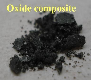
23 are decomposed over Co, Ni, Fe or other transition metal or alloys. Processing steps and parameters are discussed in detail in Chapter 5. A layer of strongly attached CNT can enhance the surface properties (surface area) as well as the bulk properties of the substrate material because CNT offers high surface area, surface roughness, stress transfer channels, and mechanical interlocks needed at the core-matrix interface. There are reports of growing nanotubes on individual fibers, and fiber cloths [10, 14] to make composites (Fig 2). In addition, nanotubes are known for their exceptional load transfer and as an energy absorbing material, which makes them an ideal interface material between reinforcement and matrix in composite applications. Though it is clear that attaching CNT to the cellular core can be an effective way to improve the cellular composite performance, it has never been successfully attempted before. Dr. Mukhopadhyay s group has several publications [15-16] in grafting nanotubes on uneven surfaces such as carbon foams (Fig 2), which opens up the potential usage of the carbon foam for high performance composites. In this research, CVD method has been used for CNT grafting, and CNT-grafted carbon foams are used to make the composites by infiltrating them with epoxy. Epoxy-infiltrated foam is air cured for 10days before being tested. Carbon nanotubes serve both as a load transfer medium between the epoxy matrix and carbon foam by forming a strong interface and also increases the toughness of the carbon foam itself by filling the micro-cracks which are already present. 12


24 Figure 2: Carbon nanotube grafting on carbon substrates 13
25 Developed composites were compression tested and compared with untreated foam composites or control composites. These were also compared with previously proposed pre-coating [17] where the foam was coated with a nano-scale of oxide. This coating with nano-oxide was used as a pre-coating for CNT growth. A side study done earlier [18] had shown that this precoating by itself, without CNT attached, provides some improvement in the foam-epoxy interface. So, here it was considered appropriate to compare all the components: (і) untreated foam (іі) oxide pre-coated foam (ііі) CNT attached foam composites. Each of these structural analyses has been repeated on flat graphite. Highly oriented pyrolytic graphite (HOPG) provides the plane interface for graphite and epoxy which can serve as a quantified model. 1.7 Objectives The motivation for this research is to address the inability of carbon foams to survive high temperatures needed for thermal management, and lack of ductility needed for cellular net shaped composites. For investigating the former issue, a dip coating technique was used to develop composite ceramic coatings to improve survivability of carbon foams from oxidation in open air. For the later problem, methods for enhancing the interface that can enhance ductility of carbon foam for composites have been investigated. It must be emphasized that the focus of this thesis is not to develop one specific composite, but rather to focus on the possibility of creating a specific structure that can improve future composites based on these structures. 14
26 2. Literature There has been a significant amount of research on carbon foam for tailoring the processing parameters, microstructure, and physical properties for specific applications. There is a variety of research papers available on micro structural studies, thermal, and mechanical studies which will be discussed in the following sections. Since this materials inception in 1960, microstructural graphitic carbon has been evaluated as a possible core material for many engineering structures. The time line for evolution of this material can be summarized as follows [1-3]: - In the late 60 s, W. Ford first reported production of vitreous (glassy) carbon foam from thermosetting organic polymer by a simple heat treatment process. - Several decades later, researchers from Sandia National Laboratories first produced the carbon foam from natural precursor. - In the early 90 s researchers from Air Force Research Laboratory (AFRL) and Oak Ridge National Laboratory (ORNL) produced the mesophase pitch derived graphitic foam, specifically to replace 3-D woven fiber for composites and to replace honeycomb primarily for structural composites. - Researcher at ORNL developed inexpensive and high conductivity mesophase pitch derived carbon foams for thermal applications. 15
27 - Poco Graphite Inc. and Koppers Inc. adopted the process for commercial production. Since these are relatively new and complex structures, understanding is some what limited. There are number of unresolved issues accompanied with these structures. Some of these are addressed below: - Similar to other carbon structures such as fibers, graphite, and C/C composites, survivability of the carbon foam is low under oxidizing environments. - Low compatibility with other phases of materials due to surface chemistry related issues. - Not enough structural understanding and relatively low mechanical properties such as strength and work to failure needed for structural applications. - Better correlation between void size, shape, density, porosity, thermal, electrical, and mechanical properties is needed. - Optimization of precursor pitch, process parameters, and final microstructure needed for specific structural and thermal applications. Based on the previous work done by the various groups, some of the issues addressed above were studied, few directly and few indirectly. 16
28 2.1 Microstructure Analysis and Geometrical Modeling Carbon foams are considered to be an ideal alternative material for individual carbon fibers and metallic foams for selected applications. Some of them are reinforcing material for structural composites and core material for sandwich beams respectively. Because many unique properties of the graphitic carbon foam are due to their open cell architecture, alignment of graphitic planes along ligaments, and low density, researchers have been working on gaining control over the final microstructure, bulk thermal and mechanical properties. Some developments are: (і) high thermal conductivity graphitic foams without the traditional blowing, stabilization steps and studied the microstructural changes with the choice of pitch selected and changing processing parameters [3, 19-20]. (іі) Anderson et al from University of Dayton Research laboratory (UDRL) have developed the highest specific strength carbon foams to date from mesophase pitch and studied the density, volume expansion, strength, and thermal conductivities variation with temperature [21-22]. (ііі) there are reports on the anisotropy of these materials in mechanical properties [23-24]. All the above efforts are focused on experimental studies. Researchers are trying to explore computational methods for structure property-process relations. First efforts to establish a solid-bulk property relationship is by Gibson and Ashby [25] followed by Bauer et al. Bauer et al first developed semi-empirical model and studied the thermal conductivity of porous mediums analytically and from that, draw a relation between solid properties to the bulk properties [26]. Balatrapu et al. [27] developed the analytical model consisting of mutually orthogonal cylindrical ligaments to predict the surface area and the thermal conductivity of open cell lattice structures. Sangwook and Roy [8] developed a tetrahedron model to predict the bulk properties of 17
29 the carbon foam finite element analysis on the tetrahedron shaped ligaments and also provided process-property relation. It must be noted that all the above mentioned research was targeted towards achieving optimum conductivity and strength with minimum cost but at the expense of excessive graphitization. However graphitic foams are inert, prone to oxidation, and brittle which needs to be addressed. 2.2 Composite Coatings for Oxidation Protection Like every other carbon structure, graphitic foam is susceptible to oxidation at temperatures above 500 C and loses its unique combination of properties. Formation of refractory ceramic materials such as BN, SiC, Al 2 O 3, Si 3 N 4 or combination may provide some protection needed from surface oxidation. There is a variety of techniques available depending on substrate morphology, chemistry, cost, feasibility, intended application, and function. Some examples are SiC and glass multilayer coatings on C/C composites [28-29], SiO 2 and Al2O 3 coatings on fibers by sol gel technique [30], and SiC coatings by chemical vapor deposition on graphite [31]. However, there is limited research available that targets coatings on carbon foam. Though researchers achieved significant success, the same materials and techniques may not work on carbon foams whose microstructure and morphology is quite different from the above mentioned carbons. James Klett et al. improved the oxidation resistance of the carbon foam by SiC coatings using trichlorsilane as a precursor [32]. This is a complex process involving toxic chemicals. The goal of the present project is to use benign chemicals, simple, and inexpensive processing route. 18
30 An earlier thesis in this group (D. N. Sharma, [33]) involves solution based, simple scalable dip technique for anti-oxidation coatings on carbon foams. The coating consisted of varying sizes of hexagonal BN particles forming a multi layer. This was done by dipping the carbon foam in a BN-containing precursor [33]. Double layer coatings however showed little improvement and issues such as adhesion and oxidation mechanisms were not addressed. In this thesis, some effort was made to advance the process to form a composite multilayer coating containing a mixture of SiC and BN particles. This would help in oxidation resistance and lay the groundwork for creating compositionally (and functionally) gradient coatings in future. 2.3 Carbon Foams for Cellular Composites Cellular materials have distinct advantages over their solid counter parts because of the high specific strength, surface area, low cost, and versatility for selected applications. They are of great interest for reinforcement material in cellular composites and main core material in sandwich beam construction. They may be used in loadcarrying structures and thermal management applications. Microcellular carbon structures can be a preferable choice over their metal counter parts in some cases because they are cheap, light, and versatile. Possibility of carbon foam as a core for sandwich panels has been tested with significant success [34-35]. However carbon foam based cellular composites showed poor mechanical properties because graphitic carbon foam is brittle [36]. Reasons cited are cell wall openings due to the precursor hardening at graphitization temperatures and graphite like surface chemistry which does not form any chemical bonds with the polymer matrix [37]. Enhanced interfacial bonding can be promoted by 19
31 surface etching, surface roughing, and attaching active groups. Earlier researches in this group have developed plasma enhanced silicon oxide coatings to improve core-matrix interfacial bonding with significant success [38-40]. There are reports of adding chopped fibers and clay to suppress the brittle fracture but this met with limited success [41-42]. However, one approach that can be used is the CNT grafting which will be discussed in the following section Carbon Nanotube Grafting Synthesis of carbon nanotubes has been in practice for several years. There are number of techniques available and the choice of a specific technique depends on several factors such as desired yield, substrate morphology, targeted application, etc. Some of the techniques are arc discharge [43], laser vaporization [44], pyrolysis, and chemical vapor deposition [45-46] are successfully employed for wide variety of applications. Among the number of available techniques, chemical vapor deposition has demonstrated several advantages in growing carbon nanotubes. In addition, growth mechanisms are well studied [47-48] which opens up the possibility of hierarchical structures and successfully used for the multifunctional composites as stated earlier. Hierarchical structure is a structure having components of different length scales. Though very common in natural biomaterials, it is not very common in synthetic materials because of the significant difficulties in fabrication [49]. Some of the hierarchical structures reported so far are grafting carbon nanotubes (CNT) on individual micron size fibers [50-51], fiber cloths [52], and/or ceramic fibers [53]. Composites made 20
32 with CNT grafted fibers or Hybrid fibers have shown improved fracture toughness. The reasons cited are improved interfacial bonding through mechanical interlocking, improved load transfer, improved interfacial contact area, and improved interfacial shear strength due to the presence of CNT reinforced matrix at the interface. However, grafting CNT on uneven substrates such as carbon foam is arguably the toughest task, as graphitic carbon foam has significantly more complex morphology. Any composite performance depends on the individual components as well as the interfacial characteristics. Therefore specific surface area available for reinforcementmatrix interface is a very important factor. Hierarchical structures can increase this interfacial area significantly. In this study, an estimate of available specific surface area and its increase with CNT grafting is calculated using pre-developed geometrical models. This model is built upon analytical models developed by previous groups [9] as stated in earlier section. In this study, microstructure of the graphitic foam and its analytical model was combined to predict the specific surface area of the open cell structures. It can be seen that CNT grafting would increase the available specific surface area by three orders of magnitude [13]. Growing CNT layers have been limited to simple geometries. From earlier studies, it was seen that in order to have reliable growth and strongly attached CNT on any geometry, the critical step is the deposition of oxide layer. This was seen to improve catalytic activity [17]. Plasma enhanced silicon oxide nano-layers grown by this group for multifunctional applications have been used as the starting layer for the CNT growth 21
33 [17-18]. The parameters and process for growing carbon nanotubes was also optimized by earlier research [15]. In this thesis, an optimized process for growing carbon nanotubes on uneven surfaces such as carbon foam was used. Knowledge from the mechanical studies on carbon foams, nano composites, and hybrid fiber composites is combined together to study the failure mechanics of CNT grafted carbon foam reinforced cellular composite. The effects of CNT grafting on interfacial mechanics and failure mechanisms of carbon foam reinforced composites or cellular composites have been studied. Further research was carried out by making CNT grafted graphite-epoxy- CNT grafted seam sandwiches for interfacial strength analysis. Three-point-bending test was used since samples were small and brittle and it was not feasible to grip them for tension tests [54]. The results have been compared to strength of the monolithic paralytic graphite tested this way [55]. 22
34 3. Characterization Techniques The various characterization techniques used in this thesis are discussed here. The equipments used were universal testing machine, field emission scanning electron microscope (FESEM), and X-ray photo electron spectroscopy. 3.1 Universal Testing Machine A universal testing machine is a machine used to test various material properties. The machine used in this researc was Instron 4505 series testing machine (Fig 3). Typical testing system consists of machine/test frame, control, and analysis software. Machine test frame consists of load cell and movable frame to measure force and displacement respectively. Load cell interchangeability, transducer recognition, and auto calibration makes this testing machine easy-to-use. There are wide ranges of load cells available ranging from 100kN to 500N (maximum load they can measure). Repeatability of the load cell is ± 0.25% of reading over a range of 0.4% to 100% of its full capacity. System electronics are designed in a way that they provide overload protection by stopping the test at 105% of full scale output. Control frame is to control the frame movement and test. Analysis software is to set the test procedure, parameters, and record the resulting data digitally. 23

35 Figure 3: Instron 4505 universal testing machine 24
36 Two kinds of tests were performed using the universal testing machine: compression and three-point-bending test. Compression test was to test the surface modifications that can improve cellular composites performance. Whereas, three-pointbending test was to test the model interfaces fabricated by attaching two flat graphite sheets with an epoxy. Detailed description of the tests is discussed in their respective sections. 3.2 Field Emission Scanning Electron Microscopy Field emission scanning electron microscope (FESEM) was one of the characterization techniques widely used in this thesis for microstructural failure analysis (Fig 4). Unlike regular SEM, field emission gun employs cold cathode, providing narrower probing beams at low as well as high electron energy. In addition, it has new technologies such as GB (gentle beam) mode for controlling the electrons irradiated from the specimen surface (especially non-conducting samples used in this work). This additional feature coupled with field emission (FE) gun improves spatial resolution while minimizing sample charging and damage. This system consists of four detectors: secondary electron detector, back-scattered electron detector, transmission electron detector, and X-ray detector, in order to acquire maximum information from the specimen. The complete set up is connected to graphical user interface (GUI) using windows based PC host. The FESEM used here is JSM-7401F and its details are (Ref 56): Primary function: surface microstructure, chemical composition 25
37 Source type: cold cathode type, FE electron gun Resolution: 1.4nm at 1kV, 1nm at 15kV Accelerating voltage: 100v to 30kV Magnification: 25 to 1,000,000X Maximum specimen size: maximum diameter is 150mm, optional is 200mm Chemical composition: yes, provides through energy dispersive spectroscopy (EDS) Chemical states: no Other features: back scattered mode, transmission mode 3.3 X-Ray Photoelectron Spectroscopy X-ray photoelectron spectroscope (XPS) was the characterization technique used to study the surface chemistry of the oxidation resistance coatings (Fig 5). It can precisely reveal information about elemental composition, empirical formula, chemical state, and electronic state of the elements that exist with in 10nm from the surface. The XPS works under photoelectric effect. The sample surface is irradiated by X- ray source and knocks the electrons out from the outer shells of the surface atoms. Electronics in the system count the number of electrons coming out and simultaneously 26
38 plotting number of electrons on the Y-axis and binding energies on the X-axis. The quantitative formula of the photoelectric effect is: E k = hυ - E b Here hυ is the energy of the X-ray photon, E k and E b are the kinetic energy and E b binding energy of the escaping electron respectively. The XPS used in this study was Kratos AXIS ULTRA and its characteristics are (Ref 57): Primary function: elemental composition, chemical states, empirical formulas X-ray source: Al monochromatic K-alpha or Mg X-rays Vacuum: below 10-9 to Torr Escape depth: 10nm from surface Sample surface: surface should be considerably flat Sample size limits: 1 1 to 3 3cm Element limitation: every element except hydrogen and helium. 27


39 Figure 4: JEOL field emission electron microscopy Figure 5: X-ray photoelectron spectroscopy 28
40 4. Oxidation Resistant Coatings 4.1 Introduction Cellular structures have distinct advantages over their solid counterparts in high temperature thermal management applications. Among different cellular materials available, graphitic carbon foam is a preferred choice as it has three-dimensional network type architecture, high porosity, high specific surface area, and higher bulk thermal conductivities. Despite numerous advantages of the graphitic carbon foam over the other cellular materials, they are prone to oxidation in open air above 500 C. In order to use this material at high temperature thermal management applications, it is important to protect them from being oxidized. These problems lead to the development of oxidation protection coatings, which are common on other carbon structures such as graphitic fibers, C/C composites, and graphite. The preferred barrier materials are refractory metal oxides such as Al 2 O 3, ZrO 2, carbides, and nitrides. There are number of techniques available such as chemical vapor deposition (CVD), physical vapor deposition, plating (electro and electrolyses plating), sol-gel deposition, sputter deposition, ion implantation, plasma & thermal spraying, etc. However, most of the coatings are developed on simple geometries such as cylindrical fibers, flat graphite, and C/C composites. Moreover, some of the above mentioned techniques involve toxic chemical by products such as BCl 3, high processing temperatures, involve expensive equipment, and also restricted to simple geometries. 29
41 There is very limited research on oxidation resistance coatings on cellular carbon. An in-house developed liquid base dip coating proved to be effective on uneven faces like carbon foam hence it was selected for this research. Advantages include no toxic chemicals involved, affordable, versatile, and compatible for ceramics particles used in this study. Among different materials available, boron nitride and silicon carbide were chosen because they are chemically and thermally stable at high temperatures, structurally similar with graphite (hexagonal BN), and has close coefficient of thermal expansion with the graphite (Table 2). In this thesis, double layer composite coating involving BN and SiC was developed. Material β-sic Al 2 O 3 Y 2 O 3 BN-hexagonal Graphite C.T.E (r.t C) 10-6 /K Table 2: Coefficient of thermal expansion of prospective barrier materials 4.2 Double Layer Composite Coatings Materials Boron nitride (BN) and Silicon carbide (SiC) were selected because of the individual properties they can offer for this kind of coating. Selection of hexagonal BN was based on its structural similarity with graphite and its proven ability to form continuous oxidation resistance barriers. Moreover, BN forms boron carbides on carbon substrates, an oxidation resistance material. Various sizes of BN particles were tried 30
42 initially and selected 0.7μm because they provided less pore free coatings. Silicon carbide is a well known material for oxidation protective coatings due to its excellent mechanical and thermal properties. SiC oxidizes at high temperatures and forms uniform crystalline silicon oxide layers, which, in turn, makes the substrate wet and promotes adhesion between substrate and the barrier material. Moreover, thermally grown crystalline silicon oxide (SiO 2 ) layers also acts as a barrier for oxygen penetration. Smaller sized (compared to BN particles) 0.3μm β-sic particles were selected as they were intended to fill the gaps presented in the BN layer. Together, boron nitride acts as an intermediate layer to provide coherent interfaces with substrate and silicon carbide acts as supplier to form silicon oxide layers. To promote adhesion between substrate, BN, and SiC, poly-vinylpyrrolidone (PVP) was selected as binder. PVP cures during the heating process and was burned off eventually without leaving any unwanted by-products Carbon Foam Substrates Different grades of carbon foams are supplied by Koppers Inc. Three types of carbon foam substrates, partially graphitized (L1a), partially graphitized (L1), and graphitized (D) foams. The microstructures of as-received carbon foams are shown in figure Coating Technique as Developed As-received foams were cut into 5mm cubes and cleaned with methanol to remove loose flakes, carbon powder, and any kind of dust particles associated with them. Cleaned samples were placed on hot plate to dry them. Since this was a liquid based 31


43 Figure 6: Microstructures of received carbon foams 32
44 coating, 0.075g of binder PVP was added to 5ml of methanol to form PVP solution. The coating procedure (Fig 7) and binder compositions used were drawn from earlier thesis. 0.15g of boron nitride micro particles of size 0.7μm and 0.15g of silicon carbide micro particles of size 0.3μm were mixed together and the mixture was added to PVP solution to get PVP-(BN + SiC) dispersion. Cleaned 5mm cube samples were dipped in the dispersion for given amount of time and this process was repeated several times to make sure samples were completely coated with PVP-(BN+SiC) dispersion. Coated samples were then placed in box furnace and raised the temperature to 200 C and kept there for 1hr before it was turned off. Samples were allowed to cool in the furnace overnight. This process allows the PVP to polymerize and settles the coating. Similar procedure was followed for the second layer of coating to get double layer composite coating. It must be noted that, previously developed double layer BN coatings (without SiC) were also repeated on the current foams to evaluate double layer composite coating performance. 4.3 Testing and Results Testing was done in open air for oxidation survivability. Multiple samples (maximum of three) were made and tested. Coated samples were inserted into the furnace at 700 C and heat treated for 1hr. Samples were removed after the 1hr. Samples were weighed before and after the heat treatment and difference in weight over initial weight termed as survivability. As-received or uncoated foam samples of same dimensions were also made and tested as control. Results are tabulated in table 3. Weightbeforetest Weightaftertest % Survivability 100 Weight beforetest 33
45 Figure 7: Step wise coating procedure used for double layer composite coating 34
46 L1a L1 D1 BN+SiC Double layer coating (survivability) Uncoated (%) 23.7±3 29.6±4 85.4±3 Coated (%) 83.7±5 88.2±3 92.6±1 Improvement (%) 253±16 197±25 9±2 BN Double layer coating Uncoated (%) 23.7±3 29.6±4 85.4±3 Coated (%) 80.2±5 85.6±3 91.7±2 Improvement (%) 228±16 189±25 7±2 (survivability) Table 3: Survivability test results 35
47 4.4 SEM Analysis on Model Flat Graphite Coatings were repeated on highly oriented pyrolytic graphite (HOPG) which has similar surface chemistry to as-received carbon foams used in this research. From FESEM images, it was observed that the coating morphology was compact and continuous. However, there was observable porosity present (Fig 8-A, 8-B) because of the burning of the PVP during the heat treatment which releases gases, leaving the pores or pin holes in the coating. Higher magnification images also showed presence of few agglomerates (Fig 9-A) and cracks (Fig 9-B). Widely accepted reason for the agglomerates presence was due to the smaller sized particles and cracks were also expected due to the sudden entry into the 700 C furnace. In summary, there was an observable improvement in the coating microstructure over the pure BN coatings previously developed. This improved microstructure was due to the addition of smaller size SiC particles (0.3μm) used in this current research. This result can serve as a base for developing functionally gradient composite coatings. In addition, survivability tests showed that, current coatings improved the survivability of foams significantly over uncoated foams (Table 3). However, this improvement was equal to or little higher than the improvement by pure BN coatings. This unexpected result was attributed to the pores presented in the current coating which allowed the oxygen to penetrate through the coating and strike the underneath carbon. 36


48 Figure 8: SEM images showing coating morphology after survivability test 37


49 Figure 9: SEM images showing coating morphology after survivability test 38
50 4.5 XPS Analysis on Model Flat Graphite XPS spectrum was taken on the coating to analyze the coating surface chemistry. From the general scan (Fig 10), there was an indication of a few carbon-oxygen products shown by multiple carbon peaks at approximately 284eV possibly from the left over PVP binder. Pure boron nitride was also retained, indicated by both general scan and quantitative data (Table 4). It was also observed that the silicon peak was divided into two sub peaks hence fine scan was taken. Detailed analysis of silicon peak showed (Fig 11) original silicon carbide at 99eV and silicon oxide at 102.9eV. Formation of silicon oxide was due to the oxidation of silicon carbide and should have improved the survivability more than the result yielded. However, it was clear from the earlier studies [18-19] that, only thermally grown crystalline oxide layers can able to prevent the oxygen penetration. Oxides formed at room temperature or at 700 C may not act as prevention barrier. In summary, this coating was pure and presence of oxide phases opened up the other possibilities for future work. 39
51 Figure 10: General scan of composite coating after survivability test Element B1s N1s Si2p-1 Si2p-2 C1s-1 C1s-2 O1s Atomic concentrations (%) Table 4: Quantification data of the general scan Figure 11: Fine scan of silicon peak 40
52 5. Cellular Composites 5.1 Introduction Traditionally carbon fiber reinforced composites are of great interest in fields ranging from spacecrafts to sporting goods. However, individual fibers generally provide strength along its longitudinal direction only. In addition, pitch based carbon fibers are expensive, difficult to make, and developed from mesophase pitch which is the same precursor used for pitch based carbon foams. Carbon foams have graphitic planes folded into rigid shapes within the ligaments making them an excellent reinforcement material for net shaped cellular composites. The strength of the carbon foam (maximum compressive strength reported is approximately 50MPa) is lower compared to carbon fibers, but compares well with other cellular materials such as aluminum foam. Carbon foam is also compatible for densification with other materials such as metals, epoxy, and carbon for structural composites. Carbon foam based cellular composites offer isotropic properties, high strength to weight ratio, high surface area, low coefficient of thermal expansion, and low moisture absorption, etc. However, high strength carbon foam often comes at the expense of excessive graphitization that makes structure brittle and inert. Moreover, graphitization also creates 41
53 internal cracks and anisotropy. All the aforementioned problems decrease the performance of the carbon foam based composites. Two of the important factors that influence the composite performance are: Interfacial bonding between constituent materials and available contact area at the interface. An interfacial modification of carbon foam was done with considerable success [17-18]. In this thesis, it was found that CNT grafting was an ideal approach as it increases interfacial surface area. There are models to estimate the surface area which will be discussed in the following section. 5.2 Geometrical Modeling of Carbon Foams Introduction Carbon foam is a mixture of gas pores and continuous solid graphite. Porosity is the ratio of gas pores volume to the volume occupied by the solid graphite and often controls the final microstructure and properties such as surface area, density, thermal and electrical conductivities, and mechanical strength. Many attempts have been made to correlate the microscopic properties such as pore radius and inter pore distance with processing parameters to optimize the carbon foam without compromising the structural integrity of open cell architecture. Examples of such kind of efforts are solid geometrical modeling. Though the real microstructure has pores with uneven size and shape, most of the geometrical models assume uniform spherical pores distributed periodically over a set 42
54 distance. In this thesis, previously developed model was studied to estimate the specific surface area and how it varies with varying pore size and distribution. Among the different models available, body centered cubic cell arrangement was selected because minimum porosity required for inter-connected network of this model was close to minimum open porosity of as-received foams (L1) (Table 5). Moreover, microstructure of as-received foam (L1a) was also similar to the cross sectional view of modeled foam developed using solid works (Fig 12). It must be noted that open porosities of as-received foams were estimates given by Koppers Inc (company who supplied the foams) and any future changes are completely subjected to the supplier. 43
55 Model/cell Body Tetrahedron Face centered Hexagonal centered close packed Minimum porosity for interconnection Table 5: Minimum porosities required for interconnection for available models Foam L1a L1 D1 Density (g/cc) Pore diameter (μm) Porosity (Supplied) Table 6: Specifications of as-received foam 44
 45")
56 Figure 12: Microstructure of carbon foam (top), cross sectional view of solid model (bottom) 45
57 5.2.2 Body Centered Cubic Cell Model The distribution and size of the pores in the real foam may be irregular, i.e., they may not follow any three-dimensional regular arrangement. This irregular arrangement makes surface area calculations difficult. To simplify the problem, a few basic assumptions were made. Assumption 1: All the pores were assumed to have equal diameter. Assumption 2: Each pore was separated by a set distance A representative volume cell (RVC) was (Fig 13) modeled based on the assumptions stated and body centered cell (BCC) arrangement [9]. If the minimum distance between two pores is less than the sum of the radius of two pores (d < 2R p ) then the pores intersect each other and form an open cell network. Let us assume a = Length of the cube edge R p = Radius of the pores h = Height of the spherical cap d = Minimum distance between the pores In this kind of arrangement the distance (d) between the center pore to corner pore is equal to the half of the length of the diagonal hence d a 3 / 2 Volume of the voids Porosity ( P) Eq(1) Total volume 4 Volumeof the voids 2 R 3 p 8V lens...eq (2) 3 = 8 R 3 p V lens 3 46

58 Figure 13: Idealized representative volume cell (RVC) 47
59 Volume of the spherical cap h 3 2 (3R p h) Lens is formed by the two Spherical caps V lens = 2 Vol. of the Spherical hollow cap = 2 2 h (3R p h) 3..Eq (3) Substitute Eq. (3) in equation 2 After some mathematical manipulations, one obtains P = 2 12R 3 2 p d 12R a 3 3 p d Eq (4) Equation valid only for 0.68<P<0.94 Similarly for specific surface area or surface area per volume (S) S 8 Scorner Inside surfacearea 3 a 4 R p 2 R = 3 p h 4 R a 2 p 8 2 R h p..eq (5) Solve the above equation (5) 2 8 R p 32 R ph S =.Eq (6) 3 a Since h=r p -d/2 S = 8 R 2 p 32 R a 3 p d / 2 R p.eq (7) for d a 3 / 2, Eq (4) and Eq (7) becomes 48
60 P = S = 2 12R 3 8 R 2 p 2 p 8d d 12R 8d 3 32 R 3 / 3 / 3 p 3 3 p 3 d d / 2 R 3 p Eq (8).. Eq (9) Analysis Figure 12 showed the comparison between the microstructure of the foam and the cross sectional view of the solid model developed using AutoCAD. For a given carbon foam, porosity and radius of the pores are the measurable parameters that can be measured from density measurement (Eq 10) and electron micrographs respectively. Porosity of foam foam P 1... Eq (10) graphite Substituted the pore radius (R p ) and porosity (P) in equation 8 and solved for inter pore spacing (d). By substituting the pore radius (R p ) and inter-pore spacing (d) in equation 9, specific surface area (S) was calculated. In the graph shown below (Fig 14) porosity of the foam was kept constant and surface area per volume (S) was calculated while changing the pore radius. There was no observable change in specific surface area (S) with porosities at higher radius ( μm) values while little improvement was observed with increasing porosity at lower radius values measured (< 200μm). 49

61 Figure 14: Specific surface area variation vs. porosity and radius 50
62 However, the overall surface area was not significantly higher at any given point. Consider an intermediate point, R p =300μm, (typical pore radius of the foam used in this study) the specific surface area (S) at 0.68 and 0.94 porosities are 6.80mm 2 /mm 3 and 4.85mm 2 /mm 3 respectively. In summary, it was understood that once the porosity or radius of the foam was fixed, there was not much change in specific surface area without compromising structural integrity. In other words, specific surface area can not be increased significantly by process-property-parameters relations. This drawback motivates people to think beyond the usual geometrical modeling-property relationship to improve carbon foam s surface area. One approach common in natural composites and less exploited in synthetic materials is grafting nano-structures for hierarchical materials. In light of this, CNT emerged as ideal materials for grafting since they possess high aspect ratio, high conductivities, high strength, etc. Grafting of carbon nanotubes can prove to be a more efficient way of increasing the specific surface area. 5.3 CNT Grafting CNT Grafting on Idealized Model The available specific surface area for CNT grafting was S (Eq 9). If nanotubes were grafted over the foam cell walls then the increase in specific surface area was ΔS. Model representation picture is shown in figure 15. Assume r n = Radius of the nanotube 51
63 l n = Length of the nanotube f = Percentage of nanotube coverage Percentage nanotube coverage (f) was calculated from f Numberof CNT per area ( n 2r ) 2 Total surface area per volume after nanotube coverage is S+ ΔS = specific surface area of carbon foam + specific surface area of CNT s S f S f 2 r nln..eq (11) 2 2 ( 1 f ) S (4rn rn ) 2 2 (2rn ) (2rn ) S S S Figure 15: Model representation of grafted CNT on foam f f 1 2 r nl 4 2 2r ln Since S S and 1 re-arrange the equation 11 r n n n S S S S S f 2 n n 2r 2rn n 2 r l l n f.....eq (12) 52
64 P R p d (mm) a (mm) Surface area For 20% coverage (mm) per volume (S) (mm 2 /mm 3 ) (mm 2 /mm 3 ) S S S Table 7: Increase in specific surface area of carbon foam with CNT grafting 53
65 For percentage coverage (f) of 20%, nanotube radius of (r p ) 5nm, and the length of 20μm, clearly the available specific surface area of the carbon foam was increased by three orders of magnitude with CNT grafting (Table 7). CNT grafting not only increases the specific surface area needed at the interface, but also provides load, thermal, and electrical transport channels between carbon foam and matrix. Moreover, it also increases surface roughness, fills the internal cracks, and encourages the ductility of carbon foams. However, the real challenge lies with attaching strongly bonded nanotubes to the carbon foam and this was successfully done with the in-house developed chemical vapor deposition technique CNT Grafting on Carbon Foams Carbon foams used in this study were supplied by the Koppers Inc, Pittsburgh. Among the different grades received, L1a was chosen (Fig 6) which had average pore diameter of 550μm-600μm (measured approximation). According to the requirements of optimum growth of CNT, foams needed to have interconnected and uniform distribution of pores. Furthermore, the thickness of film (foam substrate) was needed to be 2mm for optimum growth of CNT all the way through thickness. CNT grafting was a two step processes and was optimized in-house. 54
66 Silicon Oxide Nano-coatings by Plasma Deposition Silicon oxide nano-coating was the first step for CNT grafting and it was successfully built by earlier students from this group. Carbon foams were placed in a microwave plasma reactor and were exposed to mixture of hexa-methyl-disiloxane (HMDSO) and oxygen. Samples were placed in a way that the plasma reached into every surface of the foam. This pre-coating helps to increase the catalytic activity of the Fe which in turn increases the amount of nanotube yield per catalyst [15, 17-18] CNT Grafting by Chemical Vapor Deposition (CVD) In step two, oxide coated samples were moved to CVD furnace (Fig 16) for CNT grafting. Samples were cut into specific shape to fit into the tube to allow maximum amount of vapor flow pass through the sample. Mixture of ferrocene and xylene along with hydrogen and argon was allowed to pass through the sample at set temperatures. Ferrocene and xylene were first heated into vapor then thermally decomposed and reformed into CNT. The role of ferrocene here was to supply Fe catalyst which is the location for starting the nanotube growth. The role of argon here was to keep the oxygen out of the tube and keep atmosphere inert while the tube was hot. Hydrogen keeps the byproducts out of the sample and aids the nanotubes alignment. The processing parameters such as deposition time, temperatures, and flow rates have been optimized inhouse [15]. Electron micrographs were taken prior to making the composite to verify the growth of CNT, and good CNT growth was observed at all levels of pores through thickness (Fig 17). Though there were concerns over possible loss of bulk mechanical 55


67 Figure 16: 2-Stage chemical vapor deposition furnace Figure 17: Densely grafted CNT at different levels of pores through thickness 56
68 properties of carbon foam during the CNT grafting at high temperature, the foams used in this study showed good retention of properties at higher temperatures in inert atmosphere. 5.4 Preparation of Hybrid Cellular Composite Hybrid cellular composite or CNT composite was prepared by infiltrating the CNT grafted carbon foam with epoxy resin. The epoxy resin system used for composite making was supplied by MAS epoxies. It must be noted that the goal of this research was not to develop CNT composite. Rather it was to explore the effects of CNT grafting on the interfacial failure mechanism. Moreover, the matrix is not restricted to polymers and can be expanded onto other materials such as metals. Some of the specifications of epoxy resin system used are shown in the below Table. Chemical Function Low viscosity epoxy resin Main epoxy system (supplier: MAS epoxies) Medium epoxy hardener Hardener Mixing Mechanically until bottom of the container gets hot Table 8: Specifications of epoxy resin system 57
. - Epoxy was pored on the stacks.")
69 Epoxy resin and hardener were mixed in 2:1 ratios and were mixed vigorously until it gets hot, indicating the resin had started curing and was ready to use. Step wise procedure of making a composite was as follows: - 2mm thick CNT grafted films were stacked on top of each other and placed on the vacuum mesh tube (Fig 18). - Epoxy was pored on the stacks. - Suction pressure was turned on to force the epoxy through the thickness of stacks. - Suction pressure was optimized in such a way that the vacuum does not drag the epoxy completely out of the foam pores. - This process was repeated several times until all the pores were completely saturated with epoxy liquid. - Samples were dried in the open air for approximately 7 or 10 days and cut into different dimensions. - All the edges were polished flat before the compression test to reduce the frictional effects on mechanical performance. Vacuum tube Figure 18: Vacuum tube to infiltrate the carbon foam with epoxy 58
70 - Above steps were repeated for making control composite or Base composite, by infiltrating the uncoated foam with epoxy. - Oxide composite was also prepared by infiltrating silicon oxide plasma coated (section ) foams with epoxy. 5.5 Composite Testing Samples were tested in compression mode due to the sample dimensional restrictions. Instron 4505 universal mechanical testing machine with 100kN load cell was used for the compression test (Fig 3). Samples were tested at strain rates of 0.25mm/min. Samples were cut into specific dimensions and polished to flat surfaces to ensure they were flat and perpendicular to each other, as surface roughness also plays an important role as a failure mechanism. Since the stress strain behavior of the samples was sensitive to the sample dimensions, various sample dimensions were tried to identify the reproducible data. Multiple samples (usually three each) were tested for reproducibility from each category, both along and across the stacks. Number of samples were tested from each category depends on repeatability of the load-extension curve. Load-extension values were recorded, and hence, compression stress F - strain A L were plotted (Note: No strain gages were attached to the sample as the L extension in the loading fixtures were minimal compared to the sample s compression). Here F, A, ΔL, and L are compression load, cross sectional area, cross head displacement and sample length respectively. Mean graphs were drawn by calculating mean stress at fixed strains all along the stress-strain graph. 59
71 5.5.1 Optimized Samples Finally, it was observed that cube shaped samples with dimensions of 6 6 6mm yielded the most reproducible data therefore this geometry was selected for final testing. Since CNT grafting was best optimized to 2mm thick foam for through thickness grafting, three 2mm foam samples were stacked on top of each other to get 6mm thickness. Samples were tested both along and across the stacks (Fig 19). Both control composite and oxide composite were also tested at each step to analyze the performance of the CNT composite. Incase of control composite, the test was stopped whenever a sudden drop of load was observed, whereas for oxide and CNT composite test was continued to a point where the sample dimensions and shape no longer relate to their original counterparts. Note: Red line in stress-strain graphs represents individual sample and black line indicates average graphs calculated over number of samples tested in that particular category 60


72 Figure 19: Schematic representation of loading directions in optimized samples. 61
73 5.6 Results From the figure 20 it was understood that control composites failed predominantly by brittle fracture both along and across the stacks, indicated by sharp decrease in stress after the maximum stress was reached. Digital photographs taken after the test also showed that (Fig 24) the samples were shattered into many pieces (almost powder), which are a signature of the brittle fracture. In case of oxide composite, samples were plastically deformed both along and across the stacks before it finally fractures catastrophically. Work-to-failure was increased to several times and no rapid drop of load was observed at any point on the stress-strain graph until its final failure (Fig 21). Sample broke into two or more pieces as shown figure 24. Initial observations indicated that, sample posses both ductile and brittle behavior possibly due to the increased interfacial bonding between the carbon foam and epoxy. Whereas, in case of CNT composite, samples showed completely different behavior over control composite and oxide composite. Samples behaved like truly ductile material as they were simply bulged laterally and became shorter and thinner (Fig 24) as the compression test continued. Samples became tougher and stress-strain curve never seems to drop at any point in the stress-strain curve (Fig 22). Samples showed huge amount of plastic deformation both along and across the stacks, and all failure 62
74 mechanisms indicated ductile failure. Chevron patterns have been also observed on the loading surface which is a clear indication of ductile material. From summarized figure 23, it is clear that the work-to-failure is significantly higher in CNT composite compared to other two composite systems. Although the strain to failure was quite different from one another, the other properties such as yield strength and compression modulus of elasticity fall within too small a range to give any conclusions on other mechanical properties. The change in material behavior with the addition of CNT can be attributed to the increased interfacial matrix volume, increased interfacial contact area, better distribution of the load, and possible bridging of carbon foam-epoxy through mechanical interlocking or chemical bonding. 63
75 Figure 20: Stress-strain behavior of control composite 64
76 Figure 21: Stress-strain behavior of oxide composite 65
77 Figure 22: Stress-strain behavior of CNT composite 66
78 Figure 23: Summarized stress-strain graphs 67


79 Figure 24: Before compression (1 st row), after compression along the stacks (2 nd row), and across the stacks (3 rd row) 68
80 5.7 SEM Analysis SEM failure analysis was carried out for samples before and after the compression test. It must be noted that, since there was no difference in stress-strain behavior of the samples tested both along and across stacks, SEM images were only taken on samples that were tested along the stacks. From the images taken before the compression test, it was observed that all most all the pores are infiltrated with epoxy. It was observed that the primary mode of failure in control composite was carbonepoxy interface delamination. Interface delamination was attributed to the lack of interfacial bonding (Fig 25, 26). Traditionally, carbon foams are hydrophobic and do not form good adhesion with the polar fluids such as epoxy. Under compression, as soon as the stress reaches the yield strength of the sample, carbon-epoxy delamination starts and grows along the weak interface, resulting in catastrophic failure of the composite. This was shown by stress-strain graphs and microstructure of failed samples. In case of oxide composite, the crack was initiated at both the interface and carbon foam itself, possibly due to the increased interfacial bonding (Fig 25, 26). It was already showed that [18] surface modification of carbon using silicon oxide nano layer can increase the interfacial bonding which makes interface strong and resist the crack growth. The images showed below indicates multiple crack initiation locations (both at the interface and within the carbon foam) unlike base composite system. After stress reached the yield strength of the sample, epoxy starts deforming and was forced out of 69
81 the carbon core. Since the interface was relatively stronger, epoxy pulled the core along and broke the core. This mechanism continued until the deformation reaches to point where it no longer sustained additional deformation and end up falling apart. In the CNT composite, the crack had to propagate predominately in the graphite region due to the further improvements in interfacial bonding between the foam and epoxy (Fig 25, 26) under the compression loading. The sample bulged because the interface was much stronger resulting in both carbon and epoxy deform together. Delayed fracture is mainly due to the strong interface which enables epoxy to stretch like a pure plastic material. Due to the presence of CNT at the interface, interface got stiffer and continued to take high loads. The shear stresses developed at the interface eventually transformed to the foam core ligaments caused them to fail. The sample finally fractured at a point where further deformation created huge cracks in graphite. Since the interfaces are curved in carbon foam, two sets of micrographs are presented: one at junction (Fig 25) and another at ligament (Fig 26). 70


82 Figure 25: Failure mechanism at the junction after the compression test 71


83 Figure 26: Failure mechanism at the ligament after the compression test 72
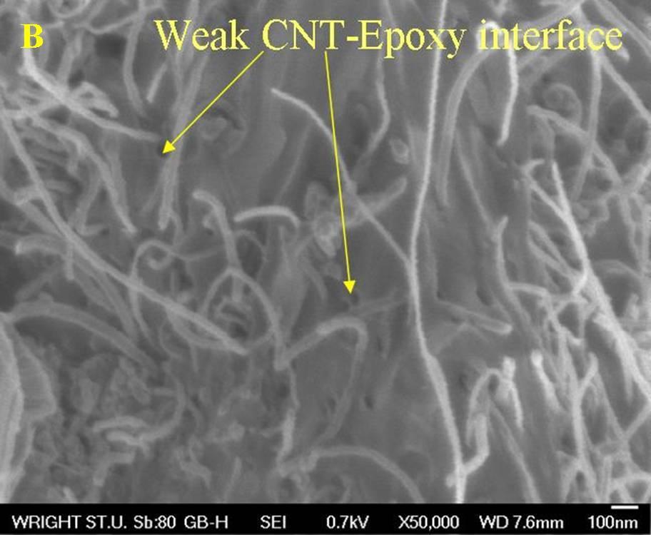
84 5.8 Role of CNT on Failure Mechanism There are three interfaces were formed in making CNT composite: carbon-oxide interface, oxide-cnt interface, and CNT-epoxy interface. Microscopic failure can initiate within carbon foam or at the any of the mentioned three interfaces. It was already discussed in the earlier section that the crack initiated in the carbon foam ligament during the compression test due to the strong interfacial bonding. In addition, higher magnification (above 20000x) electron micrographs also revealed additional information on CNT role as an interfacial reinforcement material. Since interfacial failure mechanism may changes from location to location due to complex structure of the carbon foam, electron micrographs were taken from various locations. From the electron microscopic images taken from the various locations of the failed samples, it was understood that CNT were forming a bridge across the graphite-epoxy interface and preventing any delamination that may occurred (Fig 27-A). However, with the excess stretching of interface graphite flakes were pulled away from core and ended up sticking to the epoxy (Fig 27-B). Majority of the nanotubes were remained strongly attached to the graphite even after failure (Fig 27-B). This was only possible by strong bonding between carbonoxide layer, oxide-cnt, and CNT-epoxy. However, CNT does not form any chemical bonds with the epoxy as they are so inert. If it is not chemical bonding, only CNT kinks can foam mechanical interlock with polymer chains. CNT with curves contribute greatly to the bridging the carbon foam and epoxy. 73


85 Figure 27: Interfacial failure mechanism 74
86 There are few areas where broken nanotubes are dangling from graphite core (Fig 28-A). Though there was no clear evidence showing the ends of the broken CNT due to the charging effects caused by the non-conductive epoxy, nanotubes dangling at the delaminated interface were shorter than average length (approx 20µm) of CVD grown nanotubes. It was also showed that the CNT with no significant kinks or defects were forced out of the epoxy due to their extremely smooth surfaces (Fig 28-B). This mechanism was seen from the nano-sized holes presented on the epoxy surface. Howver, this claim had lacked solid proof. Considering the nature of CNT and epoxy CNT pull out is very much a possibility. In summary, CNT bridging, breaking, and CNT pullout all contributed to the delayed fracture. It was clear from the analysis that, there were more elements (graphite ligaments, CNT slippage from epoxy, CNT braking) got involved in the failure process. Bridging helped the delayed fracture whereas CNT breaking and pullout helped the composite to absorb more energy during its failure. Though it was concluded that, CNT composite performance was due to the strong interface, there was no quantitative analysis that can be done because of the complex morphology of the carbon foam. To analyze in detail interfacial strength, study was carried out on CNT coated flat graphite coupled with epoxy. 75

87 Figure 28: Interfacial failure mechanism 76
88 6. Interface Characterization 6.1 Interface Fabrication The structure of the carbon foam is too complex and any quantitative analysis on the carbon-matrix interface makes the further analysis difficult. Geometry issues such as radius of curvature can be eliminated by producing graphite-epoxy flat interfaces using HOPG graphite. HOPG graphite surface chemistry was similar to carbon foams used in the earlier study. Details of making flat interfaces are followed: mm thick graphite samples were grafted with CNT similar to the way carbon foam was grafted. - Two of the CNT grafted graphite samples were attached together with epoxy (same epoxy used for composite making) to make CNT seam. - CNT seam was cured in the open air for 10days. - It must be noted that length of the sample (2 3.15mm+ thickness of epoxy) was restricted to 6.32 due to 3.15mm thickness HOPG sheets. - Even though, ideally one would like to do tension test on fabricated seams, the seam length was too small to hold in the tension fixtures, hence the three point bending test was selected. - Samples were cut into 6.32mm 2.5mm 2.5mm for three point bending test to enable the seam to failed by tension (Note: Anything smaller than 2.5 mm width 77
89 and thickness was effected by machine sensitivity and also in addition, smaller samples were quite difficult to make). - Similar dimension control seam fabricated by attaching two uncoated graphite sheets with an epoxy was made. - Monolithic graphite uniform graphite with no epoxy attachment was also made. 6.2 Experimental Setup Small beams of 6.32mm 2.5mm 2.5mm size were prepared for the three point bending test. Instron 4505 universal testing machine with 1kN load cell was used (Fig 29). Seams were tested at a rate of 0.5mm/min. Schematic representation of bending test has been showed in the below figures (Fig 30). The three point bending test was designed to break the seam at carbon epoxy interface and measure the load required. The flexural load and extension were recorded from the machine transducer and cross head displacement respectively. The maximum loads and corresponding deformations are recorded and maximum flexural strength and corresponding strains were calculated from Maximum flexural stress 3Pmax l... Eq (13) max 2 2bt l Flexural strain.... Eq (14) L P max = the maximum force recorded by the testing machine δl = distance moved by the cross head during the testing l = Span length = 4.52 (6.32-width of the supports) 78

90 Figure 29: Three point bending test set up Figure 30: Schematic representation of testing method 79
91 In equation 13, b and t are width (2.5mm) and thickness (2.5mm) respectively. Using equations 13 and 14, flexural strength was taken on Y-axis and flexural strain was taken on X-axis. 6.3 Results The resulting flexural load-extension plots (RAW data) are shown below for all tested samples (Fig 31). Since the sample dimensions were too small compared to traditional beam dimensions (length to thickness 16:1), strains recorded were too small to make any observations hence were neglected for the final analysis. Maximum flexural strength of the seam was calculated from equation 13. It was observed that the recorded maximum strength varies from sample to sample hence multiple samples were tested. The maximum strength of control seam varies in between 11MPa to 15MPa and averaged to 13MPa over six samples. For the CNT seam maximum strength varies from 43MPa to 47MPa and averaged to 45MPa over eight samples which was almost over 2.5 times the average strength of the control seam. Flexural strength of the monolithic graphite was 54MPa, which was close to the strength of CNT seam. Therefore, introduction of the epoxy joint affected the original strength of graphite as expected. Incase of control seam, graphite lost almost 75% of its original flexural strength whereas, in case of CNT seam it was only 20% (or it retained almost 80% of its strength). Strength of the seams tested is also shown in figure 32. All the failure load and strength results are tabulated in the table 9. 80
92 Figure 31: RAW data of three-point-bending test 81
93 Figure 32: Stress-strain graphs for base interface and CNT reinforced interface Type No of Fracture load (N) Flexural strength (MPa) samples Control seam 6 31±6 13±2 CNT seam 8 107±8 45±2 Monolithic graphite (HOPG) 8 129±8 54±2 Table 9: Strength of control seam, CNT seam, and monolithic graphite 82
94 6.4 SEM Analysis From the SEM images (Fig 33) it was clear that CNT reinforcement at the interface had changed the interface failure mechanism. The reasons cited were same as the ones stated earlier section 5.8. Carbon nanotubes were well attached to the graphite through chemical bonding, and these bonds were stronger than van-der-wall forces between graphite flakes. Though the high aspect ratio of CNT was vulnerable to fiber pull out from epoxy, nanotube entanglement with epoxy polymer chains during curing of epoxy provided a mechanical interlock needed for strengthening mechanism. Formation of high surface contact area increases interfacial shear strength between CNT and epoxy significantly. Kinks and irregularity of nanotubes were other contributing factors for mechanical interlock. There were also signs of fiber pull out (Fig 34) from the epoxy which was helped to absorb some energy during the mechanical testing. Considering the nanotube growth density, effect of fiber pull out on the strengthening mechanism was minimal. In summary, CNT Seam had failed by graphite-graphite failure whereas control seam had failed by graphite-epoxy delamination. To conclude, irrespective of the surface geometry, CNT reinforcement increases the interfacial bond strength significantly. This type of failure mechanism opened up number of future applications. 83

 and")

95 Figure 33: Microstructure failure mechanism of control (left) and CNT seam (right) Figure 34: CNT-Epoxy interface failure 84
Silver Diffusion Bonding and Layer Transfer of Lithium Niobate to Silicon
 Chapter 5 Silver Diffusion Bonding and Layer Transfer of Lithium Niobate to Silicon 5.1 Introduction In this chapter, we discuss a method of metallic bonding between two deposited silver layers. A diffusion
Composite Materials. Metal matrix composites
 Composite Materials Metal matrix composites Introduction The properties that make MMCs attractive are high strength and stiffness, good wear resistance, high service temperature, tailorable coefficient
The effects of Fe/Al 2 O 3 preparation technique as a catalyst on synthesized CNTs in CVD method.
 Science Journal of Physics Science Journal Publication Science Journal of Physics Web: http://www.sjpublication.com/sjp.html The effects of Fe/Al 2 O 3 preparation technique as a catalyst on synthesized
Reticulated foams expand the boundaries of cellular solids
 Reticulated foams expand the boundaries of cellular solids by Paul Everitt and James Taylor, Technical Development Specialists, Goodfellow Corporation Paul.Everitt@goodfellow.com James.Taylor@goodfellow.com
CHAPTER 4: The wetting behaviour and reaction of the diamond-si system
 CHAPTER 4: The wetting behaviour and reaction of the diamond-si system In this chapter, the wetting behaviour of diamond by silicon will be presented, followed by the study of the interaction between diamond
CHAPTER 7 MICRO STRUCTURAL PROPERTIES OF CONCRETE WITH MANUFACTURED SAND
 99 CHAPTER 7 MICRO STRUCTURAL PROPERTIES OF CONCRETE WITH MANUFACTURED SAND 7.1 GENERAL Characterizing the mineralogy of the samples can be done in several ways. The SEM identifies the morphology of the
THE EFFECT OF SOL-GEL TECHNIQUE ON THE ALUMINIUM SiCp COMPOSITE
 Jurnal Mekanikal June 2005, No. 19, 11 21 THE EFFECT OF SOL-GEL TECHNIQUE ON THE ALUMINIUM SiCp COMPOSITE Jamaliah Idris [1] and N.J. Nee [2] [1] Assoc. Prof. [2] Undergraduate student Faculty of Mechanical
Influence of Spraying Conditions on Properties of Zr-Based Metallic Glass Coating by Gas Tunnel Type Plasma Spraying
 Influence of Spraying Conditions on Properties of Zr-Based Metallic Glass by Gas Tunnel Type Plasma Spraying KOBAYASHI Akira *, KURODA Toshio *, KIMURA Hisamichi ** and INOUE Akihisa ** Abstract Metallic
Structure and Chemical Analysis of Carbon Nanotubes Grown on Diamond Substrate Using Three Different Techniques MRS: November 30, 2010
 Structure and Chemical Analysis of Carbon Nanotubes Grown on Diamond Substrate Using Three Different Techniques MRS: November 30, 2010 Betty T. Quinton Wright State University, PhD. Student Material Science
Effect of Hydrocarbon Solutions on Polymer Concrete
 Dr. Sanaa Abdul Hadi Applied Sciences Department, University of Technology/Baghdad. Mustafa Hassan Omar Applied Sciences Department, University of Technology/Baghdad. Email:entaomritofi8@yahoo.com Received
Surface composites: A new class of engineered materials
 Journal of MATERIALS RESEARCH Welcome Comments Help Surface composites: A new class of engineered materials Rajiv Singh and James Fitz-Gerald Department of Materials Science and Engineering, University
Introduction to Composites
 Section 1 Introduction to Composites By definition, composite materials are formed from two or more materials that have quite different properties. The resultant material has a heterogeneous microstructure
Summary. Carbon in solid form exhibit diverse structure and physical properties. It is this diversity
 Summary Carbon in solid form exhibit diverse structure and physical properties. It is this diversity coupled with the ability to prepare carbon products in complete random to perfectly aligned torm that
Development of New Generation Of Coatings with Strength-Ductility Relationship, Wear, Corrosion and Hydrogen Embrittlement Resistance Beyond the
 Development of New Generation Of Coatings with Strength-Ductility Relationship, Wear, Corrosion and Hydrogen Embrittlement Resistance Beyond the Current Materials Accomplishments till date As the structural
Observation in the GB (Gentle Beam) Capabilities
 Capabilities") A field-emission cathode in the electron gun of a scanning electron microscope provides narrower probing beams at low as well as high electron energy, resulting in both improved spatial resolution and
A field-emission cathode in the electron gun of a scanning electron microscope provides narrower probing beams at low as well as high electron energy, resulting in both improved spatial resolution and
Study and Analyze of Wear Behavior Carbon Nano Tube-Epoxy Resin Composite Material
 Study and Analyze of Wear Behavior Carbon Nano Tube-Epoxy Resin Composite Material R. Mohammad Giyahudeen 1, J. Mohammad Gazzali 2 1 Assistant Professor, Mechanical Department, Maha Barathi Engineering
CONCLUSIONS AND SCOPE FOR FUTURE WORK
 CHAPTER 9 CONCLUSIONS AND SCOPE FOR FUTURE WORK From the present study conducted on the effects of cryogenic treatment and its mechanism on AISI M2 HSS and tungsten carbide cutting tools, the following
Supporting Information
 Supporting Information Large-Area, Transfer-Free, Oxide-Assisted Synthesis of Hexagonal Boron Nitride Films and Their Heterostructures with MoS2 and WS2 Sanjay Behura, Phong Nguyen, Songwei Che, Rousan
PROCESSING AND CHARACTERIZATION OF NANOSTRUCTURED CARBON/CARBON COMPOSITES
 16 TH INTERNATIONAL CONFERENCE ON COMPOSITE MATERIALS PROCESSING AND CHARACTERIZATION OF NANOSTRUCTURED CARBON/CARBON COMPOSITES Francis Samalot*, Uday K, Vaidya** [uvaidya@uab.edu]: *The University of
Composite Materials. In depth look
 Composite Materials In depth look Classification of Composites Metals Materials Polymers Ceramics Composites Metal Matrix Composites Polymer Matrix Composites Ceramic Matrix Composites Classification of
General Introduction to Microstructure Technology p. 1 What is Microstructure Technology? p. 1 From Microstructure Technology to Microsystems
 General Introduction to Microstructure Technology p. 1 What is Microstructure Technology? p. 1 From Microstructure Technology to Microsystems Technology p. 9 The Parallels to Microelectronics p. 15 The
Fabrication Process. Crystal Growth Doping Deposition Patterning Lithography Oxidation Ion Implementation CONCORDIA VLSI DESIGN LAB
 Fabrication Process Crystal Growth Doping Deposition Patterning Lithography Oxidation Ion Implementation 1 Fabrication- CMOS Process Starting Material Preparation 1. Produce Metallurgical Grade Silicon
Analysis and design of composite structures
 Analysis and design of composite structures Class notes 1 1. Introduction 2 Definition: composite means that different materials are combined to form a third material whose properties are superior to those
Structural Composite Materials
 Structural Composite Materials F.C. Campbell The Materials Information Society ASM International Materials Park, Ohio 44073-0002 www.asminternational.org Contents Preface About the Author xi xv Chapter
COMPATIBILITY OF THE ALTERNATIVE SEED LAYER (ASL) PROCESS WITH MONO- Si AND POLY-Si SUBSTRATES PATTERNED BY LASER OR WET ETCHING
 PROCESS WITH MONO- Si AND POLY-Si SUBSTRATES PATTERNED BY LASER OR WET ETCHING") COMPATIBILITY OF THE ALTERNATIVE SEED LAYER (ASL) PROCESS WITH MONO- Si AND POLY-Si SUBSTRATES PATTERNED BY LASER OR WET ETCHING Lynne Michaelson 1, Anh Viet Nguyen 2, Krystal Munoz 1, Jonathan C. Wang
COMPATIBILITY OF THE ALTERNATIVE SEED LAYER (ASL) PROCESS WITH MONO- Si AND POLY-Si SUBSTRATES PATTERNED BY LASER OR WET ETCHING Lynne Michaelson 1, Anh Viet Nguyen 2, Krystal Munoz 1, Jonathan C. Wang
Supplimentary Information. Large-Scale Synthesis and Functionalization of Hexagonal Boron Nitride. Nanosheets
 Electronic Supplementary Material (ESI) for Nanoscale. This journal is The Royal Society of Chemistry 2014 Supplimentary Information Large-Scale Synthesis and Functionalization of Hexagonal Boron Nitride
DIRECT LASER SINTERING OF BOROSILICATE GLASS
 DIRECT LASER SINTERING OF BOROSILICATE GLASS F. Klocke, A. McClung and C. Ader Fraunhofer Institute for Production Technology IPT, Aachen, Germany Reviewed, accepted August 4, 2004 Abstract Despite the
Enhancement of connectivity and flux pinning in MgB2 superconducting bulks and wires
 University of Wollongong Research Online University of Wollongong Thesis Collection 1954-2016 University of Wollongong Thesis Collections 2009 Enhancement of connectivity and flux pinning in MgB2 superconducting
SIZE EFFECTS OF SIC PARTICLES ON MECHNICAL PROPERTIES OF CAST CARBON NANOFIBERS REINFORCED AZ91 MAGNESIUM COMPOSITES
 THE 19 TH INTERNATIONAL CONFERENCE ON COMPOSITE MATERIALS SIZE EFFECTS OF SIC PARTICLES ON MECHNICAL PROPERTIES OF CAST CARBON NANOFIBERS REINFORCED AZ91 MAGNESIUM COMPOSITES S.-K. Lee 1, S.-B. Lee 1*,
Advanced Materials for Thermal Management of Electronic Packaging
 Xingcun Colin Tong Advanced Materials for Thermal Management of Electronic Packaging Sprin ger Contents 1 Thermal Management Fundamentals and Design Guides in Electronic Packaging 1 Rationale of Thermal
Comparison of Experimental and Theoretical CTE of Al/h-BN Metal Matrix Composites
 International Journal of Material Sciences and Technology. ISSN 2249-3077 Volume 6, Number 1 (2016), pp. 13-20 Research India Publications http://www.ripublication.com Comparison of Experimental and Theoretical
Chapter 7. Evaluation of Electrode Performance by. Electrochemical Impedance
 Chapter 7 Evaluation of Electrode Performance by Electrochemical Impedance Spectroscopy (EIS) 7.1 Introduction A significant fraction of internal resistance of a cell comes from the interfacial polarization
Journal of Chemical and Pharmaceutical Research, 2017, 9(1): Research Article
: Research Article") Available online www.jocpr.com Journal of Chemical and Pharmaceutical Research, 2017, 9(1):163-167 Research Article ISSN : 0975-7384 CODEN(USA) : JCPRC5 Synthesis and Characterization of Carbon Nano Spheres
Available online www.jocpr.com Journal of Chemical and Pharmaceutical Research, 2017, 9(1):163-167 Research Article ISSN : 0975-7384 CODEN(USA) : JCPRC5 Synthesis and Characterization of Carbon Nano Spheres
Growth of large single-crystalline two-dimensional boron. nitride hexagons on electropolished copper
 Supporting Information Growth of large single-crystalline two-dimensional boron nitride hexagons on electropolished copper Roland Yingjie Tay,, Mark H. Griep, Govind Mallick,, Siu Hon Tsang, Ram Sevak
COMPOSITES. Gayathri & Yamuna
 COMPOSITES Definition A composite is a combination of two or more simple materials to get another material with better properties Examples Wood (a natural composite - comprising cellulose fibers in a lignin
COMPOSITE MATERIALS. Asst. Prof. Dr. Ayşe KALEMTAŞ
 COMPOSITE MATERIALS Office Hours: Tuesday, 16:30-17:30 akalemtas@mu.edu.tr, akalemtas@gmail.com Phone: +90 252 211 19 17 Metallurgical and Materials Engineering Department ISSUES TO ADDRESS Ceramic Materials
ENCHANCEMENT OF MECHANICAL PROPERTIES OF CAST NANO CABONS REINFORCED A356 ALUMINIUM MATRIX COMPOSITES
 THE 19 TH INTERNATIONAL CONFERENCE ON COMPOSITE MATERIALS ENCHANCEMENT OF MECHANICAL PROPERTIES OF CAST NANO CABONS REINFORCED A356 ALUMINIUM MATRIX COMPOSITES S.-B. Lee 1*, J.-W. Yi 1, B.M. Jung 1, and
The Physical Structure (NMOS)
") The Physical Structure (NMOS) Al SiO2 Field Oxide Gate oxide S n+ Polysilicon Gate Al SiO2 SiO2 D n+ L channel P Substrate Field Oxide contact Metal (S) n+ (G) L W n+ (D) Poly 1 3D Perspective 2 3 Fabrication
The Physical Structure (NMOS) Al SiO2 Field Oxide Gate oxide S n+ Polysilicon Gate Al SiO2 SiO2 D n+ L channel P Substrate Field Oxide contact Metal (S) n+ (G) L W n+ (D) Poly 1 3D Perspective 2 3 Fabrication
Supporting Information. Low temperature synthesis of silicon carbide nanomaterials using
 Supporting Information Low temperature synthesis of silicon carbide nanomaterials using solid-state method Mita Dasog, Larissa F. Smith, Tapas K. Purkait and Jonathan G. C. Veinot * Department of Chemistry,
Specimen Preparation Technique for a Microstructure Analysis Using the Focused Ion Beam Process
 Specimen Preparation Technique for a Microstructure Analysis Using the Focused Ion Beam Process by Kozue Yabusaki * and Hirokazu Sasaki * In recent years the FIB technique has been widely used for specimen
DEGRADATION THE REFRACTORIES OF ROTARY FURNACE LININGS IN THE PRODUCTION OF ZINC OXIDE
 DEGRADATION THE REFRACTORIES OF ROTARY FURNACE LININGS IN THE PRODUCTION OF ZINC OXIDE Natália LUPTÁKOVÁ a, Františka PEŠLOVÁ a, Evgeniy ANISOMOV b, Adriana PAVÚČKOVÁ a, Michaela FERODOVÁ a a University
Characterization of Carbon Nanotube Reinforced Aluminium Nanocomposite using Field Emission Scanning Electron Microscope
 International Journal of Engineering Materials and Manufacture (2018) 3(1) 63-67 https://doi.org/10.26776/ijemm.03.01.2018.08 Characterization of Carbon Nanotube Reinforced Aluminium Nanocomposite using
Enhancement Surface Mechanical Properties of 2024 Al-Alloys Using Pulsed Nd:YAG Laser Cladding
 Enhancement Surface Mechanical Properties of 2024 Al-Alloys Using Pulsed Nd:YAG Laser Cladding 1 1 2 Raid M.HadiP P, Mahmoad Sh. MahmoadP P and Ali H.AbdalhadiP Institute of laser for postgraduate studies,
Declaration. Aron Tamisa Shonhiwa
 Declaration I declare that this thesis is my own work. It is being submitted for the degree of Doctor of Philosophy in the University of the Witwatersrand. It has not been submitted before for any other
Laser Processing on Graphite
 Laser Processing on Graphite MSE 503 Seminar - Fall 2009 08-27-2009 CLA Conference Room, UT Space Institute, Tullahoma, TN - 37388, USA Deepak Rajput Graduate Research Assistant Center for Laser Applications
CHAPTER 4. SYNTHESIS OF ALUMINIUM SELENIDE (Al 2 Se 3 ) NANO PARTICLES, DEPOSITION AND CHARACTERIZATION
 NANO PARTICLES, DEPOSITION AND CHARACTERIZATION") 40 CHAPTER 4 SYNTHESIS OF ALUMINIUM SELENIDE (Al 2 Se 3 ) NANO PARTICLES, DEPOSITION AND CHARACTERIZATION 4.1 INTRODUCTION Aluminium selenide is the chemical compound Al 2 Se 3 and has been used as a precursor
40 CHAPTER 4 SYNTHESIS OF ALUMINIUM SELENIDE (Al 2 Se 3 ) NANO PARTICLES, DEPOSITION AND CHARACTERIZATION 4.1 INTRODUCTION Aluminium selenide is the chemical compound Al 2 Se 3 and has been used as a precursor
Mechanical Properties and Interfacial Characterization of Nextel 312 Fiber/BN/Blackglas Composites
 Mechanical Properties and Interfacial Characterization of Nextel 312 Fiber/BN/Blackglas Composites Richard L. Schalek *, John Helmuth **, and Lawrence T. Drzal #* * Composite Materials and Structures Center,
Application Note #124 VITA: Quantitative Nanoscale Characterization and Unambiguous Material Identification for Polymers
 Local thermal analysis identifies polymer AFM image of polymer blend Application Note #124 VITA: Quantitative Nanoscale Characterization and Unambiguous Material Identification for Polymers VITA module
Correlating Thermal Barrier Coating Microstructure Between Engine Run Combustion Hardware and Furnace Cycle Testing
 Correlating Thermal Barrier Coating Microstructure Between Engine Run Combustion Hardware and Furnace Cycle Testing Kara Phillips Bridges Solar Turbines Incorporated Materials and Processes Engineering
StressX: XRD Solution to Residual Stress Determination in Industrial Application Field
 StressX: XRD Solution to Residual Stress Determination in Industrial Application Field Alessandro Torboli X-Ray Marketing Manager GNR Analytical Instruments Group 25-26 April 2017 GIZEF - Freiberg G.N.R.
Final Year Project Proposal 1
 Final Year Project Proposal 1 Mechanical testing for high temperature polymers Mr Eric Phua Jian Rong (JRPhua@ntu.edu.sg) In offshore subsea drilling, different types of microelectronics devices and sensors
THERMALLY CONDUCTIVE, TOUGH SILICON CARBIDE COMPOSITE ATTEMPTING TO MIMIC NATURE WITH HIGH STRENGTH UP TO 1600 o C IN AIR ABSTRACT
 THERMALLY CONDUCTIVE, TOUGH SILICON CARBIDE COMPOSITE ATTEMPTING TO MIMIC NATURE WITH HIGH STRENGTH UP TO 1600 o C IN AIR Toshihiro Ishikawa Inorganic Specialty Products Research Laboratory, Ube Industries,
Heteroepitaxy of Monolayer MoS 2 and WS 2
 Supporting Information Seed Crystal Homogeneity Controls Lateral and Vertical Heteroepitaxy of Monolayer MoS 2 and WS 2 Youngdong Yoo, Zachary P. Degregorio, James E. Johns* Department of Chemistry, University
CONTENTS. Preface to the 3rd Edition Acknowledgments
 CONTENTS Preface to the 3rd Edition Acknowledgments vii ix CHAPTER 1 INTRODUCTION 1 1.1 Definition of materials degradation 1 1.2 Definition and significance of surface engineering 4 1.3 Classification
Introduction to Composite Materials
 Structural Composite Materials Copyright 2010, ASM International F.C. Campbell All rights reserved. (#05287G) www.asminternational.org Chapter 1 Introduction to Composite Materials A composite material
SIC3 Specification. Vacuum Heating Technology. General Properties XRD
 Vacuum Heating Technology Thermic Edge Ltd are the sole manufacturers of SiC 3, short for cubic silicon carbide. The process is unique as it combines a well defined crystal size, isotropic structure and
ECE 440 Lecture 27 : Equilibrium P-N Junctions I Class Outline:
 ECE 440 Lecture 27 : Equilibrium P-N Junctions I Class Outline: Fabrication of p-n junctions Contact Potential Things you should know when you leave Key Questions What are the necessary steps to fabricate
Jānis Grabis. Plasma chemical synthesis of multicomponent nanopowders, their characteristics, and processing
 Jānis Grabis Plasma chemical synthesis of multicomponent nanopowders, their characteristics, and processing Outline Introduction nanoparticles, their preparation methods Experimental synthesis of multicomponent
Mechanical Properties of Bulk Metallic Glasses and composites
 Mechanical Properties of Bulk Metallic Glasses and composites M.L. Lee 1 *, Y. Li 1, 2, Y. Zhong 1, C.W. Carter 1, 3 1. Advanced Materials for Micro- and Nano- Systems Programmes, Singapore-MIT Alliance,
The preparation and properties of novel structural carbon foams derived from different mesophase pitches
 Engineering Conferences International ECI Digital Archives 5th International Conference on Porous Media and Their Applications in Science, Engineering and Industry Refereed Proceedings Summer 6-23-2014
DEVELOPMENT AND CHARACTERIZATION OF ALUMINA/ALUMINUM CO-CONTINUOUS COMPOSITE BY REACTIVE MELT INFILTRATION TECHNIQUE
 Journal of Quality and Technology Management Volume VIII, Issue I, June 2012, Page 71 82 DEVELOPMENT AND CHARACTERIZATION OF ALUMINA/ALUMINUM CO-CONTINUOUS COMPOSITE BY REACTIVE MELT INFILTRATION TECHNIQUE
Nanyang Technological University School of Materials Science & Engineering
 Final Year Project Proposal 1 3D Assembly of Nano/Micro Zirconia Particles for Enhanced Energy Damping Capacity Dr Du Zehui (duzehui@ntu.edu.sg) To develop the best possible method to assemble micro/nano-scale
CHAPTER 3. Experimental Results of Magnesium oxide (MgO) Thin Films
 Thin Films") CHAPTER 3 Experimental Results of Magnesium oxide (MgO) Thin Films Chapter: III ---------------------------------------------------------------- Experimental Results of Magnesium oxide (MgO) Thin Films
CHAPTER 3 Experimental Results of Magnesium oxide (MgO) Thin Films Chapter: III ---------------------------------------------------------------- Experimental Results of Magnesium oxide (MgO) Thin Films
Research in Experimental Solid Mechanics. Krishna Jonnalagadda Mechanical Engineering Indian Institute of Technology Bombay
 Research in Experimental Solid Mechanics Krishna Jonnalagadda Mechanical Engineering Indian Institute of Technology Bombay TEQIP Workshop - Experimental Solid Mechanics Indian Institute of Technology Bombay
MICROSTRUCTURE BASED FINITE ELEMENT ANALYSIS FOR DEFORMATION BEHAVIOUR OF MAGNESIUM BASED COMPOSITES
 MICROSTRUCTURE BASED FINITE ELEMENT ANALYSIS FOR DEFORMATION BEHAVIOUR OF MAGNESIUM BASED COMPOSITES Prasanth Kumar B, T V V L N Rao and Masri Baharom Department of Mechanical Engineering, Universiti Teknologi
PREPARATION AND CHARACTERIZATION OF EPOXY COMPOSITE REINFORCED WITH WALNUT SHELL POWDER
 PREPARATION AND CHARACTERIZATION OF EPOXY COMPOSITE REINFORCED WITH WALNUT SHELL POWDER C.B.Talikoti 1, T.T.Hawal 2, P.P.Kakkamari 3, Dr. M.S.Patil 4 1.M.Tech scholar, Dept. of Mechanical Engineering,
Microstructural Characterization of Materials
 Microstructural Characterization of Materials 2nd Edition DAVID BRANDON AND WAYNE D. KAPLAN Technion, Israel Institute of Technology, Israel John Wiley & Sons, Ltd Contents Preface to the Second Edition
By *T.Khalil, **J. Bossert,***A.H.Ashor and *F. Abou EL-Nour
 WM 11 EG0100132 Seventh Conference of Nuclear Sciences & Applications 6-10 February 2000. Cairo, Egypt Preparation, Characterization and application of Alumina powder Produced by advanced Preparation Techniques
Growth and Doping of SiC-Thin Films on Low-Stress, Amorphous Si 3 N 4 /Si Substrates for Robust Microelectromechanical Systems Applications
 Journal of ELECTRONIC MATERIALS, Vol. 31, No. 5, 2002 Special Issue Paper Growth and Doping of SiC-Thin Films on Low-Stress, Amorphous Si 3 N 4 /Si Substrates for Robust Microelectromechanical Systems
Summary Chapter Chapter Chapter
 Ceria (CeO 2 ) has been extensively employed as an important component of automotive three-way catalysts (TWC) for reducing the exhaust pollutants. Besides this, fuel cell processes, oxygen permeation
Influence of Angle Ply Orientation on Tensile Properties of Carbon/Glass Hybrid Composite
 Journal of Minerals and Materials Characterization and Engineering, 2013, 1, 231-235 http://dx.doi.org/10.4236/jmmce.2013.15036 Published Online September 2013 (http://www.scirp.org/journal/jmmce) Influence
Analysis of Mechanical and Metallurgical properties of Al-SiCp Composite by Squeeze-cum-Stir Casting
 International Journal of Research in Engineering and Science (IJRES) ISSN (Online): 2320-9364, ISSN (Print): 2320-9356 Volume 2 Issue 5 ǁ May. 2014 ǁ PP.45-49 Analysis of Mechanical and Metallurgical properties
Metal Matrix Composite (MMC)
") Matrix Metal Matrix Composite (MMC) The matrix is the monolithic material into which the reinforcement is embedded, and is completely continuous. This means thatt there is apath throughh the matrix ti
Matrix Metal Matrix Composite (MMC) The matrix is the monolithic material into which the reinforcement is embedded, and is completely continuous. This means thatt there is apath throughh the matrix ti
CHEMICAL DEPTH PROFILING OF TOOL MATERIALS USING GLOW DISCHARGE OPTICAL EMISSION SPECTROSCOPY (GD-OES)
") CHEMICAL DEPTH PROFILING OF TOOL MATERIALS USING GLOW DISCHARGE OPTICAL EMISSION SPECTROSCOPY (GD-OES) T. Björk Swedish Institute for Metals Researc Drottning Kristinas väg 48 114 28 Stockholm Sweden Abstract
CHEMICAL DEPTH PROFILING OF TOOL MATERIALS USING GLOW DISCHARGE OPTICAL EMISSION SPECTROSCOPY (GD-OES) T. Björk Swedish Institute for Metals Researc Drottning Kristinas väg 48 114 28 Stockholm Sweden Abstract
A Study of Additive Diffusion in Ferrous Powder Metal Compacts Using Scanning Electron Microscopy and Energy Dispersive X-Ray Spectroscopy
 A Study of Additive Diffusion in Ferrous Powder Metal Compacts Using Scanning Electron Microscopy and Energy Dispersive X-Ray Spectroscopy Brian A. Sparber, Steven R. Spurgeon, and Mitra L. Taheri Department
Effects of Hydrogen Flow Rate on Carbon Nanotube Growth
 Effects of Hydrogen Flow Rate on Carbon Nanotube Growth Carolyn Reynolds*, Binh Duong**, and Supapan Seraphin** *Dept. Optical Engineering, Norfolk State University, Norfolk, VA 23504; **Dept. Materials
Microstructure and Vacuum Leak Characteristics of SiC coating Layer by Three Different Deposition Methods
 Microstructure and Vacuum Leak Characteristics of SiC coating Layer by Three Different Deposition Methods Y. Kim Professor, Department of Materials Science and Engineering, College of Engineering, Kyonggi
CHAPTER TWO-BODY ABRASIVE WEAR BEHAVIOR
 123 CHAPTER 6 ABRASIVE WEAR BEHAVIOR OF UNFILLED AND SILANE-TREATED SILICON CARBIDE (SiC) PARTICLES FILLED CARBON FABRIC REINFORCED EPOXY MATRIX HYBRID COMPOSITES 6.1 INTRODUCTION With the initiation of
Mobile repair of hard coated rolls and machine components. ICE Europe Technical Program, Dr. A. Barth,
 Mobile repair of hard coated rolls and machine components ICE Europe Technical Program, Dr. A. Barth, 22.03.2017 Technological Competence and Scope Full Service Surface Technology Surface Treatments Mechanical
Arch. Metall. Mater. 62 (2017), 2B,
, 2B,") Arch. Metall. Mater. 6 (7), B, 9- DOI:.55/amm-7- B.-H. KANG*, M.-H. PARK**, K.-A. LEE*** # EFFECT OF STRUT THICKNESS ON ROOM AND HIGH TEMPERATURE COMPRESSIVE PROPEIES OF BLOCK-TYPE Ni-Cr-Al POWDER POROUS
Arch. Metall. Mater. 6 (7), B, 9- DOI:.55/amm-7- B.-H. KANG*, M.-H. PARK**, K.-A. LEE*** # EFFECT OF STRUT THICKNESS ON ROOM AND HIGH TEMPERATURE COMPRESSIVE PROPEIES OF BLOCK-TYPE Ni-Cr-Al POWDER POROUS
β Silicon Carbide Coated MWCNTs Reinforced Polyetherimide Nanocomposites
 β Silicon Carbide Coated MWCNTs Reinforced Polyetherimide Nanocomposites β Silicon Carbide Coated MWCNTs Reinforced Polyetherimide Nanocomposites Nitin Nagar, K.N. Pandey *, Pratibha Singh, Vishal Verma,
MSE 351 Engineering Ceramics I
 Kwame Nkrumah University of Science & Technology, Kumasi, Ghana MSE 351 Engineering Ceramics I Ing. Anthony Andrews (PhD) Department of Materials Engineering Faculty of Mechanical and Chemical Engineering
MESOPHASE AR PITCH DERIVED CARBON FOAM: EFFECT OF TEMPERATURE, PRESSURE AND PRESSURE RELEASE TIME
 MESOPHASE AR PITCH DERIVED CARBON FOAM: EFFECT OF TEMPERATURE, PRESSURE AND PRESSURE RELEASE TIME Gencay, N. 1, Eksilioglu, A. 1, Gul, A. 1, Karadag, F. 1, Ekinci. E. 1, Yardim, M.F. 1 1 Istanbul Technical
ANALYTICAL STUDY OF FACTORS AFFECTING AND APPLICATION OF FINITE ELEMENT ANALYSIS FOR HEAT TRANSFER THROUGH FIBER REINFORCED COMPOSITE MATERIALS
 Review Article ISSN 2278 0149 www.ijmerr.com Vol. 3, No. 3, July, 2014 2014 IJMERR. All Rights Reserved ANALYTICAL STUDY OF FACTORS AFFECTING AND APPLICATION OF FINITE ELEMENT ANALYSIS FOR HEAT TRANSFER
Visit
 Practical Applications for Nano- Electronics by Vimal Gopee E-mail: Vimal.gopee@npl.co.uk 10/10/12 Your Delegate Webinar Control Panel Open and close your panel Full screen view Raise hand for Q&A at the
LOW TEMPERATURE PHOTONIC SINTERING FOR PRINTED ELECTRONICS. Dr. Saad Ahmed XENON Corporation November 19, 2015
 LOW TEMPERATURE PHOTONIC SINTERING FOR PRINTED ELECTRONICS Dr. Saad Ahmed XENON Corporation November 19, 2015 Topics Introduction to Pulsed Light Photonic sintering for Printed Electronics R&D Tools for
Injection Moulding and Heat Treatment of Ni-Cr-Si-B Alloy Powder
 Injection Moulding and Heat Treatment of Ni-Cr-Si-B Alloy Powder M. Y. Anwar 1, M. Ajmal 1, M. T. Z. Butt 2 and M. Zubair 1 1. Department of Met. & Materials Engineering, UET Lahore. 2. Faculty of Engineering
4-in-1 Nano Machine & Technology
 4-in-1 Nano Machine & Technology Machine combines 1) CVD, 2) PVD, 3) ion saturation and 4) ion-treatment processes in one (1) production cycle in one machine that produces functional coatings used to harden
Low frequency magnetic shielding: Nanocrystalline coating vs. ferromagnetic foils.
 Low frequency magnetic shielding: Nanocrystalline coating vs. ferromagnetic foils. Nanovate -EM is an innovative direct coating technique proven to be a value-add alternative to conventional foils. Magnetic
Thermal Durability and Abradability of Plasma Sprayed Al-Si-Polyimide Seal Coatings p. 85
 Trends in Automotive Applications of Thermal Spray Technology in Japan p. 1 Production Plasma in the Automotive Industry: A European Viewpoint p. 7 The Effect of Microstructure on the Wear Behavior of
Supplementary Information
 Supplementary Information Atmospheric microplasma-functionalized 3D microfluidic strips within dense carbon nanotube arrays confine Au nanodots for SERS sensing Samuel Yick, Zhao Jun Han and Kostya (Ken)
Design and fabrication of functionally graded components by selective laser melting. C. N. Sun*#, S. Y. Choy*+, K. F. Leong*+, J.
 Solid Freeform Fabrication 216: Proceedings of the 26th 27th Annual International Solid Freeform Fabrication Symposium An Additive Manufacturing Conference Design and fabrication of functionally graded
Bonding strength of Al/Mg/Al alloy tri-metallic laminates fabricated
 Bull. Mater. Sci., Vol. 34, No. 4, July 2011, pp. 805 810. Indian Academy of Sciences. Bonding strength of Al/Mg/Al alloy tri-metallic laminates fabricated by hot rolling X P ZHANG, *, M J TAN, T H YANG,
Materials Synthesis Via Directed Vapor Deposition
 Chapter 6 Materials Synthesis Via Directed Vapor Deposition 6.1 Overview Experimental work was undertaken to explore the ability of Directed Vapor Deposition to synthesize a variety of films in a low vacuum
Chapter 3: Powders Production and Characterization
 Chapter 3: Powders Production and Characterization Course Objective... To introduce selective powder production processes and characterization methods. This course will help you : To understand properties
01 Introduction to the Course. Introduction to Metallurgy and Materials. Welcome to MME131: January 2018 Term
 Welcome to MME131: Introduction to Metallurgy and Materials January 2018 Term A. K. M. B. Rashid Professor, Department of MME BUET, Dhaka 01 Introduction to the Course Topics to Cover Why study materials
UV15: For Fabrication of Polymer Optical Waveguides
 CASE STUDY UV15: For Fabrication of Polymer Optical Waveguides Master Bond Inc. 154 Hobart Street, Hackensack, NJ 07601 USA Phone +1.201.343.8983 Fax +1.201.343.2132 main@masterbond.com CASE STUDY UV15:
Structure-Property Correlation [1] Structure-processing-properties-performance relation
![Structure-Property Correlation [1] Structure-processing-properties-performance relation](/thumbs/86/94718537.jpg "Structure-Property Correlation [1] Structure-processing-properties-performance relation") MME 297: Lecture 04 Structure-Property Correlation [1] Structure-processing-properties-performance relation Dr. A. K. M. Bazlur Rashid Professor, Department of MME BUET, Dhaka Topics to discuss today...
MME 297: Lecture 04 Structure-Property Correlation [1] Structure-processing-properties-performance relation Dr. A. K. M. Bazlur Rashid Professor, Department of MME BUET, Dhaka Topics to discuss today...
A Preliminary Report on Phygen s Chromium Nitride Coatings. John B. Woodford, Ph.D. and. Mohumad al-zoubi, Ph.D. Argonne National Laboratory
 A Preliminary Report on Phygen s Chromium Nitride Coatings by John B. Woodford, Ph.D and Mohumad al-zoubi, Ph.D Argonne National Laboratory Introduction To protect a vulnerable surface from wear or chemical
Production of Functionally Graded Foams by Solid State Process
 International Journal of Electrospun Nanofibers and Applications, Vol. 4, No. 1 (January-June, 2018) ISSN : 0973-628X Production of Functionally Graded Foams by Solid State Process Abstract: In the present