DISCONTINUITIES AND DEFECTS. Training Workbook
|
|
|
- Shauna Dorcas Harrison
- 5 years ago
- Views:
Transcription
1 DISCONTINUITIES AND DEFECTS Training Workbook EW Written by the Staff of Hobart Institute of Welding Technology Additional copies can be obtained from: Hobart Institute of Welding Technology 400 Trade Square East Troy, Ohio (937) Hobart Institute of Welding Technology, 400 Trade Square East, Troy, Ohio, U.S.A. All rights reserved. Printed in the United States of America. ISBN:
2 TABLE OF CONTENTS TOPIC PAGE Glossary of Welding Terms iv Welding Inspector Responsibilities Related to Discontinuities and Defects 1 Identification and Definition of Weld Discontinuities and Defects 5 Common Causes of Discontinuities Related to Shape, Size, and Contour 15 Common Causes of Discontinuiies Related to Internal Inconsistencies and Weld Metal Irregularities 23 Common Causes of Discontinuities Related to Weld and Base Metal Properties 32 iii


3 TOPIC 1 WELD INSPECTOR RESPONSIBILITIES RELATED TO DISCONTINUITIES AND DEFECTS OBJECTIVE To list the specific responsibilities or duties that welding inspectors assume as related to discontinuities and defects. INTRODUCTION This section includes the responsibilities of the welding inspector as they relate to the evaluation of weldments; the identification and classification of discontinuities; and the conditions that exist when evaluating discontinuities in order to decide whether they are acceptable or unacceptable. Evaluating for discontinuity DEFINITIONS The term discontinuity has many meanings, but for purposes here, we will refer to it as an interruption of the typical structure of a weld or a weldment; this means that the weld or weldment lacks uniformity in mechanical, metallurgical, or physical characteristics. A discontinuity is not necessarily a defect unless it is unable to meet minimum acceptance standards or specifications. The term defect means the unacceptability of a weld or weldment. Discontinuity, Undercut QUALITY Quality has many meanings. A quality weld will successfully sustain the service it encounters. The quality of welds must be based on codes and standards that anticipate the service of the product. For some, there are no applicable codes or specifications. For these products, the producer must maintain quality in order to compete. The success of maintaining the balance between quality requirements and cost factors is decided in the field and in the marketplace. The responsibility for producing quality products rests on engineers, designers, welding supervisors, welders, and quality control and inspection personnel. Defect 1


4 WELDING INSPECTOR RESPONSIBILITIES The responsibilities of the welding inspector are many. Perhaps the most important responsibility is the ability to read and understand all welding drawings and written specifications. Also, the welding inspector should review all documented instructions such as codes, construction details, welding procedures, material specifications, and any special procedures required for the weldment. Read engineering drawings. The inspector s duty is to assure that the proper evaluation of test results is accomplished. With the use of codes and standards as a guide, the inspector can determine the results. Documented workmanship standards, based on codes, are used as a guide for evaluating weldments. Maintaining and preparing reports for records is another of the inspector s jobs. The reports should state general characteristics of the job, the job s conformity to the code, and any difficulties that may have occurred, with a clear and descriptive statement of any defects. Maintain reports. The inspector examines yet-to-be-welded joints to confirm their conformity to the weld joint detail included in the procedure. Proper joint fit-up and edge preparation are equally important. The alignment and root opening of parts must be inspected to determine their conformance to the construction of joint detail. Proper joint fit-up.


5 A common cause for many weld failures is the use of inadequate welding procedures, the inaccurate interpretation of procedures, or not using procedures during production. The inspector must verify the procedures are correct and properly implemented. The inspector should maintain records of qualified welders and weld operators. A weld can meet all standards, but if the welder or operator is not qualified to do the work, the weld may be rejected. Verify procedures. The inspector must verify the correct purchasing of welding materials and consumables. To assist in making selections, filler metals are specified by the American Welding Society (AWS), and base materials are commonly specified by the American Society of Testing and Materials (ASTM). The inspector must identify and verify the materials received, verify the chemical composition and mechanical properties of the material, and check for imperfections and deviations that might cause problems during production. The inspector also verifies correct storage of filler materials according to specifications. Verify correct purchasing of material. Special procedures may be written for post-weld heat treatments, assembly, and final finishing. The inspector verifies the condition of equipment to be used for welding and testing, and any special equipment required for other treatments. The capability, calibration and safety of equipment should be accurately investigated to prevent possible nonconforming workmanship in weldfabricated parts. SUMMARY Investigate for proper workmanship. Many weld defects can be eliminated before they occur if the inspector knows and accepts his/her responsibilities. 3
6 TOPIC 1 REVIEW QUESTIONS 1. What is the difference between a discontinuity and a defect? 2. On what documents is weld quality often based? 3. List the responsibilities of a welding inspector. 4


7 TOPIC 2 THE IDENTIFICATION AND DEFINITION OF WELD DISCONTINUITIES AND DEFECTS OBJECTIVE To be able to identify and define the various types of discontinuities and defects. INTRODUCTION Shape, size, and contour. Structural discontinuities. Size. Excessive face reinforcement Internal consistency of welds. In order to evaluate weldments, the weld inspector should have the ability to identify weld discontinuities. Discontinuities can be grouped into three classes. The first group relates to shape, size, and contour, which are the external dimensions of a weld. The second group relates to the internal consistency of welds, and is referred to as structural discontinuities. The third group is weld and base metal properties, which relates to the match between weld metal and base metal. SHAPE, SIZE AND CONTOUR Shape, size and contour can be broken down further to welds with excessive reinforcement, incorrect size, incorrect profile, and incorrect final weldment dimensions. Excessive Weld Reinforcement Excessive face reinforcement is extra metal deposited in a weld, forming a highly convex contour on the side of the joint from which welding is done. Excessive root reinforcement is extra weld metal deposited in the root of the weld. It is more common with joint designs which have root openings. Incorrect Weld Size The size of a groove weld is measured by the shortest distance from the root of a weld to its face, less any reinforcement. It is generally equal to the base metal thickness, on full penetration welds. When the plates are of unequal thickness, the thickness of the thinner plate determines the size of the groove weld. A slight reinforcement is usually specified. Groove size 5


8 Face reinforcement Leg and size Leg and size Weld size Excessive reinforcement is not only wasteful, but decreases the working strength of the joint due to the concentration of stresses at the toes. The size of a fillet weld is designated as its shortest leg length, a measurable dimension used to deposit the weld. The leg is the distance from the root of the joint to the toe. For strength, the size of a fillet weld is the leg length of the largest isosceles right triangle that can be inscribed within the weld. The effective size for strength for flat and convex welds is equal to the leg size, but for concave welds it is less than the actual leg length. Incorrect size welds may be determined visually with gages or by comparison with approved workmanship samples. Size Leg Incorrect Weld Profile Incorrect weld profile is a weld that does not meet the requirements for size or contour. Overlap is the bulging or protruding portion of a weld that extends beyond the toe, face, or root. In both fillet and groove welds, it can reduce the size and strength, and concentrate stresses at the weld toes. Overlap of a weld Insufficient throat or underfill is a weld face or root that is depressed or extends below the adjacent base metal surfaces. Insufficient throat or underfill 6


9 Undercut Undercut is a groove melted into the base metal adjacent to the toe or root of a weld, and left unfilled. It is usually found at the side wall or face of a groove, at the edge of a weld or layer, or at the toes of the cover pass, resulting in a reduction of base metal thickness at the point of undercut. In fillet welds, it tends to reduce the size and strength of the weld, as well as promoting stress concentrations at the toes. Excessive convexity is a highly convex contour formed by excessive reinforcement. Excessive convexity Incorrect Final Weldment Dimensions Distortion and warpage are caused by the nonuniform expansion and contraction of weld and base metal during the heating and cooling process of welding. If warpage changes the required dimensions of the total weldment, the weldment may not be acceptable. Distortion Warpage INTERNAL INCONSISTENCIES OR IRREGULARITIES Internal inconsistencies are cracks, porosity, slag inclusions, tungsten inclusions, incomplete fusion, and inadequate joint penetration. Cracks Porosity Inclusions Inadequate joint penetration 7


10 Cracks are fractures that cause an opening or a split in the weld or base metal. They can be classified as hot cracks, which occur at high temperatures during solidification, or cold cracks, which occur after solidification is complete. Both types can be categorized by physical relationships, which is their location within the weld or weldment. Cracks are fractures that cause an opening or a split in the weld or base metal. A longitudinal crack runs along parallel to the axis of the weld. A transverse crack runs perpendicular to the axis of the weld. It is often located near or in poor restarts or other internal discontinuities. Longitudinal crack. Transverse crack. Crater cracks occur in the depression left at the termination of the weld bead. Crater cracks are serious when located near the end of a weld because they can lead to other cracks. They can be star-shaped or in a single direction, either longitudinal or transverse. Weld metal cracks are longitudinal in the weld and originate from the face or root. Weld metal crack


11 Toe cracks originate and grow from the toe of the weld where high amounts of stress are most common. Toe crack Root cracks are located along the root of the weld. Root crack An arc strike is a heat-affected surface, any localized remelted metal surface, or change in surface profile caused by an arc. Arc strikes are often considered as blemishes but can be serious and lead to cracking of the weld or weldment if not removed by sufficient grinding. Arc strike Heat-affected zone cracks or underbead cracks occur during the cooling cycle after solidification of the weld and normally do not extend to the surface of the weldment. They are short but can connect with others to become continuous cracks. They can occur after a part is in service because of the embrittlement of the weld and the heat-affected zone. Heat affected zone cracks Porosity is entrapped gas cavities formed during solidification of the weld. Uniformly scattered porosity is found throughout the weld. Uniformly scattered porosity 9


12 Clustered porosity is found in groups at specific points. Clustered porosity Linear porosity generally follows a line parallel to the axis of the weld. Linear porosity Piping porosity, or worm holes or blow holes, appear as a cylindrical cavity. Piping porosity Slag inclusions are nonmetallic solid material trapped within the weld metal or between the weld and base metal during solidification. Internal slag entrapment is elongated and generally parallel with the weld axis. It occurs between passes or next to the face of a groove weld. It is sometimes called wagon tracks. Tungsten or metallic inclusions are electrode particles trapped in the weld deposit. These discontinuities are associated with gas tungsten arc or plasma arc welding processes. They can be either scattered in fine particles or in one large particle when the electrode is broken off in the puddle. Tungsten inclusions


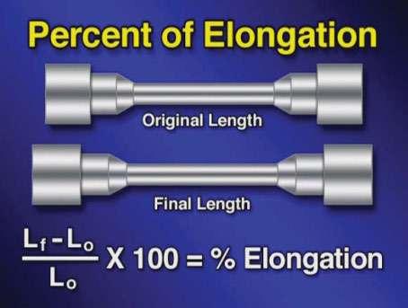
13 Incomplete fusion is the failure of the liquid weld metal to flow into and fuse the total face area of the joint. Incomplete fusion Inadequate joint penetration is penetration which is less than specified. It is located at the root of the weld. Inadequate joint penetration Seams and laps WELD AND BASE METAL MECHANICAL AND CHEMICAL PROPERTIES Sometimes specific mechanical, chemical, or physical properties are required in welds. These requirements depend upon the type of material being welded and service requirements of the weldment. Mechanical properties that must be checked against prescribed requirements include: tensile strength, yield strength, ductility, and impact strength. Tensile strength is the resistance to breaking offered by metals when subjected to pulling stress. Yield strength is the maximum load per unit area that a material can withstand without being permanently deformed. Ductility is the ability of metals to be drawn, stretched, or twisted without breaking.


14 Impact strength is the ability of a material to resist sudden or shock loading. Impact strength Chemical properties must be checked against prescribed requirements. The base and weld metal must be chemically compatible. Other chemical elements in the environment surrounding the welding process, such as nitrogen, hydrogen, and oxygen, as well as flux and shielding gases must also be considered. Any incorrect match of mechanical or chemical properties between the weld and base metal may lead to weld failure. Base metal property requirements may be defined by applicable specifications or codes. Departure from these requirements may be cause for rejection. Comparison of metals Other conditions of the base metal which may impair the ability of a material to perform as expected can include laminations, delaminations, seams, laps, and lamellar tears. Laminations are flat, elongated, sandwich discontinuities normally found near the center of structural metals. They run parallel to the manufactured surface of the plate. Metals containing laminations cannot reliably carry stress in the through-thickness direction. Lamination


15 Delaminations are laminations that have separated due to stresses. Delamination Seams and laps are longitudinal base metal discontinuities. These are most critical when located perpendicular to the principle stress. When they are perpendicular to the applied stress they can become a crack. Welding over them may result in additional cracking. Cracking is less likely to occur when the stress is located parallel to the seam or lap. Seams and laps Lamellar tears are discontinuities that occur during or after welding. They usually appear as a stair step defect caused by contraction forces during solidification. They may extend over long distances and are deeper than heat-affected zone cracks. SUMMARY Lamellar tears The weld inspector should have a working knowledge of the service requirements of the weldment, as well as the codes and standards that apply to any particular job. The inspector s goal should be to insure the closest possible accuracy to the details of the weldment specifications. 13
16 TOPIC 2 REVIEW QUESTIONS 1. What are the three groups of discontinuities? 2. Excessive reinforcement can be described as: 3. What is undercut? 4. What are two factors contributing to dimensional defects? 5. What are the types of cracks? (Give a brief explanation of each.) 6. What are the four types of porosity? 7. What are slag inclusions, and tungsten inclusions, and what is the difference between them? 8. Name and define the four mechanical properties that must be checked against prescribed requirements. 9. What is the difference between lamination and delamination? 10. What usually happens when you weld over a seam or a lap?


17 TOPIC 3 THE COMMON CAUSES OF DISCONTINUITIES RELATED TO SHAPE, SIZE AND CONTOUR OBJECTIVE To be able to identify and determine the common causes of weld discontinuities. In order for welding inspectors to perform their duties effectively, the causes of weld or weldment discontinuities must be clearly understood. Knowledge of the causes permits quality control personnel to determine where further or earlier inspection should be performed and to be sure that procedures are being properly followed. One of the jobs of a welding inspector is to inspect the weldment and assure that it meets the requirements of the design. The inspector must be familiar with the standards which spell out acceptable limits and must also be familiar with the weld procedure that pertains to the particular weldment. Excessive reinforcement refers to extra weld metal that is deposited in the joint either at the root or face, forming a highly convex contour. The most common causes of excessive reinforcement are: poor joint fit-up; incorrect welding technique; incorrect welding current settings; and improper selection of filler metals or electrodes. Excessive reinforcement adds unnecessary cost and weight to a weldment. Excessive root reinforcement Different sizes A fit-up or root opening which is too wide or a root face which is too small will contribute to excessive root reinforcements. Root opening 15


18 Poor welding technique such as incorrect work or travel angles and/or slow travel speed may result in excessive reinforcement. Traveling too slowly adds more weld metal to the puddle than is necessary. Incorrect electrode angles improperly direct the filler metal which may cause the weld to pile up or droop. Improper sequencing of weld beads or depositing too many layers of beads is another poor welding technique that causes excessive reinforcement. If the current settings are set too high, excessive weld metal will be deposited. Excessive face reinforcement Using an electrode or filler metal that is too large for the joint design or base metal thickness will deposit more weld metal than is necessary. Electrode too large for the joint design. When excessive reinforcement is found, determine the cause by reviewing the requirements of the welding procedure. It is possible that the welding procedure isn t suitable for the weld required, or the welder may not have the ability to weld the requirements of the procedure. Excessive root reinforcement 16


19 When working to codes and standards, tolerances can be very precise. The amount of precision is based on the code and the design of the particular weldment. Complete information should be on the engineering drawings through the use of welding symbols. Codes and standards Welds that aren t of the correct size may be detected visually, with the use of gages designed for this purposes, or by comparison with approved workmanship samples. Too small a weld may not support the weldment. However welds which are too large can also cause failure. The larger the weld, the stronger it is expected to be, but only within sound engineering principles. If a weld is too large for the joint design, more heat and residual stresses are present, which can lead to failure of the weldment. Incorrect weld size A lack of communication to the welder is a common cause of incorrect size. Incomplete or missing information on engineering drawings or joint details result in welds of various sizes. The weld itself may be sound and have good appearance but can be rejected because of its size. A contributing cause of incorrect size is the use of an incorrect welding process or the wrong electrodes. The key to preventing incorrect weld size is to make sure that the welder or operator is informed of all requirements pertaining to the weld. Missing information on joint detail 17

20 These types of discontinuities are undercut, overlap, and underfill. These discontinuities can alter the strength and appearance of a weld. Undercut Undercut is an unfilled groove that is melted into the base metal adjacent to the toe or root of the weld. It damages a weld because it reduces the cross sectional area of a weld, and may introduce stress concentrations in the joint. Undercutting may be caused by poor torch, gun, or electrode control, using the wrong work or travel angles, applying to much welding heat or current, or by using the wrong travel speeds. Many welding processes require the arc and filler metal to be manipulated during welding. If manipulations aren t consistent and controlled, undercutting is possible. If the work and travel angles are held incorrectly the filler metal will be deposited too high or low in the joint, creating undercut along one of the toes. Undercut When the welding current is set too high, the puddle can be too large and wash away the sides. While welding in the horizontal position, a slow travel speed will cause the weld metal to drop down from the upper toe to the center of the puddle, leaving undercut along the upper toe. Too fast a travel speed may not allow the weld metal to flow out into the base metal before it freezes. When undercut is present the variables of the welding procedure should be checked to determine requirements are being followed. These include welding current, voltage, bead sequence and travel speed. Incorrect weld profile 18


21 Overlap is the bulging or protruding portion of a weld that extends beyond the toe, face or root. Overlap on a fillet weld reduces the actual size of the weld and creates stress concentrations along the toes, reducing strength. On groove welds, overlap produces stress concentrations at the toes. Overlap can be produced when a weld puddle is too large and becomes difficult to control, flowing ahead of the arc. Overlap Improper cleaning of the base metal can also lead to overlap, especially when oxides cover the surface preventing weld metal fusion. Failure to remove mill scale or other surface coatings such as paint and oil will also prevent fusion. Underfill is the lack of sufficient weld metal at the face or root of a weld. On a multipass weld, the joint may not fill properly if improper sequencing occurs. Underfill On a fillet weld, the face will be concave resulting in a reduction of the throat area of the weld. This creates weak points and possible failure. On groove welds, underfill can be on the face or root side. On pipe welds, underfill is most common at the root side. It is refereed to as internal concavity or suck-back. Concavity 19


22 When welding in the overhead position, the puddle will sag in and become concave after solidification if the root opening is too wide or if the joint gets too hot. Internal underfill causing concavity The face of a weld can become concave when too wide an oscillation is used. It occurs when a large puddle is created in an attempt to deposit a relatively large or wide weld. Excessive face concavity INCORRECT FINAL WELDMENT DIMENSION Incorrect final weldment dimension is directly related to distortion and warpage. Welding processes involve heat and it is high temperature that is largely responsible for welding distortion, warpage and internal stresses. Distortion and warpage When metal heats, it expands in all directions. When it cools, it contracts in all directions. Distortion and warpage are caused by the nonuniform heating and cooling of a weldment and by the partial restraint resulting from the parts. Shrinkage of the weld during cooling can cause various types of distortion and dimensional changes. 20


23 To overcome the effects of the heating and cooling cycle, keep the shrinkage forces as low as possible by depositing only the amount of weld metal that is required by the procedure and the drawing. Balanced heat input The total heat input must be balanced to produce the desired weld. It is estimated that the temperature of the molten steel in the puddle is 3500º F. Extra heat is required over and above the amount needed to melt the filler metal and the surface of the base metal to compensate for the heat conducted away from the weld. Heat input can be calculated by multiplying volts times amps times sixty, then dividing by the travel speed, which will give you a measurement of joules per inch of weld. Proper edge preparation and fitup can also minimize the required amount of weld metal. By making shrinkage forces work in a desired way such as presetting the parts, the parts will be pulled back into proper alignment by the same forces. You can control distortion by the use of clamps and fixtures that hold and lock the parts in place during and after welding. Alternating sides or sequencing welds at given intervals balances heat on both sides of the weldment thereby controlling distortion. The use of intermittent welding can accomplish the same effect where design permits. Use of a back-stepping technique, in which segments of the weld are deposited in the opposite direction of the progress along the joint is another way of balancing the heat input. It is important that all conditions leading to welding defects are understood, with reference to the welding procedure. This includes conditions before, during and after welding. Many weld or weldment failures can be eliminated if conditions are carefully controlled during all phases of fabrication. Use of clamps and fixtures 21
24 1. Name four causes of excessive weld reinforcement. 2. If a weld is too large for the joint design, what may be the result? 3. On fillet welds, what happens when overlap occurs? 4. Explain what occurs when undercut forms from: A. Current too high? B. Travel speed too fast? 5. What are two causes of underfill? 6. Warpage and distortion result from: 7. Name two common methods of reducing and controlling warpage and distortion.


25 TOPIC 4 COMMON CAUSES OF DISCONTINUITIES RELATED TO INTERNAL INCONSISTENCIES AND WELD METAL IRREGULARITIES OBJECTIVE To be able to identify the common causes of structural weld discontinuities. Quality control personnel must have a working knowledge of the acceptance standards that spell out the acceptable limits for weld discontinuities. The welding inspector s job is to insure that welding fabrication is performed as specified in the weld procedure. Defects such as cracks, porosity, slag inclusions, tungsten inclusions, incomplete fusion and inadequate joint penetration can be prevented during fabrication through careful consideration to the procedure variables. Inspecting the weld Cracks are usually devastating to the strength of a weld or weldment. The two main types of cracks are hot and cold cracks. Both can occur with most welding processes if procedures are not carefully followed. Hot cracks occur at temperatures above 400º F. Typically, they appear in the throat, root or crater of a weld. Hot cracking is often caused by the use of incorrect material that is not recommended for welding; improper selection of filler metal; poor weld shape; incorrect weld size; and incorrect methods of breaking the arc. Hot cracks can also be caused by excessive amounts of sulphur, phosphorous and lead content in the base metal. These elements are commonly found in freemachining steels and some stainless steels. Hot cracks can also develop when low melting point contaminants from improperly cleaned joint edges gather at the throat of a solidifying weld. Hot cracking can occur if procedures are not followed. Hot cracks can also occur through the use of improper filler metal. 23


26 Hot cracking sometimes occurs in the root pass of deep penetration welds due to contraction forces caused by solidification. Root cracking Welds that are too small for the plate thickness or excessive joint restraint can also led to hot cracking due to contraction forces during solidification. Hot cracks also occur because of improper methods of arc breaking. Weld too small Crater cracks can be minimized through the use of a run-off tab at the completion of the joint. Crater cracks can also be controlled by decreasing the current and adding filler metal while the arc is being broken, filling the crater to bead height. Cold cracks occur after the weld metal solidification is complete. They may be toe, throat, or underbead cracks and can occur up to several days after welding is complete. Run-off tab Cold cracking is caused by rapid cooling of the weld and the heat-affected zone in higher carbon and alloy steels. Excessive joint restraint and inclusions of hydrogen can also cause cold cracking. Cold cracking 24


27 The higher the carbon and alloy content of steel, the higher the hardenability. Hardenability is the ability of a material to become hardened. High carbon and high alloy steels produce high degrees of hardness in the weld and heat affected zone when the weld is cooled rapidly. The weldment is then more crack-sensitive and prone to failure in many loading applications. Toe cracking Many engineers use a carbon equivalent equation to determine the hardenability of steel. The equation is the sum of the carbon percentage plus reduced amounts of other existing alloys present in thematerial which affect the hardenability. The amount of preheat increases with higher carbon equivalents and the thickness of the base metal. Thickness becomes important since greater thickness produces greater heat sinks, thereby increasing the cooling rates that contribute to cold cracking. High joint restraint, which promotes high residual stresses in the weld and heat affected zone causes cold cracking. It is caused by nonuniform thermal expansion and contraction forces caused by the heating of welding. It can be caused by rigid clamping, thick sections, and the geometry of the joint and weldment. Preheating is often used to reduce the nonuniform heating and cooling of the weld during solidification. Preheating reduces residual stresses in the weld and the heat affected zone that can result in cold cracking when the part is placed in service. Residual stress 25


28 Hydrogen entrapment in the weld and the heat-affected zone can also promote cold cracks. Hydrogen tends to form small cracks in areas under the weld bead, called underbead cracks. Hydrogen is produced from the breakdown of moisture in the weld joint, or from materials such as filler metals, fluxes, and shielding gases which are damp. Hydrogen can be reduced in the weld deposit through the use of low hydrogen processes, proper joint cleaning, and the use of preheat. Low hydrogen electrodes are used to reduce hydrogen content in the weld. All low hydrogen materials must be properly stored to prevent moisture pickup. Also welding grade shielding gases which contain no significant moisture content should be used. Ovens prevent moisture in electrodes Preheating can be used to reduce the amount of hydrogen in the weld and heat affected zone. POROSITY Porosity is caused by the exposure of molten metal to oxygen, nitrogen and hydrogen in the atmosphere. It can be contained within the weld or it can be exposed to the surface. Porosity may also result from the presence of foreign matter, water, humidity, oil, grease or other contaminants in the weld puddle Porosity can be classified as uniformly scattered, clustered, linear, or piping. Uniformly scattered porosity can be caused by moist or dirty base or filler metal. It can be caused by improper welding technique. 26


29 Clustered porosity is likely to result form improper arc starting or breaking, or periodic loss of shielding gas coverage. Linear porosity aligns along the boundary of a joint and is directly related to contamination in the base metal, weld metal or both. Linear porosity Piping porosity results from breaking the arc too suddenly which allows the puddle to cool too quickly. Conditions leading to porosity can be eliminated with the use of proper shielding of the molten weld metal, proper preparation of surfaces, and removal of moisture from filler and base materials. Piping porosity Slag inclusions are nonmetallic solid materials trapped within a weld or between weld layers. They occur during solidification of the puddle. 27


30 Tungsten inclusion with torch 28


31 INCOMPLETE FUSION Poor joint design and poor edge preparation are the most common causes of incomplete fusion. If the heat input is too low during welding, the molten puddle may not fuse into the base material. Lack of fusion can also be caused by incorrect work and travel angles. Incomplete fusion cannot be detected without the use of a nondestructive testing method other than visual. Welding procedures are qualified through the use of destructive testing to insure that the procedure variables do not produce this defect. Incomplete fusion INADEQUATE JOINT PENETRATION Inadequate joint penetration is commonly located at the root of a weld and is caused by an insufficient heat input while welding. Inadequate joint penetration 29


32 SUMMARY Incomplete fusion Results of arc strike 30
33 TOPIC 4 REVIEW QUESTIONS 1. What methods are used to avoid crater cracking? 2. What causes cold cracks? 3. The lack of shielding gas in the weld puddle can cause 4. Slag inclusions between weld layers result from 5. What are the two types of tungsten inclusions? State the causes for each type. 6. Name three causes of incomplete fusion. 7. How can inadequate joint penetration be prevented?


34 TOPIC 5 COMMON CAUSES OF DISCONTINUITIES RELATED TO WELD AND BASE METAL PROPERTIES OBJECTIVE To be able to identify the common causes of weld and base metal discontinuities related to their properties. INTRODUCTION Weld quality depends on understanding and insuring that the materials specified for a job are used. The weldability of metals depends on many factors including physical properties, alloy content, welder appeal, and the ability to meet the specified service requirements. It is important to be able to identify the types of metals before they are used in fabrication. Identifying types of metals MECHANICAL PROPERTIES Mechanical properties determine the behavior of metals under applied loads. They are tensile strength, yield strength, ductility, and impact strength. These properties are critical to the overall quality of a weldment. If any are not in conformance to the design requirements, then failure can occur. It is important for the engineer to verify the type of base metal and then select a suitable match of filler material. The quality control department then assures the specified materials are used. Verifying type of base metal and its properties Tensile testing determines strength. Tensile strength is measured in pounds per square inch. The minimum tensile strength of a metal is the greatest load per unit area that a material can withstand without failure. This minimum tensile strength is stated in terms of stress. Stress is equal to the force, in pounds, applied to the specimen, divided by the cross-sectional area in square inches. Tensile strength is measured in thousands of pounds per square inch. If a weld has a tensile strength of 70,000 pounds per square inch, but the base metal s tensile strength is 110,000 psi then the weld is obviously weaker and prone to failure at loads over 70,000 psi. 32

35 Impact testing Toughness properties


36 CHEMICAL PROPERTIES Chemical property refers to the presence of additional elements such as carbon, silicon, phosphorous, nickel, sulphur, chromium, and so forth. The nature and amount of these can affect the performance of the material. A material with a high content of nickel and chromium, such as stainless steel, has the property of corrosion resistance which hinders oxidizing and rusting. Therefore, it is important to insure the proper match of base and filler metal. An improper match may create insufficient strength and inadequate corrosionresistance, such as welding a 500 series stainless steel with a 300 series filler metal. The mechanical and chemical properties of both could differ enough to cause the weld to fail. OTHER CONDITIONS It is important to inspect the base metal for any structural flaws. Inspect for laminations, seams and laps. Also inspect for rough surface conditions such as pits, gouges and tears. Structural flaws are the result of nonmetallic (slag) inclusions that occur during the steel-making process. Porosity is another type of structural flaw. Porosity develops in ingots as they cool. However, modern steelmaking techniques involve the formation of large slabs of steel instead of ingots. This has greatly reduced flaws resulting from porosity. Steel-making process Structural flaws should be repaired prior to use and the material should be replaced if any discontinuities exceed allowable limitations. The control of materials involves many individuals including the design engineer, the welding engineer, the purchasing department and the welding inspector. Materials control involves many individuals. 34


37 The welding inspector is responsible for verifying that the specified materials are being used, providing feedback concerning any discrepancies and reporting discrepancies to the welding engineer. As a rule, the strength of the deposited weld metal should match or slightly exceed that of the base metal. When the engineer selects a filler metal, the criteria to be considered include the mechanical, physical, and chemical properties of the base metal and the service conditions and specifications. The American Welding Society has published a series of specifications that govern filler metal mechanical and chemical properties, methods of manufacture, storage and classifications. American Welding Society filler metal specifications. A shielded metal arc electrode might be classified as E8018-C2. The E refers to the electrode. The next two or three numbers indicate the tensile strength of the weld deposit in one thousand pound increments. The next digit refers to the electrode s position capabilities, and the fourth digit indicates the type of flux coating and welding current characteristics of the electrode. The suffix C2 refers to the chemical composition of the weld metal deposit. 35
 or a filler metal rod (for GTAW).")
38 The classification system is similar for gas metal arc and gas tungsten arc welding. In the case of an ER-70S-6, the ER indicates that it can be used as an electrode (for GMAW) or a filler metal rod (for GTAW). The next two digits indicate the minimum tensile strength, in thousand pounds per square inch increments of the weld deposit. The letter S designates a solid, bare electrode or filler rod. The suffix indicates a particular classification based on the electrode s chemical composition as manufactured, its usability, and its shielding gas requirements. For flux cored arc welding, the classification might be E-70T-1. The E designates an electrode. The first digit indicates the minimum tensile strength of the weld in ten thousand pound increments. For example, a 7 means 70,000 psi. The second digit specifies welding position (0=flat and horizontal; 1=all positions). The letter T designates a tubular composite electrode with a powdered flux core. The suffix indicates a particular classification based on the chemical composition of the weld as deposited, the shielding gas requirements, and the usability of the electrode for single or multipass applications. The welding procedure should list the proper filler metal by specification and classification. The use of an incorrect filler metal is probably the most common cause of weld related defects. Weld quality control doesn t stop with the verification of materials. Failure of the weld and base metal may also result from the fabrication process through such conditions as lamellar tears, excessive weld spatter and arc strikes.


39 Lamellar tears are separations found within or beneath the heat-affected zone. They are most common in heavier weldments. Lamellar tears occur when the through thickness of the plates cannot withstand the pump effect of the shrinking weld during cooling. They are found in the areas of the base metal where inadequate refining is present. Insure careful inspection of materials prior to welding, follow welding procedures, and attempt to design joints so that shrinkage stresses are brought in line with the worked direction of the material Lamellar tears Excessive weld spatter is an appearance problem associated with welding processes. It does not affect the strength of the weld, but does increase cleaning costs. Spatter is caused when metal transfers through the arc, but does not become part of the weld. Instead, it adheres to the surface of the weld and base metal. It can be controlled by keeping the current and voltage within the recommended range, using the correct polarity, maintaining the proper arc length, and reducing arc blow. Excessive spatter Arc strikes are the remelting and changing of the surface profile outside of the intended weld area. They can be caused by the weld arc or by an improperly secured work connection. Arc strikes create small, localized areas of remelting, hardening and undercutting that can lead to the formation of cracks. They can be prevented by ensuring that the work connection is properly secured to the work and by carefully striking and breaking the arc in the intended weld area only. SUMMARY Arc strikes Weld discontinuities are not necessarily weld defects, although they do help to pinpoint potential problems. Quality control must locate discontinuities and decide whether they are acceptable or not. 37
40 TOPIC 5 REVIEW QUESTIONS 1. What is the minimum tensile strength of a metal? 2. What is the difference between a metal with high ductility and a metal with low ductility? 3. What are base metal discontinuities that originate at the steel mill? 4. What criteria should be considered when an engineer selects a filler metal? 5. Fill in information: A. SMAW E C 2 B. FCAW E 7 0 T Why is excessive spatter a problem? 7. How do arc strikes occur and how do you prevent them? 38
41 GLOSSARY OF WELDING TERMS Base metal the metal or alloy that is to be welded, brazed, soldered, or cut. Clamps A device designed to bind, constrict or press two or more parts together so as to hold them firmly. (See also fixtures.) Codes A system of principles or rules. Contaminants To make unfit or unclean. Implies intrusion of or contact with dirt or foulness from an outside source. Concavity The maximum distance from the face of a concave fillet weld perpendicular to a line joining the weld toes. Convexity The maximum distance from the face of a convex fillet weld perpendicular to a line joining the weld toes. Electrode A component of the electrical circuit that terminates at the arc, molten conductive slag, or base metal. Face of Weld (See weld face.) Filler Metal The metal or alloy to be added in making a brazed, soldered or welded joint. Fillet Weld A weld of approximately triangular cross section joining two surfaces approximately at right angles to each other in a lap joint, T-joint, or corner joint. Fixture A device designed to hold and maintain parts in proper relation to each other. (See also clamps.) Preheat The application of heat to the base metal immediately before welding, brazing, soldering, thermal spraying, or cutting, immediately before these operations are performed, to attain and maintain preheat temperature. Procedure The detailed elements or series of steps of a process or method, followed in a definite order, used to produce a specific result. Root of a Weld (See weld root.) Shielding Gas Protective gas used to prevent or reduce atmospheric contamination. Specifications - A detailed precise presentation of rules or information, or of a plan or proposal for composition or construction. Throat (Actual) The shortest distance between the weld root and the face of a fillet weld. Toe of Weld (See weld toe.) Travel Angle The angle less than 90 degrees between the electrode axis and a line perpendicular to the weld axis, in a plane determined by the electrode axis and the weld axis. This angle can also be used to partially define the position of guns, torches, rods, and beams. Weld Face The exposed surface of a weld on the side from which welding was done. Weld Root The points, shown in cross section, at which the weld metal intersects the base metal and extends furthest into the weld joint. Groove Weld A weld made in a weld groove between two members to be joined, on a workpiece surface between workpiece edges, between workpiece surfaces, or between workpiece edges and surfaces. Holding Ovens - A heated oven used for storage of electrodes. Interpass Temperature In a multipass weld, the temperature (minimum or maximum as specified) of the deposited weld metal before the next pass is started. Postheat The application of heat to an assembly after a welding, brazing, soldering, thermal spraying or cutting operation. Weld Toe The junction of the weld face and the base metal. Work Angle The angle less than 90 degrees between a line perpendicular to the major workpiece surface and a plane determined by the electrode axis and the weld axis. In a T-joint or corner joint, the line is perpendicular to the nonbutting member. This angle can also be used to partially define the position of guns, torches, rods, and beams. Workmanship Samples Finished quality samples of how a weld or part should visually look when complete. Based on Standard Welding Terms and Definitions, AWS 3.0. American Welding Society.
Defects and Discontinuities. Tim Turner Elizabethtown Technical College
 Defects and Discontinuities Tim Turner Elizabethtown Technical College Defect A flaw or flaws that by nature or accumulated effect render a part or product unable to meet minimum applicable acceptance
Defect. Discontinuity. Defects and Discontinuities. Weld Joint Discontinuities
 Defects and Discontinuities Defect A flaw or flaws that by nature or accumulated effect render a part or product unable to meet minimum applicable acceptance standards or specifications. The term designates
Welding Defects, Causes and Prevention
 Welding Defects, and In welding the important objective is to obtain sound, defect free weld joint. But it is not always possible to get defect free joint. There will always be some kind of defects in
Weld Imperfections and Preventive Measures
 FOURTH EDITION Weld Imperfections and Preventive Measures Published by FOURTH EDITION Weld Imperfections and Preventive Measures Kita-Shinagawa, Shinagawa-Ku, Tokyo, 141-8688 Japan Published by KOBE STEEL,
NAME 345 Welding Technology Lecture 12 Welding Defects & Discontinuities
 NAME 345 Welding Technology Lecture 12 Welding Defects & Discontinuities Md. Habibur Rahman Lecturer Department of Naval Architecture & Marine Engineering Bangladesh University of Engineering & Technology
Welding Inspection Defects/Repairs Course Reference WIS 5
 Copy from Welding Inspection Defects/Repairs Course Reference WIS 5 Weld Defects Defects which may be detected by visual inspection can be grouped under five headings Cracks Surface irregularities Contour
Manufacturing Process - I Dr. D. K. Dwivedi Department of Mechanical and Industrial Engineering Indian Institute of Technology, Roorkee
 Manufacturing Process - I Dr. D. K. Dwivedi Department of Mechanical and Industrial Engineering Indian Institute of Technology, Roorkee Module - 3 Lecture - 14 Reaction in Weld Region & Welding Defects
Discontinuities and Defects
 Discontinuities and Defects 1 Discontinuity Is An interruption of the typical structure of a material, such as a lack of homogeneity in its mechanical, metallurgical, or physical characteristics. A discontinuity
NAME 345 Welding Technology Lecture 03 (Welding Joint Design)
") NAME 345 Welding Technology Lecture 03 (Welding Joint Design) Md. Habibur Rahman Lecturer Department of Naval Architecture & Marine Engineering Bangladesh University of Engineering & Technology Dhaka-1000,
NAME 345 Welding Technology Lecture 03 (Welding Joint Design) Md. Habibur Rahman Lecturer Department of Naval Architecture & Marine Engineering Bangladesh University of Engineering & Technology Dhaka-1000,
Introduction to Welding Technology
 Introduction to Welding Technology Welding is a fabrication process used to join materials, usually metals or thermoplastics, together. During welding, the pieces to be joined (the workpieces) are melted
ME E5 - Welding Metallurgy
 ME 328.3 E5 - Welding Metallurgy Purpose: To become more familiar with the welding process and its effects on the material To look at the changes in microstructure and the hardness in the Heat Affected
WELDER S. Visual Inspection HANDBOOK. May 2013
 WELDER S Visual Inspection HANDBOOK May 2013 -- NOTE -- This handbook is NOT intended to serve as a work procedure or to replace any existing procedures. It is solely intended to provide basic information
Weld Quality Standards
 Weld Quality Standards 9/14/2011 1 Index Visual Inspection Criteria Using a Fillet Weld Gage Measuring Weld Reinforcement for a Groove Weld Welding Technique Information Sheets 9/14/2011 2 Visual Inspection
Planning Advisory Notice
 This Planning Advisory Notice (PAN) is a follow up to the PAN from the March/April issue. In that PAN we discussed some of the codes, standards, and specifications that apply to proper welding design,
INSPECTION OF FIELD WELDING
 INSPECTION OF FIELD WELDING Objective Types of Projects Involving Welding Common Welding Terms & Symbols Welder Qualifications Common Welding Requirements Welding Inspection Types of Projects Involving
QC Inspection and Qualification Procedure- TX-EDU-VT-1-07, Revision # by Richard J DePue, Supersedes IW-VT-1 Visual Inspection Procedure
 1.0 Scope: QC Inspection and Qualification Procedure- TX-EDU-VT-1-07, Revision #6 03-04-2016 by Richard J DePue, Supersedes IW-VT-1 Visual Inspection Procedure The purpose of this procedure is to define
AN OVERVIEW ON SHIELDED METAL ARC WELDING (SMAW) OF STAINLESS STEEL (SS)
 OF STAINLESS STEEL (SS)") Suggested Spec. for SMAW-SS - 1 - AN OVERVIEW ON SHIELDED METAL ARC WELDING (SMAW) OF STAINLESS STEEL (SS) Scope This document provides information on welding and related operations of stainless steel
Suggested Spec. for SMAW-SS - 1 - AN OVERVIEW ON SHIELDED METAL ARC WELDING (SMAW) OF STAINLESS STEEL (SS) Scope This document provides information on welding and related operations of stainless steel
Common Oxy Fuel Industry Terms
 Common Oxy Fuel Industry Terms A ACETYLENE Gas composed of two parts of carbon and two parts of hydrogen When burned in the atmosphere of oxygen, it produces one of the highest flame temperatures obtainable.
Welding Efficiency & Learning Defects (W.E.L.D) Cards A
 Cards A") Welding Efficiency & Learning Defects (W.E.L.D) Cards 1033480-01A Ideal weld path and look for tee and butt joints Definition The proper weld filament, consistent path and fusion. Tee Joint V-Groove Joint
Welding Efficiency & Learning Defects (W.E.L.D) Cards 1033480-01A Ideal weld path and look for tee and butt joints Definition The proper weld filament, consistent path and fusion. Tee Joint V-Groove Joint
Sub-surface inspection of welds No. 6.03
 Sub-surface inspection of welds Scope This Guidance Note applies to all welds in structural steelwork for bridges. It covers the sub-surface inspection of welds using ultrasonic inspection testing and
DOWNLOAD PDF SMAW : BEADS AND FILLET WELDS
 Chapter 1 : SMAW Fillet Welds?!!! - Miller Welding Discussion Forums View Notes - SMAW -beads and fillet weldsterm: Definition: wire brush or grinder used to remove heavy mill scale or corrosion from coupons
Guidelines To Gas Metal Arc Welding (GMAW)
") Guidelines To Gas Metal Arc Welding (GMAW) WARNING ARC WELDING can be hazardous. This document contains general information about the topics discussed herein. This document is not an application manual
Guidelines To Gas Metal Arc Welding (GMAW) WARNING ARC WELDING can be hazardous. This document contains general information about the topics discussed herein. This document is not an application manual
A Practical Design Guide for Welded Connections Part 1 Basic Concepts and Weld Symbols
 A Practical Design Guide for Welded Connections Part 1 Basic Concepts and Weld Symbols by James Doane, PhD, PE Course Overview This course is divided into 2 parts. Though it provides some basic concepts
WELDING PROCEDURE SPECIFICATION. Shielded Metal Arc Welding-SMAW
 WELDING PROCEDURE SPECIFICATION Shielded Metal Arc Welding-SMAW WPS Number: WPS-SMAW-CS Revision: 0 Company Name & Address ABC WELDING & FABRICATING 123 WeldProc Boulevard Toronto, ON A1B 2C3 CWB Approval
Chapter 12. Flux Cored Arc Welding Equipment, Setup, and Operation Delmar, Cengage Learning
 Chapter 12 Flux Cored Arc Welding Equipment, Setup, and Operation Objectives Explain the FCA welding process Describe what equipment is needed for FCA welding List the advantages of FCA welding, and explain
Module 4 Design for Assembly
 Module 4 Design for Assembly Lecture 2 Design for Welding-I Instructional Objective By the end of this lecture, the student will learn: (a) how a weld joint should be designed to improve the joint performance,
Saggistica Aracne 266
 Saggistica Aracne 266 Moreno Preto Welding Defects Copyright MMXIII ARACNE editrice S.r.l. www.aracneeditrice.it info@aracneeditrice.it via Raffaele Garofalo, 133/A B 00173 Roma (06) 93781065 ISBN 978-88-548-5854-1
7.1. WELDING GUIDE Hensley Products
 7.1 WELDING GUIDE Preparation & Welding Process Preparation The Hensley "Welding Guide" is intended to assist customers with welding Hensley G.E.T. products. It is a general welding guide and is not all
Fundamentals of Joining
 Fundamentals of Joining Chapter 30 30.1 Introduction to Consolidation Processes Consolidation Processes consist of Welding Brazing Soldering Fasteners Adhesives Shrink Fits Slots and Tabs Each Process
NAME 345 Welding Technology Lecture 07 Shielded Metal Arc Welding (SMAW)
") NAME 345 Welding Technology Lecture 07 Shielded Metal Arc Welding (SMAW) Md. Habibur Rahman Lecturer Department of Naval Architecture & Marine Engineering Bangladesh University of Engineering & Technology
NAME 345 Welding Technology Lecture 07 Shielded Metal Arc Welding (SMAW) Md. Habibur Rahman Lecturer Department of Naval Architecture & Marine Engineering Bangladesh University of Engineering & Technology
welding equipment Prepare and use manual TIG or plasma-arc Performance evidence required You must be able to:
 006 UNIT 028 Preparing and using manual TIG or plasma-arc Learning outcomes 1 2 Know how to prepare and use manual TIG or plasma-arc Performance evidence must be the main form of evidence gathered. Candidates
Materials & Processes in Manufacturing
 2003 Bill Young Materials & Processes in Manufacturing ME 151 Chapter 37 Arc Processes Chapter 38 Resistance Welding Chapter 39 Brazing and Soldering 1 Introduction Arc welding processes produce fusion
FABRICATION/WELDING STANDARD MANUAL
 This manual was produced for internal use at Geringhoff Manufacturing LLC. We strongly recommend our suppliers to read and adhere to it. It is of great help to understand our drawings and our expectations.
WELDING TECHNOLOGY AND WELDING INSPECTION
 WELDING TECHNOLOGY AND WELDING INSPECTION PRESENTED BY: GOPAL KUMAR CHOUDHARY SVL ENGINEERING SERVICES CHENNAI CONTENTS: DEFINATION TYPES OF WELDING ELECTRODE GEOMETRY EQUIPMENT QUALITY PROCESS SAFETY
welder certification welder performance qualification
 Chapter 29 Welder Certification OBJECTIVES After completing this chapter, the student should be able : Explain welder qualification and certification. Outline the steps required certify a welder. Make
Preparing and using manual TIG or plasma-arc welding equipment
 Unit 028 Preparing and using manual TIG or plasma-arc welding equipment Level: 2 Credit value: 15 NDAQ number: 500/9514/6 Unit aim This unit covers the skills and knowledge needed to prove the competences
Preparing and using manual metal arc welding equipment
 Unit 827 Preparing and using manual metal arc welding equipment UAN: J/600/5889 Level: Level 2 Credit value: 15 GLH: 68 Relationship to NOS: Endorsement by a sector or regulatory body: Aim: This unit has
Structural Steel Welding
 PDH Course S150 Structural Steel Welding Semih Genculu, P.E. 2011 PDH Online PDH Center 5272 Meadow Estates Drive Fairfax, VA 22030-6658 Phone & Fax: 703-988-0088 www.pdhonline.org www.pdhcenter.com An
7. Stud Welding. 7.1 Scope. 7.2 General Requirements
 AWS D1.1/D1.1M:2004 7. Stud Welding 7.1 Scope Section 7 contains general requirements for welding of steel studs to steel, and stipulates specific requirements: (1) For workmanship, preproduction testing,
9. Welding Defects 109
 9. Welding Defects 9. Welding Defects 109 Figures 9.1 to 9.4 give a rough survey about the classification of welding defects to DIN 8524. This standard does not classify existing welding defects according
ITEM 448 STRUCTURAL FIELD WELDING
 ITEM 448 STRUCTURAL FIELD WELDING 448.1. Description. This Item shall govern for the field welding of structural steel, reinforcing steel, and miscellaneous steel items as shown on the plans and in accordance
1. IMPERFECTIONS OF THE WELDED CONNECTION
 1. IMPERFECTIONS OF THE WELDED CONNECTION A. Classification of imperfections in the welds acc. to EN 26520 (ISO 6520) Crack (100) - imperfection produced by a local rupture in the solid state which can
Table of Contents Page No.
 Table of Contents Personnel... iii Foreword...v List of Tables... xiii List of Figures...xiv List of Forms...xvi 1. General Provisions...1 1.1 Application...1 1.2 Base Metal...1 1.3 Welding Processes...2
1. Poor attitude toward any of the other students, instructors, or judges. 2. Failure to use personal protective equipment (PPE).
.") Welding Contest Rules and Score Sheet 2016 4G Rules: 1. Be Safe & Have Fun 2. Can tack in any position but groove welding must be in accordance with your WPS. 3. Can use wire brush, chipping hammer, and
Welding Contest Rules and Score Sheet 2016 4G Rules: 1. Be Safe & Have Fun 2. Can tack in any position but groove welding must be in accordance with your WPS. 3. Can use wire brush, chipping hammer, and
CHAPTER 3: TYPES OF WELDING PROCESS, WELD DEFECTS AND RADIOGRAPHIC IMAGES. Welding is the process of coalescing more than one material part at
 41 CHAPTER 3: TYPES OF WELDING PROCESS, WELD DEFECTS AND RADIOGRAPHIC IMAGES 3.0. INTRODUCTION Welding is the process of coalescing more than one material part at their surface of contact by the suitable
PILE WELDING QUALITY CONTROL PLAN
 Michigan Department Of Transportation 5627 (10/14) PILE WELDING QUALITY CONTROL PLAN CONTRACTOR LOCATION PREPARED BY CONTROL SECTION JOB NO. DATE Bridge Field Services Approval Block CHECKED BY DATE SPECIFICATIONS
AASHTO/AWS D1.5M/D1.5:2008. Table of Contents
 Table of Contents Personnel...v Foreword...ix List of Tables... xviii List of Figures...xix List of Forms...xxi 1. General Provisions...1 1.1 Application...1 1.2 Base Metal...1 1.3 Welding Processes...1
AWS B1.10:1999 An American National Standard. Guide for the Nondestructive Examination of Welds
 AWS B1.10:1999 An American National Standard Guide for the Nondestructive Examination of Welds Key Words Guide, eddy current examination, magnetic particle examination, nondestructive examination, penetrant
4/19/2018. The heat generated for welding comes from an arc
 Foundations of Agriculture The heat generated for welding comes from an arc Develops when electricity jumps across an air gap between the end of an electrode and the base metal. A. Alternating Current
Item 448 Structural Field Welding
 Item 448 Structural Field Welding 1. DESCRIPTION 2. MATERIALS Field-weld metal members using the shielded metal arc or flux cored arc welding processes. Provide electrodes for shielded metal arc welding
MILITARY SPECIFICATION WELDING, ARC AND GAS; FOR FABRICATING GROUND EQUIPMENT FOR ROCKETS AND GUIDED MISSILES
 INCH-POUND 30 June 1992 SUPERSEDING MIL-W-47091 (MI) 24 May 1974 MILITARY SPECIFICATION WELDING, ARC AND GAS; FOR FABRICATING GROUND EQUIPMENT FOR ROCKETS AND GUIDED MISSILES This specification is approved
INSPECTION and TESTING of WELDS & Acceptance Standard
 INSPECTION and TESTING of WELDS & BY A.K.BOSE CONSULTANT Topics of Discussion Important Definitions related to Welding Weld Inspection- Before, During and After Weld Inspection Instruments and Gauges Common
Procedure for Visual and Optical Inspection
 Procedure for Visual and Optical Originator Benjamin Boudreaux, ASNT NDT Level III, cert. 148993, UT, MT, PT, VT Date Aug. 08, 2016 Approval Corey Navarro, President Date Aug. 08, 2016 Page 1 8 Revision
Course: Quality Assurance Module 5 Welders/Welding personnel
 Version 1.0 2010.11.02 1 of 7 Course: Quality Assurance Module 5 Welders/Welding personnel Version 1.0 2010.11.02 2 of 7 Table of Contents MODULE 5...3 Surface inspection on cracks and other surface imperfections
Welding. What is Welding?
 Welding Welding What is Welding? Welding is a joining process in which metals are heated, melted and mixed to produce a joint with properties similar to those of the materials being joined. Parent Metal
Ontario ENGINEERING STANDARD GUIDELINE 1.0 PURPOSE 2.0 THERMITE WELDING 2.1 WELD PROCEDURE
 /7.0 PURPOSE The following guideline addresses the minimum requirements to successfully thermite weld. This is not meant to supersede the thermite kit manufacturer s procedure / methodology. 2.0 THERMITE
Extended stickout guides are used to maintain a consistent CTWD (see Contact Tip to Work Distance section for more details).
.") WELDING TECHNIQUES Extended Stickout Welding (Cont d) Extended stickout welding is best suited to large diameter, high deposition Innershield electrodes, such as 3/32 in. (2.4 mm) and 0.120 in. (3.0 mm)
WELDING TECHNIQUES Extended Stickout Welding (Cont d) Extended stickout welding is best suited to large diameter, high deposition Innershield electrodes, such as 3/32 in. (2.4 mm) and 0.120 in. (3.0 mm)
A STUDY OF WELD DEFECTS OF GAS METAL ARC WELDING WITH DIFFERENT SHIELDING GASSES
 A STUDY OF WELD DEFECTS OF GAS METAL ARC WELDING WITH DIFFERENT SHIELDING GASSES Norfadhlina Khalid, Puteri Zirwatul Nadila M. Zamanhuri and Faisal Ahmad Shaiful Baharin Section of Marine Construction
MILITARY STANDARD RADIOGRAPHIC REFERENCE STANDARDS AND RADIOGRAPHIC PROCEDURES FOR PARTIAL-PENETRATION ALUMINUM WELDS
 20 October 1986 SUPERSEDING MIL-STD-1895(AT) 27 June 1984 MILITARY STANDARD RADIOGRAPHIC REFERENCE STANDARDS AND RADIOGRAPHIC PROCEDURES FOR PARTIAL-PENETRATION ALUMINUM WELDS AMSC N/A DISTRIBUTION STATEMENT
ANSI/AWS D An American National Standard. Structural Welding Code Sheet Steel
 ANSI/AWS D1.3-98 An American National Standard Structural Welding Code Sheet Steel Key Words Sheet steel, allowable stresses, details of welded joints, workmanship qualification, visual acceptance criteria,
MUELLER GAS. Line Stopper Fittings for. Reliable Connections. Preparation Procedures 2. Installation / Welding 3-5. Side-Out Fitting Installation 6
 operating Instructions manual MUELLER GAS TAble of contents PAGE Line Stopper Fittings for Preparation Procedures 2 Installation / Welding 3-5 Side-Out Fitting Installation 6 Notes 7 Steel Gas Mains! WARNING:.
SENSE Level I Welding Process Certification Test Module 3: Drawing and Welding Symbol Interpretation
 Multiple Choice: Circle the letter which corresponds to the correct answer. 1. The primary element of any welding symbol is referred to as the a) arrow. b) tail. c) reference line. d) weld symbol. 2. Information
71T1 - Gas Shielded Flux Cored Welding Wire Provides excellent performance in all position welding. Weld Metal - Chemistry
 Flux Cored Wire 71T1 - Gas Shielded Flux Cored Welding Wire Provides excellent performance in all position welding Description: Provides a stable arc, low spatter, easy to remove slag, and neat weld metal.
4 Shielded Metal Arc Welding*
 4 Shielded Metal Arc Welding* * Abbreviated MMA (Manual metal arc welding). American designation: shielded metal arc welding (SMAW). Shielded metal arc welding (SMAW) is an AW process that uses a consumable
BONDING, POTTING, WELDING
 40-60 Delaware St. BONDING, POTTING, WELDING Part No. PR303 - INDEX- : 5/17/05 This Quality Standard applies unless otherwise specified by drawing or specification. PAGE 1 : INDEX PAGE 2 : DEFINITIONS
Structure of Metals 1
 1 Structure of Metals Metals Basic Structure (Review) Property High stiffness, better toughness, good electrical conductivity, good thermal conductivity Why metals have these nice properties - structures
NAME 345 Welding Technology Lecture 08 Gas Metal Arc Welding (GMAW) Metal Inert Gas (MIG/MUG) Welding
 Metal Inert Gas (MIG/MUG) Welding") NAME 345 Welding Technology Lecture 08 Gas Metal Arc Welding (GMAW) Metal Inert Gas (MIG/MUG) Welding Md. Habibur Rahman Lecturer Department of Naval Architecture & Marine Engineering Bangladesh University
NAME 345 Welding Technology Lecture 08 Gas Metal Arc Welding (GMAW) Metal Inert Gas (MIG/MUG) Welding Md. Habibur Rahman Lecturer Department of Naval Architecture & Marine Engineering Bangladesh University
Table of Contents Page No.
 Table of Contents Page No. Personnel... iii Foreword...v List of Tables...xii List of Figures... xiii 1. General Requirements...1 1.1 Scope...1 1.2 Approval...1 1.3 Definitions...1 1.4 Welding Symbols...1
Welding Job Knowledge
 Defects - lamellar tearing BP Forties platform lamellar tears were produced when attempting the repair of lack of root penetration in a brace weld Lamellar tearing can occur beneath the weld especially
CONSTRUCTION SPECIFICATION FOR STRUCTURAL STEEL
 ONTARIO PROVINCIAL STANDARD SPECIFICATION METRIC OPSS 906 FEBRUARY 1993 CONSTRUCTION SPECIFICATION FOR STRUCTURAL STEEL 906.01 SCOPE 906.02 REFERENCES 906.03 DEFINITIONS TABLE OF CONTENTS 906.04 SUBMISSION
INSPECTION AND TEST. PROCEDURE Total Page 13
 PROCEDURE Total Page 13 Client : Project Name: P/O No. : Item No. : 3 2 1 0 FOR APPROVAL Rev Description Date Prepared By Checked By Approved By PROCEDURE Page 1 of 8 1. General 1.1 Scope This specification
MANUAL METAL ARC (MMA) STICK WELDING
 STICK WELDING") AN INTRODUCTION TO MANUAL METAL ARC (MMA) STICK WELDING Proline Welding Supplies sales@prolinewelding.com 0800 699 353 WARNING: This document contains general information about the topic discussed herein.
AN INTRODUCTION TO MANUAL METAL ARC (MMA) STICK WELDING Proline Welding Supplies sales@prolinewelding.com 0800 699 353 WARNING: This document contains general information about the topic discussed herein.
49 CFR Part 192. Not applicable to welding during manufacture of pipe and components
 49 CFR Part 192 Not applicable to welding during manufacture of pipe and components --- and other strange nomenclature A joining process that produces a coalescence of metals (or non-metals) by heating
Section 13. Welding Field Welding 1. Welding Processes 6. Stud Welding 9. Welding Positions 15
 Section 13 Welding 13.1 Field Welding 1 Welding Processes 6 Stud Welding 9 Welding Positions 15 Field Welding Section 13 Field Welding Bridge Structures AWS D1.5 (00560.26(a)) Reinforcement AWS D1.4 (00530.42(d))
GENERAL FUSION WELDING REQUIREMENTS FOR AEROSPACE MATERIALS USED IN FLIGHT HARDWARE
 METRIC/ INCH-POUND National Aeronautics and Space Administration FEBRUARY 17, 1999 GENERAL FUSION WELDING REQUIREMENTS FOR AEROSPACE MATERIALS USED IN FLIGHT HARDWARE NASA TECHNICAL STANDARD FOREWORD
CIMC: Introduction to Agricultural Power and Technology
 CIMC: Introduction to Agricultural Power and Technology Unit 3- Shielded Metal Arc Welding 1. Shielded Metal Arc Welding also goes by other names. Which of the following is another term for this type of
SECTION WELDED STEEL PICKET FENCE. 1. Fusion welded and rackable ornamental steel picket fence system.
 PART 1 - GENERAL 1.1 SUMMARY A. Section includes: 1. Fusion welded and rackable ornamental steel picket fence system. B. Related sections: 1. Section 03310 Concrete Work for post support. 2. Section 09960
Technical Data & Welding Guidelines for Ferralium 255SD50 Super Duplex Stainless Steel
 Technical Data & Welding Guidelines for Ferralium 255SD50 Super Duplex Stainless Steel Technical Data & Welding Guidelines FERRALIUM Alloy 255 Ferralium 255SD50 Super Duplex Stainless Steel General FERRALIUM
WLD 152 Wire Welding Certification Practice
 WLD 152 Wire Welding Certification Practice Index Course Information Accessing ebook and coursemate info. 3 4 Science on Steel 6-10 Craftsmanship Expectations 11 Welding Projects with Information Sheets
Planning Advisory Notice
 Planning Advisory Notice Welding Inspection Tasks The Role of the Inspector In the first PAN welding series, we discussed standards, specifications, codes, and responsibilities of those involved in the
Weld Acceptance Criteria and Repair Procedures Resistance Spot Welds Steel
 WORLDWIDE ENGINEERING STANDARDS Material Specification Metals Weld Acceptance Criteria and Repair Procedures Resistance Spot Welds Steel 1 Scope This standard applies to steels approved by GM for Resistance
TESTING OF MANUAL ARC WELDERS Issue No 5 Date Issued 1/9/69
 NEW ZEALAND PRACTICAL TRAINING AND TESTING OF MANUAL ARC WELDERS Issue No 5 Date Issued 1/9/69 GOVERNMENT RAILWAYS Page No. 1 of 6 1. GENERAL: This Code is to be brought to the attention of all staff trained
Fundamentals of Design for Welding. Kelly Bramble 32.1
 Fundamentals of Design for Welding Kelly Bramble 32.1 Fundamentals of Design for Welding Copyright, Engineers Edge, LLC www.engineersedge.com All rights reserved. No part of this training program may be
Welding Processes. Consumable Electrode. Non-Consumable Electrode. High Energy Beam. Fusion Welding Processes. SMAW Shielded Metal Arc Welding
 Fusion Consumable Electrode SMAW Shielded Metal Arc Welding GMAW Gas Metal Arc Welding SAW Submerged Arc Welding Non-Consumable Electrode GTAW Gas Tungsten Arc Welding PAW Plasma Arc Welding High Energy
KCWONG. Shielded Metal Arc Welding (SMAW) Gas Metal Arc Welding (GMAW/MIG) Flux-cored Arc Welding (FCAW) Gas Tungsten Arc Welding (GTAW/TIG) KCWONG
 Gas Metal Arc Welding (GMAW/MIG) Flux-cored Arc Welding (FCAW) Gas Tungsten Arc Welding (GTAW/TIG) KCWONG") 1 Shielded Metal Arc Welding (SMAW) Gas Metal Arc Welding (GMAW/MIG) Flux-cored Arc Welding (FCAW) Gas Tungsten Arc Welding (GTAW/TIG) 2 Working Principle Equipment Filler metals Advantages Limitation
1 Shielded Metal Arc Welding (SMAW) Gas Metal Arc Welding (GMAW/MIG) Flux-cored Arc Welding (FCAW) Gas Tungsten Arc Welding (GTAW/TIG) 2 Working Principle Equipment Filler metals Advantages Limitation
Metallurgical Processes
 Metallurgical Processes Chapter Thirty One: Welding Processes Dr. Eng. Yazan Al-Zain Department of Industrial Engineering 1 Introduction Welding processes divide into two major categories: Fusion Welding:
TECH TIPS. Booms/Scissors. Service Call: Platform repair instructions of steel guard rails on Terex/Genie Aerial Work Platforms and Scissors
 TECH TIPS Service Call: Platform repair instructions of steel guard rails on Terex/Genie Aerial Work Platforms and Scissors Tools Needed: See attached document for required tools Model: Booms/Scissors
Lecture 23. Chapter 30 Fusion Welding Processes. Introduction. Two pieces are joined together by the application of heat
 Lecture 23 Chapter 30 Fusion Welding Processes Introduction Fusion welding Two pieces are joined together by the application of heat Melting and fusing the interface Filler metal Extra metal added (melted)
family of stainless steels can be divided into five (5) categories:
 categories:") Welcome to the fifth issue of Tech Talk. This newsletter covers a range of topics on various welding products, applications, metallurgy, techniques, and economics. Previous issues are archived at www.unibraze.com.
Welcome to the fifth issue of Tech Talk. This newsletter covers a range of topics on various welding products, applications, metallurgy, techniques, and economics. Previous issues are archived at www.unibraze.com.
Dissimilar Metals DISSIMILAR METALS. Weld Tech News VOL 1. NO. 14
 Dissimilar Metals Weld Tech News VOL 1. NO. 14 WELD TECH NEWS is a newsletter for welders working primarily in maintenance and repair. Each issue contains useful information on materials (cast irons, steels,
Section 12 - Welding Consumables 1. Welding of Carbon Steels 2. MMA Electrodes 24. MIG/MAG Wires 44. MIG & TIG Wires for CMn & Low Alloy Steels 50
 Carbon Steels 1 Afrox Product Reference Manual Carbon Steels Section - 1 Carbon Steels 1 Welding of Carbon Steels 2 MMA Electrodes 24 MIG/MAG Wires 44 MIG & TIG Wires for CMn & Low Alloy Steels 50 Flux
Standard Specification for Ferritic/Austenitic (Duplex) Stainless Steel Pipe Electric Fusion Welded with Addition of Filler Metal 1
 Stainless Steel Pipe Electric Fusion Welded with Addition of Filler Metal 1") Designation: A 928/A 928M 04 www.tubingchina.com Standard Specification for Ferritic/Austenitic (Duplex) Stainless Steel Pipe Electric Fusion Welded with Addition of Filler Metal 1 This standard is issued
Designation: A 928/A 928M 04 www.tubingchina.com Standard Specification for Ferritic/Austenitic (Duplex) Stainless Steel Pipe Electric Fusion Welded with Addition of Filler Metal 1 This standard is issued
Structural Welding Code Reinforcing Steel
 Key Words Allowable stress, inspection, qualification, reinforcing steel, structural details, welded joint details AWS D1.4/D1.4M:2005 An American National Standard Approved by the American National Standards
GMAW Unit Topics. During this overview, we will discuss the following topics:
 GMAW (MIG Welding) GMAW Unit Topics During this overview, we will discuss the following topics: Safety GMAW Basics Equipment Set-Up Welding Variables Process Advantages and Limitations AWS Connection National