HYDROLOGIC-HYDRAULIC STUDY BAYAMON SOUTH COMMERCIAL CENTER BAYAMON, PUERTO RICO. Casiano Ancalle, P.E. August, 2006 I.
|
|
|
- Lorraine Parker
- 6 years ago
- Views:
Transcription


1
2 HYDROLOGIC-HYDRAULIC STUDY BAYAMON SOUTH COMMERCIAL CENTER BAYAMON, PUERTO RICO Casiano Ancalle, P.E. August, 2006 I. INTRODUCTION A commercial development project named Bayamon South Commercial Center is planned to be constructed in a 27-acre property located west of state road PR-167, at Buena Vista Ward, in the Municipality of Bayamón. Quebrada Cancel crosses the proposed development site from east to west. This storm watercourse will not be affected by the project. According to the regulatory flood maps, the project site is not considered floodable for the 100-year rainfall event. The development of the site is going to increase runoff. This increase has to be mitigated according to the stipulations of the Puerto Rico Planning Board Regulation No. 3. Purpose of Study The purpose of the study is to determine the 100-year water surface elevation at the watercourse, and to mitigate the increment in runoff discharge due to the development in accordance to the Puerto Rico Planning Board Regulation No. 3. Approach The following steps have been undertaken throughout the study: 1
3 Hydrologic Analysis: The following parameters were determined for the hydrologic analysis: drainage areas, average soil curve number and runoff lag time. Based on these parameters, discharges for 100, 50, 25, 10 and 2-yr frequencies storm were determined for existing and proposed conditions. HEC-1 model was used. Runoff Discharge Mitigation Analysis: A mitigation analysis was made in order to counteract the effect of the proposed development peak discharge onto the downstream areas. HEC-1 model was used for the mitigation analysis. Discharges for 2, 10, 25, 50 and 100-year frequencies were analyzed for runoff mitigation. Hydraulic Analysis: Hydraulic computations were made to determine the 100-yrs. water surface elevations at Quebrada Cancel. COE s HECRAS model as used. Conclusions and recommendations were elaborated. Authorization RAY Engineers P.S.C. on behalf of the owner authorized this study, under a contract signed with Eng. Casiano Ancalle, principal of CA Engineering. 2
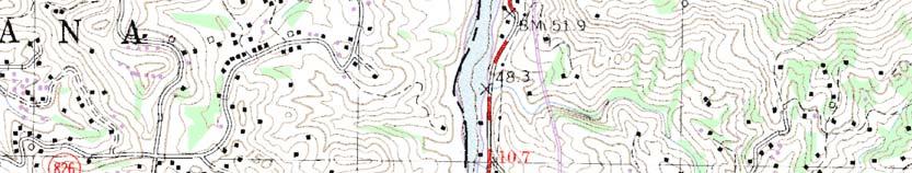
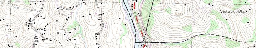
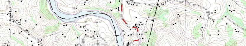
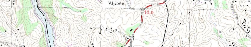
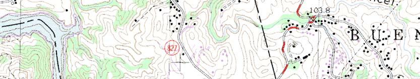
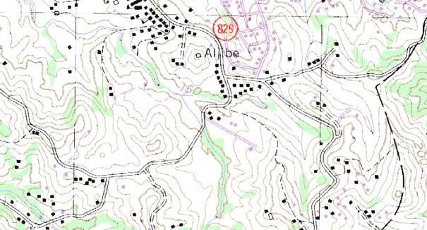
4 II. PROJECT BACKGROUND Location The project site is located at state road PR-167, Buena Vista Ward, in the Municipality of Bayamon. The project site is bordered by the PRHTA Parcel A on the north, Las Quintas Development on the south, Francisco Gastambide Vega School and state road PR-167 Road on the east, and Succession Ramos Vásquez on the west. Figure 1 shows the approximate location of the site in the USGS quadrangle. Figure 2 shows a layout of the proposed project. Topography Topography of the site shows slopes towards Quebrada Cancel. Ground elevation of the site varies between 125 and 105 m. referred to a local vertical control. Figure 3 shows the topography of the site. Water Bodies Quebrada Cancel is the only water body related to the site. This creek crosses the site from east to west. The project will not intend to affect neither the banks nor the bed of this watercourse. The project will be constructed outside of the 100-year flood footprint of the creek. Flooding From the regulatory point of view, the project site is not classified as floodable for a 100-year rainfall event. Figure 7 shows a portion of the FEMA flood insurance rate map Panel 705, revised on April
5 Field Work Field data used in this study was taken by the drawings provided by RAY Engineers. This information was used for the hydraulic modeling. Results obtained in this study are strictly based on this information. Fieldwork is attached in a pocket at the end of this study, as Appendix G. Former Studies No previous studies were found for this site. This study is based on the information provided by the engineer and gathered through site inspection and interviews of neighboring residents. Study Level This study is intended as an aid to the design engineer in the preparation of the construction drawings for the recommended structures. Figures, schematics and drawings must not be used as construction drawings. The design engineer must elaborate the construction drawings in agreement with the recommendations of this study. 4
6 III. HYDROLOGIC ANALYSIS Methodology The computer program entitled Flood Hydrograph Package (HEC-1) developed by the U.S. Army Corps of Engineers [1990] was used for the hydrologic analysis. Using this program, the Unit Hydrograph method and the Runoff Curve Number (CN) method, both developed by the Soil Conservation Service (SCS), were applied to determine the design hydrograph. This was computed by a process of translating the rainfall excess into a runoff hydrograph known as convolution. Peak discharges ranging in frequencies from 2, 10, 25, 50 and 100-year were estimated for existing and proposed condition. Drainage Areas From the topography, the project site drains to the watercourse. The project area shows to have four independent drainage areas at existing condition: Drainage area P1 with 4.50 acres, P2 with acres, P3 with 5.34 acres and P4 with Area P1 drain to two storm watercourses located to the northwest of the site. Areas P2, P3 and P4 drain to Quebrada Cancel. The four drainage areas have been essentially kept at proposed condition but area P2 has been subdivided in two areas; Drainage area P1 has 3.90 acres, P2A has 5.98 acres, P2B 7.50 acres, P acres and P4 has 7.15 acres. Seven offsite drainage areas contribute to Quebrada Cancel: E1 with 3.25 acres, E2 with acres, E3 with acres, E4 with acre, E5 with acres, E6 with acres, and E7 with acres. Offsite areas E4, E5, E6 and E7 were subdivided for the hydrologic computations. Figure 4 shows the drainage areas at existing condition and Figure 5 at proposed condition. 5
7 Curve Numbers Curve numbers were computed using the NRCS methodology. Soil types and land uses were gotten from SCS [1978] soil maps. According to the Soil Survey of San Juan Area of Puerto Rico, most of the soil of the project site was classified as Mucara clay (MxE) 20 to 40% slopes, and Mucara clay (MxD) 12 to 20% slopes. Soils at the offsite areas are Mucara clay (MxE) 20 to 40% slopes, and Mucara clay (MxD) 12 to 20% slopes, Naranjito silty clay (NaE2). Daguey clay (DaD) and Rio Arriba clay (RoC2). Weighted curve numbers for these soils were estimated. Curve Number of 93 was adopted for the developed area in consideration of the type of proposed land use. Appendix A shows the weighted Curve Number (CN) estimations and other physiographic characteristics of the drainage areas. Figure 6 shows the portion of the soil map corresponding to the area of study. Lag Time The lag time was estimated as sixty percent of the time of concentration as estimated by the formula of Kirpitch. Tc = L 0.77 /S where: L = channel length (ft) S = channel slope Tc = Time of concentration in min Detailed Lag Time calculations are shown in Appendix A. Rainfall Data The variation of rainfall volume with time was required as part of the storm input for the SCS Curve Number method. Therefore, the development of a design storm with a rainfall frequency 6
8 and duration was necessary to compute the design hydrograph for the watershed. Rainfall data used in this study was obtained from the Technical Paper No. 42 (TP-42) [National Weather Service, 1961]. The rainfall depths for 100, 50, 25, 10 and 2-years frequency for several durations was used and are shown in Table 1. Rainfall depths for 5 and 15 minutes duration were extrapolated by a regression analysis of the IDF curves. Table 1 Rainfall for 2, 10, 25, 50 y 100 years Precipitation Duration Inches Hrs. 2-yr 10-yr 25-yr 50-yr 100-yr Depth-Area Adjustment Point rainfall estimates obtained from the TP-42 represent values for areas up to 10 mi 2 ; therefore, a depth-area adjustment should be applied to the rainfall data when the watershed area is greater. In this case, the largest watershed is approximate 0.07 mi 2. Hence, this adjustment was not applied. 7
9 Time Distribution of Rainfall The triangular type methodology was used to distribute the rainfall depth in time. This method is considered acceptable for small areas. Rainfall Extraction Rainfall extraction such as the vegetative interception, the depressional storage, and the infiltration were estimated using the SCS's Runoff Curve Number method. Though this method is used to predict runoff volume directly, the rainfall extraction is incorporated in the model as function of the curve number of the watershed. Hydrologic Results Following HEC-1 methodology, hydrographs were determined for existing and proposed condition. Input and output data for the HEC-1 model are included in Appendix B for existing condition and Appendix C for proposed condition. Table 2 shows the results of the hydrologic analysis. 8
10 Table 2 Peak Discharges for and 100-yr Frequencies Peak Flow (cfs) CONDITION BASIN 2-yr 10-yr 25-yr EXISTING PROPOSED 50- yr 100-yr E E E7+E6+E E E7+E6+E5+E E E7+E6+E5+E4+E P E P E1+P E7+E6+E5+E4+E2+E1+P E P E7+E6+E5+E4+E2+E1+P4+P2+E3+P P E E E7+E6+E E E7+E6+E5+E E E7+E6+E5+E4+E P P2A P4+P2A E P2B E1+P2B E7+E6+E5+E4+E2+E1+P4+P E P E7+E6+E5+E4+E2+E1+P4+P2+E3+P P
11 From the inspection of Table 2, the peak discharge of the project site at proposed condition is higher than that of the existing condition at drainage areas P1, P2, P3 and P5; also the accumulated discharge at Quebrada Cancel. The increment in discharge has to be mitigated as required by Section of the Puerto Rico Planning Board Regulation No
12 IV. RUNOFF MITIGATION ANALYSIS The development of the site will increase the runoff discharge. The Puerto Rico Planning Board Regulation No. 3 requires a flow mitigation structure wherever an increase in discharge is produced. Therefore, a flow detention structures will be included in the project. One (1) detention pond was used: The pond will be located at drainage area P3. Figure 8 shows the location of this pond. The design engineer must provide the means to assure that the entire runoff of these areas discharges into the corresponding detention structure. The computer program HEC-1 provides the means for routing hydrographs through detention structures. Depth-Volume Relations The base area of the pond Pond will be 1,450 square meters and the side slopes 1V:2H. The Depth-Volume calculations for the pond were made under the assumption of a square base. Appendix D includes a spreadsheet with the depth-volume relation computations and the curve for the pond. 11
13 Flow Depth Relations The control structure for the pond will consist on one (1) 18 diameter orifice at the pond bottom, and a 20-feet wide rectangular weir located 2.3 meter above the bottom of the pond. Flow Depth relations for these structures were estimated taking into consideration discharges through orifices. Flow through the orifices was computed using Torrecelli s formula. Appendix D includes a spreadsheet with the depth-flow relation computations and its respective curve. Results Input and output data for the HEC-1 mitigation model are included in Appendix E. Table 3 shows the comparison of the discharges for existing, and proposed condition. 12
14 Table 3 Mitigation Analysis Results Comparison Peak Flow (cfs) CONDITION BASIN 2-yr 10-yr 25-yr EXISTING PROPOSED PROPOSED W/MITIGATION 50- yr 100-yr E E E7+E6+E E E7+E6+E5+E E E7+E6+E5+E4+E P E P E1+P E7+E6+E5+E4+E2+E1+P E P E7+E6+E5+E4+E2+E1+P4+P2+E3+P P E E E7+E6+E E E7+E6+E5+E E E7+E6+E5+E4+E P P2A P4+P2A E P2B E1+P2B E7+E6+E5+E4+E2+E1+P4+P E P E7+E6+E5+E4+E2+E1+P4+P2+E3+P P E E
15 E7+E6+E E E7+E6+E5+E E E7+E6+E5+E4+E P P2A P4+P2A E P2B E1+P2B POND E7+E6+E5+E4+E2+E1+P4+P E P E7+E6+E5+E4+E2+E1+P4+P2+E3+P P The results of the detention analysis show that the proposed detention pond provides appropriate runoff mitigation for the 100-year frequency discharge. Mitigation for 2-, 10-, 25- and 50-yr frequency peak discharges was also verified. 14
16 Runoff Mitigation Structure Dimensions and Accessories The maximum water stage at the tank for the 100-yr peak will be 2.36 m (7.76 ft). Final dimensions for the pond will include a minimum free board of 0.60 meters. Then, the detention pond will have the characteristics shown in Table 4. Table 4 Detention Tank Characteristics Dimensions Outlet Control Description Pond P3 Base Area, m2 1,450 Side Slope 1: 2 bottom, inches one-18" Weir 2.3 m above bottom 6.09 m Discharge Pipe One-36 ø For the mitigation analysis, the bottom geometry of the pond has been considered square but another shape can be used as well if the magnitude of the area is maintained. The pond has been located discharging above the 10-years water surface elevation at Cancel Creek. Figure 9 shows the schematics of the detention pond and the outlet accessories. 15
17 V. HYDRAULIC ANALYSIS A hydraulic analysis of Quebrada Cancel crossing the site has been made in order to find the water surface elevations and the extent of the 100-year footprint. This creek will not be affected by the project. The proposed pipe crossing will be made above the existing box culvert, therefore, way above the 100-year water surface elevation. The analysis was made by using the mathematical model HEC-RAS developed by the US Corps of Engineers. The friction coefficient used in the modeling was obtained from visual inspection of the existing structures; and cross-checked with the typical values provided by Barnes (1967) and Chow (1959). Manning s coefficient used for modeling the drainage system was for the natural watercourse and for the concrete structures. Contraction and Expansion Coefficients Coefficients of contraction and expansion used are those recommended by the HEC-RAS user s manual. Thus, coefficients of 0.1 and 0.3 respectively were used for gradual transitions. Hydraulic Run The geometry for the existing condition includes the natural watercourse across the site. The hydraulic analysis was made mainly for a 100-year discharge; but discharges for more recurrent storm events were also analyzed. Location of the cross sections used shown in Figure 10. Appendix F includes the analysis computer output. Table No. 5 shows the summary of the results. 16
18 Table 5: Results of the Hydraulic Run Reach River Sta Profile Q Total Min Ch El W.S. Elev Crit W.S. E.G. Elev E.G. Slope Vel Chnl Flow Area Top Width Froude #Chl (m3/s) (m) (m) (m) (m) (m/m) (m/s) (m2) (m) yrs yrs yrs yrs yrs yrs yrs yrs yrs yrs yrs yrs yrs yrs yrs yrs yrs yrs yrs yrs yrs yrs yrs yrs yrs yrs yrs yrs yrs yrs yrs yrs yrs yrs yrs
19 Flood Footprint With the results of the hydraulic analysis, a flood footprint has been drawn and is shown in Figure 11. The project will not affect the course of the creek. The toe of the fill, if any, will be located outside of the flood footprint. 18
20 VI. CONCLUSIONS AND RECOMMENDATIONS The following are the conclusions of this study: 1. According to the regulatory flood maps, the project site is not considered floodable for the 100-year rainfall event. 2. Proposed condition discharge is higher than that of the existing condition at areas P2 and P4. Runoff discharge mitigation is needed for each and all these areas. Different from them, discharge from area P1 does not increase; it can be discharge without a mitigation structure. 3. The proposed runoff mitigation pond reduces the local peak discharge to levels below the ones of the existing condition, as well as the overall discharge of Quebrada Cancel onto the downstream. The following are the recommendations of this study: 1. The project shall be constructed outside of the 100-year flood footprint. 2. Mitigation structure will have the dimensions and accessories indicated in Table 4 of this report. 3. The pipes must be installed to the elevations given in this study; any change found necessary must be subject to hydraulic verification. 4. It is very important to prepare a long-term maintenance plan, which should include the proposed pipes, the pond outlet structure and the receiving storm system inspection after each significant discharge events. Damages, if any, must be repaired promptly and properly. 19
21 Study Limits All the recommendations specified in this study must be considered to assure the optimum performance of the proposed discharge mitigation tank and receiving stream. The design engineer will be responsible for elaborating the drawings in conformance with the recommendations of this study. The results of this study are based on free flow conditions through the hydraulic structures. Proper maintenance must be developed to assure this condition. On the event of the occurrence of any severe obstruction to the flow, the results and recommendations may be impaired. Finally, results and recommendations included in this report must be used only and exclusively by the design engineer for the intended purposes as indicated in this study. 20
22 VII. BIBLIOGRAPHY National Weather Service, Generalized Estimates of Probable Maximum Precipitation and Rainfall Frequency Data for Puerto Rico and Virgin -Islands. Technical Paper No. 42. U.S. Department of Commerce. Washington, D.C.. P.R. Planning Board, Reglamento sobre Zonas Susceptibles a Inundaciones. Reglamento de Planificación Número 13. Estado Libre Asociado de Puerto Rico, Oficina del Gobernador. Soil Conservation Service, Soil Survey of San Juan Area of Puerto Rico. U.S. Department of Agriculture. U.S. Army Corps of Engineers, Flood Hydrograph Package (HEC-1), User's Manual. Hydrologic Engineering Center. Davis, California. 21
23 TABLE OF CONTENTS I. INTRODUCTION... 1 Purpose of Study... 1 Approach... 1 Authorization... 2 II. PROJECT BACKGROUND... 3 Location... 3 Topography... 3 Flooding... 3 Field Work... 4 Former Studies... 4 Study Level... 4 III. HYDROLOGIC ANALYSIS... 5 Methodology... 5 Drainage Areas... 5 Curve Numbers... 6 Lag Time... 6 Rainfall Data... 6 Depth-Area Adjustment... 7 Time Distribution of Rainfall... 8 Rainfall Extraction... 8 Hydrologic Results... 8 IV. RUNOFF MITIGATION ANALYSIS Depth-Volume Relations Flow Depth Relations Results Runoff Mitigation Structure Dimensions and Accessories i
24 V. HYDRAULIC ANALYSIS Contraction and Expansion Coefficients Hydraulic Run Flood Footprint VI. CONCLUSIONS AND RECOMMENDATIONS Study Limits VII. BIBLIOGRAPHY...21 ii
25 LIST OF FIGURES FIGURE 1. FIGURE 2. FIGURE 3. FIGURE 4. FIGURE 5. FIGURE 6. FIGURE 7. FIGURE 8. FIGURE 9. Location Map Proposed Development Layout Topography for Existing Condition Drainage Area at Existing Condition Drainage Area at Proposed Condition Soils Map FEMA Flood Insurance Rate Map Proposed Structures Layout Detention Pond Schematics FIGURE 10. Typical Detention Tank Schematics FIGURE 11. Location of the Cross Sections FIGURE years Flood Footprint iii
26 LIST OF APPENDIXES APPENDIX A. APPENDIX B. APPENDIX C. APPENDIX D. APPENDIX E. APPENDIX F. APPENDIX G. Hydrologic Parameters Estimation HEC-1 Results for Existing Condition HEC-1 Results or Proposed Condition Detention Structure Volume and Discharge to Depth Relations HEC-1 Results for Proposed Condition with Mitigation HEC-RAS Results for Existing Condition Field Work iv
27 FIGURES


28
29
30


31


32
33
HYDROLOGIC-HYDRAULIC STUDY ISABELLA OCEAN RESIDENCES ISLA VERDE, CAROLINA, PR
 HYDROLOGIC-HYDRAULIC STUDY ISABELLA OCEAN RESIDENCES ISLA VERDE, CAROLINA, PR 1 INTRODUCTION 1.1 Project Description and Location Isabella Ocean Residences is a residential development to be constructed
Hydrologic Study Report for Single Lot Detention Basin Analysis
 Hydrologic Study Report for Single Lot Detention Basin Analysis Prepared for: City of Vista, California August 18, 2006 Tory R. Walker, R.C.E. 45005 President W.O. 116-01 01/23/2007 Table of Contents Page
INFLOW DESIGN FLOOD CONTROL SYSTEM PLAN 40 C.F.R. PART PLANT YATES ASH POND 3 (AP-3) GEORGIA POWER COMPANY
 GEORGIA POWER COMPANY") INFLOW DESIGN FLOOD CONTROL SYSTEM PLAN 40 C.F.R. PART 257.82 PLANT YATES ASH POND 3 (AP-3) GEORGIA POWER COMPANY EPA s Disposal of Coal Combustion Residuals from Electric Utilities Final Rule (40 C.F.R.
INFLOW DESIGN FLOOD CONTROL SYSTEM PLAN 40 C.F.R. PART 257.82 PLANT YATES ASH POND 3 (AP-3) GEORGIA POWER COMPANY EPA s Disposal of Coal Combustion Residuals from Electric Utilities Final Rule (40 C.F.R.
INFLOW DESIGN FLOOD CONTROL SYSTEM PLAN PLANT BARRY ASH POND ALABAMA POWER COMPANY
 INFLOW DESIGN FLOOD CONTROL SYSTEM PLAN PLANT BARRY ASH POND ALABAMA POWER COMPANY Section 257.82 of EPA s regulations requires the owner or operator of an existing or new CCR surface impoundment or any
Jacobi, Toombs, and Lanz, Inc.
 Area 5: Blackiston Mill Road at Dead Man's Hollow Flooding Assessment Jacobi, Toombs, and Lanz, Inc. This document summarizes an assessment of drainage and flooding concerns and provides recommendations
INFLOW DESIGN FLOOD CONTROL SYSTEM PLAN 40 C.F.R. PART PLANT YATES ASH POND B (AP-B ) GEORGIA POWER COMPANY
 GEORGIA POWER COMPANY") INFLOW DESIGN FLOOD CONTROL SYSTEM PLAN 40 C.F.R. PART 257.82 PLANT YATES ASH POND B (AP-B ) GEORGIA POWER COMPANY EPA s Disposal of Coal Combustion Residuals from Electric Utilities Final Rule (40 C.F.R.
INFLOW DESIGN FLOOD CONTROL SYSTEM PLAN 40 C.F.R. PART 257.82 PLANT YATES ASH POND B (AP-B ) GEORGIA POWER COMPANY EPA s Disposal of Coal Combustion Residuals from Electric Utilities Final Rule (40 C.F.R.
Hydrologic Calibration:
 Hydrologic Calibration: UPDATE OF EFFECTIVE HYDROLOGY FOR MARYS CREEK October 2010 Agenda Background Hydrologic model Calibrated rainfall Hydrologic calibration 100 year discharges, Existing Conditions
Hydrology and Water Management. Dr. Mujahid Khan, UET Peshawar
 Hydrology and Water Management Dr. Mujahid Khan, UET Peshawar Course Outline Hydrologic Cycle and its Processes Water Balance Approach Estimation and Analysis of Precipitation Data Infiltration and Runoff
APPENDIX IV. APPROVED METHODS FOR QUANTIFYING HYDROLOGIC CONDITIONS OF CONCERN (NORTH ORANGE COUNTY)
") APPENDIX IV. APPROVED METHODS FOR QUANTIFYING HYDROLOGIC CONDITIONS OF CONCERN (NORTH ORANGE COUNTY) Hydromodification design criteria for the North Orange County permit area are based on the 2- yr, 24-hr
APPENDIX IV. APPROVED METHODS FOR QUANTIFYING HYDROLOGIC CONDITIONS OF CONCERN (NORTH ORANGE COUNTY) Hydromodification design criteria for the North Orange County permit area are based on the 2- yr, 24-hr
HYDROLOGIC MODELING CONSISTENCY AND SENSITIVITY TO WATERSHED SIZE
 HYDROLOGIC MODELING CONSISTENCY AND SENSITIVITY TO WATERSHED SIZE by James C.Y. Guo. Professor, Civil Engineering, U. Of Colorado at Denver, James.Guo@cudenver.edu.. And Eric Hsu, Project Engineer, Parson
INFLOW DESIGN FLOOD CONTROL SYSTEM PLAN 40 C.F.R. PART PLANT BOWEN ASH POND 1 (AP-1) GEORGIA POWER COMPANY
 GEORGIA POWER COMPANY") INFLOW DESIGN FLOOD CONTROL SYSTEM PLAN 40 C.F.R. PART 257.82 PLANT BOWEN ASH POND 1 (AP-1) GEORGIA POWER COMPANY EPA s Disposal of Coal Combustion Residuals from Electric Utilities Final Rule (40 C.F.R.
INFLOW DESIGN FLOOD CONTROL SYSTEM PLAN 40 C.F.R. PART 257.82 PLANT BOWEN ASH POND 1 (AP-1) GEORGIA POWER COMPANY EPA s Disposal of Coal Combustion Residuals from Electric Utilities Final Rule (40 C.F.R.
Chapter 6. Hydrology. 6.0 Introduction. 6.1 Design Rainfall
 6.0 Introduction This chapter summarizes methodology for determining rainfall and runoff information for the design of stormwater management facilities in the City. The methodology is based on the procedures
Summary of Detention Pond Calculation Canyon Estates American Canyon, California
 July 15, 2015 Bellecci & Associates, Inc Summary of Detention Pond Calculation Canyon Estates American Canyon, California 1. Methodology: Method: Unit Hydrograph Software: Bentley Pond Pack Version 8i
Project Drainage Report
 Design Manual Chapter 2 - Stormwater 2A - General Information 2A-4 Project Drainage Report A. Purpose The purpose of the project drainage report is to identify and propose specific solutions to stormwater
Overview of NRCS (SCS) TR-20 By Dr. R.M. Ragan
 TR-20 By Dr. R.M. Ragan") Overview of NRCS (SCS) TR-20 By Dr. R.M. Ragan TR-20 is a computer program for the simulation of runoff occurring from a single storm event. The program develops flood hydrographs from runoff and routes
Overview of NRCS (SCS) TR-20 By Dr. R.M. Ragan TR-20 is a computer program for the simulation of runoff occurring from a single storm event. The program develops flood hydrographs from runoff and routes
SAN GORGONIO PASS CAMPUS - PHASE I
 SAN GORGONIO PASS CAMPUS - PHASE I Banning, CA DRAINAGE STUDY June 16, 2010 Reference 106-195 PREPARED BY: Encompass Associates, Inc. 5699 Cousins Place Rancho Cucamonga, CA 91737 909-684-0093 Fax-909-586-6979
CHAPTER 3 STORMWATER HYDROLOGY. Table of Contents SECTION 3.1 METHODS FOR ESTIMATING STORMWATER RUNOFF
 CHAPTER 3 STORMWATER HYDROLOGY Table of Contents SECTION 3.1 METHODS FOR ESTIMATING STORMWATER RUNOFF 3.1.1 Introduction to Hydrologic Methods...3.1-1 3.1.2 Symbols and Definitions...3.1-3 3.1.3 Rainfall
Rainfall, Runoff and Peak Flows: Calibration of Hydrologic Design Methods for the Kansas City Area
 Rainfall, Runoff and Peak Flows: Calibration of Hydrologic Design Methods for the Kansas City Area Bruce McEnroe, Bryan Young, Ricardo Gamarra and Ryan Pohl Department of Civil, Environmental, and Architectural
The Islamic University of Gaza- Civil Engineering Department Sanitary Engineering- ECIV 4325 L5. Storm water Management
 The Islamic University of Gaza- Civil Engineering Department Sanitary Engineering- ECIV 4325 L5. Storm water Management Husam Al-Najar Storm water management : Collection System Design principles The Objectives
iswm TM Technical Manual Hydrology:
 : 1.0 2.0 Downstream Assessment 3.0 Streambank Protection 4.0 Water Balance 5.0 Rainfall Tables 6.0 Hydrologic Soils Data Table of Contents 1.0... HO-1 1.1 Estimating Runoff... HO-1 1.1.1 Introduction
1 n. Flow direction Raster DEM. Spatial analyst slope DEM (%) slope DEM / 100 (actual slope) Flow accumulation
 slope DEM / 100 (actual slope) Flow accumulation") 1 v= R S n 2/3 1/2 DEM Flow direction Raster Spatial analyst slope DEM (%) Flow accumulation slope DEM / 100 (actual slope) 0 = no cell contributing 215 = 215 cell contributing towards that cell sqrt (actual
1 v= R S n 2/3 1/2 DEM Flow direction Raster Spatial analyst slope DEM (%) Flow accumulation slope DEM / 100 (actual slope) 0 = no cell contributing 215 = 215 cell contributing towards that cell sqrt (actual
Culvert Sizing procedures for the 100-Year Peak Flow
 CULVERT SIZING PROCEDURES FOR THE 100-YEAR PEAK FLOW 343 APPENDIX A: Culvert Sizing procedures for the 100-Year Peak Flow A. INTRODUCTION Several methods have been developed for estimating the peak flood
DRAINAGE & DESIGN OF DRAINAGE SYSTEM
 Drainage on Highways DRAINAGE & DESIGN OF DRAINAGE SYSTEM P. R.D. Fernando Chartered Engineer B.Sc.(Hons), M.Eng. C.Eng., MIE(SL) Drainage Requirement of Highway Drainage System Introduction Drainage means
Activity Calculating Property Drainage
 Page 1 of 5 Activity 2.3.11 Calculating Property Drainage Introduction When a property is developed, it is important to understand that changes to watershed characteristics (i.e., land use, slope, soil
Runoff Hydrographs. The Unit Hydrograph Approach
 Runoff Hydrographs The Unit Hydrograph Approach Announcements HW#6 assigned Storm Water Hydrographs Graphically represent runoff rates vs. time Peak runoff rates Volume of runoff Measured hydrographs are
PRELIMINARY HYDROLOGY/HYDRAULICS ANALYSES RESULTS
 PRELIMINARY HYDROLOGY/HYDRAULICS ANALYSES RESULTS Coldstream Park Stream Corridor Restoration and Preservation Consent Decree SEP Prepared for Lexington-Fayette Urban County Government Division of Water
HYDROLOGY STUDY PREPARED FOR: MARKHAM PERRIS LLC 302 WEST FIFTH STREET, SUITE 103 SAN PEDRO, CA (310) FOR THE PROJECT:
 FOR THE PROJECT:") HYDROLOGY STUDY PREPARED FOR: MARKHAM PERRIS LLC 302 WEST FIFTH STREET, SUITE 103 SAN PEDRO, CA 90731 (310) 241-2992 FOR THE PROJECT: PERRIS VALLEY COMMERCE CENTER BUILDING PERRIS, CALIFORNIA PROJECT NUMBER:
HYDROLOGY STUDY PREPARED FOR: MARKHAM PERRIS LLC 302 WEST FIFTH STREET, SUITE 103 SAN PEDRO, CA 90731 (310) 241-2992 FOR THE PROJECT: PERRIS VALLEY COMMERCE CENTER BUILDING PERRIS, CALIFORNIA PROJECT NUMBER:
INFLOW DESIGN FLOOD CONTROL SYSTEM PLAN 40 C.F.R. PART PLANT DANIEL ASH POND B MISSISSIPPI POWER COMPANY
 INFLOW DESIGN FLOOD CONTROL SYSTEM PLAN 40 C.F.R. PART 257.82 PLANT DANIEL ASH POND B MISSISSIPPI POWER COMPANY EPA s Disposal of Coal Combustion Residuals from Electric Utilities Final Rule (40 C.F.R.
New Castle County, DE. Floodplain Regulations
 New Castle County, DE Floodplain Regulations John J. Gysling, PE CFM Department of Land Use New Castle County, DE February 26, 2009 Today s Presentation Floodplain Protection and Uses Terms and Definitions
PRELIMINARY DRAINAGE REPORT NEWCASTLE FIRE STATION OLD STATE HIGHWAY
 PRELIMINARY DRAINAGE REPORT FOR THE NEWCASTLE FIRE STATION OLD STATE HIGHWAY PREPARED FOR THE NEWCASTLE FIRE PROTECTION DISTRICT JULY 2014 BY ROSEVILLE DESIGN GROUP, INC. ROSEVILLE DESIGN GROUP, Inc Established
Appendix VI: Illustrative example
 Central Valley Hydrology Study (CVHS) Appendix VI: Illustrative example November 5, 2009 US Army Corps of Engineers, Sacramento District Prepared by: David Ford Consulting Engineers, Inc. Table of contents
Chapter 4. Drainage Report and Construction Drawing Submittal Requirements
 4.0 Introduction The requirements presented in this section shall be used to aid the design engineer or applicant in the preparation of drainage reports, drainage studies, and construction drawings for
DRAFT. Jacob Torres, P.E.; Nick Fang, Ph.D., P.E.
 \ Memorandum SSPEED Center at Rice University Department of Civil & Environmental Engineering 6100 Main MS-317 Houston, Texas 77005-1827 sspeed.rice.edu tel: 713-348-4977 To Andy Yung, P.E. CFM; Lane Lease,
Chapter H. Introduction to Surface Water Hydrology and Drainage for Engineering Purposes
 Chapter H. Introduction to Surface Water Hydrology and Drainage for Engineering Purposes As seen in Figure H.1, hydrology is a complex science that deals with the movement of water between various stages
Stormwater Management Studies PDS Engineering Services Division ES Policy # 3-01
 Stormwater Management Studies PDS Engineering Services Division Revised Date: 2/28/08 INTRODUCTION The City of Overland Park requires submission of a stormwater management study as part of the development
5/11/2007. WinTR-55 for Plan Reviews Small Watershed Hydrology Overview
 WinTR-55 for Plan Reviews Small Watershed Hydrology Overview 1 Overview Course Outline Historical Background Program Description Model Capabilities and Limitations This is the Overview portion of the training.
Peak discharge computation
 Ia/P 4 Peak Dischage Method Graphical Peak Discharge Method This chapter presents the Graphical Peak Discharge method for computing peak discharge from rural and urban areas. The Graphical method was developed
Appendix G Preliminary Hydrology Study
 Appendix G Preliminary Hydrology Study Preliminary Hydrology Study VESTING TTM 72608 Long Beach, CA Prepared for: The Long Beach Project, LLC 888 San Clemente, Suite 100 New Port Beach, CA May 28, 2014
Ponds. Pond A water impoundment made by excavating a pit, or constructing a dam or an embankment.
 POND SITE SELECTION AND CONSTRUCTION Uses, Planning, & Design David Krietemeyer Area Engineer USDA-NRCS June 20, 2008 Uses Considerations for Location of Commonly Used Terms Pond A water impoundment made
EART 204. Water. Dr. Slawek Tulaczyk. Earth Sciences, UCSC
 EART 204 Water Dr. Slawek Tulaczyk Earth Sciences, UCSC 1 Water is an amazing liquid, (high heat capacity - particularly in phase transitions, maximum density at ca. 4 deg. C) 2 3 4 5 6 7 8 9 Basin Hydrologic
Standards for Soil Erosion and Sediment Control in New Jersey May 2012 STANDARD FOR SLOPE PROTECTION STRUCTURES. Definition
 STANDARD FOR SLOPE PROTECTION STRUCTURES Definition Structures to safely conduct surface runoff from the top of a slope to the bottom of the slope. Purpose The purpose of this practice is to convey storm
Engineering Hydrology. Class 16: Direct Runoff (DRO) and Unit Hydrographs
 and Unit Hydrographs") Engineering Hydrology Class 16: and s Topics and Goals: 1. Calculate volume of DRO from a hydrograph; 2. Complete all steps to develop a. Class 14: s? HG? Develop Ocean Class 14: s? HG? Develop Timing
Engineering Hydrology Class 16: and s Topics and Goals: 1. Calculate volume of DRO from a hydrograph; 2. Complete all steps to develop a. Class 14: s? HG? Develop Ocean Class 14: s? HG? Develop Timing
DRAINAGE PLAN OF NAU S EASTBURN EDUCATION AND GAMMAGE BUILDINGS FINAL PROPOSAL
 MAY 10, 2016 DRAINAGE PLAN OF NAU S EASTBURN EDUCATION AND GAMMAGE BUILDINGS FINAL PROPOSAL Connor Klein, Jiangnan Yi, Yuzhi Zhang, Yi Yang NORTHERN ARIZONA UNIVERSITY NAU Water Buffalo Engineering Table
Municipal Stormwater Ordinances Summary Table
 APPENDIX F Municipal Ordinances Summary Table Municipality Abington Bryn Athyn Borough Hatboro Borough Ordinance, SALDO Runoff equals pre post Erosion Sediment Control Water Quality Requirements Any which
Appendix B. Storm Drain System Data
 MENIFEE VALLEY CAMPUS MASTER PLAN FINAL EIR MT. SAN JACINTO COMMUNITY COLLEGE DISTRICT Appendix Appendix B. Storm Drain System Data June 2017 MENIFEE VALLEY CAMPUS MASTER PLAN FINAL EIR MT. SAN JACINTO
Index. Page numbers followed by f indicate figures.
 Index Aerodynamic method, 103, 110 111 Algae, 131, 173, 175 Alternate depth, 88 Alternating block method, 132, 140 141 Attenuation, 106, 107f, 118, 120 Page numbers followed by f indicate figures. Baseflow
Rainfall - runoff: Unit Hydrograph. Manuel Gómez Valentín E.T.S. Ing. Caminos, Canales y Puertos de Barcelona
 Rainfall - runoff: Unit Hydrograph Manuel Gómez Valentín E.T.S. ng. Caminos, Canales y Puertos de Barcelona Options in many commercial codes,, HMS and others HMS Menu Transform method, User specified,
Inflow Design Flood Control System Plan for Louisa Generating Station CCR Impoundment. MidAmerican Energy Company
 Control System Plan for Louisa Generating Station CCR Impoundment MidAmerican Energy Company October 10, 2016 Control System Plan for Louisa Generating Station CCR Impoundment Prepared for MidAmerican
CONVEYANCE ANALYSIS OF THE MAINLINE TUNNEL USING ICAP
 VEN TE CHOW HYDROSYSTEMS LAB Technical Memorandum CONVEYANCE ANALYSIS OF THE MAINLINE TUNNEL USING ICAP David S. Ancalle Nils Oberg Marcelo H. García Ven Te Chow Hydrosystems Laboratory Dept. of Civil
Hydrology Study. Ascension Heights Subdivision Ascension Drive at Bel Aire Road San Mateo, California (Unincorporated)
") Hydrology Study Ascension Heights Subdivision Ascension Drive at Bel Aire Road San Mateo, California (Unincorporated) Prepared for San Mateo Real Estate & Construction March 9, 21 Rev. 1 11-8-211 Rev.
Hydrology Study Ascension Heights Subdivision Ascension Drive at Bel Aire Road San Mateo, California (Unincorporated) Prepared for San Mateo Real Estate & Construction March 9, 21 Rev. 1 11-8-211 Rev.
Engineering Hydrology Class 3
 Engineering Hydrology Class 3 Topics and Goals: I.Develop s (estimate precipitation) II.Develop simple constant intensity design storm III.Develop SCS design storm Ocean s Why do we want to derive the?
HYDROLOGIC & HYDRAULIC ASPECTS of the Walnut Street Bridge over the Schuylkill River Philadelphia, PA
 HYDROLOGIC & HYDRAULIC ASPECTS of the Walnut Street Bridge over the Schuylkill River Philadelphia, PA J. Richard Weggel CAEE201 Lectures 30 April & 2 May 2007 HYDROLOGY (Natural Science) Study of the waters
HYDROLOGY STUDY LA MIRADA BOULEVARD La Mirada, California
 HYDROLOGY STUDY 12000 LA MIRADA BOULEVARD La Mirada, California TTM 73119 Prepared for: The Olson Company 3010 Old Ranch Parkway, Suite 100 Seal Beach, CA 90740 Contact: Mr. Aaron Orenstein (562) 370-9531
HYDROLOGY REPORT HEACOCK & CACTUS CHANNELS MORENO VALLEY, CALIFORNIA NOVEMBER 2005 REVISED APRIL 2006 REVISED AUGUST 2006
 HYDROLOGY REPORT HEACOCK & CACTUS CHANNELS MORENO VALLEY, CALIFORNIA NOVEMBER 2005 REVISED APRIL 2006 REVISED AUGUST 2006 RIVERSIDE COUNTY FLOOD CONTROL AND WATER CONSERVATION DISTRICT TABLE OF CONTENTS
1. Stream Network. The most common approach to quantitatively describing stream networks was postulated by Strahler (1952).
.") 1. Stream Network The most common approach to quantitatively describing stream networks was postulated by Strahler (1952). First Order Streams streams with no tributaries. Second Order Streams begin at
1. Stream Network The most common approach to quantitatively describing stream networks was postulated by Strahler (1952). First Order Streams streams with no tributaries. Second Order Streams begin at
APPENDIX G HYDRAULIC GRADE LINE
 Storm Drainage 13-G-1 APPENDIX G HYDRAULIC GRADE LINE 1.0 Introduction The hydraulic grade line is used to aid the designer in determining the acceptability of a proposed or evaluation of an existing storm
CLARK COUNTY REGIONAL FLOOD CONTROL DISTRICT HYDROLOGIC CRITERIA AND DRAINAGE DESIGN MANUAL
 CLARK COUNTY REGIONAL FLOOD CONTROL DISTRICT HYDROLOGIC CRITERIA AND DRAINAGE DESIGN MANUAL SECTION 600 STORM RUNOFF TABLE OF CONTENTS 601 INTRODUCTION 603 601.1 - Basin Characteristics 603 602 TIME OF
Stormwater Local Design Manual For Houston County, Georgia
 Stormwater Local Design Manual For Houston County, Georgia Adopted November 15, 2005 TABLE OF CONTENTS 1. FORWARD... 1 2. GENERAL LEVEL OF SERVICE STANDARDS... 2 2.1. DETENTION REQUIREMENTS... 2 2.1.1.
6.0 Runoff. 6.1 Introduction. 6.2 Flood Control Design Runoff
 October 2003, Revised February 2005 Chapter 6.0, Runoff Page 1 6.1 Introduction 6.0 Runoff The timing, peak rates of discharge, and volume of stormwater runoff are the primary considerations in the design
Sizing Calculations and Design Considerations for LID Treatment Measures
 SCVURPPP C.3 Workshop December 18, 2012 Sizing Calculations and Design Considerations for LID Treatment Measures Jill Bicknell, P.E., EOA, Inc. Santa Clara Valley Urban Runoff Pollution Prevention Program
The Texas A&M University and U.S. Bureau of Reclamation Hydrologic Modeling Inventory (HMI) Questionnaire
 Questionnaire") The Texas A&M University and U.S. Bureau of Reclamation Hydrologic Modeling Inventory (HMI) Questionnaire May 4, 2010 Name of Model, Date, Version Number Dynamic Watershed Simulation Model (DWSM) 2002
The Texas A&M University and U.S. Bureau of Reclamation Hydrologic Modeling Inventory (HMI) Questionnaire May 4, 2010 Name of Model, Date, Version Number Dynamic Watershed Simulation Model (DWSM) 2002
MODEL Stormwater Local Design Manual. City of Centerville
 MODEL Stormwater Local Design Manual City of Centerville Adopted December 6, 2005 TABLE OF CONTENTS 1. FORWARD... 1 2. GENERAL LEVEL OF SERVICE STANDARDS... 1 2.1. DETENTION REQUIREMENTS... 1 2.1.1. Discharge
Lyon Creek Cedar Way Stormwater Detention Dam Operation and Maintenance Manual
 Lyon Creek Cedar Way Stormwater Detention Dam Operation and Maintenance Manual Prepared by: Mike Shaw Stormwater Program Manager City of Mountlake Terrace January 2010 Section I General Information This
December 7, Dr. Christine Pomeroy University of Utah Civil and Environmental Engineering MCE Salt Lake City, UT. Dear Dr.
 December 7, 2012 Dr. Christine Pomeroy University of Utah Civil and Environmental Engineering MCE 2042 Salt Lake City, UT 84112 Dear Dr. Pomeroy, The following document is the final report of the Red Butte
Software Applications for Runoff Hydrological Assessment
 Bulletin UASVM Horticulture, 67(2)/2010 Print ISSN 1843-5254; Electronic ISSN 1843-5394 Software Applications for Runoff Hydrological Assessment Severin CAZANESCU 1), Sorin CIMPEANU 1), Oana GUI 2), Dana
Norman Maclean Snowmelt Flow rate Storm flows fs (c flow m a tre S
 Eventually, all things merge into one, and a river runs through it. Norman Maclean Understanding Streamflow ADEQ SW Short Course June 13, 213 Phoenix, AZ Hydrographs Discharge (Q) USGS flow data & plots
HYDROLOGIC CONSIDERATIONS. 22 nd Annual Nonpoint Source Pollution Conference Saratoga Springs, NY
 LOW IMPACT DEVELOPMENT HYDROLOGIC CONSIDERATIONS 22 nd Annual Nonpoint Source Pollution Conference Saratoga Springs, NY May 18, 2011 PRESENTATION AGENDA Introduction Definitions Discuss Impacts to Hydrologic
NEW CASTLE CONSERVATION DISTRICT. through. (Name of Municipality) PLAN REVIEW APPLICATION DRAINAGE, STORMWATER MANAGEMENT, EROSION & SEDIMENT CONTROL
 PLAN REVIEW APPLICATION DRAINAGE, STORMWATER MANAGEMENT, EROSION & SEDIMENT CONTROL") NEW CASTLE CONSERVATION DISTRICT through (Name of Municipality) PLAN REVIEW APPLICATION DRAINAGE, STORMWATER MANAGEMENT, EROSION & SEDIMENT CONTROL Office use only: Received by Municipality: Received by
NEW CASTLE CONSERVATION DISTRICT through (Name of Municipality) PLAN REVIEW APPLICATION DRAINAGE, STORMWATER MANAGEMENT, EROSION & SEDIMENT CONTROL Office use only: Received by Municipality: Received by
DRAINAGE CRITERIA MANUAL (V. 1) RUNOFF
 RUNOFF") Section CONTENTS Page RO- 1.0 OVERVIEW... 1 2.0 RATIONAL METHOD... 3 2.1 Rational Formula... 3 2.2 Assumptions... 4 2.3 Limitations... 4 2.4 Time of Concentration... 5 2.4.1 Initial Flow Time... 5 2.4.2
Section CONTENTS Page RO- 1.0 OVERVIEW... 1 2.0 RATIONAL METHOD... 3 2.1 Rational Formula... 3 2.2 Assumptions... 4 2.3 Limitations... 4 2.4 Time of Concentration... 5 2.4.1 Initial Flow Time... 5 2.4.2
PART 3 - STANDARDS FOR SEWERAGE FACILITIES DESIGN OF STORM SEWERS
 PART 3 - STANDARDS FOR SEWERAGE FACILITIES 3.3 - DESIGN OF STORM SEWERS 3.301 Design of Storm Sewers A. General Information B. Investigations and Surveys C. Special Projects 3.302 Design Criteria for Storm
DIVISION 5 STORM DRAINAGE CRITERIA
 DIVISION 5 STORM DRAINAGE CRITERIA Section 5.01 GENERAL The following storm drainage design criteria shall apply to all storm drainage designs in the City. Additional design criteria are specified in the
Treatment Volume: Curve Numbers. Composite CN or Not? Treatment Volume: Curve Numbers. Treatment Volume: Calculation. Treatment Volume: Calculation
 Stormwater Engineering Bioretention Design Bill Hunt, PE, Ph.D. Extension Specialist & Assistant Professor NCSU-BAE www.bae.ncsu.edu/stormwater Bioretention Design Six Step Process 1 Determine Volume to
STORMWATER RUNOFF AND WATER QUALITY IMPACT REVIEW
 SUBCHAPTER 8 STORMWATER RUNOFF AND WATER QUALITY IMPACT REVIEW 7:45-8.1 Purpose and scope of review Except for those projects expressly exempted by this chapter or waived by the Commission, the Commission
SITE DESIGN ENGINEERING, LLC. 11 Cushman Street, Middleboro, MA P: F:
 INTRODUCTION This drainage report was prepared for the proposed site re-development at in Burlington, Massachusetts. The project site is approximately 1.05± acres consisting of approximately 70% impervious
OFFICE OF STRUCTURES MANUAL ON HYDROLOGIC AND HYDRAULIC DESIGN CHAPTER 3 POLICY AND PROCEDURES
 OFFICE OF STRUCTURES MANUAL ON HYDROLOGIC AND HYDRAULIC DESIGN CHAPTER 3 POLICY AND PROCEDURES April 28, 2016 Table of Contents 3.1 Introduction... 2 3.1.1 Purpose of Chapter 3... 2 3.1.2 Policy vs. Design
Rhode Island Stormwater Design and Installations Standards Manual
 Rhode Island Stormwater Design and Installations Standards Manual Public Workshop Required Management Volume Calculations and Redevelopment Considerations March 22, 2011 Presentation Outline Recap of How
INFLOW DESIGN FLOOD CONTROL SYSTEM PLAN. Bremo Power Station CCR Surface Impoundment: North Ash Pond INFLOW DESIGN FLOOD
 INFLOW DESIGN FLOOD CONTROL SYSTEM PLAN INFLOW DESIGN FLOOD CONTROL SYSTEM PLAN Bremo Power Station CCR Surface Impoundment: North Ash Pond Submitted To: Bremo Power Station 1038 Bremo Bluff Road Bremo
City of Oakland. Public Works Agency Standards STORM DRAINAGE DESIGN GUIDELINES. Engineering Design & ROW Management Division
 City of Oakland PUBLIC WORKS AGENCY 250 FRANK H. OGAWA PLAZA 4 TH FLOOR OAKLAND, CALIFORNIA 94612 (510) 238-3437 FAX (510) 238-7227 TTD (510) 238-3254 Public Works Agency Standards STORM DRAINAGE DESIGN
Section 600 Runoff Table of Contents
 Section 600 Runoff Table of Contents 601 INTRODUCTION...600-1 602 RATIONAL METHOD...600-1 602.1 Rational Method Formula...600-2 602.2 Time of Concentration...600-2 602.3 Intensity...600-4 602.4 Runoff
Pre-Treatment Bioretention Cells Bioswales IOWA STORMWATER MANAGEMENT MANUAL DECEMBER 16, 2015
 Pre-Treatment Bioretention Cells Bioswales IOWA STORMWATER MANAGEMENT MANUAL DECEMBER 16, 2015 Urban Runoff Background How we got here What Problem?? Provenance of the Problem Unified Sizing Criteria What
City of Morristown. Stormwater Program Standard Operating Procedures. Stormwater Design Guidance Manual. April 1, 2016.
 City of Morristown Stormwater Program Standard Operating Procedures Stormwater Design Guidance Manual April 1, 2016 -Prepared By- City of Morristown 100 West First North Street Morristown, TN 37814 (423)
Inflow Design Flood Control System Plan
 Inflow Design Flood Control System Plan For Compliance with the Coal Combustion Residuals Rule (40 CFR Part 257) Cherokee Station - CCR Surface Impoundments Public Service Company of Colorado Denver, Colorado
STORM DRAINAGE DESIGN CRITERIA
 BWM Orig. 01/01/05 Revised 01/01/10 LUCAS COUNTY ENGINEERS OFFICE STORM DRAINAGE DESIGN CRITERIA Drainage The design of storm sewer systems will be based upon the Rational Method using the equation Q=CiA
Suspended Sediment Discharges in Streams
 US Army Corps of Engineers Hydrologic Engineering Center Suspended Sediment Discharges in Streams April 1969 Approved for Public Release. Distribution Unlimited. TP-19 REPORT DOCUMENTATION PAGE Form Approved
Pennsylvania Stormwater Best Management Practices Manual. Section 3 Stormwater Management Principles, Goals, and a Management Model
 Pennsylvania Stormwater Best Management Practices Manual DRAFT - JANUARY 2005 Section 3 Stormwater Management Principles, Goals, and a Management Model This page intentionally left blank. Section 3 Stormwater
RE: Final Drainage Letter: Northwest Aurora Alley Improvements 2016
 April 12, 2016 Mr. Craig Perl, P.E. Senior Engineer City of Aurora Public Works Department 15151 E. Alameda Parkway Aurora, CO 80012 RE: Final Drainage Letter: Northwest Aurora Alley Improvements 2016
ATTACHMENT 4: Design Calculations and Construction Details
 Pennsylvania Pipeline Project Erosion and Sediment Control Plan Southeast Region: Spread 6 November 2016 ATTACHMENT 4: Design Calculations and Construction Details Tetra Tech Pennsylvania Pipeline Project
Run-On and Run-Off Control System Plan Neal North Energy Center Monofill
 Run-On and Run-Off Control System Plan Neal North Energy Center Monofill MidAmerican Energy Company, Neal North Energy Center Coal Combustion Residual Rule Compliance October 10, 2016 Run-On and Run-Off
Initial Inflow Design Flood Control System Plan
 Initial Inflow Design Flood Control System Plan Brunner Island Ash Basin No. 6 Prepared for: Brunner Island, LLC October 11, 2016 This page intentionally left blank. Initial Inflow Design Flood Control
CEE3430 Engineering Hydrology
 CEE3430 Engineering Hydrology Practice Exam (There are multiple practice questions here A 110 min test will likely not have more than four questions) 1. Water Balance Write the water balance as Δ Where
iswm TM Criteria Manual City of Azle Section 14 City of Azle Subdivision Ordinance DRAFT-June Chapter 1
 City of Azle Section 14 City of Azle Subdivision Ordinance DRAFT-June 2010... Chapter 1 i CITY OF AZLE iswm CRITERIA MANUAL FOR SITE DEVELOPMENT AND CONSTRUCTION Incorporating the Regional NCTCOG Integrated
Outlet Structure Modeling
 Watershed Modeling using HEC-RAS Outlet Structure Modeling Jeff Wickenkamp, P.E., CFM, D.WRE Patrick Lach, P.E. Hey and Associates, Inc. Water Resources, Wetlands and Ecology Outline of Presentation Why
FIRM NAME DESIGNER: CHECKER: DATE: FPID #: DESCRIPTION: COUNTY: DRAINAGE DESIGN CHECKLIST. Designers Initials. Checkers Initials.
 I. Drainage Report A. Executive Summary - Brief Overview of Project Drainage Design B. Project Description 1. Existing Conditions 2. Proposed Project Conditions 3. Project Justification Narrative - Basin
City of Tulsa. Stormwater Design Criteria Manual
 City of Tulsa Stormwater Design Criteria Manual 2014 Table of Contents Chapter 100 EXECUTIVE SUMMARY... 101 101 INTRODUCTION... 101 101.1 Manual Organization... 101 101.2 Manual Contents... 101 101.2.1
San Antonio Water System Mitchell Lake Constructed Wetlands Below the Dam Preliminary Hydrologic Analysis
 San Antonio Water System enhancement. This recommendation was based on limited water quality data provided by SAWS and using a free-water surface constructed wetland with approximately 112 acres of wetted
Appendix D - Evaluation of Interim Solutions
 Appendix D - Evaluation of Interim Solutions D.1 Introduction The implementation of long-term improvements is projected to take 5 to 8 years. To reduce the number of years of flooding impacts, the partner
GRASS-LINED CHANNEL (acre) CODE 840
 CODE 840") NATURAL RESOURCES CONSERVATION SERVICE ILLINOIS URBAN MANUAL PRACTICE STANDARD GRASS-LINED CHANNEL (acre) CODE 840 (Source: NC Erosion and Sediment Control Field Manual) DEFINITION A natural or constructed
NATURAL RESOURCES CONSERVATION SERVICE ILLINOIS URBAN MANUAL PRACTICE STANDARD GRASS-LINED CHANNEL (acre) CODE 840 (Source: NC Erosion and Sediment Control Field Manual) DEFINITION A natural or constructed
Hydraulic Design of Highway Culverts HDS 5 September 1985
 Hydraulic Design of Highway Culverts HDS 5 September 1985 Welcome to HDS 5 - Hydraulic Design of Highway Culverts Table of Contents Preface Tech Doc U.S. - SI Conversions DISCLAIMER: During the editing
Volume 2, Chapter 10 - Storage
 Volume 2, Chapter 10 - Storage Users Guidance: If a UDFCD Section number in this chapter is skipped: It was adopted as is; please refer to that Section in the corresponding UDFCD Manual, Volume, Chapter