Specification Section Title Notation A Product Data Approved as Noted B Shop Drawings Approved as Noted
|
|
|
- Bernice Holland
- 6 years ago
- Views:
Transcription
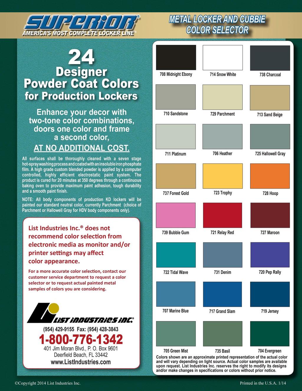
1 Submittal Review TO: Pavilion Construction DATE: JOB NO.: 1484P 4700 SW Macadam Ave Suite 200 ATTENTION: Riley Tobin Portland, OR RE: BSD Sunset High School Concession Stand/Interior Renovations Package 1 Submittal: Metal Lockers Approved Approved As Noted Revise as Noted/Resubmit Rejected/Resubmit As Specified No Action Required Submittal Not Requested/Returned Without Review Approval is for conformance with information given and the design concept expressed in the Contract Documents. Contractor is responsible for quantities and dimensions to be confirmed and correlated; for fabrication process; for means methods, techniques, sequences and procedures of construction; for coordination of the Work; and for all safety aspects of performing the Work. Approval does not modify the Contract Documents and approval of a specific item does not indicate approval of an assembly of which the item is a component. Specification Section Title Notation A Product Data Approved as Noted B Shop Drawings Approved as Noted C Samples For Each Color Selected Approved as Noted. See note D Samples For Initial Selection Approved as Noted E Samples For Verification Not Submitted. Resubmit F Product Schedule Reviewed in Submittal A Qualification Data Reviewed in Submittal B Sample Warranty Reviewed in Submittal Summary Comments: 1. G.C. to verify all dimensions and Locations. 2. See the attached pdf for additional comments. 3. Beaverton School District has selected color #706 Heather. 4. Locker type B K.D. construction is acceptable per Jessica Faust of BSD. 5. See previous locker submittal for approved numbering scheme. 6. See page # SB for comment on filler panel dimensions SW 5 th Ave. // Suite 1100 // Portland // OR // P: //
2 Sunset High School NW Cornell Rd. Portland, OR To: Attn: BLRB ARCHITECTS, P.S. RICHARD HIGGINS 1001 SW 5TH AVE., SUITE 1100 PORTLAND, OR Date: Contact Phone: Contact 07/09/ CC d: SUBMITTAL TRANSMITTAL FOR APPROVAL Submittal #: 42 Rev.#: 1 In Accordance with Specification Section #: This is a submittal for Metal Lockers items per the table below as reviewed and noted by Pavilion Construction NW, LLC, and provided by. Please provide a response to this submittal by 07/13/2015. Pavilion Status: Sent/Submitted Notes: Submitted By: Address: Riley Tobin rtobin@pavilionconstruction.com Phone: Fax: (503) (503) SUBMITTAL RESPONSE Architect s Response Schedule Tracking Proceed Proceed, as noted Revise and Resubmit Material Return without Review Date Date Date Date Received from Sub/Sup Requested to be returned Returned from Architect Returned to Sup/Sup 07/09/ /13/2015 Comments: PAVILION CONSTR JCTION LLC o APPROVEDAS SUBMITTEO o OISAPPROVEO, PlIASE SUBMIT COPlES ory: _Riley APPRDVEOAS NOTEO o 7/9/15 _ Tobin DATED: F()R THE RECORD 06/23/15 This submittal has been reviewed for general "onformil."'.ce with ttle contract documents. Tn's review does not reuevs the supplier of responsibility for erro~, omissions or any dtviition tram the requirements of the ",.....r?c! :!vr:umems. Mike Harmel Pavilion Construction NW, LLC 4700 SW Macadam Ave. Portland, OR Phone: (503) Fax: (503) Page 1 of 1
3 Sunset High School - Title IX and Upgrades Beaverton School District No. 48 BLRB Project No.: 14.84P Permit Set May 15, 2015 SECTION METAL LOCKERS PART 1 - GENERAL 1.1 RELATED DOCUMENTS A. Drawings and general provisions of the Contract, including General and Supplementary Conditions and Division 01 Specification Sections, apply to this Section. 1.2 SUMMARY A. Section Includes: 1. Knocked-down athletic lockers. 2. Welded athletic lockers. 1.3 PREINSTALLATION MEETINGS A. Preinstallation Conference: Conduct conference at Project site. 1.4 ACTION SUBMITTALS A. Product Data: For each type of metal locker. 1. Include construction details, material descriptions, dimensions of individual components and profiles, and finishes for each type of metal locker. B. Shop Drawings: For metal lockers. 1. Include plans, elevations, sections, details, and attachments to other work. 2. Show locker trim and accessories. 3. Include locker identification system and numbering sequence. C. Samples: For each color specified, in manufacturer's standard size. D. Samples for Initial Selection: Manufacturer's color charts showing the full range of colors available. E. Samples for Verification: For the following products, in manufacturer's standard size: 1. Lockers and equipment. 2. Locker benches. F. Product Schedule: For lockers. 1.5 INFORMATIONAL SUBMITTALS A. Qualification Data: For Installer. B. Sample Warranty: For special warranty. BLRB Architects - Portland, Oregon METAL LOCKERS
4 Sunset High School - Title IX and Upgrades Beaverton School District No. 48 BLRB Project No.: 14.84P Permit Set May 15, CLOSEOUT SUBMITTALS A. Maintenance Data: For adjusting, repairing, and replacing locker doors and latching mechanisms to include in maintenance manuals. 1.7 MAINTENANCE MATERIAL SUBMITTALS A. Furnish extra materials that match products installed and that are packaged with protective covering for storage and identified with labels describing contents. 1. Full-size units of the following metal locker hardware items equal to 10 percent of amount installed for each type and finish installed, but no fewer than five units: 2. Locks. a. Identification plates. b. Hooks. 1.8 DELIVERY, STORAGE, AND HANDLING A. Do not deliver metal lockers until spaces to receive them are clean, dry, and ready for their installation. 1.9 FIELD CONDITIONS A. Field Measurements: Verify actual dimensions of recessed openings by field measurements before fabrication COORDINATION A. Coordinate sizes and locations of concrete bases for metal lockers. B. Coordinate sizes and locations of framing, blocking, furring, reinforcements, and other related units of work specified in other Sections to ensure that metal lockers can be supported and installed as indicated WARRANTY A. Special Warranty: Manufacturer agrees to repair or replace components of metal lockers that fail in materials or workmanship, excluding finish, within specified warranty period. 1. Failures include, but are not limited to, the following: a. Structural failures. b. Faulty operation of latches and other door hardware. 2. Damage from deliberate destruction and vandalism is excluded. 3. Warranty Period for Knocked-Down Metal Lockers: Two years from date of Substantial Completion. 4. Warranty Period for Welded Metal Lockers: Lifetime from date of Substantial Completion. BLRB Architects - Portland, Oregon METAL LOCKERS
5 Sunset High School - Title IX and Upgrades Beaverton School District No. 48 BLRB Project No.: 14.84P Permit Set May 15, 2015 PART 2 - PRODUCTS 2.1 MANUFACTURERS A. Source Limitations: Obtain metal lockers and accessories from single source from single locker manufacturer. 1. Obtain locks from single lock manufacturer. 2.2 PERFORMANCE REQUIREMENTS A. Accessibility Requirements: For lockers indicated to be accessible, comply with applicable provisions in the U.S. Architectural & Transportation Barriers Compliance Board's ADA-ABA Accessibility Guidelines and ICC A KNOCKED-DOWN ATHLETIC LOCKERS A. Basis-of-Design Product: Subject to compliance with requirements, provide Republic Storage Systems, LLC; Heavy Duty Ventilated or a comparable product by one of the following: 1. Art Metal Products. 2. Lyon Workspace Products, LLC. 3. Penco Products, Inc. B. Perforated Doors: One piece; fabricated from inch nominal-thickness steel sheet with manufacturer's standard diamond perforations; formed into channel shape with double bend at vertical edges and with right-angle single bend at horizontal edges and latch point (bottom) and right-angle single bend at remaining edges for box lockers. 1. Reinforcement: Manufacturer's standard reinforcing angles, channels, or stiffeners for doors more than 15 inches wide; welded to inner face of doors. C. Body: Assembled by riveting or bolting body components together. Fabricate from unperforated steel sheet with thicknesses as follows: 1. Tops and Bottoms: inch nominal thickness, with single bend at edges. 2. Backs: inch nominal thickness. 3. Shelves: inch nominal thickness, with double bend at front and single bend at sides and back. D. Unperforated Sides: Fabricated from inch nominal-thickness steel sheet. E. Frames: Channel formed; fabricated from inch nominal-thickness steel sheet or inch nominal-thickness steel angles; lapped and factory welded at corners; with top and bottom main frames factory welded into vertical main frames. Form continuous, integral, full-height door strikes on vertical main frames. 1. Cross Frames for Double-Tier and Triple-Tier Lockers: Channel formed and fabricated from same material as main frames; welded to vertical main frames. F. Hinges: Welded to door and attached to door frame with no fewer than two factory-installed rivets per hinge that are completely concealed and tamper resistant when door is closed; fabricated to swing 180 degrees. 1. Knuckle Hinges: Steel, full loop, five or seven knuckles, tight pin; minimum 2 inches high. Provide no fewer than three hinges for each door more than 42 inches high. BLRB Architects - Portland, Oregon METAL LOCKERS
6 Sunset High School - Title IX and Upgrades Beaverton School District No. 48 BLRB Project No.: 14.84P Permit Set May 15, 2015 G. Door Handle and Latch: Stainless-steel strike plate with integral pull; with steel padlock loop that projects through metal locker door. H. Identification Plates: Manufacturer's standard, etched, embossed, or stamped aluminum plates, with numbers and letters at least 3/8 inch high. I. Hooks: Manufacturer's standard ball-pointed type, aluminum or steel; zinc plated. J. Coat Rods: Manufacturer's standard. K. Continuous Sloping Tops: Fabricated from inch nominal-thickness steel sheet, with a pitch of approximately 20 degrees. 1. Closures: Vertical-end type. L. Filler Panels: Fabricated from inch nominal-thickness steel sheet. M. Boxed End Panels: Fabricated from inch nominal-thickness steel sheet. N. Materials: 1. Cold-Rolled Steel Sheet: ASTM A 1008/A 1008M, Commercial Steel (CS), Type B, suitable for exposed applications. O. Finish: Baked enamel or powder coat. 1. Color: As selected by Architect from manufacturer's full range. 2.4 WELDED ATHLETIC LOCKERS A. Basis-of-Design Product: Subject to compliance with requirements, provide Republic Storage Systems, LLC; All-Welded Ventilated or a comparable product by one of the following: 1. Art Metal Products. 2. Lyon Workspace Products, LLC. 3. Penco Products, Inc. B. Perforated Doors: One piece; fabricated from inch nominal-thickness steel sheet with manufacturer's standard diamond perforations; formed into channel shape with double bend at vertical edges and with right-angle single bend at horizontal edges and latch point (bottom) and right-angle single bend at remaining edges for box lockers. 1. Reinforcement: Manufacturer's standard reinforcing angles, channels, or stiffeners for doors more than 15 inches wide; welded to inner face of doors. C. Body: Assembled by welding body components together. Fabricate from unperforated steel sheet with thicknesses as follows: 1. Tops and Bottoms: inch nominal thickness, with single bend at edges. 2. Backs: inch nominal thickness. 3. Shelves: inch nominal thickness, with double bend at front and single bend at sides and back. D. Unperforated Sides: Fabricated from inch nominal-thickness steel sheet. E. Frames: Channel formed; fabricated from inch nominal-thickness steel sheet or inch nominal-thickness steel angles; lapped and factory welded at corners; with top and bottom main frames factory welded into vertical main frames. Form continuous, integral, full-height door strikes on vertical main frames. BLRB Architects - Portland, Oregon METAL LOCKERS
7 Sunset High School - Title IX and Upgrades Beaverton School District No. 48 BLRB Project No.: 14.84P Permit Set May 15, Cross Frames for Double-Tier and Triple-Tier Lockers: Channel formed and fabricated from same material as main frames; welded to vertical main frames. F. Hinges: Welded to door and attached to door frame with no fewer than two factory-installed rivets per hinge that are completely concealed and tamper resistant when door is closed; fabricated to swing 180 degrees. 1. Knuckle Hinges: Steel, full loop, five or seven knuckles, tight pin; minimum 2 inches high. Provide no fewer than three hinges for each door more than 42 inches high. G. Door Handle and Latch: Stainless-steel strike plate with integral pull; with steel padlock loop that projects through metal locker door. H. Identification Plates: Manufacturer's standard, etched, embossed, or stamped aluminum plates, with numbers and letters at least 3/8 inch high. I. Hooks: Manufacturer's standard ball-pointed type, aluminum or steel; zinc plated. J. Coat Rods: Manufacturer's standard. K. Continuous Sloping Tops: Fabricated from inch nominal-thickness steel sheet, with a pitch of approximately 20 degrees. 1. Closures: Vertical-end type. L. Filler Panels: Fabricated from inch nominal-thickness steel sheet. M. Boxed End Panels: Fabricated from inch nominal-thickness steel sheet. N. Materials: 1. Cold-Rolled Steel Sheet: ASTM A 1008/A 1008M, Commercial Steel (CS), Type B, suitable for exposed applications. O. Finish: Baked enamel or powder coat. 1. Color: As selected by Architect from manufacturer's full range. 2.5 FABRICATION A. Fabricate metal lockers square, rigid, without warp, and with metal faces flat and free of dents or distortion. Make exposed metal edges safe to touch and free of sharp edges and burrs. 1. Form body panels, doors, shelves, and accessories from one-piece steel sheet unless otherwise indicated. 2. Provide fasteners, filler plates, supports, clips, and closures as required for complete installation. B. Fabricate each metal locker with an individual door and frame; individual top, bottom, and back; and common intermediate uprights separating compartments. Factory weld frame members of each metal locker together to form a rigid, one-piece assembly. C. Equipment: Provide each locker with an identification plate and the following equipment: 1. Single-Tier Units: Shelf, one double-prong ceiling hook, and two single-prong wall hooks. 2. Double-Tier Units: One double-prong ceiling hook and two single-prong wall hooks. 3. Triple-Tier Units: One double-prong ceiling hook. 4. Coat Rods: For each compartment of each locker. BLRB Architects - Portland, Oregon METAL LOCKERS
8 Sunset High School - Title IX and Upgrades Beaverton School District No. 48 BLRB Project No.: 14.84P Permit Set May 15, 2015 D. Knocked-Down Construction: Fabricate metal lockers using nuts, bolts, screws, or rivets for nominal assembly at Project site. E. Welded Construction: Factory preassemble metal lockers by welding all joints, seams, and connections; with no bolts, nuts, screws, or rivets used in assembly of main locker groups. Factory weld main locker groups into one-piece structures. Grind exposed welds flush. F. Accessible Lockers: Fabricate as follows: 1. Locate bottom shelf no lower than 15 inches above the floor. 2. Where hooks, coat rods, or additional shelves are provided, locate no higher than 48 inches above the floor. G. Continuous Base: Formed into channel or zee profile for stiffness, and fabricated in lengths as long as practical to enclose base and base ends of metal lockers; finished to match lockers. H. Continuous Sloping Tops: Fabricated in lengths as long as practical, without visible fasteners at splice locations; finished to match lockers. 1. Sloping-top corner fillers, mitered. I. Individual Sloping Tops: Fabricated in width to fit one locker frame in lieu of flat locker tops; with integral back; finished to match lockers. Provide wedge-shaped divider panels between lockers. J. Recess Trim: Fabricated with minimum 2-1/2-inch face width and in lengths as long as practical; finished to match lockers. K. Filler Panels: Fabricated in an unequal leg angle shape; finished to match lockers. Provide slip-joint filler angle formed to receive filler panel. L. Boxed End Panels: Fabricated with 1-inch-wide edge dimension, and designed for concealing fasteners and holes at exposed ends of nonrecessed metal lockers; finished to match lockers. 1. Provide one-piece panels for double-row (back-to-back) locker ends. M. Finished End Panels: Designed for concealing unused penetrations and fasteners, except for perimeter fasteners, at exposed ends of nonrecessed metal lockers; finished to match lockers. 1. Provide one-piece panels for double-row (back-to-back) locker ends. N. Center Dividers: Full-depth, vertical partitions between bottom and shelf; finished to match lockers. 2.6 ACCESSORIES A. Fasteners: Zinc- or nickel-plated steel, slotless-type, exposed bolt heads; with self-locking nuts or lock washers for nuts on moving parts. B. Anchors: Material, type, and size required for secure anchorage to each substrate. 1. Provide nonferrous-metal or hot-dip galvanized anchors and inserts on inside face of exterior walls for corrosion resistance. 2. Provide toothed-steel or lead expansion sleeves for drilled-in-place anchors. BLRB Architects - Portland, Oregon METAL LOCKERS
9 Sunset High School - Title IX and Upgrades Beaverton School District No. 48 BLRB Project No.: 14.84P Permit Set May 15, 2015 PART 3 - EXECUTION 3.1 EXAMINATION A. Examine walls, floors, and support bases, with Installer present, for compliance with requirements for installation tolerances and other conditions affecting performance of the Work. B. Prepare written report, endorsed by Installer, listing conditions detrimental to performance of the Work. C. Proceed with installation only after unsatisfactory conditions have been corrected. 3.2 INSTALLATION A. General: Install lockers level, plumb, and true; shim as required, using concealed shims. 1. Anchor locker runs at ends and at intervals recommended by manufacturer, but not more than 36 inches o.c. Using concealed fasteners, install anchors through backup reinforcing plates, channels, or blocking as required to prevent metal distortion. 2. Anchor single rows of metal lockers to walls near top of lockers and to floor. 3. Anchor back-to-back metal lockers to floor. B. Knocked-Down Lockers: Assemble with standard fasteners, with no exposed fasteners on door faces or face frames. C. Welded Lockers: Connect groups together with standard fasteners, with no exposed fasteners on face frames. D. Equipment: 1. Attach hooks with at least two fasteners. 2. Attach door locks on doors using security-type fasteners. 3. Identification Plates: Identify metal lockers with identification indicated on Drawings. a. Attach plates to each locker door, near top, centered, with at least two aluminum rivets. b. Attach plates to upper shelf of each open-front metal locker, centered, with a least two aluminum rivets. E. Trim: Fit exposed connections of trim, fillers, and closures accurately together to form tight, hairline joints, with concealed fasteners and splice plates. 1. Attach recess trim to recessed metal lockers with concealed clips. 2. Attach filler panels with concealed fasteners. Locate filler panels where indicated on Drawings. 3. Attach sloping-top units to metal lockers, with closures at exposed ends. 4. Attach boxed end panels using concealed fasteners to conceal exposed ends of nonrecessed metal lockers. 5. Attach finished end panels using fasteners only at perimeter to conceal exposed ends of nonrecessed metal lockers. F. Fixed Locker Benches: Provide no fewer than two pedestals for each bench, uniformly spaced not more than 72 inches apart. Securely fasten tops of pedestals to undersides of bench tops, and anchor bases to floor. G. Freestanding Locker Benches: Place benches in locations indicated on Drawings. BLRB Architects - Portland, Oregon METAL LOCKERS
10 Sunset High School - Title IX and Upgrades Beaverton School District No. 48 BLRB Project No.: 14.84P Permit Set May 15, ADJUSTING A. Clean, lubricate, and adjust hardware. Adjust doors and latches to operate easily without binding. 3.4 PROTECTION A. Protect metal lockers from damage, abuse, dust, dirt, stain, or paint. Do not permit use during construction. B. Touch up marred finishes, or replace metal lockers that cannot be restored to factory-finished appearance. Use only materials and procedures recommended or furnished by locker manufacturer. END OF SECTION BLRB Architects - Portland, Oregon METAL LOCKERS
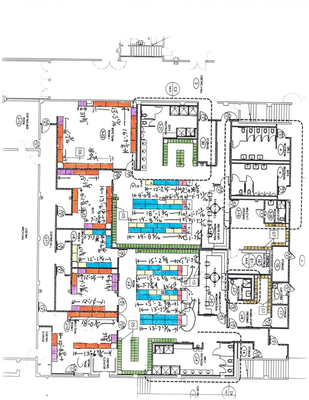
11 25 82 nd Drive, Ste. 200 Gladstone OR Sunset HS List lockers Submittal package with dimensional notes. Type A and C lockers are All-Welded. These will come in pre-welded cabinets. Refer to cut sheet showing grouping (A1, A2, and A3). The maximum width on an 18 wide door is 3 locker frames wide (53-15/16 ). Lockers need to have a maximum of ½ overhang, we normally see the bases about a ½ short on width and length to allow for some kind of overhang this is an architectural preference. - On this particular project all exposed ends receive a 1 boxed end panel, this needs to be added at ALL exposed ends. The attached drawings have this calculated into the dimensions. - We have filler panels that we typically use on all projects, they are 6 wide and are cut down in the field as needed. A 6 wide filler can be cut down to as little as 2. The attached dimensions show exactly what the lockers would take to fit, I suggest adding 4 which will allow the use of a filler if the space in the room can accommodate. Type B and D lockers are KD (Knock Down) and assembled in the field. I did not put the dimensions on the attached drawings for these areas. These are much more simple Add 1/32 growth per locker frame and each exposed end. Same rules would apply for the fillers.
12
13
14
15
16
17
18 SUPERIOR Heavy-Duty Ventilated (HDV) KD Wardrobe and Box Lockers General: Lockers shall be "Superior Heavy-Duty Ventilated (HDV) KD Wardrobe and Box Lockers" as manufactured by List Industries Inc. or approved equal. Fabricate lockers square, rigid and without warp, with metal faces flat and free from dents or distortion. Make all exposed metal edges safe to touch. Weld frame members together to form rigid, one-piece structure. Weld, bolt, or rivet other joints and connections as standard with manufacturer. Grind exposed welds flush. Do not expose bolts or rivet heads on fronts of locker doors or frames except for fastening of number plates and recessed handle. Lockers shall be GREENGUARD Children & Schools Certified SM Finishing: All locker parts to be cleaned and coated after fabrication with a seven stage zinc/iron phosphate solution to inhibit corrosion, followed by a coat of high grade custom blend powder electrostatically sprayed and baked at 350 degrees Fahrenheit for a minimum of 20 minutes to provide a tough durable finish. Color to be selected from manufacturer's standard list of colors. Interior components are to be painted choice of #729 Parchment or #725 Hallowell Gray. Two-Tone Color Combination: Shall be at no additional cost with the locker frame and trim chosen from one color and the doors may be one of any other color chosen from manufacturers standard selection. Frame: Fabricate of 16 gauge (minimum) channels, with integral continuous door stop/strike formed on both latch and hinge side vertical members. Cross frame members of 16 gauge channel shapes, including intermediate cross frame members on double and triple tier (frames with doors over 18" high) lockers shall be securely welded to the vertical framing members to ensure rigidity. Rubber bumpers shall be provided to cushion door closing. HDV Wardrobe Doors: Doors 20 high and higher shall be fabricated from single sheet prime 14 gauge with single bends at top and bottom and double bends at the sides. The channel formed by the double bend at the latch side is designed to fully conceal the lock bar. Doors are to be perforated with 5/8 x 1-1/2 diamonds. HDV Box Doors: Doors 18" high and under to be fabricated from single sheet prime 14 gauge with single bends at top, bottom and sides. Doors shall include a combination friction catch door pull. Padlock Strike Plates are optional. Doors shall be fabricated to accept a built-in combination lock or padlock. Doors with projecting spring latches shall not be acceptable. Doors are to be perforated with 7/16 x 15/16 diamonds. Stainless Steel Recessed Locker Handle: All wardrobe doors shall have recessed not less than 304 stainless steel handle shaped to receive a padlock or built-in combination lock. The recess pan shall be deep enough to have the lock be flush with the outer door face. Box doors shall be equipped with a combination friction catch door pull as stated above. 04/13/10
19 SUPERIOR Heavy-Duty Ventilated (HDV) KD Wardrobe and Box Lockers (Page 2) Latch Assembly: The latching mechanism for wardrobe doors shall be finger lift control type constructed of 14 gauge (minimum) steel with a nylon cover that has a generous finger pull. Spring activated nylon slide latches shall be completely enclosed in the lock channel allowing doors to close with the lock in the locked position. Lock bar shall be hot dip galvanized and install after paint to ensure proper paint coverage and lock bar operation. Locking devise shall be designed for use with either built-in combination locks or padlocks. Latch hooks shall be securely welded to the vertical frame channel on the strike side to engage the nylon slide latches. Three latch hooks for doors 48" and higher, two latch hooks for doors under 48" high. Door Hinges: All doors shall include a 16 gauge continuous piano hinge welded to the door and riveted to the frame. All doors to be right hand, side hinged. Body: Fabricate backs of 18 gauge (minimum) solid sheet, sides of 16 gauge (minimum) sheet steel with double flanged connections extending full height. Sides to be diamond perforated for added ventilation. Form top, bottom and intermediate tier dividers of 16 gauge (minimum) solid sheet steel with single return bends at all sides. Bolt top and bottom as well as horizontal tier dividers of wardrobe openings to front horizontal frame members at not less than one place in addition to side panels. Form hat shelves at 60 and 72 high single tier lockers of 16 gauge (minimum) sheet steel with single bends at sides and back and a double bend at front. Locks (If required): Shall be master-keyed to one system for the entire project. (See lock use chart for suggested lock application) Equipment: Furnish each locker with the following items, unless otherwise shown. Single tier lockers: Openings 60 and 72 shall include one hat shelf, one double prong ceiling hook and a minimum of two single prong hooks. Double tier lockers: Openings 30 and 36 high shall include one double prong ceiling hook and a minimum of two single prong hooks. Triple tier lockers: Openings 20 and 24 high shall include one double prong ceiling hook only. Box lockers: No hooks Two-Year Warranty: Superior KD lockers are covered against all defects in materials and workmanship excluding finish, damage resulting from deliberate destruction and vandalism under this section for a period of two years. 04/13/10
20 SUPERIOR Fully-Framed All-Welded P.E. and Team Lockers General: Lockers shall be "Superior Fully-Framed All-Welded Team & P.E. Athletic Lockers" as manufactured by List Industries Inc. or approved equal. All lockers shall be factory-assembled, of all MIG welded construction, in multiple column units to meet job conditions. Assembly of locker bodies by means of bolts, screws, or rivets will not be permitted. Welding of knockdown locker construction is not acceptable. Grind exposed welds and metal edges flush and make safe to touch. Lockers shall be GREENGUARD Children & Schools Certified SM Finishing: All locker parts to be cleaned and coated after fabrication with a seven stage zinc/iron phosphate solution to inhibit corrosion, followed by a coat of high grade custom blend powder electrostatically sprayed and baked at 350 degrees Fahrenheit for a minimum of 20 minutes to provide a tough durable finish. Color to be selected from manufacturer's standard list of colors. Two-Tone Color Combination: Shall be at no additional cost with the locker body, frame and trim chosen from one color and the doors may be one of any other color chosen from manufacturers standard selection. Frame / Vertical Side panels: Shall be of 13 gauge ½ flattened expanded metal framed by 16 gauge Hollow "T" tubular sections and channel frame members designed to enclose all four edges of the side panel with the entire assembly MIG welded to form a rigid frame for each locker. The channel frame members are welded to the front and rear vertical frame members to create and anchor bearing surface of 1-1/4 inches wide x the depth of the locker at each side panel. Integral Frame Locker base: 14 gauge formed structural channels are MIG welded to the front and rear vertical side panel frame members to allow placement of locker bottom a minimum 2-3/4" above floor level. Locker bottom shelf located less than 2 above floor level will not be acceptable. Team Wardrobe Doors: Doors 20" high and over and 15 wide and under are to be fabricated from single sheet prime 14 gauge with single bends at top and bottom and double bends at the sides. The channel formed by the double bend at the latch side is designed to fully conceal the lock bar. The latching mechanism shall be finger lift control type constructed of 14 gauge (minimum) steel with a nylon cover that has a generous finger pull. Lock bar shall be hot dip galvanized and installed after paint to ensure proper paint coverage and lock bar operation. Spring activated nylon slide latches shall be completely enclosed in the lock channel allowing doors to close with the lock in the locked position. Locking devise shall be designed for use with either built-in combination locks or padlocks. Latch hooks shall be 11 gauge (minimum) with riveted bumpers and shall be MIG welded to vertical frame member. Provide three latch hooks for doors 48" and over and two for doors under 48". Doors to be perforated with 5/8 x 1-1/2 diamonds. 06/13/11
21 SUPERIOR Fully-Framed All-Welded P.E. and Team Lockers (Page 2) P.E. Gym Doors 12 High And Under: Doors 12" high and under to be top hinged and be fabricated from single sheet prime 14 gauge with single bend at top and sides with a double bend at latch point (bottom). A spring loaded galvanized latch assembly shall be securely welded to the inside of the door. The latch shall be a minimum of 11 gauge, be equipped with a stainless steel spring and shall automatically engage when door is closed. Rubber bumpers shall be riveted to return bends on doors. Locking devise shall be designed for use with both a padlock and built-in lock. Padlock Strike Plates are optional. Doors to be perforated with 7/16 x 15/16 diamonds. P.E. Gym Doors 15 And 18 High: Doors 15 and 18" high to be side hinged and be fabricated from single sheet prime 14 gauge with single bend at top and bottom and double bends at hinge and latch sides. A spring loaded galvanized latch assembly shall be securely welded to the inside of the door. The latch shall be a minimum of 11 gauge, be equipped with a stainless steel spring and shall automatically engage an 11 gauge full height continuous door strike when the door is closed. The door strike is to be MIG welded to the frame. Rubber bumpers shall be riveted to return bends on doors. Locking devise shall be designed for use with both a padlock and built-in lock. Padlock Strike Plates are optional. Doors to be perforated with 7/16 x 15/16 diamonds. Seamless Drawn Locker Handle: All wardrobe doors 20 high and over shall have a seamless drawn not less than 304 stainless steel recessed handle shaped to receive a padlock or built-in combination lock. The recessed handle shall be deep enough to have the lock be completely flush with the outer door face. Door Hinges: Hinges for wardrobe and side hinged gym doors shall not be less than 3-1/2" long 13 gauge seven knuckle pin type, securely riveted to frame and welded to the door. Doors are to be secured to frame with a minimum of two tamper resistant rivets per hinge. Provide 3 hinges for doors 48" and higher and 2 for doors shorter than 48". All doors shall be right hand side hinged except top hinged gym doors as noted above. Top hinged gym doors shall be hinged using a 3/16" diameter continuous hinge rod completely recessed into the door with a concealed fastener. Flat Tops: Shall be formed of one piece of 16 gauge cold rolled sheet steel and shall be an integral part MIG welded to each vertical side panel frame member and be continuous to cover the full width of a multiple framed locker unit. Hat Shelves, Intermediate Shelves and Bottoms: Shall be 16 gauge galvanneal sheet steel, have double bends at front and shall engage slots in the Hollow "T" vertical frame members at all four corners and be securely welded to the frame and side. Locker bottom shelf located less than 2 above floor level will not be acceptable. Backs: Shall be 18 gauge cold rolled sheet steel, be continuous to cover a multiple framed unit and be welded to each vertical side panel frame member. 06/13/11
22 SUPERIOR Fully-Framed All-Welded P.E. and Team Lockers (Page 3) Locks (If required): Shall be master keyed to one system for the entire project. (See lock use chart for suggested lock application). Equipment: Furnish each locker with the following items, unless otherwise shown. Single tier lockers: Openings 60 and 72 shall include one galvanneal hat shelf, one double prong ceiling hook and a minimum of two single prong hooks. Double and triple tier lockers: Openings 20 thru 36 high shall include one double prong ceiling hook and a minimum of two single prong hooks. Box lockers: No hooks Lifetime Warranty: Superior Fully-Framed All-Welded Lockers are covered against all defects in materials and workmanship excluding finish, damage resulting from deliberate destruction and vandalism under this section for the lifetime of the facility. 06/13/11
23
24
25
26
27 Submittal Review TO: Pavilion Construction DATE: JOB NO.: 1484P 4700 SW Macadam Ave Suite 200 ATTENTION: Riley Tobin Portland, OR RE: BSD Sunset High School Concession Stand/Interior Renovations Package 1 Submittal: Metal Lockers Informational Submittal Approved Approved As Noted Revise as Noted/Resubmit Rejected/Resubmit As Specified No Action Required Submittal Not Requested/Returned Without Review Approval is for conformance with information given and the design concept expressed in the Contract Documents. Contractor is responsible for quantities and dimensions to be confirmed and correlated; for fabrication process; for means methods, techniques, sequences and procedures of construction; for coordination of the Work; and for all safety aspects of performing the Work. Approval does not modify the Contract Documents and approval of a specific item does not indicate approval of an assembly of which the item is a component. Specification Section Title Notation A Product Data Reviewed in Separate Submittal B Shop Drawings Reviewed in Separate Submittal C Samples For Each Color Selected Reviewed in Separate Submittal D Samples For Initial Selection Reviewed in Separate Submittal E Samples For Verification Reviewed in Separate Submittal F Product Schedule Reviewed in Separate Submittal A Qualification Data Approved B Sample Warranty Approved 1001 SW 5 th Ave. // Suite 1100 // Portland // OR // P: //
28 Sunset High School NW Cornell Rd. Portland, OR To: Attn: BLRB ARCHITECTS, P.S. RICHARD HIGGINS 1001 SW 5TH AVE., SUITE 1100 PORTLAND, OR Date: Contact Phone: Contact 06/30/ CC d: SUBMITTAL TRANSMITTAL FOR APPROVAL Submittal #: 42.1 Rev.#: 0 In Accordance with Specification Section #: This is a submittal for Metal Lockers items per the table below as reviewed and noted by Pavilion Construction NW, LLC, and provided by. Please provide a response to this submittal by 07/02/2015. Pavilion Status: Sent/Submitted Notes: Submitted By: Address: Riley Tobin rtobin@pavilionconstruction.com Phone: Fax: (503) (503) SUBMITTAL RESPONSE Architect s Response Proceed Proceed, as noted Revise and Resubmit Material Return without Review Schedule Tracking Date Date Date Date Received from Sub/Sup Requested to be returned Returned from Architect Returned to Sup/Sup 06/30/ /02/2015 Comments: PAVILION CONSTR JCTION LLC o APPROVEDAS SUBMITTEO o OISAPPROVEO, PlIASE SUBMIT COPlES ory: _APPRDVEOAS NOTEO o 06/30/15 DATED: _ F()R THE RECORD _ 06/23/15 Riley Tobin This submittal has been reviewed for general "onformil."'.ce with ttle contract documents. Tn's review does not reuevs the supplier of responsibility for erro~, omissions or any dtviition tram the requirements of the ",.....r?c! :!vr:umems. Mike Harmel Pavilion Construction NW, LLC 4700 SW Macadam Ave. Portland, OR Phone: (503) Fax: (503) Page 1 of 1
29 Sunset High School - Title IX and Upgrades Beaverton School District No. 48 BLRB Project No.: 14.84P Permit Set May 15, 2015 SECTION METAL LOCKERS PART 1 - GENERAL 1.1 RELATED DOCUMENTS A. Drawings and general provisions of the Contract, including General and Supplementary Conditions and Division 01 Specification Sections, apply to this Section. 1.2 SUMMARY A. Section Includes: 1. Knocked-down athletic lockers. 2. Welded athletic lockers. 1.3 PREINSTALLATION MEETINGS A. Preinstallation Conference: Conduct conference at Project site. 1.4 ACTION SUBMITTALS A. Product Data: For each type of metal locker. 1. Include construction details, material descriptions, dimensions of individual components and profiles, and finishes for each type of metal locker. B. Shop Drawings: For metal lockers. 1. Include plans, elevations, sections, details, and attachments to other work. 2. Show locker trim and accessories. 3. Include locker identification system and numbering sequence. C. Samples: For each color specified, in manufacturer's standard size. D. Samples for Initial Selection: Manufacturer's color charts showing the full range of colors available. E. Samples for Verification: For the following products, in manufacturer's standard size: 1. Lockers and equipment. 2. Locker benches. F. Product Schedule: For lockers. 1.5 INFORMATIONAL SUBMITTALS A. Qualification Data: For Installer. B. Sample Warranty: For special warranty. BLRB Architects - Portland, Oregon METAL LOCKERS
30 Sunset High School - Title IX and Upgrades Beaverton School District No. 48 BLRB Project No.: 14.84P Permit Set May 15, CLOSEOUT SUBMITTALS A. Maintenance Data: For adjusting, repairing, and replacing locker doors and latching mechanisms to include in maintenance manuals. 1.7 MAINTENANCE MATERIAL SUBMITTALS A. Furnish extra materials that match products installed and that are packaged with protective covering for storage and identified with labels describing contents. 1. Full-size units of the following metal locker hardware items equal to 10 percent of amount installed for each type and finish installed, but no fewer than five units: 2. Locks. a. Identification plates. b. Hooks. 1.8 DELIVERY, STORAGE, AND HANDLING A. Do not deliver metal lockers until spaces to receive them are clean, dry, and ready for their installation. 1.9 FIELD CONDITIONS A. Field Measurements: Verify actual dimensions of recessed openings by field measurements before fabrication COORDINATION A. Coordinate sizes and locations of concrete bases for metal lockers. B. Coordinate sizes and locations of framing, blocking, furring, reinforcements, and other related units of work specified in other Sections to ensure that metal lockers can be supported and installed as indicated WARRANTY A. Special Warranty: Manufacturer agrees to repair or replace components of metal lockers that fail in materials or workmanship, excluding finish, within specified warranty period. 1. Failures include, but are not limited to, the following: a. Structural failures. b. Faulty operation of latches and other door hardware. 2. Damage from deliberate destruction and vandalism is excluded. 3. Warranty Period for Knocked-Down Metal Lockers: Two years from date of Substantial Completion. 4. Warranty Period for Welded Metal Lockers: Lifetime from date of Substantial Completion. BLRB Architects - Portland, Oregon METAL LOCKERS
31 Sunset High School - Title IX and Upgrades Beaverton School District No. 48 BLRB Project No.: 14.84P Permit Set May 15, 2015 PART 2 - PRODUCTS 2.1 MANUFACTURERS A. Source Limitations: Obtain metal lockers and accessories from single source from single locker manufacturer. 1. Obtain locks from single lock manufacturer. 2.2 PERFORMANCE REQUIREMENTS A. Accessibility Requirements: For lockers indicated to be accessible, comply with applicable provisions in the U.S. Architectural & Transportation Barriers Compliance Board's ADA-ABA Accessibility Guidelines and ICC A KNOCKED-DOWN ATHLETIC LOCKERS A. Basis-of-Design Product: Subject to compliance with requirements, provide Republic Storage Systems, LLC; Heavy Duty Ventilated or a comparable product by one of the following: 1. Art Metal Products. 2. Lyon Workspace Products, LLC. 3. Penco Products, Inc. B. Perforated Doors: One piece; fabricated from inch nominal-thickness steel sheet with manufacturer's standard diamond perforations; formed into channel shape with double bend at vertical edges and with right-angle single bend at horizontal edges and latch point (bottom) and right-angle single bend at remaining edges for box lockers. 1. Reinforcement: Manufacturer's standard reinforcing angles, channels, or stiffeners for doors more than 15 inches wide; welded to inner face of doors. C. Body: Assembled by riveting or bolting body components together. Fabricate from unperforated steel sheet with thicknesses as follows: 1. Tops and Bottoms: inch nominal thickness, with single bend at edges. 2. Backs: inch nominal thickness. 3. Shelves: inch nominal thickness, with double bend at front and single bend at sides and back. D. Unperforated Sides: Fabricated from inch nominal-thickness steel sheet. E. Frames: Channel formed; fabricated from inch nominal-thickness steel sheet or inch nominal-thickness steel angles; lapped and factory welded at corners; with top and bottom main frames factory welded into vertical main frames. Form continuous, integral, full-height door strikes on vertical main frames. 1. Cross Frames for Double-Tier and Triple-Tier Lockers: Channel formed and fabricated from same material as main frames; welded to vertical main frames. F. Hinges: Welded to door and attached to door frame with no fewer than two factory-installed rivets per hinge that are completely concealed and tamper resistant when door is closed; fabricated to swing 180 degrees. 1. Knuckle Hinges: Steel, full loop, five or seven knuckles, tight pin; minimum 2 inches high. Provide no fewer than three hinges for each door more than 42 inches high. BLRB Architects - Portland, Oregon METAL LOCKERS
32 Sunset High School - Title IX and Upgrades Beaverton School District No. 48 BLRB Project No.: 14.84P Permit Set May 15, 2015 G. Door Handle and Latch: Stainless-steel strike plate with integral pull; with steel padlock loop that projects through metal locker door. H. Identification Plates: Manufacturer's standard, etched, embossed, or stamped aluminum plates, with numbers and letters at least 3/8 inch high. I. Hooks: Manufacturer's standard ball-pointed type, aluminum or steel; zinc plated. J. Coat Rods: Manufacturer's standard. K. Continuous Sloping Tops: Fabricated from inch nominal-thickness steel sheet, with a pitch of approximately 20 degrees. 1. Closures: Vertical-end type. L. Filler Panels: Fabricated from inch nominal-thickness steel sheet. M. Boxed End Panels: Fabricated from inch nominal-thickness steel sheet. N. Materials: 1. Cold-Rolled Steel Sheet: ASTM A 1008/A 1008M, Commercial Steel (CS), Type B, suitable for exposed applications. O. Finish: Baked enamel or powder coat. 1. Color: As selected by Architect from manufacturer's full range. 2.4 WELDED ATHLETIC LOCKERS A. Basis-of-Design Product: Subject to compliance with requirements, provide Republic Storage Systems, LLC; All-Welded Ventilated or a comparable product by one of the following: 1. Art Metal Products. 2. Lyon Workspace Products, LLC. 3. Penco Products, Inc. B. Perforated Doors: One piece; fabricated from inch nominal-thickness steel sheet with manufacturer's standard diamond perforations; formed into channel shape with double bend at vertical edges and with right-angle single bend at horizontal edges and latch point (bottom) and right-angle single bend at remaining edges for box lockers. 1. Reinforcement: Manufacturer's standard reinforcing angles, channels, or stiffeners for doors more than 15 inches wide; welded to inner face of doors. C. Body: Assembled by welding body components together. Fabricate from unperforated steel sheet with thicknesses as follows: 1. Tops and Bottoms: inch nominal thickness, with single bend at edges. 2. Backs: inch nominal thickness. 3. Shelves: inch nominal thickness, with double bend at front and single bend at sides and back. D. Unperforated Sides: Fabricated from inch nominal-thickness steel sheet. E. Frames: Channel formed; fabricated from inch nominal-thickness steel sheet or inch nominal-thickness steel angles; lapped and factory welded at corners; with top and bottom main frames factory welded into vertical main frames. Form continuous, integral, full-height door strikes on vertical main frames. BLRB Architects - Portland, Oregon METAL LOCKERS
33 Sunset High School - Title IX and Upgrades Beaverton School District No. 48 BLRB Project No.: 14.84P Permit Set May 15, Cross Frames for Double-Tier and Triple-Tier Lockers: Channel formed and fabricated from same material as main frames; welded to vertical main frames. F. Hinges: Welded to door and attached to door frame with no fewer than two factory-installed rivets per hinge that are completely concealed and tamper resistant when door is closed; fabricated to swing 180 degrees. 1. Knuckle Hinges: Steel, full loop, five or seven knuckles, tight pin; minimum 2 inches high. Provide no fewer than three hinges for each door more than 42 inches high. G. Door Handle and Latch: Stainless-steel strike plate with integral pull; with steel padlock loop that projects through metal locker door. H. Identification Plates: Manufacturer's standard, etched, embossed, or stamped aluminum plates, with numbers and letters at least 3/8 inch high. I. Hooks: Manufacturer's standard ball-pointed type, aluminum or steel; zinc plated. J. Coat Rods: Manufacturer's standard. K. Continuous Sloping Tops: Fabricated from inch nominal-thickness steel sheet, with a pitch of approximately 20 degrees. 1. Closures: Vertical-end type. L. Filler Panels: Fabricated from inch nominal-thickness steel sheet. M. Boxed End Panels: Fabricated from inch nominal-thickness steel sheet. N. Materials: 1. Cold-Rolled Steel Sheet: ASTM A 1008/A 1008M, Commercial Steel (CS), Type B, suitable for exposed applications. O. Finish: Baked enamel or powder coat. 1. Color: As selected by Architect from manufacturer's full range. 2.5 FABRICATION A. Fabricate metal lockers square, rigid, without warp, and with metal faces flat and free of dents or distortion. Make exposed metal edges safe to touch and free of sharp edges and burrs. 1. Form body panels, doors, shelves, and accessories from one-piece steel sheet unless otherwise indicated. 2. Provide fasteners, filler plates, supports, clips, and closures as required for complete installation. B. Fabricate each metal locker with an individual door and frame; individual top, bottom, and back; and common intermediate uprights separating compartments. Factory weld frame members of each metal locker together to form a rigid, one-piece assembly. C. Equipment: Provide each locker with an identification plate and the following equipment: 1. Single-Tier Units: Shelf, one double-prong ceiling hook, and two single-prong wall hooks. 2. Double-Tier Units: One double-prong ceiling hook and two single-prong wall hooks. 3. Triple-Tier Units: One double-prong ceiling hook. 4. Coat Rods: For each compartment of each locker. BLRB Architects - Portland, Oregon METAL LOCKERS
34 Sunset High School - Title IX and Upgrades Beaverton School District No. 48 BLRB Project No.: 14.84P Permit Set May 15, 2015 D. Knocked-Down Construction: Fabricate metal lockers using nuts, bolts, screws, or rivets for nominal assembly at Project site. E. Welded Construction: Factory preassemble metal lockers by welding all joints, seams, and connections; with no bolts, nuts, screws, or rivets used in assembly of main locker groups. Factory weld main locker groups into one-piece structures. Grind exposed welds flush. F. Accessible Lockers: Fabricate as follows: 1. Locate bottom shelf no lower than 15 inches above the floor. 2. Where hooks, coat rods, or additional shelves are provided, locate no higher than 48 inches above the floor. G. Continuous Base: Formed into channel or zee profile for stiffness, and fabricated in lengths as long as practical to enclose base and base ends of metal lockers; finished to match lockers. H. Continuous Sloping Tops: Fabricated in lengths as long as practical, without visible fasteners at splice locations; finished to match lockers. 1. Sloping-top corner fillers, mitered. I. Individual Sloping Tops: Fabricated in width to fit one locker frame in lieu of flat locker tops; with integral back; finished to match lockers. Provide wedge-shaped divider panels between lockers. J. Recess Trim: Fabricated with minimum 2-1/2-inch face width and in lengths as long as practical; finished to match lockers. K. Filler Panels: Fabricated in an unequal leg angle shape; finished to match lockers. Provide slip-joint filler angle formed to receive filler panel. L. Boxed End Panels: Fabricated with 1-inch-wide edge dimension, and designed for concealing fasteners and holes at exposed ends of nonrecessed metal lockers; finished to match lockers. 1. Provide one-piece panels for double-row (back-to-back) locker ends. M. Finished End Panels: Designed for concealing unused penetrations and fasteners, except for perimeter fasteners, at exposed ends of nonrecessed metal lockers; finished to match lockers. 1. Provide one-piece panels for double-row (back-to-back) locker ends. N. Center Dividers: Full-depth, vertical partitions between bottom and shelf; finished to match lockers. 2.6 ACCESSORIES A. Fasteners: Zinc- or nickel-plated steel, slotless-type, exposed bolt heads; with self-locking nuts or lock washers for nuts on moving parts. B. Anchors: Material, type, and size required for secure anchorage to each substrate. 1. Provide nonferrous-metal or hot-dip galvanized anchors and inserts on inside face of exterior walls for corrosion resistance. 2. Provide toothed-steel or lead expansion sleeves for drilled-in-place anchors. BLRB Architects - Portland, Oregon METAL LOCKERS
35 Sunset High School - Title IX and Upgrades Beaverton School District No. 48 BLRB Project No.: 14.84P Permit Set May 15, 2015 PART 3 - EXECUTION 3.1 EXAMINATION A. Examine walls, floors, and support bases, with Installer present, for compliance with requirements for installation tolerances and other conditions affecting performance of the Work. B. Prepare written report, endorsed by Installer, listing conditions detrimental to performance of the Work. C. Proceed with installation only after unsatisfactory conditions have been corrected. 3.2 INSTALLATION A. General: Install lockers level, plumb, and true; shim as required, using concealed shims. 1. Anchor locker runs at ends and at intervals recommended by manufacturer, but not more than 36 inches o.c. Using concealed fasteners, install anchors through backup reinforcing plates, channels, or blocking as required to prevent metal distortion. 2. Anchor single rows of metal lockers to walls near top of lockers and to floor. 3. Anchor back-to-back metal lockers to floor. B. Knocked-Down Lockers: Assemble with standard fasteners, with no exposed fasteners on door faces or face frames. C. Welded Lockers: Connect groups together with standard fasteners, with no exposed fasteners on face frames. D. Equipment: 1. Attach hooks with at least two fasteners. 2. Attach door locks on doors using security-type fasteners. 3. Identification Plates: Identify metal lockers with identification indicated on Drawings. a. Attach plates to each locker door, near top, centered, with at least two aluminum rivets. b. Attach plates to upper shelf of each open-front metal locker, centered, with a least two aluminum rivets. E. Trim: Fit exposed connections of trim, fillers, and closures accurately together to form tight, hairline joints, with concealed fasteners and splice plates. 1. Attach recess trim to recessed metal lockers with concealed clips. 2. Attach filler panels with concealed fasteners. Locate filler panels where indicated on Drawings. 3. Attach sloping-top units to metal lockers, with closures at exposed ends. 4. Attach boxed end panels using concealed fasteners to conceal exposed ends of nonrecessed metal lockers. 5. Attach finished end panels using fasteners only at perimeter to conceal exposed ends of nonrecessed metal lockers. F. Fixed Locker Benches: Provide no fewer than two pedestals for each bench, uniformly spaced not more than 72 inches apart. Securely fasten tops of pedestals to undersides of bench tops, and anchor bases to floor. G. Freestanding Locker Benches: Place benches in locations indicated on Drawings. BLRB Architects - Portland, Oregon METAL LOCKERS
36 Sunset High School - Title IX and Upgrades Beaverton School District No. 48 BLRB Project No.: 14.84P Permit Set May 15, ADJUSTING A. Clean, lubricate, and adjust hardware. Adjust doors and latches to operate easily without binding. 3.4 PROTECTION A. Protect metal lockers from damage, abuse, dust, dirt, stain, or paint. Do not permit use during construction. B. Touch up marred finishes, or replace metal lockers that cannot be restored to factory-finished appearance. Use only materials and procedures recommended or furnished by locker manufacturer. END OF SECTION BLRB Architects - Portland, Oregon METAL LOCKERS
37
38
39
40
41

42 SUPERIOR FULLY-FRAMED ALL WELDED LOCKERS LIFETIME WARRANTY To: Sample Project: Sample LIST INDUSTRIES, INC. JOB: Sample Substantial Completion Date: Sample Superior Fully-Framed Lockers carry a lifetime warranty against defect in materials and workmanship. Rust resulting from excessive use of cleaning agents, exposed to water from open doors and windows or roof leaks, improper ventilation causing high humidity, and chlorine saturated bathing suits will not be covered by this warranty. The warranty only applies to components manufactured by List Industries Inc. and excludes those items such as locks, wood bench-tops, cast iron pedestals, etc. Damage resulting from deliberate destruction, vandalism, shipping or faulty installation is not covered by this warranty. Any repairs, adjustments or replacements to be made under this warranty shall be performed only upon authorization in writing by List Industries Inc. 401 Jim Moran Blvd, P.O. Box 9601, Deerfield Beach, FL tel fax
B. Shop Drawings: For metal lockers. Include plans, elevations, sections, details, and attachments to other work.
 SECTION 10 5113 - METAL LOCKERS PART 1 - GENERAL 1.1 RELATED DOCUMENTS A. Drawings and general provisions of the Contract, including General and Supplementary Conditions and Division 1 Specification Sections,
UNIVERSITY SERVICES ANNEX James Madison University Harrisonburg, Virginia State Project Code: Architect s Project Number:
 SECTION 105113 - METAL LOCKERS PART 1 - GENERAL 1.1 RELATED DOCUMENTS A. Provisions of the Contract and of the Contract Documents apply to this Section. 1.2 SUBMITTALS A. Product Data: For each type of
1. Standard two tier metal lockers and metal base.
 SECTION 105113 - METAL LOCKERS PART 1 - GENERAL 1.1 RELATED DOCUMENTS A. Drawings and general provisions of the Contract, including General and Supplementary Conditions and Division 01 Specification Sections,
SECTION METAL ATHLETIC LOCKERS
 SECTION 10 51 13 - METAL ATHLETIC LOCKERS PART 1 GENERAL 1.1 SECTION INCLUDES A. DESCRIPTION: Furnish and install factory-assembled Heavy-Duty MIG-Welded Metal Lockers, complete, as shown and specified
SECTION METAL ATHLETIC LOCKERS
 SECTION 10 51 13 - METAL ATHLETIC LOCKERS PART 1 GENERAL 1.1 SECTION INCLUDES A. DESCRIPTION: Furnish and install factory-assembled Heavy-Duty MIG-Welded Metal Lockers, complete, as shown and specified
Hobby Parking Office HOU/ Proj./ No. 738 Houston, Texas 100% Bid and Construction Documents- Addendum #3, January 27, 2017
 SECTION 105113 - METAL LOCKERS PART 1 - GENERAL 1.1 SUMMARY A. Section Includes: 1. Knocked-down corridor lockers (double tier) 1.2 ACTION SUBMITTALS A. Product data. B. Shop Drawings: Include plans, elevations,
SECTION METAL STUDENT LOCKERS
 SECTION 10 51 13 - METAL STUDENT LOCKERS PART 1 GENERAL 1.1 SECTION INCLUDES 1. DESCRIPTION: Furnish and install Heavy-Duty Ventilated (HDV) ELITE Metal Lockers, complete, as shown and specified per contract
PASSAIC COUNTY TECHNICAL INSTITUTE CCA 1422 NEW S.T.E.M. BUILDING 2017
 SECTION 10505 - METAL STUDENT LOCKERS PART 1 - GENERAL 1.01 SCOPE OF WORK A. Drawings and general provisions of the Contract, including General and Supplementary Conditions and Division 1 Specification
DIVISION 10 SPECIALTIES SECTION METAL LOCKERS
 DIVISION 10 SPECIALTIES SECTION 10 51 13 PART 1 - GENERAL 1.1 RELATED DOCUMENTS A. Drawings and general provisions of the Contract, including General and Supplementary Conditions and Division 01 Specification
SECTION METAL LOCKERS
 PART 1 GENERAL 1.1 DESCRIPTION SECTION 10 51 13 1. Use this section only for NCA projects. 2. Delete between // // if not applicable to project. Also delete any other items or paragraphs not applicable
SECTION METAL EQUIPMENT LOCKERS
 SECTION 10 51 13 - METAL EQUIPMENT LOCKERS PART 1 GENERAL 1.1 SECTION INCLUDES A. DESCRIPTION: Furnish and install factory-assembled Heavy-Duty MIG-Welded Metal Lockers, complete, as shown and specified
HALLOWELL FORT KNOX Modular Utility Storage and Workbench System Specifications
 General: All modular components shall be "FORT KNOX Modular Utility Storage and Workbench System" components as manufactured by Hallowell or approved equal. All workbench pedestals, cabinets and lockers
WEC Manufacturing Phone: (901) Website: Itswec.com
 Website: Itswec.com") All Welded Plus Series Part 1: General 1.1 Construction Requirements: All lockers shall be powder coated steel as design and manufactured by WEC, Memphis, Tennessee. WEC will furnish all labor and materials
All Welded Plus Series Part 1: General 1.1 Construction Requirements: All lockers shall be powder coated steel as design and manufactured by WEC, Memphis, Tennessee. WEC will furnish all labor and materials
Submittal Review A
 Submittal Review TO: Pavilion Construction DATE: 07.20.2015 JOB NO.: 1484P 4700 SW Macadam Ave Suite 200 ATTENTION: Riley Tobin Portland, OR 97239 RE: BSD Sunset High School Concession Stand/Interior Renovations
SECTION PERSONNEL DUTY LOCKERS. 1. FPPL Series Police Personnel Duty Lockers, including the following:
 SECTION 10501 PERSONNEL DUTY LOCKERS PART 1 GENERAL 1.01 RELATED DOCUMENTS A. Drawings and general provisions of the Contract, including General and Supplementary Conditions and Division 1 specifications
a. Include statement indicating location of manufacturer and distance to Project for each regionally manufactured material.
 SECTION 101423- PANEL SIGNAGE PART 1 -GENERAL 1.1 SUMMARY Section Includes: 1. Room-identification signs. 1.2 ACTION SUBMITTALS Product Data: For each type of product. LEED Submittals: 1. 'Product Certificates
WEC Manufacturing Phone: (901) Website: Itswec.com
 Website: Itswec.com") Part1:General Fire&RescueLockers:CompetitiveSeries 1.1ConstructionRequirements:Alllockersshallbepowder coatedsteelasdesignand manufactured by WEC, Memphis, Tennessee. WEC will furnish all labor and materials
Part1:General Fire&RescueLockers:CompetitiveSeries 1.1ConstructionRequirements:Alllockersshallbepowder coatedsteelasdesignand manufactured by WEC, Memphis, Tennessee. WEC will furnish all labor and materials
SECTION PLASTIC LOCKERS. A. ADAAG - Americans with Disabilities Act, Accessibility Guidelines.
 SECTION 10 51 26 PLASTIC LOCKERS PART 1 GENERAL 1.01 SECTION INCLUDES A. Fully Assembled High Density Polyethylene Lockers B. High Density Polyethylene Benches 1.02 REFERENCES A. ADAAG - Americans with
1. Seismic Loads: Reference structural drawings.
 SECTION 102213 ~WIRE MESH PARTITIONS PART 1 - GENERAL 1.1 RELATED DOCUMENTS A. Drawings and general prov1s1ons of the Contract, including General and Supplementary Conditions and Division 01 Specification
1. Bullet resistant hollow metal door and frame assemblies tested in accordance with UL 7 52 and in compliance with the following:
 Various Locations PROJECT#: R1401-01 SECTION 083400 -BULLET RESISTANT DOOR AND FRAMES PART 1-GENERAL 1.1 RELATED DOCUMENTS Drawings and general provisions of the Contract, including General and Supplementary
SECTION / HEAVY DUTY WIRE MESH WINDOW GUARDS
 SECTION 10605 / 10 22 13 HEAVY DUTY WIRE MESH WINDOW GUARDS ** NOTE TO SPECIFIER ** heavy duty woven wire mesh partitions, wire mesh infill panels, window guards, and area guarding.. This section is based
BID # ELLIS MIDDLE LOCKERS
 BID # 20140729 ELLIS MIDDLE LOCKERS The Sumner County Board of Education, herein known as School System, is soliciting bids for the purchase and installation of new lockers. The vendor must include cost
Solid HDPE Plastic Lockers ROYAL LOCKERS
 Solid HDPE Plastic Lockers ROYAL LOCKERS STANDARD CONFIGURATIONS AND OPTIONS Never needs painting, 10 standard colors Impervious to moisture and cleaners Full Plastic Hinge and Strike Vandal resistant
1. Include plans, elevations, sections, details, and attachments to other work.
 SECTION 102213- PART 1 -GENERAL 1.1 RELATED DOCUMENTS A. Drawings and general provisions of the Contract, including General and Supplementary Conditions and Division 01 Specification Sections, apply to
SECTION Summit Phenolic Lockers (Solid Phenolic Lockers)
") SECTION 10 51 00 Summit Phenolic Lockers (Solid Phenolic Lockers) Part 1-General 1.01 Summary A. Section includes: solid phenolic lockers solid phenolic benches 1.02 Submittals A. Submittals: Comply with
SECTION 10 51 00 Summit Phenolic Lockers (Solid Phenolic Lockers) Part 1-General 1.01 Summary A. Section includes: solid phenolic lockers solid phenolic benches 1.02 Submittals A. Submittals: Comply with
Architectural Specifications, Section Phenolic Lockers
 Architectural Specifications, Section 10500 Phenolic Lockers Hollman, Inc., 1825 W. Walnut Hill Lane, Irving, TX 75038, (972) 815-4000, www.hollman.com 1.0 GENERAL 1.1 SECTION INCLUDES A. Phenolic Lockers.
SECTION ACCESS DOORS AND FRAMES
 SECTION 08310 ACCESS DOORS AND FRAMES PART 1 - GENERAL 1.1 SUMMARY A. Section includes: 1. [Fire rated] [and] [Non-fire rated] wall access panels. 2. [Fire rated] [and] [Non-fire rated] ceiling access
SECTION CHAIN LINK FENCES AND GATES (PARK)
") SECTION 02821 CHAIN LINK FENCES AND GATES (PARK) PART I GENERAL 1.1 SECTION INCLUDES A. Installation of chain link fences, and gate units provided by single source including erection accessories, fittings,
SECTION 02821 CHAIN LINK FENCES AND GATES (PARK) PART I GENERAL 1.1 SECTION INCLUDES A. Installation of chain link fences, and gate units provided by single source including erection accessories, fittings,
1. Include construction details, materials, individual components and profiles, and finishes.
 SECTION 08 31 13 - ACCESS DOORS AND FRAMES PART 1 - GENERAL 1.1 RELATED DOCUMENTS A. Drawings,and general provisions of the Contract, including General and Supplementary Conditions and Division 01 Specification
1. Supply, delivery, engineering and installation of new storage equipment.
 SECTION 10 51 13 - METAL LOCKERS * ALL FIELDS IN [ ] MUST BE EDITED PART 1 - GENERAL 1.1. RELATED DOCUMENTS A. Drawings and general provisions of the Contract, including General and Supplementary Conditions
SECTION MISCELLANEOUS METALS
 PART 1 GENERAL 1.1 WORK OF THIS SECTION A. Contractor shall provide all labor, materials, equipment and incidentals as shown, specified and required to furnish and install all miscellaneous metal fabrications
C. Samples: For each door face material, at least 3 by 5 inches (75 by 125 mm) in size, in specified finish.
 in size, in specified finish.") SECTION 083113 - ACCESS DOORS AND FRAMES PART 1 - GENERAL 1.1 RELATED DOCUMENTS A. Drawings and general provisions of the Contract, including General and Supplementary Conditions and Division 01 Specification
SECTION 083113 - ACCESS DOORS AND FRAMES PART 1 - GENERAL 1.1 RELATED DOCUMENTS A. Drawings and general provisions of the Contract, including General and Supplementary Conditions and Division 01 Specification
SECTION DETENTION WINDOW SCREENS. 1. Detention screens for interior and exterior installations at exterior windows in existing buildings.
 SECTION 08 56 66 DETENTION WINDOW SCREENS SPEC WRITER NOTE: Delete text between // // not applicable to project. Edit remaining text to suit project. PART 1 - GENERAL 1.1 SUMMARY A. Section Includes: SPEC
SECTION STEEL DOORS AND FRAMES PART 1 - GENERAL 1.1 RELATED DOCUMENTS
 SECTION 08110 - STEEL DOORS AND FRAMES PART 1 - GENERAL 1.1 RELATED DOCUMENTS A. Drawings and general provisions of Contract, including General, Supplementary, and Special Conditions and Division 1 Specification
SECTION [ ] COILING COUNTER DOORS. Display hidden notes to specifier. (Don't know how? Click Here)
![SECTION [ ] COILING COUNTER DOORS. Display hidden notes to specifier. (Don't know how? Click Here)](/thumbs/77/75601156.jpg "SECTION [ ] COILING COUNTER DOORS. Display hidden notes to specifier. (Don't know how? Click Here)") SECTION 08332 [08 33 13] COILING COUNTER DOORS Display hidden notes to specifier. (Don't know how? Click Here) PART 1 GENERAL 1.1 SECTION INCLUDES A. Coiling Metal Counter Doors. B. Coiling Metal Counter
SECTION 08332 [08 33 13] COILING COUNTER DOORS Display hidden notes to specifier. (Don't know how? Click Here) PART 1 GENERAL 1.1 SECTION INCLUDES A. Coiling Metal Counter Doors. B. Coiling Metal Counter
Nortrax Section David Manchester Road, Ottawa NON-STRUCTURAL METAL FRAMING 16 May 2014 Page 1
 16 May 2014 Page 1 PART 1 GENERAL 1.1 DESCRIPTION This section specifies steel studs wall systems, shaft wall systems, ceiling or soffit suspended or furred framing, wall furring, fasteners, and accessories
SCI-FAB Product Specifications. Casework Section 1. Part 1 General
 SCI-FAB Product Specifications Casework Section 1 Part 1 General 1.1 SCOPE OF WORK Includes all factory fabricated stainless steel casework as required by the project drawings. 1.2 TYPICAL INCLUSIONS A.
Architectural Wall Products Guide Specifications
 Western States Metal Roofing 901 W. Watkins St. Phoenix, AZ 85007 PH: 602-495-0048 FX: 602-261-7726 Architectural Wall Products Guide Specifications FORMED METAL WALL PANELS This Guide Specification is
Hamilton International Air Cargo Logistics Facility Section November 2014 Page 1 of 4
 Hamilton International Air Cargo Logistics Facility Section 10 21 14 METAL TOILET COMPARTMENTS Page 1 of 4 Part 1 General 1.1 SECTION INCLUDES.1 Metal toilet compartments, floor mounted. 1.2 RELATED SECTIONS.1
SECTION PHENOLIC LOCKERS AND BENCHES. B. Section Gypsum Board Area Separation Wall Assemblies.
 SECTION 10 51 29 PHENOLIC LOCKERS AND BENCHES PART 1 GENERAL 1.1 SECTION INCLUDES A. Phenolic lockers, hardware and accessories. B. Phenolic pedestal benches. C. Phenolic cubbies. 1.2 RELATED SECTIONS
NORTHWESTERN UNIVERSITY PROJECT NAME JOB # ISSUED: 03/29/2017
 SECTION 10 2113.19 - PLASTIC TOILET COMPARTMENTS PART 1 - GENERAL 1.1 RELATED DOCUMENTS A. Drawings and general provisions of the Contract, including General and Supplementary Conditions and Division 01
Architectural Roof and Wall Products Guide Specifications
 Architectural Roof and Wall Products Guide Specifications Western States Metal Roofing 901 W. Watkins St. Phoenix, AZ 85007 PH: 602-495-0048 FX: 602-261-7726 FORMED METAL WALL PANELS This Guide Specification
B. Polyethylene samples shall be submitted for Owner approval of color and quality.
 Glass Rail ENGINEERED DASHERBOARD SPECIFICATIONS PART 1 - GENERAL 1.01 PROJECT SCOPE A. Contractor shall furnish and install one complete set of steel framed dasherboards as indicated on the drawings and
Architectural Roof and Wall Products Guide Specifications
 Architectural Roof and Wall Products Guide Specifications 901 W. Watkins St. Phoenix, AZ 85007 PH: 602-495-0048 FX: 602-261-7726 FORMED METAL ROOF AND WALL PANELS This Guide Specification is to be used
220 E. General Robinson St. Pittsburgh, PA fax
 B BAR-CO ACCESS DOORS... 4 D DOOR Bar-Co Access... 4 Republic & Frames... 2 DORMA Architectural Hardware... 6 G GENERAL PARTITIONS... 7 L LOCKER... 5 M MOHAWK DOORS... 3 P PIPE RAILING... 8 R RAILING...
SECTION ACCORDION FOLDING PARTITIONS
 PART 1 - GENERAL 1.1 DESCRIPTION: SECTION 10 22 26.13 ACCORDION FOLDING PARTITIONS SPEC WRITER NOTE: Delete between // // if not applicable to project. Also delete any other item or paragraph not applicable
SECTION MEDICATION CABINET. 1.1 SUMMARY A. Section Includes: 1. Medication cabinets with self-contained refrigerator and fixtures.
 SECTION 12 35 70.21 MEDICATION CABINET SPEC WRITER NOTE: Delete text between // // not applicable to project. Edit remaining text to suit project. PART 1 - GENERAL 1.1 SUMMARY A. Section Includes: 1. Medication
SECTION HANDRAILS AND RAILINGS. A. Section Cast-In-Place Concrete; coordination with substrate.
 SECTION 05520 HANDRAILS AND RAILINGS PART 1 GENERAL 1.1 SECTION INCLUDES A. Welded stainless steel railing systems. 1.2 RELATED SECTIONS A. Section 03300 - Cast-In-Place Concrete; coordination with substrate.
SECTION HOLLOW METALWORK. A. PART A and DIVISION 1 of PART B are hereby made a part of this SECTION.
 SECTION 081113 PART 1 GENERAL 1.01 GENERAL REQUIREMENTS A. PART A and DIVISION 1 of PART B are hereby made a part of this SECTION. B. Examine all conditions as they exist at the project prior to submitting
10331 Date Street Murrieta, CA SECTION HYBRID LAMINATE LOCKERS W/ PHENOLIC DOORS
 09/20/2017 10331 Date Street Murrieta, CA 92562 info@foremanproducts.com 951-677-1955 SECTION 10 5130 HYBRID LAMINATE LOCKERS W/ PHENOLIC DOORS PART 1 GENERAL Specifier Notes: This product specification
SECTION NON-STRUCTURAL METAL FRAMING
 SECTION 09 22 16 PART 1 - GENERAL 1.1 DESCRIPTION A. This section specifies steel studs wall systems, shaft wall systems, ceiling or soffit suspended or furred framing, wall furring, fasteners, and accessories
Aluminum Perforated Rolling Door
 Model ALUMA-VISION Perforated Curved or Flat Slats Rolling Service Door NOTE: For specifications, architects must choose from a variety of options. The standard choice will be shown first in plain text
Architectural Roof Products Guide Specifications
 Western States Metal Roofing 901 W. Watkins St. Phoenix, AZ 85007 PH: 602-495-0048 FX: 602-261-7726 Architectural Roof Products Guide Specifications FORMED METAL ROOF AND WALL PANELS This Guide Specification
PH6000. Key Features
 Phenolic Locker Series PH6000 Key Features ½ inch doors and end panels Durable, backed by a 20 year warranty. Ideal choice for wet-use areas including pools and recreation centers Graffiti resistant, permanent
SECTION TOILET PARTITIONS. A. Section Structural Steel: Supports for ceiling hung compartments.
 SECTION 10155 TOILET PARTITIONS PART 1 GENERAL 1.1 SECTION INCLUDES A. Stainless steel toilet compartments. 1.2 RELATED SECTIONS A. Section 05120 - Structural Steel: Supports for ceiling hung compartments.
SECTION ENTRANCE FLOOR GRILLES STAINLESS STEEL GRATING
 7160 Krick Rd., Walton Hills, OH 44146 800-321-3827 - Tel 440-439-8650 - Fax 440-439-6889 SECTION 12 48 16 ENTRANCE FLOOR GRILLES STAINLESS STEEL GRATING PART 1. GENERAL 1.01 SUMMARY: This section includes
SECTION ENTRANCE FLOOR GRILLES STAINLESS STEEL GRATING
 7160 Krick Rd., Walton Hills, OH 44146 800-321-3827 - Tel 440-439-8650 - Fax 440-439-6889 SECTION 12 48 16 ENTRANCE FLOOR GRILLES STAINLESS STEEL GRATING PART 1. GENERAL 1.01 SUMMARY: This section includes
1. Base plates, setting plates and anchor rods for columns. 8. Lintels if connected to structural steel columns.
 PAGE 051200-1 SECTION 051200 PART 1 - GENERAL 1.1 RELATED DOCUMENTS A. Drawings and general provisions of the Contract, including General and Supplementary Conditions and Division 01 Specification sections,
Architectural Roof Products Guide Specifications
 Western States Metal Roofing 901 W. Watkins St. Phoenix, AZ 85007 PH: 602-495-0048 FX: 602-261-7726 Architectural Roof Products Guide Specifications FORMED METAL ROOF AND WALL PANELS This Guide Specification
SECTION AWNINGS
 SECTION 10 73 13 AWNINGS PART 1 - GENERAL 1.1 SUMMARY A. This Section includes the following: 1. Fixed metal awnings. 1.2 DEFINITIONS A. Awning: An architectural projection that provides weather protection,
A. Access doors and frames are part of an access door and frame allowance.
 SECTION 08 31 13 ACCESS DOORS AND FRAMES PART 1 GENERAL 1.1 RELATED DOCUMENTS A. Drawings and general provisions of the Contract, including General and Supplementary Conditions and Division 01 Specification
SECTION ALUMINUM HANDRAIL SYSTEMS
 SECTION 05520 ALUMINUM HANDRAIL SYSTEMS PART 1 - GENERAL 1.01 SUMMARY A. Section includes aluminum handrails and railings. B. Related Work: 1. Section 03300 - Cast-in-Place Concrete C. References: 1. American
COLLEGE CLASSROOM & DORMITORY SPECIFICATION SECTION 08100
 COLLEGE CLASSROOM & DORMITORY SPECIFICATION SECTION 08100 Part 1 General 1.01 Work Included A. The work under this section shall include the furnishing of all items shown on the drawings and as specified,
K. ASTM F436- Standard Specification for Hardened Steel Washers; 2011.
 DIVISION 05 METALS 05 12 00 STRUCTURAL STEEL FRAMING PART 1 GENERAL 1.1 SECTION INCLUDES A. Structural steel framing members, support members. 1.2 RELATED REQUIREMENTS A. Section 05 50 00 - Metal Fabrications:
Union County Vocational - Technical Schools Scotch Plains, New Jersey
 SECTION 092216 - NON-STRUCTURAL METAL FRAMING PART 1 - GENERAL 1.1 RELATED DOCUMENTS A. Drawings and general provisions of the Contract, including General and Supplementary Conditions and Division 01 Specification
PRESTON HEALTH SERVICES ARCHITECT'S NO. 2700
 SECTION 09 5113 - ACOUSTICAL PANEL CEILINGS PART 1 - GENERAL 1.1 RELATED DOCUMENTS A. Drawings and general provisions of the Contract, including General and Supplementary Conditions and Division 01 Specification
Division 11 - Equipment Section 11401
 PART 1 - GENERAL 1.1 GENERAL A. Division 1 General Requirements applies and becomes a part of this Section of the Specification as fully as if repeated herein. B. Items of equipment which are included
HOTEL SPECIFICATION SECTION 08100
 Part 1 General HOTEL SPECIFICATION SECTION 08100 1.01 Work Included A. The work under this section shall include the furnishing of all items shown on the drawings and as specified including, but not limited
SECTION RADIO FREQUENCY SHIELDING ENCLOSURE RF Modular Pan System
 SECTION 13096 RADIO FREQUENCY SHIELDING ENCLOSURE RF Modular Pan System Prepared by: 90 Dayton Avenue, Unit 4B, Suite 13 Passaic, NJ 07055 (973) 574-9077 13096-1 RF MODULAR PAN SYSTEM PART 1 GENERAL 1.1
SECTION ORNAMENTAL ALUMINUM RAILING
 SECTION 05730 ORNAMENTAL ALUMINUM RAILING PART 1 GENERAL 1.1 SECTION INCLUDES A. Aluminum Pipe Railing 1.2 RELATED SECTIONS A. Section 03300 Cast-In-Place Concrete: Placement of sleeves cast in concrete.
HOLLOW METAL DOORS AND FRAMES SECTION HOLLOW METAL DOORS AND FRAMES PART 1 - GENERAL
 13686.00 HOLLOW METAL DOORS AND FRAMES 081113-1 SECTION 081113 - HOLLOW METAL DOORS AND FRAMES 1.1 RELATED DOCUMENTS: PART 1 - GENERAL A. Drawings and general provisions of Contract, including General
1. Temperature Change: 120 deg F (67 deg C), ambient; 180 deg F (100 deg C), material surfaces.
, ambient; 180 deg F (100 deg C), material surfaces.") SECTION 05500- METAL FABRICATIONS PART 1 - GENERAL 1.1 RELATED DOCUMENTS A. Drawings and general provisions of the Contract, including General and Supplementary Conditions and Division 01 Specification
SECTION 05500- METAL FABRICATIONS PART 1 - GENERAL 1.1 RELATED DOCUMENTS A. Drawings and general provisions of the Contract, including General and Supplementary Conditions and Division 01 Specification
SECTION IMPACT RESISTANT WALL PROTECTION
 SECTION 10265 PART I - GENERAL 1.01 DESCRIPTION A. Scope: Work under this Section shall include all materials and installation necessary to provide Impact-Resistant Wall Protection including Wall guards,
1. High bay shelving units, fabrication and installation including leveling.
 SECTION 10 56 13 - HIGH BAY SHELVING * ALL FIELDS IN [ ] MUST BE EDITED. PART 1 - GENERAL 1.1. RELATED DOCUMENTS A. Drawings and general provisions of the Contract, including General and Supplementary
SECTION MECHANICALLY ASSISTED MOBILE STORAGE SHELVING PART 1 - GENERAL 1.1 RELATED DOCUMENTS
 SECTION 10560 MECHANICALLY ASSISTED MOBILE STORAGE SHELVING PART 1 - GENERAL 1.1 RELATED DOCUMENTS A. Drawings and general provisions of the Contract, including General and Supplementary Conditions and
SECTION ACCESS DOORS AND FRAMES
 11303, 26 th avenue Montreal, Quebec Canada H1E 6N6 Phone: (800) 479-1489 Fax: (800) 297-1489 PRODUCT GUIDE SPECIFICATION SECTION 08 31 00 S PART 1 - GENERAL 1.1 SUMMARY A. Provide access doors, frames
SECTION ORNAMENTAL ALUMINUM RAILING
 SECTION 05730 ORNAMENTAL ALUMINUM RAILING PART 1 GENERAL 1.1 SECTION INCLUDES A. Decorative Wire Rope Railing 1.2 RELATED SECTIONS A. Section 03300 Cast-In-Place Concrete: Placement of sleeves cast in
DIVISION VIII - DOORS AND WINDOWS
 DIVISION VIII - DOORS AND WINDOWS SECTION 08121 INTERIOR ALUMINUM DOORS, DOOR FRAMES, AND OFFICE FRONT FRAMING (SOLUTIONS II SYSTEM) PART 1 - GENERAL 1.01 SUMMARY A. Related Documents: Provisions established
METALS Commissioning of Metals Structural Steel Framing Steel Studs... 2
 ~ 05-1 ~ 05 00 00 Metals 05 00 00 METALS... 2 05 08 00 Commissioning of Metals... 2 05 12 00 Structural Steel Framing... 2 05 12 30 Steel Studs... 2 05 45 00 METAL SUPPORT ASSEMBLIES... 2 05 50 00 METAL
H D P SOLID PHENOLIC FLOOR BRACED COMPARTMENTS SECTION FB TOILET PARTITIONS
 3501 East La Palma Avenue - Anaheim, California 92806 PART 1 GENERAL Ph: 714-666-0108 and 714-666-0109 Fax: 714-666-0110 www.weisrobart.com H D P SOLID PHENOLIC FLOOR BRACED COMPARTMENTS 1.1 RELATED DOCUMENTS:
SECTION COLD-FORMED METAL TRUSSES
 SECTION 054400 COLD-FORMED METAL TRUSSES PART 1 - GENERAL 1.1 RELATED DOCUMENTS A. Drawings and general provisions of the Contract, including General and Supplementary Conditions and Division 01 Specification
SECTION NON--STRUCTURAL METAL FRAMING
 The Collective Voice of America s Steel Framing Industry The Steel Framing Industry Association (SFIA) is dedicated to expanding the market for cold-formed steel in construction through programs and initiatives
DIVISION 5 METALS SECTION COLD-FORMED METAL FRAMING
 DIVISION 5 METALS SECTION 05 40 00 PART 1 - GENERAL 1.1 RELATED DOCUMENTS A. Drawings and general provisions of the Contract, including General and Supplementary Conditions and Division 01 Specification
Home Depot Page 1 of 5 HDPB Humacao, PR 10/19/09
 PART 1 - GENERAL 1.01 SUMMARY A. Types of cold-formed metal framing units include the following: 1. C-shaped steel studs B. Related work specified elsewhere includes but may not be limited to: 1. Section
University Apartments on Brooklyn PROJECT MANUAL
 Section 122100 Horizontal Louver Blinds University Apartments on Brooklyn PART 1 - GENERAL 1.1 SECTION INCLUDES A. Horizontal slat louver blinds. B. Operating hardware. 1.2 RELATED SECTIONS A. Section
SECTION LAGUNA SERIES TOP HUNG SLIDING DOOR SYSTEM
 Page 1 of 6 SECTION 08 32 20 LAGUNA SERIES TOP HUNG SLIDING DOOR SYSTEM USE THIS SECTION WHEN SPECIFYING OVERHEAD SUPPORTED GLASS SLIDING DOORS. SECTION INCLUDES OVERHEAD SLIDING TUBE ASSEMBLY, MOUNTING
Construction Standards PAGE
 Construction Standards PAGE 102810-1 SECTION 102810 - PART 1 - GENERAL 1.1 M.S.U. ISSUES A. Mirrors will normally be provided at all lavatory locations. Provide full-length mirror on adjacent wall for
Union County Vocational - Technical Schools Scotch Plains, New Jersey
 SECTION 102239 - FOLDING PANEL PARTITIONS PART 1 - GENERAL 1.1 RELATED DOCUMENTS A. Drawings and general provisions of the Contract, including General and Supplementary Conditions and Division 01 Specification
DIVISION 10 SPECIALTIES SECTION OPERABLE PARTITIONS
 DIVISION 10 SPECIALTIES SECTION 10 22 26 PART 1 - GENERAL 1.1 RELATED DOCUMENTS A. Drawings and general provisions of the Contract, including General and Supplementary Conditions and Division 01 Specification
Copyright 2018 AIA MasterSpec Full Length 03/18 PRODUCT MASTERSPEC LICENSED BY AVITRU, LLC TO PARTITION SYSTEMS INTERNATIONAL OF SOUTH CAROLINA
 This Product MasterSpec Section is licensed by AVITRU, LLC to Partition Systems International of South Carolina ("Licensee"). This proprietary Product MasterSpec Section uses original MasterSpec text.
SECTION EZ-SLIDE 80 AND 180 HEAVY GLASS TOP HUNG SLIDING DOOR SYSTEMS
 Page 1 of 6 SECTION 08 32 20 EZ-SLIDE 80 AND 180 HEAVY GLASS TOP HUNG SLIDING DOOR SYSTEMS USE THIS SECTION WHEN SPECIFYING OVERHEAD SUPPORTED GLASS PANEL PARTITIONS. SECTION INCLUDES OVERHEAD TRACK ASSEMBLY,
SECTION ORNAMENTAL ALUMINUM FENCING
 SECTION 032300 ORNAMENTAL ALUMINUM FENCING PART 1 - GENERAL 1.1 RELATED DOCUMENTS A. Drawings and general provisions of the Contract, including General and Supplementary Conditions and Division 01 Specification
SECTION VIBRATION AND SEISMIC CONTROLS FOR HVAC PIPING AND EQUIPMENT
 SECTION 230548 - VIBRATION AND SEISMIC CONTROLS FOR HVAC PIPING AND EQUIPMENT PART 1 - GENERAL 1.1 RELATED DOCUMENTS A. Drawings and general provisions of the Contract, including General and Supplementary
SECTION STAINLESS STEEL WALL PANELS
 SECTION 07400 PART 1 GENERAL 1.1 SUMMARY A. Section Includes: 1. Dry joint, Rainscreen stainless steel wall panel system. 2. Accessories including attachments, clips, sub girts, shims, and fasteners 3.
SECTION ORNAMENTAL WELDED STEEL FENCING
 SECTION 032300 ORNAMENTAL WELDED STEEL FENCING PART 1 - GENERAL 1.1 RELATED DOCUMENTS A. Drawings and general provisions of the Contract, including General and Supplementary Conditions and Division 01
Central Dartmouth Section Exterior Envelope Renovations METAL-CLAD WOOD DOORS Page 1 of 5 Dartmouth, NS
 Exterior Envelope Renovations METAL-CLAD WOOD DOORS Page 1 of 5 Part 1 General 1. RELATED SECTIONS 1. Section 07 92 10 Joint Sealing 2. Section 08 71 00 Door Hardware 2. REFERENCES 1. American Society
SECTION SECURITY GRILLES 679 SERIES SUPERGARD SIDE FOLDING GRILLE
 SECTION 08 33 00 SECURITY GRILLES 679 SERIES SUPERGARD SIDE FOLDING GRILLE Display hidden notes to specifier by using Tools / Options / View / Hidden Text. On newer versions of Microsoft Word click on
Missouri S&T Bullman Showers Date: February 13, 2017 Project No SECTION PLASTIC SHOWER AND DRESSING COMPARTMENTS
 SECTION 102116.19 - PLASTIC SHOWER AND DRESSING COMPARTMENTS PART 1 - GENERAL 1.1 RELATED DOCUMENTS A. Drawings and general provisions of the Contract, including General and Supplementary Conditions and
SECTION INDUSTRIAL ACCESS / INSPECTION HATCH. A. Industrial Access / Inspection Hatch: Model AH-710
 Page 1 of 6 PART 1 - GENERAL SECTION 08370 INDUSTRIAL ACCESS / INSPECTION HATCH 1.1 SECTION INCLUDES A. Industrial Access / Inspection Hatch: Model AH-710 1.2 RELATED SECTIONS A. Section 04810 - Unit Masonry
SECTION ACOUSTICAL PANEL CEILINGS
 SECTION 095113 ACOUSTICAL PANEL CEILINGS PART 1 - GENERAL 1.1 RELATED DOCUMENTS A. Drawings and General Provisions of the Contract, including General and Supplementary Conditions and Division 01 Specification