Maximum thermal performance ISOLEREN INSULATED METAL PANELS INSTALLATION GUIDE
|
|
|
- Sabina Hutchinson
- 6 years ago
- Views:
Transcription

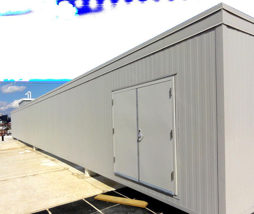


1 Maximum thermal performance ISOLEREN INSULATED METAL PANELS INSTALLATION GUIDE


2 Isoleren Installation Guide ALL INFORMATION CONTAINED IN THIS DOCUMENT IS SUBJECT TO CHANGE WITHOUT NOTICE
3 Table of Contents 2 Isoleren Profiles 3 Introduction Accountability Conditions Heavy Equipment 4 Verifying the Structure/Alignment Panel Side Joints Vapor Barrier, Sealants 5 Field Applied Insulation Threaded Fasteners Strippable Film 6 Field Cutting Appearance General Installation Sequence 13 Details 1
4 PROFILES Isoleren Profiles Infinity Isoleren ML Stucco Isoleren SL Impression Isoleren VL MesaLine Isoleren IM VeeLine WaveLine ShadowLine INTRODUCTION Introduction Insulated metal panels (IMPs) are premier building products on the leading edge of innovation. The panels are formed by a continuously, foamed-in-place manufacturing process which binds interior and exterior steel facings to a polyisocyanurate, insulating core. With exceptional R-values (R-8/inch), superior spanning capability, accelerated installation times, cost-effective pricing, recycled content, plus a rigid feel and streamlined architectural appearance the applications are limitless. The in-place performance of the aforementioned panels is critically dependent upon a quality installation hence the creation of the following manual. This installation guide is intended for use in conjunction with the construction drawings. If there is a conflict between this guide and the construction drawings, the construction drawings shall take precedent. ACCOUNTABILITY Accountability As with all construction projects, the contractor is ultimately responsible for the correct installation of the insulated metal panels. A high degree of logic and good judgment is expected and the contractor should be experienced. Most projects have their share of adjustments and changes and the contractor is responsible for addressing field issues. If a particular detail is not expressly addressed in this manual, the contractor should apply the principles illustrated herein to address the situation. An omission of this manual in no way absolves the installer of his responsibility for a quality, functioning install. If the contractor is presented with an insurmountable issue, he should immediately contact the manufacturer for assistance. CONDITIONS Conditions The information in this guide is based on the application of standard wall panels on typical building conditions. Required deviations are the responsibility of the installer. ATAS International, Inc. does not guarantee and cannot be held liable for the quality of installation. ATAS International, Inc. is not responsible for defects attributed to improper installation or the negligence of other parties. ATAS International, Inc. make no expressed or implied warranties pertaining to the fitness of the insulated wall panels or its components and shall not be responsible for any indirect or consequential damages, such as to building contents, nor for any further loss of any kind to the owner or contractor. ATAS International, Inc. does not warrant any product or material as meeting the ordinance, laws or regulations of any particular stated or local municipality, and ATAS International, Inc. is not responsible for conformance to such ordinances, law or regulations. ATAS International, Inc. is not liable for damage or loss of materials at the jobsite. 2
5 Heavy HEAVY Equipment EQUIPMENT Unloading the panel bundles will require a suitable fork lift or crane. Please refer to the Handling & Maintenance Guide for additional information. Verifying VERIFYING the THE Structure/Alignment STRUCTURE/ALIGNMENT Before panel installation begins, the wall structural support framing must be checked for straightness and alignment, and must be checked to verify that the wall panels can be installed without interference. Intermediate framing member s alignment tolerances are as specified below: zero to 1 4 outward of the structural support line for members spaced at 10-0 or greater zero to 1 8 outward of the structural support line for members spaced between 5-0 and 10-0 zero to 1 16 outward of the structural support line for members spaced at less than 5-0 Wall framing alignment error and interference must be corrected prior to the start of panel installation. The manufacturer is not responsible for difficult panel joint assembly and panel face rippling or buckling resulting from misaligned wall framing. Panel PANEL Side SIDE JOINTS Joints Panel side joints are a modified tongue and groove assembly. Every panel joint must be fully engaged. Due to normal fabrication and field tolerances, the actual panel coverage may vary between plus 1 8 to minus 1 16 when panel joints are fully engaged. The joint gap is the visible vertical space between the edges of the exterior faces on the adjacent panels. When panels are fully engaged, the width of the joint gap is typically plus 1 16 to plus 1. 8 Vapor VAPOR BARRIER Barrier If installed correctly, the combination of sealants and insulated panels forms the buildings vapor barrier. Because of increased thermal efficiency of insulated panel walls over other typical cladding products, there is a potentially greater vapor pressure differential between the exterior and the interior side of the wall. This higher vapor drive requires tremendous attention to detail regarding the application of sealants. Because of the critical requirements of the weather and vapor seals, the installer should understand the principles of vapor drive and water migration and must understand the requirements for the effective moisture and vapor control. It is the installer s responsibility to ensure that the specified sealants are in good condition and applied in the proper manner. It is the designer s responsibility to understand the project s unique environmental and operating conditions and to specify the appropriate vapor control measures. Location of vapor barrier sealants must be addressed by a design professional. Sealants SEALANTS Before wall panels are installed, ensure that all applicable interior trim is sealed and installed per the project drawings. A continuous perimeter sealant barrier is required between the panels and the structure/interior trim. In addition to the perimeter sealant, each panel side-joint must be sealed. These sealants, unless specified otherwise, are non-skinning butyls. All sealant beads must marry to provide 3
6 continuity. Joint sealant can be field or factory applied. Factory applied sealant must be inspected to ensure it is in place and continuous. If factory applied sealants are observed inadequate, the installer must field apply sealant to any areas of discontinuity. Field placed sealant must be applied continuously into the bottom of the groove(s). The bead size should be approximately 3 16 to 1 4. However, adjust the bead size to provide full contact with the tongue(s) of the next panel without extruding sealant onto the panel face. As stated previously, it is critical to ensure continuity of the sealant line at intersections between panel side joints and exterior and interior perimeter flashing assemblies. As each panel is installed, apply sealant pigtails along the panel s cross-section to provide a continuous seal between the side joint and the perimeter sealant. Sealant pigtails are defined as additional beads of sealant which are applied to the panel edge to serve as a bridge between the joint sealant and the perimeter flashing sealant. Pigtails are also used as a bridge between the perimeter flashing sealants and the flashing splice sealants. During panel installation, always check that the joint sealant and pigtail sealants are properly applied before engaging the panel joint. FIELD Field Applied APPLIED Insulation INSULATION To maintain the building s thermal efficiency and continuous insulation barrier, filler insulation is utilized to fill cavities that may occur at the wall corners, wall-to-roof transitions and wall transitions to other construction. Failure to fill the cavities with insulation can result in reduced thermal efficiency as well as moisture and ice damage within the wall construction and frost and condensation problems in the building interior. The filler insulation must be installed in a manner that maintains thermal efficiency across cavities where expansion/contraction is expected. Fiberglass filler insulation is typically used on commercial industrial work whereas field applied foam is typically utilized in cold-storage applications. The selection and procurement of filler insulation is the responsibility of the designer and installer. THREADED Threaded Fasteners FASTENERS The connection of the panels to the wall framing members is critical to the wall s load resistance performance and equally important to the wall s weathertight performance. It is the installer s responsibility to ensure that the specified fasteners are used and are installed in the proper manner and at the specified spacing. Reference the project s installation drawings for the specified fasteners and spacing. For typical applications the panels are attached to the framing members with clips and screws concealed within the panel joint. In some cases the design loads will require backside attachment of the panels to the framing members in addition to the clips. At wall corners, framed openings and wall termination, the edges of the panels are attached to the framing member with thru-panel screws. Do not overdrive fasteners. Overdriving can cause the fastener threads to strip, sealing washer damage and dimpling of the panel or flashing surface. The panel clip attachment screws must be driven until the panel face is secure against the framing member, but must not be overdriven to cause excessive crushing of the foam core and distortion of the metal panel edge. Distorting the panel edge will cause difficult panel joint assembly and may cause visible rippling of the panel s exterior face and excessive joint gaps. 4
7 Strippable STRIPPABLE Film FILM Remove any and all strippable films either prior to or directly following installation. Take measures to avoid exposure of the film to direct sunlight for more than 24 hours. Field FIELD Cutting CUTTING The panels are easily cut with circular saws using proper metal cutting blades. If the saw cannot cut through the entire panel thickness, or if shears or nibblers are used, cut each panel face and use a knife or handsaw to cut through the remaining foam core. Be sure to properly support the panel during the cutting operation to prevent delamination of the face from the core or buckling of the panel. When necessary, pad the saw s shoe plate and guides so they do not scuff or scratch the panel surfaces. Abrasive saws are not acceptable for cutting panels or flashing. Flashing is cut with quality shears to provide a precise, undamaged cut. Appearance APPEARANCE Always cushion the panel surfaces from direct contact with temporary supports of lifting slings and clamps, etc. To prevent bending or crushing damage, ensure that the panels are uniformly supported at adequate spacing. Do not handle the panels in a manner that can cause buckling of the faces, or separation of the faces from the core. Insulated panels have wide, virtually flat surfaces. Wide, flat metal surfaces are subject to uncontrollable oil canning. Many factors are causes for oil canning and no manufacturer can realistically assure the total elimination of the phenomenon. Therefore, uncontrollable oil canning is not a cause for rejection. However rippling and wrinkling caused by improper handling, overdriving clip fasteners or misalignment and deflection of the wall framing members can result in objectionable appearance and must be avoided. 5
8 General Installation Sequence General GENERAL Installation INSTALLATION Sequence SEQUENCE 1. Install and caulk the appropriate flashing/trims. 2. Measure and cut the first panel. 3. Place and plumb the first panel. 4. Through-fasten the cut edge. 5. Install clips and fasteners along the factory edge of the panel at the girt locations. 6. Apply sealant pigtails. 7. Field-caulk the second panel. 8. Place and engage the second panel. 9. Install clips and fasteners along the factory edge of the panel at the girt locations. 10. Continue. 6
9 7
10 8
11 9
12 10
13 11
14 12
15 Details Details DETAILS The following section of this manual contains details which address the installation of insulated metal wall panels and their associated flashings. The details are generic, showing typical wall framing and flashing conditions. Because of the many variations of applications and construction conditions, these generic details may vary from the project s actual conditions. Always reference the project s installation drawings for the specified requirements. If there are differences between the installation drawings and these installation guide details, the installation drawings will govern. 1. Panel Side-Lap (Joint) 2. Base 3. Outside Corner 4. Inside Corner 5. Door Header (Supported) 6. Door Header 7. Door Jamb 8. Window Header 9. Window Jamb 10. Window Sill 11. Side Joint 12. Stack Joint 13
16 14
17 15
18 16
19 17
20 18
21 19
22 20
23 21
24 22
25 23
26 24
27 25

28 ATAS ATAS International, International, Inc. Inc. Allentown, PA Mesa, AZ Maryville, TN ATAS International, Inc. Contact ATAS for more information. ATAS reserves the right to modify, eliminate and/or change its products without prior notification. LRD0417
Fundamentals of Insulated Panel Installation. MBCEA 2016 Clearwater, FL
 Fundamentals of Insulated Panel Installation MBCEA 2016 Clearwater, FL Fundamentals of Insulated Panel Installation Industrial Roof & Walls Not Architectural Not Cold Storage Topics Preparation Installation
ENVOLUTION INSULATED METAL WALL PANEL INSTALLATION GUIDE
 ENVOLUTION INSULATED METAL WALL PANEL INSTALLATION GUIDE CONTENTS INTRODUCTION...2 RESPONSIBILITIES 1. Customer s Responsibility...3 2. Disclaimers...3 INSTALLATION 1. Safe Installation...4 2. Installation
SECTION INSULATED METAL WALL PANELS. ATAS International, Inc. General Specification for Commercial/Industrial and Architectural Applications
 SECTION 07 42 13 INSULATED METAL WALL PANELS ATAS International, Inc. General Specification for Commercial/Industrial and Architectural Applications PART 1 GENERAL 1.1. Summary The contract drawings indicate
GENERAL SPECIFICATION FOR FIRE RATED APPLICATIONS
 I N SULROCK FIRE RATED METAL PANELS GENERAL SPECIFICATION FOR FIRE RATED APPLICATIONS 1. GENERAL 1.1. Summary Fire-rated panels as shown on the drawings shall be INSULROCK brand panels as supplied by Green
INSULATED METAL WALL PANEL HORIZONTAL APPLICATION TECHNICAL BULLETIN PIONEERING INSULATED METAL PANEL TECHNOLOGY
 INSULATED METAL WALL PANEL HORIZONTAL APPLICATION TECHNICAL BULLETIN PIONEERING INSULATED METAL PANEL TECHNOLOGY PIONEERING INSULATED METAL PANEL TECHNOLOGY INTRODUCTION The proven thermal and structural
SECTION STAINLESS STEEL WALL PANELS
 SECTION 07400 PART 1 GENERAL 1.1 SUMMARY A. Section Includes: 1. Dry joint, Rainscreen stainless steel wall panel system. 2. Accessories including attachments, clips, sub girts, shims, and fasteners 3.
SECTION INSULATED METAL ROOF PANELS. ATAS International, Inc. General Specification for Commercial/Industrial and Architectural Applications
 SECTION 07 41 13 INSULATED METAL ROOF PANELS ATAS International, Inc. General Specification for Commercial/Industrial and Architectural Applications PART 1 GENERAL 1.1. Summary The contract drawings indicate
Thermalsafe Fire Resistant Insulated Panel INSTALLATION GUIDE
 Thermalsafe Fire Resistant Insulated Panel INSTALLATION GUIDE CONTENTS INTRODUCTION...................................... 2 RESPONSIBILITIES 1. Customer s Responsibility.......................3 2. Disclaimers..................................3
Flushglaze For Steel Tube Applications and Horizontal Panels. Façades Installation Guide
 Flushglaze 7500 For Steel Tube pplications and Horizontal Panels Façades Installation Guide September 2016 BENCHMRK Welcome to Kingspan, global leaders in the design and manufacture of insulated metal
Duracast Pressure Plate Installation Instructions
 July 2015 EFCO CORPORATION 7/2015 PART NO. YW45 1 TABLE OF CONTENTS SECTION S-5600 / S-5900 DURACAST PRESSURE PLATE PAGE I. General Notes and Guidelines. 3-4 II. Glazing Preparation & Installation... 5
INSTALLATION THERMALSAFE FIRE RESISTANT INSULATED PANEL
 INSTALLATION GuIde THERMALSAFE FIRE RESISTANT INSULATED PANEL CONTENTS INTRODUCTION...................................... 2 RESPONSIBILITIES 1. Customer s Responsibility.......................3 2. Disclaimers..................................3
THERMALSAFE FIRE RESISTANT INSULATED PANEL INSTALLATION GUIDE PIONEERING INSULATED METAL PANEL TECHNOLOGY
 THERMALSAFE FIRE RESISTANT INSULATED PANEL INSTALLATION GUIDE PIONEERING INSULATED METAL PANEL TECHNOLOGY PIONEERING INSULATED METAL PANEL TECHNOLOGY CONTENTS INTRODUCTION......................................
INSTALLATION MANUAL. METAL INSULATED PANELS -ROXUL -Expanded Polystyrene
 INSTALLATION MANUAL METAL INSULATED PANELS -ROXUL -Expanded Polystyrene Insulated Metal Panels London Eco-Metal Manufacturing Inc. **Also see Eco-Metal s Handling Manual** These instructions are provided
Architectural Roof and Wall Products Guide Specifications
 Architectural Roof and Wall Products Guide Specifications Western States Metal Roofing 901 W. Watkins St. Phoenix, AZ 85007 PH: 602-495-0048 FX: 602-261-7726 FORMED METAL WALL PANELS This Guide Specification
[Project Name] Section [ ]
![[Project Name] Section [ ]](/thumbs/92/109284618.jpg "[Project Name] Section [ ]") Page 1 PART 1 - GENERAL 1.1 SECTION INCLUDES 1.1.1 Design, labor, products, equipment and services necessary for interior/exterior Aluminum Facade System (AFS) work, in accordance with the Contract Documents.
Page 1 PART 1 - GENERAL 1.1 SECTION INCLUDES 1.1.1 Design, labor, products, equipment and services necessary for interior/exterior Aluminum Facade System (AFS) work, in accordance with the Contract Documents.
SECTION COMPOSITE WALL PANELS PART 1 GENERAL 1.01 SECTION INCLUDES
 SECTION 07 4243 - PART 1 GENERAL 1.01 SECTION INCLUDES A. Composite wall panel system consisting of aluminum-faced composite panels in a rainscreen application as part of the assembly described below.
Architectural Roof and Wall Products Guide Specifications
 Architectural Roof and Wall Products Guide Specifications 901 W. Watkins St. Phoenix, AZ 85007 PH: 602-495-0048 FX: 602-261-7726 FORMED METAL ROOF AND WALL PANELS This Guide Specification is to be used
Architectural Wall Products Guide Specifications
 Western States Metal Roofing 901 W. Watkins St. Phoenix, AZ 85007 PH: 602-495-0048 FX: 602-261-7726 Architectural Wall Products Guide Specifications FORMED METAL WALL PANELS This Guide Specification is
Proper Installation of Insulated Metal Wall Panels
 Proper Installation of Insulated Metal Wall Panels Insulated metal panels (IMPs) are an ideal cladding solution for pre-engineered metal buildings. They are available in lengths up to 50, and may also
Installation Guidelines for all Quaker products with nail fins New construction nail fin installation with a drainable weather resistant barrier.
 www.quakerwindows.com www.quakercommercialwindows.com PO Box 128 504 Highway 63 South Freeburg, MO 65035 800-347-0438 573-469-4151 (fax) Installation Guidelines for all Quaker products with nail fins New
Exterior System installation instructions
 Exterior System installation instructions 11/20/14 WPS ES-400 & 500 INSTALLATION INSTRUCTION. The WPS ES-400 & 500 systems Façade panels are designed for use as an external wall cladding in conjunction
Architectural Roof Products Guide Specifications
 Western States Metal Roofing 901 W. Watkins St. Phoenix, AZ 85007 PH: 602-495-0048 FX: 602-261-7726 Architectural Roof Products Guide Specifications FORMED METAL ROOF AND WALL PANELS This Guide Specification
SECTION COPPER WALL PANELS. ***This section has been updated to IBC. Verify for specific project conditions.***
 ***This section has been updated to IBC. Verify for specific project conditions.*** PART 1 GENERAL 1.1 SUMMARY ***Edit to project requirements*** A. Section Includes: 1. Clear copper and preweathered copper
TABLE OF CONTENTS. 1.0 INTRODUCTION 1.1 Greenstone Structural Engineered Panels 1.2 Drawing and Element Numbers
 version 2.5 updated as of 08.04.2017 2 TABLE OF CONTENTS 1.0 INTRODUCTION 1.1 Greenstone Structural Engineered Panels 1.2 Drawing and Element Numbers 2.0 ASSEMBLY 2.1 Sequence of Assembly 2.2 Preparation
A M E R I C A N A R C H I T E C T U R A L M A N U F A C T U R E R S A S S O C I A T I O N
 A M E R I C A N A R C H I T E C T U R A L AAMA 2410-13 Standard Practice for Installation of Windows with an Exterior Flush Fin Over an Existing Window Frame M A N U F A C T U R E R S A S S O C I A T I
Architectural Roof Products Guide Specifications
 Western States Metal Roofing 901 W. Watkins St. Phoenix, AZ 85007 PH: 602-495-0048 FX: 602-261-7726 Architectural Roof Products Guide Specifications FORMED METAL ROOF AND WALL PANELS This Guide Specification
SECTION ALUMINUM-FRAMED ENTRANCES AND STOREFRONTS
 SECTION 08 4113 ALUMINUM-FRAMED ENTRANCES AND STOREFRONTS PART 1 GENERAL 1.1 SUMMARY A. Section Includes: 1. Aluminum entrance doors and frames. 2. Glass infill panels. 3. Door hardware. B. Related Sections:
METL-VISION WINDOW SYSTEM FOR HORIZONTAL WALL
 METL-VISION WINDOW SYSTEM FOR HORIZONTAL WALL TEchnical bulletin PIONEERING INSULATED METAL PANEL TECHNOLOGY PIONEERING INSULATED METAL PANEL TECHNOLOGY CONTENTS DETAIL TITLE FILE NO. PAGE NO. INTRODUCTION.......................................................................
SECTION COMPOSITE METAL WALL PANEL SYSTEM (Accu-Trac Low Profile DS)
") SECTION 07412 COMPOSITE METAL WALL PANEL SYSTEM (Accu-Trac Low Profile DS) PART 1 GENERAL 1.1 RELATED DOCUMENTS A. Drawings and general provisions of the Contract, including General and Supplementary Conditions
SECTION 07412 COMPOSITE METAL WALL PANEL SYSTEM (Accu-Trac Low Profile DS) PART 1 GENERAL 1.1 RELATED DOCUMENTS A. Drawings and general provisions of the Contract, including General and Supplementary Conditions
Specifiers: Click on the icon in the WORD toolbar to reveal detailed instructions
 Specifiers: Click on the icon in the WORD toolbar to reveal detailed instructions (Specifier Note: The purpose of this guide specification is to assist the specifier in correctly specifying perforated
All Metals Fabrication AMF FUSION DRILLFREE ALUMINUM COMPOSITE METAL (ACM) WALL PANEL SPECIFICATION
 WALL PANEL SPECIFICATION") SECTION 07 42 43 All Metals Fabrication AMF FUSION DRILLFREE ALUMINUM COMPOSITE METAL (ACM) WALL PANEL SPECIFICATION SPEC NOTE: Optional text is indicated by square brackets []. Delete unwanted items and
SECTION 07 42 43 All Metals Fabrication AMF FUSION DRILLFREE ALUMINUM COMPOSITE METAL (ACM) WALL PANEL SPECIFICATION SPEC NOTE: Optional text is indicated by square brackets []. Delete unwanted items and
DIVISION: THERMAL AND MOISTURE PROTECTION SECTION: METAL WALL PANELS REPORT HOLDER: METL SPAN, A DIVISION OF NCI GROUP, INC.
 0 Most Widely Accepted and Trusted ICC ES Evaluation Report ICC ES 000 (800) 423 6587 (562) 699 0543 www.icc es.org ESR 2218 Reissued 09/2017 This report is subject to renewal 09/2018. DIVISION: 07 00
SECTION PREFORMED CLADDING. A. Part A and DIVISION 1 of PART B are hereby made a part of this SECTION.
 SECTION 074213 PART 1 GENERAL 1.01 GENERAL REQUIREMENTS A. Part A and DIVISION 1 of PART B are hereby made a part of this SECTION. B. Examine all conditions as they exist at the project prior to submitting
Guardian Wall Panel Installation Manual
 Guardian 275 4 Wall Panel Installation Manual Guardian 275 4 Wall Panel Installation Manual This instructional manual provides General Installation Instruction. Installers should refer to the "as-built"
Page 1 of 5
 SPECIFICATIONS COMPOSITE MATERIAL PANEL SYSTEM ESTOLGA 1000 DRY SEAL SYSTEM PART 1 GENERAL 1.01 SECTION INCLUDES A. Exterior cladding consisting of formed metal composite material (MCM) sheet, secondary
SECTION EXTERIOR GRILLS AND SCREENS
 SECTION 10 82 13 PART 1 GENERAL PART 1 1 SUMMARY A. Section Includes: 1. Exterior perforated aluminum screen wall system with Ombrae TM Optical Tile imaging technology. 2. Accessories including attachments,
Code Compliance Research Report CCRR-0228
 Code Compliance Research Report CCRR-0228 Issue Date: 05-09-2017 Renewal Date: 05-11-2018 Revision Date: 06-23-2017 DIVISION: 07 00 00 THERMAL AND MOISTURE PROTECTION Section: 07 40 00 Roofing and Siding
12 - V0 CFP-12 PANEL INDEX. Delta Series CONCEALED FASTENED PANELS BUILDING PRODUCTS VERTICAL PANELS
 CONCEALED FASTENED PANELS CFP-12 PANEL INDEX 12 - V0 BASE DETAILS HORIZONTAL JOINT DETAIL PARAPET ROOF DETAIL INSIDE CORNER DETAIL OUTSIDE CORNER DETAIL SOFFIT DETAIL WINDOW JAMB DETAIL WINDOW HEAD DETAIL
Architectural Roof and Wall Products Guide Specifications
 Architectural Roof and Wall Products Guide Specifications 901 W. Watkins St. Phoenix, AZ 85007 PH: 602-495-0048 FX: 602-261-7726 FORMED METAL ROOF AND WALL PANELS This Guide Specification is to be used
SECTION EXTERIOR SOLID PHENOLIC RAINSCREEN PANELS
 SECTION 074233 EXTERIOR SOLID PHENOLIC RAINSCREEN PANELS PART 1 - GENERAL 1 RELATED DOCUMENTS A. Drawings and general provisions of the Contract, including General and Supplementary Conditions and Division
FACE CFP - HORIZONTAL PANELS - OPTION 'B'
 - Vertical Transitions 12F - H10.3 VHB TAPE 5.000" 127.0mm 5" FORMED TRANSITION STRIP w/ FLAT FACE CFP - - OPTION 'B' H10.3 CONCEALED FASTENED Panel Index 12F - H0 BASE DETAILS JOINT DETAIL PARAPET ROOF
NRM-7000 Guide Specifications
 NRM-7000 Guide Specifications MANUFACTURER www.nuraymetals.com sales@nuraymetals.com 800-700-7228 SECTION 07 411 PREFORMED ROOF & WALL PANELS PART 1 - GENERAL 1.1 SUMMARY A. Section includes complete system
 SPECIFICATIONS FOR AluSystems Aluminum Composite Panels Series 20 Dry Joint 1.00 GENERAL 1.01 RANGE OF WORK Section includes: Laminated panels and attachment systems for use as exterior cladding. A. Provide
C. All anchors, brackets, and hardware attachments necessary to complete the specified structural assembly, when included within project scope.
 SECTION 08 4519 - POLYCARBONATE WALL SYSTEM PART 1 GENERAL 1.1 SECTION INCLUDES A. Exterior System: The design, manufacture and installation of an aluminum and polycarbonate insulating translucent system.
A. Pre-Installation Conference: Conduct conference at [project site] <insert location>.
![A. Pre-Installation Conference: Conduct conference at [project site] <insert location>.](/thumbs/89/98511805.jpg "A. Pre-Installation Conference: Conduct conference at [project site] <insert location>.") SECTION 074213.23 METAL COMPOSITE MATERIAL WALL PANELS PART 1 GENERAL 1.1 SUMMARY A. Exterior cladding consisting of formed metal composite material (MCM) sheet, secondary supports and anchors to structure,
SECTION 074213.23 METAL COMPOSITE MATERIAL WALL PANELS PART 1 GENERAL 1.1 SUMMARY A. Exterior cladding consisting of formed metal composite material (MCM) sheet, secondary supports and anchors to structure,
KS SERIES - VERTICAL INSTALLATION
 CS-DS-01-KSV CS DISCLAIMER CS-PP-01-KSV PANEL PROFILES CS-PP-02-KSV PANEL PROFILES CS-PP-03-KSV PANEL PROFILES CS-PJ-01-KSV KS SERIES EXPANDED PANEL JOINT CS-PJ-02-KSV KS SERIES ENGAGED PANEL JOINT CS-PJ-03-KSV
A. Pre-Installation Conference: Conduct conference at [project site] <insert location>.
![A. Pre-Installation Conference: Conduct conference at [project site] <insert location>.](/thumbs/89/98511804.jpg "A. Pre-Installation Conference: Conduct conference at [project site] <insert location>.") SECTION 074213.23 METAL COMPOSITE MATERIAL WALL PANELS PART 1 GENERAL 1.1 SUMMARY A. Exterior cladding consisting of formed metal composite material (MCM) sheet, secondary supports and anchors to structure,
SECTION 074213.23 METAL COMPOSITE MATERIAL WALL PANELS PART 1 GENERAL 1.1 SUMMARY A. Exterior cladding consisting of formed metal composite material (MCM) sheet, secondary supports and anchors to structure,
Product Guide Specification
 Umicore Building Products USA, Inc. 3600 Glenwood Ave., Suite 250 Raleigh, North Carolina 27612 Phone (919) 874-7173 Fax (919) 874-7140 Website www.vmzinc-us.com E-mail info@vmzinc-us.com Product Guide
KARRIER PANEL - BRICK
 KPH-DS-01-BRICK KPH-PJ-01-BRICK KPH-PJ-02-BRICK KPH-PJ-03-BRICK KPH-BS-01-BRICK KPH-BS-02-BRICK KPH-BS-03-BRICK KPH-OC-01-BRICK KPH-FO-01-BRICK KPH-FO-02-BRICK KPH-FO-03-BRICK KPH-FO-04-BRICK KPH-FO-05-BRICK
ThermalSafe Insulated Metal Panels. Technical/Installation Information
 Insulated Metal Panels Technical/Installation Information IMPORTANT NOTICE READ THIS MANUAL COMPLETELY PRIOR TO BEGINNING THE INSTALLATION OF THE INSULATED METAL PANEL SYSTEM. MBCI MUST BE FOLLOWED AS
ELEVATION FOR DETAIL REFERENCE ONLY
 6 7 8 10 OUTSIDE CORNER 19 20 4 5 11 21 22 15 16 13 12 OPENING 14 SOFFIT 18 END WALL 17 INSIDE CORNER 9 6 7 8 ELEVATION FOR DETAIL REFERENCE ONLY CCV-01 CCV-02 CCV-03 CCV-04 CCV-05 CCV-06 CCV-07 CCV-08
FACADES - ACM BASE AT OVERHANG (WITH BASE FLASHING) INDEX SHEET
 INDEX SHEET") KPH-DS-01-MTLV KPH-PJ-01-MTLV KPH-PJ-02-MTLV KPH-PJ-03-MTLV KPH-PJ-04-MTLV KPH-PJ-05-MTLV KPH-BS-01-MTLV KPH-BS-02-MTLV KPH-BS-03-MTLV KPH-BS-04-MTLV KPH-OC-01-MTLV KPH-IC-01-MTLV KPH-SF-01-MTLV KPH-SF-02-MTLV
KPH-DS-01-MTLV KPH-PJ-01-MTLV KPH-PJ-02-MTLV KPH-PJ-03-MTLV KPH-PJ-04-MTLV KPH-PJ-05-MTLV KPH-BS-01-MTLV KPH-BS-02-MTLV KPH-BS-03-MTLV KPH-BS-04-MTLV KPH-OC-01-MTLV KPH-IC-01-MTLV KPH-SF-01-MTLV KPH-SF-02-MTLV
CONTOUR CORRUGATED PANEL
 CONTOUR CORRUGATED PANEL Table of Contents SECTION PAGE Designer Notes............................................... 1 Panel Net Coverage / Fasteners.................................... 2 ROOF Details
Installation Guide. PAROC panel solutions
 Installation Guide PAROC panel solutions Panel System 4.00 INT January 2008 THESE INSTRUCTIONS ARE FOR NORMAL APPLICATIONS Work safety Preparation Wear protective gloves and clothing when handling the
Corium Brick Rainscreen System Specifications
 CORIUM BRICK RAINSCREEN SYSTEM PART 1 - GENERAL 1.1 SUMMARY A. Work Included: The Work of this Section shall include but not be limited to the following: 1. Corium brick plates 2. Galvanized and coated
ThermaSteel Corporation ASSEMBLY MANUAL
 ThermaSteel Corporation ASSEMBLY MANUAL TABLE OF CONTENTS 1- INTRODUCTION 1.1 THERMASTEEL TM WALL PANELS 1.2 Drawing and Element Numbers 2- ASSEMBLY 2.1 Sequence of Assembly 2.2 Preparation of Foundation
INSTRUCTIONS AND GUIDELINES
 INSTRUCTIONS AND GUIDELINES NOISEBLOCK TM MODULAR PANEL SYSTEMS ENCLOSURES & PRESSURIZED PLENUMS PLANNING HINTS & NOTES: 1. Review the Kinetics Noise Control submittal and installation drawings and bill
Guide Specification for the OSI QUAD Window and Door Flashing System
 Henkel Corporation 26235 First Avenue Westlake, OH 1-866-591-2178 www.ositough.com Guide Specification for the OSI QUAD Window and Door Flashing System Specifier Note: The purpose of this guide specification
Technical Data Sheet
 Technical Data Sheet ProGUARD Concrete Insulated Sheathing Specifications & Installation Table Of Contents Product Description... pg. 1 Basic Use... pg. 1 Exterior Finishes... pg. 1 Standard Sizes... pg.
Ice Rink Renovation & New Clubhouse
 SECTION 074243- METAL COMPOSITE MATERIAL WALL PANELS PART 1 - GENERAL 1.1 RELATED DOCUMENTS A. Drawings and general provisions of the Contract, including General and Supplementary Conditions and Division
Installation Guide. This installation guide is furnished as a supplement to the project specific panel installation drawings.
 Installation Guide This installation guide is furnished as a supplement to the project specific panel installation drawings. Note: Variations from the contents of this guide can occur because of project
Guidance document January 2015
 Guidance document January 2015 A GUIDE TO SITE INSTALLATION OF INSULATED ROOF PANELS This bulletin introduces the reader to key issues that need to be addressed for the installation of an insulated roof
Student Services & Classroom Addition
 SECTION 074243 - METAL COMPOSITE MATERIAL WALL PANELS PART 1 - GENERAL 1.1 RELATED DOCUMENTS A. Drawings and general provisions of the Contract, including General and Supplementary Conditions and Division
Insulation. First Revison October DC14 Drainage Mat INSTALLATION GUIDE FOR RESIDENTIAL & COMMERCIAL APPLICATIONS
 Insulation First Revison October 2016 DC14 Drainage Mat INSTALLATION GUIDE FOR RESIDENTIAL & COMMERCIAL APPLICATIONS 1. General Information This Guide describes the use of Kingspan GreenGuard DC14 Drainage
GA APPLICATION OF GYPSUM SHEATHING
 1. Scope 1.1 This specification describes the minimum requirements for, and the methods of handling, storage, and application of, gypsum sheathing for use as a substrate for exterior claddings. 1.1.1 Exterior
PROJECT TITLE PROJECT NO: CONTRACT TITLE GRANT NO: UNIVERSITY OF CALIFORNIA, DAVIS DAVIS, CALIFORNIA
 The following standard specification is intended to be edited according to the specifics of the project. Brackets [ ] and areas shaded in gray [e.g. format] indicate requirements that are optional depending
Series B450 Guide Specification
 Boyd Aluminum Manufacturing Company P.O. Box 1565 3248 E. Division Street Springfield, MO 65801-1565 800-737-2800 417-862-1232 fax boydaluminum.com STOREFRONT SERIES B450 Shear Block Air Infiltration:
GM-CM30078-RevA. Metalcraft Insulated Panel Systems I Specification Guide V1 NZ I June
 GM-CM30078-RevA Metalcraft Insulated Panel Systems I Specification Guide V1 NZ I June 2017 2 Metalcraft Insulated Panel Systems I Specification Guide V1 NZ I June 2017 INDEX 1. General 2 2. Documents 2
Siding and Soffit Installation Guidelines
 Siding and Soffit Installation Guidelines email web phone 07 46 16 Longboard Siding & Soffit INTRODUCTION INSTALLATION GUIDELINES NOTE: These instructions are prepared for persons experienced in the field
SECTION PRE-ENGINEERED COLD-FORMED METAL ROOF AND FLOOR TRUSSES
 SECTION 05440- PRE-ENGINEERED COLD-FORMED METAL ROOF AND FLOOR TRUSSES PART 1 GENERAL 1.01 SUMMARY A. Section includes pre-engineered, pre-fabricated cold formed steel framing elements. Work includes:
Product and System Specifications DuPont Flashing Systems
 DuPont Building Innovations March 2007 4417 Lancaster Pike Chestnut Run Plaza 721 Wilmington, DE 19805 1-800-448-9835 www.construction.tyvek.com Product and System Specifications DuPont Flashing Systems
DuPont Tyvek Wall Underlay Install Guide
 DuPont Tyvek Wall Underlay Install Guide (For Residential & Light Commercial Buildings) Acceptable Solution to NZBC E2/AS1 New Zealand As at 1/4/15 Version 2 Subject to change without notice DuPont Tyvek
Architectural Roof & Wall Products Guide Specifications MANUFACTURER KLOECKNER METALS KALAELOA BLVD, KAPOLEI, HI 96707,
 Architectural Roof & Wall Products Guide Specifications MANUFACTURER KLOECKNER METALS 91-104 KALAELOA BLVD, KAPOLEI, HI 96707, 808-682-3000 This Guide Specification is to be used to develop an office master
Container Installation Guide
 Container Insulation Container Installation Guide Panels and Inserts The InSoFast CX Container panel and the Inserts are designed to fit most shipping containers. Containers have three types of corrugations:
SECTION TRANSLUCENT PANEL SYSTEM
 SECTION 084523 PART 1 GENERAL 1.1 RELATED DOCUMENTS A. Drawings and general provisions of the Contract, including General and Supplementary Conditions and Division 1 Specification Sections, apply to this
INNOVATION. TECHNOLOGY. SOLUTIONS. INSULATED PANELS SEE THE DIFFERENCE in appearance, value, performance and installation.
 INNOVATION. TECHNOLOGY. SOLUTIONS. INSULATED PANELS SEE THE DIFFERENCE in appearance, value, performance and installation. 1 2 Leading the industry in technology, design flexibility, quality, and value
Union County Vocational - Technical Schools Scotch Plains, New Jersey
 SECTION 074213 - INSULATED METAL WALL PANELS PART 1 - GENERAL 1.1 RELATED DOCUMENTS A. Drawings and general provisions of the Contract, including General and Supplementary Conditions and Division 01 Specification
RESIDENTIAL LIGHT GAUGE APPLICATION GUIDE
 Our Name Says It All RESIDENTIAL LIGHT GAUGE APPLICATION GUIDE Lebanon, PA 888.339.0059 Bridgton, ME 800.677.2060 Howe, IN 866.562.3782 www.everlastroofing.com Residential Light Gauge Table of Contents
SECTION TERRA COTTA CLAY TILE RAINSCREEN SYSTEM
 SECTION 07400 TERRA COTTA CLAY TILE RAINSCREEN SYSTEM PART 1 GENERAL 1.01 WORK INCLUDED A. The terra cotta clay tile elements and aluminum support system shall be manufactured by NBK Keramik GmbH as represented
B. Engineering design and performance requirements for terracotta baguette & fin assemblies.
 SECTION 07 4229 TERRACOTTA BAGUETTE & FIN ELEMENTS PART 1 GENERAL 1.1 SECTION INCLUDES A. Drawings and general provisions of the Contract, including General and Supplementary Conditions and Division 01
Series Outside glazed curtain wall. Installation instructions
 Series 5900 Outside glazed curtain wall Installation instructions Part NO. Y350 July 2015 SECTION TABLE OF CONTENTS PAGE I. General Notes & Guidelines 3-4 II. Perimeter Application...... 5-6 III. Anchor
SECTION ALUMINUM COMPOSITE WALL PANELS. ***This section has been updated to IBC. Verify for specific project conditions.***
 ***This section has been updated to IBC. Verify for specific project conditions.*** PART 1 GENERAL 1.1 SUMMARY ***Edit to project requirements*** A. Section Includes: 1. Aluminum faced, thermoplastic core,
FOR FIELD USE PLEASE DISTRIBUTE TO THE ERECTION CREW
 Insulated Wall Panel ERECTION MANUAL COVER INSTRUCTIONS FOR INSTALLING THE NBS INSULATED WALL PANEL FOR FIELD USE PLEASE DISTRIBUTE TO THE ERECTION CREW WATERLOO, IN 305 Industrial Parkway Waterloo, IN
DIVISION: THERMAL AND MOISTURE PROTECTION SECTION: ROOFING AND SIDING PANELS REPORT HOLDER: KINGSPAN INSULATED PANELS, INC.
 0 Most Widely Accepted and Trusted ICC-ES Report ICC-ES 000 (800) 423-6587 (562) 699-0543 www.icc-es.org ESR-1143 Reissued 04/2017 This report is subject to renewal 04/2018. DIVISION: 07 00 00 THERMAL
B. Engineering design and performance requirements for terracotta rainscreen assemblies.
 SECTION 07 4229 TERRACOTTA CLAY TILE RAINSCREEN ASSEMBLY SPECIFICTION FOR TERRART LIGHT PART 1 GENERAL 1.1 SECTION INCLUDES A. Drawings and general provisions of the Contract, including General and Supplementary
C. Engineering design and performance requirements for terracotta rainscreen assemblies.
 SECTION 07 4229 TERRACOTTA CLAY TILE RAINSCREEN ASSEMBLY SPECIFICTION FOR TERRART LARGE PART 1 GENERAL 1.1 SECTION INCLUDES A. Drawings and general provisions of the Contract, including General and Supplementary
COLOR SELECTION. Cool
 INSULATED WALL PANELS INSULATED ROOF PANELS Each project follows a different set of parameters and, as such, may require a different set of wall panels. We offer a selection of panels to accommodate the
B. Engineering design and performance requirements for terracotta rainscreen assemblies.
 SECTION 07 4229 TERRACOTTA CLAY TILE RAINSCREEN ASSEMBLY SPECIFICTION FOR TERRART LARGE PART 1 GENERAL 1.1 SECTION INCLUDES A. Drawings and general provisions of the Contract, including General and Supplementary
Tender No Section St. James - Assiniboia Centennial Pool Fitness Facility Addition Page 1
 Fitness Facility Addition Page 1 PART 1 GENERAL 1.1 SECTION INCLUDES.1 Extruded aluminum windows with fixed sash..2 Factory glazed..3 Perimeter sealant. 1.2 RELATED SECTIONS.1 Section 05500 - Metal Fabrications.2
SECTION THERMOPLASTIC MEMBRANE ROOFING PART 1 GENERAL 1.01 SECTION INCLUDES
 SECTION 07540 - THERMOPLASTIC MEMBRANE ROOFING PART 1 GENERAL 1.01 SECTION INCLUDES A. Mechanically attached system with thermoplastic roofing membrane. B. Insulation, flat and tapered. C. Flashings. D.
COMMERCIAL & INDUSTRIAL CI-CFR-INDEX SHEET INDEX CI-CFR-INDEX SHEET INDEX CI-CFR-INFO C & I DISCLAIMER
 CI-CFR-INDEX SHEET INDEX CI-CFR-INFO C & I DISCLAIMER CI-CFR-LG LEGEND CI-CFR-JT-01 PANEL JOINT CI-CFR-JT-02 PANEL JOINT SEQUENCE CI-CFR-JT-03 PANEL JOINT LAYOUT CI-CFR-SQ-01 PANEL INSTALLATION SEQUENCE
Metafor Panel System Installation Guide
 Installation Guide innovative cladding design solutions Product Description Universal Flashing Kit Supplemental Guide for VM Pro-Zinc Training To enroll in a VM PRO-ZINC Training Course contact: UMICORE
EVERSEAM 20 APPLICATION GUIDE
 EVERSEAM 20 APPLICATION GUIDE Panel Overview Our Name Says It All!"#$%#&'()*+,!"#$%#&'(-.( Applications: The EverSeam panel is an architectural panel that is ideal for residential and light commercial
Technical Data Sheet
 Technical Data Sheet Perimeter Installation Procedures Concrete Faced Insulated Perimeter Wall Panels Concrete Faced Insulated Perimeter Wall Panels are prefinished, one-step exterior insulating panels
SERIES STB30 STEEL FIXED THERMAL BREAK DETENTION WINDOWS SECTION 08651
 SERIES STB30 STEEL FIXED THERMAL BREAK DETENTION WINDOWS SECTION 08651 PART 1 GENERAL 1.1 DESCRIPTION A. Work Included: 1. Furnish all labor and materials to complete the fabrication of detention windows
EQUITONE is a material supplier. Installation Contractors shall be trained and approved by EQUITONE.
 This specification has been numbered, organized and formatted in accordance with the MasterFormat, Section Format and Page Format documents published jointly by Construction Specifications Institute (CSI)
19 East Ave. Mullica Hill, N.J Phone: Fax: ARCHITECTURAL FOAM FABRICATORS, LLC.
 Table of Contents Trims...1-17 Sills...18-21 Frieze Boards...22-23 Cornices...24-28 Bands...29-32 Keystones...33-35 Pilasters...36 Columns...37-39 Quoins...40 Arches & Circles...41-42 4 1/2 Trims 7 6 14
SECTION METAL FRAMED SKYLIGHT. A. Engineering, preparation of fabrication drawings and structural calculations for the entire skylight system.
 SECTION 08625 METAL FRAMED SKYLIGHT PART 1 GENERAL 1.01 SECTION INCLUDES: A. Engineering, preparation of fabrication drawings and structural calculations for the entire skylight system. B. Fabrication
PART 1 / GENERAL SECTION ALUMINUM PLATE PANEL SYSTEM. ALPLY Insulated Panels. Alply TECH WALL Aluminum Plate System 2002
 SECTION 07 42 13 ALUMINUM PLATE PANEL SYSTEM ALPLY Insulated Panels Alply TECH WALL Aluminum Plate System 2002 PART 1 / GENERAL 1.1 SYSTEM DESCRIPTION A. Preformed Aluminum Plate System for Screen wall
SECTION PORCELAIN TILE WALL SYSTEM. (Porcelanosa Venis Urbatek)
") SECTION 074251 (Porcelanosa Venis Urbatek) PART 1 - GENERAL 1.1 GENERAL PROVISIONS A. Attention is directed to the CONTRACT AND GENERAL CONDITIONS and all Sections within DIVISION 01 - GENERAL REQUIREMENTS
SECTION 074251 (Porcelanosa Venis Urbatek) PART 1 - GENERAL 1.1 GENERAL PROVISIONS A. Attention is directed to the CONTRACT AND GENERAL CONDITIONS and all Sections within DIVISION 01 - GENERAL REQUIREMENTS